2004 forester service manual quick …fuji heavy industries ltd. g8080ge7 2004 forester service...
TRANSCRIPT

2004 FORESTER SERVICE MANUAL QUICK REFERENCE INDEX
BODY SECTION
This service manual has been preparedto provide SUBARU service personnelwith the necessary information and datafor the correct maintenance and repairof SUBARU vehicles.This manual includes the proceduresfor maintenance, disassembling, reas-sembling, inspection and adjustment ofcomponents and diagnostics for guid-ance of experienced mechanics.Please peruse and utilize this manualfully to ensure complete repair work forsatisfying our customers by keepingtheir vehicle in optimum condition.When replacement of parts duringrepair work is needed, be sure to useSUBARU genuine parts.
All information, illustration and specifi-cations contained in this manual arebased on the latest product informationavailable at the time of publicationapproval.
FUJI HEAVY INDUSTRIES LTD.
HVAC SYSTEM (HEATER, VENTILATOR AND A/C)
AC
HVAC SYSTEM (AUTO A/C)(DIAGNOSTIC)
AC
AIRBAG SYSTEM AB
AIRBAG SYSTEM (DIAGNOSTIC) AB
SEAT BELT SYSTEM SB
LIGHTING SYSTEM LI
WIPER AND WASHER SYSTEM WW
ENTERTAINMENT ET
COMMUNICATION SYSTEM COM
GLASS/WINDOW/MIRROR GW
BODY STRUCTURE BS
INSTRUMENTATION/DRIVER INFO IDI
SEAT SE
SECURITY AND LOCK SL
SUNROOF/T-TOP/CONVERTIBLE TOP (SUNROOF)
SR
EXTERIOR/INTERIOR TRIM EI
EXTERIOR BODY PANEL EB
G8080GE7

2004 FORESTER SERVICE MANUAL QUICK REFERENCE INDEX
BODY SECTION
CRUISE CONTROL SYSTEM CC
CRUISE CONTROL SYSTEM(DIAGNOSTIC)
CC(H4SO)
CRUISE CONTROL SYSTEM(DIAGNOSTIC)
CC(H4DOTC)
CRUISE CONTROL SYSTEM(DIAGNOSTIC)
CC(H4DOTC 2.5)
IMMOBILIZER (DIAGNOSTIC) IM
G8080GE7

EXTERIOR BODY PANEL
EB
Page1. General Description ....................................................................................22. Front Hood Panel ........................................................................................93. Front Fender Panel ...................................................................................104. Front Door Panel.......................................................................................115. Front Sealing Cover ..................................................................................136. Rear Door Panel .......................................................................................147. Rear Sealing Cover...................................................................................168. Rear Gate Panel .......................................................................................179. Rear Gate Garnish Assembly ...................................................................20

EXTERIOR BODY PANELGeneral Description
1. General DescriptionA: SPECIFICATION
(1) Front hood panel (4) Rear door panel (7) Side sill
(2) Front fender panel (5) Rear quarter panel
(3) Front door panel (6) Door panel
Section Part Specification
(A) Front hood panel to Front fender panel 3.5±1.0 mm (0.14±0.04 in)
(B) Front fender panel to Front door panel 4.7±1.0 mm (0.19±0.04 in)
(C) Front door panel to Rear door panel 5.0 mm (0.20 in)
(D) Rear door panel to Rear quarter panel 4.6 mm (0.18 in)
(E), (F) Door panel to Side sill 5.9 mm (0.23 in)
(A)
(A)
(C)
(D)
(5)
(4)
(3) (4)
(2) (3)
(B)
(6)
(7)
(E),(F)
(1)
(2)
(B) (C)
(E) (F)
(D)
EB-00001
EB-2

EXTERIOR BODY PANELGeneral Description
B: COMPONENT1. FRONT HOOD
(1) Front hood (3) Seal Tightening torque: N·m (kgf-m, ft-lb)
(2) Hinge T1: 24.5 (2.5, 18.1)
EB-00038
(3)
T1
T1
(2)
(1)
EB-3

EXTERIOR BODY PANELGeneral Description
2. FRONT FENDER PANEL
(1) Front fender panel Tightening torque: N·m (kgf-m, ft-lb)T: 7.4 (0.75, 5.5)
EB-00003
T
T
(1)
EB-4

EXTERIOR BODY PANELGeneral Description
3. FRONT DOOR PANEL
(1) Gusset (9) Upper hinge Tightening torque: N·m (kgf-m, ft-lb)(2) Weather strip (10) Key cylinder (Driver’s side only) T1: 7.5 (0.76, 5.5)(3) Stabilizer (Outer) (11) Front sash T2: 14 (1.4, 10.3)(4) Stabilizer (Inner) (12) Rear sash T3: 25 (2.5, 18)(5) Door panel (13) Guide rail T4: 30 (3.1, 22)(6) Checker T5: 33 (3.4, 24)(7) Sealing cover T6: 6 (0.6, 4.4)(8) Lower hinge T7: 1.5 (0.15, 1.1)
EB-00183
T1
T6
T6
T3
T3
T4
T5
T4
(4)
(2)
(1)
(9)
(5)
(6)
(13)
(12)
(7)
(11)
(8)
(10)
T6
T6
T2T2
T2
T2
T1
(3)
T7
EB-5

EXTERIOR BODY PANELGeneral Description
4. REAR DOOR PANEL
(1) Weather strip (8) Rear sash Tightening torque: N·m (kgf-m, ft-lb)(2) Stabilizer (Outer) (9) Lower hinge T1: 7.5 (0.76, 5.5)(3) Stabilizer (Inner) (10) Upper hinge T2: 25 (2.5, 18)(4) Door panel T3: 30 (3.1, 18)(5) Checker T4: 33 (3.4, 24)(6) Sealing cover T5: 14 (1.4, 10.3)(7) Front sash T6: 1.5 (0.15, 1.1)
EB-00174
T1
T6
T1
(1)
(3)
(7)
T2
T2
T6
T5
T3
T4T3
(10)
(4)
(5)
(6)(9)
T5
(8)
(2)
T5T5
EB-6

EXTERIOR BODY PANELGeneral Description
5. REAR GATE PANEL
(1) Damper stay (3) Rear gate Tightening torque: N·m (kgf-m, ft-lb)(2) Hinge (4) Rear gate garnish T1: 7.5 (0.76, 5.5)
T2: 14 (1.4, 10.1)T3: 25 (2.5, 18.1)
EB-00037
T1
(2)
(3)
(4)
(1)
T2
T3
T1
T1
T1
EB-7

EXTERIOR BODY PANELGeneral Description
C: PREPARATION TOOL1. SPECIAL TOOL
2. GENERAL TOOL
ILLUSTRATION TOOL NUMBER DESCRIPTION REMARKS
925610000 WRENCH Used for removing and installing door hinge.
TOOL NAME REMARKS
Support jack Used for supporting door panel.
ST-925610000
EB-8

EXTERIOR BODY PANELFront Hood Panel
2. Front Hood PanelA: REMOVAL1) Open the front hood to remove washer nozzles.2) Release the clips to remove front hood insulator.
3) Remove the bolts to remove front hood from hinges.
B: INSTALLATION1) Install in the reverse order of removal.2) Adjust the clearance between front hood paneland front fender panel. Clearance must be equal atboth sides.
Tightening torque:24.5 N·m (2.5 kgf-m, 18.1 ft-lb)
C: ADJUSTMENT1) Use the hinge mounting holes to align the fronthood longitudinally and laterally.
2) Adjust the height at front end of hood. <Ref. toSL-33, ADJUSTMENT, Front Hood Lock Assem-bly.>
3) Rotate the hood buffer to adjust lateral height.
EB-00008
EB-00009
EB-00009
EB-00010
EB-9

EXTERIOR BODY PANELFront Fender Panel
3. Front Fender PanelA: REMOVAL1) Disconnect the ground cable from battery.2) Remove the front bumper face. <Ref. to EI-23,REMOVAL, Front Bumper.>3) Remove the mud guard. <Ref. to EI-31, RE-MOVAL, Mud Guard.>4) Remove the side sill spoiler. <Ref. to EI-33, RE-MOVAL, Side Sill Spoiler.>5) Remove the side protector. <Ref. to EI-34, RE-MOVAL, Side Garnish.>6) Loosen the bolts and clip to remove front fenderpanel.
B: INSTALLATION1) Install in the reverse order of removal.2) When the front fender panel is installed, clear-ance between front fender panel and front hoodpanel must be equal.
Tightening torque:7.4 N·m (0.75 kgf-m, 5.5 ft-lb)
EB-00011
EB-10

EXTERIOR BODY PANELFront Door Panel
4. Front Door PanelA: REMOVAL1) Disconnect the ground cable from battery.2) Remove the front door trim. <Ref. to EI-35, RE-MOVAL, Front Door Trim.>3) Remove the outer mirror assembly. <Ref. toGW-12, REMOVAL, Outer Mirror Assembly.>4) Remove the front sealing cover. <Ref. to EB-13,REMOVAL, Front Sealing Cover.>5) Remove the front door glass. <Ref. to GW-17,REMOVAL, Front Door Glass.>6) Remove the front door regulator and motor. <Ref.to GW-21, REMOVAL, Front Regulator and MotorAssembly.>7) Remove the front door latch assembly. <Ref. toSL-24, REMOVAL, Front Door Latch Assembly.>8) Remove the front outer handle. <Ref. to SL-23,REMOVAL, Front Outer Handle.>9) Remove the front pillar lower trim to disconnectthe connector from body harness.
10) Put a wooden block on jack and place jack underdoor. Support the door with a jack to protect it fromdamage.
NOTE:When supporting the door with a jack, be carefulnot to deform the door hinges while working.
11) Remove the checker bolts.
12) Remove the door-side bolts for upper and low-er hinges to remove the front door panel.
13) Using the ST, remove the body-side bolts forupper and lower hinges, and remove door hinges.ST 925610000 WRENCH
B: INSTALLATION1) Install in the reverse order of removal.2) Apply grease to the sliding area of door hinges.3) Refer to COMPONENT in General Description fortightening torque. <Ref. to EB-6, REAR DOOR PAN-EL, COMPONENT, General Description.>
EB-00012
EB-00013
EB-00014
EB-00015
EB-00016
ST
EB-11

EXTERIOR BODY PANELFront Door Panel
C: ADJUSTMENT1) Using the ST, loosen the body-side bolts of upperand lower hinges to align the position of front doorpanel longitudinally and vertically.ST 925610000 WRENCH
2) Loosen the door-side bolts of upper and lowerhinges to align the position of front door panel ver-tically and laterally at the front end.
3) Loosen the screw (A) and lightly tap striker (B)using a plastic hammer to adjust striker to align theposition of front door panel vertically and laterally atthe rear end.
CAUTION:Do not use an impact wrench. Welding area on the striker nut plate is easily broken.
EB-00016
ST
EB-00015
EB-00017
(B)(A)
EB-12

EXTERIOR BODY PANELFront Sealing Cover
5. Front Sealing CoverA: REMOVAL1) Disconnect the ground cable from battery.2) Remove the front door trim. <Ref. to EI-35,REMOVAL, Front Door Trim.>3) Remove the front speaker. <Ref. to ET-6, RE-MOVAL, Front Speaker.>4) Remove the door trim bracket.
5) Remove the sealing cover.
NOTE:• Carefully remove the butyl tape. Excessive forcewill easily break the cover.• If the cover gets broken, replace it with a newone.
B: INSTALLATION1) Install in the reverse order of removal.2) When replacing the sealing cover, use butyl tape.3) Press the butyl tape-applied area firmly to pre-vent any floating on surface.
Butyl tape: 3M8626 or equivalent
NOTE:• Apply a uniform bead of butyl tape.• Attach the sealing cover, keeping it from becom-ing wrinkled.• Breaks in the bead will allow water leakage andcontamination.
C: INSPECTIONIf the sealing cover is damaged, replace it with anew one.
EB-00034
EB-00018
EB-13

EXTERIOR BODY PANELRear Door Panel
6. Rear Door PanelA: REMOVAL1) Disconnect the ground cable from battery.2) Remove the rear door trim. <Ref. to EI-36, RE-MOVAL, Rear Door Trim.>3) Remove the rear sealing cover. <Ref. to EB-16,REMOVAL, Rear Sealing Cover.>4) Remove the rear door glass. <Ref. to GW-22,REMOVAL, Rear Door Glass.>5) Remove the rear door regulator and motor as-sembly. <Ref. to GW-24, REMOVAL, Rear Regula-tor and Motor Assembly.>6) Remove the rear door latch assembly. <Ref. toSL-28, REMOVAL, Rear Door Latch Assembly.>7) Remove the rear outer handle. <Ref. to SL-27,REMOVAL, Rear Outer Handle.>8) Remove the center pillar lower trim. <Ref. to EI-44, REMOVAL, Lower Inner Trim.>9) Remove the seat belt bracket and blind plug.Disconnect the connector of door harness and re-move the door hinge nut.
10) Put a wooden block on the jack and place thejack under the door. Support the door with the jackto protect it.
NOTE:When supporting the door with a jack, be carefulnot to deform the door hinges while working.
11) Remove the checker bolts.
12) Remove the door-side bolts for upper and low-er hinges to remove the rear door panel.
13) Using the ST, remove the body-side bolts forupper and lower hinges, and remove door hinges.ST 925610000 WRENCH
B: INSTALLATION1) Install in the reverse order of removal.2) Apply grease to the sliding area of door hinges.3) Refer to COMPONENT in General Description fortightening torque. <Ref. to EB-6, REAR DOORPANEL, COMPONENT, General Description.>
C: ADJUSTMENT1) Using the ST, loosen the body-side bolts of up-per and lower hinges to align the position of reardoor panel longitudinally and vertically.ST 925610000 WRENCH
EB-00019
EB-00013
EB-00014
EB-00015
EB-00016
ST
EB-14

EXTERIOR BODY PANELRear Door Panel
2) Loosen the door-side bolts of upper and lower hing-es to align the position of rear door panel vertically andlaterally at front-end.
3) Loosen the screw (A) and lightly tap striker (B) usingplastic hammer to adjust striker to align the position ofrear door panel vertically and laterally at the rear end.
CAUTION:Do not use an impact wrench. The welding area on the striker nut plate is easily broken.
EB-00015
EB-00017
(B)(A)
EB-15

EXTERIOR BODY PANELRear Sealing Cover
7. Rear Sealing CoverA: REMOVAL1) Disconnect the ground cable from battery.2) Remove the rear door trim. <Ref. to EI-36, RE-MOVAL, Rear Door Trim.>3) Remove the door trim bracket.
4) Remove the sealing cover.
NOTE:• Carefully remove the butyl tape. Excessive forcewill easily break the cover.• If the cover gets broken, replace it with a newone.
B: INSTALLATION1) Install in the reverse order of removal.2) When replacing the sealing cover, use butyl tape.3) Press the butyl tape-applied area firmly to pre-vent any floating on surface.
Butyl tape:3M8626 or equivalent
NOTE:• Apply an uniform bead of butyl tape.• Attach the sealing cover, keeping it from becom-ing wrinkled.• Breaks in the bead will allow water leakage andcontamination.
C: INSPECTIONIf the sealing cover is damaged, replace it with a newone.
EB-00034
EB-00018
EB-16

EXTERIOR BODY PANELRear Gate Panel
8. Rear Gate PanelA: REMOVAL1. REAR GATE PANEL1) Disconnect the ground cable from battery.2) Open the rear gate.3) Remove the rear gate trim. <Ref. to EI-48, RE-MOVAL, Rear Gate Trim.>4) Remove the rear wiper motor. <Ref. to WW-17,REMOVAL, Rear Wiper Motor.>5) Remove the rear gate garnish assembly. <Ref. toEB-20, REMOVAL, Rear Gate Garnish Assembly.>6) Remove the rear gate outer handle. <Ref. to SL-30, REMOVAL, Rear Gate Outer Handle.>7) Remove the rear gate latch assembly. <Ref. toSL-31, REMOVAL, Rear Gate Latch Assembly.>8) Disconnect the connectors of rear wiper, reardefogger, and other lighting devices.9) Disconnect the washer hose.10) Remove the rubber duct (A) connection, and pullout the harness and washer hose from rear gate.
11) Using a support, support the rear gate and thenremove damper stay mounting bolts.
NOTE:When the rear gate is released, it may hit and dam-age the body. To prevent this, place a shop cloth be-tween the body and gate.12) Loosen the rear gate bolts to remove rear gate.
(A)
EB-00020
EB-00021
EB-00022
EB-00023
EB-17

EXTERIOR BODY PANELRear Gate Panel
2. REAR GATE DAMPER STAY1) Open the rear gate. Use a support to support therear gate.
NOTE:After the rear gate damper stay is removed, the reargate cannot stay open. Supporting the rear gate witha jack, remove the bolts.
CAUTION:• Do not damage the piston rods and oil seals.• Never disassemble the cylinders: They con-tain gas.2) Loosen the bolts to remove the rear gate damperstay from rear gate.
B: INSTALLATION1. REAR GATE PANEL1) Install in the reverse order of removal.2) Install the rear gate panel with uniform clearanceto the body.3) Refer to COMPONENT of General Description fortightening torque. <Ref. to EB-7, REAR GATE PAN-EL, COMPONENT, General Description.>
NOTE:After supporting the rear gate with a jack, startworking.
2. REAR GATE DAMPER STAY1) Install the mounting bolt (A) to the rear gate pan-el and body.
Tightening torque:14 N·m (1.43 kgf-m, 10.3 ft-lb)
2) Firmly install the rear gate damper stay (B) tomounting bolt (A).
3) Tighten the bolts at upper side of rear gate damp-er stay.
Tightening torque:7.5 N·m (0.76 kgf-m, 5.5 ft-lb)
EB-00021
EB-00024
(A)(B)
EB-00075
EB-18
EXTERIOR BODY PANELRear Gate Panel
C: DISPOSAL1. REAR GATE DAMPER STAY
CAUTION:Gas is colorless, odorless and harmless. How-ever, gas pressure may spray cutting powder or oil. Be sure to wear dust-resistant goggles.1) Cover with a vinyl case as shown in the figure.
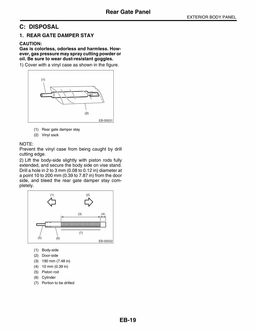
NOTE:Prevent the vinyl case from being caught by drillcutting edge.2) Lift the body-side slightly with piston rods fullyextended, and secure the body side on vise stand.Drill a hole in 2 to 3 mm (0.08 to 0.12 in) diameter ata point 10 to 200 mm (0.39 to 7.87 in) from the doorside, and bleed the rear gate damper stay com-pletely.
(1) Rear gate damper stay
(2) Vinyl sack
(1) Body-side
(2) Door-side
(3) 190 mm (7.48 in)
(4) 10 mm (0.39 in)
(5) Piston rod
(6) Cylinder
(7) Portion to be drilled
(1)
(2)
EB-00031
(3) (4)
(1)
(5) (6)
(7)
(2)
EB-00032
EB-19

EXTERIOR BODY PANELRear Gate Garnish Assembly
9. Rear Gate Garnish AssemblyA: REMOVAL1) Remove the rear gate panel trim. <Ref. to EI-48,REMOVAL, Rear Gate Trim.>2) Remove the rear wiper motor. <Ref. to WW-17,REMOVAL, Rear Wiper Motor.>3) Remove the seven frange nuts from inside ofrear gate panel. 4) Remove the license plate light assembly. 5) Close the gate, and then remove the rear gategarnish assembly, pulling it forward by hand.
NOTE:Be careful not to pull it strongly to avoid damage toclips.
B: INSTALLATIONInstall in the reverse order of removal.
C: INSPECTIONCheck for serious scratches or cracks in rear gategarnish assembly.
(1) Rear gate garnish ASSY
(2) Licence plate light bracket
(3) Licence plate light
EB-00033
(1)
(2)
(3)
EB-20