2.0 project description - california public utilities commission project... · 1 2.0 project...
TRANSCRIPT
SANTA BARBARA COUNTY RELIABILITY PROJECT
2.0 PROJECT DESCRIPTION
MAY 2015 2‐1 FINAL EIR
2.0 Project Description 12SouthernCaliforniaEdisonCompany(SCE,ortheapplicant)proposestoconstructtheSanta3BarbaraCountyReliabilityProject(proposedproject)betweentheCityofVentura,inVentura4County,andtheCityofCarpinteria,inSantaBarbaraCounty.Theproposedprojectcomprisesthe5following:67
Removaland/orreplacementofexisting66‐kilovolt(kV)subtransmissionstructures8facilities,primarilywithinexistingutilityrights‐of‐way(ROWs)betweentheexistingSanta9ClaraSubstationinVenturaCountyandtheexistingCarpinteriaSubstationinSantaBarbara10County.11
Installationofmarkerballsonoverheadwirewheredeterminednecessary.12
ModificationofsubtransmissionandsubstationequipmentwithintheexistingCarpinteria13Substation,CasitasSubstation,andSantaClaraSubstation.14
Replacementoflineprotectionrelayswithinexistingsubstationequipmentroomsor15cabinetsattheGettySubstation,GoletaSubstation,OrtegaSubstation,andSantaBarbara16Substation.17
Installationoftelecommunicationsfacilitiestoconnecttheproposedprojecttothe18applicant’sexistingtelecommunicationssystemfortheprotection,monitoring,andcontrol19ofsubtransmissionandsubstationequipment.20
Installationofnewtelecommunicationsfacilitiesalongreconstructedsubtransmission21segmentsandattheCarpinteriaSubstation,CasitasSubstation,SantaClaraSubstation,and22VenturaSubstation.23
Transferofdistributionlines(andthird‐partyinfrastructureasnecessary)tonew24subtransmissionstructures.25
Removalofsubtransmissioninfrastructure,suchastowerfoundationfootings,26decommissionedduringprevious66‐kVreconstructionactivitiesbetween1999and2004.27
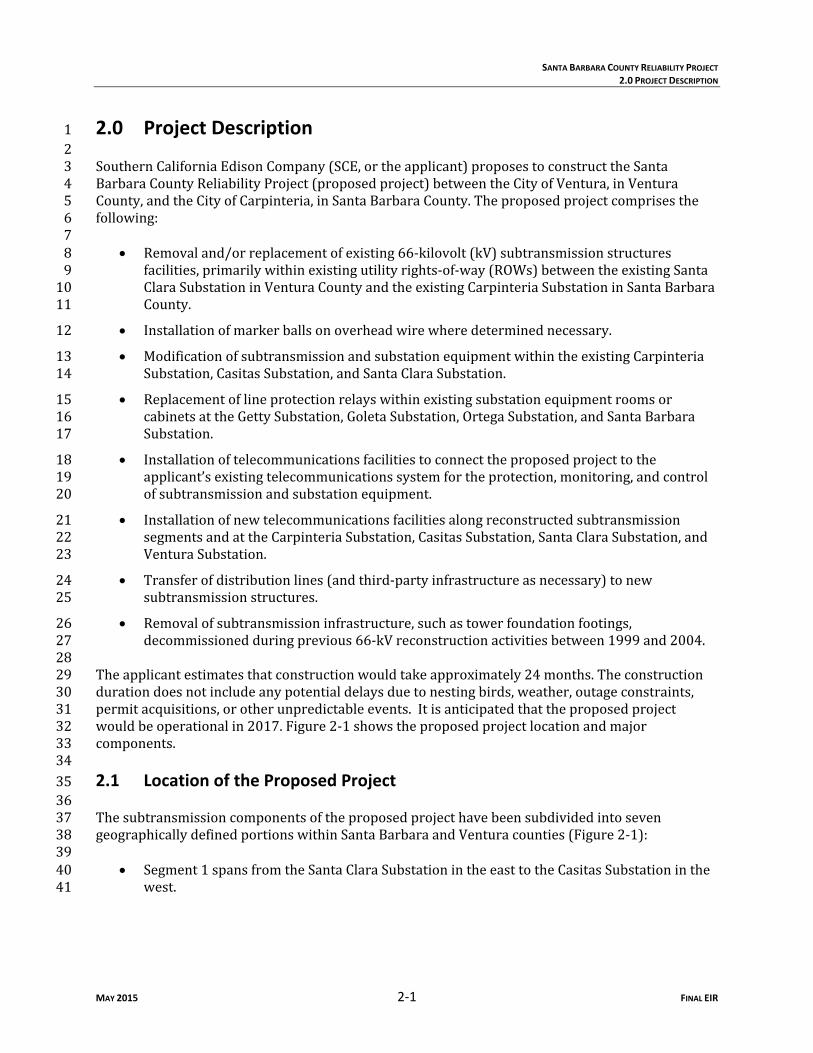
28Theapplicantestimatesthatconstructionwouldtakeapproximately24months.Theconstruction29durationdoesnotincludeanypotentialdelaysduetonestingbirds,weather,outageconstraints,30permitacquisitions,orotherunpredictableevents.Itisanticipatedthattheproposedproject31wouldbeoperationalin2017.Figure2‐1showstheproposedprojectlocationandmajor32components.33342.1 Location of the Proposed Project 3536Thesubtransmissioncomponentsoftheproposedprojecthavebeensubdividedintoseven37geographicallydefinedportionswithinSantaBarbaraandVenturacounties(Figure2‐1):3839
Segment1spansfromtheSantaClaraSubstationintheeasttotheCasitasSubstationinthe40west.41

\\prtbhp1\GIS\SanFrancisco\SantaBarbaraCoReliability\Maps\MXDs\Report_Maps\Figure2_1_Project_Features_Segments.mxd August 2014
Figure 2-1aProposed Project
ComponentsSanta Barbara County
Reliability ProjectSanta Barbara andVentura Counties
California
º 0 1Miles
NV
AZ
CA
ID
UT
OR Existing Electrical SubtransmissionLines
Segment 1Segment 2Segment 3ASegment 3BSegment 4Segment 5
Requires New ROW
!Existing Substation Locations
!(G Getty Tap
!P Helicopter Landing ZonesLos Padres National Forest(USFS)Bio Preserve AreasCoastal Commission ZoneStaging Yards
Major RoadsLocal roadCounty BoundaryCity Limits

\\prtbhp1\GIS\SanFrancisco\SantaBarbaraCoReliability\Maps\MXDs\Report_Maps\Figure2_1_Project_Features_Segments.mxd August 2014
Figure 2-1bProposed Project
ComponentsSanta Barbara County
Reliability ProjectSanta Barbara andVentura Counties
California
º 0 1Miles
NV
AZ
CA
ID
UT
OR Existing Electrical SubtransmissionLines
Segment 1Segment 2Segment 3ASegment 3BSegment 4
Requires New ROW
!Existing Substation Locations
!(G Getty Tap
!P Helicopter Landing ZonesLos Padres National Forest(USFS)Bio Preserve AreasCoastal Commission ZoneStaging Yards
Major RoadsLocal roadCounty BoundaryCity Limits
Segment 5

\\prtbhp1\GIS\SanFrancisco\SantaBarbaraCoReliability\Maps\MXDs\Report_Maps\Figure2_1_Project_Features_Segments.mxd August 2014
Figure 2-1cProposed Project
ComponentsSanta Barbara County
Reliability ProjectSanta Barbara andVentura Counties
California
º 0 1Miles
NV
AZ
CA
ID
UT
OR Existing Electrical SubtransmissionLines
Segment 1Segment 2Segment 3ASegment 3BSegment 4
Requires New ROW
!Existing Substation Locations
!(G Getty Tap
!P Helicopter Landing ZonesLos Padres National Forest(USFS)Bio Preserve AreasCoastal Commission ZoneStaging Yards
Major RoadsLocal roadCounty BoundaryCity Limits
Segment 5
SANTA BARBARA COUNTY RELIABILITY PROJECT
2.0 PROJECT DESCRIPTION
MAY 2015 2‐5 FINAL EIR
12
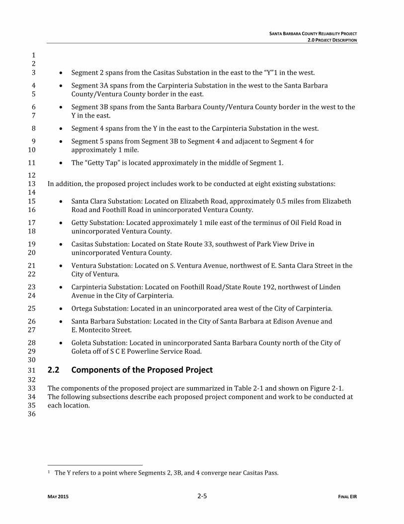
Segment2spansfromtheCasitasSubstationintheeasttothe“Y”1inthewest.3
Segment3AspansfromtheCarpinteriaSubstationinthewesttotheSantaBarbara4County/VenturaCountyborderintheeast.5
Segment3BspansfromtheSantaBarbaraCounty/VenturaCountyborderinthewesttothe6Yintheeast.7
Segment4spansfromtheYintheeasttotheCarpinteriaSubstationinthewest.8
Segment5spansfromSegment3BtoSegment4andadjacenttoSegment4for9approximately1mile.10
The“GettyTap”islocatedapproximatelyinthemiddleofSegment1.11
12Inaddition,theproposedprojectincludesworktobeconductedateightexistingsubstations:1314
SantaClaraSubstation:LocatedonElizabethRoad,approximately0.5milesfromElizabeth15RoadandFoothillRoadinunincorporatedVenturaCounty.16
GettySubstation:Locatedapproximately1mileeastoftheterminusofOilFieldRoadin17unincorporatedVenturaCounty.18
CasitasSubstation:LocatedonStateRoute33,southwestofParkViewDrivein19unincorporatedVenturaCounty.20
VenturaSubstation:LocatedonS.VenturaAvenue,northwestofE.SantaClaraStreetinthe21CityofVentura.22
CarpinteriaSubstation:LocatedonFoothillRoad/StateRoute192,northwestofLinden23AvenueintheCityofCarpinteria.24
OrtegaSubstation:LocatedinanunincorporatedareawestoftheCityofCarpinteria.25
SantaBarbaraSubstation:LocatedintheCityofSantaBarbaraatEdisonAvenueand26E.MontecitoStreet.27
GoletaSubstation:LocatedinunincorporatedSantaBarbaraCountynorthoftheCityof28GoletaoffofSCEPowerlineServiceRoad.29
302.2 Components of the Proposed Project 3132ThecomponentsoftheproposedprojectaresummarizedinTable2‐1andshownonFigure2‐1.33Thefollowingsubsectionsdescribeeachproposedprojectcomponentandworktobeconductedat34eachlocation.3536
1 TheYreferstoapointwhereSegments2,3B,and4convergenearCasitasPass.

SANTA BARBARA COUNTY RELIABILITY PROJECT
2.0 PROJECT DESCRIPTION
MAY 2015 2‐6 FINAL EIR
2.2.1 66‐kV Subtransmission Lines 12Theproposedprojectwouldincludethereconstructionofexisting66‐kVsubtransmissionline3elementsprimarilywithinexistingROWsoperatedbytheapplicant,alongthesixdifferent4segmentsidentifiedinSection2.1.ThesesegmentsareshownonFigure2‐1anddescribedbelow.56Table 2‐1 Approximate Dimensions and Specifications of Components of the Proposed
Project Component Dimensions Proposed Project Specifications
66‐kV Segments Segment1 9miles Structurestoberemoved:Foundationsatupto15LST
locations. Structurestoretrofit:1TSP. Othercomponentstobeinstalled:newfittingsto
accommodatetelecommunicationscableonthreeexistingLST;automationequipmentonanexistingTSP;poleswitchonanexistingwoodpole,andmarkerballsonoverheadwirewherenecessary.
Segment2 4.1miles Structurestoberemoved:Foundationsatupto15LSTlocations.
Othercomponentstobeinstalled:automationequipmentononeTSP;newfittingstoaccommodatetelecommunicationcableononeLST;markerballsonoverheadwirewherenecessary.
Segment3A 3.7miles Structurestoberemoved:17toppedsubtransmissionwoodpoles.
Transferof16‐kVlineandtelecommunicationslinetoexistingLWSpoles.
Othercomponentstobeinstalled:2.3milesofFRConexistingLWSpoles.
Segment3B 5.2miles Structurestoberemoved:31LST,existingconductor Structurestobeinstalled:21TSP,1LWS. Othercomponentstobeinstalled:new954ACSR
conductor(27,500feet);markerballsonoverheadwirewherenecessary.
TwoportionsofSegment3B,totaling6,300feet,wouldbemovedfromthecurrentalignmentandconstructedinnewROW.
Inaddition,aminorshifttothenortheast,primarilyaffectingtheoverhangofthenewconductorsofthe66kVsubtransmissionlinealignment,mayberequiredforanapproximate3,700‐footportionofSegment3Binordertoaddressageotechnicalconcern.
Segment4 10.8miles Structurestoberemoved:74LST,1woodH‐frame,7woodpoles,existingconductor.
Structurestobeinstalled:59TSP,4J‐Tower,1LWS. Othercomponentstobeinstalled:newdouble‐circuit954
ACSRconductor(57,000feet);markerballsonoverheadwirewherenecessary.
Segment5 11,000feet(2.08milesapprox.)
Structurestoberemovedonexisting66‐kVline:12LST,2WoodH‐frames,11,000feetofconductor(betweenSegments3Band4).

SANTA BARBARA COUNTY RELIABILITY PROJECT
2.0 PROJECT DESCRIPTION
MAY 2015 2‐7 FINAL EIR
Table 2‐1 Approximate Dimensions and Specifications of Components of the Proposed Project
Component Dimensions Proposed Project Specifications GettyTap 900feet Structurestoberemoved:4woodH‐frames,3wood
poles,existingconductor,andthreeswitches. Structurestobeinstalled:2TSP,4LWSH‐frames,3LWS. Othercomponentstobeinstalled:threeswitchesand
associatedautomationequipment,900feetof653ACSRconductorfromthetaplocationtoanexisting66‐kVsubtransmissionline.
Substations SantaClara N/A Modificationstothe66‐kVswitchrackandwithinthe
communicationsroom.Carpinteria 1,150feet Modificationstothe66‐kVswitchrackandwithinthe
MEER. Structurestoberemoved:3LST,2woodpoles,3switches. Structurestobeinstalled:3TSP. Conductorinstallationandrealignment:1,200feetof954
SACtoberoutedandconnectedtoexisting66‐kVswitchrack.
Casitas 130feet(ductbanks)
Modificationstothe66‐kVswitchrackandwithintheMEER.
Structurestobeinstalled:1TSP. Conductorinstallationandrealignment:twoductbanks
(eightconduits,130feetintotal).OtherSubstations(Getty,Goleta,Ortega,andSantaBarbaraSubstations)
N/A Componentstobeinstalled:upgradedlineprotectionrelayequipmentwithinexistingsubstationequipmentroomsorcabinets.
Telecommunications TelecommunicationrouteandEquipment
24miles Installnewtelecommunicationcableon66‐kVsubtransmissionstructuresalongSegments1,2,and4,whichwilltransitiontoanundergroundconfigurationwhenthecableentersSantaClara,CasitasandCarpinteriasubstations.
Lessthan0.7inchesindiameter. NewterminalequipmenttobeinstalledatCarpinteria,
Casitas,SantaClara,andVenturasubstations.

SANTA BARBARA COUNTY RELIABILITY PROJECT
2.0 PROJECT DESCRIPTION
MAY 2015 2‐8 FINAL EIR
Table 2‐1 Approximate Dimensions and Specifications of Components of the Proposed Project
Component Dimensions Proposed Project Specifications De‐energizing Structures Retired66‐kVsubtransmissionlinesections
Multiplesegmentsofconductors
Approximately6,500feetof336ACSRwouldbede‐energizedbetweenSantaClaraSubstationandtheGettyTapinSegment1.
Approximately49,200feetof2/0barecopperconductorwouldbede‐energizedbetweenalocationapproximately1milefromSantaClaraSubstationtheGettyTapandCasitasSubstationinSegment1.
Approximately16,300feetof2/0barecopperconductorwouldbede‐energizedontheSantaClara–Getty66‐kVsubtransmissionLineinSegment3B.
Approximately12,000feetof653ACSRand8,500feetof2/0barecopperconductorwouldbeidledinandadjacenttoSegment4.
Approximately24,200feetof2/0barecopperconductorand17,600feetof653ACSRwouldbede‐energizedinSegment4.
Removal of Additional Structures Privateirrigationstructures
TBD Removalorrelocationtobedeterminedcase‐by‐casewithlandowners.
Access and Spur Roads Rehabilitationand/orupgradestoexistingaccess/spurroadsandconstructionofnewspurroads
120miles Structurestobeinstalled:retainingwall‐typestructurestominimizedisturbanceinsomelocations.
Source:SCEdocumentationsubmitted2012‐2014Key:ACSR aluminumconductorsteel‐reinforcedFRC faultreturnconductorkV kilovoltLST latticesteeltowerLWS lightweightsteelpoleMEERmechanicalelectricalequipmentroomN/A notapplicableROW right‐of‐waySACstrandedaluminumconductorTBD tobedeterminedTSP tubularsteelpole12.2.1.1 Segment 1 23Segment1originatesattheSantaClaraSubstationandterminatesattheCasitasSubstation,witha4totallengthofapproximately9mileswithinunincorporatedareasofVenturaCounty.InSegment1,5theapplicantwould:67
Removefoundationsatupto15latticesteeltower(LST)locationstoapproximately2feet8belowgrade,exceptinplaceswhereremovalcouldresultinerosionproblemsorlandowner9concerns.10

SANTA BARBARA COUNTY RELIABILITY PROJECT
2.0 PROJECT DESCRIPTION
MAY 2015 2‐9 FINAL EIR
Retrofitonetubularsteelpole(TSP)toaccommodatenewtelecommunicationscable.1
InstallnewfittingstoaccommodatethetelecommunicationscableonthreeLSTs.2
InstallautomationequipmentonanexistingTSP.3
Replaceapoleswitchonasinglewoodpole.4
Installmarkerballsonoverheadwirewheredeterminednecessary.562.2.1.2 Segment 2 78Segment2originatesattheCasitasSubstationandterminatesattheY,inunincorporatedVentura9County.ThelengthofSegment2isapproximately4.1miles.InSegment2,theapplicantwould:1011
Removefoundationsatupto15LSTlocationstoapproximately2feetbelowgrade,except12inplaceswhereremovalcouldresultinerosionproblemsorlandownerconcerns.13
InstallautomationequipmentonanexistingTSP.14
InstallnewfittingstoaccommodatetelecommunicationscableononeLST.15
Installmarkerballsonoverheadwirewheredeterminednecessary.16172.2.1.3 Segment 3A 1819Segment3AoriginatesattheCarpinteriaSubstation,locatedintheCityofCarpinteria,and20terminatesattheborderofSantaBarbaraCountyandVenturaCounty.ThelinearlengthofSegment213Aisapproximately3.7miles,withconductorspansthatrangefrom105to425feetinlength.In22Segment3A,theapplicantwould:2324
Relocateexisting16‐kVdistributioncircuitsandthird‐partytelecommunicationsfacilities25thatarecollocatedontopped2woodpolestoadjacentexisting66‐kVlightweightsteel26(LWS).27
Installapproximately2.3milesoffaultreturnconductorontheexisting66‐kVLWSpoles.28
Remove17existingtoppedsubtransmissionpoles,includingsixpolescontainingdistributionand29communicationfacilitiesthatwouldbetransferredtoexisting66‐kVLWSpoles,fivesixpoles30containingthird‐partyfacilitiesthatwouldbetransferredbytheapplicantorthethird‐partyowner,31andfourfiveexistingwoodpolesthatcontainnoequipment.32332.2.1.4 Segment 3B 3435Segment3BoriginatesattheSantaBarbaraCounty/VenturaCountylineandterminatesattheYin36unincorporatedVenturaCounty,withalengthofapproximately5.2miles.Theconductorspans37alongSegment3Brangefromapproximately250to2,500feetinlength.InSegment3B,the38applicantwould:3940
2 “Topped”referstoapolestructurewheretheupperportionhasbeenremoved(reducingitsoverallheight)aftertheconductororcircuitsinstalledonthatportionofthepolehavebeenretired.Theremaininglowerportionofthestructurewouldcontinuetosupporttheelectricpowercircuitorthirdpartyfacility.

SANTA BARBARA COUNTY RELIABILITY PROJECT
2.0 PROJECT DESCRIPTION
MAY 2015 2‐10 FINAL EIR
Replaceapproximately31LSTsandassociatedstructureswithapproximately21TSPsand1oneLWSpole.2
Removedupto31LSTfoundations.RemoveexistingLSTfoundationsto2feetbelow3groundsurface,exceptinareaswhereremovalcouldresultinerosionproblemsor4landownerconcerns.5
Removetheexistingconductorandinstallapproximately27,500feetofsingle‐circuit9546aluminumconductorsteel‐reinforced(ACSR)cable.7
MoveapproximatelytwoportionsofSegment3B,totaling6,300linearfeetfromthecurrent8alignmenttonewROWtoavoidgeotechnicalconcerns.9
Installmarkerballsonoverheadwireswheredeterminednecessary.10112.2.1.5 Segment 4 1213Segment4originatesattheY(unincorporatedVenturaCounty)andterminatesattheCarpinteria14Substation(CityofCarpinteria,SantaBarbaraCounty),withalengthofapproximately10.8miles.15TheconductorspansalongSegment4rangefromapproximately110to1,800feetinlength.In16Segment4,theapplicantwould:17 18
Replaceapproximately74LSTs,onewoodH‐frame,andsevenwoodpoleswith19approximately59TSPs,4J‐Towers,andoneLWSpole.20
Removethenecessaryconductorandinstallapproximately57,000feetofdoublecircuit95421ACSRwire.22
Removetwopoleswitches.23
RemoveexistingLSTfoundationsto2feetbelowgroundsurface,exceptinareaswhere24removalcouldresultinerosionproblemsorlandownerconcerns.25
InstalltelecommunicationcableonallTSPsandJ‐Towers.26
Installmarkerballsonoverheadwireswheredeterminednecessary.2728Ofthestructuresdescribedabove,twoexistingstructuresandseveralaccessandspurroad29segmentsarelocatedonUSForestService(USFS)managedlandwithintheLosPadresNational30Forest.WorkwithintheLosPadresNationalForestwouldinvolvetheremovalandreplacementof31existingstructureswithnewTSPsorJ‐Tower,removalandreplacementofconductor,and32improvementstoexistingaccessandspurroads,resultinginapproximately2.4acresofdisturbance33withintheLosPadresNationalForest.3435Ofthestructuresdescribedabove,1822existingstructuresandanumberofaccessandspurroad36segmentsarelocatedwithintheSantaBarbaraCountyCoastalZone.WorkwithintheCoastalZone37wouldinvolvetheremovalandreplacementofexistingstructureswithnewTSPs,removaland38replacementofconductor,andimprovementstoorconstructionofnewaccessandspurroads,39resultinginapproximately1.49acresofpermanentdisturbanceand4.02acresoftemporary40disturbance.Oneofthe1822structures,anditsassociatedspurroad,iscollocatedwithintheLos41PadresNationalForest.4243
44

SANTA BARBARA COUNTY RELIABILITY PROJECT
2.0 PROJECT DESCRIPTION
MAY 2015 2‐11 FINAL EIR
2.2.1.6 Segment 5 12Theproposedprojectalsoinvolvestheremovalof12existingLSTs,twowoodH‐framestructures,3andapproximately11,000feetofconductorduetotheirlocationonunstableslopes.These4structuresarelocatedbetweenSegments3Band4andadjacenttoSegment4forapproximately51mile.Structureswouldbeaccessedusingexistingaccessroads.Thestructureswouldberemoved6usingthesametechniquesasdescribedaboveinSection2.3.2.6,“TransferandRemovalofExisting7Structures/Facilities.”Thisareaislabeledas“Segment5”ExistingSubTrans66‐kVToBeRemoved8onFigure2‐1.Nonewstructureswouldbeconstructed.9102.2.1.7 Structures 1112Theproposed66‐kVsubtransmissionlineswouldbebuiltusingLWSpoles,LWSH‐frames,13J‐Towers,andTSPs(Figure2‐2).ThesestructureswouldbedesignedconsistentwiththeSuggested14PracticesforRaptorProtectiononPowerLines:theStateoftheArtin2012(APLIC2012).Figure152‐2showsaschematicofeachproposedstructure,andTable2‐2summarizesthenumberand16dimensionsofstructuresproposedtobeinstalled.1718Table 2‐2 Proposed Structures to be Installed
Pole Type
Approximate Number of Proposed Structures
Approximate Height Above Ground (feet)
Approximate Pole Diameter
(feet)
Approximate Auger Hole Depth (feet)
Approximate Auger
Diameter (feet)
TSP 85 55–145 4–6atbase 15–70 5–9LWSPole 5 60–85 1–2atbase 9–11 2–2.5LWSH‐Frame
6 60–70 1–2atbase 9–11 2–2.5
J‐Tower 4 77‐135 n/a n/a n/aGuyPole Lessthan10 25–40 1–2atbase 9–11 2–2.5Source:SCEdocumentationsubmitted2012‐2014Notes:PoleheightsandspacingwouldbedetermineduponfinalengineeringandwouldbeconstructedincompliancewithCPUCGO95.StructurecountincludesonlythosestructuresthatwouldbepermanentlyinstalledinSegments3A,3B,and4,attheGettyTapsegment,andatCarpinteriaSubstationandCasitasSubstation.Temporarystructuresarenotincluded.Key:CPUC CaliforniaPublicUtilitiesCommissionGO GeneralOrderLWS lightweightsteeln/a notapplicableTSP tubularsteelpole19202122

SANTA BARBARA COUNTY RELIABILITY PROJECT
2.0 PROJECT DESCRIPTION
MAY 2015 2‐12 FINAL EIR
Figure 2‐2 Proposed 66‐kV Subtransmission Structures
Source:SCE2012

SANTA BARBARA COUNTY RELIABILITY PROJECT
2.0 PROJECT DESCRIPTION
MAY 2015 2‐13 FINAL EIR
Tubular Steel Pole 1
Approximately85TSPswouldbeinstalledfortheproposedproject,primarilyinSegments3Band24.TheTSPswouldbeapproximately4to6feetindiameteratthebaseandextendapproximately355to145feetaboveground,notincludingtheabove‐groundheightofthefoundation.TheTSPs4wouldbeattachedtoconcretefoundationsapproximately5to9feetindiameterandwouldextend5undergroundapproximately15to70feet,withaprojectionofapproximately2to4feetofconcrete6aboveground.TSPfootingswoulduseapproximately11to175cubicyardsofconcretedepending7uponthediameteranddepthofthefooting.TheTSPswouldbeall‐steelstructureswithadulled8finish.TSPstobeinstalledinSegment4andattheCarpinteriaSubstationwouldbeequippedwith9fittingstoaccommodatetelecommunicationscable.1011Lightweight Steel Pole 12
ApproximatelyfiveLWSpoleswouldbeinstalledaspartoftheproposedproject.LWSpoleswould13notrequireconcretefootings(directburied)andwouldextendapproximately60to85feetabove14ground.ThediameteroftheLWSpoleswouldtypicallybe1to2feetatgroundlevel,taperingtothe15topofthepole.1617Lightweight Steel Pole H‐Frame 18
ApproximatelysixH‐framesconstructedfromLWSpoleswouldbeinstalledfortheproposed19project.Inaddition,theproposedprojectwouldusetwopreviouslyinstalledLWSH‐frames.The20LWSH‐frameswouldbedirect‐buriedandextendapproximately60to70feetaboveground.The21diameteroftheLWSpoleswouldtypicallybe1to2feetatgroundlevel,taperingtothetopofthe22pole.2324J‐Tower 25
FourJ‐TowerswouldbeinstalledalongSegment4aspartoftheproposedproject.SCEcurrently26usesJ‐TowersasanalternativewhereusingaTSPisimpractical(e.g.,wheresiteaccessis27constrained,thusnecessitatinghelicopter‐assistedconstruction,assemblyofsectionsoff‐site,and28thenfinalassemblyofsectionsbyhandon‐site;orwhereduetoengineeringissuestheuseofaTSP29wouldbeproblematic).TheJ‐Towerrequiresfourfootingstobeplacedinasquareapproximately3030feetapart.TheJ‐Towerstructureswouldrangeinheightfrom77to135feet.TheuseofJ‐31Towersatspecificconstructionsitesoftheproposedprojectwould,duetosite‐specificconditions,32allowSCEtoreducegrounddisturbanceattheseconstructionsitesthroughthereductioninsizeor33eliminationofspurroads,retainingwalls,andconstructionpads.3435Guying and Guy Pole 36
Aguyisatensionedcabledesignedtoaddstabilitytoafree‐standingstructure.Fewerthan10guy37wirescouldbeattachedtosubtransmissionstructuresalongSegments3Band4.Guyingconsistsof38aguywire(downguy)attachedtoaburiedanchor,or,whenthereisnotadequatespaceforthe39requireddownguy,ashorterguypole(stubpole)istypicallyplacedwithadownguyandburied40anchorinalocationthathassufficientroomforthesefacilities.Theheight,depth,anddiameterof41stubpolesandguywireanchorswouldbedeterminedonacase‐by‐casebasis.4243Temporary Guard Structures 44
Guardstructuresaretemporaryfacilitiesthatmaybeinstalledattransportation,floodcontrol,and45utilitycrossingsforwirestringing/removalactivities.Thesestructuresaredesignedtostopthe46

SANTA BARBARA COUNTY RELIABILITY PROJECT
2.0 PROJECT DESCRIPTION
MAY 2015 2‐14 FINAL EIR
movementofaconductorshoulditmomentarilydropbelowaconventionalstringingheight.If1used,guardstructureswouldbetemporarilyinstalledoneachsideofallpublicroadcrossingsand2whereinstallationofthe66‐kVsubtransmissionlinecrossesotherutilitiesalongtheroute.Guard3structurescouldalsobetemporarilyinstalledoneachsideofdrivewaysandprivateroadsthatare4crossed,wherenecessary.Guardstructureswouldbeconstructedonsiteusingwoodpolesand5thenremovedafterconstructioniscomplete.Insomecases,specificallyequippedboomtrucks6couldbesubstitutedforguardstructuresbecausetheywouldalreadybelocatedatthesitefor7generalconstructionactivities.Decisionsregardingwhethertouseguardstructuresorboom8truckswouldbedeterminedduringconstruction.9102.2.1.8 Insulators and Conductors 1112Theapplicantwouldinstallapproximately27,500feetofsinglecircuitand57,000linearfeetofnew13doublecircuit954ACSRconductorandpolymerinsulatorsoneachproposedoverheadstructure14alongSegments3Band4.OntheGettyTapsegment,approximately900feetof653ACSRwouldbe15installed.Allconductorwouldbenon‐specular.1617Fault Return Conductor 18
AlthoughtheexistingandproposedLWSpolesareearth‐groundedstructures,theapplicantwould19provideadditionalfaultprotectionbyinstallingafaultreturnconductor(FRC)alongapproximately2012,000feet(2.3miles)ofSegment3A.ThisconductorwouldelectricallygroundtheLWSpoles.The21purposeofgroundfaultprotectionistominimizepotentialdamagestoequipmentandhazardsfor22personnelandthepublicduetogroundfaultcurrents.2324Federal Aviation Administration Requirements 25
ThealignmentofthelinesandterrainintheregionwouldrequirethattheFederalAviation26Administration(FAA)benotifiedduetotheabove‐groundheightoftheconductoror27telecommunicationscablebetweentowers.TheapplicantwouldfilethenecessaryFAAForm746028forstructuresorlinesasoutlinedinCodeofFederalRegulationsTitle14Part77,uponcompletion29offinalengineeringandpriortoconstruction.AllFAArecommendationswouldbeimplemented30intothedesignoftheproposedproject.3132Ifaspanrequiredthreeorfewermarkerballs,thenthemarkerballsonthespanwouldallbe33aviationorange.Ifaspanrequiredmorethanthreemarkerballs,thenthemarkerballswould34alternatebetweenaviationorange,white,andyellow.Markerballswouldbe36inchesindiameter.35362.2.1.9 Underground Subtransmission Facilities 3738UndergroundsubtransmissionfacilitieswouldtransitionthepreviouslyconstructedSegment1and39Segment2overheadlinesthroughtwoexistingductbanksintotheCasitasSubstation.Oneduct40bankwouldbeapproximately50feetlong,andtheotherwouldbeapproximately80feetlong,fora41totalof130feet.Eachductbankwouldhousethreecopperundergroundsubtransmissioncables42(3,000kcmil3),whichwouldbe225feetand175feetinlength,respectively.Thecablelengthsare433 Acircularmil(cmil)isastandardunitofmeasureusedforelectricalsystemsthatreferstotheareaofthecrosssectionoflargerconductorsizes.Onecmilisequaltotheareaofacirclewitha1‐mildiameter,and1kcmilisequalto1,000cmils.Largeconductorsizesratedforuseonelectricaltransmissionlinesaregenerally0.6to2inchesindiameter.A3,000‐kcmilconductorisapproximately2inchesindiameter.Ingeneral,alargerdiameterconductoriscapableofgreaterelectricalcarryingcapacitythanasmaller
SANTA BARBARA COUNTY RELIABILITY PROJECT
2.0 PROJECT DESCRIPTION
MAY 2015 2‐15 FINAL EIR
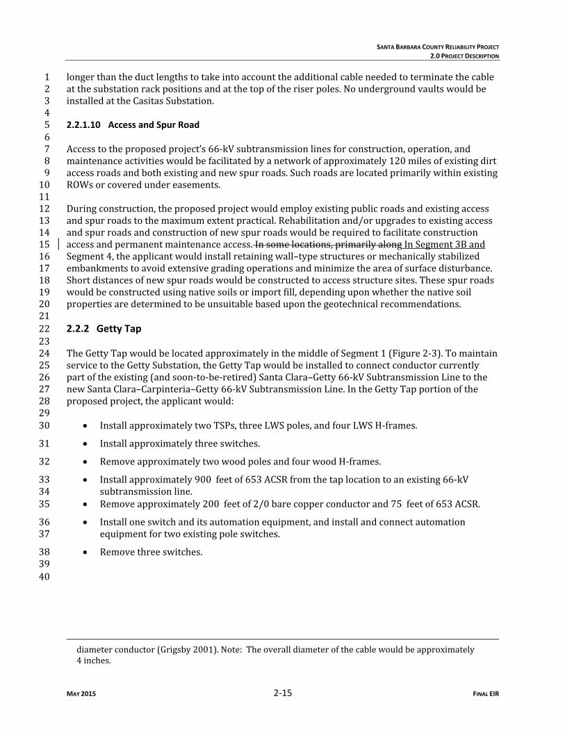
longerthantheductlengthstotakeintoaccounttheadditionalcableneededtoterminatethecable1atthesubstationrackpositionsandatthetopoftheriserpoles.Noundergroundvaultswouldbe2installedattheCasitasSubstation.342.2.1.10 Access and Spur Road 56Accesstotheproposedproject’s66‐kVsubtransmissionlinesforconstruction,operation,and7maintenanceactivitieswouldbefacilitatedbyanetworkofapproximately120milesofexistingdirt8accessroadsandbothexistingandnewspurroads.Suchroadsarelocatedprimarilywithinexisting9ROWsorcoveredundereasements.1011Duringconstruction,theproposedprojectwouldemployexistingpublicroadsandexistingaccess12andspurroadstothemaximumextentpractical.Rehabilitationand/orupgradestoexistingaccess13andspurroadsandconstructionofnewspurroadswouldberequiredtofacilitateconstruction14accessandpermanentmaintenanceaccess.Insomelocations,primarilyalongInSegment3Band15Segment4,theapplicantwouldinstallretainingwall–typestructuresormechanicallystabilized16embankmentstoavoidextensivegradingoperationsandminimizetheareaofsurfacedisturbance.17Shortdistancesofnewspurroadswouldbeconstructedtoaccessstructuresites.Thesespurroads18wouldbeconstructedusingnativesoilsorimportfill,dependinguponwhetherthenativesoil19propertiesaredeterminedtobeunsuitablebaseduponthegeotechnicalrecommendations.20212.2.2 Getty Tap 2223TheGettyTapwouldbelocatedapproximatelyinthemiddleofSegment1(Figure2‐3).Tomaintain24servicetotheGettySubstation,theGettyTapwouldbeinstalledtoconnectconductorcurrently25partoftheexisting(andsoon‐to‐be‐retired)SantaClara–Getty66‐kVSubtransmissionLinetothe26newSantaClara–Carpinteria–Getty66‐kVSubtransmissionLine.IntheGettyTapportionofthe27proposedproject,theapplicantwould:2829
InstallapproximatelytwoTSPs,threeLWSpoles,andfourLWSH‐frames.30
Installapproximatelythreeswitches.31
RemoveapproximatelytwowoodpolesandfourwoodH‐frames.32
Installapproximately900feetof653ACSRfromthetaplocationtoanexisting66‐kV33subtransmissionline.34
Removeapproximately200feetof2/0barecopperconductorand75feetof653ACSR.35
Installoneswitchanditsautomationequipment,andinstallandconnectautomation36equipmentfortwoexistingpoleswitches.37
Removethreeswitches.3839
40
diameterconductor(Grigsby2001).Note:Theoveralldiameterofthecablewouldbeapproximately4inches.
SANTA BARBARA COUNTY RELIABILITY PROJECT
2.0 PROJECT DESCRIPTION
MAY 2015 2‐16 FINAL EIR
2.2.3 Substations 1 22.2.3.1 Santa Clara 34TheSantaClaraSubstationcontainsboth220‐kVand66‐kVequipment.Theproposedproject5wouldinvolveonlymodificationstothe66‐kVequipment.WorkattheSantaClaraSubstation6wouldoccuronthe66‐kVswitchrackandwithinthecommunicationsroom.Thetwo66‐kV7operatingbusesattheSantaClaraSubstationcurrentlyhave30positions.89Thefollowingworkwouldbeconductedatthreepositionsaspartoftheproposedproject:1011
Sixnewpotentialtransformers(PTs)andtheirassociatedfoundationswouldbeinstalled:a12setoftwoPTsforeachofthethreelinepositions.13
Newprotectionequipmentwouldbeinstalledforthethreelinepositions.14
Circuitbreakers,group‐operateddisconnects,otherassociatedequipment(includingnew15foundations),and200feetof2/0barecopperconductorwouldberemovedfromoneline16position.17
18Followingtheupgradestothe66‐kVpositions,subtransmissionlineswouldberetired,removed,19and/orreconfigured.20212.2.3.2 Casitas 2223WorkrelatedtotheproposedprojectattheCasitasSubstationwouldoccuronthe66‐kV24switchrackandwithintheMechanicalElectricalEquipmentRoom(MEER).Asdiscussedabovein25Section2.2.1.8,fFollowingmodificationstothe66‐kVpositions,bothsubtransmissionlinesthat26enterthesubstationwouldberoutedthroughnewundergroundconduittotheswitchrack,andthe27overheadconductorwouldberemoved.Theproposedprojectwould:2829
Modifytheexistingthe66‐kVswitchrackbyinstalling12surgearresters(threeoneach30operatingandtransferbusandthreeoneachlineposition);newgroup‐operated31disconnectsandnewfoundationsatonelineposition;andnewprotectionequipmentfor32twolinepositions.33
Installandrealign66‐kVsubtransmissionconductorwithinandinproximitytotheCasitas34Substation.Toaccommodatethisrealignment,oneTSPwouldbeinstalledontheeastern35portionofthesubstationpropertyoutsidethesubstationfence.36
ConnectexistinglinestothenewTSPandinstallnewundergroundcablestofacilitate37circuitre‐arrangementinsidethesubstation.38
Installtwoductbanksconsistingoffour5‐inchconduitseach(atotalofeightconduits)on39theapplicant’spropertybothwithinandoutsidethesubstationfencefromthebaseofthe40newTSPtotheexistingcircuitbreakersattwopositions.Atotalofapproximately130feet41ofductintwoductbankswouldbeinstalled.Eachsubtransmissioncablewouldbeplacedin42aconduitandthenconnectedtotheappropriate66‐kVposition.43
44

\\Prtbhp1\gis\SanFrancisco\SantaBarbaraCoReliability\Maps\MXDs\Report_Maps\Figure2_3_Getty_Tap_Overview_Update.mxd February 2014
AZ
CA
ID
NV
OR
UT
Existing ElectricalSubtransm ission Lines
Segm ent 1Segm ent 2Existing 66-kV Subtransm issionLines to be Rem oved
Getty Tap Cond uctorOther SCE Facilities
! Existing Substation Locations
!(G Getty Tap!( Proposed New Structure Location
#* Existing Structures to be rem oved) Found ations To Be Rem oved
Existing Access/Spur RoadMajor Road sCity Lim itsLos Pad res National Forest (USFS)Bio Preserve AreasCoastal Com m ission Zone
Santa Barbara CountyReliability Project
Santa Barbara andVentura Counties
California
Figure 2-3Getty Tap
")") ") ")
!( !(
#
#
### #*#
*#
*#*#*# *#
!!!
! !
!
!
(((
( (
(
(
Santa
Clar
a –Ca
sitas-T
ayshe
ll 66-k
V Sub
transm
ission
Line
Santa Clara- Getty 66-kV Subtransm ission Line (To be Id led )
Goleta-Santa Clara #1 220-kV Transm ission Line
LWSLWSLWS
LWS
TSP
TSP
LWS
!(G
L A K EL A K EC A S I T A SC A S I T A S Ventura Co.
GETTY SANTACLARA
CASITAS
VENTURA£¤101
£¤118
£¤33
£¤126
£¤150
San Buenaventura(Ventura)
O ja iMira
Mo nte
0 200Feetº
º0 2
Miles

SANTA BARBARA COUNTY RELIABILITY PROJECT
2.0 PROJECT DESCRIPTION
MAY 2015 2‐18 FINAL EIR
12.2.3.3 Carpinteria 23AttheCarpinteriaSubstation,workwouldoccuronthe66‐kVswitchrackandwithintheMEER.4Theproposedprojectwould:56
Modifytheexisting66‐kVswitchrackbyextendingthe66kVtransferbusbyonepositionto7createanewlineposition.8
Increasethecapacityofthe66‐kVoperatingandtransferbusesinstalling1590ACSR,which9willinvolvereplacingallexistingporcelaininsulatorsonthe66‐kVswitchrackwith10polymer‐typeinsulators;installingthreesurgearrestersonthe66kVoperatingbusand11threesurgearrestersonthetransferbus;installingnewgroup‐operateddisconnects(and12newfoundations)atonenewandfourexistingpositions;installingfivenewcircuit13breakers(andnewfoundations);installingPTs(andnewfoundations)atonenewandthree14existinglinepositions;andinstallingnewsurgearrestersatfourpositions;installingnew15protectionequipmentforfourlineandbustiepositions.16
17Followingthemodificationtothe66kVswitchrack,thesubtransmissionlinesroutedinandoutof18thesubstationwouldberealignedandupgradedfrom653ACSRto954SAC.Approximately1,10019feetof653ACSRwouldberemoved,and1,200feetof954SACwouldberoutedoverheadand20connectedtothe66‐kVswitchrack.Inaddition,a66‐kVstationswitchandthreesubtransmission21lineswitcheslocatedinthesubstationwouldberemoved.Toaccommodatetheseupgrades,three22existingLSTsandtwowoodpolesinsidethesubstationfencelinewouldbereplacedwiththree23TSPs.24252.2.3.4 Other Substations 2627WorkproposedattheGettySubstation,GoletaSubstation,OrtegaSubstation,andSantaBarbara28Substationwouldincludetheinstallationofupgradedlineprotectionrelayequipmentwithin29existingsubstationequipmentroomsorcabinetsonthesubstationsites.30312.2.4 Telecommunications 3233TelecommunicationscablewouldbeinstalledatornearthetopofoverheadstructuresinSegments341,2,and4.Pullingandsplicinglocationswouldbethesameasthoseusedforinstallationof35subtransmissionconductor.Thepurposeoftheproposedtelecommunicationinfrastructureisto36connecttheexistingtelecommunicationssystemoperatedbytheapplicantandwouldprovide37SupervisoryControlandDataAcquisition(SCADA),protectiverelaying,datatransmission,and38telephoneservicesfortheproposedprojectandassociatedfacilities.Anewtelecommunications39routeisrequiredtoconnecttheCarpinteriaSubstation,CasitasSubstation,SantaClaraSubstation,40andVenturaSubstation.TheconnectionbetweentheVenturaSubstationandSantaClaraSubstation41woulduseexistingtelecommunicationsfacilities.AllworkconductedattheVenturaSubstation42wouldoccurwithintheMEERandwouldnotincludeanyground‐disturbingactivities.43442.2.4.1 Fiber Optic Lines and Telecommunications Equipment 4546Approximately127,000feet(approximately24miles)ofnewtelecommunicationcablewouldbe47installedon66‐kVsubtransmissionstructuresinSegments1,2,and4,connectingtheCarpinteria48

SANTA BARBARA COUNTY RELIABILITY PROJECT
2.0 PROJECT DESCRIPTION
MAY 2015 2‐19 FINAL EIR
Substation,CasitasSubstation,andSantaClaraSubstation.Thecablewouldbeapproximately0.71inchesindiameter.23Asmentionedabove,mostofthetelecommunicationscablewouldbeinstalledoverheadon4subtransmissionstructures,abovethesubtransmissionconductor.Shortsegmentswouldbe5installedundergroundinconduitasthetelecommunicationscableentersandexitstheCarpinteria,6Casitas,andSantaClaraSubstations.Inadditiontotheundergroundworkatthesubstations,new7relayswouldbeinstalledintheexistingMEERsattheCarpinteriaSubstationandCasitas8Substation,andinthecommunicationsroomattheSantaClaraSubstation.910Newterminalequipment,channelmultiplexerequipment,equipmentcabling,andother11telecommunicationequipmentdeviceswouldbeinstalledwithintheMEERsattheCarpinteria12Substation,CasitasSubstation,andVenturaSubstation,andinthecommunicationroomattheSanta13ClaraSubstation.Thisworkwouldprovidetherequiredtelecommunicationcircuitconnectionto14subtransmissionlineprotectionrelayequipmentwithinthesubstations.15162.2.4.2 Telecommunications Route 1718AsummaryoftheproposedundergroundtelecommunicationcablefacilitiesisprovidedinTable192‐3.Approximately47,500feet(approximately9miles)oftelecommunicationscablewouldbe20installedonsubtransmissionstructuresinSegment1fromtheSantaClaraSubstationtotheCasitas21Substation.TheroutewouldoriginateinthecommunicationsroomattheSantaClaraSubstation.22Thetelecommunicationscablewouldbeinstalledundergroundinanexistingcontrolcabletrench23andthroughapproximately225feetofnewconduitfromthecommunicationsroomtothe24easternmostTSPinSegment1,whereitwouldtransitiontoanoverheadconfiguration.2526Table 2‐3 Proposed Underground Telecommunication Construction
Substation
Trench Length (feet)1,2,4
Inside Substation Area Outside Substation Area SantaClara ~80 ~145Casitas3 ~25 ~75Carpinteria ~80 0Source:SCEdocumentationsubmitted2012‐2014Source:SCE2012Notes:1Novaultswouldbeconstructedaspartoftheproposedproject.2Theapplicantcouldmodifytrenchlengthbasedonfinalengineeringdesign.3TheconduitforSegments1and2isroutedthroughthesametrenchandductbankatCasitasSubstation.
4Conduitwouldbeinstalledintrenchesthatareapproximately11incheswideand36inchesdeep.
27AttheCasitasSubstation,thetelecommunicationscablewouldtransitionfromoverheadto28underground,enteringtheMEERthroughapproximately100feetofnewconduitandtheexisting29controlcabletrench.ThetelecommunicationscablewouldexittheMEERundergroundthrougha30separateconduitwithinthesamecontrolcabletrenchandproceedtoanLSTlocatedoutsidethe31substationfence,whereitwouldtransitiontoanoverheadconfiguration.FromtheCasitas32Substation,thetelecommunicationscablewouldproceedforapproximately78,500feet33(approximately15miles)onsubtransmissionstructuresinSegments2and4totheCarpinteria34Substation.3536
SANTA BARBARA COUNTY RELIABILITY PROJECT
2.0 PROJECT DESCRIPTION
MAY 2015 2‐20 FINAL EIR
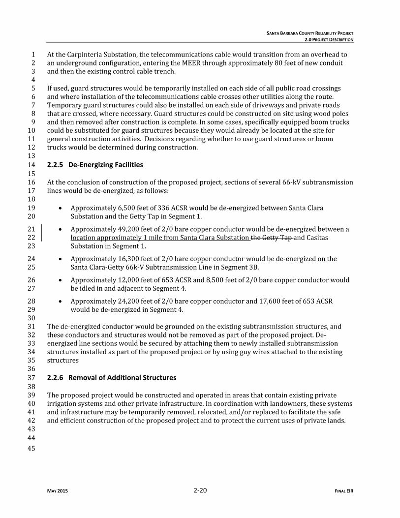
AttheCarpinteriaSubstation,thetelecommunicationscablewouldtransitionfromanoverheadto1anundergroundconfiguration,enteringtheMEERthroughapproximately80feetofnewconduit2andthentheexistingcontrolcabletrench.34Ifused,guardstructureswouldbetemporarilyinstalledoneachsideofallpublicroadcrossings5andwhereinstallationofthetelecommunicationscablecrossesotherutilitiesalongtheroute.6Temporaryguardstructurescouldalsobeinstalledoneachsideofdrivewaysandprivateroads7thatarecrossed,wherenecessary.Guardstructurescouldbeconstructedonsiteusingwoodpoles8andthenremovedafterconstructioniscomplete.Insomecases,specificallyequippedboomtrucks9couldbesubstitutedforguardstructuresbecausetheywouldalreadybelocatedatthesitefor10generalconstructionactivities.Decisionsregardingwhethertouseguardstructuresorboom11truckswouldbedeterminedduringconstruction.12132.2.5 De‐Energizing Facilities 1415Attheconclusionofconstructionoftheproposedproject,sectionsofseveral66‐kVsubtransmission16lineswouldbede‐energized,asfollows:1718
Approximately6,500feetof336ACSRwouldbede‐energizedbetweenSantaClara19SubstationandtheGettyTapinSegment1.20
Approximately49,200feetof2/0barecopperconductorwouldbede‐energizedbetweena21locationapproximately1milefromSantaClaraSubstationtheGettyTapandCasitas22SubstationinSegment1.23
Approximately16,300feetof2/0barecopperconductorwouldbede‐energizedonthe24SantaClara‐Getty66k‐VSubtransmissionLineinSegment3B.25
Approximately12,000feetof653ACSRand8,500feetof2/0barecopperconductorwould26beidledinandadjacenttoSegment4.27
Approximately24,200feetof2/0barecopperconductorand17,600feetof653ACSR28wouldbede‐energizedinSegment4.29
30Thede‐energizedconductorwouldbegroundedontheexistingsubtransmissionstructures,and31theseconductorsandstructureswouldnotberemovedaspartoftheproposedproject.De‐32energizedlinesectionswouldbesecuredbyattachingthemtonewlyinstalledsubtransmission33structuresinstalledaspartoftheproposedprojectorbyusingguywiresattachedtotheexisting34structures35362.2.6 Removal of Additional Structures 3738Theproposedprojectwouldbeconstructedandoperatedinareasthatcontainexistingprivate39irrigationsystemsandotherprivateinfrastructure.Incoordinationwithlandowners,thesesystems40andinfrastructuremaybetemporarilyremoved,relocated,and/orreplacedtofacilitatethesafe41andefficientconstructionoftheproposedprojectandtoprotectthecurrentusesofprivatelands.424344
45
SANTA BARBARA COUNTY RELIABILITY PROJECT
2.0 PROJECT DESCRIPTION
MAY 2015 2‐21 FINAL EIR
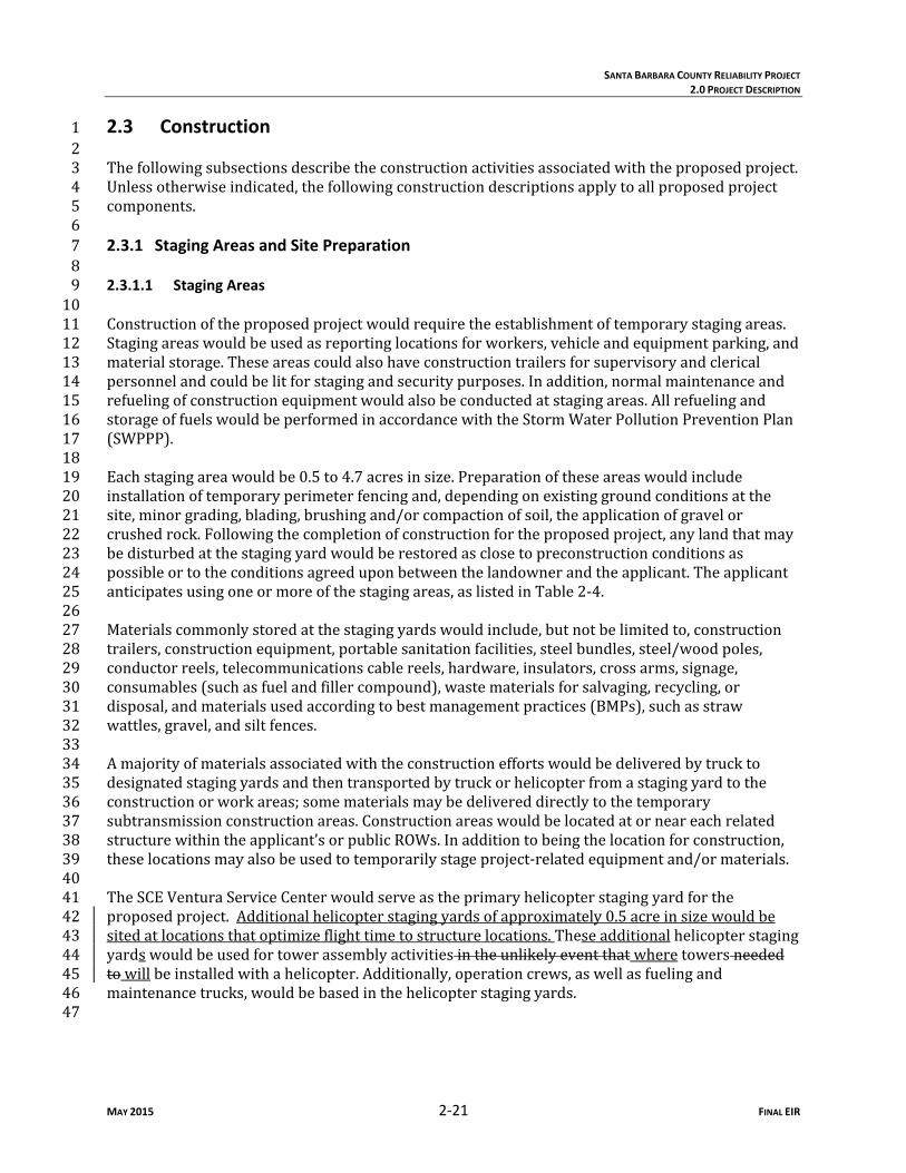
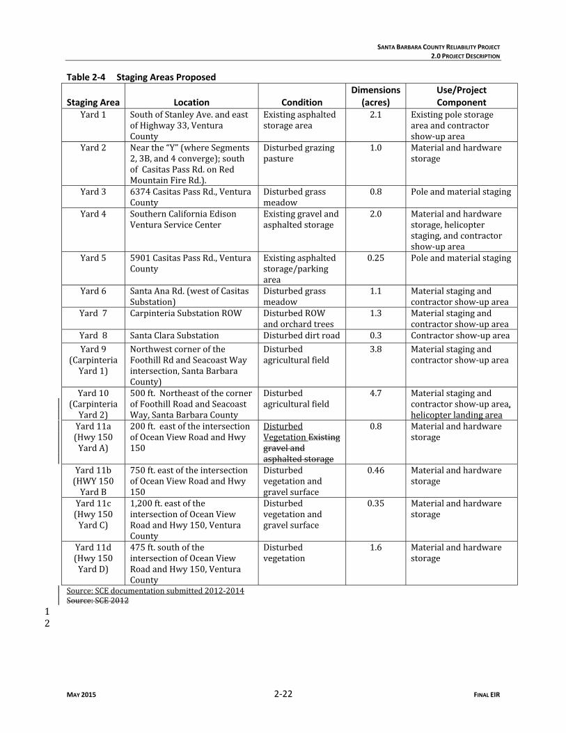
2.3 Construction 12Thefollowingsubsectionsdescribetheconstructionactivitiesassociatedwiththeproposedproject.3Unlessotherwiseindicated,thefollowingconstructiondescriptionsapplytoallproposedproject4components.562.3.1 Staging Areas and Site Preparation 782.3.1.1 Staging Areas 910Constructionoftheproposedprojectwouldrequiretheestablishmentoftemporarystagingareas.11Stagingareaswouldbeusedasreportinglocationsforworkers,vehicleandequipmentparking,and12materialstorage.Theseareascouldalsohaveconstructiontrailersforsupervisoryandclerical13personnelandcouldbelitforstagingandsecuritypurposes.Inaddition,normalmaintenanceand14refuelingofconstructionequipmentwouldalsobeconductedatstagingareas.Allrefuelingand15storageoffuelswouldbeperformedinaccordancewiththeStormWaterPollutionPreventionPlan16(SWPPP).1718Eachstagingareawouldbe0.5to4.7acresinsize.Preparationoftheseareaswouldinclude19installationoftemporaryperimeterfencingand,dependingonexistinggroundconditionsatthe20site,minorgrading,blading,brushingand/orcompactionofsoil,theapplicationofgravelor21crushedrock.Followingthecompletionofconstructionfortheproposedproject,anylandthatmay22bedisturbedatthestagingyardwouldberestoredasclosetopreconstructionconditionsas23possibleortotheconditionsagreeduponbetweenthelandownerandtheapplicant.Theapplicant24anticipatesusingoneormoreofthestagingareas,aslistedinTable2‐4.2526Materialscommonlystoredatthestagingyardswouldinclude,butnotbelimitedto,construction27trailers,constructionequipment,portablesanitationfacilities,steelbundles,steel/woodpoles,28conductorreels,telecommunicationscablereels,hardware,insulators,crossarms,signage,29consumables(suchasfuelandfillercompound),wastematerialsforsalvaging,recycling,or30disposal,andmaterialsusedaccordingtobestmanagementpractices(BMPs),suchasstraw31wattles,gravel,andsiltfences.3233Amajorityofmaterialsassociatedwiththeconstructioneffortswouldbedeliveredbytruckto34designatedstagingyardsandthentransportedbytruckorhelicopterfromastagingyardtothe35constructionorworkareas;somematerialsmaybedelivereddirectlytothetemporary36subtransmissionconstructionareas.Constructionareaswouldbelocatedatorneareachrelated37structurewithintheapplicant’sorpublicROWs.Inadditiontobeingthelocationforconstruction,38theselocationsmayalsobeusedtotemporarilystageproject‐relatedequipmentand/ormaterials.3940TheSCEVenturaServiceCenterwouldserveastheprimaryhelicopterstagingyardforthe41proposedproject.Additionalhelicopterstagingyardsofapproximately0.5acreinsizewouldbe42sitedatlocationsthatoptimizeflighttimetostructurelocations.Theseadditionalhelicopterstaging43yardswouldbeusedfortowerassemblyactivitiesintheunlikelyeventthatwheretowersneeded44towillbeinstalledwithahelicopter.Additionally,operationcrews,aswellasfuelingand45maintenancetrucks,wouldbebasedinthehelicopterstagingyards.4647
SANTA BARBARA COUNTY RELIABILITY PROJECT
2.0 PROJECT DESCRIPTION
MAY 2015 2‐22 FINAL EIR
Table 2‐4 Staging Areas Proposed
Staging Area Location Condition Dimensions
(acres) Use/Project Component
Yard1 SouthofStanleyAve.andeastofHighway33,VenturaCounty
Existingasphaltedstoragearea
2.1 Existingpolestorageareaandcontractorshow‐uparea
Yard2 Nearthe“Y”(whereSegments2,3B,and4converge);southofCasitasPassRd.onRedMountainFireRd.).
Disturbedgrazingpasture
1.0 Materialandhardwarestorage
Yard3 6374CasitasPassRd.,VenturaCounty
Disturbedgrassmeadow
0.8 Poleandmaterialstaging
Yard4 SouthernCaliforniaEdisonVenturaServiceCenter
Existinggravelandasphaltedstorage
2.0 Materialandhardwarestorage,helicopterstaging,andcontractorshow‐uparea
Yard5 5901CasitasPassRd.,VenturaCounty
Existingasphaltedstorage/parkingarea
0.25 Poleandmaterialstaging
Yard6 SantaAnaRd.(westofCasitasSubstation)
Disturbedgrassmeadow
1.1 Materialstagingandcontractorshow‐uparea
Yard7 CarpinteriaSubstationROW DisturbedROWandorchardtrees
1.3 Materialstagingandcontractorshow‐uparea
Yard8 SantaClaraSubstation Disturbeddirtroad 0.3 Contractorshow‐uparea
Yard9(CarpinteriaYard1)
NorthwestcorneroftheFoothillRdandSeacoastWayintersection,SantaBarbaraCounty)
Disturbedagriculturalfield
3.8 Materialstagingandcontractorshow‐uparea
Yard10(CarpinteriaYard2)
500ft.NortheastofthecornerofFoothillRoadandSeacoastWay,SantaBarbaraCounty
Disturbedagriculturalfield
4.7 Materialstagingandcontractorshow‐uparea,helicopterlandingarea
Yard11a(Hwy150YardA)
200ft.eastoftheintersectionofOceanViewRoadandHwy150
DisturbedVegetationExistinggravelandasphaltedstorage
0.8 Materialandhardwarestorage
Yard11b(HWY150YardB
750ft.eastoftheintersectionofOceanViewRoadandHwy150
Disturbedvegetationandgravelsurface
0.46 Materialandhardwarestorage
Yard11c(Hwy150YardC)
1,200ft.eastoftheintersectionofOceanViewRoadandHwy150,VenturaCounty
Disturbedvegetationandgravelsurface
0.35 Materialandhardwarestorage
Yard11d(Hwy150YardD)
475ft.southoftheintersectionofOceanViewRoadandHwy150,VenturaCounty
Disturbedvegetation
1.6 Materialandhardwarestorage
Source:SCEdocumentationsubmitted2012‐2014Source:SCE20121
2

SANTA BARBARA COUNTY RELIABILITY PROJECT
2.0 PROJECT DESCRIPTION
MAY 2015 2‐23 FINAL EIR
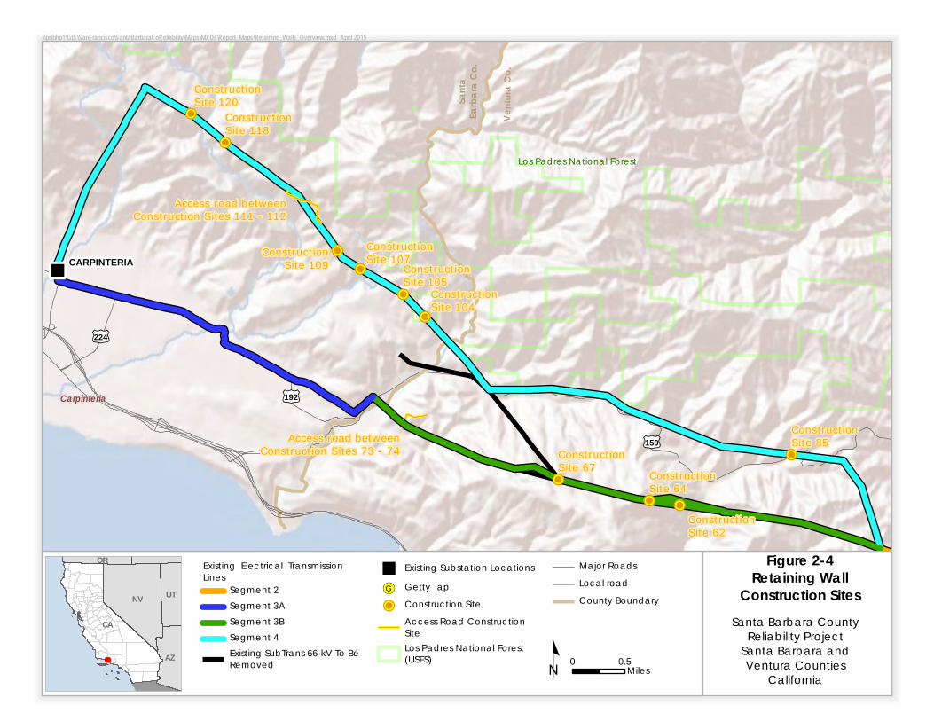
Ifnecessary,additionalhelicopterstagingyardsofapproximately0.5acresinsizewouldbesitedat1locationsthatoptimizeflighttimetostructurelocations.Finalsitingofhelicopterstagingyards,if2suchyardsarerequired,wouldbeidentifiedwiththeinputofthesubtransmissionlinecontractor,3landmanagementagencies,privatelandowners,andthehelicoptercontractorasnecessary.4ApprovalforuseofadditionalstagingyardswouldneedtobeobtainedfromtheCPUCthroughthe5minorprojectrefinementprocessdetailedinSection9.1,“MinorProjectRefinement.”672.3.1.2 Grading 89Gradingactivitieswouldberequiredonlyforproposedconstructionactivities,includingamong10others,theroadworkandpreparationofsubtransmissionwirepullingsites,cranepads,andaccess11roads.Thereisnogradingassociatedwiththeproposedsubstationupgrades.12132.3.1.3 Retaining Walls 1415Retainingwallswouldbeinstalledtoavoidextensivegradingandminimizetheareaofsurface16disturbance.Theapplicanthasidentified2631locationsalongtheprojectroutewhereretaining17wallswouldbeused.Table2‐5liststheconstructionsiteswhereretainingwallswouldbeinstalled18andthetypeofstructuretobeinstalled.Figure2‐4showsthelocationoftheseconstructionsites.1920Table 2‐5 Proposed Locations for Retaining Walls
Construction Site Retaining Wall‐Type
Structure Construction Site Retaining Wall‐Type
Structure 62 SoldierPile 104 MSE64 MSE 105 MSE64 SoldierPile 107 MSE67 MSE 109 MSE74 MSE 118 MSE76 MSE 120 MSE76 GabionSoldierPile 125 MSE85 MSE Accessroadbetween
ConstructionSites73‐74MSE
86 MSE AccessroadbetweenConstructionSites87‐88
MSE
90 MSE AccessroadbetweenConstructionSites89‐90
MSE
93 MSE AccessroadbetweenConstructionSites111‐112
MSEorSoldierPile
96 MSE AccessroadbetweenConstructionSites115‐116
MSE
97 SoldierPile AccessroadbetweenConstructionSites116‐117
MSE
98 MSE AccessroadbetweenConstructionSites125‐126
MSE
99 MSE AccessroadbetweenConstructionSites131‐133
MSE
100 MSE Key:MSE mechanicallystabilizedembankment21
22

SANTA BARBARA COUNTY RELIABILITY PROJECT
2.0 PROJECT DESCRIPTION
MAY 2015 2‐24 FINAL EIR
Table 2‐5 Proposed Locations for Retaining Walls 1
Source:SCEdocumentationsubmitted2012‐20142Key:3MSE mechanicallystabilizedembankment452.3.2 66‐kV Subtransmission Lines and Getty Tap 6 72.3.2.1 Access and Spur Roads 89Approximately120milesofexistingaccessandspurroadswouldbeemployedforconstructionof10theproposedproject.Atpresent,approximately25milesoftheseexistingroadsareprojectedto11requirerestorationwork,includingre‐gradingandrepairoftheexistingroadbed.Theseroads12wouldbeclearedofvegetation;blade‐gradedtoremovepotholes,ruts,andothersurface13irregularities;andre‐compactedtoprovideasmoothanddenseridingsurfacecapableof14supportingheavyconstructionequipment.1516Atpresent,theapplicantprojectsthatapproximatelyfiveofthe120milesofexistingaccessand17spurroadswouldrequireextensiverehabilitation,suchas:1819
Wideningoftheexistingroadbedatcurvesandotherlocations.20
Installationofnew,orrepairofexisting,drainagestructuressuchaswaterbars,overside21drainsandpipeculvertstoallowforconstructiontrafficusage,aswellastopreventroad22damageduetouncontrolledwaterflow.23
Repairandstabilizationofslides,washouts,andotherslopefailuresminimizesurface24disturbancebyinstallingretainingwallsorothermeansnecessarytopreventfuture25failures.Thetypeofstructureusedwouldbebasedonspecificsiteconditions.26
2728
Construction Site Retaining Wall‐Type Structure
Construction Site Retaining Wall‐Type Structure
62 MSE 104 MSE64 MSE 105 MSE64 SoldierPile 107 MSE67 MSE 109 MSE74 MSE 118 MSE76 MSE 120 MSE76 SoldierPile Accessroadbetween
ConstructionSites73‐74MSE
76 Gabion AccessroadbetweenConstructionSites111‐112
MSE
85 MSE
\\prtbhp1\GIS\SanFrancisco\SantaBarbaraCoReliability\Maps\MXDs\Report_Maps\Retaining_Walls_Overview.mxd April 2015
!
!P!P
!P
!P
!P
!P
!P
!P
!P
!P
Access road betweenConstruction Sites 111 - 112
Access road betweenConstruction Sites 73 - 74
Santa
Barb
ara C
o.
Ventu
ra Co
.ConstructionSite 62
ConstructionSite 64
ConstructionSite 67
ConstructionSite 85
ConstructionSite 109
ConstructionSite 107Construction
Site 105ConstructionSite 104
ConstructionSite 118
ConstructionSite 120
Los Padres National Forest
£¤150
£¤224
£¤192Carpinteria
CARPINTERIA
Figure 2-4Retaining Wall
Construction SitesSanta Barbara County
Reliability ProjectSanta Barbara andVentura Counties
Californiaº 0 0.5MilesAZ
CA
NV
OR
UT
Existing Electrical TransmissionLines
Segment 2Segment 3ASegment 3BSegment 4Existing SubTrans 66-kV To BeRemoved
! Existing Substation Locations
!(G Getty Tap!P Construction Site
Access Road ConstructionSiteLos Padres National Forest(USFS)
Major RoadsLocal roadCounty Boundary

SANTA BARBARA COUNTY RELIABILITY PROJECT
2.0 PROJECT DESCRIPTION
MAY 2015 2‐26 FINAL EIR
Inaddition,theproposedprojectwouldrequiretheconstructionofapproximately4milesofnew1spurroads.Constructionactivitiesforthesenewspurroadswouldbesimilartothoseassociated2withtherehabilitationofexistingroads.Accessandspurroadswouldhaveaminimumdrivable3widthof14feet(18feetwidetotal,includinga2‐footshoulderoneachsideoftheroad)butmaybe4widerdependingonfinalengineeringrequirementsandfieldconditions.Generally,thegradeof5accessandspurroadswouldnotexceed12percent;however,incertaincasesgradescouldexceed612percentinordertominimizegradinginareaswithexistingsteepterrainandroadgrades,but7wouldstillcomplywithallapplicableagencyrequirements.reachapproximately14percent.For8gradesexceeding12percent,thesewouldnotexceed40feetinlengthandwouldbelocatedmore9than50feetfromanyotherexcessivegradeoranycurve.AllTypically,curveswouldhavearadius10ofcurvaturenotlessthan50feet,measuredalongthecenterlineoftheusableroadsurface.1112Allspurroadsmorethan500feetlongwouldincludeaY‐typeorcircle‐typeturnaround.Wherea13circle‐typeturnaroundisnotpractical,theapplicantwouldconstructanalternativeturnaround14configurationtoprovidevehicleaccesstothestructurelocation.Thispermanentareawouldalsobe15usedasacranepadforbothconstructionandongoingoperationandmaintenanceactivities.16Approximately70turnaroundswouldbeconstructedorreestablished.1718Allaccessandspurroadswouldbeleftinplacetofacilitatefutureaccessforoperationsand19maintenancepurposes.2021ACattrailwouldbecreatedtoaccessconstructionsite128.Acattrailisarudimentary,temporary22meansofoverlandaccesstypicallydevelopedbyabulldozer.Ingeneral,cattrailsareusedwhere23theterrainistoosteepforconventionalconstructionequipmenttosafelynavigatetotheworksite.24Thecattrailwouldnotbecompactedlikeanaccessroad,andsomevegetationwouldlikelyremain25onthecattrail.Followingconstruction,thecattrailwouldeitherberevegetatedorleftto26revegetatenaturally.27282.3.2.2 Structure Site Preparation 2930Structurepadlocationsandlaydown/workareaswouldfirstbegradedand/orclearedof31vegetationasrequiredtoprovideareasonablylevelandvegetation‐freesurface.Siteswouldbe32gradedsuchthatwaterwouldruntowardthedirectionofthenaturaldrainage.3334Inaddition,drainagewouldbedesignedtopreventpondinganderosivewaterflowsthatcould35causedamagetothestructurefootings.Thegradedareawouldbecompactedtoatleast90percent36relativedensityandwouldbecapableofsupportingheavyvehicles.3738Alaydown/workareawouldbeestablishedadjacenttoeachpoleinstallationlocation.This39laydown/workareawouldbeusedforthetemporarystagingandassemblyofthepole.Inaddition,40withinthelaydown/workarea,acranepadofapproximately40by40feetcouldbeestablished.41Whereexistingterrainwithinthelaydown/workareaissufficienttosupportcraneoperations,the42cranepadwouldbedevelopedwithinthelaydown/workarea,adjacenttothepoleinstallation43location.Inareaswheretheexistingterrainwithinthelaydown/workareaisinsufficienttosupport44craneoperations,aseparatecranepadmaybeclearedofvegetationand/orgradedasnecessaryto45provideanappropriateandlevelsurfaceforcraneoperation.4647Insomesteepand/orruggedterrain,benchingmayberequiredinordertoprovideaccessfor48footingconstruction,assembly,erection,andwirestringingactivitiesduringlineconstruction.49

SANTA BARBARA COUNTY RELIABILITY PROJECT
2.0 PROJECT DESCRIPTION
MAY 2015 2‐27 FINAL EIR
Benchingisatechniqueinwhichanearth‐movingvehicleexcavatesaterracedaccesstostructure1locations.StructurefoundationsforeachTSPwouldrequireasingledrilled,poured‐in‐place2concretefooting.Thefoundationprocessbeginswiththedrillingofafoundationhole.Theholes3wouldbedrilledusingtruck‐ortrack‐mountedexcavatorswithvariousdiameteraugerstomatch4thediameterrequirementsofthestructuretype.TSPswouldrequireanexcavatedhole5approximately5to9feetindiameterandapproximately15to70feetdeep.TSPfootingswould6projectapproximately2to4feetabovegroundlevel.Actualfootingdiametersanddepthsforeach7ofthestructurefoundationswoulddependonthesoilconditionsandtopographyateachsiteand8wouldbedeterminedduringfinalengineering.910Theexcavatedmaterialwouldbedistributedateachstructuresite,usedtobackfillexcavations11fromtheremovalofnearbystructures(ifany),orusedintherehabilitationofexistingaccessroads.12Alternatively,theexcavatedsoilmaybeprovidedtothepropertyowner,uponrequest,ordisposed13ofatanoff‐sitedisposalorrecyclingfacilityinaccordancewithallapplicablelaws.1415Followingexcavationofthefoundationfootings,steelreinforcedrebarcageswouldbeset,survey16positioningwouldbeverified,andconcretewouldthenbeplaced.Steelreinforcedrebarcagesmay17beassembledatstagingyardsanddeliveredtoeachstructurelocationbyflatbedtruckor18assembledatthejobsite.Dependinguponthetypeofstructurebeingconstructed,soilconditions,19andtopographyateachsite,TSPswouldrequireapproximately11to175cubicyardsofconcrete20deliveredtoeachstructurelocation.2122Theuseofwater,fluidstabilizers,drillingmud,and/orcasingswouldbemadeavailabletocontrol23groundcavingandtostabilizethesidewallsfromsloughing.Iffluidstabilizerswereused,mud24slurrywouldbeaddedinconjunctionwiththedrilling.Theconcreteforthefoundationwouldthen25bepumpedtothebottomofthehole,displacingthemudslurry.Mudslurrybroughttothesurfaceis26typicallycollectedinapitortankadjacenttothefoundationand/orvacuumeddirectlyintoatruck27tobereusedordiscardedatanoff‐sitedisposalfacility,inaccordancewithallapplicablelaws.2829Concretesampleswouldbedrawnatthetimeofpourandtestedtoensurethatengineered30strengthswereachieved.Aconcretemixofthetypenormallyusedinthistypeofprojecttakes31approximately20daystocuretoanengineeredstrength.Thisstrengthisverifiedbycontrolled32testingofsampledconcrete.Oncethisstrengthhasbeenachieved,crewsfortheproposedproject33wouldbepermittedtocommenceerectionofthestructure.3435Conventionalconstructiontechniquesasdescribedabovewouldgenerallybeusedforinstalling36newfoundations.Alternativefoundationinstallationmethodsmaybeusedwhereconventional37methodsarenotpractical.Incertaincases,equipmentandmaterialmaybedepositedatstructure38sitesusinghelicoptersorbyworkersonfoot,andcrewsmaypreparethefoundationsusinghand39laborassistedbyhydraulicorpneumaticequipment,orothermethods.4041Duringconstruction,existingconcretesupplyfacilitieswouldbeusedwherefeasible.Foranyareas42thatdonothaveconcretesupplyfacilities,atemporaryconcretebatchplantwouldbesetupinan43establishedmaterialstagingyard.Equipmentforthisplantwouldincludeacentralmixerunit44(drumtype);threesilosforinjectingconcreteadditives,flyash,andcement;awatertank;portable45pumps;apneumaticinjector;andaloaderforhandlingconcreteadditivesnotinthesilos.Dust46emissionswouldbecontrolledbywateringtheareaandbysealingthesilosandtransferringthe47fineparticulatespneumaticallybetweenthesilosandthemixers.4849

SANTA BARBARA COUNTY RELIABILITY PROJECT
2.0 PROJECT DESCRIPTION
MAY 2015 2‐28 FINAL EIR
Priortodrillingforfoundations,theapplicantoritscontractorwouldcontactUnderground1ServiceAlerttoidentifyanyundergroundutilitiesintheconstructionzone.23Tubular Steel Pole 4
TSPsconsistofmultiplesections.Thepolesectionswouldbeplacedintemporarylaydown/work5areasateachpolelocation.Dependingonconditionsatthetimeofconstruction,thetopsections6maycomepre‐configured,beconfiguredontheground,orbeconfiguredafterpoleinstallationwith7thenecessarycrossarms,insulators,andwirestringinghardware.89Acranewouldbeusedtoseteachsteelpolebasesectionontopofthepreviouslyprepared10foundations.IfexistingterrainaroundtheTSPlocationisnotsuitabletosupportcraneactivities,a11temporarycranepadwouldbeconstructedwithinthelaydown/workarea.Eachpolebasesection12wouldbesecuredfirst,andthenthesubsequentsectionoftheTSPwouldbeplacedonthebase13section.Thepolesectionsmayalsobespot‐weldedtogetherforadditionalstability.Dependingon14theterrainandavailableequipment,thepolesectionscouldalsobepre‐assembledintoacomplete15structurepriortosettingtheTSPs.1617Lightweight Steel Pole 18
EachLWSpolewouldrequireaholetobeexcavatedusinganaugerorabackhoe.Excavated19materialwouldbehandledaccordingtotheapplicant’swastemanagementpractices(Section2.4.4).20LWSpolesconsistofseparatebaseandtopsectionsandmaybeplacedintemporarylaydown/work21areasateachpolelocation.Dependingonconditionsatthetimeofconstruction,thetopsections22maycomepre‐configured,beconfiguredontheground,orbeconfiguredafterpoleinstallationwith23thenecessarycrossarms,insulators,andwire‐stringinghardware.TheLWSpoleswouldbe24installedintheholes,typicallybyalinetruckwithanattachedboom.Eachpolebasesectionwould25besecuredfirst,andthenthetopsectionplacedonthebasesection.Dependingontheterrainand26availableequipment,thepolesectionscouldalsobeassembledintoacompletestructureonthe27groundpriortosettingthepolesinplacewithintheholes.2829Lightweight Steel Pole H‐Frame 30
EachLWSpoleforanH‐framestructurewouldrequireaholetobeexcavatedusinganaugerora31backhoe.Excavatedmaterialwouldbehandledaccordingtotheapplicant’swastemanagement32practices(Section2.4.4).LWSH‐framepolesconsistofseparatebaseandtopsectionsandmaybe33placedintemporarylaydown/workareasateachpolelocation.Dependingonconditionsatthe34timeofconstruction,thetopsectionsmaycomepre‐configured,beconfiguredontheground,orbe35configuredafterpoleinstallationwiththenecessarycrossarms,insulators,andwire‐stringing36hardware.TheLWSpoleswouldthenbeinstalledintheholes,typicallybyalinetruckwithan37attachedboom.Thecross‐bracingsusedtoconnectthetwopoleswouldbeinstalledaftererection38ofthestructure.3940
SANTA BARBARA COUNTY RELIABILITY PROJECT
2.0 PROJECT DESCRIPTION
MAY 2015 2‐29 FINAL EIR
J‐Tower 1
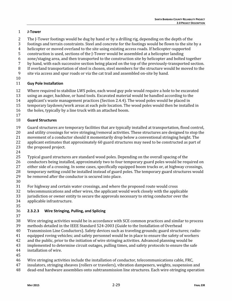
TheJ‐Towerfootingswouldbedugbyhandorbyadrillingrig,dependingonthedepthofthe2footingsandterrainconstraints.Steelandconcreteforthefootingswouldbeflowntothesitebya3helicopterormovedoverlandtothesiteusingexistingaccessroads.Ifhelicopter‐supported4constructionisused,sectionsoftheJ‐Towerwouldbeassembledatahelicopterlanding5zone/stagingarea,andthentransportedtotheconstructionsitebyhelicopterandboltedtogether6byhand,witheachsuccessivesectionbeingplacedonthetopofthepreviously‐transportedsection.7Ifoverlandtransportationofsteelischosen,steelmembersforthestructurewouldbemovedtothe8siteviaaccessandspurroadsorviathecattrailandassembledon‐sitebyhand.9 10Guy Pole Installation 11
WhererequiredtostabilizeLWSpoles,eachwoodguypolewouldrequireaholetobeexcavated12usinganauger,backhoe,orhandtools.Excavatedmaterialwouldbehandledaccordingtothe13applicant’swastemanagementpractices(Section2.4.4).Thewoodpoleswouldbeplacedin14temporarylaydown/workareasateachpolelocation.Thewoodpoleswouldthenbeinstalledin15theholes,typicallybyalinetruckwithanattachedboom.1617Guard Structures 18
Guardstructuresaretemporaryfacilitiesthataretypicallyinstalledattransportation,floodcontrol,19andutilitycrossingsforwirestringing/removalactivities.Thesestructuresaredesignedtostopthe20movementofaconductorshoulditmomentarilydropbelowaconventionalstringingheight.The21applicantestimatesthatapproximately60guardstructuresmayneedtobeconstructedaspartof22theproposedproject.2324Typicalguardstructuresarestandardwoodpoles.Dependingontheoverallspacingofthe25conductorsbeinginstalled,approximatelytwotofourtemporaryguardpoleswouldberequiredon26eithersideofacrossing.Insomecases,specificallyequippedboomtrucksor,athighwaycrossings,27temporarynettingcouldbeinstalledinsteadofguardpoles.Thetemporaryguardstructureswould28beremovedaftertheconductorissecuredintoplace.2930Forhighwayandcertainwatercrossings,andwheretheproposedroutewouldcross31telecommunicationsandotherwires,theapplicantwouldworkcloselywiththeapplicable32jurisdictionorownerentitytosecuretheapprovalsnecessarytostringconductoroverthe33applicableinfrastructure.34352.3.2.3 Wire Stringing, Pulling, and Splicing 3637WirestringingactivitieswouldbeinaccordancewithSCEcommonpracticesandsimilartoprocess38methodsdetailedintheIEEEStandard524‐2003(GuidetotheInstallationofOverhead39TransmissionLineConductors).Safetydevicessuchastravelinggrounds;guardstructures;radio‐40equippedrovingvehicles;andsafetypersonnelwouldbeinplacetoensurethesafetyofworkers41andthepublic,priortotheinitiationofwirestringingactivities.Advancedplanningwouldbe42implementedtodeterminecircuitoutages,pullingtimes,andsafetyprotocolstoensurethesafe43installationofwire.4445Wirestringingactivitiesincludetheinstallationofconductor,telecommunicationscable,FRC,46insulators,stringingsheaves(rollersortravelers),vibrationdampeners,weights,suspensionand47dead‐endhardwareassembliesontosubtransmissionlinestructures.Eachwire‐stringingoperation48

SANTA BARBARA COUNTY RELIABILITY PROJECT
2.0 PROJECT DESCRIPTION
MAY 2015 2‐30 FINAL EIR
wouldincludeawirepullerpositionedatoneendandatensionerandwirereelstandtruck1positionedattheotherendofthelinesegmenttobepulled.23Thefollowingfivestepsdescribetypicalwirestringingactivities:45
1. Planning:Developawirestringingplantodeterminethesequenceofwirepullsandthe6set‐uplocationsforthewirepull/tensioning/splicingequipment.7
2. SockLineThreading:Abuckettruckistypicallyusedtoinstallalightweightsocklinefrom8structuretostructure.Thesocklinewouldbethreadedthroughthewirerollersinorderto9engageacamlockdevicethatwouldsecurethepullingsockintheroller.Thisthreading10processwouldcontinuebetweenallstructuresthroughtherollersoftheparticularsetof11spansselectedforaconductorpull.Inareaswhereabuckettruckisunabletoinstalla12lightweightsockline,ahelicopterwouldflythelightweightsocklinefromstructureto13structure.Thesocklinewouldbethreadedthroughthewirerollersinordertoengagea14camlockdevicethatwouldsecurethepullingsockintheroller.Thisthreadingprocess15wouldcontinuebetweenallstructuresthroughtherollersofaparticularsetofspans16selectedforaconductorpull.17
3. Pulling:Thesocklinewouldbeusedtopullintheconductorpullingropeand/orcable.The18pullingropeorcablewouldbeattachedtotheconductorusingaspecialswiveljointto19preventdamagetothewireandtoallowthewiretorotatefreelytopreventcomplications20fromtwistingastheconductorunwindsoffthereel.21
4. Splicing,Sagging,andDead‐Ending:Oncetheconductorispulledin,ifnecessary,allmid‐22spansplicingwouldbeperformed.Oncethesplicinghasbeencompleted,theconductor23wouldbesaggedtopropertensionanddead‐endedtostructures.24
5. Clipping‐In:Aftertheconductorisdead‐ended,theconductorswouldbesecuredtoall25tangentstructures;aprocesscalledclippingin.Wherepossible,theconductorbeing26replacedwouldbeusedtopullinthenewconductor.27
28Thepuller,tensioner,andsplicingset‐uplocationsassociatedwiththeproposedprojectwouldbe29temporaryandthelandthatmaybedisturbedwouldberestoredtoasclosetopreconstruction30conditionsaspossibleortotheconditionsagreeduponbetweenthelandownerandtheapplicant.31Theset‐uplocationsrequirelevelareastoallowformaneuveringoftheequipmentand,when32possible,theselocationswouldbelocatedonexistingroadsandlevelareastominimizetheneedfor33gradingandcleanup.Thenumberandlocationofthesesiteswouldbedeterminedduringfinal34engineering.Theapproximateareaneededforstringingset‐upsassociatedwithwireinstallationis35variableanddependsuponterrain.3637Wirepullsarethelengthbetweentwowireinstallationpointsalongtheline.Wirepullsare38designedbasedonavailabilityofdead‐endstructures,conductorsize,geometryofthelineas39affectedbypointsofinflection,terrain,andsuitabilityofstringingandsplicingequipmentset‐up40locations.Onrelativelystraightalignments,typicalwirepullsoccurapproximatelyevery10,000to4112,000feet.Whenthelineroutealignmentcontainsmultipledeflectionsorissituatedinrugged42terrain,thelengthofthewirepullisdecreased.Generally,pullinglocationsandequipmentset‐ups43wouldbeindirectlinewiththedirectionoftheoverheadconductorsandestablished44approximatelyadistanceofthreetimestheheightawayfromtheadjacentstructure.4546
SANTA BARBARA COUNTY RELIABILITY PROJECT
2.0 PROJECT DESCRIPTION
MAY 2015 2‐31 FINAL EIR
Eachstringingoperationconsistsofapullerset‐uppositionedatoneendandatensionerset‐up1withwirereelstandtruckpositionedattheotherendofthewirepull.Pullingandwiretensioning2locationsmayalsobeusedforsplicingandfieldsnubbingoftheconductors.Fieldsnubs(i.e.,3anchoringanddead‐endhardware)wouldbetemporarilyinstalledtosagconductorwiretothe4correcttensionatlocationswherestringingequipmentcannotbepositionedinbackofadead‐end5structure.672.3.2.4 Insulators and Conductors 89Installation of Marker Balls 10
Aspresentedearlier,allFAArecommendations,includingtheinstallationofmarkerballson11appropriateinfrastructurewherenecessary,wouldbeimplementedintothedesignoftheproposed12project.Inmostcases,markerballswouldbeinstalledbyhelicopterbecauseofthismethod’s13efficiency,minimalgrounddisturbance,andabilitytooperateinruggedterrain.Inlimited14circumstances,markerballsmaybeinstalledusingaspacercart,butthismethodisgenerallyless15efficientandmayresultinadditionalgrounddisturbance.1617Theapplicantwouldselectthemostsuitableinstallationmethodforaparticularspan.The18applicantwouldgenerallyusealight‐dutyhelicoptertoinstallthemarkerballs.Installationby19helicoptermayrequireanoutagethatde‐energizesnearbyenergizedsubtransmissionlinesand20transmissionlines.2122Helicopterinstallationrequiresstagingatalandingzone,wherethehelicopterwouldpickupthe23constructionworkerandamarkerball(s)andtraveltotheinstallationlocation.Tominimize24grounddisturbance,theapplicantwouldusepreviouslydisturbedareasaslandingzones.2526Inlimitedcircumstances,theapplicantmayemployaspacercarttoinstallmarkerballsand27associatedhardware.Thespacercartwouldbeinstalledontheoverheadwirebyinstallationcrews,28eitherbyhelicopterorbyusingacraneplacedonanexistingcranepadcreatedduringthe29constructionofthestructure.Becauseanyinstallationofspacercartsbycranewouldtakeplace30duringconstruction,itisnotexpectedthatinstallationoruseofspacercartswouldcauseany31additionalgrounddisturbance.3233Duetotheterrainintheareaswheremarkerballsmayberequired,installationbycranewould34likelybeinfeasibleandmayentailsignificantadditionalgrounddisturbance.Forthesereasons,35craneinstallationofmarkerballswouldnotbeconsideredfortheproposedproject.3637Fault Return Conductor 38
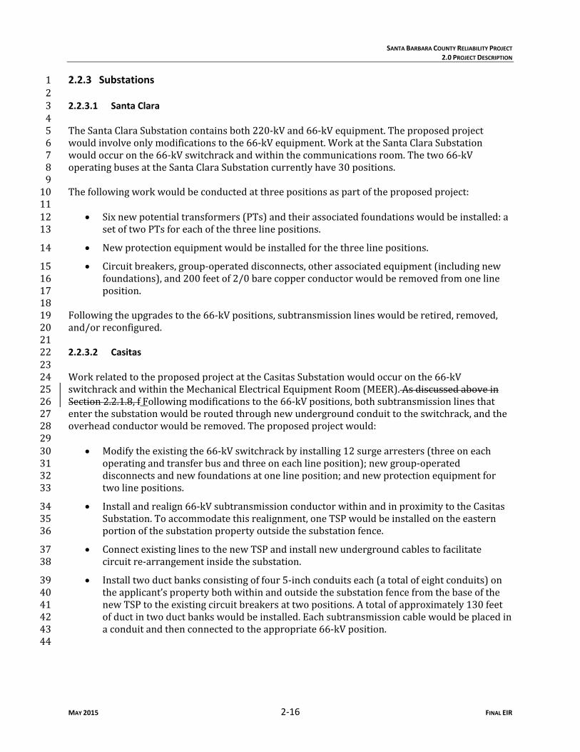
TheFRCwouldbeinstalledalong2.3milesofSegment3A.Thisconductorwouldbeinstalled39parallelwiththeexistingoverhead66‐kVsubtransmissionlinerelocationproposedalongSegment403A,about1to2feetabovetheexistingthird‐partytelecommunicationfacilities,and4to6feet41belowtheexisting16‐kVdistributionline(Figure2‐5).TheapplicantanticipatesinstallingtheFRC42withinthesametimeframeastheproposedoverheadtelecommunicationline.Tomaintainproper43clearances,theexistingtelecommunicationanddistributionfacilitiesthatwouldberelocatedto44existingLWSpolesmayneedtoberearranged.4546
47

1003948.0001.06.a.ai (2015 CORP Archive) 05/14/2015
Photo source: Regulatory A�airs - Energy & Environmental Policy Southern California Edison
Figure 2-5
Example Fault Return Conductor
66-kV
4/0 FRC
Telecom
This example 66-kV LWS steel pole line does not have a 16-kV line co-located on it; however, for purposes of understanding where such a line would be for comparison relating to S e g m e n t 3 A o f S B C R P, t h i s ye l l ow l i n e represents the location on the poles where a typical 16-kV line would be co-located.

SANTA BARBARA COUNTY RELIABILITY PROJECT
2.0 PROJECT DESCRIPTION
MAY 2015 2‐33 FINAL EIR
12.3.2.5 Underground Facilities 23Theproposedprojectwouldrequireatotalof130feetofnewunderground66‐kVsubtransmission4lineandassociatedtransitionandsupportstructuresattheCasitasSubstation.Installingthe5undergroundsubtransmissioncablewouldrequiresurveying,trenching,ductbankinstallation,6pullingandsplicingofthecable,andconstructionoftransitionstructures.Theseactivitiesare7describedbelow.89Surveying 10
Theapplicantwouldconductasurveyofexistingundergroundutilitiesalongtheproposed11undergroundsubtransmissionductbankroute.Theapplicantwouldnotifyallapplicableutilities12throughtheUndergroundServiceAlertserviceinordertolocateandmarkexistingutilities.In13addition,whennecessary,theapplicantwouldconductexploratoryexcavationstoverifythe14locationofexistingutilities.15 16
Trenching 17
Anapproximately20‐to24‐inch‐widetrenchvaryingindepthfromapproximately5feetto12feet18wouldberequiredtoinstalltheproposed66‐kVundergroundsubtransmissionline.4During19trenching,theapplicantwouldmarkthelocationandapplicableundergroundutilities,layouta20trenchline,saworcutasphaltorconcretepavementasnecessaryalongthetrenchline,digtothe21appropriatedepthwithabackhoeorsimilarequipment,andinstalltheductbank.Oncetheduct22bankhasbeeninstalled,thetrenchwouldbebackfilledwithsandslurrymix.Theapplicantwould23disposeofexcavatedmaterialsatanoff‐sitedisposalfacilityinaccordancewithapplicable24regulations.Similarly,shouldgroundwaterbeencountered,theapplicantwouldpumpitintoatank25andtransportittoanoff‐sitedisposalfacilitypursuantapplicableregulations.Steelplateswouldbe26placedoveropentrenchsectionstomaintainvehicularandpedestriantraffic.Provisionsfor27emergencyvehicleaccesswouldbearrangedwithlocaljurisdictionsinadvanceofconstruction28activities.2930Duct Bank Installation 31
Theproposedductbankwouldcomprisecableconduit,spacers,groundwire,andconcrete32encasement.Theductbankwouldconsistoftwosetsoffour5‐inchdiameterpolyvinylchloride33(PVC)conduitsfullyencasedwithaminimumof3inchesofconcrete.Themajorityoftheproposed3466‐kVundergroundsubtransmissionductbankswouldbeinstalledinaverticallystacked35configuration,andeachductbankwouldbeapproximately21inchesinheightby20inchesin36width.Inareaswhereundergroundutilitiesarehighlycongestedorwhereitisnecessarytofanout37theconduitstoreachterminationstructures,theapplicantmayberequiredtouseaflat38configurationductbank.Intheeventthattheproposed66‐kVsubtransmissionductbankwould39crossorrunparalleltootherundergroundutilitiesstructuresthatoperateatnormalsoil40temperature(gas,telephone,watermains,stormdrains,sewerlines),aminimalradialclearanceof416inchesforcrossingand12inchesforparallelingthesestructureswouldberequired.Clearances42anddepthsusedbytheapplicantwouldcomplywithRule41.4ofCaliforniaPublicUtilities43Commission(CPUC)GeneralOrder(GO)128.444 TheapplicantwouldadjusttrenchdimensionstomeettheCaliforniaOccupationalandSafetyHealthAdministrationrequirements.Variationsintrenchdepthareduetothechangeinelevationbetweenthedrivewayandsubstationyard.

SANTA BARBARA COUNTY RELIABILITY PROJECT
2.0 PROJECT DESCRIPTION
MAY 2015 2‐34 FINAL EIR
1Cable Pulling, Splicing, Termination 2
Followingtheductbankinstallation,theapplicantwouldpulltheelectricalcablesthroughtheduct3bankbyusingacablereelandapullingreellocatedattheoppositeend.Further,theapplicant4wouldterminatecablesattransitionstructures,whichwouldplacecablesfromundergroundto5overheadconfiguration.67Transition Structures 8
TheapplicantwouldinstallaTSPriserpoletotransitioncablesfromundergroundtoanoverhead9configuration.Thistransitionstructurewouldsupportcableterminations,lightningarresters,and10dead‐endhardwareforoverheadconductors.Constructionmethodsforthisstructurearedescribed11inSection2.3.2.2.Ontheoppositesideoftheductbank,cableswouldtransitionthroughconduit12sweepsandconnecttotheexisting66‐kVswitchrackpositionswithintheCasitasSubstation.13142.3.2.6 Transfer and Removal of Existing Structures/Facilities 1516Theproposedprojectwouldinvolveremovingstructures,conductor,andassociatedhardware.17Table2‐6summarizesthenumberofstructuresandprojectcomponentsproposedtoberemoved.18Thecomponentswouldberemovedbyusinghelicoptersinareasofdifficultaccess(particularly19alongSegment4),orbyequipmentandvehiclesinareasaccessiblebyground.202122Table 2‐6 Summary of Structures and Conductor Proposed To Be Removed
Project Component Structures Structure
Foundations1 Conductor Type/Length
Segment1 0 15 N/ASegment2 0 15 N/ASegment3A 17woodpoles 0 N/ASegment3B 31LSTs 31 2/0barecopper/30,000feetSegment4 74LSTs;
7woodpoles;1woodH‐frame
74 2/0barecopper/36,740feet653ACSR/47,600feet
Segment5 12LSTs2woodH‐frames
12 2/0barecopper/10,776feet
GettyTap 4woodH‐frames;3woodpoles
0 2/0barecopper/200feet653ACSR/75feet
CarpinteriaSubstation 3LSTs;2woodpoles;3switches
3 653ACSR/1,070feet
CasitasSubstation 0 0 2/0barecopper/180feet336ACSR/74feet
Source:SCEdocumentationsubmitted2012‐2014Source:SCE2012Note:1Maximumnumberofstructureremovals.Key:ACSR Aluminumconductorsteel‐reinforcedLST LatticesteeltowerN/A Notapplicable

SANTA BARBARA COUNTY RELIABILITY PROJECT
2.0 PROJECT DESCRIPTION
MAY 2015 2‐35 FINAL EIR
1Forareasaccessibleontheground,thetransferandremovalofexistingstructuresandfacilities2wouldinvolvethefollowingsequenceofactivities:3 4
Wirepullinglocations:Wirepullingsiteswouldtypicallybelocatedapproximatelyevery510,000to12,000feetalongtheexisting66‐kVsubtransmissionlines.Pullingsitescould6occuratmorefrequentintervalsdependingonthelocationsofdead‐endstructuresand7turningpoints.Pullandtensioningequipmentwouldbesitedatthewirepullingsitesto8facilitateremovaloftheexistingconductors.9
Conductorremoval:Afterthewirepullingequipmentisinplace,theoldconductoris10typicallytransferredtothenewstructuresthatwouldbepre‐riggedwithrollers.Theold11conductorwouldthenbepulledoutwithapullingropeand/orcableattachedtothetrailing12endoftheconductor,whichwouldbeusedtopullinthenewconductor.Theoldconductor13wirewouldbetransportedtoaconstructionyard,whereitwouldbepreparedforrecycling.14
Structureremoval:Foreachstructuretoberemoved,anapproximately100‐by150‐foot15workareawouldtypicallyberequired.Moststructureremovalactivitieswouldusethe16cranepadorotherpreviouslydisturbedareasestablishedforstructureinstallation.If17previouslydisturbedareasadjacenttothestructurearenotavailable,anareawouldbe18clearedofvegetationandgradedifnecessary.Thecranewouldtypicallybepositioned19approximately60feetfromthetowerlocationtodismantlethetowerstructure.Structures20wouldbedismantleddowntothefoundationsandthematerialswouldbetransportedtoa21stagingyard,wheretheywouldbepreparedforrecycling.Inareasnotsuitedforcrane22access,towersmaybedisassembledbyhand.23
Footing/foundationremoval:Footingswouldberemovedtoapoint1to2feetbelowgrade,24exceptinplaceswhereremovalcouldresultinerosionproblemsorlandownerconcerns,25andtheholeswouldbefilledwithexcesssoilandsmoothedtomatchthesurrounding26grade.Footingmaterialswouldbetransportedtoastagingyard,wheretheywouldbe27preparedfordisposal.28
29Priortoremovalofexistingstructures,subtransmissionlineswouldbetransferredtonew30structures.Approximately17woodpolesthatareadjacenttopreviouslyinstalledLWSpolesin31Segment3Awouldberemovedaspartoftheproposedproject.Sixofthese17polescurrentlyhave32distributionfacilities.Priortoremovalofexistingpoles,theexistingdistributionlinesand33associatedhardwarewouldbetransferredtotheLWSpoles.Allremainingdistributionequipment34thatisnotreusedbytheapplicantwouldberemovedanddeliveredtoafacilityforrecycling.35Typicaldistributiontransferwouldincludetheuseoftwobuckettrucks.3637Aseparategroupoffiveofthese17existingwoodpolescurrentlyhaveonlythird‐party38telecommunicationfacilities.Thethird‐partyequipmentwouldbetransferredbyitsownerorby39theapplicanttothesubtransmissionpolesinSegment3Aaspartoftheproposedproject,orthe40applicantwouldrelinquishthesepolestothethirdparty.4142Fourofthe17existingwoodpoleshavenoequipmentinstalledonthem.Thesepoleswouldbe43removedbytheapplicantaspartoftheproposedproject.4445Woodpolesnotrelinquishedtoathird‐partyjointutilityownerwouldbecompletelyremovedonce46thesubtransmission,distribution,andtelecommunicationlinesaretransferredtonewpoles.This47processwouldremovetheentirepole,includingabove‐andbelow‐gradeportions.Theholesleft48

SANTA BARBARA COUNTY RELIABILITY PROJECT
2.0 PROJECT DESCRIPTION
MAY 2015 2‐36 FINAL EIR
fromremovingthepoleswouldbebackfilledwithspoilsthatmaybeavailableasaresultofthe1excavationfornewpolesandimportedfillasneeded.Nonon‐relinquishedexistingwoodpoles2wouldbetoppedandleftinplace.Typicalpoleremovalwouldincludetheuseofaboomtruck,as3wellasonecompaniontruck,tosupportthestructureduringdismantlingandremovalofthepole.4Backfilledholeswouldbecompactedandsmoothedtomatchthesurroundinggrade.56Dependingontheirtype,condition,andoriginalchemicaltreatment,removedwoodpolescouldbe7reusedbytheapplicantforotherpurposes,disposedofinaClassIhazardouswastelandfill,or8disposedofinthelinedportionofaRegionalWaterQualityControlBoard(RWQCB)certified9municipallandfill.10112.3.2.7 Energizing Subtransmission Lines 1213Energizingthenewlinesisthefinalstepincompletingthesubtransmissionconstruction.Toreduce14theneedforelectricserviceinterruption,de‐energizingandre‐energizingtheexistinglinesmay15occuratnightwhenelectricaldemandislow.OnlytheGettySubstationanditssinglecustomer16wouldexperienceashort‐durationserviceoutageasnewlinesareenergized.17182.3.2.8 Helicopter Use 1920Helicopterswouldbeusedtosupportconstructionactivitiesinareaswhereaccessislimited(e.g.,21nosuitableaccessroad,limitedconstructionareatofacilitateon‐sitestructureassembly,and/or22environmentalconstraintstoaccessingprojectcomponentswithstandardconstructionvehicles23andequipment)orwheresystemoutageconstraintsareafactor.Project‐relatedhelicopter24activitiescouldincludetransportationofconstructionworkers,deliveryofequipmentand25materialstostructuresites,structureplacement,hardwareinstallation,conductorand26telecommunicationscablestringingoperations,andinstallationofmarkerballs.Helicoptersmaybe27usedinotherareastofacilitateconstruction,dependingonrecommendationsmadebythe28installationcontractor.2930Helicopteroperationswouldoccurinareasnecessarytosupporttheconstructionandoperationof31theproposedproject.Helicoptersandtheirassociatedsupportvehiclesandequipmentmaybe32basedatalocalairportatnightoronoffdays.Associatedground‐basedsupportvehicleswould33utilizeexisting,rehabilitated,ornewaccessorspurroads.3435SCEhasidentified15preliminaryhelicopterlandinglocations.Thelocationsareonacombination36ofpreviouslydisturbedexistingaccessand/orspurroadsandundisturbedareasadjacenttothe37roads.Theundisturbedareasmayrequirebrushing.Thelandingzoneswouldvaryinsizeandare38estimatedtobeaminimumof2,500squarefeetandpotentiallyuptoapproximately8,500square39feet,dependingonwhetherthesamelocationisusedforotherprojectconstructionactivity.These40landingzoneswouldsupportconstruction,potentialhelicopterrefueling,andemergencylandings;41however,theproposedlandingzonesarepreliminaryandmaybemovedand/ormodifiedduring42finalengineering.43442.3.3 Substations 4546Somebelow‐gradeconstructionforinstallationofsubstationequipment,subtransmission47conductorandtelecommunicationscablewouldoccuratCarpinteria,Casitas,andSantaClara48
SANTA BARBARA COUNTY RELIABILITY PROJECT
2.0 PROJECT DESCRIPTION
MAY 2015 2‐37 FINAL EIR
substations.Thesefacilitiesmayincludecabletrenches,conduits,equipmentfoundationsand/or1ductbanks.23Above‐gradeinstallationofsubstationfacilities,suchasdisconnectswitches,potential4transformers,andcircuitbreakers,wouldbecompletedattheCarpinteriaSubstation,Casitas5Substation,andSantaClaraSubstation.AttheCarpinteriaSubstation,a66‐kVbustiepositionwould6alsobeinstalled.Thesefacilitieswouldlikelybeinstalledonnewstructures.782.3.4 Telecommunications 9 102.3.4.1 Equipment Installation 1112Newterminalequipment,channelmultiplexerequipment,andothertelecommunicationequipment13deviceswouldbeinstalledonequipmentrackslocatedwithintheCasitasSubstationMEER,14CarpinteriaSubstationMEER,GoletaSubstationcommunicationsroom,OrtegaSubstationMEER,15SantaBarbaraSubstationMEER,SantaClaraSubstationcommunicationsroom,andVentura16SubstationMEER.Thenewtelecommunicationequipmentinstallationandtheattachmentofthe17proposednewtelecommunicationcablewouldallowtheconfigurationofnewopticalcable18lightwavesystemsconnectingtheabovelocations.Telecommunicationcircuitsforlineprotection,19SCADA,communication,control,andmonitoringwouldbeconfiguredandwiredtotheappropriate20transmission/substationrelaysorequipment.21222.3.4.2 Cable Installation 2324TelecommunicationscablewouldbeinstalledatornearthetopofoverheadstructuresinSegments251,2,and4.Pullingandsplicinglocationswouldbethesameasthoseusedforinstallationof26subtransmissionconductor.Telecommunicationcablespliceswouldbemadewithin36‐by36‐by2710‐inchmetalenclosuresthatwouldbeattachedtosubtransmissionstructureswithmetalstraps.28AlongSegments1,2,and4,spliceboxeswouldbeinstalledonsubtransmissionstructuresat29locationsnomorethan2miles20,000feetapart.3031AttheSantaClaraSubstation,CasitasSubstation,andCarpinteriaSubstation,the32telecommunicationscablewouldtransitionfromanoverheadconfigurationtoanunderground33configurationthroughrisersinstalledonTSPsandbyusingmetalbandingtoattachthecabletothe34legsofanLST.RiserswouldbeinstalledonaTSPattheCarpinteriaSubstationandonthe35easternmostTSPinSegment1adjacenttotheSantaClaraSubstation.3637NewundergroundfacilitieswouldbeinstalledattheCasitasSubstation,CarpinteriaSubstation,and38SantaClaraSubstation.Conduitwouldbeinstalledintrenchesapproximately11incheswideand3639inchesdeep.Newundergroundconduitandstructureswouldtypicallybeinstalledwithabackhoe.40PVCconduitwouldbeplacedinthetrenchandcoveredwithaminimumofapproximately3inches41ofconcreteslurry,thenbackfilledandcompacted.4243Thetelecommunicationscablewouldbeinstalledinaninnerductthatprotectsandidentifiesthe44cablewithintheundergroundconduitandstructures.Toinstalltheinnerduct,itwouldfirstbe45pulledintheconduitfromstructuretostructureusingapullropeandpullingmachineortruck‐46mountedhydrauliccapstan.Thenthetelecommunicationscablewouldbepulledinsidethe47innerductusingthesameprocedure.4849

SANTA BARBARA COUNTY RELIABILITY PROJECT
2.0 PROJECT DESCRIPTION
MAY 2015 2‐38 FINAL EIR
2.3.5 Removal/Replacement/Relocation of Irrigation Infrastructure of Additional Structures 1 2Portionsoftheproposedprojectwouldbeconstructedonirrigatedagriculturallands.These3propertiescontainirrigationinfrastructure,includingpumps,sprinklers,supplylines,andother4equipment,thatwouldneedtoberemoved,relocated,and/orreplacedtofacilitateconstructionof5theproposedproject.Priortoconstruction,theapplicantwouldconsultwithpropertyownersto6locateirrigationinfrastructureanddetermineappropriateprotectionmeasures.Actionscould7includethemarkingofagriculturalinfrastructure,installationofsteelorwoodplatingonaccess8roadstodistributetheweightofconstructionvehiclesandprotectshallow‐buriedirrigationpiping,9ortheinstallationoftemporaryprotectionstructures(bollards,jerseywalls)adjacentto10infrastructurealongaccessroads.Whereinfrastructurecannotbeprotectedinplace,theapplicant11wouldtemporarilyrelocateinfrastructuretopreventdamageandwouldthenre‐sitethe12infrastructurefollowingcompletionofconstruction.Infrastructuredamagedduringconstructionor13relocationwouldberepairedorreplacedasclosetopreconstructionconditionsasfeasibleortothe14conditionsagreeduponbetweenthelandownerandtheapplicantfollowingthecompletionof15constructionoftheproposedproject.16172.3.6 Post Construction Activities 1819Followingthecompletionofconstructionfortheproposedproject,theapplicantwouldcleanupall20temporarilydisturbedareas(whichmayincludethematerialstagingareas,constructionsetup21areas,pullandtensionsites,andsplicingsites)asclosetopre‐constructionconditionsasfeasible,22ortotheconditionsagreeduponbetweenthelandownerandtheapplicant.23242.3.7 Land Disturbance and Acquisition 2526Constructionoftheproposedprojectwouldresultinthedisturbanceofapproximately313.5acres27oflandattheproposedprojectcomponents.Theapplicantestimatesthatapproximately112acres28wouldbedisturbedpermanently.Theapproximatelanddisturbancefromimplementationofthe29proposedprojectissummarizedinTable2‐7.Theapplicantwouldacquiretemporaryconstruction30easementswherenecessary,particularlyforpullingsitesandstagingareas/laydown/workyards.3132ExceptfortwoportionsalongSegment3B(totaling6,300feet)thatwouldoccurinnewROW,the33proposedprojectinfrastructurewouldbebuiltwithinexistingfee‐ownedoreasementROWalready34operatedandmaintainedbytheapplicant.Inaddition,aminorshifttothenortheast,primarily35affectingtheoverhangofthenewconductorsofthe66kVsubtransmissionlinealignment,maybe36requiredforanapproximate3,700‐footportionofSegment3Binordertoaddressageotechnical37concern.Similarly,existingandproposedaccessroadsandspurroadsproposedbytheapplicant38wouldbelocatedprimarilywithinexistingROWsorcoveredundereasements.Thewidthofthese39ROWsvariesoverthelengthoftheproposedprojectfrom24to165feet.Exceptfornewlandrights40necessarytoaccommodatethisshortrealignmentwithinSegment3B,theapplicantdoesnot41anticipateacquisitionofadditionalorupgradedrightsonprivatelands.424344
45

SANTA BARBARA COUNTY RELIABILITY PROJECT
2.0 PROJECT DESCRIPTION
MAY 2015 2‐39 FINAL EIR
1Table 2‐7 Approximate 7 Approximate Land Disturbance from Implementation of the
Proposed Project
Component Sites/Miles
Temporary Disturbance
(acres)
Permanent Disturbance
(acres) Total Disturbance
(acres) MaterialStagingYards1 4sites 15.0 0 15.0
NewAccess/SpurRoads 4miles 0 12.0 12.0MinorRehabilitationofExistingAccess/SpurRoads
25miles 0 76.0 76.0
ExtensiveRehabilitationofExistingAccess/SpurRoads
5miles 31.0 15.0 46.0
LWSPole 5sites 1.5 0.5 2.0GuyPole 10sites 2.5 0.5 3.0LWSH‐Frame 4sites 1.0 0.5 1.5TSP 86sites 52.0 7.0 59.0J‐Towers 4sites 1.5 0.52 2.03
PullandTensioningSite 13sites 15.0 0 15.0Tower/H‐FrameRemovalSites 127sites 65.5 0 65.5LSTFootingOnlyRemovalSites 30sites 4.0 0 4.0WoodPoleRemovalSites4 29sites 7.0 0 7.0GuardStructures 60sites 5.0 0 5.0Telecommunication 32.8miles 0.5 0 0.5
TotalAcreageDisturbance 201.5 112 313.5Source:SCEdocumentationsubmitted2012‐2014;Source:SCE2012Notes:1Doesnotincludeexistingasphaltedorgravelstagingareas.2Basedonassumptionthatthetower’sfourfootingsatspaced30feetapart.3Basedondisturbancedataprovidedinthe2013DescriptionofRefinedActivitiesDocument.4BasedontheassumptionthattemporarydisturbancewouldbethesameasinstallationofaLWSpole.Key:kVkilovolt LSTlatticesteeltowerLWSlightweightsteel ROWright‐of‐wayTSPTubularsteelpole 2
Los Padres National Forest Land 3
AsmentionedinSection2.2.1,approximately5.1milesoftheproposedSegment4wouldbelocated4withintheLosPadresNationalForestboundary,undertheU.S.DepartmentofAgriculture’sU.S.5ForestService(USFS)jurisdiction.Theapplicanthasoperatedandmaintainedexistingstructures6alongSegment4forover50years,consistentwithaSpecialUsePermit(SUP)grantedbytheUSFS7forthepurposeoflocating,surveying,constructing,operating,andmaintainingpowertransmission8infrastructure.ThisSUPwasvaliduntil2012,andtheapplicanthasalreadyfiledalong‐term9renewalapplication,waitingforformalUSFSaction.Intheinterim,boththeapplicantandtheUSFS10havecontinuedtoperformactionspursuanttotheSUP,includingfilingtwoadditionalpermit11amendments:apermitforthereplacementandroadmaintenanceofthreetowerswithintheLos12PadresNationalForest;andanapplicationtoauthorizetheinstallationofafiberoptic13telecommunicationline.Theapplicant’sSUPdocumentrecordsareprovidedinAppendixA.14PursuanttoForestServicedirectives(FSH2709.11),theapplicantwouldupgradeexistingrightson15publiclandswherenecessarypriorconductingproposedworkalongSegment4.TheLosPadres16

SANTA BARBARA COUNTY RELIABILITY PROJECT
2.0 PROJECT DESCRIPTION
MAY 2015 2‐40 FINAL EIR
NationalForestisconductingaseparatereviewofvariousSCEtransmissionlinesaspartofa1broaderNEPAeffort,includingworkthatisnotrelatedtotheproposedproject.23TheapplicantsubmittedanSF299andBiologicalAssessment/BiologicalEvaluationtotheU.S.4DepartmentofAgriculture(USDA)May7,2014.TheUSDArequestedadditionalinformationfrom5theapplicantonNovember16,2014,andtheapplicantisintheprocessofpreparingaresponseto6thatrequest.78Bureau of Reclamation Land 9
AlthoughseveralstructuresalongSegment2arelocatedonBureauofReclamation(BOR)Land,the10applicant’seasementincludestherighttomakemodificationstoexistingtransmissionlinesand11supportinginfrastructure.Onlyminormodifications,suchastheremovaloftowerfoundationsand12theadditionoffiberopticcable,areproposedalongSegment2.1314The“Y”Yard(Yard2)islocatedonBORlandoutsideoftheapplicant’sexistingeasement.The15applicantisintheprocessofinitiatingtheBOR’sreviewprocessfortheuseofthisarea.16172.4 Construction Equipment, Workforce, Schedule, and Plans 18192.4.1 Construction Equipment and Workforce 2021Theestimatedduration,workforce,anddailyoutcomeforeachconstructionactivityissummarized22inTable2‐8,below.Alistofconstructionequipmentandvehiclesandtheirestimateddurationof23useduringconstructionisprovidedinAppendixC,AirCalculations.Constructionwouldbe24performedbyeithertheapplicant’sconstructioncrewsoritscontractors.Iftheapplicant’s25constructioncrewsareused,theywouldbebasedatSCE’sVenturaServiceCenteroroneormore26stagingyardssetupfortheproposedproject.Ingeneral,constructionwouldoccurinaccordance27withacceptedconstructionindustrystandards.Theapplicantwouldcomplywithapplicablelocal28ordinancesforconstructionactivitiesorwouldrequestavariancefromtheapplicablejurisdiction.2930Contractorconstructionpersonnelwouldbemanagedbytheapplicant’sconstructionmanagement31personnelandwouldbebasedinthecontractor’sexistingyardoroneormorestagingareas32establishedaspartoftheproposedproject.3334Theapplicantanticipatesatotalofapproximately105constructionpersonnelworkingonanygiven35day.Crewswouldworkconcurrentlywheneverpossible;however,theestimateddeploymentand36numberofcrewmemberswouldvarydependingonfactorssuchasmaterialavailability,resource37availability,weatherfactors,andconstructionscheduling.38392.4.2 Construction Schedule 4041Theapplicantanticipatesthatconstructionoftheproposedprojectwouldtakeapproximately2442months.Table2‐8presentsthedurationoftheproposedactivities,workforceneeded,and43estimatedoutcomeperdayfor66‐kVsubtransmissionlineconstructionandtelecommunication44systeminstallation.Constructionwouldcommencefollowingregulatoryapprovals,final45engineering,procurementactivities,andreceiptofallapplicablepermits.Constructionofthe46proposedprojectwouldoccurprimarilyduringdaytimehours.However,itispossiblethatsome47constructioncouldoccuratnight,requiringtemporaryartificialillumination.Lighting,ifneeded,48

SANTA BARBARA COUNTY RELIABILITY PROJECT
2.0 PROJECT DESCRIPTION
MAY 2015 2‐41 FINAL EIR
wouldbeusedtoprotectthesafetyoftheconstructionworkers;lightswouldbeorientedand1shieldedtominimizetheireffectonanynearbysensitivereceptors.23Table 2‐8 Proposed Subtransmission and Telecom System Construction Schedule
Activity Estimated duration Workforce Estimated daily outcome
Survey 17days 4 1mileStagingareas/Materialstorage 24months 4 N/ATreetrimming 14days 3 40treesROWclearing 20days 5 0.25mileRoadsandlandingwork 49days 5 Brushing/Trimming:2miles
Existingroads:1mileNewroads(moderate):1mileNewroads(mountain):0,5mileStructurepads(flat):4padsStructurepads(mountain):2
padsGuardstructureinstallation 12days 6 5structuresRemovalofexistingconductorandtelecomcable
32days 20 0.5mile
RetainingWalls 150days 30 Approximately0.2retainingwallsperday
LSTremoval 230days 8 0.5LSTsLSTfoundationremoval 88days 4 2foundationsWoodH‐frame/woodpoleremoval
4days 6 9polesor4H‐frames
TSPfoundations 178days 6 0.5TSPsTSPhaul 45days 6 2TSPsTSPassembly 89days 8 1TSPTSPerection 89days 8 1TSPJ‐Towerhaul 4days 6 1J‐TowerJ‐Towerfootinginstallation 11days 8 0.3footingJ‐Towerassemblyanderection 12days 12 0.3J‐TowerWood/LWSpolehaul 4days 4 4polesLWSH‐frame/LWSpoleinstallation
4days 8 4polesor2H‐frames
Conductorinstallation 44days 20 0.5mileTelecommunicationscableandFRCinstallation
21days 20 2miles
Guardstructureremoval 9days 6 7structuresDuctbankinstallation 3days 6 250feetUndergroundcableinstallation 1day 8 0.33mileRestoration 17days 7 1mileTelecomsysteminstallationatCarpinteriaSubstation
30days 3 N/A
TelecomsysteminstallationatCasitasSubstation
20days 3 N/A
Telecomsysteminstallationat 5days 3 N/A

SANTA BARBARA COUNTY RELIABILITY PROJECT
2.0 PROJECT DESCRIPTION
MAY 2015 2‐42 FINAL EIR
Table 2‐8 Proposed Subtransmission and Telecom System Construction Schedule
Activity Estimated duration Workforce Estimated daily outcome
GoletaSubstationTelecomsysteminstallationatOrtegaSubstation
5days 3 N/A
TelecomsysteminstallationatSantaBarbaraSubstation
5days 3 N/A
TelecomsysteminstallationatSantaClaraSubstation
30days 3 N/A
TelecomsysteminstallationatVenturaSubstation
30days 3 N/A
Source:SCEdocumentationsubmitted2012‐2014Source:SCE2012Key:FRC FaultreturnconductorLST LatticesteeltowerLWS LightweightsteelN/A NotapplicableROW Right‐of‐wayTSP Tubularsteelpole12.4.3 Hazardous Materials 23Constructionoftheproposedprojectwouldrequirethelimiteduseofhazardousmaterials,suchas4fuels,lubricants,andcleaningsolvents.Allhazardousmaterialswouldbestored,handled,andused5inaccordancewithapplicableregulations.MaterialSafetyDataSheetswouldbemadeavailableat6theconstructionsiteforallcrewworkers.78TheapplicantwouldupdatecurrentSpillPreventionControlandCountermeasurePlans(SPCC)9Plansfortheexistingfacilitiesbeforeanynewoil‐containingequipmentwouldbebroughttothe10substationlocations.TheSPCCPlansforthesubstationswouldbeupdatedtodescribehow11hazardousmaterialsreleasedfromelectricalequipmentwouldbedivertedanddirectedtoward12containmentstructuresandhowcontainerizedhazardousmaterialswouldbestoredwithina13temporarycontainmentareawithsufficientcontainmentcapacity.14152.4.4 Waste Disposal 1617Constructionoftheproposedprojectwouldresultinthegenerationofvariouswastematerials,18includingwood,metal,soil,vegetation,andsanitationwaste(portabletoilets).Sanitationwaste(i.e.,19human‐generatedwaste)wouldbedisposedofinaccordancewithsanitationwastemanagement20practices.Materialfromexistinginfrastructurethatwouldberemovedaspartoftheproposed21project,suchasconductor,steel,concrete,anddebris,wouldbetemporarilystoredasthematerial22awaitssalvage,recycling,ordisposal.2324Theexistingwoodpolesremovedaspartoftheproposedprojectwouldbereturnedtoastaging25yardandthenreusedbytheapplicant,returnedtothemanufacturer,disposedofinaClassI26hazardouswastelandfill,ordisposedofinthelinedportionofanRWQCB‐certifiedmunicipal27landfill.2829
SANTA BARBARA COUNTY RELIABILITY PROJECT
2.0 PROJECT DESCRIPTION
MAY 2015 2‐43 FINAL EIR
Materialexcavatedduringconstructionoftheproposedprojectcouldeitherbeusedasfill,made1availableforusebythelandowner,orcouldbedisposedofoffsite.Ifcontaminatedmaterialis2encounteredduringexcavation,theapplicantwouldstopatthatlocation,andtheapplicant’sSpill3ResponseCoordinatorwouldbecalledtothesitetomakeanassessmentandnotifytheproper4authorities.56Theestimatedquantityofsolidwastethatwouldbegeneratedfortheproposedprojecttobe7depositedatapprovedlandfillswouldbeapproximately7,213tons.Followingarethetypesand8amountsofwastesources:910
Subtransmissionoverheadconstruction:approximately179tons,whichincludeswood11poles5andmiscellaneoushardware.12
Civilwork(exportedsoilsmaximum6):approximately7,032tons,whichincludesaccess13roadsrehabilitation,newspurroads,TSPworkareas,retainingwallstructures,drainage14structuresetc.15
Substationconstruction:approximately1.5tons,whichincludeshardwareandequipment.16
Telecomconstruction:approximately0.25ton,whichincludeswastegeneratedfrom17splicinganddirectburiedconduit.18
192.4.5 Storm Water Pollution Control 2021Constructionoftheproposedprojectwoulddisturbasurfaceareagreaterthan1acre.Therefore,22theapplicantwillberequiredtoobtaincoverageundertheGeneralPermitforStormWater23DischargesAssociatedwithConstructionandLandDisturbanceActivities,Order2009‐0009‐DWQ24asamendedbyOrder2010‐0014‐DWQfromtheStateWaterResourcesControlBoard.Commonly25usedBMPsarestormwaterrunoffqualitycontrolmeasures(boundaryprotection),dewatering26procedures,andconcretewastemanagement.TheSWPPPwouldbebasedonfinalengineering27designandwouldincludeallproposedprojectconstructioncomponents.28292.4.6 Dust Control 3031Duringconstruction,migrationoffugitivedustfromconstructionsiteswouldbelimitedbycontrol32measuressetforthbyVenturaCountyAirPollutionControlDistrictRule55andSantaBarbara33CountyAirPollutionControlDistrictRule345,asfurtherdiscussedinSection4.3,“AirQuality.”SCE34woulduseupto393acre‐feetofwaterduringconstruction,primarilyfordustcontrol.35362.4.7 Traffic Control 3738ConstructionactivitieswithinpublicstreetROWswouldrequiretheuseofatrafficcontrolservice,39andalllaneclosureswouldbeconductedinaccordancewithlocalordinancesandcity/county40permitconditions.Thesetrafficcontrolmeasureswouldbeconsistentwiththosepublishedinthe41CaliforniaJointUtilityTrafficControlManual(CaliforniaInter‐UtilityCoordinatingCommittee422010),asdiscussedinSection4.15,“TransportationandTraffic.”435 Itisexpectedthemajorityoftheremovedwoodpoleswouldbetakentoanapprovedlandfill,butsomepolesmaystillbestructurallysuitableforre‐use.Removedtowersteel,emptywirereels,concretefootings,pallets,etc.wouldberecycledorre‐used.
6 Notethatsomeoftheexcesssoilsmaybeusedonexistingdirtaccessroads.

SANTA BARBARA COUNTY RELIABILITY PROJECT
2.0 PROJECT DESCRIPTION
MAY 2015 2‐44 FINAL EIR
12.5 Operation and Maintenance 232.5.1 Ongoing Activities 45Ongoingoperationandmaintenanceactivitiesarenecessarytoensurereliableservice,aswellas6thesafetyofutilityworkersandthegeneralpublic.78Allsubstationsassociatedwiththeproposedprojectare,andwouldcontinuetofunctionas,9remotelycontrolledsubstations.Theapplicant’sGridControlCenter,AlternateGridControlCenter,10andallSwitchingCentersareequippedwithEnergyManagementSystemworkstationsallowing11themtomonitorandrespondtoalarmsasthesystemstatuschanges.Allworkstationusershave12theabilitytoperformsupervisorycontrolofremotestationequipmentwithintheirjurisdictional13areas.Inaddition,allremotesubstationswithsupervisorycontrolareequippedwitha14ProgrammableLogicControllerintegratedwithSubstationAutomationSystem(SAS).Allautomatic15functionsanddataacquisitionareperformedbytheSAS.Whenastationissupervisorycontrolled,16controllablepointscanbeinitiatedfromtheswitchingcenterwithoperationaljurisdiction.1718SubstationOperatorsperformstationinspectionsinunstaffedsubstationswhenthereisany19indicationoftrouble.Routinecircuitbreakeranddisconnectswitchingoperationsatremotely20controlledstationswouldnormallybeperformedbyremotecontrolonordersbytheresponsible21switchingcenter.TheSystemOperatorsareresponsibleformaintainingthecorrectstatusofall22linesandequipmentundertheirjurisdiction.2324ThesubtransmissionlineswouldbemaintainedinamannerconsistentwithCPUCGO95andGO25128.Normaloperationofthelineswouldbecontrolledremotelythroughtheapplicant’scontrol26systems,andmanuallyinthefieldasrequired.Theapplicantinspectsthesubtransmission27overheadfacilitiesinamannerconsistentwithCPUCGO165aminimumofonceperyearvia28groundand/oraerialobservation,butusuallymorefrequentlybasedonsystemreliability.2930Inmostcases,theapplicantwouldmaintainandrepairsubtransmissionandsubstationfacilities31withinpreviouslydisturbedareassurroundingoradjacenttoaspecificstructure,including32structurelocation(s),stringingsites,laydownareas,and/oraccessroads.Theapplicantwould33repairorreplacefacilitiesduetoexternalfactorssuchasfires,earthmovement(duetoslidesor34earthquakes),vehiclescontactingstructures,etc.andforongoingmaintenanceofinfrastructureas35itages.Maintenancewouldoccurasneededandcouldincludeactivitiessuchasrepairing36conductors,washingorreplacinginsulators,repairingorreplacingotherhardwarecomponents,37replacingpolesandtowers,treetrimming,brushandweedcontrol,andaccessroadmaintenance.38Mostregularoperationsandmaintenanceactivitiesforoverheadfacilitiesareperformedfrom39existingaccessroadswithnosurfacedisturbance.Potentialworktobedoneatexistingfacilities,40suchasrepairingorreplacingexistingpolesandtowers,couldoccurinundisturbedareas.4142Existingconductorscouldrequirere‐stringingtorepairdamagedequipment.Somepullingsites43couldbelocatedinpreviouslyundisturbedareas,andattimes,conductorscouldbepassedthrough44existingvegetationenroutetotheirdestination.4546Routineaccessandspurroadmaintenancewouldbeconductedonanannualbasisasneeded.47Accessandspurroadmaintenanceincludesmaintainingavegetation‐freecorridor(tofacilitate48accessandpreventfires)andbladingtosmoothoverwashouts,erodedareas,andwashboard49
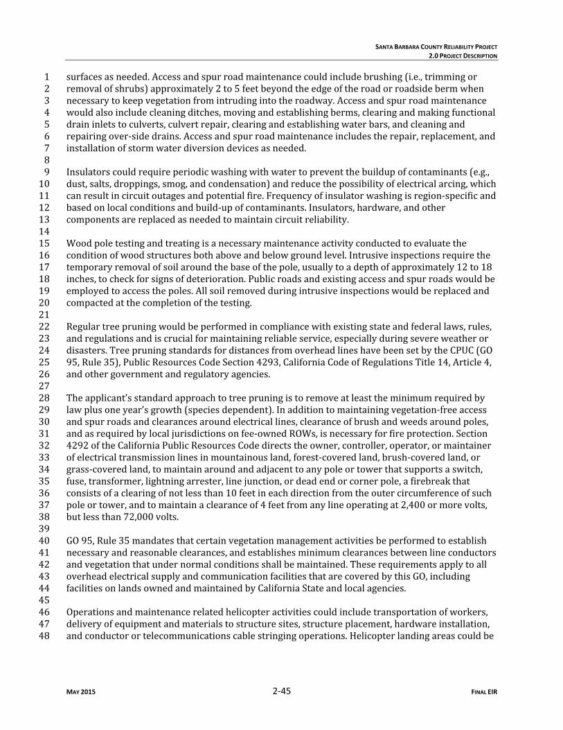
SANTA BARBARA COUNTY RELIABILITY PROJECT
2.0 PROJECT DESCRIPTION
MAY 2015 2‐45 FINAL EIR
surfacesasneeded.Accessandspurroadmaintenancecouldincludebrushing(i.e.,trimmingor1removalofshrubs)approximately2to5feetbeyondtheedgeoftheroadorroadsidebermwhen2necessarytokeepvegetationfromintrudingintotheroadway.Accessandspurroadmaintenance3wouldalsoincludecleaningditches,movingandestablishingberms,clearingandmakingfunctional4draininletstoculverts,culvertrepair,clearingandestablishingwaterbars,andcleaningand5repairingover‐sidedrains.Accessandspurroadmaintenanceincludestherepair,replacement,and6installationofstormwaterdiversiondevicesasneeded.78Insulatorscouldrequireperiodicwashingwithwatertopreventthebuildupofcontaminants(e.g.,9dust,salts,droppings,smog,andcondensation)andreducethepossibilityofelectricalarcing,which10canresultincircuitoutagesandpotentialfire.Frequencyofinsulatorwashingisregion‐specificand11basedonlocalconditionsandbuild‐upofcontaminants.Insulators,hardware,andother12componentsarereplacedasneededtomaintaincircuitreliability.1314Woodpoletestingandtreatingisanecessarymaintenanceactivityconductedtoevaluatethe15conditionofwoodstructuresbothaboveandbelowgroundlevel.Intrusiveinspectionsrequirethe16temporaryremovalofsoilaroundthebaseofthepole,usuallytoadepthofapproximately12to1817inches,tocheckforsignsofdeterioration.Publicroadsandexistingaccessandspurroadswouldbe18employedtoaccessthepoles.Allsoilremovedduringintrusiveinspectionswouldbereplacedand19compactedatthecompletionofthetesting.2021Regulartreepruningwouldbeperformedincompliancewithexistingstateandfederallaws,rules,22andregulationsandiscrucialformaintainingreliableservice,especiallyduringsevereweatheror23disasters.TreepruningstandardsfordistancesfromoverheadlineshavebeensetbytheCPUC(GO2495,Rule35),PublicResourcesCodeSection4293,CaliforniaCodeofRegulationsTitle14,Article4,25andothergovernmentandregulatoryagencies.2627Theapplicant’sstandardapproachtotreepruningistoremoveatleasttheminimumrequiredby28lawplusoneyear’sgrowth(speciesdependent).Inadditiontomaintainingvegetation‐freeaccess29andspurroadsandclearancesaroundelectricallines,clearanceofbrushandweedsaroundpoles,30andasrequiredbylocaljurisdictionsonfee‐ownedROWs,isnecessaryforfireprotection.Section314292oftheCaliforniaPublicResourcesCodedirectstheowner,controller,operator,ormaintainer32ofelectricaltransmissionlinesinmountainousland,forest‐coveredland,brush‐coveredland,or33grass‐coveredland,tomaintainaroundandadjacenttoanypoleortowerthatsupportsaswitch,34fuse,transformer,lightningarrester,linejunction,ordeadendorcornerpole,afirebreakthat35consistsofaclearingofnotlessthan10feetineachdirectionfromtheoutercircumferenceofsuch36poleortower,andtomaintainaclearanceof4feetfromanylineoperatingat2,400ormorevolts,37butlessthan72,000volts.3839GO95,Rule35mandatesthatcertainvegetationmanagementactivitiesbeperformedtoestablish40necessaryandreasonableclearances,andestablishesminimumclearancesbetweenlineconductors41andvegetationthatundernormalconditionsshallbemaintained.Theserequirementsapplytoall42overheadelectricalsupplyandcommunicationfacilitiesthatarecoveredbythisGO,including43facilitiesonlandsownedandmaintainedbyCaliforniaStateandlocalagencies.4445Operationsandmaintenancerelatedhelicopteractivitiescouldincludetransportationofworkers,46deliveryofequipmentandmaterialstostructuresites,structureplacement,hardwareinstallation,47andconductorortelecommunicationscablestringingoperations.Helicopterlandingareascouldbe48

SANTA BARBARA COUNTY RELIABILITY PROJECT
2.0 PROJECT DESCRIPTION
MAY 2015 2‐46 FINAL EIR
locatedwhereaccessbyroadisinfeasible.Inaddition,helicoptersmustbeabletolandwithinthe1applicant’sROWs,whichcouldincludelandingonaccessorspurroads.23Inadditiontoregularoperationsandmaintenanceactivities,theapplicantconductsawidevariety4ofemergencyrepairsinresponsetoemergencysituations,including,butnotlimitedto,damage5resultingfromhighwinds,storms,fires,othernaturaldisasters,andaccidents.Suchrepairscould6includereplacementofdownedpolesorlinesorre‐stringingconductors.Emergencyrepairscould7beneededatanytime.89Thetelecommunicationequipmentwouldbesubjecttomaintenanceandrepairactivitiesonanas‐10neededoremergencybasis.Activitiescouldincludereplacingdefectivecircuitboards,damaged11radioantennas,orfeedlinesandtestingtheequipment.Telecommunicationequipmentwouldalso12besubjecttoroutineinspectionandpreventativemaintenancesuchasfilterchange‐outsor13softwareandhardwareupgrades.1415Mostregularoperationsandmaintenanceactivitiesoftelecommunicationequipmentwouldbe16performedatsubstationsandwouldbeaccessedfromexistingaccessroadswithnosurface17disturbance.Accessroadmaintenancewouldbeperformedasdiscussedabove.1819Telecommunicationcablemaintenanceactivitieswouldincludepatrolling,testing,repairing,and20replacingdamagedcableandhardware.Mostregularmaintenanceactivitiesofoverheadfacilities21wouldbeperformedfromexistingaccessandspurroadswithnosurfacedisturbance,although22someactivitiescouldoccurinundisturbedareas.2324Repairsmadetoexistingfacilities,suchasrepairingorreplacingexistingcablesandrestringing25cables,couldoccurinundisturbedareas.Accessandhabitatrestorationmayberequiredforroutine26oremergencymaintenanceactivities.27282.5.2 Electric and Magnetic Fields 2930Electricandmagneticfields(EMFs)occurbothnaturallyandasaresultofhumanactivityacrossa31broadelectricalspectrum.Naturallyoccurringelectricandmagneticfieldsarecausedbythe32weatherandtheearth’sgeomagneticfield.Thefieldscausedbyhumanactivityresultfrom33technologicalapplicationoftheelectromagneticspectrumforusessuchascommunications,34appliances,andthegeneration,transmission,andlocaldistributionofelectricity.3536In1993,theCPUCimplementeddecisionD.9311‐013,whichrequiresutilitiestouse“low‐costor37no‐cost”EMFreductionmeasuresforEMFsassociatedwithelectricalfacilitiesthatrequire38certificationunderCPUCGO131‐D.Thedecisiondirectedutilitiestousea4percentbenchmarkfor39low‐costfieldreductionmeasures.ThisdecisionalsoimplementedanumberofEMFmeasurement,40research,andeducationprograms.TheCPUCdidnotadoptanyspecificnumericallimitsor41regulationofEMFlevelsrelatedtoelectricpowerfacilities.TheCPUC’sJanuary27,2006,decision42(D.06‐01‐042)affirmedthe1993decisiononthelow‐cost/no‐costpolicytomitigateEMFexposure43fornewutilitytransmissionandsubstationprojects.ForfurtherinformationaboutEMFsandCPUC44guidelines,referto:http://www.cpuc.ca.gov/PUC/energy/Environment/ElectroMagnetic+Fields.45 46
47

SANTA BARBARA COUNTY RELIABILITY PROJECT
2.0 PROJECT DESCRIPTION
MAY 2015 2‐47 FINAL EIR
SCEwouldincorporatethefollowinglow‐cost/no‐costmeasuresintothedesignoftheproposed1project:23
UtilizingsubtransmissionstructureheightsthatmeetorexceedSCE’spreferredEMFdesign4criteria. 5
Utilizingdouble‐circuitconstructionthatreducesspacingbetweencircuitsascompared6withsingle‐circuitconstructions.7
Arrangingconductorsofproposedsubtransmissionlineformagneticfieldreduction.8
Placingnewsubstationelectricalequipmentawayfromthesubstationpropertylinesclosest9topopulatedareas. 10
11Afterseveraldecadesofstudy,thereisstillalackofagreementinthescientificcommunity12regardingthepotentialhealthimpactsofhumanexposuretoEMFfromelectricpowerfacilities.13Additionally,therearenofederalorstatestandardslimitingpublicexposuretoEMFemittedby14electricalpowerlinesorsubstationfacilitiesintheState.Forthesereasons,EMFisnotevaluatedin15thisenvironmentalimpactreport(EIR)asanissuetobeaddressedundertheCalifornia16EnvironmentalQualityAct(CEQA),andnorelatedimpactsignificanceispresentedinthissection.17EMFinformationprovidedinthisEIRisintendedtoprovidethepublicwithabetterunderstanding18ofthetopic.19202.6 Applicant Proposed Measures 2122Toavoidandmitigatepotentialsignificantimpactstoenvironmentalresources,theapplicanthas23committedtoimplementingtheapplicantproposedmeasures(APMs)listedbelowinTable2‐9.2425Table 2‐9 Applicant Proposed Measures APMAQ‐1 ThefollowingcontrolmeasuresstatedintheVCAPCDVenturaCountyAirQuality
AssessmentGuidelinestominimizethegenerationoffugitivedust(PM10andPM2.5)wouldbeimplementedduringconstructionoftheproposedprojectasfeasible:1. Theareadisturbedbyclearing,grading,earthmoving,orexcavationoperations
shallbeminimizedtopreventexcessiveamountsofdust.
2. Pre‐grading/excavationactivitiesshallincludewateringtheareatobegradedorexcavatedbeforecommencementofgradingorexcavationoperations.Applicationofwater(preferablyreclaimed,ifavailable)shouldpenetratesufficientlytominimizefugitivedustduringgradingactivities.
3. Fugitivedustproducedduringgrading,excavation,andconstructionactivitiesshallbecontrolledbythefollowingactivities:
a) Alltrucksshallberequiredtocovertheirloads,asrequiredbyCaliforniaVehicleCode§23114.
b) Allgradedandexcavatedmaterial,exposedsoilareas,andactiveportionsoftheconstructionsite,includingunpavedon‐siteroadways,shallbetreatedtopreventfugitivedust.Treatmentshallinclude,butnotnecessarilybelimitedto,periodicwatering,applicationofenvironmentallysafesoilstabilizationmaterials,and/orroll‐compactionasappropriate.Wateringshallbedoneasoftenasnecessaryandreclaimedwatershallbeusedwheneverpossible.
4. Gradedand/orexcavatedinactiveareasoftheconstructionsiteshallbemonitored

SANTA BARBARA COUNTY RELIABILITY PROJECT
2.0 PROJECT DESCRIPTION
MAY 2015 2‐48 FINAL EIR
Table 2‐9 Applicant Proposed Measures by(indicatebywhom)atleastweeklyforduststabilization.Soilstabilizationmethods,suchaswaterandroll‐compaction,andenvironmentallysafedustcontrolmaterials,shallbeperiodicallyappliedtoportionsoftheconstructionsitethatareinactiveforoverfourdays.Ifnofurthergradingorexcavationoperationsareplannedforthearea,theareashouldbeseededandwatereduntilgrassgrowthisevident,orperiodicallytreatedwithenvironmentallysafedustsuppressants,topreventexcessivefugitivedust.
5. Signsshallbepostedonsitelimitingtrafficto15milesperhourorless.
6. Duringperiodsofhighwinds(i.e.,windspeedsufficienttocausefugitivedusttoimpactadjacentproperties),allclearing,grading,earthmoving,andexcavationoperationsshallbecurtailedtothedegreenecessarytopreventfugitivedustcreatedbyon‐siteactivitiesandoperationsfrombeinganuisanceorhazard,eitheroff‐siteoron‐site.Thesitesuperintendent/supervisorshallusehis/herdiscretioninconjunctionwiththeAPCDindeterminingwhenwindsareexcessive.
7. Adjacentstreetsandroadsshallbesweptatleastonceperday,preferablyattheendoftheday,ifvisiblesoilmaterialiscarriedovertoadjacentstreetsandroads.
8. Personnelinvolvedingradingoperations,includingcontractorsandsubcontractors,shouldbeadvisedtowearrespiratoryprotectioninaccordancewithCaliforniaDivisionofOccupationalSafetyandHealthregulations.
APMAQ‐2 ThefollowingcontrolmeasuresstatedintheVCAPCDVenturaCountyAirQualityAssessmentGuidelineswouldbeimplementedduringconstructionoftheProjectasfeasible:1. Minimizeequipmentidlingtime.
2. Maintainequipmentenginesingoodconditionandinpropertuneaspermanufacturers’specifications.
3. Lengthentheconstructionperiodduringsmogseason(MaythroughOctober),tominimizethenumberofvehiclesandequipmentoperatingatthesametime.
4. Usealternativelyfueledconstructionequipment,suchascompressednaturalgas,liquefiednaturalgas,orelectric,iffeasible.
APMBIO‐1 Pre‐constructionbiologicalsurveysforspecial‐statusplantsandwildlifewouldbeconducted0to30daysbeforethestartofconstructionbyaqualifiedbiologistinalllaydown/workareas.Ifaspecial‐statusspeciesisencountered,biologistswouldrecordthelocation,takeaphotograph,anddelineateabufferarea,asappropriate,whereactivitiesshouldberestrictedfortheprotectionoftheresource.Ifimpactstothespecial‐statusplant(s)orwildlifecannotbeavoided,SCEwouldconsultwiththeappropriateresourceagencyoragencies.
APMBIO‐2 Totheextentfeasible,SCEwouldminimizeimpactsandpermanentlosstonativevegetationtypes,vegetationthatmaysupportspecial‐statusspecies,andknownpopulationsofspecial‐statusplantsatconstructionsitesbyavoidingconstructionactivitiesinareasflaggedtobeavoided.Ifitisnotpossibletoavoidimpactstonativevegetation,aprojectrevegetationplanmaybepreparedinconsultationwiththeappropriateagenciesforareasofnativehabitattemporarilyimpactedduringconstruction.
APMBIO‐3 Biologicalmonitorswouldmonitorconstructionactivitiesinwildlifehabitatareasthatmaycontainspecial‐statusspecies,criticalhabitatforthosespecies,oruniqueresourcestoensuresuchspecies,habitat,orresourcesareavoided.
APMBIO‐4 SCEwouldconductproject‐widenestingbirdsurveys.SCEwould,iffeasible,removetrees,vegetation,subtransmissionstructures,andpolesoutsideofthenestingseason.If

SANTA BARBARA COUNTY RELIABILITY PROJECT
2.0 PROJECT DESCRIPTION
MAY 2015 2‐49 FINAL EIR
Table 2‐9 Applicant Proposed Measures atree,subtransmissionstructure,orpolecontainingaraptornestmustberemovedduringnestingseason,SCEbiologistswouldconsultwiththeappropriateresourceagencies.Ifworkisscheduledtotakeplaceincloseproximitytoanactivenest,appropriatenestingbuffersorothermeasureswouldbeestablishedbasedonconsultationwiththeappropriateresourceagenciesoranadaptivemanagementplantoaddressnestingbirds,whichwouldbesubjecttotheapprovaloftheCDFW.ThisProject‐specificNestingBirdManagementPlanwouldallowforimplementationofspecies‐specificbuffermodificationguidelinesprovidedbyaqualifiedutilityavianbiologist;nestbufferswouldbedeterminedbyspeciessensitivitytodisturbance,thenatureoftheconstructionactivity,andtheenvironmentalconditionssurroundingthenest.
APMBIO‐5 Duringthepre‐constructionsurveys,aqualifiedbiologistwouldidentifyanypotentialSanDiegodesertwoodratmiddenswithin50feetofproject‐relatedactivities.Atthediscretionofaqualifiedbiologist,anexclusionbufferwouldbeestablishedaroundanywoodratmiddensthatcanbeavoided,andtheseexclusionzoneswouldbeflaggedorfencedtoprotectthenestduringthebreedingseason(OctoberthroughJune).Ifawoodratmiddencannotbeavoided,anappropriateresourceagencywouldbeconsultedregardingapotentialbufferreduction.
APMBIO‐6 Apre‐construction,focusedburrowingowlprotocolsurveyshallbeconductednomorethan30dayspriortocommencementofground‐disturbingactivitieswithinsuitablehabitattodetermineifanyoccupiedburrowsarepresent.Ifoccupiedburrowsarefound,adequatebuffersshallbeestablishedaroundburrowsbasedonaproject‐specificnestingbirdmanagementplanorconsultationwiththeappropriateagencies.Ifoccupiedburrowscannotbeavoided,anappropriaterelocationstrategywouldbedevelopedinconjunctionwiththeCDFWandmayincludecollapsingburrowsoutsideofnestingseasonandusingexclusionarydevicestoreduceimpactstotheburrowingowl.Biologicalmonitorswouldmonitorallconstructionactivitiesthathavethepotentialtoimpactactiveburrows.
APMBIO‐7 TheNPDESConstructionGeneralPermitwouldrequireSCEtodevelopandimplementaStormWaterPollutionPreventionPlan(SWPPP),whichspecifiesbestmanagementpractices(BMPs)toavoidorminimizeimpactstowaterqualityandriparianhabitatduringconstruction.SeeAppendixBforexampleBMPsprovidedbySCE.
APMGEN‐1 TheapplicantwoulddevelopaWorkerEnvironmentalAwarenessPlan.Theapplicantwouldalsoprepareapresentationusedtotrainallsitepersonnelpriortothecommencementofwork.Arecordofalltrainedpersonnelwouldbekept.InadditiontoinstructiononcompliancewithAPMsandanymitigationmeasuresidentified,allconstructionpersonnelwouldalsoreceivethefollowing: Alistofphonenumbersfortheapplicant’senvironmentalspecialistpersonnel
associatedwiththeproposedproject(archaeologist,biologist,environmentalcompliancecoordinator,andregionalspillresponsecoordinator).
InstructionontheSantaBarbaraCountyAPCDandVenturaCountyAPCDfugitivedustrules.
Instructiononbiologicalresources(includingspecial‐statusspeciesandothersensitivehabitatsandresourcesthatcouldoccurinthevicinityoftheproposedproject);thelocationsofsensitiveresources;thelegalstatusandprotectionaffordedthesespecies;andthemeasurestobeimplementedforavoidanceandminimizationofimpactstotheresources.Penaltiesforviolationsofenvironmentallawswillalsobeincorporatedintothetraining.
Areviewofapplicablelocal,state,andfederalordinances,laws,andregulationspertainingtohistoricpreservation;adiscussionofdisciplinaryandotheractions

SANTA BARBARA COUNTY RELIABILITY PROJECT
2.0 PROJECT DESCRIPTION
MAY 2015 2‐50 FINAL EIR
Table 2‐9 Applicant Proposed Measures thatcouldbetakenagainstpersonsviolatinghistoricpreservationlawsandtheapplicantpolicies;areviewofarchaeology,history,prehistory,NativeAmericancultures,andpaleontologicalresourcesintheproposedprojectvicinity;andinstructionregardingwhattypicalculturalresourceslooklike.
Instructionregardingtheprocedurestobeimplementedshouldunanticipatedculturalresources(aswellaspaleontologicalresources)beencounteredduringconstructionactivities,includingstoppingworkinthevicinityofthefindandcontactingthearchaeologistorenvironmentalcompliancecoordinator,whowouldprovideguidanceonhowtoproceed.
Instructionregardingtheimportanceofmaintainingacleanconstructionsite,includingensuringthatallfoodscraps,wrappers,foodcontainers,cans,bottles,andothertrashfromtheproposedprojectaredepositedinclosedtrashcontainers.Trashcontainerswouldberemovedfromtheprojectareaasrequiredandwouldnotbepermittedtooverfill.
InstructionregardingtheindividualresponsibilitiesundertheCleanWaterAct,theprojectSWPPP,site‐specificBMPs,andthelocationofMaterialSafetyDataSheetsfortheproposedproject.
Instructionstonotifytheforemanandregionalspillresponsecoordinatorincaseofahazardousmaterialsspillorleakfromequipment,oruponthediscoveryofsoilorgroundwatercontamination.
Acopyofthetruckroutestobeusedformaterialdelivery.
Instructionthatnoncompliancewithanylaws,rules,regulations,ormitigationmeasurescouldresultinbeingbarredfromparticipatinginanyremainingconstructionactivitiesassociatedwiththeproposedproject.
APMCUL‐1 Potentialproject‐relatedeffectsonhistoricalresourcesmaybemitigatedorreducedtoalessthansignificantlevelbyimplementingSCE’sculturalresourcesUnanticipatedDiscoveryPlanandemployingoneormorestandardpracticemitigationscenariosincluding,butnotlimitedto: PrehistoricResources
- avoidwherefeasible(avoidancebydesign,preserveinplace,capping)
- minimize(reductionofAreaofDirectImpact/Effect)
- mitigate(historiccontextstatement,datarecovery)
HistoricResources
- avoidwherefeasible(avoidancebydesign,preserveinplace,capping)
- minimize(reductionofAreaofDirectImpact/Effect)
- mitigate(historiccontextstatement,datarecovery)
HistoricArchitecture/UtilityInfrastructure
- avoidwherefeasible(avoidancebydesign,preserveinplace)o
- minimize(reductionofAreaofDirectImpact/Effect)
- mitigate(historiccontextstatement,HistoricAmericanEngineeringRecord,HistoricAmericanBuildingSurvey,advancedCaliforniaDepartmentofParksandRecreationrecordation)

SANTA BARBARA COUNTY RELIABILITY PROJECT
2.0 PROJECT DESCRIPTION
MAY 2015 2‐51 FINAL EIR
Table 2‐9 Applicant Proposed Measures Theapplicant’sUnanticipatedDiscoveryPlanwoulddescribetheprocedurestobefollowedintheeventthatpreviouslyunidentifiedculturalresourcesarediscoveredduringconstructionoftheproposedproject.Ifpreviouslyunidentifiedculturalresourcesarediscoveredduringconstruction,personnelwouldbeinstructedtosuspendworkinthevicinityofthefind.TheresourcewouldthenbeevaluatedforlistingintheCRHRbyaqualifiedarchaeologist,and,iftheresourceisdeterminedtobeeligibleforlistingintheCRHR,eithertheresourcewouldbeavoidedorappropriatearchaeologicalprotectivemeasureswouldbeimplemented.Ifhumanskeletalremainsareuncoveredduringconstructionoftheproposedproject,theapplicantand/oritscontractorsshallimmediatelyhaltallworkintheimmediatearea,contacttheapplicableCountyCoronertoevaluatetheremains,andfollowtheproceduresandprotocolssetforthinSection15064.5(e)(1)oftheCEQAGuidelines.PerHealthandSafetyCode7050.5,uponthediscoveryofhumanremains,thereshallbenofurtherexcavationordisturbanceofthesiteoranynearbyareareasonablysuspectedtooverlieadjacentremains.IftheapplicableCountyCoronerdeterminesthattheremainsareNativeAmerican,itisanticipatedthatthecoronerwouldcontacttheNativeAmericanHeritageCommissioninaccordancewithHealthandSafetyCodeSection7050.5(c)andPublicResourcesCode5097.98(asamendedbyAssemblyBill2641).Inaddition,theapplicantshallensurethattheimmediatevicinitywheretheNativeAmericanhumanremainsarelocatedisnotdamagedordisturbedbyfurtherdevelopmentactivityuntiltheapplicanthasdiscussedandconferred,asprescribedinPublicResourcesCode5097.98,withthemostlikelydescendantsregardingtheirrecommendations.
APMCUL‐2 SCEshallprepareandimplementaPRMPthatwouldinclude,butnotbelimitedto:preconstructioncoordination;recommendedmonitoringmethods;emergencydiscoveryprocedures;samplinganddatarecoverymethods,ifneeded;museumstoragecoordinationforanyspecimensanddatarecovered;andreportingrequirements.ThePRMPwouldalsoprovideforsedimentscreening,fossilpreparation,curation,andpreparationofareportdetailingtheresultsofthework.Inaddition,thePRMPwouldspecifymonitoringrequirementssuchasthepresenceofapaleontologicalmonitorwhenworkisbeingperformedatformationswithhighpaleontologicalsensitivity.Ifveryfewornofossilremainsarefoundduringground‐disturbingactivities,monitoringtimecanbereducedorsuspendedentirely,perrecommendationsofthepaleontologicalfieldsupervisor.
APMCUL‐3 Aculturalresourcessurveyofthoseareasthatcouldnotbepreviouslyaccessedwouldbeconductedpriortothestartofconstruction.Thesesurveyswouldidentifyand/oraddressanypotentialsensitiveculturalresourcesthatmaybeimpactedbytheProject,includingthesubstationsites,subtransmissionlineandtelecommunicationcableroutes,wirestringinglocations,accessandspurroads,drillingandcranepads,andstagingyards.
APMGEO‐1 Basedonthefindingsofthegeotechnicalanalysis,SCEwoulddesignprojectcomponentstominimizethepotentialforlandslides,lateralspreading,subsidence,liquefaction,orcollapse.Measuresthatmaybeusedtominimizeimpactscouldinclude,butarenotlimitedto:stabilizationfills,retainingwalls,slopecoverings,removalofunstablematerials,avoidanceofhighlyunstableareas,constructionofpilefoundations,groundimprovementsofliquefiablezones,installationofflexiblebusconnections,andincorporationofslackincables.
APM Constructionactivitieswillbeconductedorphasedtoensurethatthenoisegenerated

SANTA BARBARA COUNTY RELIABILITY PROJECT
2.0 PROJECT DESCRIPTION
MAY 2015 2‐52 FINAL EIR
Table 2‐9 Applicant Proposed Measures NOISE‐1 duringconstructionwouldnotexceedsignificancethresholdsordurationsidentifiedby
theCityofCarpinteriaResolutionNo.408;theCountyofVenturanoiseregulationssetforthintheCounty’sConstructionNoiseThresholdCriteriaandControlPlan;ortheCountyofSantaBarbaraEnvironmentalThresholdsandGuidelinesManual.
APMNOISE‐2
Equipmentandtrucksusedforprojectconstructionshallemploythebestavailablenoisecontroltechniquestotheextentfeasible.
APMNOISE‐3
Stationarynoisesourcesshallbelocatedasfarfromadjacentnoisesensitivereceptorsasreasonablypossibleandshallbeenclosediffeasible.
APMNOISE‐4
Wherefeasible,temporaryportablesoundbarrierswouldbedeployedwhereconstructionactivitieswouldcausenoiselevelsatsensitivereceptorlocationstobeinexcessofanapplicablecriteriathreshold.ForpurposesofthisAPM,schoolswouldonlybeconsideredsensitivereceptorlocationsduringinstructionhours.
APMNOISE‐5
Atleast2weekspriortotheanticipatedstartofconstructionataparticularlocation,SCEwillnotifyallpropertyownerswithin300feetofthatlocationthatconstructionactivitiesareabouttocommenceatthatlocation.
Source:SCEdocumentationsubmitted2012‐2014Key:APCD AirPollutionControlDistrictAPM ApplicantproposedmeasureBMP BestmanagementpracticeCDFW CaliforniaDepartmentofFishandWildlifeCRHR CaliforniaRegisterofHistoricResourcesPM10 Particles10micronsorlessindiameterPM2.5 Particles2.5micronsorlessindiameterPRMP ProposedresourcemanagementplanSCE SouthernCaliforniaEdisonSWPPP StormwaterpollutionpreventionplanVCAPCD VenturaCountyAirPollutionControlDistrict12.7 Permitting and Consultation Requirements 23Table2‐10liststhefederal,state,andlocalpermitsandconsultationsthatmayberequiredfor4constructionandoperationoftheproposedproject.56Table 2‐10 Consultation and Permitting Requirements Agency / Group Jurisdiction Consultation or Permit
Federal UnitedStatesArmyCorpsofEngineers
WorkwithinWatersoftheUnitedStates,includingwetlands
ConsultationwiththeUSACE,RWQCB,CDFW,andUSFWSforaCleanWaterActSection404permit
UnitedStatesFishandWildlifeService
Threatenedorendangeredspeciesandconservationplans
Takeauthorization(ifrequired)andconsultationwiththeUSFWS.ConsultationforSection7or10oftheFederalEndangeredSpeciesAct.
NationalMarineFisheriesService
Alterationstosteelheaddesignatedcriticalhabitat
ConsultationtodetermineappropriatebestmanagementpracticesforwideninganaccessroadinSuttonCreek.
UnitedStatesForestService
UnitedStatesNationalForestSystemland,LosPadresNationalForest
PermissiontoconstructcomponentswithintheLosPadresNationalForest.NEPAreviewforthesecomponentsaswellasadditionalSCEworkonforestlands,whichisnotrelatedtotheproposedproject,willbeconductedseparatelybyLosPadresNationalForestServicestaff.

SANTA BARBARA COUNTY RELIABILITY PROJECT
2.0 PROJECT DESCRIPTION
MAY 2015 2‐53 FINAL EIR
Table 2‐10 Consultation and Permitting Requirements Agency / Group Jurisdiction Consultation or Permit
FederalAviationAdministration
AircraftoperationandsafetyinUnitedStatesairspace
ConsultationtodeterminewhetherCongestedAreaPlanapprovalforhelicopterexternal‐loadoperationsisrequired.ConsultationtoensurecompliancewithFederalAviationRegulationsPart77(ObjectsAffectingNavigableAirspace).
State CaliforniaPublicUtilitiesCommission
CEQAreviewandoverallapprovaloftheproposedproject
PermittoConstructforconstructionofelectricsubtransmissionlinefacilitiesdesignedforoperationat66kV.
CaliforniaDepartmentofFishandWildlife
Threatenedorendangeredspeciesandconservationplans
Takeauthorization(ifrequired)andconsultationwiththeUSFWS.ConsultationforSection2081oftheCaliforniaEndangeredSpeciesAct.ConsultationforSection1600oftheFishandGameCode(streambedalterationagreement).
CaliforniaDepartmentofTransportation
ActsonbehalfoftheFederalDepartmentofTransportationpursuanttoCaliforniaStreetsandHighwaysCode660to711.21andCaliforniaCodeofRegulations1411.1to1411.6.
Caltransrequiresthatallworkdonewithin,underoraboveastateorinterstatehighwayright‐of‐wayobtainanencroachmentpermit.ATransportationPermitrequiredforoversizeand/oroverweighttruckloadsthatexceedthelimitsofalegalloadasdefinedbyDivision15oftheCaliforniaVehicleCode.
CaliforniaStateWaterResourcesControlBoard
StormwaterdischargesandCleanWaterActSection401permit
NoticeofIntenttoobtaincoverageundertheGeneralPermitforStormWaterDischargesAssociatedwithConstructionandLandDisturbanceActivities,Order2009‐0009‐DWQasamendedbyOrder2010‐0014‐DWQandSection401PermitassociatedwithissuanceofaCleanWaterActSection404Permit
StateHistoricPreservationOffice,NativeAmericanHeritageCommission
Historic,cultural,andarchaeologicalresources
Consultationregardingknownculturalresources.ConsultationregardingthelistingofculturalorhistoricresourcesintheNationalRegisterofHistoricPlacesorCaliforniaRegisterofHistoricalResources.
Regional and Local SantaBarbaraCountyPlanningandDevelopmentDepartment
CEQAreviewandapprovalofworkwithintheCaliforniaCoastalZone
CoastalDevelopmentPermitforSegment3AandportionsofSegment4.
CityofCarpinteriaCommunityDevelopmentDepartment
CEQAreviewandapprovalofworkwithintheCaliforniaCoastalZone
CoastalDevelopmentPermitforaportionofSegment3A.
CentralCoastandLosAngelesRegionalWaterQualityControlBoard
NationalPollutantDischargeEliminationSystempermitting
AsdirectedbyStateWaterResourcesControlBoard,monitordevelopmentandimplementationofSWPPPsandotheraspectsoftheNationalPollutantDischargeEliminationSystempermitand401certificationprogram.SWPPPsarerequiredforstormwaterdischargesassociatedwithconstructionactivitiesthatdisturbmorethan1acreofland.

SANTA BARBARA COUNTY RELIABILITY PROJECT
2.0 PROJECT DESCRIPTION
MAY 2015 2‐54 FINAL EIR
Table 2‐10 Consultation and Permitting Requirements Agency / Group Jurisdiction Consultation or Permit
VenturaCountyAirPollutionControlDistrictandSantaBarbaraCountyAirPollutionControlDistrict
Airpollutionandgreenhousegasemissionsincludingfugitivedust
City/County(otherministerial)
Floodcontrolareas,temporarylandoccupancyandstagingareas,grading,excavation,afterhourswork,encroachment,treetrimming/removal,andtrafficcontrol/laneclosures
Permitsforcrossingfloodcontrolareas,temporaryuse/occupancy,grading,excavationandshoring,andafterhourswork(ifrequired)
Source:SCEdocumentationsubmitted2012‐2014Source:SCE2012Key:Caltrans CaliforniaDepartmentofTransportationCDFW CaliforniaDepartmentofFishandWildlifeCEQA CaliforniaEnvironmentalQualityActkV kilovoltNEPA NationalEnvironmentalPolicyActRWQCB RegionalWaterQualityControlBoardSCE SouthernCaliforniaEdisonSWPPP StormWaterPollutionPreventionPlanUSACE U.S.ArmyCorpsofEngineersUSFWS U.S.FishandWildlifeService1