20 cooperative lt e
TRANSCRIPT

8/13/2019 20 Cooperative Lt e
http://slidepdf.com/reader/full/20-cooperative-lt-e 1/10
INTERNATIONAL JOURNAL OF COMMUNICATION SYSTEMS Int. J. Commun. Syst. (2012)Published online in Wiley Online Library (wileyonlinelibrary.com). DOI: 10.1002/dac.2423
Cooperative communications for LTE-advanced—relayand CoMP‡
Young-Han Nam1, *,† , Lingjia Liu2 and Jianzhong (Charlie) Zhang1
1Samsung Telecommunications America, Richardson, TX, USA2 Department of Electrical Engineering and Computer Science, University of Kansas, Lawrence, KS, USA
SUMMARY
The Long Term Evolution-Advanced (LTE-A) system is currently under development to allow for signif-icantly higher spectral efficiency and data throughput than the LTE systems. In a wireless system basedon orthogonal frequency division multiplexing with frequency reuse factor one, the achievable cell spectral
efficiency is often limited by the inter-cell interference or coverage shortage of base stations. In LTE-A, coor-dinated multi-point transmission/reception (a.k.a. multi-cell MIMO or base station cooperation) and relayingtechnologies are being introduced to clear these major performance hurdles. In this paper, cooperative com-munication technologies being discussed in LTE-A systems are presented, together with considerations onsystem design. Copyright © 2012 John Wiley & Sons, Ltd.
Received 2 October 2011; Revised 16 April 2012; Accepted 21 July 2012
KEY WORDS: cooperative communications; relay; CoMP; LTE
1. INTRODUCTION
Next generation wireless communication systems, named International Mobile Telecommunications-
Advanced (IMT-A) systems, target to achieve another major advance from the current 3G system, interms of achieving 1 Gbps for downlink (DL) and 500 Mbps for uplink throughput. For this purpose,
the 3GPP society is currently developing Long Term Evolution-Advanced (LTE-A) standard [2] as
an evolution of the already frozen LTE Release 8 standard [3].
From information theory we know that the ultimate performance measure of a communication
system is the spectral efficiency [4]. Furthermore, the spectral efficiency of a communication link is
determined by signal-to-noise-plus-interference ratio (SINR) at a receiver. To be specific, the SINR
at a receiver can be written as, SINR D P=.I C N /, where P is power seen at the receiver of a
signal transmitted by a transmitter, I is interference power from other interfering sources and N is
variance of an additive white Gaussian noise signal. In most cases, a low SINR is caused by either
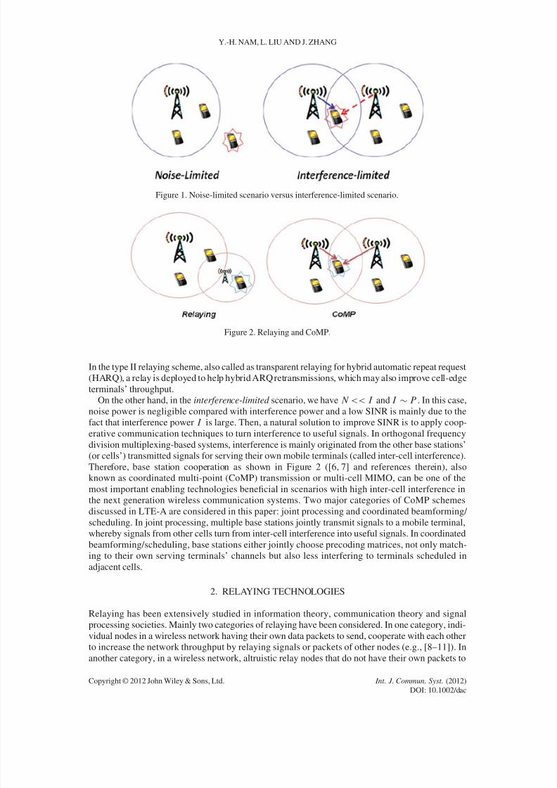
of two scenarios: noise-limited scenario and interference-limited scenario [5] as shown in Figure 1.
In the noise-limited scenario, we have I << P and P N . This implies that interference is neg-
ligible compared with noise variance and a low SINR is mainly caused by the fact that the received
signal strength of the targeted signal, P , is low. A natural solution to boost the SINR is to increase
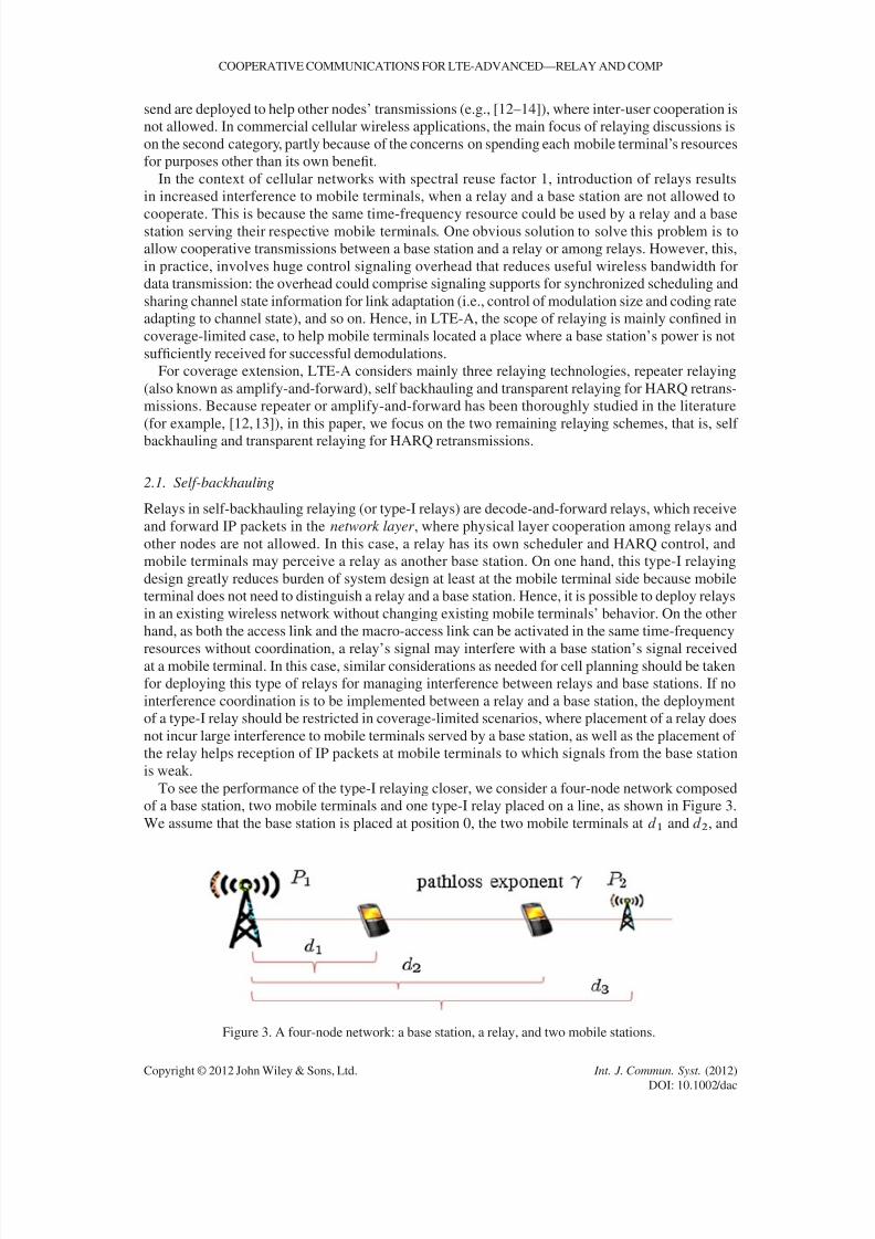
P utilizing a relaying technology as shown in Figure 2. Two classes of relaying schemes considered
in LTE-A are studied in this paper: types I and II. In the type I relaying scheme, also known as
self-backhauling, a relay is seen as a serving base station at noise-limited mobile terminals, and
it can forward Internet protocol (IP) packets to these mobile terminals and to a base station.
*Correspondence to: Young-Han Nam, Samsung Telecommunications America, Richardson, TX, USA.†E-mail: [email protected]‡Part of this work has been presented in [1].
Copyright © 2012 John Wiley & Sons, Ltd.
8/13/2019 20 Cooperative Lt e
http://slidepdf.com/reader/full/20-cooperative-lt-e 2/10
8/13/2019 20 Cooperative Lt e
http://slidepdf.com/reader/full/20-cooperative-lt-e 3/10
COOPERATIVE COMMUNICATIONS FOR LTE-ADVANCED—RELAY AND COMP
send are deployed to help other nodes’ transmissions (e.g., [12–14]), where inter-user cooperation is
not allowed. In commercial cellular wireless applications, the main focus of relaying discussions is
on the second category, partly because of the concerns on spending each mobile terminal’s resources
for purposes other than its own benefit.
In the context of cellular networks with spectral reuse factor 1, introduction of relays results
in increased interference to mobile terminals, when a relay and a base station are not allowed to
cooperate. This is because the same time-frequency resource could be used by a relay and a basestation serving their respective mobile terminals. One obvious solution to solve this problem is to
allow cooperative transmissions between a base station and a relay or among relays. However, this,
in practice, involves huge control signaling overhead that reduces useful wireless bandwidth for
data transmission: the overhead could comprise signaling supports for synchronized scheduling and
sharing channel state information for link adaptation (i.e., control of modulation size and coding rate
adapting to channel state), and so on. Hence, in LTE-A, the scope of relaying is mainly confined in
coverage-limited case, to help mobile terminals located a place where a base station’s power is not
sufficiently received for successful demodulations.
For coverage extension, LTE-A considers mainly three relaying technologies, repeater relaying
(also known as amplify-and-forward), self backhauling and transparent relaying for HARQ retrans-
missions. Because repeater or amplify-and-forward has been thoroughly studied in the literature
(for example, [12, 13]), in this paper, we focus on the two remaining relaying schemes, that is, self
backhauling and transparent relaying for HARQ retransmissions.
2.1. Self-backhauling
Relays in self-backhauling relaying (or type-I relays) are decode-and-forward relays, which receive
and forward IP packets in the network layer , where physical layer cooperation among relays and
other nodes are not allowed. In this case, a relay has its own scheduler and HARQ control, and
mobile terminals may perceive a relay as another base station. On one hand, this type-I relaying
design greatly reduces burden of system design at least at the mobile terminal side because mobile
terminal does not need to distinguish a relay and a base station. Hence, it is possible to deploy relays
in an existing wireless network without changing existing mobile terminals’ behavior. On the other
hand, as both the access link and the macro-access link can be activated in the same time-frequency
resources without coordination, a relay’s signal may interfere with a base station’s signal receivedat a mobile terminal. In this case, similar considerations as needed for cell planning should be taken
for deploying this type of relays for managing interference between relays and base stations. If no
interference coordination is to be implemented between a relay and a base station, the deployment
of a type-I relay should be restricted in coverage-limited scenarios, where placement of a relay does
not incur large interference to mobile terminals served by a base station, as well as the placement of
the relay helps reception of IP packets at mobile terminals to which signals from the base station
is weak.
To see the performance of the type-I relaying closer, we consider a four-node network composed
of a base station, two mobile terminals and one type-I relay placed on a line, as shown in Figure 3.
We assume that the base station is placed at position 0, the two mobile terminals at d 1 and d 2, and
Figure 3. A four-node network: a base station, a relay, and two mobile stations.
Copyright © 2012 John Wiley & Sons, Ltd. Int. J. Commun. Syst. (2012)
DOI: 10.1002/dac

8/13/2019 20 Cooperative Lt e
http://slidepdf.com/reader/full/20-cooperative-lt-e 4/10
Y.-H. NAM, L. LIU AND J. ZHANG
the relay at d 3, where d 1 < d 2 < d 3. We further assume that a channel gain between two nodes is
determined by pathloss only, and the pathloss exponent is . In addition, the base station and the
relay transmits signals with power P 1 and P 2.
Without the relay, the SINRs at the two mobile terminals are SINR1 D d 1 P 1=N and
SINR2 D d 2 P 1=N , respectively. With the introduction of the relay, we suppose that the base
station transmits signals to mobile terminal 1 and the relay serves mobile terminal 2 in the same
frequency band. In type-I relaying, the relay and the base station do not cooperate in the phys-ical layer, and hence the relay’s signal and the base station’s signal interfere with each other
at each mobile station. SINRs with the relay are, SINR0
1 D d 1 P 1=.N C .d 3 d 1/ P 2/
and SINR0
2 D .d 3 d 2/ P 2=.N C d 2 P 1/, respectively. Then, the network throughput val-
ues 1 and 2 with and without the relay are, 1 D log2.1 C SINR1/ C log2.1 C SINR2/ and
2 D ˛
log2.1C SINR0
1/C log2.1C SINR0
2/
bits/sec/Hz, respectively, where ˛ 2 .0, 1/ is a
fraction of time available for transmissions to mobile terminals.
If d 3 >> d 1 and d 3d 2 << d 2, we have SINR0
1 SINR1 and SINR0
2 > SINR2, hence deploying
a type-I relay could potentially give throughput gain in the network, thanks to the extended cover-
age to mobile terminal 2. However, this is not always the case. Suppose that d 2 D 3d 1, d 3 D 2d 1,
P 2 D 0.1P 1 and D 3. Then, we have SINR0
1 < SINR1 and SINR0
2 SINR2 and hence deploy-
ing a type-I relay decreases the network throughput owing to an increased interference to mobile
terminal 1.
2.2. Transparent relaying for hybrid automatic repeat request retransmissions
As another attempt to extend coverage of LTE-A systems while minimizing impacts on the system
design and overhead, a transparent relaying scheme for HARQ retransmissions (also known as
type-II relaying) has been introduced. In type-II relaying, relays are activated only for HARQ
retransmissions for mobile terminals. For example, a relay listens to DL transmissions from a base
station and uplink ACK/NACK messages from mobile terminals. When the relay decodes a NACK
message from a mobile terminal that has decoded the associated packet to the NACK message,
it can jointly transmit retransmission signals intended for the mobile terminal together with the
base station.
For analysis of the type-II relaying, we consider a three-node network composed of a base station,
a type-II relay and a mobile terminal. We assume that the first round error probability of a packet
transmitted by the base station at the mobile terminal is p1, and the second round probability at the
mobile terminal when the relay does not help is p2. Furthermore, we assume that the second-round
error probability at the mobile terminal when the relay helps is p 0
2. The throughput values and 0,
with and without the type-II relay can be respectively calculated as D .1 p1/ C p1.1 p2/=2and 0 D .1p1/Cp1.1p0
2/=2 packets per time slot. Hence, deploying a type-II relay will have
throughput gain if p0
2 < p2. There are multiple ways of realizing p0
2 < p2. In one example, only the
relay transmits packet in the second round, as the access link is assumed to have a better channel
than the macro-access link. In another example, both the relay and the base station transmits the
same signals, so that the mobile terminal receiver can get benefits from increased receive power.
2.3. Numerical evaluations
To numerically compare the received SINR distribution at each user equipment (or geometry
distribution) with and without type-I relay in a cellular environment, a system-level evaluation is
performed with parameters listed in Table I, which are the parameters used in 3GPP case 1 [2]. In
3GPP case 1, base stations are located at the center of 19 cell sites of a hexagonal grid, and each
hexagon is partitioned into three sectors. 10 mobiles are randomly dropped in each sector, according
to a uniform distribution.
Figure 4 shows the geometry comparison results, with two different relay deployment scenarios
In Figure 4(a), relays are located at 1/3 inter-site distance in each sector from every base station,
whereas in Figure 4(b) relays are located at 1/2 inter-site distance. For evaluating user geometry
distribution, firstly a serving node is selected for each mobile out of all the transmission points (i.e.,
base stations and relays) in the network, where the serving node is the transmission point whose
Copyright © 2012 John Wiley & Sons, Ltd. Int. J. Commun. Syst. (2012)
DOI: 10.1002/dac

8/13/2019 20 Cooperative Lt e
http://slidepdf.com/reader/full/20-cooperative-lt-e 5/10
COOPERATIVE COMMUNICATIONS FOR LTE-ADVANCED—RELAY AND COMP
Table I. Simulation parameters.
Parameter Assumption
Cellular layout Hexagonal grid, 19 sites, 3 sectorsper site, wraparound
Inter-site distance 500 mBS total power 46 dBm
Relay total power 30 dBmBS antenna pattern Directional:
A.'/ D min
12
''3dB
2, Am
'3dB D 70ı, Am D 25 dB
Relay antenna pattern Omni-directionalNoise figure at UE 9 dBDistance-dependent path loss L D I C 37.6 log 10..R/, R in
kilometers, I D 128.1—2 GHzMinimum distance between UE and cell >D 35 metersStandard deviation of lognormal shadowing 8 dB for macro cellPenetration loss 20 dBMobile speeds 3 km/h
(a) Relays placed at 1/3 ISD from a base station
(b) Relays placed at 1/2 ISD from a base station
Figure 4. User geometry distributions depending on relay placements.
Copyright © 2012 John Wiley & Sons, Ltd. Int. J. Commun. Syst. (2012)
DOI: 10.1002/dac

8/13/2019 20 Cooperative Lt e
http://slidepdf.com/reader/full/20-cooperative-lt-e 6/10
Y.-H. NAM, L. LIU AND J. ZHANG
signal is received with the highest power at the mobile. Then, each mobile’s SINR is evaluated by
taking into account the received signal powers from the serving link and the interfering links (i.e., all
the DL communication links to the mobile other than the serving link). Collecting all the mobiles’
SINR, the geometry distribution is found. In Figure 4(a), where relays are placed closer to each
base station, the relay placement gives worse geometry distribution than a network without relays
owing to more interference caused by relays, whereas in Figure 4(b), where relays are placed
further away from each base station, the relay placement gives better geometry distribution thanks tocoverage extension.
3. COORDINATED MULTIPOINT TRANSMISSIONS
In this section, two important classes of CoMP transmission schemes are introduced and discussed.
3.1. Joint processing
In the class of joint processing/transmission, multiple base stations (or transmission points or cells)
jointly transmit signals to a single mobile terminal to improve the received signal quality or actively
cancel interference for other mobile terminals, or both. In this case, data intended for a particular
mobile terminal is shared among different cells (cell 1 and cell 2) and is jointly processed at these
cells. As a result of this joint processing, received signals at the intended mobile terminal will becoherently or non-coherently added up together.
As shown in Figure 5, we assume that mobile user 1 (M1) is receiving signals from the three cells:
Cell 1, Cell 2, and Cell 3 (denoted as C1, C2 and C3, respectively). Assume H i1 is the channel gain
from C i to M1, the received signal Y 1 at M1 can be expressed as Y 1 D H 11W 1X 1 C H 21W 2X 2 CH 31W 3X 3 C Z1, where X i is the signal transmitted at C i , W i is the precoding matrix at C i , and
Z1 is the additive white Gaussian noise at the receiver. If each cell is serving to his/her own mobile
terminals, the signals will interference with each other, then the SINR for M1 can be expressed as,
SINR1 D kH 11W 1k2 P 1=
kH 21W 2k
2 P 2CkH 31W 3k2 P 3CN
,
where P i is the transmitted power of X i at C i , and N is the noise power.
Figure 5. CoMP joint processing.
Copyright © 2012 John Wiley & Sons, Ltd. Int. J. Commun. Syst. (2012)
DOI: 10.1002/dac

8/13/2019 20 Cooperative Lt e
http://slidepdf.com/reader/full/20-cooperative-lt-e 7/10
COOPERATIVE COMMUNICATIONS FOR LTE-ADVANCED—RELAY AND COMP
Considering a CoMP joint processing system where C1, C2 and C3 form a CoMP cluster, M1 is
then being simultaneously served by all the three cells belonging to the CoMP cluster. Under this
assumption, we have X i D X , i D 1, 2, 3. Accordingly, the received signal at M1 can be expressed
as Y 1 D H 11W 1X C H 21W 2X C H 31W 3X C Z1. Therefore, the SINR of M1 can be computed as,
SINR0
1 D H 11W 1p P 1CH 21W 2p P 2CH 31W 3p P 32
=N .
It is clear that SINR1 is always upper-bounded by SINR0
1, and CoMP joint processing will always
bring an SINR gain compared with single-cell operation. However, this gain is not free. Note that
SINR1 is obtained under the assumption that each cell is serving his/her own mobile user whereas
SINR0
1 is obtained under the assumption that three cells are serving one mobile user. Therefore,
mobile terminals under CoMP joint processing are occupying more system resources than the
single-cell mobile terminals. This is actually one of the biggest hidden costs of CoMP joint
processing. Taking this hidden cost in to account, assuming symmetric channel conditions, the total
throughputs of the single-cell operation and the CoMP joint processing are 3 log2.1 C SINR1/ and
log2.1 C SINR0
1/, respectively. Therefore, it is not worth to perform CoMP joint processing for
cell-center mobile terminals where the value of SINR1 is high. Under this situation, the cost of
system resource is high, whereas SINR improvement is marginal.
This analysis is based on the fact that only one mobile user is served by the CoMP cluster,
which is called CoMP single-user (SU) MIMO mode. A more involved operation mode is theCoMP multi-user (MU) MIMO mode, where multiple mobile terminals are joint served by the
CoMP cluster.
3.2. Coordinated beamforming/scheduling
In the class of coordinated scheduling and/or beam-forming, data to mobile terminal is instanta-
neously transmitted from one of the transmission points (cells), whereas the scheduling decisions
are coordinated to control the interference generated in a set of coordinated cells. In other words, as
shown in Figure 6, the data intended for a particular mobile terminal, say M1, is transmitted only
by C1; however, C2 will choose to serve its mobile terminals in such a way that it will create little
interference to M1. This technology is also known as ‘interference mitigation’ in the signal process-
ing society and some methods to mitigate interference through different signal spaces can be found
in [15] and [16].
Assume two mobile terminals, M1 and M2, are close to each other and are served by C1
and C2, respectively. The received signals, Y 1 and Y 2, of M1 and M2 can be written as, Y 1 DH 11W 1X 1 C H 21W 2X 2 C Z1, Y 2 D H 12W 1X 1 C H 22W 2X 2 C Z2. Accordingly, the received
SINR for M1 and M2 can be expressed as, SINR1 D kH 11W 1k2 P 1=
kH 21W 2k
2 P 2CN
and
SINR2 D kH 22W 2k2 P 2=
kH 12W 1k
2 P 1CN
, respectively.
Figure 6. CoMP coordinated beamforming/scheduling.
Copyright © 2012 John Wiley & Sons, Ltd. Int. J. Commun. Syst. (2012)
DOI: 10.1002/dac
8/13/2019 20 Cooperative Lt e
http://slidepdf.com/reader/full/20-cooperative-lt-e 8/10
Y.-H. NAM, L. LIU AND J. ZHANG
In single-cell operation, the precoding vector W i of MS i is chosen such that the received signal
strength from the serving cell are maximized:
W 01 D arg maxW 1 kH 11W 1k
2 P 1=kH 21W 2k
2 P 2CN
,
W 02 D arg maxW 2 kH 22W 2k
2 P 2= kH 12W 1k2 P 1CN .
When M1 and M2 are close, it is likely that both the pairs ¹H 11, H 12º and ¹H 21, H 22º are
correlated. Therefore, W 0 applied in C1 is actually causing a large inter-cell interference to the
received signal of M2 and vice versa.
In coordinated beamforming/scheduling, the precoding vectors are joint optimized such that the
SINRs at the mobile terminals are improved. That is, the CoMP cluster joint choose the precoding
vectors and scheduling decisions taking into account the inter-cell interference.
3.3. Joint processing versus coordinated beamforming /scheduling
It is expected that CoMP joint processing will bring more significant system improvement at a
higher implementation cost. For example, in CoMP joint processing, the data together with channel
related information for different mobile users needs to be exchanged among the cells within CoMPcluster. Differently from relaying technology, this data exchange can be done in wired backhaul;
however, this still cause additional latency and impose stringent requirements for backhaul tech-
nologies. On the other hand, in coordinated beamforming/scheduling, unlike joint processing, data
for an intended mobile user is only transmitted from its serving cell. This way, only channel state
information and scheduling decisions are needed to be exchanged among the cells. This reduces
the system complexity and backhaul traffic. Furthermore, joint processing is more sensitive to the
channel feedback errors as opposed to the coordinated beamforming/scheduling, and it is difficult to
ensure that the signals from different cells are constructively added at the receiver. Because of these
reasons, current 3GPP community focuses more on the CoMP coordinated beamforming/scheduling
for LTE-A systems. However, joint processing can be still promising if some of the practical issues
can be resolved.
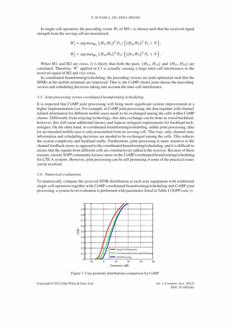
3.4. Numerical evaluations
To numerically compare the received SINR distribution at each user equipment with traditional
single-cell operation together with CoMP coordinated beamforming/scheduling and CoMP joint
processing, a system-level evaluation is performed with parameters listed in Table I (3GPP case 1).
-10 0 10 20 30 400
0.1
0.2
0.3
0.4
0.5
0.6
0.7
0.8
0.9
1
C D F
Geometry (dB)
Single-Cell Operation
Coordinated Beamforming/Scheduling
Joint Processing
Figure 7. User geometry distributions comparison for CoMP.
Copyright © 2012 John Wiley & Sons, Ltd. Int. J. Commun. Syst. (2012)
DOI: 10.1002/dac

8/13/2019 20 Cooperative Lt e
http://slidepdf.com/reader/full/20-cooperative-lt-e 9/10
COOPERATIVE COMMUNICATIONS FOR LTE-ADVANCED—RELAY AND COMP
Figure 7 shows the comparison results for user geometry distribution. The results suggest that both
CoMP CB/CS and CoMP JP can help to improve system performance significantly. With the help
of CoMP, the system geometry distribution is shifted up with more gains obtained at the cell-edge
users as opposed to cell-center users. These evaluation results are aligned with previous analysis.
4. CONCLUSION
In this paper, cooperative communication technologies being considered in LTE-A have been intro-
duced. As solutions for coverage limitation and inter-cell interference, relaying and coordinated
multi-point (CoMP) transmission have respectively been discussed, and their performances and
design challenges have been investigated.
REFERENCES
1. Nam YH, Liu L, Wang Y, Zhang J, Cho J, Han JK. Cooperative communication technologies for LTE-Advanced.
2010 IEEE International Conference on Acoustics Speech and Signal Processing, Dallas, TX, USA, March 2010;
5610–5613.
2. 3GPP TR 36814. Evolved Universal Terrestrial Radio Access (E-UTRA); Further Advancements for E-UTRA
Physical Layer Aspects Physical Channels and Modulation, ver 9.0.0, March 2010.
3. 3GPP TS 36211. Evolved Universal Terrestrial Radio Access (E-UTRA); Physical Channels and Modulation,
ver 9.1.0, March 2010.4. Cover TM, Thomas JA. Elements of Information Theory. Wiley: New York, NY, USA, 1991.
5. Tse D, Viswanath P. Fundamentals of Wireless Communications. Cambridge University Press: New York, NY, USA,
2005.
6. Zhang H, Mehta NB, Molisch AF, Zhang J, Dai H. Asynchronous interference mitigation in cooperative base station
systems. IEEE Transactions on Wireless Communications 2008; 7(1):155–165.
7. Gesbert D, Hanly S, Huang H, Shamai S, S, Simeone O, Yu W. Multi-cell MIMO cooperative networks: a new look
at interference. IEEE Journal on Selected Areas in Communications 2010; 28(9):1380–1408.
8. Gupta P, Kumar PR. The capacity of wireless networks. IEEE Transactions on Information Theory 2000;
46(3):388–404.
9. Sendonaris A, Erkip E, Aazhang B. User Cooperation diversity - part i: system description. IEEE Transactions
Communications 2003; 51(11):1927–1938.
10. Nam YH, Azarian K, El Gamal H, Schniter P. Cooperation through ARQ. IEEE 6th Workshop on Signal Processing
Advances in Wireless Communications, New York, NY, USA, 2005; 1023–1027.
11. Jia XD, Fu HY, Yang LX, Zhao LQ. Superposition coding cooperative relaying communications: outage performance
analysis. International Journal of Communication Systems 2011; 24(3):384–397.12. Laneman JN, Tse D, Wornell GW. Cooperative diversity in wireless networks: efficient protocols and outage
behavior. IEEE Transactions on Information Theory 2004; 50(12):3062–3080.
13. Azarian K, El Gamal H, Schniter P. On the achievable diversity-multiplexing tradeoff in half-duplex cooperative
channels. IEEE Transactions on Information Theory 2005; 51(12):4152–4172.
14. Cho HN, Lee JW, Lee YH. Cooperative power allocation with partial channel information in multi-cell multi-user
dual-hop MIMO relay systems. International Journal of Communication Systems 2011; 24(5):586–606.
15. Kotecha J, Mundarath J. Non-collaborative zero-forcing beam- forming in the presence of co-channel interference
and spatially correlated channels. IEEE VTC , Baltimore, MD, USA, Fall 2007; 591–595.
16. Liu L, Zhang J, Yu J, Lee J. ‘Inter-cell interference coordination through limited feedback,’ special issue on multi-
cell cooperation and MIMO technologies for broadcasting and broadband communications. International Journal of
Digital Multimedia Broadcasting 2009; 2010:7 pages. DOI: 10.1155/2010/134919.
AUTHORS’ BIOGRAPHIES
Young-Han Nam received his BS and MS degrees from Seoul National University, Korea,in 1998 and 2002, respectively. He received his PhD degree in Electrical Engineering fromthe Ohio State University, Columbus, in 2008. Since February 2008, he has been working atSamsung Telecommunications America, Richardson, TX. He has been engaged in designingand analyzing wireless communication schemes and protocols for the 3GPP LTE andLTE-Advanced standards. His research interests include MIMO/multi-user/cooperativewireless communications, cross-layer design, and information theory.
Copyright © 2012 John Wiley & Sons, Ltd. Int. J. Commun. Syst. (2012)
DOI: 10.1002/dac

8/13/2019 20 Cooperative Lt e
http://slidepdf.com/reader/full/20-cooperative-lt-e 10/10
Y.-H. NAM, L. LIU AND J. ZHANG
Lingjia Liu received his Bachelor of Science (BS) degree in Electronic Engineering fromShanghai Jiao Tong University, Shanghai, China, and completed his Doctor of Philosophy(PhD) degree at Texas A&M University in Electrical and Computer Engineering. He spentthe summer of 2007 and spring of 2008 in the Mitsubishi Electric Research Laboratory.Prior to joining the EECS Department at the University of Kansas in 2011, he spent morethan 3 years in the Standards Research Laboratory of Samsung Dallas Technology R&Dcenter, where he got Global Samsung Best Paper Award twice (in 2008 and 2010). He was a
leading delegate from Samsung on downlink MIMO, coordinated multipoint (CoMP) trans-mission/reception, and heterogeneous network (HetNet) in 3GPP RAN1. He was elected asthe New Faces of Engineering 2011 by the Diversity Council of the National EngineersWeek Foundation and was recognized during the 2011 National Asian American Engi-neers of the Year Awards Banquet in Seattle. Lingjia Liu is a member of the Phi Kappa
Phi honor society and a member of IEEE. His research interests lie in the general area of wireless commu-nications/networking including cooperative communications, delay-sensitive communications, energy-efficientcommunications, heterogeneous networks, and multi-user MIMO systems. He is currently serving as an editorfor the IEEE Transactions on Wireless Communications, and as associate editor for the EURASIP Journal onWireless Communications and Networking as well as International Journal on Communication Systems. He isalso serving on the editorial board of Cyber Journals: Journal of Selected Areas in Telecommunications (JSAT) aswell as Hans Journal of Wireless Communications. He is co-editor of special issues of several journals.
Jianzhong (Charlie) Zhang is a director of the Samsung Dallas Technology R&D center,where he leads the B4G&Medical group working on 3GPP LTE/LTE-A standard and new
medical devices and applications. He is currently serving as the Vice Chairman (first electedAug 2009, re-elected Aug 2011) of 3GPP RAN1, the physical layer working group forradio access network. Before he joined Samsung, he was with Motorola from 2006 to 2007,where he worked on the 3GPP HSPA standardization; he was also with Nokia ResearchCenter from 2001 to 2006, where he worked on IEEE 802.16e (WiMAX) standard andEDGE/CDMA/HSPA receiver algorithms. Dr. Zhang received his Ph D degree in ElectricalEngineering from the University of Wisconsin at Madison, and is a senior member of IEEE.He is also serving as the Standards subcommittee chair of the Industry DSP applicationscommittee of the IEEE signal processing society.
Copyright © 2012 John Wiley & Sons, Ltd. Int. J. Commun. Syst. (2012)
DOI: 10.1002/dac