2 table of contents ...makenoisemusic.com/manuals/contour-manual.pdf · 2 table of contents: -----2...
TRANSCRIPT
v 1.0

2
Table of Contents: ----------------------------------------------------2 Limited Warranty: ----------------------------------------------------3 Installation: -------------------------------------------------------------4 Overview:-------------------------------------------------5 Panel Controls: ------------------------------------------------6
Getting Started: ----------------------------------------------------7 EOC and EON and Tips and Tricks: ------------------------------9 Patch Ideas: ----------------------------------------10

Limited WARRANTY: 3
About This Manual:
Written by Tony Rolando and Walker Farrell Illustrated by W.Lee Coleman
Make Noise warrants this product to be free of defects in materials or construction for a period of one year from the date of purchase (proof of purchase/invoice required). Malfunction resulting from wrong power supply voltages, backwards or reversed eurorack bus board cable connection, abuse of the product or any other causes determined by Make Noise to be the fault of the user are not covered by this warranty, and normal service rates will apply.
During the warranty period, any defective products will be repaired or replaced, at the option of Make Noise, on a return-to-Make Noise basis with the customer paying the transit cost to Make Noise. Please contact [email protected] for Return To Manufacturer Authorization.
Make Noise implies and accepts no responsibility for harm to person or apparatus caused through operation of this product.
Please contact [email protected] with any questions, needs & comments, otherwise... go MAKE NOISE!http://www.makenoisemusic.com
4
Electrocution hazard!
bus board connection cable. Do not touch any electrical terminals when attaching any Eurorack bus board cable.
The Make Noise CONTOUR is an electronic music module requiring 38mA of +12VDC and 17 mA of -12VDC regulated voltages and a properly formatted distribution receptacle to operate. It must be properly installed into a Eurorack format modular synthesizer system case.
Go to http://www.makenoisemusic.com/ for examples of Eurorack Systems and Cases.
supply.
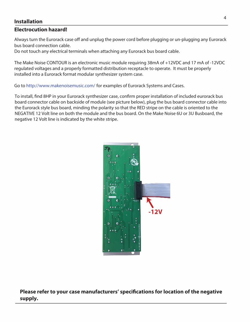
-12V
Installation
To install, �nd 8HP in your Eurorack synthesizer case, con�rm proper installation of included eurorack busboard connector cable on backside of module (see picture below), plug the bus board connector cable intothe Eurorack style bus board, minding the polarity so that the RED stripe on the cable is oriented to the NEGATIVE 12 Volt line on both the module and the bus board. On the Make Noise 6U or 3U Busboard, the negative 12 Volt line is indicated by the white stripe.
Always turn the Eurorack case o� and unplug the power cord before plugging or un-plugging any Eurorack
5Overview
CONTOUR is a 4 Stage function generator derived from our 0-COAST synthesizer. It is designed to create Control Voltages to drive the DynaMix, modDemix, and other fast VCAs, VCFs, and more. The Contour takes inspiration from the original Loudness Contour circuit of the MiniMoog, which is perhaps the most well-known and heavily-used example of East Coast Synthesis. When patched to drive a VCA, the resulting amplitude Envelopes are more complex than that of our MATHS/Optomix combination. The Optomix, when used with an ADSR, slews the 4 stages of the ADSR function into fewer, distinct stages (hence the pairing of the MATHS or FUNCTION two stage Function Generators with Vactrol based circuits like Optomix). A faster VCA or Filter, such as our DynaMix or modDemix, articulates all four stages which sounds quite di�erent from the character of the MATHS/Optomix combination.
While most ADSR or 4-Stage Function Generators have 4 control parameters to de�ne the Attack, Decay, Sustain, and Release, the CONTOUR module makes use of the simpli�ed, but highly-functional arrangement found on the original MiniMoog Loudness Contour circuit, where the Decay parameter also sets the Release time. This simpli�ed arrangement makes the Contour faster to set-up and adjust. It also creates room to add a very useful parameter not found not the Minimoog Loudness Contour Circuit: Vari-Response. This parameter allows for shaping the resulting envelope from Linear to Exponential. Since the MiniMoog utilized an exponential VCA, the Loudness Contour circuit creates a Linear envelope control signal, thus allowing the VCA to shape it to the desired exponential response. Within the Modular synthesizer system, we are not certain what you will patch this Contour module to, and so we allow you to shape the control signal response as you see �t.

6Panel Controls
1. Gate Input: Gate applied to this input initiates the circuit. The result being a 0V to 8V function, aka Envelope. Range 1.5V or greater with Gate Width determining Sustain Time. 2. Onset Panel Control: Sets the time it takes for the Voltage Function to ramp up to maximum level. CW rotationincreases Onset Time. 3. Onset CV Input: Linear control signal input for the Onset parameter. Positive Control signals increase OnsetTime. Negative control signals decrease Onset Time with respect to the Onset Panel Control setting. 4. Sustain Panel Control: Sets the Voltage level the function Decays to and holds for the duration the Gate is High. Settings greater than 3:00 put Sustain into overdrive allowing for increasesd 10V maximum level. For 4-Stage ADSR type control signal set CCW of 3:00. 5. Decay Panel Control: Sets the time it takes for the Voltage function to ramp down to the Sustain stage and complete the Release stage. CW rotation increases Decay and Release Time. 6. Decay CV Input: Linear control signal input for Decay parameter. Positive control signals increase Decay and Release Times. Negative control signals decrease Decay and Release Times with respect to the Decay Panel Control.
7. Vari-Response Panel Control: Sets the response curve of the Contour function. Response is continuously variable from Linear to Exponential.
8. End of Onset (EON) / End of Contour (EOC) LED: Indicates the states of the EON and EOC outputs. When <Red>, EON is High and EOC is Low. When <Green>, EON is Low and EOC is High. 9. End of Onset (EON) Output: Gate Output that goes High at the end of the Onset portion of the function. 0V or 10V. 10. End of Contour (EOC) Output: Gate Output that goes High at the end of the Contour. 0V or 10V. 11. Mirrored LED: Indicates activity at the Mirrored Contour Output.
12. Mirrored Contour Output: Upside down/inverted version of the Contour signal. When Contour Output is at maximum, this output is at minimum and vice versa. Bu�ered, capable of driving a 4-way multiple. Typically 0-8V, but Sustain Overdrive allows it to reach up to 10V pp and thus fall below 0V.
13. Contour LED: Indicates activity at the Contour Output. 14. Contour Output: CV signal from the Contour circuit. Bu�ered and capable of accurately driving a 4 way Multiple. Typically, 8V peak to peak, but Sustain Overdrive allows it to reach up to 10V pp.
3
5
9
10
11 12 14
12
4
7
13
6
8
7Getting Started
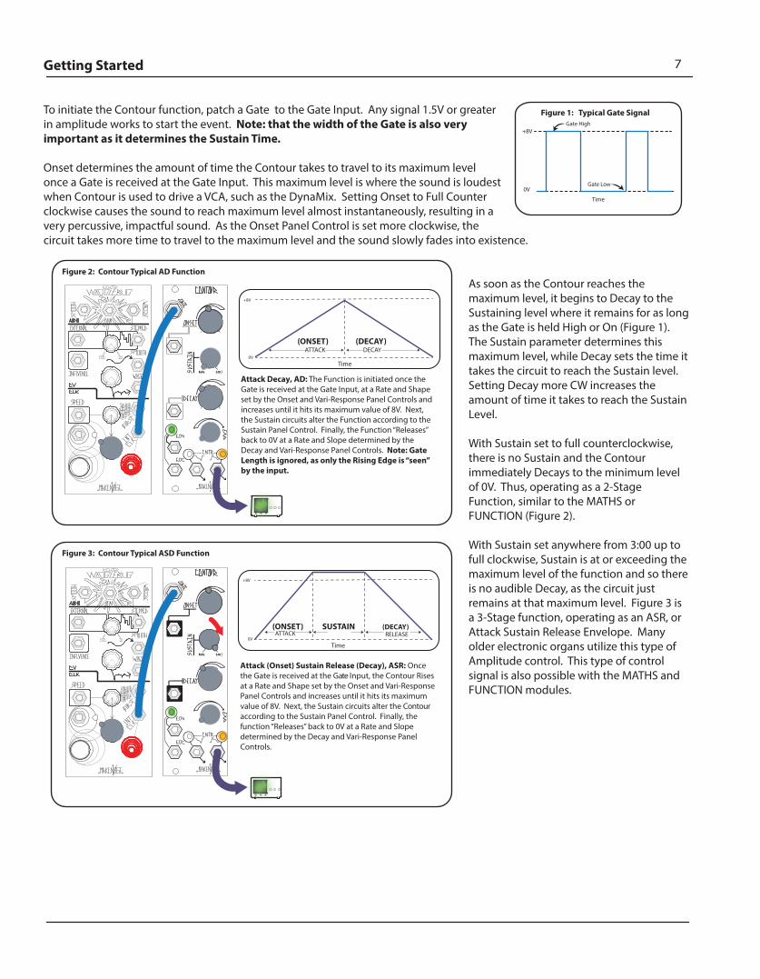
To initiate the Contour function, patch a Gate to the Gate Input. Any signal 1.5V or greater in amplitude works to start the event. Note: that the width of the Gate is also very important as it determines the Sustain Time.
Onset determines the amount of time the Contour takes to travel to its maximum level once a Gate is received at the Gate Input. This maximum level is where the sound is loudest when Contour is used to drive a VCA, such as the DynaMix. Setting Onset to Full Counter clockwise causes the sound to reach maximum level almost instantaneously, resulting in a very percussive, impactful sound. As the Onset Panel Control is set more clockwise, the circuit takes more time to travel to the maximum level and the sound slowly fades into existence.
As soon as the Contour reaches the maximum level, it begins to Decay to the Sustaining level where it remains for as long as the Gate is held High or On (Figure 1). The Sustain parameter determines this maximum level, while Decay sets the time it takes the circuit to reach the Sustain level. Setting Decay more CW increases the amount of time it takes to reach the Sustain Level.
With Sustain set to full counterclockwise, there is no Sustain and the Contour immediately Decays to the minimum level of 0V. Thus, operating as a 2-Stage Function, similar to the MATHS or FUNCTION (Figure 2).
With Sustain set anywhere from 3:00 up to full clockwise, Sustain is at or exceeding the maximum level of the function and so there is no audible Decay, as the circuit just remains at that maximum level. Figure 3 is a 3-Stage function, operating as an ASR, or Attack Sustain Release Envelope. Many older electronic organs utilize this type of Amplitude control. This type of control signal is also possible with the MATHS and FUNCTION modules.
+8V
0V
Gate High
Gate Low
Figure 1: Typical Gate Signal
Time
Figure 2: Contour Typical AD Function
+8V
0V
ATTACK DECAY
Time
(ONSET) (DECAY)
Attack Decay, AD: The Function is initiated once the Gate is received at the Gate Input, at a Rate and Shape set by the Onset and Vari-Response Panel Controls and increases until it hits its maximum value of 8V. Next, the Sustain circuits alter the Function according to the Sustain Panel Control. Finally, the Function “Releases” back to 0V at a Rate and Slope determined by the Decay and Vari-Response Panel Controls. Note: Gate Length is ignored, as only the Rising Edge is “seen” by the input.
Figure 3: Contour Typical ASD Function
+8V
0V
Time
Attack (Onset) Sustain Release (Decay), ASR: Once the Gate is received at the Gate Input, the Contour Rises at a Rate and Shape set by the Onset and Vari-Response Panel Controls and increases until it hits its maximum value of 8V. Next, the Sustain circuits alter the Contour according to the Sustain Panel Control. Finally, the function “Releases” back to 0V at a Rate and Slope determined by the Decay and Vari-Response Panel Controls.
(ONSET)ATTACK
(DECAY)RELEASE
SUSTAIN
8Getting Started (cont’d)
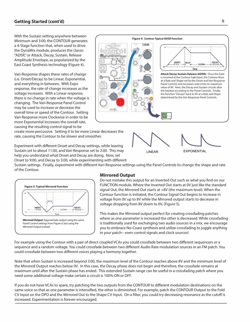
With the Sustain setting anywhere between Minimum and 3:00, the CONTOUR generates a 4-Stage function that, when used to drive the DynaMix module, produces the classic “ADSR,” or Attack, Decay, Sustain, Release Amplitude Envelope, as popularized by the East Coast Synthesis technology (Figure 4).
Vari-Response shapes these rates of change (i.e. Onset/Decay) to be Linear, Exponential, and everything in between. With Expo response, the rate of change increases as the voltage increases. With a Linear response, there is no change in rate when the voltage is changing. The Vari-Response Panel Control may be used to increase or decrease the overall time or speed of the Contour. Setting Vari-Response more Clockwise in order to be more Exponential increases the overall rate, causing the resulting control signal to be create more percussive. Setting it to be more Linear decreases the rate, causing the Contour to be slower and smoother.
Experiment with di�erent Onset and Decay settings, while leaving Sustain set to about 11:00, and Vari-Response set to 2:00. This may help you understand what Onset and Decay are doing. Now, set Onset to 9:00, and Decay to 3:00, while experimenting with di�erent Sustain settings. Finally, experiment with di�erent Vari-Response settings using the Panel Controls to change the shape and rate of the Contour.
Mirrored OutputDo not mistake this output for an Inverted Out such as what you �nd on our FUNCTION module. Where the Inverted Out starts at 0V just like the standard signal Out, the Mirrored Out starts at +8V (the maximum level). When the Contour function is initiated, the Contour Signal Out begins to increase in voltage from 0V up to 8V while the Mirrored output starts to decrease in voltage dropping from 8V down to 0V, (Figure 5).
This makes the Mirrored output perfect for creating crossfading patches where as one parameter is increased the other is decreased. While crossfading is traditionally used for exchanging two audio sources in a mix, we encourage you to embrace No-Coast synthesis and utilize crossfading to juggle anything in your patch-- even control signals and clock sources!
For example using the Contour with a pair of direct coupled VCAs you could crossfade between two di�erent sequencers or a sequence and a random voltage. You could crossfade between two di�erent Audio Rate modulation sources in an FM patch. You could crossfade between two di�erent voices playing a harmony together.
Note that when Sustain is increased beyond 3:00, the maximum level of the Contour reaches above 8V and the minimum level of the Mirrored Output reaches below 0V. In this case, the Decay phase does not begin and therefore, the crossfade remains at maximum until after the Sustain phase has ended. This extended Sustain range can be useful in a crossfading patch where you need some additional voltage make certain a circuit is 100% ON or OFF.
If you do not have VCAs to spare, try patching the two outputs from the CONTOUR to di�erent modulation destinations on the same voice so that as one parameter is intensi�ed, the other is diminished. For example, patch the CONTOUR Output to the Fold CV Input on the DPO and the Mirrored Out to the Shape CV Input. On a �lter, you could try decreasing resonance as the cuto� is increased. Experimentation is forever encouraged.
Figure 4: Contour Typical ADSR Function
+8V
0V
Time
Attack Decay Sustain Release (ADSR): Once the Gate is received at the Contour Gate Input, the Contour Rises at a Rate and Shape set by the Onset and Vari-Response Panel Controls and increases until it hits its maximum value of 8V. Next, the Decay and Sustain circuits alter the function according to the Panel Controls. Finally, the function “Decays” back to 0V at a Rate and Slope determined by the Vari-Response Panel Controls.
ATTACK RELEASEDECAY
SUSTAIN(ONSET) (DECAY)
EXPONENTIAL LINEAR
+8V
0V
Time
0V
Time
DECAYSUSTAIN
0V
Time
Mirrored Output: Approximate output using the same Panel Control settings from Figure 4, but using the Mirrored Output instead.
ATTACK RELEASE
DECAY
SUSTAIN(ONSET) (DECAY)
Figure 5: Typical Mirrored Function
9EON and EOC
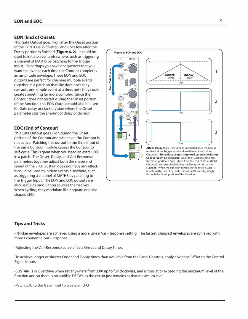
EON (End of Onset): This Gate Output goes High after the Onset portion of the CONTOUR is �nished, and goes low after the Decay portion is �nished (Figure 6, 2). It could be used to initiate events elsewhere, such as triggering a channel of MATHS by patching to the Trigger Input. Or perhaps you have a sequencer that you want to advance each time the Contour completes an amplitude envelope. These EON and EOC outputs are perfect for chaining multiple events together in a patch so that like dominoes they cascade, one simple event at a time, until they could create something far more complex! Since the Contour does not restart during the Onset portion of the function, this EON Output could also be used for Gate delay or clock division where the Onset parameter sets the amount of delay or division.
EOC (End of Contour) This Gate Output goes High during the Onset portion of the Contour and whenever the Contour is not active. Patching this output to the Gate Input of the same Contour module causes the Contour to self-cycle. This is great when you need an extra LFO in a patch. The Onset, Decay, and Vari-Response parameters together adjust both the shape and speed of the LFO. Sustain does not have any e�ect. It could be used to initiate events elsewhere, such as triggering a channel of MATHS by patching to the Trigger Input. The EON and EOC outputs are also useful as modulation sources themselves. When cycling, they modulate like a square or pulse shaped LFO.
Tips and Tricks
- Thicker envelopes are achieved using a more Linear Vari-Response setting. The fastest, sharpest envelopes are achieved with more Exponential Vari-Response.
-Adjusting the Vari-Response curve a�ects Onset and Decay Times.
-To achieve longer or shorter Onset and Decay times than available from the Panel Controls, apply a Voltage O�set to the Control Signal Inputs.
-SUSTAIN is in Overdrive when set anywhere from 3:00 up to full clockwise, and is thus at or exceeding the maximum level of the function and so there is no audible DECAY, as the circuit just remains at that maximum level.
-Patch EOC to the Gate Input to create an LFO.
Figure 6: EON and EOC
+10V
0V
ATTACK DECAY
Time
(ONSET) (DECAY)
+10V
0V
Time
1
2
3
+10V
0V
Time
1
2
3
Attack Decay (AD): The Function is initiated once the Gate is received at the Trigger Input and available at the Contour Output (1). Note: Gate Length is ignored, as only the Rising Edge is “seen” by the input. When the Function completes the Onset portion, a Gate is �red from the End Of Onset (EON) Output (2) and stays High during the Decay portion of the Function. When the Function completes the cycle, a Gate is �red from the End of Cycle (EOC) Output (3) and stays High through the Onset portion of the Function.
From
Gat
e So
urce
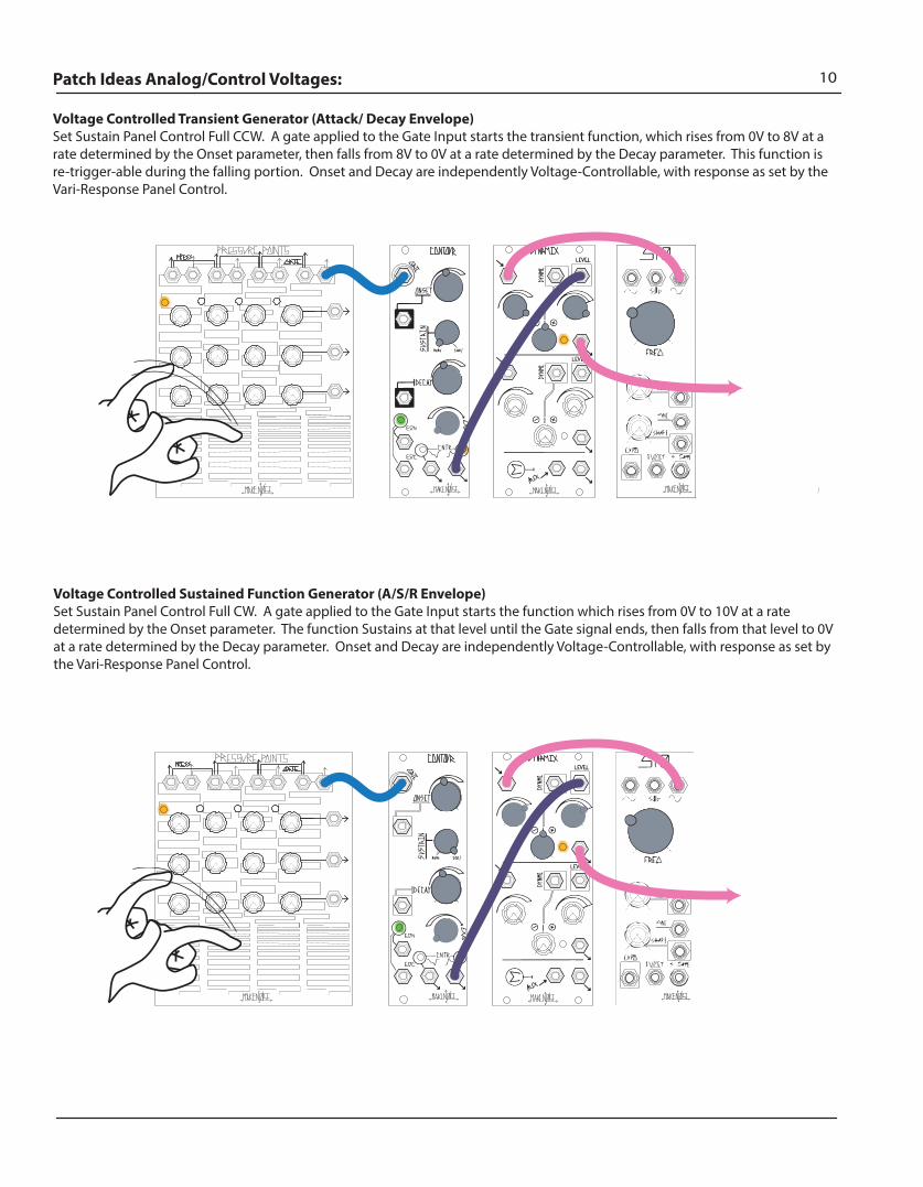
10Patch Ideas Analog/Control Voltages:
Voltage Controlled Transient Generator (Attack/ Decay Envelope) Set Sustain Panel Control Full CCW. A gate applied to the Gate Input starts the transient function, which rises from 0V to 8V at a rate determined by the Onset parameter, then falls from 8V to 0V at a rate determined by the Decay parameter. This function is re-trigger-able during the falling portion. Onset and Decay are independently Voltage-Controllable, with response as set by the Vari-Response Panel Control.
Voltage Controlled Sustained Function Generator (A/S/R Envelope) Set Sustain Panel Control Full CW. A gate applied to the Gate Input starts the function which rises from 0V to 10V at a rate determined by the Onset parameter. The function Sustains at that level until the Gate signal ends, then falls from that level to 0V at a rate determined by the Decay parameter. Onset and Decay are independently Voltage-Controllable, with response as set by the Vari-Response Panel Control.
11Patch Ideas (con’t)
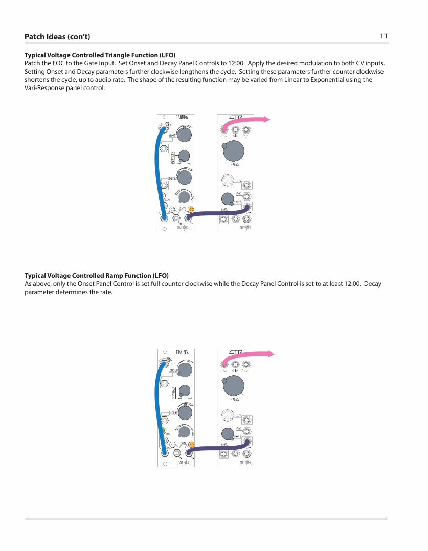
Typical Voltage Controlled Triangle Function (LFO) Patch the EOC to the Gate Input. Set Onset and Decay Panel Controls to 12:00. Apply the desired modulation to both CV inputs. Setting Onset and Decay parameters further clockwise lengthens the cycle. Setting these parameters further counter clockwise shortens the cycle, up to audio rate. The shape of the resulting function may be varied from Linear to Exponential using the Vari-Response panel control.
Typical Voltage Controlled Ramp Function (LFO) As above, only the Onset Panel Control is set full counter clockwise while the Decay Panel Control is set to at least 12:00. Decay parameter determines the rate.
12Patch Ideas Analog/Control Voltages:
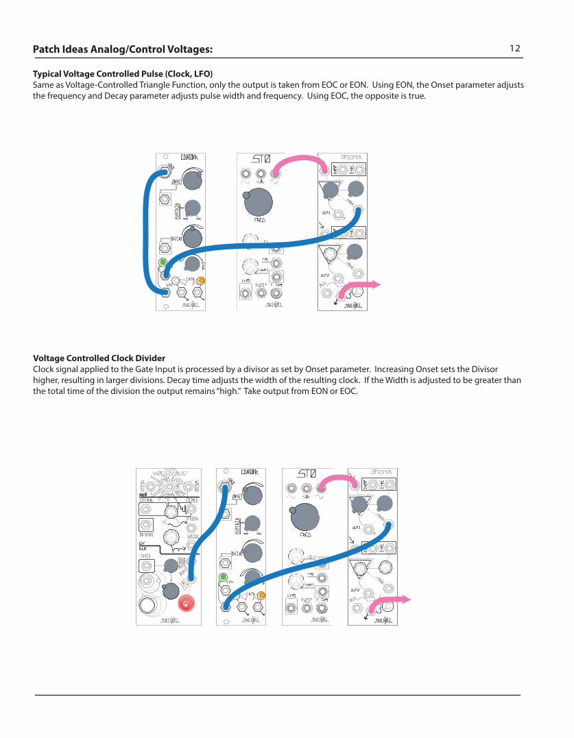
Typical Voltage Controlled Pulse (Clock, LFO)Same as Voltage-Controlled Triangle Function, only the output is taken from EOC or EON. Using EON, the Onset parameter adjusts the frequency and Decay parameter adjusts pulse width and frequency. Using EOC, the opposite is true.
Voltage Controlled Clock Divider Clock signal applied to the Gate Input is processed by a divisor as set by Onset parameter. Increasing Onset sets the Divisor higher, resulting in larger divisions. Decay time adjusts the width of the resulting clock. If the Width is adjusted to be greater than the total time of the division the output remains “high.” Take output from EON or EOC.

13Patch Ideas Analog/Control Voltages:
The New Vactrol Free Bongo:Set up a VCO for Two-Operator FM by applying a Sine wave to its Linear FM input or using the DPO’s FM Bus and patching the resulting waveform to DynaMix’s Signal Input. Set the associated attenuator to 4:00. Patch an Exponentially-shaped Envelope CV with a fast Rise or Onset and a slower Fall or Decay and no Sustain to the Level CV Input. Set the associated Level Combo Pot (attenuator) to 1:00. Trigger the envelope CV.
Gate Controlled CrossfaderUse this patch to fade between any two audio or CV sources, �ying at the speed of an envelope.
Variation: Gate controlled switchSet Onset and Decay full CCW, use EON and EOC instead of Contour and Mirrored Output.
Patch Ideas Analog/Control Voltages:
The New Vactrol Free Bongo:Set up a VCO for Two-Operator FM by applying a Sine wave to its Linear FM input or using the DPO’s FM Bus and patching the resulting waveform to DynaMix’s Signal Input. Set the associated attenuator to 4:00. Patch an Exponentially-shaped Envelope CV with a fast Rise or Onset and a slower Fall or Decay and no Sustain to the Level CV Input. Set the associated Level Combo Pot (attenuator) to 1:00. Trigger the envelope CV.
Gate Controlled CrossfaderUse this patch to fade between any two audio or CV sources, �ying at the speed of an envelope.
Variation: Gate controlled switchSet Onset and Decay full CCW, use EON and EOC instead of Contour and Mirrored Output.
14Patch Ideas Analog/Control Voltages:
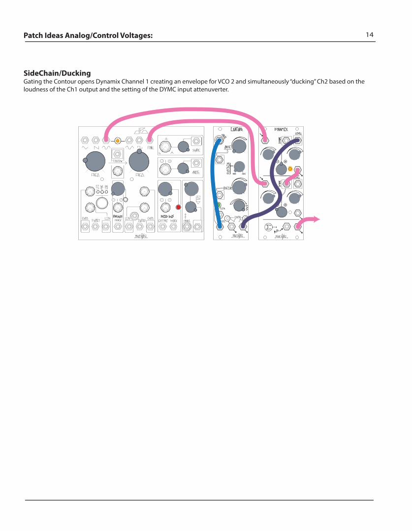
SideChain/DuckingGating the Contour opens Dynamix Channel 1 creating an envelope for VCO 2 and simultaneously “ducking” Ch2 based on the loudness of the Ch1 output and the setting of the DYMC input attenuverter.