#2 tab notcher
TRANSCRIPT

12430 55th St N · Oak Park Heights, MN 55082
Phone: 651.342.1756 · Fax: 651.342.1293
Email: [email protected]

© Copyright 2014 REV. 9-MAY-2014
2
SAFETY INFORMATION PG. 3
TECHNICAL DATA PG. 3
SET-UP PROCEDURE PG. 4-6
MAINTENANCE & BLADE SHARPENING PG. 7
#2 TAB NOTCHER BREAKDOWN AND PARTS LIST PG. 8-10
OPTIONAL STAND PG. 11
WARRANTY PG. 12
© Copyright 2014 REV. 9-MAY-2014
3
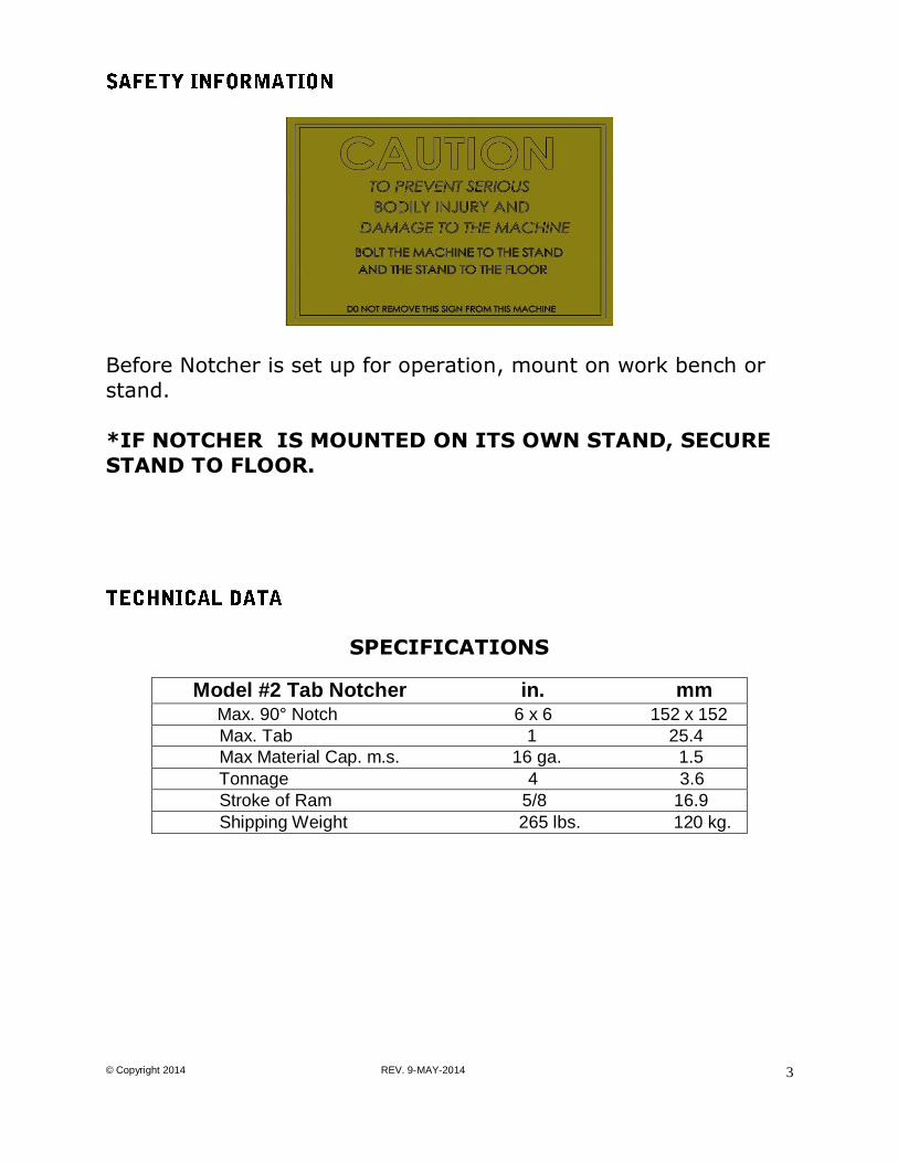
Before Notcher is set up for operation, mount on work bench or
stand.
*IF NOTCHER IS MOUNTED ON ITS OWN STAND, SECURE
STAND TO FLOOR.
SPECIFICATIONS
Model #2 Tab Notcher in. mm Max. 90° Notch 6 x 6 152 x 152
Max. Tab 1 25.4
Max Material Cap. m.s. 16 ga. 1.5
Tonnage 4 3.6
Stroke of Ram 5/8 16.9
Shipping Weight 265 lbs. 120 kg.

© Copyright 2014 REV. 9-MAY-2014
4
CHANGING SIZE OF TAB:
1. Loosen bolts (A) holding lower blade to blade carrier (DO NOT REMOVE). 2. Slide blades forward or back, holding them against shoulder machined in
blade carrier to obtain desired tab.
3. Tighten bolts (A).
4. Loosen bolts (B). 5. Lower ram until upper blades pass by lower blades (it may be necessary
to slide one upper blade back).
6. Slide blade (C) forward into notch in lower blade. Tighten bolts.
7. Slide blade (D) forward until it contacts blade (C). Tighten bolts. Note: A slight opening at (H) is normal to insure contact at cutting edge.

© Copyright 2014 REV. 9-MAY-2014
5
SETTING SIZE OF NOTCH:
1. Loosen screws (G) and set to required notch depth, reading scale along
edge (E).
Note: Scale is set to read from the edge of the notch so tab size must be
subtracted to obtain a corner notch of equal depth. 2. To notch along the side of a sheet, remove gauges and turn them upside
down. Screws will fit in outside slot when gauges are set parallel to each
other.
SHEARING LONG STRIPS FULL WIDTH:
Remove lower left blade and adjust right blade to maximum tab size.
SETTING DEPTH OF STROKE:
Adjust screw on cam until upper blade passes slightly by lower blade at
bottom of stroke.

© Copyright 2014 REV. 9-MAY-2014
6
ADJUSTING BLADE CLEARANCE:
1. Remove table.
2. Loosen blade mounting bolts (A) and (B).
3. Loosen blade carrier bolts (J). 4. Adjust lower blades to required tab (per instructions, B “changing size of
tab” 1, 2 and 3).
5. Set upper blades for no tab smaller than set in lower blades.
6. Back off screws (K) and pull blade carrier away from top blade. 7. Move ram to bottom of stroke.
8. Turn in screws (K) by hand pushing blade in until it contacts upper blade.
Placing a shim or piece of paper between blades will provide clearance to
prevent rubbing of blades. Too much clearance will cause a burr on work piece. Excessive rubbing of blade will reduce blade life.
9. Tighten bolts (J).
10. Set upper blade to tab notch in lower blade and tighten.
ADJUST RAM CLEARANCE:
1. Remove ram cap (M) and remove a shim from both sides. Color of shim indicates the thickness: Purple .0015; Red .002; Green .003; Blue .005.
2. Replace cap (M).
© Copyright 2014 REV. 9-MAY-2014
7
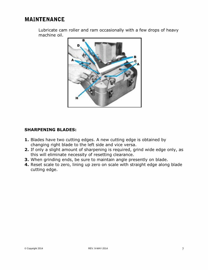
Lubricate cam roller and ram occasionally with a few drops of heavy
machine oil.
SHARPENING BLADES:
1. Blades have two cutting edges. A new cutting edge is obtained by
changing right blade to the left side and vice versa. 2. If only a slight amount of sharpening is required, grind wide edge only, as
this will eliminate necessity of resetting clearance.
3. When grinding ends, be sure to maintain angle presently on blade.
4. Reset scale to zero, lining up zero on scale with straight edge along blade cutting edge.

© Copyright 2014 REV. 9-MAY-2014
8

© Copyright 2014 REV. 9-MAY-2014
9
ITEM PART NUMBER DESCRIPTION QTY
1 8905350-000 T-NUT 4
2 8031110-101 BLADE CARRIER 1
3 21A0308C1102 SCREW-HHCS 3/8-16X1-1/2 4
4 61X0308 WASHER-3/8 4
4A 0102WILLIAMS WASHER WASHER-1/2 WILLIAMS (NOT SHOWN GOES UNDER 3/8 WASHER)
4
5 8031160-101 RULE 2
6 20C0104C0508 SCREW-FHSCS 1/4-20X5/8 3
7 8000110-501 TABLE 1
8 8031140-571 PROTRACTOR GAUGE-LH 1
8 8031140-572 PROTRACTOR GAUGE-RH 1
9 20B0X06C0108 SCREW-BHSCS #6-32X1/8 4
10 21A0104C0308 SCREW-HHCS 1/4-20X3/8 4
11 61X0104 WASHER-FLAT 1/4 4
12 8031120-901 LOWER BLADE 2
13 20C0516C2000 SCREW-FHSCS 5/16-18X2 4
14 8031120-900 UPPER BLADE 2
15 8031121-300 RAM WELDMENT 1
16 21A0516C1308 SCREW-HHCS 5/16-18X1-3/8 4
17 61X0516 WASHER-FLAT 5/16 4
18 20A0516C1102 SCREW-SHCS 5/16-18X1-1/2 4
19 8031110-609 GUARD WLDMT 1
20 21A0516C0102 SCREW-HHCS 5/16-18X1/2 4
21 61X0516 WASHER-FLAT 5/16 4
22 18A0516X1102 PIN-DOWEL 5/16X1-1/2 4
23 8040110-800 CAP 1
24 8690100-200 DRIVE FITTING 1
25 8470510-100 RETAINING RING 4
26 8060120-300 CAM ROLLER PIN 1
27 20B0516C0508 SCREW-BHSCS 5/16-18X5/8 1
28 8030120-800 LONG HANDLE ARM 1
29 8030120-302 CAM PIN 1
30 23C0516C2000 SCREW-SQHSS 5/16-18X2 1
31 31X0516C NUT-JAM 5/16-18 1
32 8156111-300 ROLLER 1
33 8030120-200 CAM 1
34 8310410-100 BEARING 1

© Copyright 2014 REV. 9-MAY-2014
10
ITEM PART NUMBER DESCRIPTION QTY
35 8030570-101 SHIM .0015” - PURPLE VARIES
36 8930570-101 SHIM .0020” - RED VARIES
37 8940570-101 SHIM .0030” - GREEN VARIES
38 8030570-102 SHIM .0050” - BLUE VARIES
39 8040110-200 UPPER CASTING 1
40 20A0102C1304 SCREW-SHCS 1/2-13X1-3/4 4
42 8150650-110 NAMEPLATE 1
45 030-6503001 CAUTION TAG 1
47 8031110-100 BASE 1
48 21A0308C1000 SCREW-HHCS 3/8-16X1 4
49 31X0308C NUT-JAM 3/8-16 4
50 031-1105011 BACKUP PLATE 4
51 21A0308C1104 SCREW-HHCS 3/8-16X1-1/4 4
52 19A0108X0102 PIN-DOWEL 1/8X1/2 4
53 8030120-801 HANDLE GRIP 1
8030650-301 LABEL – PINCH POINT (NOT SHOWN) 1

© Copyright 2014 REV. 9-MAY-2014
11
Part Number: 8031110-900
Stand Dimensions: 28” WIDE, 15” DEEP, 33-1/4” HIGH
Fasteners needed to attach Punch to the stand are the following:
(Fasteners to attach stand to floor are not included.)
PART NUMBER DESCRIPTION QTY
21A0102C2102 SCREW-HHCS 1/2-13X2-1/2 4
61X0102 WASHER-FLAT 1/2 4
30X0102C NUT-FULL 1/2-13 4

© Copyright 2014 REV. 9-MAY-2014
12
Defective parts, of a product manufactured by DI-ACRO, will be replaced or repaired at no charge for twelve (12) months following delivery to the original purchaser. Labor is included for the first 90 days. This warranty becomes void when products have not been used according to instructions furnished by DI-ACRO, nor does it cover any altered parts or unauthorized repairs. We cannot be responsible for the cost of repairs made or attempted outside of our factory. All other warranty claims are made FOB our plant, providing such items(s) is returned freight prepaid to our plant for examination. This warranty does not apply to parts, components or systems not manufactured by DI-ACRO. These products are covered instead by the existing warranties, if any, of their manufacturers. Normal service items with a reasonable life expectancy of less than one year are warranted only to the extent of the reasonable life under normal use and service. Authorization must be obtained from DI-ACRO before returning parts or equipment to the factory. DI-ACRO will satisfy this warranty by replacing the product or refunding the purchase price upon receipt, inspection and defect identification. DI-ACRO’s liability under this warranty shall not exceed the amount paid for the product. THIS IS DI-ACRO’S SOLE WARRANTY IN LIEU OF ALL OTHER WARRANTIES, EXPRESS OR IMPLIED, WHICH ARE HEREBY EXCLUDED, INCLUDING IN PARTICULAR ALL WARRANTIES OF MERCHANTABILITY, FITNESS OR ANY LOSS, DAMAGE OR EXPENSES DIRECTLY OR INDIRECTLY RELATED TO THE USE OF ITS PRODUCT OR FROM ANY OTHER CAUSE OR FOR CONSEQUENTIAL DAMAGES INCLUDING, WITHOUT LIMITATION, LOSS OF TIME AND LOSS OF PRODUCTION. IT IS EXPRESSLY UNDERSTOOD THAT DI-ACRO IS NOT RESPONSIBLE FOR DAMAGE OR INJURY CAUSED TO OTHER PRODUCTS, MACHINERY, PROPERTY OR PERSONS BY REASON OF THE USE OF ITS PRODUCTS.
12430 55th St N · Oak Park Heights, MN 55082
Phone: 651.342.1756 · Fax: 651.342.1293
Email: [email protected]