2 level guitar hero final report
TRANSCRIPT
MIDDLE EAST
TECHNICAL UNIVERSITYELECTRICAL AND ELECTRONICS
ENGINEERING DEPARTMENT
EE 314 DIGITAL ELECTRONICS LABORATORY
TERM PROJECT
2 LEVEL GUITAR HEROFINAL REPORT
CEM RECAİ ÇIRAK – 1674936
RAFAEL ASLANLI – 1526417

1. Introduction
In this project, the aim is to design a 2 level guitar hero game. There is two difficulty level in this
game. The first one is basic level and the second one is advanced level. In the first level, the aim of
the game is to push the button for only one note simultaneously. In the second level, more than one
of the notes should be pushed at the same time. In addition, there is a speed difference between
these two levels. Figure 1, shows the level descriptions.
Project is implemented with an FPGA board. Verilog is used as hardware description language.
Moreover, there is also a hardware part of the project which consists of four buttons for green, red,
yellow and blue notes. The output of the project is shown by colorful LEDs. For example, when red
button is pushed, red LED lights up if red note is caught on the screen. To obtain colorful images on
the computer monitor a VGA interface is used. Score of the game is changed depending on whether
true notes are caught or not. For example, when true notes are caught, score is increased while
Figure 1: Basic And Advanced Level Descriptions Of The Game
wrong buttons are pushed, score is decreased. There is also an audio output for each button
combination at different frequencies and a buzzer is used for this purpose.
2. FPGA (Field Programmable Gate Array)
Field Programmable Gate Arrays (FPGAs) are semiconductor devices that are based around a
matrix of configurable logic blocks (CLBs) connected via programmable interconnects. FPGAs can
be reprogrammed to desired application or functionality requirements after manufacturing. This
feature distinguishes FPGAs from Application Specific Integrated Circuits (ASICs), which are
custom manufactured for specific design tasks. Although one-time programmable (OTP) FPGAs are
available, the dominant types are SRAM based which can be reprogrammed as the design evolves.[1]
3. VGA (Video Graphics Array)
Video Graphics Array (VGA) is a widely used standard in video industry for the transmission of
video signals from a computer or microprocessor into a monitor or TV. Each 640x480 image is
called a frame and each frame contains 480 lines which are made up of 640 pixels. The monitor
starts displaying each frame by beginning from the first line and then the first pixel of this line. In
each line, the display order is from left to right and each frame is written in an order from top to
bottom. So, the first pixel is always at the top left corner, while the last pixel at the bottom right. To
generate an image buffer with at least 640x480 = 307200 bits to store each line and frame in order
to form a coherent image. However there is a need to adjust two synchronization signals called
HSync (Horizontal Synchronization) and VSync (Vertical Synchronization) in order to see a video.
These signals tell the monitor when a line or frame is finished, and the monitor should start from the
next line or frame. To send the color information to the monitor, a digital RGB data is supplied.[2]
4. HSync and Vsync:
HSync and VSync are necessary in order to tell the monitor to start or stop writing a line or frame.
It is needed to build the necessary digital blocks in order to correctly form these two signals. These
blocks are basically counters with some modifications. The horizontal and vertical synchronization
signals in Figure 2 with the corresponding timing in Table 1.

By observing Figure 2 and Table 1, it is understanded that the HSync signal is used to synchronize
one line in a frame, while VSync is used to synchronize each frame. Basically, when HSync or
VSync is low, the monitor understands that it needs to switch from one line or frame to the next.
Back and front porch are idle stages where the monitor is getting ready to write the next pixel or
line. They also include 8 pixel and line over scan or border pixels or lines outside of standard view
of the monitor.
The video input signals, RGB, of a VGA monitor should be off or black during H.Sync or V.Sync
stages, and front or back porch stages. The video input signals should only be active during an
active video transmission stage, which are highlighted in Figure 2.
Figure 2: HSync and VSync
Table 1: Timing

In order to construct these HSync and VSync signals and to achieve transmission of each line or
pixel, a 25 MHz clock signal is needed. This will also mean that each pixel will be transmitted at 25
MHz to the monitor during active video stages.
5. Implementation
In implementation part, as hardware description language, Verilog is used. Complete
implementation of the game consists of one module which is called "game" and nine subparts of
this module.
In the first part, game module is defined. All inputs and outputs of the module are specified. All
necessary wires and registers with proper sizes are defined. The first part of the code as follows:
//define modulemodule game(button, clock, level, h_sync, v_sync, red, green, blue, led_r, led_y, led_g, led_b, pfm);
//specifications of inputs and outputs and definitions of wires and registers
//define inputsinput[3:0] button;input clock;input level;
//define outputsoutput h_sync;output v_sync;output[2:0] red;output[2:0] green;output[1:0] blue;output led_r;output led_y;output led_g;output led_b;output pfm;
//define wireswire clock;wire[3:0] button;
//define registersreg level, clk, h_sync, v_sync, led_r, led_y, led_g, led_b, pfm, right_1, wrong_1, right_2, wrong_2, right_3, wrong_3, right_4, wrong_4;reg[1:0] clk_cnt, blue;reg[2:0] red, green;reg[3:0] beat, note, note_1, note_2, note_3, note_4, passed_1, passed_2, passed_3, passed_4, i, j, k_1, k_2, k_3, k_4, l_1, l_2, l_3, l_4;reg[5:0] bps_cnt;reg[7:0] score;reg[9:0] h_cnt, v_cnt, v_edge_1[15:0], v_edge_2[15:0], v_edge_3[15:0], v_edge_4[15:0];reg[19:0] f_cnt;
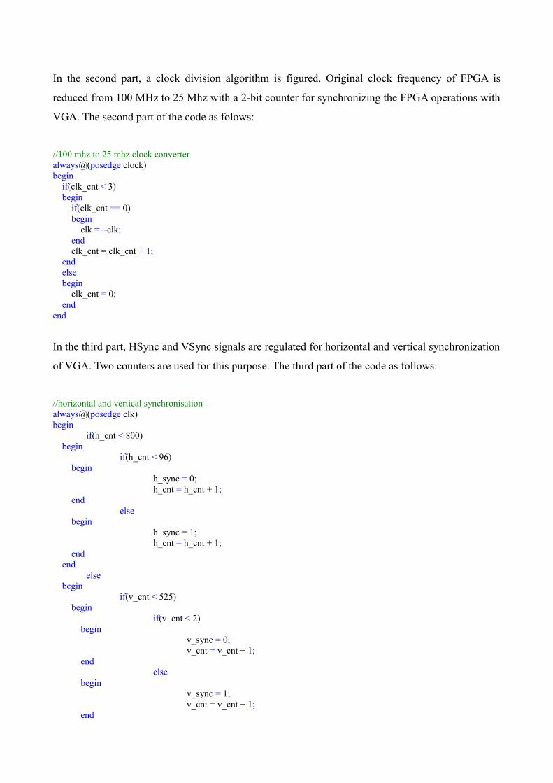
In the second part, a clock division algorithm is figured. Original clock frequency of FPGA is
reduced from 100 MHz to 25 Mhz with a 2-bit counter for synchronizing the FPGA operations with
VGA. The second part of the code as folows:
//100 mhz to 25 mhz clock converteralways@(posedge clock)begin if(clk_cnt < 3) begin if(clk_cnt == 0) begin clk = ~clk; end clk_cnt = clk_cnt + 1; end else begin clk_cnt = 0; endend
In the third part, HSync and VSync signals are regulated for horizontal and vertical synchronization
of VGA. Two counters are used for this purpose. The third part of the code as follows:
//horizontal and vertical synchronisationalways@(posedge clk)begin
if(h_cnt < 800) begin
if(h_cnt < 96) begin
h_sync = 0;h_cnt = h_cnt + 1;
endelse
beginh_sync = 1;h_cnt = h_cnt + 1;
end end
else begin
if(v_cnt < 525) begin
if(v_cnt < 2) begin
v_sync = 0;v_cnt = v_cnt + 1;
endelse
beginv_sync = 1;v_cnt = v_cnt + 1;
end
endelse
beginv_cnt = 0;
endh_cnt = 0;
endend
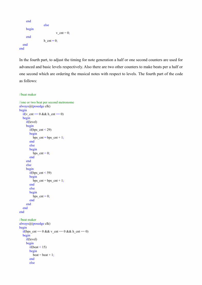
In the fourth part, to adjust the timing for note generation a half or one second counters are used for
advanced and basic levels respectively. Also there are two other counters to make beats per a half or
one second which are ordering the musical notes with respect to levels. The fourth part of the code
as follows:
//beat maker
//one or two beat per second metronomealways@(posedge clk)begin if(v_cnt == 0 && h_cnt == 0) begin if(level) begin if(bps_cnt < 29) begin bps_cnt = bps_cnt + 1; end else begin bps_cnt = 0; end end else begin if(bps_cnt < 59) begin bps_cnt = bps_cnt + 1; end else begin bps_cnt = 0; end end endend
//beat makeralways@(posedge clk)begin if(bps_cnt == 0 && v_cnt == 0 && h_cnt == 0) begin if(level) begin if(beat < 15) begin beat = beat + 1; end else

begin beat = 0; end end else begin if(beat < 7) begin beat = beat + 1; end else begin beat = 0; end end endend
In the fifth part, two readily prepared song compositions are defined. Notes is changed with each
new beat according to these song compositions. The fifth part of the code as follows:
//song compositonsalways@(posedge clk)begin if(note == 0) begin if(level) begin if(bps_cnt == 0 && v_cnt == 0 && h_cnt == 0) begin if(beat == 0) begin note = 5; end if(beat == 1) begin note = 6; end if(beat == 2) begin note = 9; end if(beat == 3) begin note = 4; end if(beat == 4) begin note = 12; end if(beat == 5) begin note = 8; end if(beat == 6) begin note = 13; end if(beat == 7)
begin note = 3; end if(beat == 8) begin note = 3; end if(beat == 9) begin note = 12; end if(beat == 10) begin note = 10; end if(beat == 11) begin note = 14; end if(beat == 12) begin note = 8; end if(beat == 13) begin note = 5; end if(beat == 14) begin note = 9; end if(beat == 15) begin note = 2; end end end else begin if(bps_cnt == 0 && v_cnt == 0 && h_cnt == 0) begin if(beat == 0) begin note = 1; end if(beat == 1) begin note = 4; end if(beat == 2) begin note = 1; end if(beat == 3) begin note = 8; end if(beat == 4) begin note = 1; end if(beat == 5) begin

note = 4; end if(beat == 6) begin note = 2; end if(beat == 7) begin note = 1; end end end endend
In sixth part, each new note is checked and and all existed notes are shifted down on the screen
There are four counters which are indicating the number of generated notes seperately for four
different notes. If a new note comes, relevant counter is increased. After that, vertical positions of
all notes which are existed but not performed yet are increased. So, this means all screen is shifted
down. The sixth part of the code as follows:
//shift down notes
//check if there is a new notealways@(posedge clk)begin //if a new note_1 comes if(note == 1 || note == 3 || note == 5 || note == 7 || note == 9 || note == 11 || note == 13 || note == 15) begin note = 0; note_1 = note_1 + 1; end //if a new note_2 comes if(note == 2 || note == 3 || note == 6 || note == 7 || note == 10 || note == 11 || note == 14 || note == 15) begin note = 0; note_2 = note_2 + 1; end //if a new note_3 comes if(note == 4 || note == 5 || note == 6 || note == 7 || note == 12 || note == 13 || note == 14 || note == 15) begin note = 0; note_3 = note_3 + 1; end //if a new note_4 comes if(note == 8 || note == 9 || note == 10 || note == 11 || note == 12 || note == 13 || note == 14 || note == 15) begin note = 0; note_4 = note_4 + 1; endend
//shift down all generated notes at each new frame
//shift note 1always@(posedge clk)begin if(k_1 <= note_1)

begin if(v_edge_1[k_1] < 526) begin if(level) begin v_edge_1[k_1] = v_edge_1[k_1] + 2 * (note_1 - passed_1); end else begin v_edge_1[k_1] = v_edge_1[k_1] + (note_1 - passed_1); end end else begin passed_1 = passed_1 + 1; end if(v_cnt == 0 && h_cnt ==0) begin if(k_1 < note_1) begin k_1 = k_1 + 1; end else begin k_1 = passed_1; end end endend
//shift note 2always@(posedge clk)begin if(k_2 <= note_2) begin if(v_edge_2[k_2] < 526) begin if(level) begin v_edge_2[k_2] = v_edge_2[k_2] + 2 * (note_2 - passed_2); end else begin v_edge_2[k_2] = v_edge_2[k_2] + (note_2 - passed_2); end end else begin passed_2 = passed_2 + 1; end if(v_cnt == 0 && h_cnt ==0) begin if(k_2 < note_2) begin k_2 = k_2 + 1; end else begin k_2 = passed_2; end end endend

//shift note 3always@(posedge clk)begin if(k_3 <= note_3) begin if(v_edge_3[k_3] < 526) begin if(level) begin v_edge_3[k_3] = v_edge_3[k_3] + 2 * (note_3 - passed_3); end else begin v_edge_3[k_3] = v_edge_3[k_3] + (note_3 - passed_3); end end else begin passed_3 = passed_3 + 1; end if(v_cnt == 0 && h_cnt ==0) begin if(k_3 < note_3) begin k_3 = k_3 + 1; end else begin k_3 = passed_3; end end endend
//shift note 4always@(posedge clk)begin if(k_4 <= note_4) begin if(v_edge_4[k_4] < 526) begin if(level) begin v_edge_4[k_4] = v_edge_4[k_4] + 2 * (note_4 - passed_4); end else begin v_edge_4[k_4] = v_edge_4[k_4] + (note_4 - passed_4); end end else begin passed_4 = passed_4 + 1; end if(v_cnt == 0 && h_cnt ==0) begin if(k_4 < note_4) begin k_4 = k_4 + 1; end else begin
k_4 = passed_4; end end endend
In seventh part, buttons are checked. If there is any pressed button, it is checked whether pressed
button or buttons corresponds to right note or notes or not. If right notes are caught, LEDs which are
representing those notes are lit up and also score is increased with respect to levels. If wrong
buttons are pressed, none of the LEDs are lit up and score is decreased with respect to levels. The
seventh part of the code as follows:
//light up leds and update score
//if button 1 is pressedalways@(posedge clk)begin if(button == 1 || button == 3 || button == 5 || button == 7 || button == 9 || button == 11 || button == 13 || button == 15) begin if(right_1 == 0 && wrong_1 == 0) begin for(j = 0; j < (note_1 - passed_1); j = j + 1) begin if(380 < v_edge_1[j] < 410) begin right_1 = 1; end end if(right_1) begin led_r = 1; end else begin wrong_1 = 1; end end end if(v_cnt == 0 && h_cnt == 0) begin if(right_1) begin if(level) begin if(score < 190) begin score = score + 10; end else begin score = 200; end end else begin if(score < 175) begin

score = score + 25; end else begin score = 200; end end end if(wrong_1) begin if(score > 10) begin score = score - 10; end else begin score = 0; end end end if(bps_cnt == 0 && v_cnt == 0 && h_cnt == 0) begin right_1 = 0; wrong_1 = 0; led_r = 0; endend
//if button 2 is pressedalways@(posedge clk)begin if(button == 2 || button == 3 || button == 6 || button == 7 || button == 10 || button == 11 || button == 14 || button == 15) begin if(right_2 == 0 && wrong_2 == 0) begin for(j = 0; j < (note_2 - passed_2); j = j + 1) begin if(380 < v_edge_2[j] < 410) begin right_2 = 1; end end if(right_2) begin led_y = 1; end else begin wrong_2 = 1; end end end if(v_cnt == 0 && h_cnt == 0) begin if(right_2) begin if(level) begin if(score < 190) begin score = score + 10; end else
begin score = 200; end end else begin if(score < 175) begin score = score + 25; end else begin score = 200; end end end if(wrong_2) begin if(score > 10) begin score = score - 10; end else begin score = 0; end end end if(bps_cnt == 0 && v_cnt == 0 && h_cnt == 0) begin right_2 = 0; wrong_2 = 0; led_y = 0; endend
//if button 3 is pressedalways@(posedge clk)begin if(button == 4 || button == 5 || button == 6 || button == 7 || button == 12 || button == 13 || button == 14 || button == 15) begin if(right_3 == 0 && wrong_3 == 0) begin for(j = 0; j < (note_3 - passed_3); j = j + 1) begin if(380 < v_edge_3[j] < 410) begin right_3 = 1; end end if(right_3) begin led_g = 1; end else begin wrong_3 = 1; end end end if(v_cnt == 0 && h_cnt == 0) begin if(right_3)

begin if(level) begin if(score < 190) begin score = score + 10; end else begin score = 200; end end else begin if(score < 175) begin score = score + 25; end else begin score = 200; end end end if(wrong_3) begin if(score > 10) begin score = score - 10; end else begin score = 0; end end end if(bps_cnt == 0 && v_cnt == 0 && h_cnt == 0) begin right_3 = 0; wrong_3 = 0; led_g = 0; endend
//if button 4 is pressedalways@(posedge clk)begin if(button == 8 || button == 9 || button == 10 || button == 11 || button == 12 || button == 13 || button == 14 || button == 15) begin if(right_4 == 0 && wrong_4 == 0) begin for(j = 0; j < (note_4 - passed_4); j = j + 1) begin if(380 < v_edge_4[j] < 410) begin right_4 = 1; end end if(right_4) begin led_b = 1; end
else begin wrong_4 = 1; end end end if(v_cnt == 0 && h_cnt == 0) begin if(right_4) begin if(level) begin if(score < 190) begin score = score + 10; end else begin score = 200; end end else begin if(score < 175) begin score = score + 25; end else begin score = 200; end end end if(wrong_4) begin if(score > 10) begin score = score - 10; end else begin score = 0; end end end if(bps_cnt == 0 && v_cnt == 0 && h_cnt == 0) begin right_4 = 0; wrong_4 = 0; led_b = 0; endend
In the eighth part, all images which are including vertical brackets, reference lines, score bar and
notes are drawn and displayed on the screen at each frame. Vertical brackets seperate the notes and
represents the guitar strings. Reference lines specify place which the player should perform the
notes between these lines. The eighth part of the code as follows:

//draw all screenalways@(posedge clk)begin //draw reference lines and vertical brackets if((((390 < v_cnt < 395) || (455 < v_cnt < 460)) && (200 < h_cnt < 625)) || (200 < h_cnt < 205) || (305 < h_cnt < 310)|| (410 < h_cnt < 415) || (515 < h_cnt < 520) || (620 < h_cnt < 625)) begin red = 7; green = 7; blue = 3; end
//draw note 1 for(l_1 = passed_1; l_1 <= note_1; l_1 = l_1 + 1) begin if((204 < h_cnt < 306) && (v_edge_1[l_1] < v_cnt < (v_edge_1[l_1] + 60))) begin if(35 < v_cnt < 516) begin red = 7; green = 0; blue = 0; end end end
//draw note 2 for(l_2 = passed_2; l_2 <= note_2; l_2 = l_2 + 1) begin if((309 < h_cnt < 411) && (v_edge_2[l_2] < v_cnt < (v_edge_2[l_2] + 60))) begin if(35 < v_cnt < 516) begin red = 7; green = 7; blue = 0; end end end
//draw note 3 for(l_3 = passed_3; l_3 <= note_3; l_3 = l_3 + 1) begin if((414 < h_cnt < 516) && (v_edge_3[l_3] < v_cnt < (v_edge_3[l_3] + 60))) begin if(35 < v_cnt < 516) begin red = 0; green = 7; blue = 0; end end end
//draw note 4 for(l_4 = passed_4; l_4 <= note_4; l_4 = l_4 + 1) begin if((519 < h_cnt < 621) && (v_edge_4[l_4] < v_cnt < (v_edge_4[l_4] + 60))) begin if(35 < v_cnt < 516) begin red = 0; green = 0;

blue = 3; end end end
//draw score bar if(((675 < h_cnt < 690) && ((375 - score) < v_cnt < 375)) || (((665 < h_cnt < 700))&&(375 < v_cnt < 380))) begin red = 0; green = 7; blue = 3; endend
In the ninth and the last part, a 1-bit register pfm represents the frequency modulated pulse signal.
This signal is sent to a buzzer. Frequency of signal is changed with respect to the combination of
pressed buttons. The ninth and the last part of the code as follows:
//audio output waveform generator
//change frequency with respect to button combinationalways@(posedge clk)begin if(button) begin if(button == 1) begin if(f_cnt < 213675) begin if(f_cnt == 0) begin pfm = ~pfm; end f_cnt = f_cnt + 1; end else begin f_cnt = 0; end end if(button == 2) begin if(f_cnt < 120192) begin if(f_cnt == 0) begin pfm = ~pfm; end f_cnt = f_cnt + 1; end else begin f_cnt = 0; end end if(button == 3) begin if(f_cnt < 179859) begin

if(f_cnt == 0) begin pfm = ~pfm; end f_cnt = f_cnt + 1; end else begin f_cnt = 0; end end if(button == 4) begin if(f_cnt < 90253) begin if(f_cnt == 0) begin pfm = ~pfm; end f_cnt = f_cnt + 1; end else begin f_cnt = 0; end end if(button == 5) begin if(f_cnt < 160256) begin if(f_cnt == 0) begin pfm = ~pfm; end f_cnt = f_cnt + 1; end else begin f_cnt = 0; end end if(button == 6) begin if(f_cnt < 107296) begin if(f_cnt == 0) begin pfm = ~pfm; end f_cnt = f_cnt + 1; end else begin f_cnt = 0; end end if(button == 7) begin if(f_cnt < 135135) begin if(f_cnt == 0) begin pfm = ~pfm;
end f_cnt = f_cnt + 1; end else begin f_cnt = 0; end end if(button == 8) begin if(f_cnt < 30084) begin if(f_cnt == 0) begin pfm = ~pfm; end f_cnt = f_cnt + 1; end else begin f_cnt = 0; end end if(button == 9) begin if(f_cnt < 60240) begin if(f_cnt == 0) begin pfm = ~pfm; end f_cnt = f_cnt + 1; end else begin f_cnt = 0; end end if(button == 10) begin if(f_cnt < 40193) begin if(f_cnt == 0) begin pfm = ~pfm; end f_cnt = f_cnt + 1; end else begin f_cnt = 0; end end if(button == 11) begin if(f_cnt < 80386) begin if(f_cnt == 0) begin pfm = ~pfm; end f_cnt = f_cnt + 1; end
else begin f_cnt = 0; end end if(button == 12) begin if(f_cnt < 33784) begin if(f_cnt == 0) begin pfm = ~pfm; end f_cnt = f_cnt + 1; end else begin f_cnt = 0; end end if(button == 13) begin if(f_cnt < 56054) begin if(f_cnt == 0) begin pfm = ~pfm; end f_cnt = f_cnt + 1; end else begin f_cnt = 0; end end if(button == 14) begin if(f_cnt < 45126) begin if(f_cnt == 0) begin pfm = ~pfm; end f_cnt = f_cnt + 1; end else begin f_cnt = 0; end end if(button == 15) begin if(f_cnt < 67568) begin if(f_cnt == 0) begin pfm = ~pfm; end f_cnt = f_cnt + 1; end else begin f_cnt = 0;
end end end else begin pfm = 0; endend
//endmoduleendmodule
6. Conclusion
By this game project, we have learned how to implement the code written in Verilog onto FPGA
board. We have also implemented a VGA controller in an FPGA to generate images on VGA
monitors. Actually our project did not go perfect because of some mistakes in Verilog code and
some other mistakes in Xilinx ISE Design program. However, we have there was not any problem
about FPGA and VGA part. We could succesfully load the code on an FPGA and get images on
monitor via VGA. Taking into consideration that this was a serious project during for undergraduate
level university education. It can be said that we were nearly succesfull at this project and we had
fun during writing and implementing the project.
7. References
[1] http://www.xilinx.com/training/fpga/fpga-field-programmable-gate-array.htm
[2] http://www.mems.eee.metu.edu.tr/courses/ee314/project2014.pdf