2° generation bioethanol the world’s largest demo plant
TRANSCRIPT

2° Generation Bioethanol
The world’s largest demo plant
ready to be transferred all over the world
A Handbook Part II
Lignocellulosic ethanol production plant by Biochemtex in Italy

2
Authors: Rita Mergner (Part I), Rainer Janssen (Part I), Dominik Rutz (Part I), Isabella de Bari (Part I - Chapter 4), Fabio Sissot (Part I - Chapter 3), David Chiaramonti (Part II), Arianna Giovannini (Part II), Stefania Pescarolo (Part II), Renato Nistri (Part II)
Editors: David Chiaramonti, Arianna Giovannini, Rainer Janssen, Rita Mergner ISBN: 3-936338-32-9 Published: © 2013 by WIP Renewable Energies, Munich, Germany Contact: WIP Renewable Energies, Sylvensteinstr. 2, 81369 Munich, Germany [email protected], Tel.: +49 89 720 12 731 www.wip-munich.de Website: www.biolyfe.eu Copyright: All rights reserved. No part of this book may be reproduced in any form
or by any means, in order to be used for commercial purposes, without permission in writing from the publisher. The authors do not guarantee the correctness and/or the completeness of the information and the data included or described in this handbook.
Acknowledgement: This handbook was elaborated in the framework of the BioLYFE project (Grant agreement No. TREN/FP7EN/239204), supported by the European Commission under the FP7 framework programme. The authors would like to thank the European Commission for the support of the BioLYFE project as well as the reviewers and BioLYFE partners for their contribution to the handbook.

3
Content
The BIOLYFE project........................................................................................................... 4
Preface ................................................................................................................................. 5
Part II 2° Generation Bioethanol ......................................................................................... 6
The world’s largest demo plant ready to be transferred all over the world
ARIANNA GIOVANNINI, DAVID CHIARAMONTI, STEFANIA PESCAROLO, RENANO NISTRI
1 Introduction .................................................................................................................. 6
2 Second Generation Bioethanol Technology (PROESATM) ......................................... 7
3 Why Lignocellulosic Biomass? ................................................................................... 9
4 Key areas of the process ............................................................................................10
4.1. Crescentino plant quick information ........................................................................12
5 Main sections of the Crescentino Demonstration Plant ...........................................15
5.1. Biomass storage and raw material handling ...........................................................16
5.2. Pretreatment Area ..................................................................................................19
5.3. Enzymatic Hydrolysis Area .....................................................................................24
5.4. Fermentation Area .................................................................................................28
5.5. Distillation Area ......................................................................................................33
6 Future Prospective ......................................................................................................38
Part I Overview on the lignocellulosic ethanol production .............................................41
1 Introduction
2 Components of lignocellulosic feedstock
3 Feedstock provision
4 Pretreatment technologies
5 Hydrolysis processes
6 Fermentation and process configurations
7 Downstream processing (DSP)
8 Demonstration projects
List of Figures ....................................................................................................................42
List of Tables ......................................................................................................................43
Glossary ..............................................................................................................................44
General conversion units ..................................................................................................51

4
The BIOLYFE project
The BIOLYFE project aims at improving critical steps of the second generation bioethanol production process and at demonstrating the whole supply chain, from feedstock sourcing via fuel production to product utilization. The main result of the project is the construction of an efficient second generation industrial demonstration unit with an annual output of about 40,000 tons of lignocellulosic bioethanol.
The project is developing technologies allowing an increased and economically viable utilization of the lignocellulosic feedstock for the production of second generation bioethanol. In order to achieve this objective, BIOLYFE project focuses on hydrolysis and fermentation steps. BIOLYFE started in January 2010 and lasts for 3 years. The proejct is co-funded by the European Commission in the 7th Framework Programme (Project No. FP7-239204).
Project consortium:
Biochemtex (Project coordinator)
Arianna Giovannini [[email protected]] David Chiaramonti (Science and Technology) [[email protected]]
WIP Renewable Energies, Germany
Rainer Janssen [[email protected]]
Rita Mergner [[email protected]]
Novozymes, Denmark
Lone Bækgaard [[email protected]]
ENEA, Italy
Isabella De Bari [[email protected]] Federico Liuzzi [[email protected]]
Lund University, Sweden
Gunnar Lidén [[email protected]]
Benny Palmqvist [[email protected]]
Agriconsulting, Italy
Fabio Sissot [[email protected]]
IUS, Germany
Walter Kretschmer [[email protected]]
IFEU, Germany
Guido Reinhardt [[email protected]]
ETA Florence, Italy
Stefano Capaccioli [[email protected]]

5
Preface
The EU goal to reduce CO2 emissions by 80-95% until 2050 compared to 1990 levels is a driving force for the decarbonisation of the transport sector and integration of new approaches into existing regulatory frameworks. In the Energy Roadmap 2050 (COM/2011/ 885), the European Commission identified different directions for developing a long-term European framework towards decarbonisation of the energy system and expressed the need to invest into new renewable energy technologies, including second generation biofuels. The CARS 21 High Level Group (Competitive Automotive Regulatory System for the 21 century) established by the European Commission has identified second generation biofuels as particularly promising and recommended giving a substantial support for their development.
The first European regulation on the promotion of the use of energy from renewable sources covering all areas of renewable energies is a milestone of renewable energy policy in Europe. The Renewable Energy Directive (RED, 2009/28/EC) lays down a mandatory 10% target for energy from renewable sources in transport until 2020, strengthening the role of biofuels in improving the security of transport fuels supply.
Transition towards second generation biofuels enables CO2 savings and is promoted by the EU RD&D (Research, Development & Demonstration) activities as well as different incentives stimulating the private sector in technology development. For example, the RED provides an incentive to stimulate the second generation biofuels market by double-counting contribution made by biofuels produced from wastes, residues and lignocellulosic material.
Lignocellulosic ethanol production is one of the most promising second generation biofuel technologies. Even though different conversion technologies are available on the market, there are still challenges to overcome before launching a large scale industrial production.
This publication provides an overview of the second generation bioethanol technology in terms of available feedstock, pretreatment technologies and production processes.
Standardised units and abbreviations, which are commonly used at European level, were applied. Details on conversion units are given at the end of the handbook. The decimal sign is a point, and the thousand separator is a comma.

6
Part II 2° Generation Bioethanol
The world’s largest demo plant ready to be transferred all over the world
ARIANNA GIOVANNINI, DAVID CHIARAMONTI, STEFANIA PESCAROLO, RENANO NISTRI
1 Introduction
The BIOLYFE project, supported by the EU Commission through the FP7 funds, aims at improving critical process steps and demonstrating the industrial-scale production of second generation bioethanol, covering the whole supply chain, from feedstock sourcing via fuel production to product utilisation.
In the framework of the project, the first industrial demonstration-scale plant in the world for the production of bioethanol from lignocellulosic biomass was engineered an constructed by Biochemtex SpA in Crescentino (VC, Italy) with a capacity of 40,000 tons per year, based on PROESATM technology, with a dry biomass input of about 180,000 T/y.
The plant is designed to produce bioethanol through hydrolysis and fermentation of cellulose and hemicellulose from lignocellulosic biomass (agricultural by-products or energy crops not suitable for food consumption).
The official inauguration of the plant was held on 9th October 2013 at the presence of the Italian Minister for Economic Development Flavio Zanonato, the local Italian Authorities, the Ghisolfi family and the CEO of Novozymes along with representatives of the partnership TPG and TPG Biotech. The Crescentino bio-refinery is situated in a territory whose strong agricultural location allows exploiting varieties of biomass that are available at low cost within a 70 km range from the plant (principally rice and wheat straw). The company is also developing a dedicated production line fuelled by giant cane (Arundo donax) which can be cultivated without affecting agricultural food production.
One of the key points of the second generation ethanol plant in Crescentino is the complete integration of the value chain from feedstock to the final product that makes the process innovative. For this reason, a complete chain was created starting with agronomic studies, continuing with whole process development, ethanol production and lignin utilization. Particular attention was dedicated to energy recovery issues, and all the possible exploitable streams are used to minimize the external energy requirements.
From a technological point of view, the development target was to design, construct and operate an energy efficient pretreatment process able to produce pretreated material that facilitates optimal enzymatic and microorganism activity. In particular, a large effort has been done from the Biochemtex R&D Center in order to limit the formation of degradation products that could inhibit enzyme and microorganism performance. Plant has been designed to guarantee flexible operation with different feedstock and to maximize ethanol yield.
The entire demonstration plant takes advantages of important results obtained with the efforts of the BIOLYFE partnership in particular for feedstock supply, enzymes development, hydrolysis and fermentation optimization processes and scale up innovation.
Biochemtex, as part of the Mossi Ghisolfi Group, has a significant history in process engineering in biofuels and related process technologies, spanning research, development, planning, design, construction and operation of such facilities. Since 2007, more than € 120 million have been invested into R&D activities (11 patent applications filed) in order to prove second generation bioethanol technology on continuous scale. Moreover, Biochemtex has a wide experience concerning scale-up activities, with a high number of successful practical

7
examples, also within the biofuels sector for 1st generation plants. The Crescentino bioethanol plant is a scale-up of the PROESATM technology developed in the Biochemtex R&D center of in Rivalta (AL), Italy.
Figure 1: Night view of Crescentino ethanol plant
2 Second Generation Bioethanol Technology (PROESATM)
Based on its biofuels engineering experience, Biochemtex has conducted a complimentary research in the bioethanol area for over five years. This research has included:
- An extensive agronomic project on energy crops to support downstream plant development
- Development of a patent-pending pretreatment process for cellulosic biomass
- Innovative process development for a second generation cellulosic process
The Biochemtex PROESATM technology highlights some peculiar aspects complementary also to the BIOLYFE project:
- Field experimentation and selection of best energy crops
- Continuous pretreatment process development and piloting
- Design of a high solid content enzymatic hydrolysis reactor includes efficient use of enzyme cocktails
- Development of lignocellulosic ethanol fermentation (including C5 sugar conversion)
- Process integration

8
Figure 2: Basic scheme of second generation bioethanol production
The main differences between a generic second generation process and the Biochemtex lignocellulosic-to-ethanol PROESATM technology are characterized by:
- An innovative proprietary physical pretreatment process
- C5 concentration and treatment
- New proprietary process for viscosity reduction and simultaneous saccharification and co-fermentation able to process high solid content pretreated material into beers with high ethanol content
- Use of novel high performance enzymes
- Co-fermentation of both pentoses (C5) and hexoses (C6) sugars into ethanol
- A high efficiency integrated ethanol distillation and dehydration system
- Efficient lignin separation and drying
- System integration
Some of these results were reached also thanks to the BIOLYFE partnership.

9
3 Why Lignocellulosic Biomass?
Figure 3: Field operations
Second generation ethanol, commonly known as cellulosic ethanol, is the result of a combination of operations where cellulosic feedstocks are converted into ethanol by the action of selected enzymes. Wheat straw, corn stover, rice straw are classified as waste feedstock (agricultural residues) that can be used for ethanol conversion, together with energy crops (grasses and woods) with a positive impact on land use. In fact, they do not damage agricultural activities since they do not request particular inputs or water requirements and they are not for human beings sustain.
The adoption of renewable sources like lignocellulosic biomass represents a key point for PROESATM technology. In fact, the possibility to use selected energy crops (like Arundo donax) in addition to agricultural (wheat straw, rice straw, etc.) and forestry (woody materials - hardwood, softwood) residues is related to the following considerations:
- Respect for environment
- No competition fuel vs. food
- Easy to insert into the traditional agronomic system and biomass market
One of the most interesting aspect of second generation bioethanol is the use of both energy crops and agricultural residues as feedstock. They represent the most attractive source for energy production.
The project considered central the need to conduct extensive agronomic research to select and characterize a set of energy crop species and has developed, through Biochemtex Agro and Agriconsulting, a methodology to evaluate the growing potential of feedstock according to the geographical area of interest based on agronomic modelling. To date this work has generated sufficient data to demonstrate the economic viability of growing these crops for

10
conversion to liquid transportation fuels on a commercial basis and has developed some of the specific data necessary for the development of the supply system to support provision of these crops in a commercial supply chain in a range of geographical areas.
4 Key areas of the process
The key process units of the PROESATM second generation ethanol demonstration plant are explained below with further details in the following description:
- Raw Material Handling
- Biomass pretreatment
- C5 stream treatment and inhibitor removing
- Enzymatic hydrolysis and viscosity reduction
- Fermentation
- MOs (Microorganism) propagation
- Beer column section
- Rectifier column section
- Ethanol dehydration section
- Lignin separation and storage
- Natural gas boilers section
- Cooling Water and Chilled Water
- Fresh and potable water, Demi water unit
- CIP (Clean in Place) system, utilities and chemicals storage
- Gas treatment
- Waste Water treatment
- Truck and rail denatured ethanol loading facilities
11
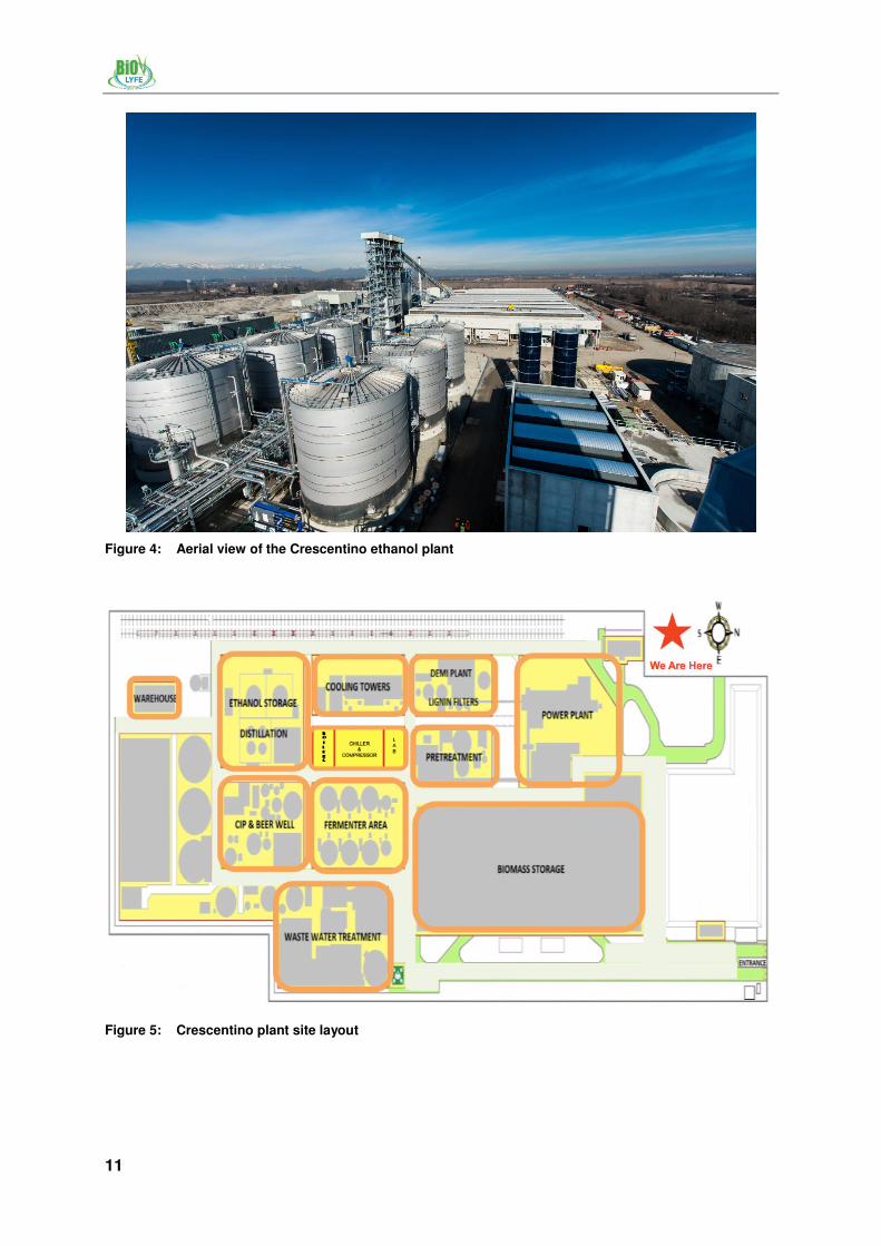
Figure 4: Aerial view of the Crescentino ethanol plant
Figure 5: Crescentino plant site layout
12
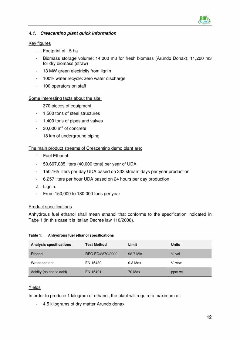
4.1. Crescentino plant quick information
Key figures
- Footprint of 15 ha
- Biomass storage volume: 14,000 m3 for fresh biomass (Arundo Donax); 11,200 m3 for dry biomass (straw)
- 13 MW green electricity from lignin
- 100% water recycle: zero water discharge
- 100 operators on staff
Some interesting facts about the site:
- 370 pieces of equipment
- 1,500 tons of steel structures
- 1,400 tons of pipes and valves
- 30,000 m3 of concrete
- 18 km of underground piping
The main product streams of Crescentino demo plant are:
1. Fuel Ethanol:
- 50,697,085 liters (40,000 tons) per year of UDA
- 150,165 liters per day UDA based on 333 stream days per year production
- 6,257 liters per hour UDA based on 24 hours per day production
2. Lignin:
- From 150,000 to 180,000 tons per year
Product specifications
Anhydrous fuel ethanol shall mean ethanol that conforms to the specification indicated in
Tabe 1 (in this case it is Italian Decree law 110/2008).
Table 1: Anhydrous fuel ethanol specifications
Analysis specifications Test Method Limit Units
Ethanol REG EC/2870/2000 98.7 Min. % vol
Water content EN 15489 0.3 Max % w/w
Acidity (as acetic acid) EN 15491 70 Max ppm wt.
Yields
In order to produce 1 kilogram of ethanol, the plant will require a maximum of:
- 4.5 kilograms of dry matter Arundo donax

13
- 4.4 kilograms of dry matter wheat straw
Construction time line
In April 2011, the Mayor of Crescentino town and the Ghisolfi family (Mr. Vittorio and Mr. Guido Ghisolfi in the photo) officially inaugurated the area dedicated to the construction of the plant.
Figure 6: Inauguration of the area dedicated to the construction
In the following months the intense activities began for the accomplishment of the Crescentino Biorefinery.

14
Figure 7: Construction timeline
Figure 8: Plant constructed at present day
NNNNoooovvvv 2 2 2 2000011112222 DeDeDeDec 2c 2c 2c 2000011112222
FFFFeeeebbbb 2 2 2 2000011112222 SSSSeeeepppptttt 2 2 2 2000011112222

15
Figure 9: Crescentino ethanol plant inauguration (October, 9th 2013)
5 Main sections of the Crescentino Demonstration Plant
Figure 10: Biomass storage

16
Figure 11: Biomass fed in the conveyor system
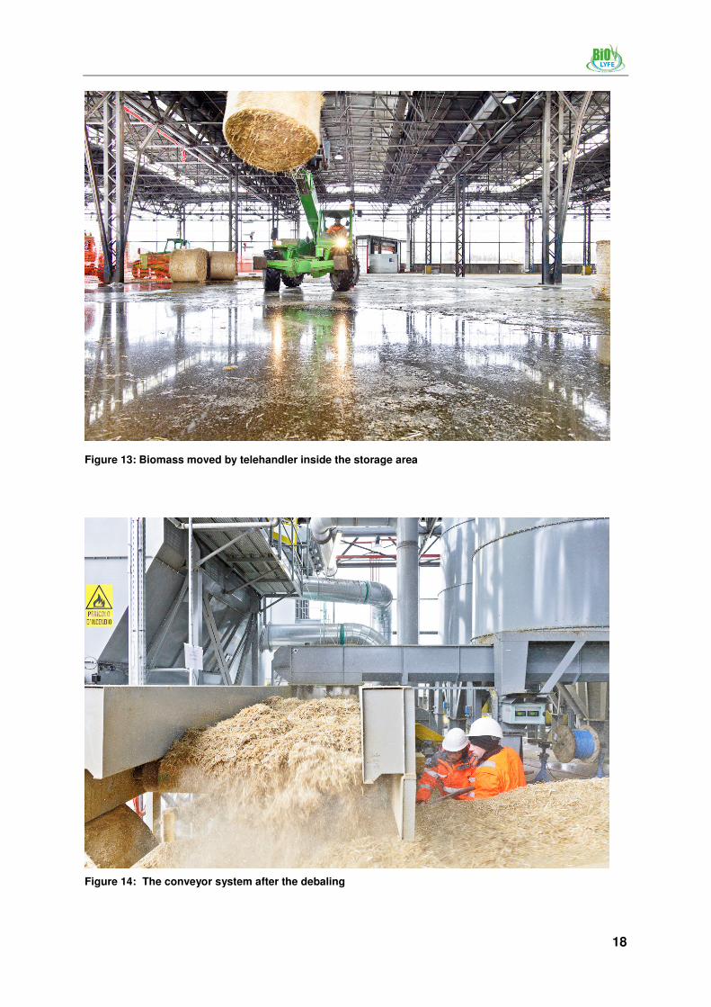
5.1. Biomass storage and raw material handling
The biomass normally fed to the plant, is stored in a warehouse and then transported with suitable conveying system to final grinding process before pretreatment.
The handling of biomass entering the plant depends on the type thereof: dry biomass (wheat straw) is used as buffer biomass when fresh biomass is not available; it is delivered as bales by truck, stored in open storage building and then transported with a bridge crane to a disassembling system where bales will be broken and screened for removal of metal, stones and other foreign materials before conveying into the final grinding process of pretreatment.
The operations necessary for the grinding and cleaning of the straw are carried out inside the storage facility, therefore is guaranteed the containment of dust and noise emissions from the site.
Fresh biomass storage
The fresh biomass (Arundo Donax) is stored in open storage building and then transported with suitable conveying system to process. Arundo Donax can be stored for three days from the time of collection on the ground in order to minimize degradation. Storage unit provides a storage volume of approximately wet 14,000 m3 equivalent to about 3 days production.

17
Figure 12: Arundo donax productive cycle from plowing to trasformation
Dry biomass storage and package
The dry biomass (wheat straw) is stored in piles in open storage building. Storage unit provides a storage volume of about dry 11,200 m3 equivalent to about 4 days of production. The storage volume is designed on the basis of an economic consideration. The entire movement within the building is operated by remote-controlled crane systems to minimize the presence of personnel inside the building.
Transfer to pretreatment process section includes the following steps:
- Conveyors to feed the surge bin
- The surge bin is located at elevation of about 45 to 50 m. The conveyors are pipe type
- Weighing system
- The flow rate of the final conveyor is controlled by a weighing system (weighted belt)
18
Figure 13: Biomass moved by telehandler inside the storage area
Figure 14: The conveyor system after the debaling

19
5.2. Pretreatment Area
Figure 15: Pretreatment area
Figure 16: The pretreatment area with the biomass feeding system

20
The main drivers in the choice of the pretreatment are the conservation of the sugars and the
accessibility of enzymes to the material that has passed through the pretreatment step. An
ideal process is able to guarantee complete access to the sugar during the subsequent
enzymatic hydrolysis step without degradation of the feedstock (and inhibitory compound
formation). In addition to the loss of sugar yield, inhibitory compounds, even in small quantity,
can represent an obstacle to the fermentation of the sugars by microorganisms and it is thus
necessary to orient the choice towards processes that do not produce high amounts of these
compounds.
For these reasons an innovative process has been developed and installed by Biochemtex in
Crescentino Demo Plant. The Biochemtex proprietary process cleaves the chemical bonds
between lignin, cellulose and hemicelluloses. The process has the advantages of high
efficiency on cellulose and hemicellulose free-up and no chemical addition and besides has
the capability to reduce the formation of inhibitors. The effective outcome in this step of the
process has the positive economical remark to make process and enzymes (the lowering in
the amount of enzyme used in the downstream operations) costs lower.
Means to achieve this result are:
- To reduce cellulose fiber crystallinity
- To increase material porosity and access to hydrolytic agents, even by depolymerization of the hemicellulose chains
The major advantages of the new pretreatment concept are:
- Easy to scale up
- No chemical addition: no special construction material required and neutralization operation
- High feedstock flexibility: possibility to treat worldwide crops such as energy crops, agricultural and industrial residues, woody species
- Able to process feedstock in a wide range of moisture content, size and density
- High C5 sugars recovery (with low inhibitors production) and enzymatic hydrolysis accessibility
- No need feedstock conditioning: no grinding, no size reduction other than primary bales shredding
The process is covered by several patents that refer to all the main advantages (high
recovery yields, high pretreated biomass accessibility). Indeed, also the C5 stream refining
section uses an enhanced system that allows removing undesired substances with
regenerative methods.
Design Basis
Care has been taken during the pretreatment step so that degradation or loss of carbohydrate is reduced and the formation of by-products inhibitory to the subsequent hydrolysis and fermentation processes, such as formic acid or furfural, is avoided or at least minimized1. Pretreatment can be a physical, chemical or biological transformation, although
1 Sun Y., and J. Cheng 2002. Hydrolysis of lignocellulosic materials for ethanol production: a review Bioresource
Technology 83: 1–11

21
in the majority of cases a combination of these is actually used. The table below2 provides a good overview of some pretreatment technologies and their main qualitative effects on the lignocellulosic material characteristics (se also Chapter 4 Handbook Part I).
Table 2: Qualitative effect of various pre-treatments on the biomass structure
After reviewing some of the most diffused pretreatment technologies, an investigation of the most promising technologies at bench and pilot scale has been done. Collected data and research activities have allowed Bichemtex to develop an innovative treatment that addresses some of the cost considerations of the generalized method. A pilot unit was used to investigate and develop metrics for raw material input, operative conditions (T, P, steam, flow rate and residence time), as well as pertinent physic-chemical phenomena. At the same time, modelling activities were carried out, with the aim to develop an instrument able to predict the system behaviour and to be used in the plant design work.
The analysis conducted on the scouting of different technologies at different levels, at conceptual level through literature and patent analysis and at techno-economical level through visits different potential technology provider (company and universities), highlighted steam explosion as the most promising process to reach the wanted scope.
Strengths of Biochemtex innovative pretreatment process is the high efficiency in cellulose
and hemicellulose release and no chemical addition, reducing the formation of inhibitors
(coming from sugar degradation, such as HMF and furfural, and acetic acid formed by
solubilization during the pretreatment reaction and related to the feedstock composition) and
the total energy consumption.
Figure 17 shows advantages of the Biochemtex pretreatment technology if compared with
mostly diffused processes in terms of glucan and xylan recovery and release of fermentable
sugars.
2 Mosier N., C. Wyman, B. Dale, R. Elander, Y.Y. Lee, M. Holtzapple, and M. Ladisch 2005. Features of promising
technologies for pretreatment of lignocellulosic biomass Bioresource Technology 96: 673–686

22
Figure 17: Advantages of Biochemtex proprietary technology
Biochemtex inhibitor removal
Biochemtex process is able to minimize the amount of by-products. It was considered useful
to explore existing technologies to assess the best results for their separation.
Figure 18: Compounds that could inhibit the microorganism activity
The acetic acid and other by-products go in the liquid fraction, so they can be easily
removed. Biochemtex has studied and developed a further integration process that foresees
the concentration and treatment of C5. In this step, C5 sugars obtained in a liquid stream
during pretreatment are concentrated and eventually refined. This process permit to increase
sugar (both monomeric and oligomeric form) concentration and to remove compounds, such
as acetic acid, furfural and 5-HMF, that can inhibit microorganism and have a negative effect
on downstream process.
With this aim, Biochemtex focused R&D activities to identify methods capable of removing
compounds potentially inhibiting the fermentation; also modeling work was used to simulate
the behavior of different biomass in different process conditions.
C5
Sugars Inhibitors
C6HMF
Furans Weak acids
Furfural
LEVULINIC ACID
FORMIC ACID
ACETIC ACID

23
Key unit operations in the Demo Plant
In order to complete the development of the complex technological process the Crescentino
Demo Plant has been constructed, representing the final test of advanced, novel and
integrated process concepts before technology commercialization.
Figure 19: The pretreatment area behind the fermenters
Figure 20: The pretreatment area

24
5.3. Enzymatic Hydrolysis Area
Figure 21: Pretreatment area
Figure 22: A frontal view of the area
Cellulose and hemicellulose hydrolysis represent a fundamental step in the ethanol production process, both from a technical and economic point of view. For this reason Biochemtex developed a proprietary hydrolysis technology at research center in Rivalta

25
Scrivia (Tortona, Italy) that is currently used in Crescentino demo plant. The goal reached, with extensive trials campaign, is an enzymatic hydrolysis of a high solid concentrated stream optimized for the demo plant. Furthermore, such experiments permitted to obtain a perfect integration of the hydrolysis step between pretreatment and fermentation units and consequently increase conversion process efficiencies and reduce investment costs. Indeed second generation ethanol production is a classic example that shows how process integration is a fundamental aspect and how the choice of the various pathways is determined by considering not only the single operation, but the whole package. In order to provide good overall process efficiencies with a lower capital investment, hydrolysis and fermentation steps have to be considered as they are an integrated single process.
Biochemtex has developed a proprietary viscosity reduction technology in order to most efficiently liquefy the pretreated material and to assure a constant and continuous flow of the material into the fermenter. The operation is processed through the enzyme action to a pumpable liquid which then undergoes a saccharification and fermentation process. A great achievement is the possibility to obtain liquefaction with very short residence time and also at dry matter content (up to 40%) not managed by traditional systems.
Figure 23: Block scheme of Crescentino viscosity reduction/enzymatic hydrolysis section
The first enzymatic liquefaction of complex cellulose and hemicellulose into simpler oligomers chains (C5 – C6) is performed with a very low energy consumption and reduced volume. A useful and practical aspect is that the system assures fully flexibility towards the possibility of changing the biotech components in case of further improvements using the same equipment.
The major advantages of the Crescentino viscosity reduction/enzymatic hydrolysis new concept are:
- Classic design that leads to an easily scale up activity
- Material is liquefied after few hours even at low enzymes load and at dry matter contents up to 40%
- Very low energy consumption for mixing due to the Biochemtex configuration
- Outlet stream is a pumpable liquid that can be easily sent to fermentation section
- Degree of hydrolysis is adjustable according to different requirements from other types of fermentation (i.e. sugars route to biochemical other than ethanol)
Design basis
Literature and patent analysis resulted that hydrolysis is strongly connected to the previous (pretreatment) and next (simultaneous saccharification and fermentation) stages. The first can provide material with different characteristics (in terms of moisture content, density,

26
fibers size), the latter requires a narrow range of fermentable sugar content. Over a certain limit value, yeast is inhibited and lower ethanol production is obtained. In order to be fermented, the material must be converted in a liquid that has to be depolymerized into simple sugars. A further complication is given by lignin that can obstacle liquefaction and adsorbs enzymes (sometimes in an irreversible way) lowering their activity.
The scouting of different hydrolysis technologies led to conclusion that enzymatic process holds several advantages:
- Efficiency is quite high and by-product production can be controlled
- Mild process conditions do not require expensive materials of construction
- Process energy requirements are relatively low
Figure 24: Mechanism for the enzymatic cellulose hydrolysis
Hydrolysis step purpose has a double function:
- Obtain a solution having a reasonable (depending also on fermentation process) sugar amount before fermentation that will be after converted to a beer, from which ethanol is extracted by distillation and eventually dehydration.
- Liquefy the solid content stream in order to guarantee a constant and continuous flow of the material into the fermenter.
Hydrolysis is carried out in more stages, the first of these is also called viscosity reduction
because the fed material, that has a solid appearance at the beginning, is liquefied during the
process thanks to the enzymes action on the cellulose chains.
The innovation of viscosity reduction in the Crescentino demo plant is to liquefy the pretreatment stream in a short time: this can improve the solid to liquid ratio.

27
Figure 25: Comparison between standard and new Chemtex technology
Enzyme Development
Efficient enzymes mixtures have a key role for the feasibility of bioethanol production from
lignocellulosics.
With a strong collaboration of Novozymes an enzyme mixture was developed and optimized
to fit the specific feedstock and the specific pre-treatment technology that will be adopted in
the demo plant.
Novozymes will supply the demo plant with a concentrate product called Cellic CTec 3 that is
globally available in commercial-scale quantities. Novozymes cocktail advantages are:
- High conversion yield
- Good performance at high solids content
- High tolerance to inhibitors
- Improved performance
- Reduced dosage
Key unit operations in the Demo Plant
Enzymatic hydrolysis Area
The treated C5 stream and the C6 stream are mixed together by a screw conveyor. The
mixture is fed to the enzymatic hydrolysis reactors to efficiently liquefy the pretreated
material.
Two reactors are disposed in series: the viscosity reduction tank, designed to work with a
high amount of dry matter (up to 40%). The retention time is set in order to decrease the
hydrolysate viscosity to a point that allows the transfer through a centrifugal gear pump. In
the second reactor the enzymatic hydrolysis goes on leading to simpler oligomeric chains
necessary for an efficient downstream conversion to ethanol. Configuration purpose is to
assure a constant and continuous hydrolysate flow into the fermenters.

28
Hydrolysis cooling system
The hydrolysis process temperature is set and controlled.
Vent gas treatment
Vent gas that is produced during hydrolysis is collected and routed to a VOC destroyer.
5.4. Fermentation Area
Figure 26: Fermentation area

29
Figure 27: Fermentation area
The fermentation process has to be tuned paying attention to the feedstock, the enzyme cocktail and the yeast strain used. In order to provide good overall process efficiencies with a lower capital investment, the fermentation process for second generation ethanol requires careful analysis in the design step. Basically there are two factors which must be taken into consideration that represent a challenge to bioethanol production on industrial scale. The first one is due to the fact that cellulose biomass contains two major sugars, glucose and xylose and microorganism are not eager to ferment the latter. Secondly, a number of inhibitor compounds are also present in the process stream, their composition and concentration depending on the hydrolysis and pre-treatment process used upstream.
An important factor for the cost-effective production of ethanol from lignocellulosic feedstocks is the high-yield, high-rate fermentation of biomass hydrolysates to ethanol. The demands on the microorganisms that perform this reaction are more complicated than those for conventional ethanol production from hexoses or their disaccharides, which uses exclusively Saccharomyces yeasts. For example, hydrolysis of hemicellulose generates substantial amounts of pentose (C5) sugars that can be fermented by only few strain of Saccharomyces cerevisiae.
Additionally, lignocellulosic hydrolysates contain numerous compounds that inhibit microbial growth, such as furfural and 5-hydroxymethyl furfural (HMF). Tolerance to these compounds, as well as to high concentrations of ethanol, is a prerequisite for efficient fermentation of biomass hydrolysates.
For this reason Biochemtex has spent many efforts to integrate hydrolysis and fermentation unit with the aim of maximize sugar conversion to ethanol. This intense research work done inside the Biolyfe project with the collaboration of University of LUND and the Italian ENEA lead to process design improvement that combine, in an innovative way, the steps involved. The strategy adopted in Crescentino demo plant can be described as a flexible hybrid process where occurs the simultaneous saccharification of both cellulose and hemicellulose and the co-fermentation of both glucose and pentose.

30
Figure 28: Block scheme of Crescentino fermentation section
The major advantages of the Crescentino fermentation process are:
- Fermentation of sugar to ethanol is a well know process and is comparable to first generation technology.
- Advantages over first generation: simultaneous co-fermentation of pentoses and hexoses:
o The co-fermentation allows carrying out the biological process in one reactor
o Increase the ethanol concentration in the fermentation broth
- Operating with standard equipment:
o Low investment cost for the reactors
o Low risk in the scale-up
Design Basis
Fermentation of sugar to ethanol is a well know process and can be carried out in a batch,
fed-batch or continuous mode. Typically, the process configuration chosen for big scale plant
can allow both operation in batch mode and continuous, with the first being normally
preferred to reduce the risk of losing a lot of intermediate product in case of contaminations.
The principal fermentation strategies are classified as follow:
- Separate Enzymatic Hydrolysis and Fermentation (SHF)
- Separate Enzymatic Hydrolysis and Co - Fermentation (SHCF)
- Simultaneous Saccharification and Fermentation (SSF)
- Simultaneous Saccharification and Co - Fermentation (SSCF)
In the fermentation section the research was focused in identifying microorganism able to
ferment both C5 and C6 sugars, with particular attention on glucose and xylose assimilation to
ethanol production. The common yeast Saccharomyces cerevisiae, is tolerant to inhibitory

31
compounds present in biomass hydrolysates, as well as high temperature, osmolarity, and
low pH.
Biochemtex bioethanol process utilizes SSCF (Simultaneous Hydrolysis & Co-Fermentation), which is a quite new process at industrial scale and combines both hydrolysis and fermentation. The main innovation in this case is represented by the possibility to co-ferment both glucose and pentose to ethanol in one reactor, this increase a lot the ethanol concentration in the fermentation broth. Moreover the operability with the standard equipment is considered an advantage due to:
- Low investment cost for the reactors
- Low risk in the scale-up
All the studies on yeast were carried out using hydrolysate obtained from Biochemtex pilot plant process.
It was demonstrated that severe inhibition could be avoided during both aerobic cultivation and anaerobic fermentation in properly controlled fed-batch processes. The reason for this is that the levels of inhibitors can be maintained at low levels since the yeast has the ability to convert these substances to less toxic compounds if severe inhibition is avoided. In aerobic fed-batch cultivation aiming at high biomass yield, it is essential not only to avoid inhibiting concentrations of e.g. furfural and HMF, but also to avoid ethanol formation due to over-flow metabolism. By adding the substrate at a low rate in fed-batch fermentation the concentrations of bioconvertible inhibitors such as furfural and HMF in the fermenter remain low, and the inhibiting effect therefore decreases.
Propagation section
Propagation is the process used to increase cell mass by reproduction and is usually performed using controlled fed batch system in aerobic conditions to ensure aerobic metabolism and growth.
Key unit operations in the Demo Plant
The alcohol production section comprises two subdivisions:
- Fermentation: process used to convert sugars from biomass hydrolysate to ethanol
- MOs propagation: process used to increase cell mass by reproduction
Fermentation Area
Before exiting the hydrolysis section the mash from the hydrolysis reactors is cooled with adequate thermal recovery. After cooling, hydrolysate is pumped into saccharification vessels. The fermentation process employs a system of six tanks.
Each fermenter is involved into a cycle that comprises five stages. Tanks are filled with a ready-mixed fluid containing the mash and the yeast from propagation section. After the filling operation the fermentation reactions take place and the yeast convert sugars in alcohol and carbon dioxide gas. Yeast and nutrients are added either continuously or periodically throughout the filling process. Once filled (in about 16 hours), the fermenter sits for a period of approximately 63 hours, during that time the conversion of complex sugars to simple sugars and simple sugars to alcohol takes place.
During discharge operation the slurry is pumped to the beer well: an holding tank that allows beer to be continuously fed to the distillation system.

32
After discharge, cleaning operation is accomplished using clean-in-place (CIP) techniques. Cleaning loops include: a loop for cleaning the inside of the fermenter vessel with CIP spray nozzles, the loops for fermenter inlet and outlet pipes, the loop for the external heat exchanger and the loop for vents.
Figure 29: CIP and beer well area
Fermenter cooling system
A large amount of heat is produced during ethanol fermentation. It consists mainly of the
fermentation heat generated by microorganism metabolism, while heat generated by
fermenter agitation and from the environment is usually negligible. In plant configuration heat
is removed by circulating the fermenting mash through external heat exchangers.
Vent gas treatment
Vent gas (mainly carbon dioxide and ethanol) that is produced during fermentation is collected and routed to a scrubber. Residual ethanol is recovered by the scrubber and sent to the beer column along with beer from fermenters. The resulting carbon dioxide gas is sent to a VOC destroyer.
MOs (Microorganism) propagation area
Two tanks are used for yeast propagation (production) where yeast is grown rapidly with the addition of a small amount of air. The Yeast Propagation Tank, functions as a batch yeast production process. Yeast introduced into the system through the Yeast Mix Tank is grown rapidly within the Tank. The Yeast Mix Tank is filled with water and mixed with dry yeast then pumped to the Yeast Propagation Tank. Hydrolysed material containing monomeric sugar or sugar molasses is fed to the propagation tank in order to maintain the optimal growth condition.

33
5.5. Distillation Area
Figure 30: Distillation area
Figure 31: Ethanol Storage and distillation area
Distillation and molecular sieve adsorption are used in Demo plant to recover ethanol from the raw fermentation beer and produce 99 % ethanol. Distillation is accomplished in two

34
columns: the first, called the Beer Column, removes the dissolved CO2 and most of the water,
and the second, called Rectifier, concentrates the ethanol to a near azeotropic composition. All the water from the nearly azeotropic mixture is removed by vapor phase molecular sieve adsorption. The system is very similar to first generation ethanol plant.
The main advantage regarding the technology adopted by Crescentino Demo Plant is that the nature of the lignocellulosic material and the type of processes utilized in its treatment allow to avoid the presence of important fouling problems in the column. Solid particles are very fine if compared with first generation bioethanol so special trays are stacked in order to avoid settlement.
Additional advantages related with the developed innovation are:
- The use of specific operative conditions that makes separation very easy
- Low energy consumption
- Potential use of wastewater for biogas production
- Production of energy by the co-product (lignin) combustion
- Lignin purity makes possible lignin as raw material for future uses (e.g. chemicals)
Design basis
Once ethanol has been finally produced in the fermenter it must be separated from the water
and the other by-products. Understandably, this step does not present any, if at all,
differences from the first generation plant: a classical distillation unit, producing an azeotropic
ethanol-water mixture followed by a further separation, for example by selective adsorption,
to concentrate the ethanol to its final grade.
Nevertheless attention has been devoted to this step as it is one of the most energy
intensive. Large amount of energy required for recovery of the ethanol from the fermentation
broth is a significant economic limiting step: while distillation is effective in separating the
ethanol from water, it is not energy efficient. It is has been claimed that the largest energy
input in producing ethanol from biomass is the fermentation/distillation step3. For this reason,
operation conditions that can lead to a reduction in the energy demand related to this step
are highly desirable.
In distillation technology, Biochemtex has an important background derived from the
innovative first generation ethanol expertise of Delta-T Europe. Delta-T has been a historical
leader in an advanced, highly-efficient distillation/dehydration system designed to reduce
energy consumption by approximately 60% as compared to previous methods. Delta-T
distillation technology is commercially available and has been installed at multiple ethanol
facilities throughout the world, facilities much larger than the demo-scale plant built in
Crescentino.
Key unit operations in the Demo Plant
The alcohol purification section comprises three mainly subdivisions:
- Beer column section
3 Pimentel D, R. Doughty, C. Carothers, et al. 2001. Energy inputs in crop production in developing and
developed countries, Workshop on Food Security and Environmental Quality in the Developing World, Ohio State University, Columbus, OH

35
- Rectifier column section
- Ethanol dehydration section
In the beer column section ethanol is separated from residual solids. The beer column removes dissolved CO2 and vapor generating a concentrated ethanol stream (40% to 55%). The rectification column purifies the ethanol to about 95% concentration. After that, in the last section, nearly all of the remaining water is removed in a molecular sieve adsorption column.
Beer column section
The mash produced during SSCF is pumped to a Beer Column. Fermentation vents (containing mostly CO2, but also some ethanol) as well as the Beer Column vent are scrubbed in a CO2 Scrubber, recovering nearly all of the ethanol. The scrubber effluent is fed to the Beer Column along with the fermentation mash.
The Beer Column operates in a mode to remove CO2 and ethanol overhead, while removing about 90% of the water to the bottom. The Beer Column is operated under vacuum condition in order to minimize fouling phenomena on trays due to lignin adhesion.
The stripped overhead is condensed by chilled water and then is collected in the rectifier feed tank. Diluted ethanol recycled, from molecular sieve regeneration vacuum system and water recycled from fusel oil separator, are collected here too. Total streams are sent to rectification column.
The bottom stream containing water and solids is sent to the solid/liquid separation unit, where the stillage from the beer column is pumped to a convenient tank where slurry is collected, followed by dewatering in an automatic pressure filter to separate most of the insoluble solids: mainly lignin, from the aqueous stream. The liquid fraction from the filter press is send into wastewater treatment, as it is shown in the following figure.
Figure 32: Filtration system block flow diagram
Rectifier column section
The ethanol/water condensate stream from the top of the beer column is pumped to Rectifier Column where it is concentrated to near-azeotropic point (95.5 % v/v).
The rectifier overhead is sent to the molecular sieve.
A side draw from the rectifier column will separate the fusel oil fraction in order to meet purity requirements for the ethanol. The fusel oil is then sent to a dedicated storage tank and after to a Waste Water Treatment.

36
The heat is supplied to the rectifier column by an indirectly heated reboiler. The water stream from the bottom of the rectifier column is pumped to the process condensation tank and treated for reuse in the process in the Waste Water Treatment.
Figure 33: Waste water treatment area
Ethanol dehydration section
The rectifier top mixture is an azeotrope and cannot be further purified using standard distillation. The final removal of water from the ethanol to produce fuel grade ethanol is achieved by a Pressure Swing Adsorption (PSA) unit. The system works on the principle of selective adsorption in the vapor phase on a molecular sieve beds.
The molecular sieves work on the principle of selective adsorption in the vapor phase. In this
case, water is adsorbed on the sieve bed material while ethanol passes through the bed. The
adsorbed water is removed during a regeneration step and is routed back to the distillation
system. Fuel ethanol is pumped to one of the two tanks each sized for 24 hours of production
at design rate. The product purity is 99.9%.
The production rate of the ethanol from the distillation/dehydration system will be monitored with in-line instruments, while moisture content will be monitored with laboratory equipment.
The quality of the ethanol is confirmed in the day tanks and after it is transferred to the storage tanks where denaturant is added before the loading in trucks or trains.
The ethanol composition responds to Italian Decree law (110/2008) that imposes standards
for fuel.

37
Table 3: Anhydrous fuel ethanol specifications
Parameter Standard Limit Unit
Ethanol concentration REG EC/2870/2000 98.7 Min. % vol
Water concentration EN 15489 0.3 Max % w/w
Acidity (as Acid Acetic) EN 15491 70 Max Ppm wt.
Power plant Section
The process includes a boiler package that produces electrical power by thermovalorizing the resultant lignin by-product. In the following figure the plant is able to produce 13 MW green electricity from lignin.

38
Figure 34: Lignin power plant
6 Future Prospective
The use of lignocellulosic biomass is certainly what gives the added value to the whole
content of the innovation. In fact, as described before, the use of agricultural and forestry
residues together with energy crops which do not damage biodiversity at all, is considered
the first innovative and environmentally friendly issue. Besides, innovative technologies
developed by Biochemtex have the potential to create a precious world market position for
ethanol as well as have the chance to be exploited for several purposes. In fact, one of the
main advantages, is the possibility to obtain at low costs, separate high purity sugars
streams and lignin respectively.

39
Biochemtex started a scouting phase regarding the use of these products in downstream
processes alternative to bioethanol fermentation and lignin energy recovery through
combustion.
The following step was the development of the most promising routes, that led to the first
patents concerning both sugar and lignin utilization.
Sugar solution, due to its purity and high concentration, can be used in chemical and
biological processes to produce, for example, diesel substituting fuels or chemicals. Internal
development and partnership with other companies (Biochemtex has recently concluded a
take-off agreement with BIOTECH Companies) are giving very interesting results that in
short times will allow to fully exploit the biorefinery concept inherent PROESATM technology.
Figure 35: Basic idea of Biohemtex illustrating present and future potentiality of the PROESA
TM
Technology
During ethanol separation, the large amount of waste water, after treatment, is reused for
biogas production thanks to an efficient system.
Solid stream, mainly composed of lignin, can be used for energy and steam integration
purposes with several technologies. At present, the direct combustion has been considered,
but there are two other ways that seem to be viable: gasification and pyrolysis. They
represent the indirect combustion and could valorise more than ever lignin use. Besides,
other kinds of products can be derived from lignin:
- Hydrocarbons, that can be used as a high-octane automobile fuel additive
- Product for the replacement of phenol in the widely used phenol-formaldehyde resins
Also in this case, chemicals, hydrocarbons and whatever else can be produced by means of
chemical or biological routes. Biochemtex developed a new technology able to convert lignin
ASHES
LIGNIN
CELLULOSE
HEMICELLULOSE
BIOCHEMICALS
(Aromatics)
SILICA
BIOFUELS
BIOCHEMICALS
40
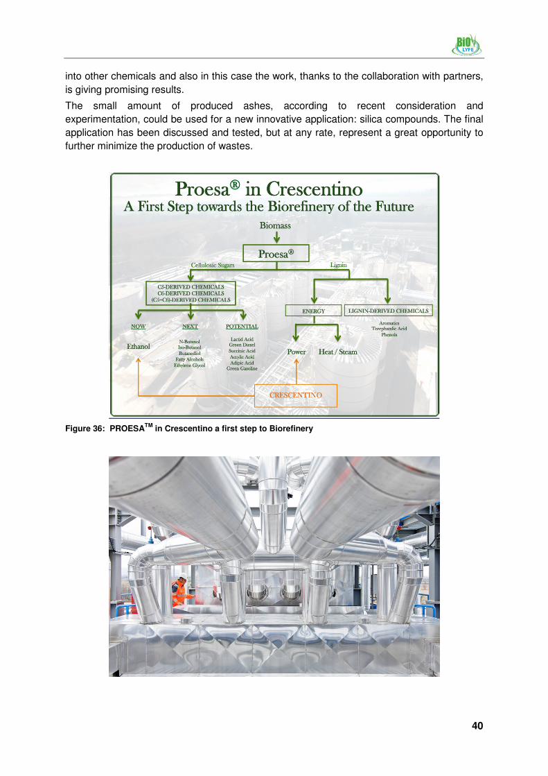
into other chemicals and also in this case the work, thanks to the collaboration with partners,
is giving promising results.
The small amount of produced ashes, according to recent consideration and
experimentation, could be used for a new innovative application: silica compounds. The final
application has been discussed and tested, but at any rate, represent a great opportunity to
further minimize the production of wastes.
Figure 36: PROESATM
in Crescentino a first step to Biorefinery

41
Part I Overview on the lignocellulosic ethanol production
1 Introduction RITA MERGNER, RAINER JANSSEN
2 Components of lignocellulosic feedstock RITA MERGNER, RAINER JANSSEN
3 Feedstock provision FABIO SISSOT
4 Pretreatment technologies ISABELLA DE BARI
5 Hydrolysis processes RITA MERGNER, RAINER JANSSEN
6 Fermentation and process configurations RITA MERGNER, RAINER JANSSEN
7 Downstream processing (DSP) RITA MERGNER, RAINER JANSSEN
8 Demonstration projects RITA MERGNER, RAINER JANSSEN

42
List of Figures
Figure 1: Night view of Crescentino ethanol plant ............................................................... 7
Figure 2: Basic scheme of second generation bioethanol production .................................. 8
Figure 3: Field operations ................................................................................................... 9
Figure 4: Aerial view of the Crescentino ethanol plant .......................................................11
Figure 5: Crescentino plant site layout ...............................................................................11
Figure 6: Inauguration of the area dedicated to the construction ........................................13
Figure 7: Construction timeline ..........................................................................................14
Figure 8: Plant constructed at present day .........................................................................14
Figure 9: Crescentino ethanol plant inauguration (October, 9th 2013) ................................15
Figure 10: Biomass storage ................................................................................................15
Figure 11: Biomass fed in the conveyor system ..................................................................16
Figure 12: Arundo donax productive cycle from plowing to trasformation ............................17
Figure 13: Biomass moved by telehandler inside the storage area ......................................18
Figure 14: The conveyor system after the debaling .............................................................18
Figure 15: Pretreatment area ..............................................................................................19
Figure 16: The pretreatment area with the biomass feeding system ....................................19
Figure 17: Advantages of Biochemtex proprietary technology .............................................22
Figure 18: Compounds that could inhibit the microorganism activity ...................................22
Figure 19: The pretreatment area behind the fermenters ....................................................23
Figure 20: The pretreatment area ........................................................................................23
Figure 21: Pretreatment area ..............................................................................................24
Figure 22: A frontal view of the area ....................................................................................24
Figure 23: Block scheme of Crescentino viscosity reduction/enzymatic hydrolysis section ..25
Figure 24: Mechanism for the enzymatic cellulose hydrolysis .............................................26
Figure 25: Comparison between standard and new Chemtex technology ...........................27
Figure 26: Fermentation area ..............................................................................................28
Figure 27: Fermentation area ..............................................................................................29
Figure 28: Block scheme of Crescentino fermentation section ............................................30
Figure 29: CIP and beer well area .......................................................................................32
Figure 30: Distilation area ...................................................................................................33
Figure 31: Ethanol Storage and distillation area ..................................................................33
Figure 32: Filtration system block flow diagram ...................................................................35
Figure 33: Waste water treatment area ...............................................................................36
Figure 34: Lignin power plant ..............................................................................................38
Figure 35: Basic idea of Biohemtex illustrating PROESATM Technology ..............................39
Figure 36: PROESATM in Crescentino a first step to Biorefinery ..........................................40

43
List of Tables
Table 1: Anhydrous fuel ethanol specifications .................................................................12
Table 2: Qualitative effect of various pre-treatments on the biomass structure .................21
Table 3: Anhydrous fuel ethanol specifications .................................................................37
Table 4: Conversion of temperature units .........................................................................51
Table 5: Conversion of pressure units ..............................................................................51
Table 6: Metric prefixes ....................................................................................................51
Table 7: Conversion of energy units .................................................................................52
Table 8: Conversion of volume units .................................................................................52
Table 9: Conversion factors for ethanol ............................................................................52

44
Glossary
The Glossary and Abbreviations list describes and defines various specific or common expressions, terms and words, which are used in this handbook. Several expressions are adapted from Wikipedia.
Acidity: The presence of acid-type constituents whose concentration is usually defined in terms of neutralization number. The constituents vary in nature and may or may not markedly influence the behavior of e.g. oils.
Additives: Chemicals added to fuel in very small quantities to improve and maintain fuel quality. Detergents and corrosion inhibitors are examples of gasoline additives.
Alcohols: Organic compounds that are distinguished from hydrocarbons by the inclusion of a hydroxyl group. The two simplest alcohols are methanol and ethanol.
Aldehydes: A class of organic compounds derived by removing the hydrogen atoms from an alcohol. Aldehydes can be produced from the oxidation of an alcohol.
Aliphatic: A class of saturated or unsaturated carbon compounds, in which the carbon atoms are joined in open chains.
Alternative Fuel: Fuel which is not broadly applied today and which is a niche product in the fuel market.
Anhydrous: Describes a compound that does not contain any water.
Anhydrous alcohol: Alcohol that is free of water and at least 99% pure. This ethanol may be used in fuel blends. Hydrous alcohol on the other hand contains some water and usually has a purity of 96%. In Brazil, this ethanol is being used as a 100% gasoline substitute in cars with dedicated engines. The distinction between anhydrous and hydrous alcohol is of relevance not only in the fuel sector but may be regarded as the basic quality distinction in the ethanol market.
Aromatics: Hydrocarbons based on the ringed six-carbon benzene series or related organic groups. Benzene, toluene and xylene are the principal aromatics, commonly referred to as the BTX group. They represent one of the heaviest fractions in gasoline.
Bagasse: By-product of sugarcane production. It is the biomass remaining after sugarcane stalks are crushed to extract their juice. Bagasse is often used as a primary fuel source for sugar mills; when burned in quantity, it produces sufficient heat energy to supply all the needs of a typical sugar mill, with energy to spare.
Barrel: A unit of volume measurement used for petroleum and its products. 1 barrel (bbl) = 42 U.S. gallons or 35 British gallons.
Biochemical Conversion: The use of enzymes and catalysts to change biological substances chemically to produce energy products.
Biodiesel: Biodiesel is composed of monoalkyl esters (methyl/ethyl esters), a long chain of fatty acids derived from renewable lipid sources. It is an ester based, renewable fuel made from vegetable oils, recycled fryer oils, tallow and other biological products which have had their viscosity reduced using a process called tranestrification. The by-product of this process is glycerin, the thick component of vegetable oil. Biodiesel is biodegradable, non-toxic, and essentially free of sulfur and aromatics. Originally biodiesel was considered a by-product of glycerin soap production.
Bio-ETBE: Ethyl-Tertio-Butyl-Ether produced from bioethanol. ETBE is used as a fuel additive to increase the octane rating and reduce knocking.

45
Bioethanol: Ethanol produced from biomass and/or the biodegradable fraction of waste, for use as biofuel E5 contains 5% ethanol and 95% petrol E85 contains 85% ethanol and 15% petrol
Biofuel: Liquid or gaseous fuel for transport produced from biomass: Alcohols, esters, ethers, and other chemicals (biodiesel, ethanol, and methane) made from biomass sources (herbaceous and woody plants, animal fats, agricultural and forest waste, or municipal solid and industrial waste) within an active carbon cycle. Production and combustion of biofuels take and replenish the CO2 in a circular, sustainable fashion. These fuels are used for stationary and mobile applications, i.e., electricity and transportation. Two commonly used biofuels are ethanol and biodiesel.
Biogas: A fuel gas produced from biomass and/or the biodegradable fraction of waste, which can be purified to natural gas quality (biomethane) for use as biofuel or woodgas.
Biomass: Renewable organic matter such as agricultural crops, crop waste residues, wood, animal waste, animal fat, municipal waste, aquatic plants; fungal growth; etc., used for the production of energy.
Biomass-to-Liquid (BTL): This second-generation fuel belongs to the group of synthetic fuels. Its components are designed for the requirements of modern motor concepts. For the production of BTL-fuels many types of feedstock can be used.
Blending: Mixing of two compatible fuels having different properties in order to produce an intermediate fuel.
BTL: Biomass-to-Liquid
CAP: Common Agricultural Policy in the EU
Carbon Dioxide (CO2): A product of combustion that has become an environmental concern in recent years. CO2 does not directly impair human health, but is a greenhouse gas that traps the Earth's heat and contributes to the potential for global warming.
Carbon Monoxide (CO): A colorless, odorless gas produced by the incomplete combustion of fuels with a limited oxygen supply, as in automobile engines. CO contributes to the formation of smog ground-level ozone, which can trigger serious respiratory problems.
Catalyst: A substance whose presence changes the rate of chemical reaction without itself undergoing permanent change in its composition. Catalysts may be accelerators or retarders. Most inorganic catalysts are powdered metals and metal oxides, chiefly used in the petroleum, vehicle, and heavy chemical industries.
CBP: combined bioprocessing
Centrifuge: A machine using centrifugal force produced by high-speed rotation for separating materials of different densities. Applied to Diesel engine fuels and lubricating oils to remove moisture and other extraneous materials.
Cetane Number (Cetane Rating, Cetane Index): A measure of ignition quality of diesel fuel. The higher the cetane number, the easier the fuel ignites when it is injected into the engine. Biodiesel has a higher cetane number than petrol diesel because of its higher oxygen content. This means that engines run smoother and create less noise when running on Biodiesel. It is the equivalent to the octane number of gasoline.
CH4: Methane
CO: Carbon monoxide
CO2: Carbon dioxide
Combined bioprocessing (CBP): technology for cellulosic ethanol production

46
Common Agricultural Policy (CAP): The CAP is a system of European Union agricultural subsidies. These subsidies work by guaranteeing a minimum price to producers and by direct payment of a subsidy for crops planted. This provides some economic certainty for EU farmers and production of a certain quantity of agricultural goods.
Corrosion: Detrimental change in the size or characteristics of material under conditions of exposure or use. It usually results from chemical action either regularly and slowly, as in rusting (oxidation), or rapidly, as in metal pickling.
Cryogenic Storage: Extreme low-temperature storage.
Density: Density is the term meaning the mass of a unit of volume. Its numerical expression varies with the units selected.
Detergent: Additives used to inhibit deposit formation in the fuel and intake systems in automobiles.
Distillation: Distillation is a method of separating substances based on differences in their volatilities. In the distillation process a liquid is heated up to its boiling point and the vapors are collected after condensing. This process is used for ethanol production.
E10 (Gasohol): Ethanol mixture that contains 10% ethanol, 90% unleaded gasoline.
E85, E93, E95: Ethanol/gasoline mixture that contains 85% (93%, 95%) denatured ethanol and 15% (5%, 2%) gasoline, by volume.
EC: European Commission
ETBE: Ethyl tertiary butyl ester
Ethanol: (also known as Ethyl Alcohol, Grain Alcohol, CH3CH2OH) Can be produced chemically from ethylene or biologically from the fermentation of various sugars from carbohydrates found in agricultural crops and cellulosic residues from crops or wood.
Ethyl Tertiary Butyl Ether (ETBE): A fuel oxygenate used as a gasoline additive to increase octane and reduce engine knock.
EU: European Union
Fahrenheit: Temperature scale based on 32F for the temperature at which water freezes and 212F for the temperature at which water boils (180 difference). Conversion to Fahrenheit from Celsius (centigrade) temperature scale is by the following formula: F = 9/5C + 32, where C is the temperature in Celsius degrees.
Feedstock: Any material converted to another form of fuel or energy product. For example, cornstarch can be used as a feedstock for ethanol production.
Fermentation: The enzymatic transformation by microorganisms of organic compounds such as sugar. It is usually accompanied by the evolution of gas as the fermentation of glucose into ethanol and CO2.
FFV: Flexible fuel vehicle
First-generation feedstock: Feedstock which is used to produce first generation biofuels. Usually, this feedstock was originally cultivated for food production. It comprises only parts of the plants, such as stalks, kernels and tubes. Examples are rape-seed, cereals, potatoes, sugar-cane etc.
First generation biofuels: Biofuels which are available on todays fuel markets, such as PPO, biodiesel and bioethanol.
Flash point: The lowest temperature in °C at which a liquid will produce enough vapor to ignite, if the vapor is flammable and when exposed to a source of ignition. The lower the

47
flashpoint is the higher is the risk of fire. Biodiesel has an abnormally high flashpoint (for a fuel), making it very safe to handle and store.
Flexible-Fuel Vehicle (FFV): A Vehicle with a common fuel tank designed to run on varying blends of unleaded gasoline with either ethanol or methanol.
Fossil Fuel: A hydrocarbon deposit, such as petroleum, coal, or natural gas, derived from living matter of a previous geologic time and used for fuel. Combustion of fossil fuels emits large amounts of CO2 into the atmosphere.
GHG: Greenhouse gas
HC: Hydrocarbons
HHV: Higher heating value
High Compression Ignition Engine: Also know as Diesel engine. Unlike gasoline engines which use a spark plug to ignite the fuel, there is no external ignition spark in a high compression engine. Air is compressed, driving its temperature up to a point that it ignites fuel which has been injected into the chamber.
Hydrocarbons: Compounds containing various combinations of hydrogen and carbon atoms. Hydrocarbons contribute heavily to smog.
Hydrogen (H2): A colorless, highly flammable gaseous fuel.
Hydrous alcohol: Alcohol that contains some water and usually has a purity of 96%. In Brazil, this ethanol is being used as a 100% gasoline substitute in cars with dedicated engines. The distinction between anhydrous and hydrous alcohol is of relevance not only in the fuel sector but may be regarded as the basic quality distinction in the ethanol market.
Indirect Land Use Change (ILUC): When biofuels are produced on existing agricultural land, the demand for food and feed crops remains, and may lead to someone producing more food and feed somewhere else. This can imply land use change (by changing e.g. forest into agricultural land), which implies that a substantial amount of CO2 emissions are released into the atmosphere.
Infrastructure: In transportation, this term generally refers to the charging and fueling network necessary to successful development, production, commercialization, and operation of alternative fuel vehicles. It includes fuel supply, public and private charging and fueling facilities, standard specifications for fueling outlets, customer service, education and training, and building code regulations.
Kinematic Viscosity: The ratio of the absolute viscosity of a liquid to its specific gravity at the temperature at which the viscosity is measured. Expressed in Stokes or Centistokes.
LHV: Lower Heating Value
Methane (CH4): The simplest of the hydrocarbons and the principal constituent of natural gas. Pure methane has a heating value of 1,012 Btu per standard cubic foot.
Methanol (Methyl Alcohol, Wood Alcohol, CH3OH): A liquid fuel formed by catalytically combining CO with hydrogen in a 1 to 2 ratio under high temperature and pressure. Commercially, it is typically manufactured by steam reforming natural gas. Also formed in the destructive distillation of wood. It is commonly used in biodiesel for its reactivity.
Methyl Alcohol: See Methanol.
MJ: Megajoule
MON: Motor Octane Number

48
Motor Octane: The octane as tested in a single-cylinder octane test engine at more severe operating conditions. Motor octane number (MON) affects high-speed and part-throttle knock and performance under load, passing, climbing, and other operating conditions. Motor octane is represented by the designation M in the (R+M)/2 equation and is the lower of the two numbers.
NOx: Oxides of nitrogen
OECD: Organization of Economic Co-operation and Development
Octane Enhancer: Any substance such as MTBE, ETBE, toluene, or xylene that is added to gasoline to increase octane and reduce engine knock.
Octane Rating (Octane Number): A measure of a fuel's resistance to self-ignition, hence a measure as well of the antiknock properties of the fuel.
Olefins: Class of unsaturated paraffin hydrocarbons recovered from petroleum. Typical examples include: butene, ethylene and propylene.
Oxidation: Combining elemental compounds with oxygen to form a new compound. A part of the metabolic reaction.
Oxides of Nitrogen (NOx): Regulated air pollutants, primarily NO and NO2 but including other substances in minute concentrations. Under the high pressure and temperature conditions in an engine, nitrogen and oxygen atoms in the air react to form various NOx. Like hydrocarbons, NOx are precursors to the formation of smog. They also contribute to the formation of acid rain.
Oxidizing agent: Any substance (oxygen, chlorine) that can accept electrons. When oxygen or chlorine is added to wastewater, organic substances are oxidized. These oxidized organic substances are more stable and less likely to give off odors or to contain disease bacteria.
Oxygenate: A term used in the petroleum industry to denote fuel additives containing hydrogen, carbon, and oxygen in their molecular structure. It includes ethers such as MTBE and ETBE and alcohols such as ethanol and methanol.
Ozone (O3): Tropospheric ozone (smog) is formed when volatile organic compounds (VOCs), oxygen, and NOx react in the presence of sunlight (not to be confused with stratospheric ozone, which is found in the upper atmosphere and protects the earth from the sun's ultraviolet rays). Though beneficial in the upper atmosphere, ground-level ozone is a respiratory irritant and considered a pollutant.
Ozonation: The application of ozone to water, wastewater, or air, generally for the purposes of disinfection or odor control.
Petrochemical: An intermediate chemical derived from petroleum, hydrocarbon liquids or natural gas, such as: ethylene, propylene, benzene, toluene and xylene.
pH: pH is an expression of the intensity of the basic or acidic condition of a liquid. Mathematically, pH is the logarithm (base 10) of the reciprocal of the hydrogen ion concentration. The pH may range from 0 to 14, where 0 is most acidic, 14 most basic, and 7 is neutral. Natural waters usually have a pH between 6.5 and 8.5.
Phenol: An organic compound that is an alcohol derivative of benzene.
Polymer: A chemical formed by the union of many monomers (a molecule of low molecular weight). Polymers are used with other chemical coagulants to aid in binding small suspended particles to form larger chemical flocs for easier removal from water. All polyelectrolytes are polymers, but not all polymers are polyelectrolytes.
Polymerization: Process of combining two or more simple molecules of the same type, called monomers, to form a single molecule having the same elements in the same

49
proportion as in the original molecules, but having increased molecular weight. The product of the combination is a polymer.
Propane (C3H8): A gas whose molecules are composed of three carbon and eight hydrogen atoms. Propane is present in most natural gas in the United States, and is refined from crude petroleum. Propane contains about 2,500 Btu per standard cubic foot. Propane is the principal constituent in liquefied petroleum gas (LPG).
R&D: Research and development
Refinery: A plan used to separate the various components present in crude oil and convert them into usable products or feedstock for other processes.
Renewable Energy: Designated commodity or resource, such as solar energy, biodiesel fuel, or firewood, that is inexhaustible or replaceable by new growth.
Research Octane Number (RON): The octane as tested in a single-cylinder octane test engine operated under less severe operating conditions. RON affects low-to medium-speed knock and engine run-on.
Second generation biofuel: Biofuel which is not yet competitive and available on the fuel market. It is made from second generation feedstock, such as cellulosic materials and plants. An example is BtL fuel.
SHF: Separate hydrolysis and fermentation (technology for cellulosic ethanol production)
Sodium Hydroxide (Caustic Soda, Lye, NaOH): It is a metallic alkaline salt that is extremely corrosive and is used in Biodiesel production to make methoxide.
Soluble: Matter or compounds capable of dissolving into a solution.
Solvent: A substance, normally a liquid, which is capable of absorbing another liquid, gas, or solid to form a homogeneous mixture.
SOx: Oxides of sulfur
SSF: Simultaneous saccarification and fermentation (technology for cellulosic ethanol production)
Sulfur (S): An element that is present in crude oil and natural gas as an impurity in the form of its various compounds.
Surfactant: Surface-active agent. It is the active agent in detergents that possesses a high cleaning ability.
Tax Incentives: In general, a means of employing the tax code to stimulate investment in or development of a socially desirable economic objective without direct expenditure from the budget of a given unit of government. Such incentives can take the form of tax exemptions or credits.
Toxic: A substance which is poisonous to a living organism.
Vapor Pressure or Volatility: The tendency of a liquid to pass into the vapor state at a given temperature. With automotive fuels, volatility is determined by measuring RVP.
Viscosity: Measure of the internal friction or resistance of an oil to flow. As the temperature of an oil is increased, its viscosity decreases and it is therefore able to flow more readily. Biodiesel is much less viscous than the oil from which it is made. Viscosity is measured on several different scales, including Redwood No. 1 at 100F, Engler Degrees, Saybolt Seconds, etc. The most common method for designation of viscosity is kinematic viscosity, measured in centistokes.
50
Volatile: A volatile substance is one that is capable of being evaporated or changed to a vapor at a relatively low temperature. Volatile substances also can be partially removed by air stripping.
Volatile Organic Compound (VOC): Reactive gas released during combustion or evaporation of fuel. VOCs are a major component of air pollution and react with NOx in the presence of sunlight and form ozone. A wide range of carbon-based molecules, such as aldehydes, ketones, and hydrocarbons are VOC's.
Volatility: Ability of a substance (gasoline) to turn from a liquid to a vapor. Low volatility refers to low RVP, indicating less light hydrocarbons in the gasoline front end.

51
General conversion units
Table 4: Conversion of temperature units
Unit Celsius Kelvin Fahrenheit
Celsius °C °C = K − 273.15 °C = (°F − 32) × 1.8
Kelvin K K = °C + 273.15 K = (°F + 459.67) × 1.8
Fahrenheit °F °F = °C × 1.8 + 32 °F = K × 1.8 – 459.67
Table 5: Conversion of pressure units (pascal, bar, technical atmosphere, standard atmosphere, torr, pound per square inch)
Pa bar at atm Torr psi
1 Pa
0.00001 0.000010197 9.8692×10⁻⁶
0.0075006 0.0001450377
1 bar 100,000
1.0197 0.98692 750.06 14.50377
1 at 98,066.5 0.980665
0.9678411 735.5592 14.22334
1 atm 101,325 1.01325 1.0332
760 14.69595
1 Torr 133.3224 0.001333224 0.001359551 0.001315789
0.01933678
1 psi 6894.8 0.068948 0.0703069 0.068046 51.71493
Table 6: Metric prefixes
Prefix Symbol 10n
pico p 10-12
nano n 10-9
micro μ 10-6
deca da 101
kilo k 103
mega M 106
giga G 109
tera P 1012

52
Table 7: Conversion of energy units
kJ kcal Wh Btu
1 kJ
0.2388459 0.27777778 0.94781708
1 kcal 4.1868
1,163 3.96832054
1 Wh 3.6 0.85984523
3.41214148
1Btu 1.0550559 0.25199577 2.29307108
Table 8: Conversion of volume units
L m
3 US gallons in
3
1 L
0.001 0.26417205 61.02374409
1 m3 1,000
264.17205 61.023,74409
1 US gallon 3.78541 0.00378541
231
1 in3 0.01639 0.00001639 0.004329
Table 9: Conversion factors for ethanol
Ethanol kg toe GJ
1 L 0.789 0.02106
1 m3
0.51
