2 engine layout and load diagrams - Клуб Судовых...
TRANSCRIPT

2 Engine Layout and Load Diagrams
Propulsion and Engine Running Points
Propeller curve
The relation between power and propeller speed fora fixed pitch propeller is as mentioned above de-scribed by means of the propeller law, i.e. the thirdpower curve:
Pb = c x n3 , in which:
Pb = engine power for propulsionn = propeller speedc = constant
The power functions Pb = c x ni will be linear func-tions when using logarithmic scales.
Therefore, in the Layout Diagrams and Load Dia-grams for diesel engines, logarithmic scales areused, making simple diagrams with straight lines.
Propeller design point
Normally, estimations of the necessary propellerpower and speed are based on theoretical calcula-tions for loaded ship, and often experimental tanktests, both assuming optimum operating condi-tions, i.e. a clean hull and good weather. The combi-nation of speed and power obtained may be calledthe ship’s propeller design point (PD), placed on thelight running propeller curve 6. See Fig. 2.01. On theother hand, some shipyards, and/or propeller manu-facturers sometimes use a propeller design point(PD’) that incorporates all or part of the so-calledsea margin described below.
Fouled hull
When the ship has sailed for some time, the hull andpropeller become fouled and the hull’s resistancewill increase. Consequently, the ship speed will bereduced unless the engine delivers more power tothe propeller, i.e. the propeller will be further loadedand will be heavy running (HR).
As modern vessels with a relatively high servicespeed are prepared with very smooth propeller and
hull surfaces, the fouling after sea trial, therefore,will involve a relatively higher resistance and therebya heavier running propeller.
Sea margin at heavy weather
If, at the same time the weather is bad, with headwinds, the ship’s resistance may increase com-pared to operating at calm weather conditions.
When determining the necessary engine power, it istherefore normal practice to add an extra powermargin, the so-called sea margin, see Fig. 2.02which is traditionally about 15% of the propeller de-sign (PD) power.
Engine layout (heavy propeller)
When determining the necessary engine speedconsidering the influence of a heavy running propel-ler for operating at large extra ship resistance, it isrecommended - compared to the clean hull andcalm weather propeller curve 6 - to choose a heavierpropeller curve 2 for engine layout, and the propeller
MAN B&W Diesel A/S Engine Selection Guide
402 000 004 198 22 30
2.01
Line 2 Propulsion curve, fouled hull and heavy weather(heavy running), recommended for engine layout
Line 6 Propulsion curve, clean hull and calm weather(light running), for propeller layout
MP Specified MCR for propulsionSP Continuous service rating for propulsionPD Propeller design pointHR Heavy runningLR Light running
Fig. 2.01: Ship propulsion running points and engine layout
178 05 41-5.3

curve for clean hull and calm weather in curve 6 willbe said to represent a “light running” (LR) propeller,see area 6 on Figs. 2.07a and 2.07b.
Compared to the heavy engine layout curve 2 werecommend to use a light running of 3.0-7.0% fordesign of the propeller, with 5% as a good average.
Engine margin
Besides the sea margin, a so-called “engine mar-gin” of some 10% is frequently added. The corre-sponding point is called the “specified MCR for pro-pulsion” (MP), and refers to the fact that the powerfor point SP is 10% lower than for point MP, see Fig.2.01. Point MP is identical to the engine’s specifiedMCR point (M) unless a main engine driven shaftgenerator is installed. In such a case, the extrapower demand of the shaft generator must also beconsidered.
Note:Light/heavy running, fouling and sea margin areoverlapping terms. Light/heavy running of the pro-peller refers to hull and propeller deterioration andheavy weather and, – sea margin i.e. extra power tothe propeller, refers to the influence of the wind andthe sea. However, the degree of light running mustbe decided upon experience from the actual tradeand hull design.
402 000 004 198 22 30
MAN B&W Diesel A/S Engine Selection Guide
2.02
178 05 67-7.1
Fig. 2.02: Sea margin based on weather conditions in theNorth Atlantic Ocean. Percentage of time at sea wherethe service speed can be maintained, related to the extrapower (sea margin) in % of the sea trial power.
MAN B&W Diesel A/S Engine Selection Guide
402 000 004 198 22 30
Influence of propeller diameter and pitch onthe optimum propeller speed
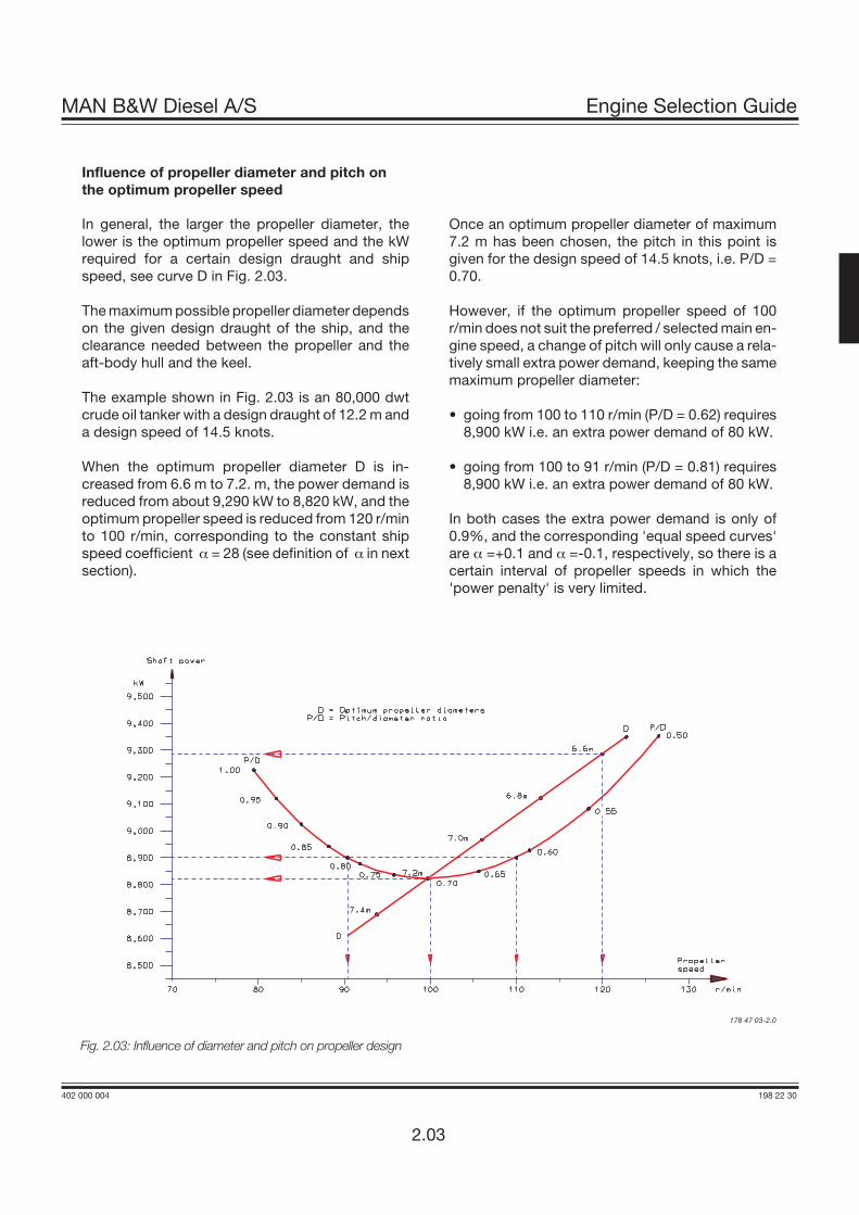
In general, the larger the propeller diameter, thelower is the optimum propeller speed and the kWrequired for a certain design draught and shipspeed, see curve D in Fig. 2.03.
The maximum possible propeller diameter dependson the given design draught of the ship, and theclearance needed between the propeller and theaft-body hull and the keel.
The example shown in Fig. 2.03 is an 80,000 dwtcrude oil tanker with a design draught of 12.2 m anda design speed of 14.5 knots.
When the optimum propeller diameter D is in-creased from 6.6 m to 7.2. m, the power demand isreduced from about 9,290 kW to 8,820 kW, and theoptimum propeller speed is reduced from 120 r/minto 100 r/min, corresponding to the constant shipspeed coefficient a = 28 (see definition of a in nextsection).
Once an optimum propeller diameter of maximum7.2 m has been chosen, the pitch in this point isgiven for the design speed of 14.5 knots, i.e. P/D =0.70.
However, if the optimum propeller speed of 100r/min does not suit the preferred / selected main en-gine speed, a change of pitch will only cause a rela-tively small extra power demand, keeping the samemaximum propeller diameter:
• going from 100 to 110 r/min (P/D = 0.62) requires8,900 kW i.e. an extra power demand of 80 kW.
• going from 100 to 91 r/min (P/D = 0.81) requires8,900 kW i.e. an extra power demand of 80 kW.
In both cases the extra power demand is only of0.9%, and the corresponding 'equal speed curves'are a =+0.1 and a =-0.1, respectively, so there is acertain interval of propeller speeds in which the'power penalty' is very limited.
2.03
178 47 03-2.0
Fig. 2.03: Influence of diameter and pitch on propeller design
Constant ship speed lines
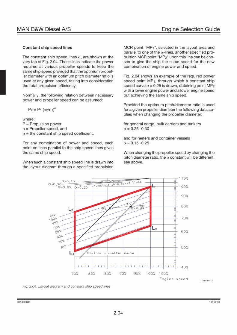
The constant ship speed lines a, are shown at thevery top of Fig. 2.04. These lines indicate the powerrequired at various propeller speeds to keep thesame ship speed provided that the optimum propel-ler diameter with an optimum pitch diameter ratio isused at any given speed, taking into considerationthe total propulsion efficiency.
Normally, the following relation between necessarypower and propeller speed can be assumed:
P2 = P1 (n2/n1)a
where:P = Propulsion powern = Propeller speed, anda = the constant ship speed coefficient.
For any combination of power and speed, eachpoint on lines parallel to the ship speed lines givesthe same ship speed.
When such a constant ship speed line is drawn intothe layout diagram through a specified propulsion
MCR point "MP1", selected in the layout area andparallel to one of the a-lines, another specified pro-pulsion MCR point "MP2" upon this line can be cho-sen to give the ship the same speed for the newcombination of engine power and speed.
Fig. 2.04 shows an example of the required powerspeed point MP1, through which a constant shipspeed curve a = 0.25 is drawn, obtaining point MP2with a lower engine power and a lower engine speedbut achieving the same ship speed.
Provided the optimum pitch/diameter ratio is usedfor a given propeller diameter the following data ap-plies when changing the propeller diameter:
for general cargo, bulk carriers and tankersa = 0.25 -0.30
and for reefers and container vesselsa = 0.15 -0.25
When changing the propeller speed by changing thepitch diameter ratio, the a constant will be different,see above.
402 000 004 198 22 30
MAN B&W Diesel A/S Engine Selection Guide
2.04
Fig. 2.04: Layout diagram and constant ship speed lines
178 05 66-7.0

Engine Layout Diagram
The layout procedure has to be carefully consideredbecause the final layout choice will have a consider-able influence on the operating condition of the mainengine throughout the whole lifetime of the ship. Thefactors that should be conisdered are operational flex-ibility, fuel consumption, obtainable power, possibleshaft generator application and propulsion efficiency.
An engine’s layout diagram is limited by two constantmean effective pressure (mep) lines L1-L3 and L2-L4,and by two constant engine speed lines L1-L2 andL3-L4, see Fig. 2.04. The L1 point refers to the engine’snominal maximum continuous rating.
Please note that the areas of the layout diagrams aredifferent for the engines types, see Fig. 2.05.
Within the layout area there is full freedom to select theengine’s specified MCR point M which suits the de-mand of propeller power and speed for the ship.
On the X-axis the engine speed and on the Y-axis theengine power are shown in percentage scales. Thescales are logarithmic which means that, in this dia-gram, power function curves like propeller curves (3rdpower), constant mean effective pressure curves (1stpower) and constant ship speed curves (0.15 to 0.30power) are straight lines.
Fig. 2.06 shows, by means of superimposed diagramsfor all engine types, the entire layout area for theMC-programme in a power/speed diagram. As can beseen, there is a considerable overlap of power/speedcombinations so that for nearly all applications, thereis a wide section of different engines to choose from allof which meet the individual ship's requirements.
Specified maximum continuous rating, SMCR = “M”
Based on the propulsion and engine running points,as previously found, the layout diagram of a relevantmain engine may be drawn-in. The specified MCRpoint (M) must be inside the limitation lines of the lay-out diagram; if it is not, the propeller speed will have tobe changed or another main engine type must be cho-sen. Yet, in special cases point M may be located tothe right of the line L1-L2, see “Optimising Point”.
MAN B&W Diesel A/S Engine Selection Guide
402 000 004 198 22 30
2.05
Power
Speed
L2
L1
L4
L3
Layout diagram of100 - 64% power and100 - 75% speed rangevalid for the types:L90MC-C S60MC-C
K90MC S60MC
S80MC-C L60MC
S80MC S50MC-C
L80MC S50MC
S70MC-C L50MC
S70MC L42MC
L70MC
Power
Speed
L2
L1
L4
L3
Layout diagram of100 - 80% power and100 - 80% speed rangevalid for the types:S90MC-C
Power
L2
L1
L4
L3
Layout diagram of100 - 80% power and100 - 85% speed rangevalid for the types:K90MC-C
K80MC-C
S46MC-C
S42MC
S35MC
L35MC
S26MC
Power
Speed
L2
L1
L4
L3
Layout diagram of100 - 80% power and100 - 90% speed rangevalid for the types:K98MC
K98MC-C
Speed
178 13 85-1.4Fig. 2.05: Layout diagram sizes

402 000 004 198 22 30
MAN B&W Diesel A/S Engine Selection Guide
2.06
Fig. 2.06: Layout diagrams of the two-stroke engine MC-programme as per January 2000178 13 80-2.8

Continuous service rating (S)
The Continuous service rating is the power at whichthe engine is normally assumed to operate, andpoint S is identical to the service propulsion point(SP) unless a main engine driven shaft generator isinstalled.
Optimising point (O)
The optimising point O is the rating at which theturbocharger is matched, and at which the engine tim-ing and compression ratio are adjusted.
On engines with Variable Injection Timing (VIT) fuelpumps, the optimising point (O) can be different thanthe specified MCR (M), whereas on engines withoutVIT fuel pumps “O” has to coincide with “M”.
The large engine types have VIT fuel pumps as stan-dard, but on some types these pumps are an option.Small-bore engines are not fitted with VIT fuel pumps.
Type With VIT Without VITK98MC BasicK98MC-C BasicS90MC-C BasicL90MC-C BasicK90MC BasicK90MC-C BasicS80MC-C BasicS80MC BasicL80MC BasicS70MC-C Optional BasicS70MC BasicL70MC BasicS60MC-C Optional BasicS60MC BasicL60MC BasicS50MC-C Optional BasicS50MC BasicS46MC-C BasicS42MC BasicL42MC BasicS35MC BasicL35MC BasicS26MC Basic
Engines with VIT
The optimising point O is placed on line 1 of the loaddiagram, and the optimised power can be from 85 to100% of point M's power, when turbocharger(s) andengine timing are taken into consideration. Whenoptimising between 93.5% and 100% of point M'spower, 10% overload running will still be possible(110% of M).
The optimising point O is to be placed inside the lay-out diagram. In fact, the specified MCR point M can,in special cases, be placed outside the layout dia-gram, but only by exceeding line L1-L2, and ofcourse, only provided that the optimising point O islocated inside the layout diagram and provided thatthe specified MCR power is not higher than the L1power.
Engine without VITOptimising point (O) = specified MCR (M)
On engine types not fitted with VIT fuel pumps,the specified MCR – point M has to coincide withpoint O.
MAN B&W Diesel A/S Engine Selection Guide
402 000 004 198 22 30
2.07

Load Diagram
Definitions
The load diagram, Figs. 2.07, defines the power andspeed limits for continuous as well as overload op-eration of an installed engine having an optimisingpoint O and a specified MCR point M that confirmsthe ship’s specification.
Point A is a 100% speed and power reference pointof the load diagram, and is defined as the point onthe propeller curve (line 1), through the optimisingpoint O, having the specified MCR power. Normally,point M is equal to point A, but in special cases, forexample if a shaft generator is installed, point M maybe placed to the right of point A on line 7.
The service points of the installed engine incorpo-rate the engine power required for ship propulsionand shaft generator, if installed.
Limits for continuous operation
The continuous service range is limited by four lines:
Line 3 and line 9:Line 3 represents the maximum acceptable speedfor continuous operation, i.e. 105% of A.
If, in special cases, A is located to the right of lineL1-L2, the maximum limit, however, is 105% of L1.
During trial conditions the maximum speed may beextended to 107% of A, see line 9.
The above limits may in general be extended to105%, and during trial conditions to 107%, of thenominal L1 speed of the engine, provided the tor-sional vibration conditions permit.
The overspeed set-point is 109% of the speed in A,however, it may be moved to 109% of the nominalspeed in L1, provided that torsional vibration condi-tions permit.
Running above 100% of the nominal L1 speed at aload lower than about 65% specified MCR is, how-ever, to be avoided for extended periods. Onlyplants with controllable pitch propellers can reachthis light running area.
Line 4:Represents the limit at which an ample air supplyis available for combustion and imposes a limita-tion on the maximum combination of torque andspeed.
Line 5:Represents the maximum mean effective pressurelevel (mep), which can be accepted for continuousoperation.
Line 7:Represents the maximum power for continuousoperation.7
Limits for overload operation
The overload service range is limited as follows:
Line 8:Represents the overload operation limitations.
The area between lines 4, 5, 7 and the heavy dashedline 8 is available for overload running for limited pe-riods only (1 hour per 12 hours).
402 000 004 198 22 30
MAN B&W Diesel A/S Engine Selection Guide
2.08
A 100% reference point
M Specified MCR point
O Optimising point
Line 1 Propeller curve through optimising point (i = 3)(engine layout curve)
Line 2 Propeller curve, fouled hull and heavy weather– heavy running (i = 3)
Line 3 Speed limit
Line 4 Torque/speed limit (i = 2)
Line 5 Mean effective pressure limit (i = 1)
Line 6 Propeller curve, clean hull and calm weather –light running (i = 3), for propeller layout
Line 7 Power limit for continuous running (i = 0)
Line 8 Overload limit
Line 9 Speed limit at sea trial
Point M to be located on line 7 (normally in point A)
Regarding “i” in the power functions Pb = c x ni, seepage 2.01

MAN B&W Diesel A/S Engine Selection Guide
402 000 004 198 22 30
Fig. 2.07a: Engine load diagram for engine with VIT
Fig. 2.07b: Engine load diagram for engine without VIT
2.09
178 05 42-7.3178 05 42-7.3
178 39 18-4.1

Recommendation
Continuous operation without limitations is allowedonly within the area limited by lines 4, 5, 7 and 3 ofthe load diagram, except for CP propeller plantsmentioned in the previous section.
The area between lines 4 and 1 is available for oper-ation in shallow waters, heavy weather and duringacceleration, i.e. for non-steady operation withoutany strict time limitation.
After some time in operation, the ship’s hull and pro-peller will be fouled, resulting in heavier running ofthe propeller, i.e. the propeller curve will move to theleft from line 6 towards line 2, and extra power is re-quired for propulsion in order to keep the ship’sspeed.
In calm weather conditions, the extent of heavy run-ning of the propeller will indicate the need for clean-ing the hull and possibly polishing the propeller.
Once the specified MCR (and the optimising point)has been chosen, the capacities of the auxiliaryequipment will be adapted to the specified MCR,and the turbocharger etc. will be matched to the op-timised power, however considering the specifiedMCR.
If the specified MCR (and/or the optimising point) isto be increased later on, this may involve a changeof the pump and cooler capacities, retiming of theengine, change of the fuel valve nozzles, adjustingof the cylinder liner cooling, as well as rematching ofthe turbocharger or even a change to a larger size ofturbocharger. In some cases it can also requirelarger dimensions of the piping systems.
It is therefore of utmost importance to consider, al-ready at the project stage, if the specification shouldbe prepared for a later power increase.
402 000 004 198 22 30
MAN B&W Diesel A/S Engine Selection Guide
Examples of the use of the Load Diagram
In the following see Figs. 2.08 - 2.13, are some ex-amples illustrating the flexibility of the layout andload diagrams and the significant influence of thechoice of the optimising point O.
The upper diagrams of the examples 1, 2, 3 and 4show engines with VIT fuel pumps for which the op-timising point O is normally different from the speci-fied MCR point M as this can improve the SFOC atpart load running. The lower diagrams also showengine wihtout VIT fuel pumps, i.e. point A=O.
Example 1 shows how to place the load diagram foran engine without shaft generator coupled to a fixedpitch propeller.
In example 2 are diagrams for the same configura-tion, here with the optimising point to the left of theheavy running propeller curve (2) obtaining an extraengine margin for heavy running.
As for example 1 example 3 shows the same layoutfor an engine with fixed pitch propeller, but with ashaft generator.
Example 4 shows a special case with a shaft gener-ator. In this case the shaft generator is cut off, andthe GenSets used when the engine runs at specifiedMCR. This makes it possible to choose a smaller en-gine with a lower power output.
Example 5 shows diagrams for an engine coupled toa controllable pitch propeller, with or without a shaftgenerator, (constant speed or combinator curve op-eration).
Example 6 shows where to place the optimisingpoint for an engine coupled to a controllable pitchpropeller, and operating at constant speed.
For a project, the layout diagram shown in Fig.2.14 may be used for construction of the actualload diagram.
2.10

For engines with VIT, the optimising point O and its pro-peller curve 1 will normally be selected on the engineservice curve 2, see the upper diagram of Fig. 2.08a.
For engines without VIT, the optimising point O willhave the same power as point M and its propellercurve 1 for engine layout will normally be selected
on the engine service curve 2 (for fouled hull andheavy weather), as shown in the lower diagram ofFig. 2.08a.
Point A is then found at the intersection between pro-peller curve 1 (2) and the constant power curve throughM, line 7. In this case point A is equal to point M.
MAN B&W Diesel A/S Engine Selection Guide
402 000 004 198 22 30
2.11
Example 1:Normal running conditions. Engine coupled to fixed pitch propeller (FPP) and without shaft generator
M Specified MCR of engine Point A of load diagram is found:S Continuous service rating of engine Line 1 Propeller curve through optimising point (O) is
equal to line 2O Optimising point of engineA Reference point of load diagram Line 7 Constant power line through specified MCR (M)MP Specified MCR for propulsion Point A Intersection between line 1 and 7SP Continuous service rating of propulsion
Fig. 2.08a: Example 1, Layout diagram for normal running Fig. 2.08b: Example 1, Load diagram for normal runningconditions, engine with FPP, without shaft generator conditions, engine with FPP, without shaft generator
Without VIT
With VIT
178 05 44-0.6
178 39 20-6.1

Once point A has been found in the layout diagram,the load diagram can be drawn, as shown in Fig.2.08b and hence the actual load limitation lines of thediesel engine may be found by using the inclinationsfrom the construction lines and the %-figures stated.
A similar example 2 is shown in Figs. 2.09. In thiscase, the optimising point O has been selectedmore to the left than in example 1, obtaining an extraengine margin for heavy running operation in heavyweather conditions. In principle, the light runningmargin has been increased for this case.
402 000 004 198 22 30
MAN B&W Diesel A/S Engine Selection Guide
2.12
Example 2:Special running conditions. Engine coupled to fixed pitch propeller (FPP) and without shaft generator
M Specified MCR of engine Point A of load diagram is found:S Continuous service rating of engine Line 1 Propeller curve through optimising point (O)
is equal to line 2O Optimising point of engineA Reference point of load diagram Line 7 Constant power line through specified MCR (M)MP Specified MCR for propulsion Point A Intersection between line 1 and 7SP Continuous service rating of propulsion
Fig. 2.09a: Example 2, Layout diagram for special runningconditions, engine with FPP, without shaft generator
178 39 23-1.0
Fig. 2.09b: Example 2, Load diagram for special runningconditions, engine with FPP, without shaft generator
178 05 46-4.6
With VIT
Without VIT

In example 3 a shaft generator (SG) is installed, andtherefore the service power of the engine also has toincorporate the extra shaft power required for theshaft generator’s electrical power production.
In Fig. 2.10a, the engine service curve shown forheavy running incorporates this extra power.
The optimising point O will be chosen on the engineservice curve as shown, but can, by an approxima-tion, be located on curve 1, through point M.
Point A is then found in the same way as in example1, and the load diagram can be drawn as shown inFig. 2.10b.
MAN B&W Diesel A/S Engine Selection Guide
402 000 004 198 22 30
2.13
Example 3:Normal running conditions. Engine coupled to fixed pitch propeller (FPP) and with shaft generator
M Specified MCR of engine Point A of load diagram is found:S Continuous service rating of engine Line 1 Propeller curve through optimising point (O)O Optimising point of engine Line 7 Constant power line through specified MCR (M)A Reference point of load diagram Point A Intersection between line 1 and 7MP Specified MCR for propulsionSP Continuous service rating of propulsionSG Shaft generator power
Fig. 2.10a: Example 3, Layout diagram for normal runningconditions, engine with FPP, without shaft generator
Fig. 2.10b: Example 3, Load diagram for normal runningconditions, engine with FPP, with shaft generator
178 39 25-5.1
178 05 48-8.6
With VIT
Without VIT

402 000 004 198 22 30
MAN B&W Diesel A/S Engine Selection Guide
Example 4:Special running conditions. Engine coupled to fixed pitch propeller (FPP) and with shaft generator
2.14
M Specified MCR of engine Point A of load diagram is found:S Continuous service rating of engine Line 1 Propeller curve through optimising point (O) or
point SO Optimising point of engine Point A Intersection between line 1 and line L1 - L3
A Reference point of load diagram Point M Located on constant power line 7 throughpoint A (O = A if the engine is without VIT)and with MP's speed.
MP Specified MCR for propulsionSP Continuous service rating of propulsionSG Shaft generator
See text on next page.
Fig. 2.11a: Example 4. Layout diagram for special runningconditions, engine with FPP, with shaft generator
Fig. 2.11b: Example 4. Load diagram for special runningconditions, engine with FPP, with shaft generator
178 06 35-1.6
178 39 28-0.2
With VIT
Without VIT

Example 4:
Also in this special case, a shaft generator is in-stalled but, compared to Example 3, this case has aspecified MCR for propulsion, MP, placed at the topof the layout diagram, see Fig. 2.11a.
This involves that the intended specified MCR of theengine M’ will be placed outside the top of the layoutdiagram.
One solution could be to choose a larger dieselengine with an extra cylinder, but another andcheaper solution is to reduce the electrical powerproduction of the shaft generator when running inthe upper propulsion power range.
In choosing the latter solution, the required speci-fied MCR power can be reduced from point M’ topoint M as shown in Fig. 2.11a. Therefore, when run-ning in the upper propulsion power range, a dieselgenerator has to take over all or part of the electricalpower production.
However, such a situation will seldom occur, asships are rather infrequently running in the upperpropulsion power range.
Point A, having the highest possible power, isthen found at the intersection of line L1-L3 withline 1, see Fig. 2.11a, and the corresponding loaddiagram is drawn in Fig. 2.11b. Point M is foundon line 7 at MP’s speed.
MAN B&W Diesel A/S Engine Selection Guide
402 000 004 198 22 30
2.15

Fig. 2.12 shows two examples: on the left diagramsfor an engine without VIT fuel pumps (A = O = M), onthe right, for an engine with VIT fuel pumps (A = M).
Layout diagram - without shaft generatorIf a controllable pitch propeller (CPP) is applied, thecombinator curve (of the propeller) will normally beselected for loaded ship including sea margin.
The combinator curve may for a given propeller speedhave a given propeller pitch, and this may be heavy run-ning in heavy weather like for a fixed pitch propeller.
Therefore it is recommended to use a light runningcombinator curve as shown in Fig. 2.12 to obtain anincreased operation margin of the diesel engine inheavy weather to the limit indicated by curves 4 and 5.
Layout diagram - with shaft generatorThe hatched area in Fig. 2.12 shows the recom-mended speed range between 100% and 96.7% ofthe specified MCR speed for an engine with shaftgenerator running at constant speed.
The service point S can be located at any pointwithin the hatched area.
The procedure shown in examples 3 and 4 for en-gines with FPP can also be applied here for engineswith CPP running with a combinator curve.
The optimising point O for engines with VIT may bechosen on the propeller curve through point A = Mwith an optimised power from 85 to 100% of thespecified MCR as mentioned before in the sectiondealing with optimising point O.
Load diagramTherefore, when the engine’s specified MCR point(M) has been chosen including engine margin, seamargin and the power for a shaft generator, if in-stalled, point M may be used as point A of the loaddiagram, which can then be drawn.
The position of the combinator curve ensures themaximum load range within the permitted speedrange for engine operation, and it still leaves a rea-sonable margin to the limit indicated by curves 4and 5.
Example 6 will give a more detailed description ofhow to run constant speed with a CP propeller.
402 000 004 198 22 30
MAN B&W Diesel A/S Engine Selection Guide
Example 5:Engine coupled to controllable pitch propeller (CPP) with or without shaft generator
M Specified MCR of engine O Optimising point of engineS Continuous service rating of engine A Reference point of load diagram
Fig. 2.12: Example 5: Engine with Controllable Pitch Propeller (CPP), with or without shaft generator
2.16
With VITWithout VIT
178 39 31-4.1

Example 6: Engines with VIT fuel pumps run-ning at constant speed with controllable pitchpropeller (CPP)
Fig. 2.13a Constant speed curve through M, nor-mal and correct location of the optimising point O
Irrespective of whether the engine is operating on apropeller curve or on a constant speed curvethrough M, the optimising point O must be locatedon the propeller curve through the specified MCRpoint M or, in special cases, to the left of point M.
The reason is that the propeller curve 1 through theoptimising point O is the layout curve of the engine,and the intersection between curve 1 and the maxi-mum power line 7 through point M is equal to 100%power and 100% speed, point A of the load diagram- in this case A=M.
In Fig. 2.13a the optimising point O has been placedcorrectly, and the step-up gear and the shaft gener-ator, if installed, may be synchronised on the con-stant speed curve through M.
Fig. 2.13b: Constant speed curve through M,wrong position of optimising point O
If the engine has been service-optimised in point Oon a constant speed curve through point M, then thespecified MCR point M would be placed outside theload diagram, and this is not permissible.
Fig. 2.13c: Recommended constant speed run-ning curve, lower than speed M
In this case it is assumed that a shaft generator, if in-stalled, is synchronised at a lower constant main en-gine speed (for example with speed equal to O orlower) at which improved CP propeller efficiency isobtained for part load running.
In this layout example where an improved CP pro-peller efficiency is obtained during extended peri-ods of part load running, the step-up gear and theshaft generator have to be designed for the ap-plied lower constant engine speed.
MAN B&W Diesel A/S Engine Selection Guide
402 000 004 198 22 30
2.17
Fig. 2.13: Running at constant speed with CPP
Fig. 2.13a: Normal procedure
Constant speed servicecurve through M
Constant speed servicecurve through M
Fig. 2.13b: Wrong procedure
Logarithmic scales
M: Specified MCRO: Optimised pointA: 100% power and speed of load
diagram (normally A=M)
Fig. 2.13c: Recommended procedure
Constant speed servicecurve with a speed lowerthan M
178 19 69-9.0

402 000 004 198 22 30
MAN B&W Diesel A/S Engine Selection Guide
Fig. 2.14: Diagram for actual project
178 46 87-5.0
2.18
Fig. 2.14 contains a layout diagram that can be used for con-struction of the load diagram for an actual project, using the%-figures stated and the inclinations of the lines.

Emission Control
IMO NOx emission limits
All MC engines are delivered so as to comply withthe IMO speed dependent NOx limit, measured ac-cording to ISO 8178 Test Cycles E2/E3 for HeavyDuty Diesel Engines.
The Specific Fuel Oil Consumption (SFOC) and theNOx are interrelated parameters, and an engine of-fered with a guaranteed SFOC and also guaranteedto comply with the IMO NOx limitation will be subjectto a 5% fuel consumption tolerance.
30-50% NOx reduction
Water emulsification of the heavy fuel oil is a wellproven primary method. The type of homogenizer iseither ultrasonic or mechanical, using water fromthe freshwater generator and the water mistcatcher. The pressure of the homogenised fuel hasto be increased to prevent the formation of thesteam and cavitation. It may be necessary to modifysome of the engine components such as the fuelpumps, camshaft, and the engine control system.
Up to 95-98% NOx reduction
This reduction can be achieved by means of sec-ondary methods, such as the SCR (Selective Cata-lytic Reduction), which involves an after-treatmentof the exhaust gas.
Plants designed according to this method havebeen in service since 1990 on four vessels, usingHaldor Topsøe catalysts and ammonia as the re-ducing agent, urea can also be used.
The compact SCR unit can be located separately inthe engine room or horizontally on top of the engine.The compact SCR reactor is mounted before theturbocharger(s) in order to have the optimum work-ing temperature for the catalyst.
More detailed information can be found in our publi-cations:
P. 331 Emissions Control, Two-stroke Low-speedEngines
P. 333 How to deal with Emission Control.
MAN B&W Diesel A/S Engine Selection Guide
402 000 004 198 22 30
2.19

Specific Fuel Oil Consumption
Engine with from 98 to 50 cm bore engines are asstandard fitted with high efficiency turbochargers.The smaller bore from 46 to 26 cm are fitted with theso-called "conventional" turbochargers
High efficiency/conventional turbochargers
Some engine types are as standard fitted with highefficiency turbochargers but can alternatively useconventional turbochargers. These are:S70MC-C, S70MC, S60MC-C, S60MC, L60MC,S50MC-C, S50MC and L50MC.
The high efficiency turbocharger is applied to theengine in the basic design with the view to obtainingthe lowest possible Specific Fuel Oil Consumption(SFOC) values.
With a conventional turbocharger the amount of airrequired for combustion purposes can, however, beadjusted to provide a higher exhaust gas tempera-ture, if this is needed for the exhaust gas boiler. Thematching of the engine and the turbocharging sys-tem is then modified, thus increasing the exhaustgas temperature by 20 °C.
This modification will lead to a 7-8% reduction in theexhaust gas amount, and involve an SFOC penaltyof up to 2 g/BHPh, see the example in Fig. 2.15.
The calculation of the expected specific fuel oil con-sumption (SFOC) can be carried out by means of thefollowing figures for fixed pitch propeller and forcontrollable pitch propeller, constant speed.Throughout the whole load area the SFOC of the en-gine depends on where the optimising point O ischosen.
402 000 004 198 22 30
MAN B&W Diesel A/S Engine Selection Guide
Fig. 2.15: Example of part load SFOC curves for the two engine versions
2.20
178 47 08-1.0

SFOC at reference conditions
The SFOC is based on the reference ambient condi-tions stated in ISO 3046/1-1986:
1,000 mbar ambient air pressure25 °C ambient air temperature25 °C scavenge air coolant temperature
and is related to a fuel oil with a lower calorific value of10,200 kcal/kg (42,700 kJ/kg).
For lower calorific values and for ambient conditionsthat are different from the ISO reference conditions,the SFOC will be adjusted according to the conver-sion factors in the below table provided that the maxi-mum combustion pressure (Pmax) is adjusted to thenominal value (left column), or if the Pmax is notre-adjusted to the nominal value (right column).
WithPmaxadjusted
WithoutPmaxadjusted
Parameter Condition changeSFOCchange
SFOCchange
Scav. air coolanttemperature per 10 °C rise + 0.60% + 0.41%
Blower inlettemperature per 10 °C rise + 0.20% + 0.71%
Blower inletpressure per 10 mbar rise - 0.02% - 0.05%
Fuel oil lowercalorific value
rise 1%(42,700 kJ/kg) -1.00% - 1.00%
With for instance 1 °C increase of the scavenge aircoolant temperature, a corresponding 1 °C increaseof the scavenge air temperature will occur and in-volves an SFOC increase of 0.06% if Pmax is adjusted.
SFOC guarantee
The SFOC guarantee refers to the above ISO refer-ence conditions and lower calorific value, and is guar-anteed for the power-speed combination in which theengine is optimised (O).
The SFOC guarantee is given with a margin of 5% forengines fulfilling the IMO NOx emission limitations.
As SFOC and NOx are interrelated paramaters, an en-gine offered without fulfilling the IMO NOx limitationsonly has a tolerance of 3% of the SFOC.
Examples of graphic calculation ofSFOC
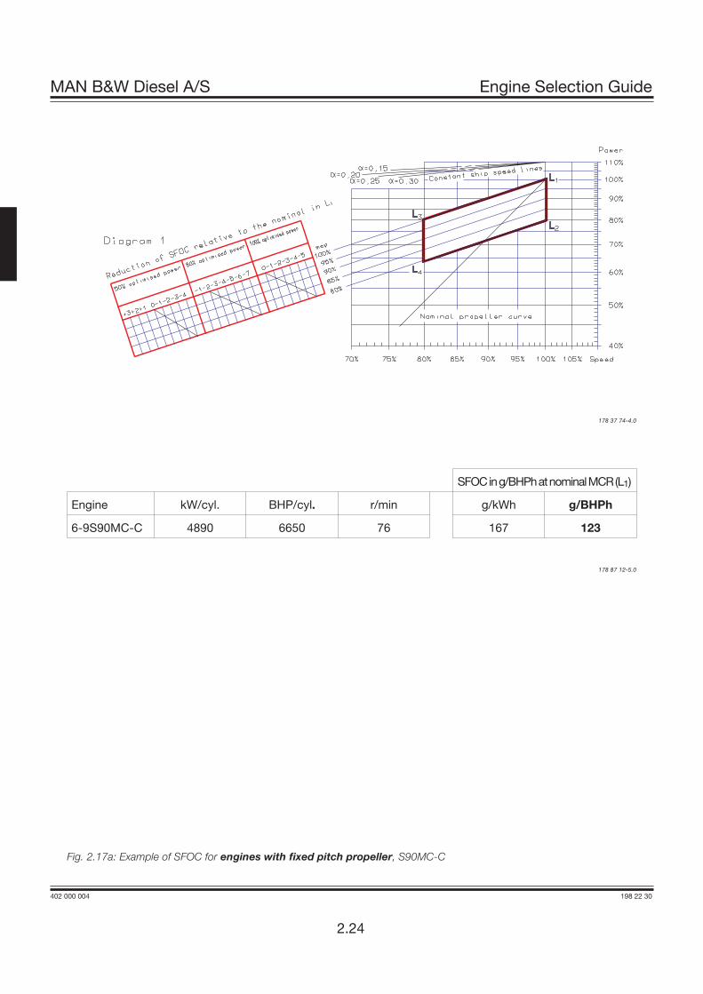
Diagram 1 in the following figures are valid for fixedpitch propeller and constant speed, respectively,shows the reduction in SFOC, relative to the SFOCat nominal rated MCR L1.
The solid lines are valid at 100, 80 and 50% of theoptimised power (O).
The optimising point O is drawn into the above-mentioned Diagram 1. A straight line along theconstant mep curves (parallel to L1-L3) is drawnthrough the optimising point O. The line intersec-tions of the solid lines and the oblique lines indi-cate the reduction in specific fuel oil consumptionat 100%, 80% and 50% of the optimised power,related to the SFOC stated for the nominal MCR(L1) rating at the actually available engine version.
The SFOC curve for an engine with conventionalturbocharger is identical to that for an engine withhigh efficiency turbocharger, but located at 2g/BHPh higher level.
In Fig. 2.24 an example of the calculated SFOCcurves are shown on Diagram 2, valid for two al-ternative engine ratings: O1 = 100% M andO2 = 85%M for a 6S70MC-C with VIT fuel pumps.
MAN B&W Diesel A/S Engine Selection Guide
402 000 004 198 22 30
2.21

402 000 004 198 22 30
MAN B&W Diesel A/S Engine Selection Guide
SFOCing/BHPhatnominalMCR(L1)
Engine kW/cyl. BHP/cyl. r/min g/kWh g/BHPh
6-12K98MC 5720 7780 94 171 126
6-12K98MC-C 5710 7760 104 171 126
Data optimising point (O):
Power: 100% of (O) BHP
Speed: 100% of (O) r/min
SFOC found: g/BHPh
These figures are valid both for engines with fixed pitch propeller and for engines running at constant speed.
178 87 11-3.0
Fig. 2.16a: SFOC for engines with fixed pitch propeller, K98MC and K98MC-C
2.22
178 44 22-7.1

MAN B&W Diesel A/S Engine Selection Guide
402 000 004 198 22 30
2.23
178 44 22-7.0
Fig. 2.16b: SFOC for engines with constant speed,
178 44 22-7.1
402 000 004 198 22 30
MAN B&W Diesel A/S Engine Selection Guide
2.24
SFOCing/BHPhatnominalMCR(L1)
Engine kW/cyl. BHP/cyl. r/min g/kWh g/BHPh
6-9S90MC-C 4890 6650 76 167 123
178 37 74-4.0
Fig. 2.17a: Example of SFOC for engines with fixed pitch propeller, S90MC-C
178 87 12-5.0

MAN B&W Diesel A/S Engine Selection Guide
402 000 004 198 22 30
Fig. 2.17b: Example of SFOC for engines with constant speed,
178 37 75-6.0
178 11 68-5.0
2.25

402 000 004 198 22 30
MAN B&W Diesel A/S Engine Selection Guide
Fig. 2.18a: Example of SFOC for engines with fixed pitch propeller,
SFOCing/BHPhatnominalMCR(L1)
)Engine kW/cyl. BHP/cyl. r/min g/kWh g/BHPh
6-12K90MC-C 4560 6210 104 171 126
6-12K80MC-C 3610 4900 104 171 126
Data optimising point (O):
Power: 100% of (O) BHP
Speed: 100% of (O) r/min
SFOC: g/BHPh
178 06 87-7.0
2.26
178 39 35-1.0
178 87 13-7.0

MAN B&W Diesel A/S Engine Selection Guide
402 000 004 198 22 30
Fig. 2.18b: Example of SFOC for engines with constant speed,
178 06 89-0.0
2.27
178 44 22-7.1

402 000 004 198 22 30
MAN B&W Diesel A/S Engine Selection Guide
Fig. 2.19a: Example of SFOC for engines with fixed pitch propeller
178 43 63-9.0
178 15 92-3.0
2.28
SFOC in g/BHPh at nominal MCR (L1)
TurbochargersHigh efficiency Conventional
Engine kW/cyl. BHP/cyl. r/min g/kWh g/BHPh g/kWh g/BHPh6-12L90MC-C 4890 6650 83 167 1234-12K90MC 4570 6220 94 171 1266-8S80MC-C 3880 5280 76 167 1234-9S80MC 3840 5220 79 167 1234-12L80MC 3640 4940 93 174 1284-8S70MC-C* 3105 4220 91 169 124 171 1264-8S70MC 2810 3820 91 169 124 171 1264-8L70MC 2830 3845 108 174 1284-8S60MC-C* 2255 3070 105 170 125 173 1274-8S60MC 2040 2780 105 170 125 173 1274-8L60MC 1920 2600 123 171 126 174 1284-8S50MC-C* 1580 2145 127 171 126 174 1284-8S50MC 1430 1940 127 171 126 174 1284-8L50MC 1330 1810 148 173 127 175 1294-12L42MC* 995 1355 176 177 130
* Note: Engines without VIT fuel pumps have to be optimised at the specified MCR power
These figures are valid both for engines with fixed pitch propeller and for engines running at constant speed.
Data optimising point (O):
Power: 100% of (O) BHP
Speed: 100% of (O) r/min
SFOC found: g/BHPh

MAN B&W Diesel A/S Engine Selection Guide
402 000 004 198 22 30
Fig. 2.19b: Example of SFOC for engines with constant speed
178 43 63-9.0
178 15 91-1.0
2.29

402 000 004 198 22 30
MAN B&W Diesel A/S Engine Selection Guide
These figures are valid both for engines with fixed pitch propeller and for engines running at constant speed.
Fig. 2.20a: Example of SFOC for engines with fixed pitch propeller
178 06 88-9.0
SFOC in g/BHPh at nominal MCR (L1)
Engine kW/cyl. BHP/cyl. r/min g/kWh g/BHPh
4-8S46MC-C 1310 1785 129 174 128
4-12S42MC 1080 1470 136 177 130
4-12S35MC 740 1010 173 178 131
4-12L35MC 650 880 210 177 130
4-12S26MC 400 545 250 179 132
Data optimising point (O):
Power: 100% of (O) BHP
Speed: 100% of (O) r/min
2.30
178 87 15-0.0
Specified MCR (M) = optimised point (O)

MAN B&W Diesel A/S Engine Selection Guide
402 000 004 198 22 30
Fig. 2.20b: Example of SFOC for engines with constant speed
178 43 63-9.0
2.31
178 06 90-0.0
Specified MCR (M) = optimised point (O)

402 000 004 198 22 30
MAN B&W Diesel A/S Engine Selection Guide
Fig. 2.21: Example of SFOC for 6S70MC-C with fixed pitch propeller, high efficiency turbocharger and VIT fuel pumps
178 43 67-6.0
178 15 88-8.0
2.32
Data at nominal MCR (L1): 6S70MC-C Data of optimising point (O) O1 O2
100% Power:100% Speed:High efficiency turbocharger:
25,32091
124
BHPr/ming/BHPh
Power: 100% of OSpeed: 100% of OSFOC found:
21,000 BHP81.9 r/min
122.1 g/BHPh
17,850 BHP77.4 r/min
119.7 g/BHPh
Note: Engines without VIT fuel pumps have to be optimised at the specified MCR power
O1: Optimised in MO2: Optimised at 85% of power MPoint 3: is 80% of O2 = 0.80 x 85% of M = 68% MPoint 4: is 50% of O2 = 0.50 x 85% of M = 42.5% M
178 43 66-4.0

Fuel Consumption at an Arbitrary Load
Once the engine has been optimised in point O,shown on this Fig., the specific fuel oil consumptionin an arbitrary point S1, S2 or S3 can be estimatedbased on the SFOC in points “1" and ”2".
These SFOC values can be calculated by using thegraphs for fixed pitch propeller (curve I) and for theconstant speed (curve II), obtaining the SFOC inpoints 1 and 2, respectively.
Then the SFOC for point S1 can be calculated as aninterpolation between the SFOC in points “1" and”2", and for point S3 as an extrapolation.
The SFOC curve through points S2, to the left ofpoint 1, is symmetrical about point 1, i.e. at speedslower than that of point 1, the SFOC will also in-crease.
The above-mentioned method provides only an ap-proximate figure. A more precise indication of theexpected SFOC at any load can be calculated byusing our computer program. This is a service whichis available to our customers on request.
MAN B&W Diesel A/S Engine Selection Guide
402 000 004 198 22 30
Fig. 2.22: SFOC at an arbitrary load
178 05 32-0.1
2.33