2. about on-site stormwater management devices
TRANSCRIPT

Section 2: About on-site stormwater management devices
On-Site Stormwater Management Guideline, October 2004 New Zealand Water Environment Research Foundation
1
2. About on-site stormwater management devices
In this section: 2.1 On-site devices defined in brief 2.2 Evolution of on-site stormwater technologies 2.3 On-site devices described and devices covered by this guideline 2.4 Other useful resources 2.5 Rapid reference: a quick guide to the devices in this guideline 2.6 References Where particular caution needs to be exercised, the following format is used:
Cautionary advice is given in a box next to a red flag.
2.1 On-site devices defined in brief On-site stormwater management devices typically: • receive stormwater runoff from small-scale impervious areas such as individual lots • aim to temporarily detain runoff and meet one or more of the following objectives:
o flow control, for example by throttling the peak discharge o water quality control, for example by filtering out sediment that may contain
contaminants o volume control by water re-use o provide disposal, for example infiltration trench
In contrast with the conventional approach of discharging stormwater direct to large-scale piped systems, on-site devices reflect modern practice for at-source controls that better reflect the sustainability outcomes summarised in section 1. Section 2.2 backgrounds the evolution of on-site devices. In the context of sustainability, on-site devices are an integral part of water sensitive urban design/development (WSUD) or low impact design (LID), that protects and incorporates natural site features into erosion and sediment control and stormwater management plans. On-site devices should, where practicable, be used with water sensitive urban design/development and low impact design and, as outlined in section 1, within the context of integrated catchment and asset management plans to: • protect or enhance water quality and preserve natural habitat and ecosystems • mimic natural drainage regimes (including groundwater recharge where appropriate) • adopt more sustainable forms of development • reduce the amount and form of hard infrastructure and impervious surfaces • improve visual and physical amenity values
Section 2: About on-site stormwater management devices
On-Site Stormwater Management Guideline, October 2004 New Zealand Water Environment Research Foundation
2
On-site devices can be used: • in small-scale developments on individual lots, where the assignment of operation and
maintenance obligations to individual owners and occupiers normally dictates their applicability
• in multi-unit developments, where body corporates offer a potentially feasible operation and maintenance arrangement
• in new (greenfield) developments • in infill or redevelopment (brownfield) developments • where the protection or enhancement of natural features is required to be maximised • where peak flow reduction is sought, for example to avoid overtaxing built or natural
stormwater infrastructure that is undersized to cope with additional impervious areas • where the at-source removal of contaminants in stormwater is desirable, for example where:
o larger-scale catchment water quality control devices are not feasible, and/or where o there is an impetus to protect the natural values of the receiving waters
A key issue with on-site devices is the ownership and responsibility for operation and maintenance. Continuing maintenance of on-site devices may become a major issue, as many owners or subsequent owners of the development may have only very limited knowledge of them. Resolution of this issue is crucial for the successful implementation of on-site devices and their ongoing effectiveness. See Appendix D.
2.2 Evolution of on-site stormwater technologies Built-up areas need to be drained to remove surface water. Traditionally, this was done using underground pipes designed on a quantity imperative, to prevent flooding by conveying water away as quickly as possible. However, this approach concentrates the flow and can lead to problems such as erosion and flooding elsewhere in the catchment, while current trends of intensifying urban development are generating runoff that exceeds the pipes’ design capacity. More recently, emphasis has been devoted to reducing both the concentration of flow and the discharging of the pollutants in stormwater from urban areas into watercourses or groundwater. These goals can be partly met through source-control, or on-site stormwater management, which involves detaining the runoff so as to trap contaminants at source and/or reduce flooding. Over the past 20 years on-site stormwater management has evolved to now become the norm in many big cities throughout North America and Europe. In the USA it developed in the mid-1980s and was mainly concerned with water quality control. In other countries, its focus from the outset was more on water quantity control, although most quantity-oriented on-site methods will also provide a degree of water quality benefit. Probably the best known examples of on-site devices are rain tanks (although these are not common in North American practice), rain gardens, wetlands and swales. In practice, the rate of evolution of new on-site devices is quite slow, although proprietary on-site stormwater treatment devices continue to come onto the market. Current evolutionary trends are more in the application than the design of on-site practices. In the USA in particular, choices tend to be dictated by local climatic conditions.
Section 2: About on-site stormwater management devices
On-Site Stormwater Management Guideline, October 2004 New Zealand Water Environment Research Foundation
3
For water quantity control, it is increasingly common to set performance targets that match the greenfield standard, even in infill applications where public stormwater assets have been designed to meet the developed urban impervious area standard. In the USA, pipelines are also being daylighted by removing the pipe and restoring the former natural watercourse. The greenfield standard is even applied to central city commercial area in some cases, such as Calgary City in Alberta, Canada, where buildings meet the standard by storing rainfall on their flat roofs and releasing it at the greenfield rate. The State of Maryland in the USA has bad experiences with roof storage and abandoned it (E. Shaver, pers. comm). New trends in on-site applications include:
• on-site devices, originally focused on domestic applications, are being re-engineered for industrial sites, with device selection targeted to particular industrial hazards
• detention tanks, particularly below-ground tanks, are falling from favour because of the difficulty of ensuring proper maintenance. In their place, rain tanks incorporating both stormwater detention and re-use are becoming popular, though there are potential public health issues with using water from them, especially in densely urbanised areas
• use of on-site devices to manage road runoff by means including street rain gardens (for example as sunken roundabouts) and pervious paving is growing in the USA
• roof gardens or green roofs are increasingly used, especially in commercial areas where their aesthetic merits can come to the fore, though their uptake is slow, perhaps due to waterproofing issues and the expense of the load-bearing construction
• in areas with soakage, on-site infiltration devices sometimes combined with detention devices are increasingly used, and can help to recharge aquifers as well as take pressure off the piped stormwater system. The use of on-site devices to treat runoff before discharge to ground is beneficial, as it helps prevent soakage systems failing by clogging as a result of sedimentation of the surface of the infiltration medium
• the initial enthusiasm for proprietary mechanical on-site devices has ebbed somewhat, due to the relatively high operating and maintenance costs, together with lack of understanding and data on their performance
Effective operation and maintenance is crucial for long-term satisfactory performance of on-site devices. Various models promote this, such as: • traditional: voluntary regime, with guidance given and backed by random
inspections • obligatory (manual): owners are required to have their on-site device
serviced at designated intervals, with servicing certification submitted to the controlling authority
• obligatory (high-tech): in installing an on-site device, the owner agrees to contract out maintenance to the controlling authority, which equips the serviceperson with a notebook computer that has the site and device details; on completing the service, details are logged in and downloaded to the controlling authority’s database
There is more on O&M in Table 3.11, Section 4 and Appendix D.
Section 2: About on-site stormwater management devices
On-Site Stormwater Management Guideline, October 2004 New Zealand Water Environment Research Foundation
4
Comparable trends in on-site design standards and guidelines include:
• traditionally, on-site devices have been designed to meet the required performance standard in the design storm condition through hydrograph analysis. New trends include: o continuous simulation of long pluviographic sequences, through which the performance
in the full range of storm temporal patterns can be assessed o simulating the performance of multiple on-site devices distributed throughout a
catchment (the traditional approach does not account for this or for the effects of different times of concentration in different parts of the downstream receiving network)
• similarly, design for water quality has traditionally used empirical methods such as a water quality volume, as in ARC TP10, but modelling is increasingly able to quantify the treatment process, including selective treatment of site-specific contaminants
• the trend in on-site guidance documentation is away from the ‘text-book’ approach of compiling all known information, because it can be easily accessed through the Internet. Instead, step-by-step design processes are often put in place to ensure appropriate use of devices
2.3 On-site devices described On-site devices typically incorporate the following general features:
• an inlet that receives stormwater from the roof and/or impervious areas of the site
• a detention zone that temporarily stores runoff, thereby attenuating the peak flow
• a treatment zone that may comprise sand or soil that is designed to filter out contaminants (it is important to also provide detention storage for these, as the filtration rate is typically slow)
• a disposal facility, which may be by way of: o connection to the public stormwater system – road kerb/channel, pipe, watercourse o dispersal over the ground surface o discharge to ground by soakage, applicable in areas with good soakage characteristics
such as gravels, sandy loams or fractured volcanic rocks 1
In hydrologic terms, on-site devices flatten the runoff hydrograph in much the same way as reservoir routing. This is shown in Figure 2.1, which shows the first flush of a storm being stored and released on the tail of the hydrograph. Table 2.1 lists the on-site devices covered by this guideline. In the absence of a universally-accepted naming convention, the generic names in common usage in New Zealand have been adopted. However, alternative names are also listed to facilitate overseas literature searches. Section 3 provides guidance on selecting the appropriate on-site device or devices for a particular application.
In summary, criteria for selecting any particular device include:
• objectives: treatment and/or flow attenuation
• source of stormwater to be fed to device: roof and/or site runoff
• site characteristics: topography, soils, building layout, etc
1 This guideline addresses disposal to ground by soakage by way of describing where this disposal method may be applicable, the range of disposal options and references covering the design of soakage disposal systems

Section 2: About on-site stormwater management devices
On-Site Stormwater Management Guideline, October 2004 New Zealand Water Environment Research Foundation
5
• physical device requirements: space, landscaping, landscaping and aesthetics
• technical availability: for example in remote areas it may be difficult to access to those with the necessary skills and abilities to install and/or maintain particular systems, making their use less technically feasible
• number, ownership and operation/maintenance of devices
• costs and other implementation issues including permits and consents
Figure 2.1 First flush storage and release on the tail of the hydrograph

Section 2: About on-site stormwater management devices
On-Site Stormwater Management Guideline, October 2004 New Zealand Water Environment Research Foundation
6
Table 2.1 On-site devices covered by this guideline Device name Alternative
name(s) Section Description
Step-by-step design procedure
Filter Treatment wall 4.1
Device to store and treat stormwater by filtration. The sand filter is the best known example, but the genre also includes custom-designed/proprietary filters and the use of a variety of filtration media
Infiltration trench Bio-filtration system, infiltra-tion gallery
4.2 Gravel-filled trench (can be constructed underneath a swale)
Rain garden Bio-retention system 4.3
Device constructed within in-situ soil where treatment is achieved by flow through a sand/soil medium
Stormwater planter 4.4
Rain garden-type device, but specifically for collection of roof water only and to provide flow detention for peak flow reduction
Rain tank Dual-use tank 4.5 Above ground tanks catching roof runoff only and incorporating stormwater detention and re-use zones
Swale / filter strip Grass filter 4.6
Devices where treatment is achieved via shallow surface flow channels achieving treatment by surface flow
Wetland Marsh 4.7 Constructed shallow pond with intensive plantings
Guidance notes
Detention tank OSD or on-site detention tank 5.1
Constructed tanks used for flow control and /or treatment, including custom built and proprietary devices
Pond Retarding basin 5.2 Includes ponds dug or created by a dam and used for flow detention and treatment
Roof garden Green roof or eco-roof 5.3 A planted and drained soil medium constructed on
the roof of a building
Roof gutters 5.4 Use of enlarged roof gutters and similar devices to detain stormwater or peak flow control on roofs
Depression storage Retarding basin 5.5
Ponding on specially-designed source areas to detain stormwater for peak flow control (where applicable, can dispose of stormwater to ground)
Permeable pavement
Permeable or pervious paving 5.6 Pavement systems that allow significant infiltration
of runoff and percolation into underlying strata
Treatment trench/ Rock filter
Often associated with permeable pavement
5.7 An excavated trench backfilled with stone or scoria media providing treatment before disposal to a piped reticulation system or to surface water
Catchpit insert Catchpit filter 5.8 A filter insert used to remove gross pollutants and particulate bound contaminants
Gross pollutant traps, litter traps, hydrodynamic separator
5.9
Includes devices that intercept some combination of the following: rubbish, grit, coarse sediment, oil and litter. Includes custom built gross pollutant traps, sediment traps, oil and grit traps, rubbish traps and proprietary units
Oil and water separator 5.10 Used only for removal of hydrocarbons
Section 2: About on-site stormwater management devices
On-Site Stormwater Management Guideline, October 2004 New Zealand Water Environment Research Foundation
7
2.4 Other useful resources • Auckland City Council. (2002). On-site stormwater management manual (henceforth
referred to as ACC 2002)
• Auckland Regional Council. (2000). Low impact design manual for the Auckland Region. ARC Technical Publication No. 124 (henceforth referred to as ARC TP124)
• Auckland Regional Council. (2003). Stormwater treatment devices: design guideline manual. ARC Technical Publication No. 10 (henceforth referred to as ARC TP10)
• Christchurch City Council. (2003). Waterways, wetlands and drainage guide (henceforth referred to as CCC, 2003)
• Rodney District Council and the Auckland Regional Council. (2000). DRAFT Management of stormwater in countryside living zones (rural and town): a toolbox of methods
• Standards New Zealand. (2001). New Zealand handbook: Subdivision for people and the environment. (SNZ HB 44:2001)
• Waitakere City Council. (2002). Countryside and foothills stormwater management code of practice
2.4.2 Selected electronic reference material New Zealand sources include:
• Stormwater directory of New Zealand. (2004) www.stormwaterdirectory.org.nz
• Auckland Regional Council. (2000) Low impact design manual for the Auckland Region. Technical Publication No. 124 (ARC TP124) www.arc.govt.nz/arc/environment/water/low-impact-design.cfm
• Auckland Regional Council. (2003) Stormwater treatment devices – design guideline manual. ARC TP10. http://www.arc.govt.nz/arc/index.cfm?34C9C2A8-1BCF-4AA1-91AF-CC49CFE4A80C
• Auckland City Council. (2002). On-site stormwater management manual. www.aucklandcity.govt.nz
International sources include:
• International stormwater BMP database: http://www.bmpdatabase.org/ .This contains an extensive compilation of the latest international best management practice for on-site stormwater management devices, as summarised in Table 2.2
• City of Portland: Stormwater management manual www.cleanrivers-pdx.org
• Maryland (USA): Stormwater design manual, volumes I & II (Effective October 2000). http://www.mde.state.md.us/Programs/WaterPrograms/SedimentandStormwater/stormwater_design/index.asp
• Western Australia: A major review of the Manual for managing urban stormwater quality in Western Australia (Water and Rivers Commission, 1998) is under way. The Interim Position Statement: Urban Stormwater Management in WA - Principles and Objectives was released in February 2003 to provide the Department's policy on urban stormwater management while the Stormwater Management Manual for Western Australia (2004) is being produced. Once completed, the Stormwater management manual for Western Australia (2004) will replace the Manual for Managing Urban Stormwater Quality in WA and the Interim Position Statement: Urban Stormwater Management in WA - Principles and Objectives as the key guiding document for stormwater management in Western Australia. http://www.wrc.wa.gov.au/protect/stormwater/smm.htm
Section 2: About on-site stormwater management devices
On-Site Stormwater Management Guideline, October 2004 New Zealand Water Environment Research Foundation
8
• Washington State Dept of Ecology: Stormwater management manual for Western Washington www.ecy.wa.gov
• Upper Parramatta River Catchment Trust: On-site detention handbook www.upperparariver.nsw.gov.au
• Drainage & Irrigation Dept, Malaysia: Draft stormwater management manual http://agrolink.moa.my/did/river/stormwater/toc.htm
Appendix B contains a list of all the references used in this document, including Internet URLs wherever possible.
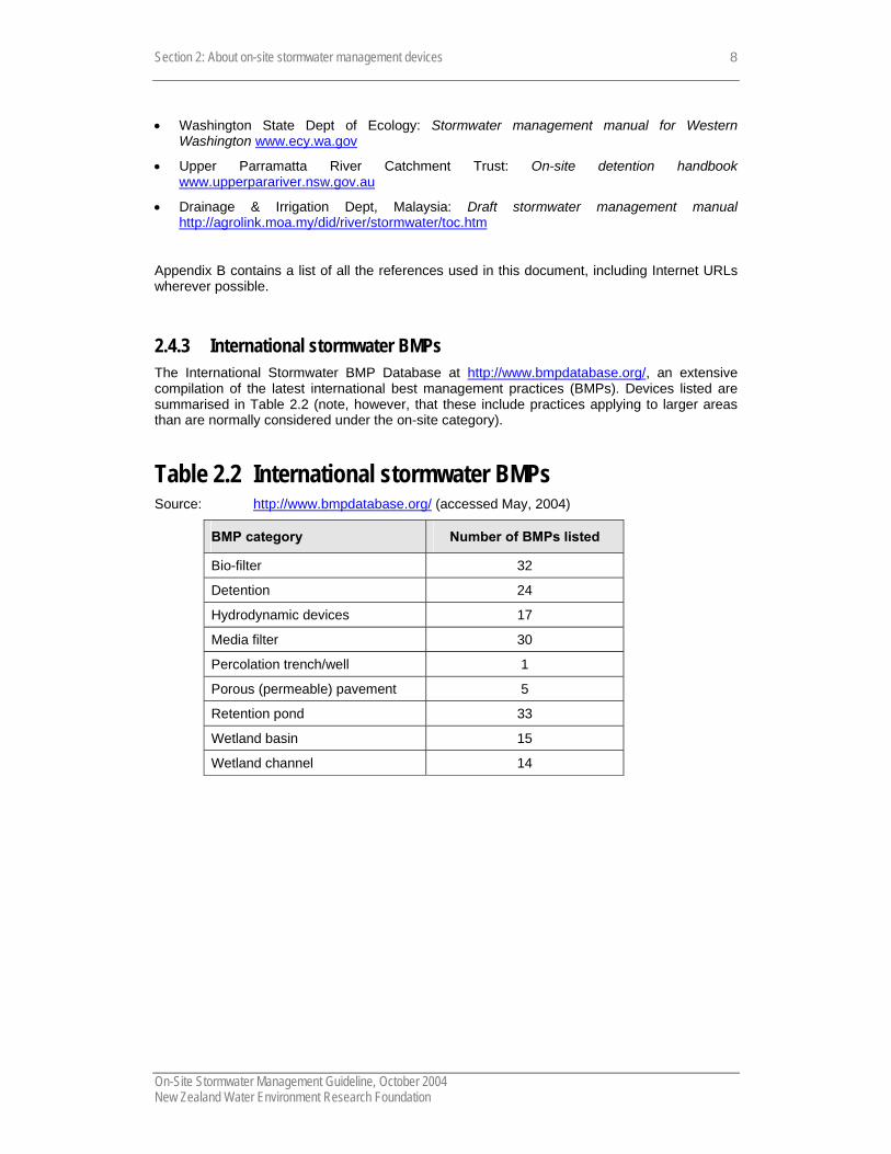
2.4.3 International stormwater BMPs The International Stormwater BMP Database at http://www.bmpdatabase.org/, an extensive compilation of the latest international best management practices (BMPs). Devices listed are summarised in Table 2.2 (note, however, that these include practices applying to larger areas than are normally considered under the on-site category).
Table 2.2 International stormwater BMPs Source: http://www.bmpdatabase.org/ (accessed May, 2004)
BMP category Number of BMPs listed
Bio-filter 32
Detention 24
Hydrodynamic devices 17
Media filter 30
Percolation trench/well 1
Porous (permeable) pavement 5
Retention pond 33
Wetland basin 15
Wetland channel 14
Section 2: Rapid reference: a quick guide to the devices in this guideline
On-Site Stormwater Management Guideline, October 2004 New Zealand Water Environment Research Foundation
9
2.5 Rapid reference: a quick guide to the devices in this guideline
The following devices are briefly overviewed in this subsection:
• filter • infiltration trench • rain garden • stormwater planter • rain tank (dual-use tank) • swale/ filter strip • wetland • detention tank
• pond • roof garden (eco-roof) • roof gutters • depression storage • permeable pavement • treatment trench/ rock filter • catchpit insert • gross pollutant traps • oil and water separator
Key to symbols: Primary function/s n good effectiveness of device for primary function listed Ο not effective, or partial effectiveness of device for primary function listed
Applications, attributes, do’s and don’ts • positive attributes • things to pay particular attention to if using this device • don’ts: things not to do or use the device for
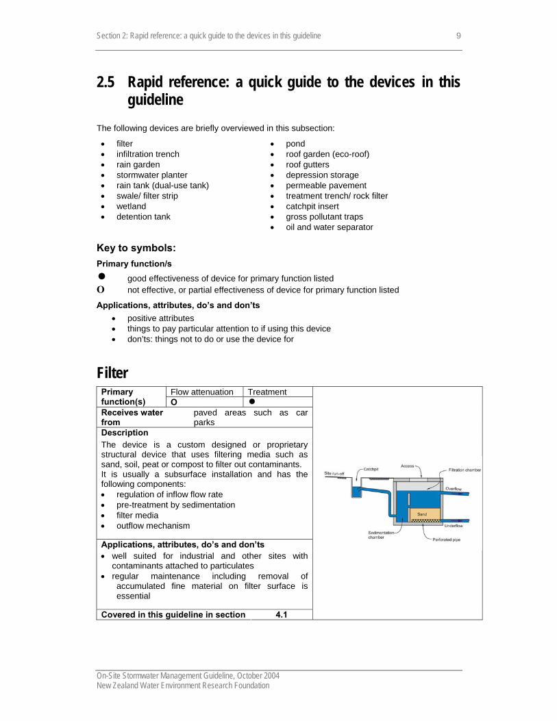
Filter Flow attenuation Treatment Primary
function(s) Ο n Receives water from
paved areas such as car parks
Description The device is a custom designed or proprietary structural device that uses filtering media such as sand, soil, peat or compost to filter out contaminants. It is usually a subsurface installation and has the following components: • regulation of inflow flow rate • pre-treatment by sedimentation • filter media • outflow mechanism
Applications, attributes, do’s and don’ts • well suited for industrial and other sites with
contaminants attached to particulates • regular maintenance including removal of
accumulated fine material on filter surface is essential
Covered in this guideline in section 4.1

Section 2: Rapid reference: a quick guide to the devices in this guideline
On-Site Stormwater Management Guideline, October 2004 New Zealand Water Environment Research Foundation
10
Infiltration trench
Treatment Primary function(s)
Disposal n
Receives water from
paved areas such as car parks
Description The device is a trench containing gravel and provides treatment and disposal of stormwater. Some treatment is provided by gravel in the trench but most treatment is provided by adjoining soil Applications, attributes, do’s and don’ts • requires permeable soils and appropriate
topography to avoid slope instability • care need to avoid contamination of groundwater • requires pretreatment to reduce sediment loads
and avoid blockage well suited for commercial, some industrial and
other sites requires a small footprint
Covered in this guideline in section 4.2
Rain garden Flow attenuation Treatment Primary
function(s) Ο n
Receives water from
paved areas such as driveways, car parks
Description: This device, also known as bioretention area, is an in-ground filter with the upper surface of the filter medium exposed to allow infiltration of collected stormwater ponded on it. The filter medium is a specially selected soil/sand mix with a surface mulch or organic layer. Small, shallow-rooting plants protect this medium (the ‘soil medium’ and provide some evapotranspiration. Applications, attributes, do’s and don’ts can be incorporated within domestic or commercial
landscaped areas can serve as an attractive landscaping feature
Covered in this guideline in section 4.3
Section 2: Rapid reference: a quick guide to the devices in this guideline
On-Site Stormwater Management Guideline, October 2004 New Zealand Water Environment Research Foundation
11
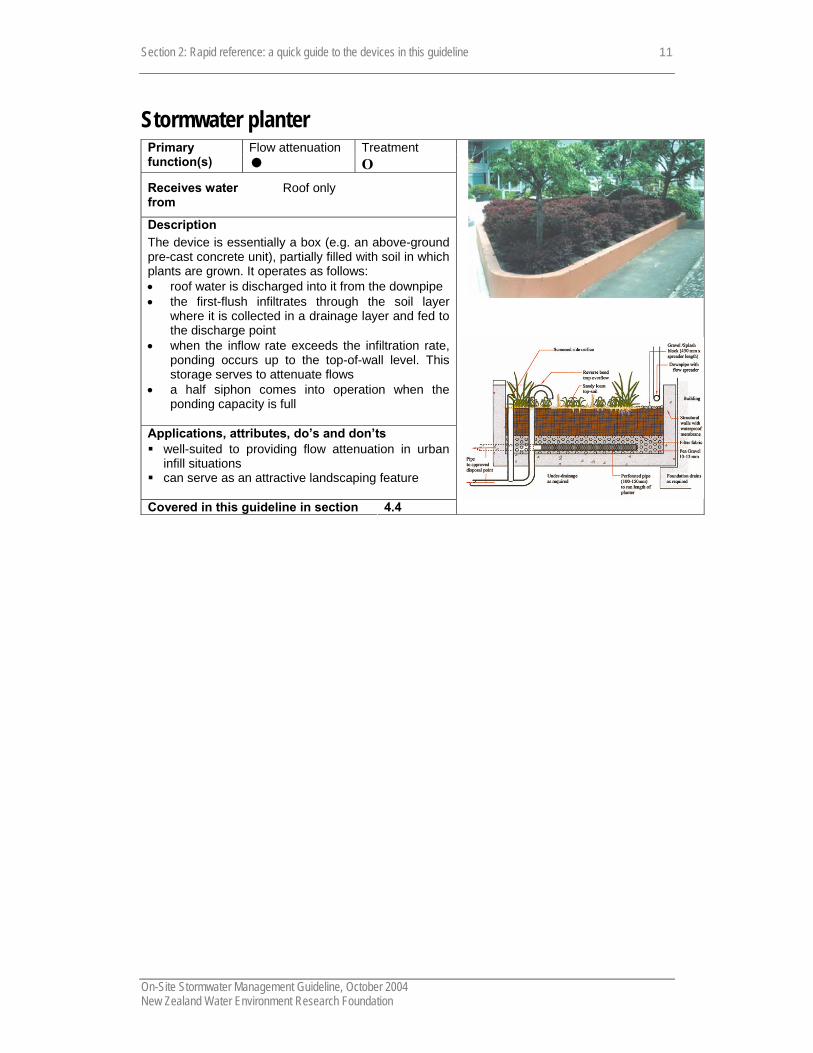
Stormwater planter Flow attenuation Treatment Primary
function(s) n Ο
Receives water from
Roof only
Description The device is essentially a box (e.g. an above-ground pre-cast concrete unit), partially filled with soil in which plants are grown. It operates as follows: • roof water is discharged into it from the downpipe • the first-flush infiltrates through the soil layer
where it is collected in a drainage layer and fed to the discharge point
• when the inflow rate exceeds the infiltration rate, ponding occurs up to the top-of-wall level. This storage serves to attenuate flows
• a half siphon comes into operation when the ponding capacity is full
Applications, attributes, do’s and don’ts well-suited to providing flow attenuation in urban
infill situations can serve as an attractive landscaping feature
Covered in this guideline in section 4.4

Section 2: Rapid reference: a quick guide to the devices in this guideline
On-Site Stormwater Management Guideline, October 2004 New Zealand Water Environment Research Foundation
12
Rain tank (dual-use tank) Flow attenuation Treatment Primary
function(s) n Ο Receives water from
Roof / other impervious area
Description Tank (concrete, plastic or steel), receiving and storing roof runoff. Features include: • an upper temporary storage zone, sized to detain
runoff to meet the flow attenuation target. The outflow rate is controlled by an orifice at the bottom of the temporary storage zone
• below this is a permanent storage or re-use zone, from which water is drawn for household uses (e.g. non-potable uses such as outdoor watering, toilet flushing and laundry)
• tanks are normally located above-ground (or partially buried to allow gravity inflow)
• provision is generally made for topping-up the tank in dry periods from the mains supply; a backflow preventer is required to avoid cross-contamination
• a first flush diverter is typically provided to limit the contaminants reaching the tank
Applications, attributes, do’s and don’ts • where buried, concrete tanks must be crack-proof
to avoid the ingress of contaminants • close attention must be paid to ensuring that the
plumbing from the tank meets NZS 3500:5:2000 • the local water and/or wastewater utility may have
regulations affecting the avoidance of charges arising from water re-use
re-use is often very cost-effective, especially where a tank is required in any event for flow control purposes
the re-use benefit, in parallel with the public health imperative, is seen as encouraging sound maintenance practices
Covered in this guideline in section 4.5

Section 2: Rapid reference: a quick guide to the devices in this guideline
On-Site Stormwater Management Guideline, October 2004 New Zealand Water Environment Research Foundation
13
Swale / filter strip Flow attenuation Treatment Primary
function(s) Ο n Receives water from
paved areas such as driveways, car parks
Description These devices use vegetation in conjunction with slow and shallow depth of flow. Contaminants are removed by a combination of filtration, adsorption and biological uptake. Vegetation also decreases flow velocity and allows settlement of particulates.
Applications, attributes, do’s and don’ts can be incorporated within car parks or within road
median strips can serve as an attractive landscaping feature
Covered in this guideline in section 4.6
Swale at car park at North Harbour Stadium
Wetland
Flow attenuation Treatment Primary function(s) n n Receives water from
paved areas such as driveways, car parks, industrial yards, multi-lot developments
Description Shallow ponds that incorporate dense vegetation. Purposes and befits are: • flood protection • extended detention for stream channel protection • water quality improvement • landscape benefit • provision of wildlife habitat Applications, attributes, do’s and don’ts • appropriate for larger sites –generally over 1 ha provides multi-purpose quality and peak flow
reduction can provide aesthetic benefit
Covered in this guideline in section 4.7
Wetland at Unitec campus Auckland
Section 2: Rapid reference: a quick guide to the devices in this guideline
On-Site Stormwater Management Guideline, October 2004 New Zealand Water Environment Research Foundation
14
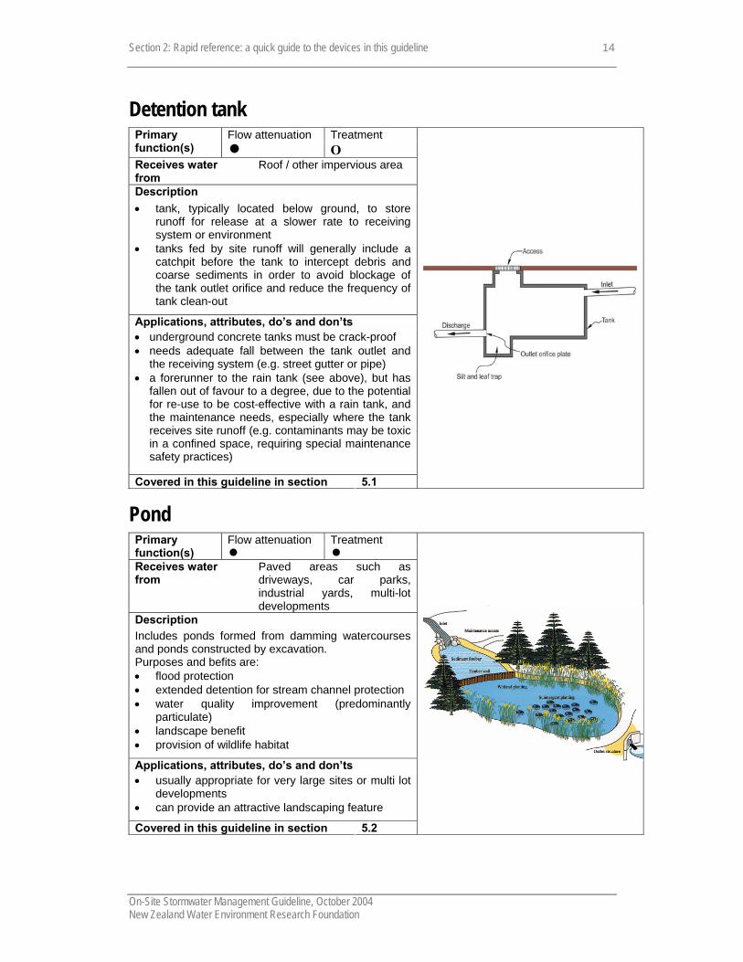
Detention tank Flow attenuation Treatment Primary
function(s) n Ο Receives water from
Roof / other impervious area
Description • tank, typically located below ground, to store
runoff for release at a slower rate to receiving system or environment
• tanks fed by site runoff will generally include a catchpit before the tank to intercept debris and coarse sediments in order to avoid blockage of the tank outlet orifice and reduce the frequency of tank clean-out
Applications, attributes, do’s and don’ts • underground concrete tanks must be crack-proof • needs adequate fall between the tank outlet and
the receiving system (e.g. street gutter or pipe) • a forerunner to the rain tank (see above), but has
fallen out of favour to a degree, due to the potential for re-use to be cost-effective with a rain tank, and the maintenance needs, especially where the tank receives site runoff (e.g. contaminants may be toxic in a confined space, requiring special maintenance safety practices)
Covered in this guideline in section 5.1
Pond Flow attenuation Treatment Primary
function(s) n n Receives water from
Paved areas such as driveways, car parks, industrial yards, multi-lot developments
Description Includes ponds formed from damming watercourses and ponds constructed by excavation. Purposes and befits are: • flood protection • extended detention for stream channel protection • water quality improvement (predominantly
particulate) • landscape benefit • provision of wildlife habitat
Applications, attributes, do’s and don’ts • usually appropriate for very large sites or multi lot
developments • can provide an attractive landscaping feature
Covered in this guideline in section 5.2

Section 2: Rapid reference: a quick guide to the devices in this guideline
On-Site Stormwater Management Guideline, October 2004 New Zealand Water Environment Research Foundation
15
Roof garden (eco-roof) Flow attenuation Treatment Primary
function(s) n n Receives water from
Roof only
Description Used in place of a conventional roof to achieve quantity and quality control. Features include: • roof structure overlain by a waterproof membrane • soil, with underlying drainage system (proprietary) • supports vegetation • flow attenuation is achieved by evapotranspiration
and soil capture • contaminants are removed by filtration through the
soil Applications, attributes, do’s and don’ts • careful structural and waterproofing detailing is
needed to avoid leakage into building • appropriate plant selection to withstand a range of
climatic conditions is vital; plants may require irrigation in dry periods
• garden requires regular maintenance can serve as an attractive and novel landscaping
feature, for example where it is visible from an adjacent deck or roof
Covered in this guideline in section 5.3
Example of roof garden, USA
Roof gutters Flow attenuation Treatment Primary
function(s) n Ο Receives water from
Roof only
Description • over-sized gutters/spouting • outlet flow throttling by orifices provides flow
attenuation Applications, attributes, do’s and don’ts • significant storage needs to be provided in the
gutters to achieve anything more than minor flow attenuation
• careful structural and waterproofing detailing is needed to avoid leakage into building
• correct sizing of outlet orifices and maintenance to avoid blocking is critical
Covered in this guideline in section 5.4

Section 2: Rapid reference: a quick guide to the devices in this guideline
On-Site Stormwater Management Guideline, October 2004 New Zealand Water Environment Research Foundation
16
Depression storage Flow attenuation Treatment Primary
function(s) n Ο? Receives water from
Roof / general impervious areas
Description • natural or artificial permeable area capable of
detaining runoff, such as a depression in the lawn or a low lying car park area
• provides temporary storage to attenuate runoff • can provide some treatment, particularly for
grasses areas • stormwater disposal can be by soakage for
vegetated areas in permeable soils or via a low level piped outlet
Applications, attributes, do’s and don’ts • a simple device, but may require a sizeable area
which will retain water for some time after a storm • do not site where it creates a flood risk to adjacent
buildings/properties
Covered in this guideline in section 5.5

Section 2: Rapid reference: a quick guide to the devices in this guideline
On-Site Stormwater Management Guideline, October 2004 New Zealand Water Environment Research Foundation
17
Permeable pavement Flow attenuation Treatment Primary
function(s) n n Receives water from
Car park or yard areas
Description • a pavement that is specifically designed to
facilitate and maximise infiltration of rainfall through the pavement for stormwater benefit.
• final disposal generally is by infiltration to underlying ground but they can be used where final disposal is via a piped reticulation or to surface water.
• includes o porous concrete and porous asphalt o plastic modular systems o interlocking concrete paving blocks (including
modular blocks and lattice blocks)
Applications, attributes, do’s and don’ts • primarily parking areas, low volume roadways or
driveways • particular care is need in the design of the
pavement foundations with respect to effects of infiltration, traffic loads, the nature of the subgrade and pavement durability
• there are potentially significant issues with respect to blinding of the surfaces of permeable pavements with fine material. This may in some situations be able to be prevented or minimised by ongoing maintenance, for example using suction devices. May require removal and replacement of pavers for renovation
Covered in this guideline in section 5.6
Car park at Parr’s Park, Auckland
Section 2: Rapid reference: a quick guide to the devices in this guideline
On-Site Stormwater Management Guideline, October 2004 New Zealand Water Environment Research Foundation
18
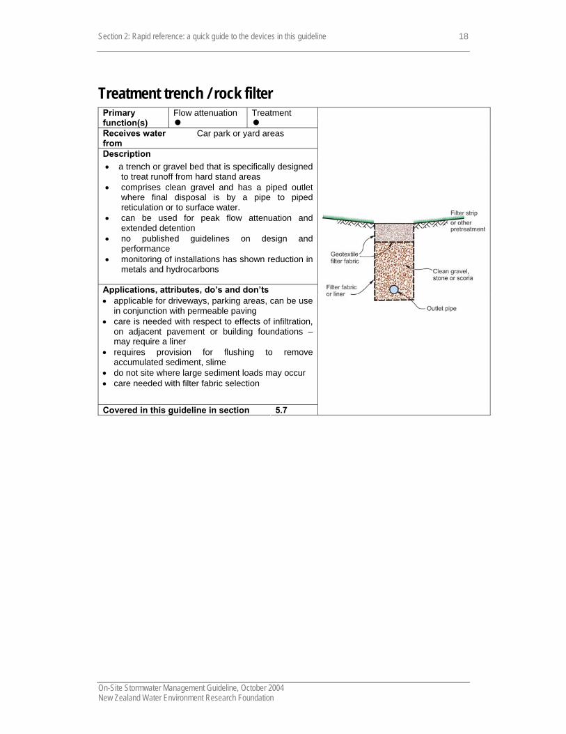
Treatment trench / rock filter Flow attenuation Treatment Primary
function(s) n n Receives water from
Car park or yard areas
Description • a trench or gravel bed that is specifically designed
to treat runoff from hard stand areas • comprises clean gravel and has a piped outlet
where final disposal is by a pipe to piped reticulation or to surface water.
• can be used for peak flow attenuation and extended detention
• no published guidelines on design and performance
• monitoring of installations has shown reduction in metals and hydrocarbons
Applications, attributes, do’s and don’ts • applicable for driveways, parking areas, can be use
in conjunction with permeable paving • care is needed with respect to effects of infiltration,
on adjacent pavement or building foundations –may require a liner
• requires provision for flushing to remove accumulated sediment, slime
• do not site where large sediment loads may occur • care needed with filter fabric selection
Covered in this guideline in section 5.7
Section 2: Rapid reference: a quick guide to the devices in this guideline
On-Site Stormwater Management Guideline, October 2004 New Zealand Water Environment Research Foundation
19
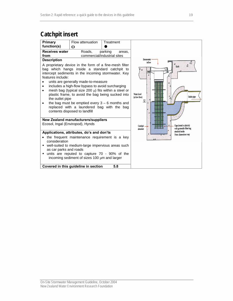
Catchpit insert Flow attenuation Treatment Primary
function(s) Ο n Receives water from
Roads, parking areas, commercial/industrial sites
Description A proprietary device in the form of a fine-mesh filter bag which hangs inside a standard catchpit to intercept sediments in the incoming stormwater. Key features include: • units are generally made-to-measure • includes a high-flow bypass to avoid surcharging • mesh bag (typical size 200 µ) fits within a steel or
plastic frame, to avoid the bag being sucked into the outlet pipe
• the bag must be emptied every 3 – 6 months and replaced with a laundered bag with the bag contents disposed to landfill
New Zealand manufacturers/suppliers Ecosol, Ingal (Enviropod), Hynds
Applications, attributes, do’s and don’ts • the frequent maintenance requirement is a key
consideration well-suited to medium-large impervious areas such
as car parks and roads units are reputed to capture 70 - 90% of the
incoming sediment of sizes 100 µm and larger
Covered in this guideline in section 5.8

Section 2: Rapid reference: a quick guide to the devices in this guideline
On-Site Stormwater Management Guideline, October 2004 New Zealand Water Environment Research Foundation
20
Gross pollutant traps Flow attenuation Treatment Primary
function(s) Ο n Receives water from
Roads, yards
Description Key features include: • remove coarse sediment, litter and debris,
sometimes oil • include specifically designed proprietary devices • includes litter traps, hydrodynamic devices
New Zealand manufacturers/suppliers • Ecosol New Zealand Ltd www.ecosol.com.au • Hynds Environmental www.hynds.co.nz • Ingal Environmental Services
www.ingalenviro.com • Bisleys Environmental Ltd www.bisleys.net
Applications, attributes, do’s and don’ts Often used at the head of a treatment train, for
example to prevent coarse sediment entering a wetland or other stormwater treatment device
• intended to remove only coarse sediment, litter and debris, unlikely to remove fine sediments or soluble contaminants
• can be retrofitted into existing development sites • ongoing operation and maintenance, including
sediment removal can be expensive Covered in this guideline in section 5.9

Section 2: Rapid reference: a quick guide to the devices in this guideline
On-Site Stormwater Management Guideline, October 2004 New Zealand Water Environment Research Foundation
21
Oil and water separator Flow attenuation Treatment Primary
function(s) Ο n Receives water from
Paved areas prone to hydrocarbon contamination, for example service stations
Description Primarily aimed at removing oil from stormwater at sites where hydrocarbon products are handled and small spills regularly occur on paved surfaces. Can include specifically designed devices as well as proprietary devices. New Zealand manufacturers/suppliers • Alpha Environmental (Nelson) • Ecosol www.ecosol.com.au • Hynds Environmental Systems Ltd
www.hynds.co.nz • Maskell Productions www.maskell.co.nz • Westfalia Separator NZ Ltd www.westfalia-
separator.com
Covered in this guideline in section 5.10
API Oil and Water separator
Section 2: About on-site stormwater management devices
On-Site Stormwater Management Guideline, October 2004 New Zealand Water Environment Research Foundation
22
2.6 References Publications Auckland Regional Council. 1998. Large lot stormwater management design approach. TP92.
Auckland Regional Council. 2003. Stormwater treatment devices design guidelines manual. ARC Technical Publication No.10 (ARC TP10). http://www.arc.govt.nz/arc/index.cfm?34C9C2A8-1BCF-4AA1-91AF-CC49CFE4A80C.
Auckland City Council. 2002. On-site stormwater management programme. (ACC 2002).
Auckland Regional Council. 2000. Low impact design manual for the Auckland Region, Technical Publication No. 124 (ARC TP124) www.arc.govt.nz/arc/environment/water/low-impact-design.cfm.
Christchurch City Council. 2003. Waterways, wetlands and drainage guide. (CCC, 2003).
New Zealand Water and Wastes Association (NZWWA). 2001. Needs analysis and scoping survey for stormwater quality management. Survey and report prepared by Environment and Business Group. (NZWWA, 2001).
Rodney District Council and the Auckland Regional Council. 2000. DRAFT Management of stormwater in countryside living zones (rural and town): a toolbox of methods.
Standards New Zealand. 2001. New Zealand Handbook: Subdivision for people and the environment. SNZ HB 44:2001.
Waitakere City Council. 2002. Countryside and foothills stormwater management code of practice.
Web - based resources Auckland City Council. 2002. On-site stormwater management manual (2002).
www.aucklandcity.govt.nz.
City of Portland. Stormwater management manual. www.cleanrivers-pdx.org.
Drainage & Irrigation Dept, Malaysia. Draft stormwater management manual. http://agrolink.moa.my/did/river/stormwater/toc.htm.
International stormwater BMP database. http://www.bmpdatabase.org/.
Maryland (USA): Stormwater design manual, Volumes I & II (Effective October 2000). http://www.mde.state.md.us/Programs/WaterPrograms/SedimentandStormwater/stormwater_design/index.asp
New Zealand Water Environment Research Foundation. Stormwater directory of New Zealand. 2004. www.stormwaterdirectory.org.nz.
Upper Parramatta River Catchment Trust. On-site detention handbook. www.upperparariver.nsw.gov.au.
Washington State Dept of Ecology. Stormwater management manual for Western Washington. www.ecy.wa.gov.
Western Australia: Manual for managing urban stormwater quality in Western Australia (Water and Rivers Commission, 1998) (currently under review) http://www.wrc.wa.gov.au/protect/stormwater/smm.htm