shdshinieurope.com/.../insideout/standard_hopper_drying-shd_manual.pdf · table 2-23:electrical...
TRANSCRIPT

SHD “Standard” Hopper Dryer
Date: Jun, 2015
Version: Ver.B


3(101)
Content
1. General Description .....................................................................................9
1.1 Coding Principle ....................................................................................10
1.2 Feature..................................................................................................10
1.3 Technical Specifications........................................................................12
1.3.1 External Dimensions....................................................................12
1.3.2 Specification ................................................................................13
1.4 Safety Regulations ................................................................................15
1.4.1 Safety Signs and Labels ..............................................................15
1.4.2 Signs and Labels .........................................................................16
1.5 Exemption Clause.................................................................................16
2. Structure Characteristics and Working Principle ....................................17
2.1 Working Principle ..................................................................................17
2.2 Drawing and Parts List ..........................................................................18
2.2.1 Assembly Drawing (SHD-25~75).................................................18
2.2.2 Parts List (SHD-25~75) ...............................................................19
2.2.3 Assembly Drawing (SHD-100~150).............................................20
2.2.4 Parts List (SHD-100~150) ...........................................................21
2.2.5 Assembly Drawing (SHD-12&200~300) ......................................22
2.2.6 Parts List (SHD-12&200~300) .....................................................23
2.2.7 Assembly Drawing (SHD-400~600).............................................24
2.2.8 Parts List (SHD-400~600) ...........................................................25
2.2.9 Assembly Drawing (SHD-800~1000)...........................................26
2.2.10 Parts List (SHD-800~1000) ...................................................27
2.3 Circuit Diagram .....................................................................................28
2.3.1 Power, Diameter, Current (SHD-12~300 400V) ..........................28
2.3.2 Electrical Diagram(SHD-12~300 400V) .......................................29
2.3.3 Electrical Components Layout (SHD-12~300 400V) ...................32
2.3.4 Bill of Electrical Parts(SHD-12~300 400V) ..................................34
2.3.5 Power, Diameter, Current (SHD-400~1000 400V) ......................41
2.3.6 Electrical Diagram(SHD-400~1000 400V) ...................................42
2.3.7 Electrical Components Layout (SHD-400~1000 400V)................44
2.3.8 Bill of Electrical Parts(SHD-400~1000 400V) ..............................45

4(101)
2.3.9 Power, Diameter, Current (SHD-EH 400V)..................................50
2.3.10 Electrical Diagram(SHD-EH 400V)........................................51
2.3.11 Electrical Components Layout (SHD-EH 400V) ....................53
2.3.12 Bill of Electrical Parts(SHD-EH 400V) ...................................54
2.3.13 Power, Diameter, Current (SHD-12~300 230V) ....................60
2.3.14 Electrical Diagram (SHD-12~300 230V)................................61
2.3.15 Electrical Components Layout (SHD-12~300 230V) .............64
2.3.16 Electrical Components List (SHD-12~300 230V) ..................66
2.3.17 Power, Diameter, Current (SHD-400~1000 230V) ................73
2.3.18 Electrical Diagram (SHD-400~1000 230V)............................74
2.3.19 Electrical Components Layout (SHD-400~1000 230V) .........76
2.3.20 Electrical Components List (SHD-400~1000 230V) ..............77
2.3.21 Electrical Diagram(SHD-12EH 230V)....................................82
2.3.22 Electrical Components Layout (SHD-12EH 230V) ................84
2.3.23 Electrical Components List (SHD-12EH 230V)......................85
3. Installation and Debugging........................................................................86
3.1 Direct Installation...................................................................................86
3.2 Floor Stand Installation .........................................................................87
3.3 Connecting the Power Source ..............................................................87
3.4 The Hopper Dryer Test .........................................................................87
3.5 Installation of the Options......................................................................88
3.5.1 Installation of Air-Exhaust Cyclone Dust Collector /Air-Exhaust Filter 88
3.5.2 Suction Box Installation ...............................................................89
3.5.3 Blower Inlet Filter Installation.......................................................89
3.5.4 Hot Air Recycler Installation.........................................................90
4. Operation Guide .........................................................................................91
4.1 Control Panel ........................................................................................91
4.1.1 Panel Operation...........................................................................91
4.1.2 Setting Temperature....................................................................91
4.2 Control Panel with Dryer .......................................................................93
4.2.1 Panel Operation...........................................................................94
4.2.2 Timer Setting ...............................................................................94
4.3 Control Panel(SHD-400~1000) .............................................................95

5(101)
4.3.1 Panel Operation...........................................................................95
4.3.2 Temperature Setting....................................................................95
4.3.3 Temperature Lock .......................................................................95
4.3.4 PID Setting ..................................................................................96
4.3.5 Intermittent Operation Setting......................................................97
4.3.6 One-week Timing Setting ............................................................97
4.3.7 Communication Setting (optional functions) ................................97
4.3.8 Operation Flow ............................................................................99
4.3.9 Wrong Codes Remark ...............................................................100
5. Maintenance and Repair ..........................................................................101
5.1 Blower .................................................................................................101
6. Troubleshooting .......................................................................................101
Table Index
Table 1-1:Specification................................................................................... 13
Table 1-2:Dryer drying capacity(kg/hr)(Selection guide) ................................ 14
Table 2-1:Parts List (SHD-25~75).................................................................. 19
Table 2-2:Parts List (SHD-100~150).............................................................. 21
Table 2-3:Parts List (SHD-12&200~300)........................................................ 23
Table 2-4:Parts List (SHD-400~600).............................................................. 25
Table 2-5:Parts List (SHD-800~1000)............................................................ 27
Table 2-6:Electrical components list (SHD-12 400V) ..................................... 34
Table 2-7:Electrical components list (SHD-25 400V) ..................................... 35
Table 2-8:Electrical components list (SHD-50 400V) ..................................... 36
Table 2-9:Electrical components list (SHD-75 400V) ..................................... 37
Table 2-10:Electrical components list (SHD-100/150 400V) .......................... 38
Table 2-11:Electrical components list (SHD-200 400V) ................................. 39
Table 2-12:Electrical components list (SHD-300 400V) ................................. 40
Table 2-13:Electrical components list (SHD-400 400V) ................................. 45
Table 2-14:Electrical components list (SHD-500 400V) ................................. 46
Table 2-15:Electrical components list (SHD-600 400V) ................................. 47
Table 2-16:Electrical components list (SHD-800 400V) ................................. 48
Table 2-17:Electrical components list (SHD-1000 400V) ............................... 49

6(101)
Table 2-18:Electrical components list (SHD-12EH 400V) .............................. 54
Table 2-19:Electrical components list (SHD-25EH 400V) .............................. 55
Table 2-20:Electrical components list (SHD-50EH 400V) .............................. 56
Table 2-21:Electrical components list (SHD-75EH 400V) .............................. 57
Table 2-22:Electrical components list (SHD-100EH 400V) ............................ 58
Table 2-23:Electrical components list (SHD-300EH 400V) ............................ 59
Table 2-24:Electrical components list (SHD-12 230V) ................................... 66
Table 2-25:Electrical components list (SHD-25 230V) ................................... 67
Table 2-26:Electrical components list (SHD-50 230V) ................................... 68
Table 2-27:Electrical components list (SHD-75 230V) ................................... 69
Table 2-28:Electrical components list (SHD-100/150 230V) .......................... 70
Table 2-29:Electrical components list (SHD-200 230V) ................................. 71
Table 2-30:Electrical components list (SHD-300 230V) ................................. 72
Table 2-31:Electrical components list (SHD-400 230V) ................................. 77
Table 2-32:Electrical components list (SHD-500 230V) ................................. 78
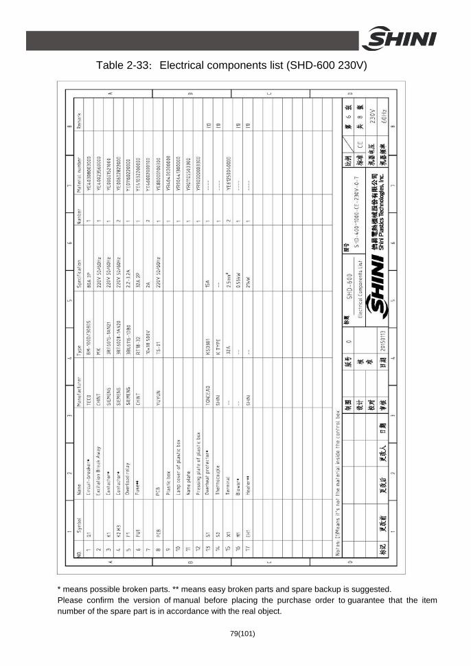
Table 2-33:Electrical components list (SHD-600 230V) ................................. 79
Table 2-34:Electrical components list (SHD-800 230V) ................................. 80
Table 2-35:Electrical components list (SHD-1000 230V) ............................... 81
Table 2-36:Electrical components list (SHD-12EH 230V) .............................. 85
Picture Index
Picture 1-1:External dimensions..................................................................... 12
Picture 2-1:Working principle ......................................................................... 17
Picture 2-2:Assembly drawing SHD-25~75.................................................... 18
Picture 2-3:Assembly drawing SHD-100~150................................................ 20
Picture 2-4:Assembly drawing SHD-12&200~300.......................................... 22
Picture 2-5:Assembly drawing SHD-400~600................................................ 24
Picture 2-6:Assembly drawing SHD-800~1000.............................................. 26
Picture 2-7:Electrical diagram 1 (SHD-12~300 400V).................................... 29
Picture 2-8:Electrical diagram 2 (SHD-12~300 400V).................................... 30
Picture 2-9:Electrical diagram 3 (SHD-12T~300T 400V) ............................... 31
Picture 2-10:Electrical components layout 1(SHD-12~300 400V).................. 32
Picture 2-11:Electrical components layout 2 (SHD-12T~300T 400V) ............ 33
7(101)
Picture 2-12:Electrical diagram 1 (SHD-400~1000 400V).............................. 42
Picture 2-13:Electrical diagram 2 (SHD-400~1000 400V).............................. 43
Picture 2-14:Electrical components layout (SHD-400~1000 400V)................ 44
Picture 2-15:Electrical diagram 1 (SHD-EH 400V)......................................... 51
Picture 2-16:Electrical diagram 2 (SHD-EH 400V)......................................... 52
Picture 2-17:Electrical components layout (SHD-EH 400V)........................... 53
Picture 2-18:Electrical diagram 1 (12~300 230V)........................................... 61
Picture 2-19:Electrical diagram 2 (SHD-12~300 230V).................................. 62
Picture 2-20:Electrical diagram 3 (SHD-12T~300T 230V) ............................. 63
Picture 2-21:Electrical components layout 1(SHD-12~300 230V).................. 64
Picture 2-22:Electrical components layout 2 (SHD-12T~300T 230V) ............ 65
Picture 2-23:Electrical diagram 1 (SHD-400~1000 230V).............................. 74
Picture 2-24:Electrical diagram 2 (SHD-400~1000 230V).............................. 75
Picture 2-25:Electrical components layout (SHD-400~1000 230V)................ 76
Picture 2-26:Electrical diagram 1 (SHD-12EH 230V)..................................... 82
Picture 2-27:Electrical diagram 2 (SHD-12EH 230V)..................................... 83
Picture 2-28:Electrical components layout (SHD-12EH 230V)....................... 84
Picture 3-1:Direct installation ......................................................................... 86
Picture 3-2:Floor stand installation................................................................. 87
Picture 3-3:Blower.......................................................................................... 88
Picture 3-4: Left : Air-exhaust elbow of dryer ................................................ 88
Picture 3-5:European suction box .................................................................. 89
Picture 3-6:Shut-off suction box ..................................................................... 89
Picture 3-7:Right:AIF blower inlet filter ........................................................ 90
Picture 3-8:Hot air recycler............................................................................. 90
Picture 4-1:Control panel ............................................................................... 91
Picture 4-2:Temperature controller................................................................. 91
Picture 4-3:Lead sheet fuse ........................................................................... 93
Picture 4-4:Overheating protector .................................................................. 93
Picture 4-5:Control panel (with timer)............................................................. 93
Picture 4-6:Timer............................................................................................ 94
Picture 4-7:Control Panel(SHD-400~1000).................................................... 95

8(101)
9(101)
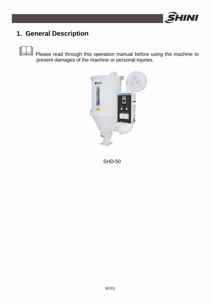
1. General Description
Please read through this operation manual before using the machine to prevent damages of the machine or personal injuries.
SHD-50

10(101)
1.1 Coding Principle
Note* M=Magnetic Base(SHD-300 and models below) I=Double Insulated Layers T=Timer EH=Standard DT=Microprocessor with timer SL=RS485 Communication Function
1.2 Feature 1) Standard configuration ü Adopt hot air diffuser to gain an even hot air flow to improve drying efficiency. ü Hot air inlet elbow design can prevent dust piling up at bottom of the pipe
heaters so as to avoid burning. ü All material contact surfaces are made of stainless steel to eliminate material
contamination. ü Hopper separated from its base, ensuring convenient cleaning. ü For SHD-12~300, adopt proportional deviation display thermostat for
accurate temperature control. ü All series are equipped with exposed power switch. ü For SHD-25~150, heater pipes are connected by aluminum sheets and other
models are equipped with temperature protection to prevent heater pipe from damaging by blower faults.
ü Overheat tripping can automatically cut off power when drying temperature exceeds set deviation value.
ü Adopts heat-insulated blower to prolong blower lifespan. ü For SHD-100 and models above, standard equipped with 24-hour auto
start/stop timer. ü For SHD-400~1000, adopt PCB controller for easy operation.
2) Accessory option

11(101)
ü Micro computer control panel (with timer) and heat-preservation hopper are optional for each model.
ü Cyclone dust separator, exhaust air filter, magnetic base and blower inlet filter are optional.
ü Hot air recycler, suction box, hopper magnetic, N type floor stand and storage hopper are optional.
ü For SHD-75 and models below, 24-hour auto start/stop timer is optional. ü SHD-12~SHD-200 optional high-temp. model is avaliable, the max. temp.
can reach 180℃. ü Insulated hopper is optional.
All service work should be carried out by a person with technical training or corresponding professional experience. The manual contains instructions for both handling and servicing. Chapter 5, which contains service instructions intended for service engineers. Other chapters contain instructions for the daily operator.
Any modifications of the machine must be approved by SHINI in order to avoid personal injury and damage to machine. We shall not be liable for any damage caused by unauthorized change of the machine.
Our company provides excellent after-sales service. Should you have any problem during using the machine, please contact the company or the local vendor.
Headquarter and Taipei factory: Tel: (886) 2 2680 9119 Shini Plastics Technologies (Dongguan), Inc: Tel: (86) 769 8111 6600 Shini Plastics Technologies India Pvt.Ltd.: Tel: (91) 250 3021 166

12(101)
1.3 Technical Specifications 1.3.1 External Dimensions
Picture 1-1:External dimensions

13(101)
1.3.2 Specification Table 1-1:Specification
SHD 12 25 50 75 100 150 200 300 400 500 600 800 1000
Ver. B A A A A A A A A A A B B
HeaterPower(kW) 2.2 / 3*
3 / 3.3*
3.9 / 4.2*
4.2 / 4.8*
6 / 6.6*
6.6 / 7.2*
12 / 15*
15 18 19.5 21 24 32
BlowerPower (50 kW)
0.05 0.12 0.12 0.12 0.12 0.12 0.18 0.18 0.18 0.18 0.55 1.1 1.1
Loading Capacity (kg)
12 25 50 75 100 150 200 300 400 500 600 800 1000
H(mm) 790 1015 1145 1240 1340 1580 1580 1980 2170 2350 2570 2760 3060
H1(mm) 690 925 1045 1150 1340 1605 1332 1432 1900 1900 2075 2300 2530
H2(mm) 317 410 380 475 470 470 550 550 838 838 838 1010 1010
H3(mm) 370 460 520 620 725 970 975 1220 1220 1400 1545 540 540
H4(mm) 106 194 206 208 233 233 184 184 334 334 334 1550 1845
H5(mm) 115 150 150 150 158 158 158 158 283 283 283 283 283
W(mm) 660 725 840 900 955 955 1230 1230 1365 1365 1365 1420 1420
D(mm) 360 405 490 550 605 605 770 770 915 915 950 600 600
D1(mm) 130 158 158 158 238 238 238 238 345 345 345 345 345
W1(mm) 130 148 148 148 238 238 238 238 345 345 345 345 345
ΦA(mm) 325 385 470 530 595 595 750 750 910 910 910 960 960
ΦB(mm) 55 55 55 55 90 90 90 90 105 105 105 105 105
Weight (kg) 35 40 45 55 70 75 100 120 165 170 240 280 300
Note: 1) Install 24hr timer, add "T" at the back of the model.SHD-100 and models above standard equipped with the timer.
2) Additional note of "M" will be added to SHD-300 and below models, the bases of which are changed to be magnetic bases.
3) Change into double insulated layer, add "I" at the back of the model 4) Upon request, it can be built to comply with worldwide electrical safety standards . 5) Above loading capacity is based on pellet material of 0.65kg/L in bulk density and 3~5mm in diameter.
6) “*”Stands for high-temp.model, add "H" at the end of model code. 7) Power: 3Φ, 230/400/460/575VAC, 50/60Hz.

14(101)
Table 1-2:Dryer drying capacity(kg/hr)(Selection guide) D
ryin
g Te
mp.
80℃
80℃
80℃
80℃
80℃
75℃
75℃
75℃
80℃
75℃
-
120℃
70℃
Dry
ing
Tim
e
0.75
hrs
0.75
hrs
0.75
hrs
1hrs
1hrs
4hrs
5hrs
7hrs
2.5h
rs
2.25
hrs
1.5h
rs
3hrs
1.25
hrs
1000
1000
1000
1000
750
400
200
165
110
330
375
430
200
510
800
800
800
800
600
320
160
130
90
365
300
380
160
445
600
600
600
600
440
240
120
100
70
200
220
330
120
380
500
500
500
500
375
200
100
80
60
165
180
275
105
305
400
400
400
400
300
160
80
65
50
140
150
220
90
250
300
300
300
300
225
120
60
45
35
100
110
160
75
185
200
200
200
200
150
80
35
30
20
60
70
100
40
120
150
150
150
150
115
60
27
22
15
45
52
75
30
90
100
100
100
100
80
40
20
16
10
30
35
50
20
60
75
75
75
75
57
30
13
11
7 22
26
37
15
45
50
50
50
50
38
20
10
8 5 12
17
25
10
30
25
20
20
20
14
8 4 3.2 2 6 6 10
4 12
Mod
el S
HD
12
8 8 8 6 4 2 1.5 1 2.5
2.5 4 1.5 5
Mat
eria
l
Pol
ysty
re
Pol
yeth
ylen
Poly
prop
yren
e
Pol
y st
yren
ce
H·
D
AB
S
Nyl
on 1
1,12
Nyl
on6/
6,6/
10
Nyl
on 6
Acr
ylic
fibe
r
Cel
lulo
se
acet
ate
But
yrat
e
Polyc
arbo
nate
Rig
id P
VC
Notes:Based on relative humidity 65% with ambient temperature of 20℃,moisure content after drying can be
0.2% ro less.
15(101)
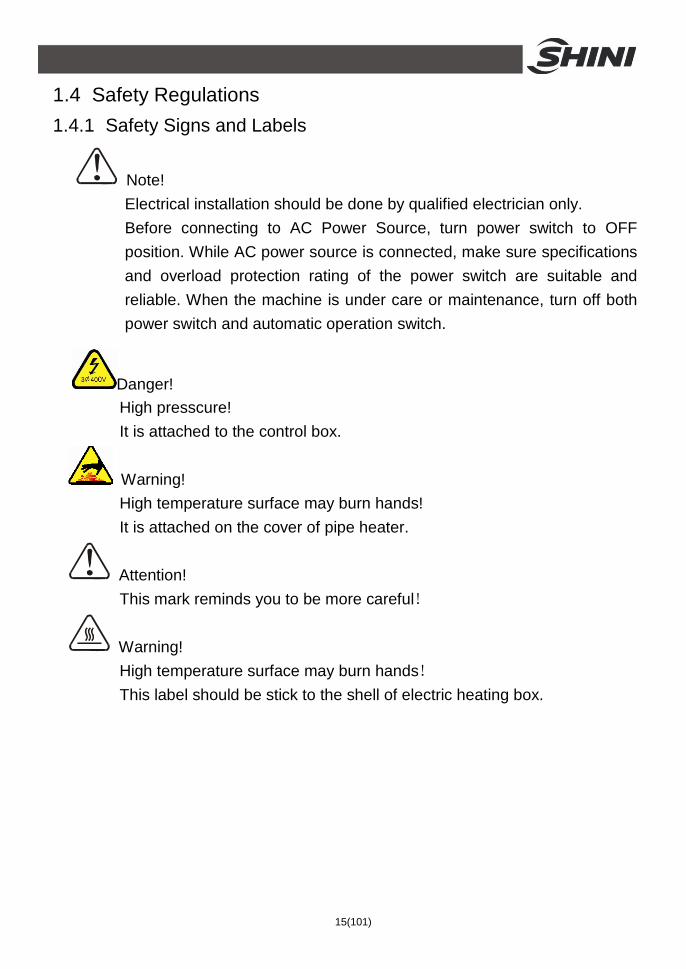
1.4 Safety Regulations 1.4.1 Safety Signs and Labels
Note! Electrical installation should be done by qualified electrician only. Before connecting to AC Power Source, turn power switch to OFF position. While AC power source is connected, make sure specifications and overload protection rating of the power switch are suitable and reliable. When the machine is under care or maintenance, turn off both power switch and automatic operation switch.
Danger! High presscure! It is attached to the control box.
Warning! High temperature surface may burn hands! It is attached on the cover of pipe heater.
Attention! This mark reminds you to be more careful!
Warning! High temperature surface may burn hands! This label should be stick to the shell of electric heating box.

16(101)
1.4.2 Signs and Labels
Protection device activates when overheat occurs;after faults are discharged,press blue key to reset and turn on the switch to Restart operation.
Push-and-pull switch for shut-off plate: I: Means "Pull" O: Means "Push"
Regularly clean the filter screen to avoid insufficient drying caused by blocking
1.5 Exemption Clause
The following statements clarify the responsibilities and regulations born by any buyer or user who purchases products and accessories from Shini (including employees and agents). Shini is exempted from liability for any costs, fees, claims and losses caused by reasons below:
1. Any careless or man-made installations, operation and maintenances upon machines without referring to the Manual prior to machine using.
2. Any incidents beyond human reasonable controls, which include man-made vicious or deliberate damages or abnormal power, and machine faults caused by irresistible natural disasters including fire, flood, storm and earthquake.
3. Any operational actions that are not authorized by Shini upon machine, including adding or replacing accessories, dismantling, delivering or repairing.
4. Employing consumables or oil media that are not appointed by Shini.

17(101)
2. Structure Characteristics and Working Principle 2.1 Working Principle
Picture 2-1:Working principle
In the drying process, hot air with constant temperature is blown by the drying blower 2 of SHD into the drying hopper 7 to dry the materials. Moisture will be separated out and taken away by hot air, thus to gain a satisfied drying effect.
Air blown out of blower via hot air pipe 4 became high temperature drying air after being heated. Through shade separator 5 and screen protector 6, hot air can be equably dispersed to the material in storage tank (see picture). Hot air recycler is optional so the air entered drying blower 7 after being filtered by return air will get into the drying blower 2 to form a closed loop circle, which saves electricity.

18(101)
2.2 Drawing and Parts List 2.2.1 Assembly Drawing (SHD-25~75)
Remarks:Please refer to material list 2.2.2 for specific explanation of theArabic numbers in parts drawing.
Picture 2-2:Assembly drawing SHD-25~75

19(101)
2.2.2 Parts List (SHD-25~75) Table 2-1:Parts List (SHD-25~75)
Part NO. NO. Name
SHD-25 SHD-50 SHD-75
1 Control box** BH31002500450 BH31005000750 BH31007500250 2 Hot-air pipe** BA10002500410 BA10005000610 BA10005000610
Pipe heater*(SHD) BH70250300150 BH70500300150 BH70750300050
Pipe heater **(SHD-H) BH70253300010 BH70007500510 BH70754800010 3
Pipe heater **(SHD-EH) YW90000301500 YW90003901500 YW90004200000
4 Blower* BM40002500350 BM40003000250 BM40003000250
5 Storage hopper BK01002500020 BK01005000020 BK01007500020
6 Rear hinge at cover YW06125040000 YW06125040000 YW06125040000
7 Exhaust pipe BA10251000010 BA10251000010 BA10251000010
8 Handle hook YW00251000000 YW00251000000 YW00251000000
9 Handle YW00121000000 YW00121000000 YW00121000000
Hopper cover YW09002500000 YW09005000100 BL01007500020 10
Cover fastener YR10002500100 YR10005000100 YR10010040000 Sight glass YW09000600000 YW09000600000 YW09000600000 Sight glass acryl YR40001200000 YR40001200000 YR40001200000 11 Sight glass Fastener
YR40000600000 YR40000600000 YR40000600000
12 Screen separator** BL01002500620 BL01005001120 BL01007500120 13 Shade separator** BL01002501520 BL01005000320 BL01007500320
14 Rear hinge at hopper YW09125000100 YW09125000100 YW09125000100
Hopper BA10002500210 BA10005000110 BA10007500110 15
Hopper fastener YR10002500200 YR10005000200 YR10010000200
16 Base** BY10050000550 BY10050000550 BY10050000550
17 Star pin YW09085400000 YW09085400000 YW09085400000
Star nut YW09675100000 YW09675100000 YW09675100000 18
Star screw YW09051600100 YW09051600100 YW09051600100 * means possible broken parts. ** means easy broken parts and spare backup is suggested. Please confirm the version of manual before placing the purchase order to guarantee that the item number of the spare part is in accordance with the real object.

20(101)
2.2.3 Assembly Drawing (SHD-100~150)
Remarks:Please refer to material list 2.2.4 for specific explanation of theArabic numbers in parts drawing.
Picture 2-3:Assembly drawing SHD-100~150

21(101)
2.2.4 Parts List (SHD-100~150) Table 2-2:Parts List (SHD-100~150)
Part NO. NO. Name SHD-100 SHD-150
1 Control box* BH31101500350 BH31100001550
2 Hot-air pipe** BA10010000610 BA10010000610
Pipe heater**(SHD) BH70103800050 BH70153800050
Pipe heater**(SHD-H) BH70153800050 BH70150720010 3
Pipe heater**(SHD-EH) YW90000601500 -
4 Blower* BM40004000150 BM40004000150
5 Storage hopper BK01010000020 BK01015000020
6 Rear hinge at cover YW06102000000 YW06102000000
7 Exhaust pipe BA10251000010 BA10251000010
8 Handle hook YW00251000000 YW00251000000
9 Handle YW00121000000 YW00121000000
Hopper cover BL01100700720 BL01100700720 10
Cover fastener YR10010040000 YR10010040000 Sight glass YW09000600000 YW09000600000 Sight glass acryl YR40001200000 YR40001200000 11 Sight glass fastener YR40000600000 YR40000600000
12 Screen separator** BL01010000120 BL01010000120 13 Shade separator** BL01010000320 BL01010000320
14 Rear hinge at hopper YW09102000100 YW09102000100
Hopper BA10010000110 BA10010000110 15
Hopper fastener YR10010000200 YR10010000200
Star nut YW09115600000 YW09115600000 16
Star screw YW09100000000 YW09100000000
17 Star pin YW09085400000 YW09085400000
18 Base** BY10200000050 BY10200000050 * means possible broken parts. ** means easy broken parts and spare backup is suggested. Please confirm the version of manual before placing the purchase order to guarantee that the item number of the spare part is in accordance with the real object.

22(101)
2.2.5 Assembly Drawing (SHD-12&200~300)
Remarks:Please refer to material list 2.2.6 for specific explanation of theArabic numbers in parts drawing.
Picture 2-4:Assembly drawing SHD-12&200~300

23(101)
2.2.6 Parts List (SHD-12&200~300) Table 2-3:Parts List (SHD-12&200~300)
Part NO. NO. Name SHD-12 SHD-200 SHD-300
1 Control box** BH31001200350 BH31020000550 BH31030000950 2 Hot-air pipe** BA10001200610 BA10020000610 BL01030000220
Pipe heater**(SHD) BH70120300150 BH70203800050 BH70303800050
Pipe heater** (SHD-H) BH70120300010 BH70200150010 - 3
Pipe heater *(SHD-EH) YW90122200600 - YW90001501500
4 Blower* BM40001500550 BM40005000150 BM40005000150
5 Rear hinge at cover YW06125040000 YW09102000100 YW0910200010
6 Storage hopper BK01001200020 BK01020000020 BK01030000020
Hopper cover YW09001200300 BW09020000020 BW09020000020 7
Cover fastener YR10002500100 YR10002500200 YR10002500200
8 Exhaust pipe BA10001200110 BA10020000210 BA10020000210
9 Handle hook YW00001200000 YW00251000000 YW00251000000
10 Handle YW00121000000 YW00121000000 YW00121000000 Sight glass YW09000600000 YW09000600000 YW09000600000 Sight glass acryl YR40001200000 YR40001200000 YR40001200000 11 Sight glass fastener YR40000600000 YR40000600000 YR40000600000
12 Screen separator** BL01001200120 BL01020000120 BL01020000120 13 Shade separator** BL01001200320 BL01020000320 BL01020000320
Hopper BA10001200310 BA10020000110 BA10020000110 14
Hopper fastener YR10002500200 YR10002500200 YR10002500200 Star nut YW09675100000 YW09115600000 YW09115600000
15 Star screw YW09051600100 YW09100000000 YW09100000000
16 Star pin YW09084500100 YW09085400000 YW09085400000 17 Base** BY10012000150 BY10200000050 BY10200000050
* means possible broken parts. ** means easy broken parts and spare backup is suggested. Please confirm the version of manual before placing the purchase order to guarantee that the item number of the spare part is in accordance with the real object.

24(101)
2.2.7 Assembly Drawing (SHD-400~600)
Remarks:Please refer to material list 2.2.8for specific explanation of theArabic numbers in parts drawing.
Picture 2-5:Assembly drawing SHD-400~600

25(101)
2.2.8 Parts List (SHD-400~600) Table 2-4:Parts List (SHD-400~600)
Part NO. NO. Name SHD-400 SHD-500 SHD-600
1 Control box** BH31040007550 BH31050007650 BH31060007750
2 Hot-air pipe** BA10001200610 BA10001200610 BL01060000220
3 Pipe heater** BH70403800050 BH70503800050 BH70603800050
4 Blower* BM40005000150 BM40005000150 BM30055000150
5 Rear hinge at cover BW09040000110 BW09040000110 BW09040000110
6 Storage hopper BK01040000020 BK01050000020 BK01060000020
Hopper cover BL01040000720 BL01040000720 BL01040000720 7
Cover fastener YR10002500100 YR10002500100 YR10002500100
8 Exhaust pipe BA10020000210 BA10020000210 BA10020000210
9 Handle hook YW00251000000 YW00251000000 YW00251000000
10 Handle YW00121000000 YW00121000000 YW00121000000 Sight glass YW09000600000 YW09000600000 YW09000600000 Sight glass acryl YR40001200000 YR40001200000 YR40001200000 11 Sight glass fastener YR40000600000 YR40000600000 YR40000600000
12 Screen separator** BL01040000920 BL01040000920 BL01040000920
13 Shade separator** BL01040000320 BL01040000320 BL01040000320
Hopper BA10040000110 BA10040000110 BA10040000110 14
Hopper fastener YR10002500100 YR10002500100 YR10002500100
Star nut YW09115600000 YW09115600000 YW09115600000 15
Star screw YW09100000000 YW09100000000 YW09100000000
16 Star pin YW09085400000 YW09085400000 YW09085400000
17 Base** BY10400000050 BY10400000050 BY10400000050 * means possible broken parts. ** means easy broken parts and spare backup is suggested. Please confirm the version of manual before placing the purchase order to guarantee that the item number of the spare part is in accordance with the real object.

26(101)
2.2.9 Assembly Drawing (SHD-800~1000)
Remarks:Please refer to material list 2.2.10 for specific explanation of theArabic numbers in parts drawing.
Picture 2-6:Assembly drawing SHD-800~1000

27(101)
2.2.10 Parts List (SHD-800~1000) Table 2-5:Parts List (SHD-800~1000)
Part NO. NO. Name SHD-800 SHD-1000
1 Control box** BH31080007850 BH31100007950
2 Blower* BM30113230050 BM30113230050
3 Heating case BH70244000750 BH70324000750
4 Air inlet flange BW21601200010 BW21601200010
Storage hopper BK01080000420 BK01100000420 5
Cover fastener YR10002500200 YR10002500200
6 Exhaust pipe BA10020000210 BA10020000210
7 Down-blow pipe BL01800000020 BL01801042620 Sight glass YW09000600000 YW09000600000 Sight glass acryl YR40001200000 YR40001200000 8 Sight glass fastener YR40000600000 YR40000600000
9 Shade separator** BL01080000010 BL01080000010
Hopper BA10100000010 BA10100000010 10
Hopper fastener YR10002500200 YR10002500200
11 Base** BY10400000050 BY10400000050 * means possible broken parts. ** means easy broken parts and spare backup is suggested. Please confirm the version of manual before placing the purchase order to guarantee that the item number of the spare part is in accordance with the real object.

28(101)
2.3 Circuit Diagram 2.3.1 Power, Diameter, Current (SHD-12~300 400V)
Symbol Model
SHD-12 3.5 1.5 10 - - 1.5 0.05 0.2 1.5 2.2 3.3 SHD-25 4.9 1.5 10 - - 1.5 0.12 0.31 1.5 3.0 4.5
SHD-50 6.4 1.5 10 - - 1.5 0.12 0.31 1.5 3.9 6.0
SHD-75 4.9 1.5 10 - - 1.5 0.12 0.31 1.5 4.2 6.5
SHD-100 9.4 2.5 15 - - 1.5 0.12 0.46 1.5 6.0 9.0
SHD-150 9.4 2.5 15 - - 1.5 0.12 0.46 1.5 6.0 9.0
SHD-200 18.5 4.0 25 - - 1.5 0.18 0.64 4.0 12 18
SHD-300 23 4.0 32 - - 1.5 0.18 0.64 4.0 15 22.5
Total current Power cable diameter
Rated current of circuit breakers Drying blower loader
Settings for drying blower loader Blower cable diameter
Drying blower power Drying blower current
Wire diameter of heater Heater power
Heater current

29(101)
2.3.2 Electrical Diagram(SHD-12~300 400V)
Picture 2-7:Electrical diagram 1 (SHD-12~300 400V)

30(101)
Picture 2-8:Electrical diagram 2 (SHD-12~300 400V)

31(101)
Picture 2-9:Electrical diagram 3 (SHD-12T~300T 400V)

32(101)
2.3.3 Electrical Components Layout (SHD-12~300 400V)
Picture 2-10:Electrical components layout 1(SHD-12~300 400V)

33(101)
Picture 2-11:Electrical components layout 2 (SHD-12T~300T 400V)

34(101)
2.3.4 Bill of Electrical Parts(SHD-12~300 400V) Table 2-6:Electrical components list (SHD-12 400V)
* means possible broken parts. ** means easy broken parts and spare backup is suggested. Please confirm the version of manual before placing the purchase order to guarantee that the item number of the spare part is in accordance with the real object.

35(101)
Table 2-7:Electrical components list (SHD-25 400V)
* means possible broken parts. ** means easy broken parts and spare backup is suggested. Please confirm the version of manual before placing the purchase order to guarantee that the item number of the spare part is in accordance with the real object.

36(101)
Table 2-8:Electrical components list (SHD-50 400V)
* means possible broken parts. ** means easy broken parts and spare backup is suggested. Please confirm the version of manual before placing the purchase order to guarantee that the item number of the spare part is in accordance with the real object.

37(101)
Table 2-9:Electrical components list (SHD-75 400V)
* means possible broken parts. ** means easy broken parts and spare backup is suggested. Please confirm the version of manual before placing the purchase order to guarantee that the item number of the spare part is in accordance with the real object.

38(101)
Table 2-10:Electrical components list (SHD-100/150 400V)
* means possible broken parts. ** means easy broken parts and spare backup is suggested. Please confirm the version of manual before placing the purchase order to guarantee that the item number of the spare part is in accordance with the real object.

39(101)
Table 2-11:Electrical components list (SHD-200 400V)
* means possible broken parts. ** means easy broken parts and spare backup is suggested. Please confirm the version of manual before placing the purchase order to guarantee that the item number of the spare part is in accordance with the real object.

40(101)
Table 2-12:Electrical components list (SHD-300 400V)
* means possible broken parts. ** means easy broken parts and spare backup is suggested. Please confirm the version of manual before placing the purchase order to guarantee that the item number of the spare part is in accordance with the real object.

41(101)
2.3.5 Power, Diameter, Current (SHD-400~1000 400V)
Symbol Model
SHD-400 27.5 6.0 40 - 1.5 0.18 0.45 6.0 18 27 SHD-500 30 6.0 40 - 1.5 0.18 0.45 6.0 19.5 29.5
SHD-600 32.8 6.0 50 1.5 1.5 0.55 1.3 2.5x2 21 31.5
SHD-800 38.5 10.0 50 2.5 1.5 1.1 2.3 4.0x2 24 36
SHD-1000 50.5 10.0 80 2.5 1.5 1.1 2.3 6.0x2 32 48
Total current Power cable diameter
Rated current of circuit breakers Drying blower loader
Blower cable diameter Drying blower power
Drying blower current Wire diameter of heater
Heater power Heater current

42(101)
2.3.6 Electrical Diagram(SHD-400~1000 400V)
Picture 2-12:Electrical diagram 1 (SHD-400~1000 400V)

43(101)
Picture 2-13:Electrical diagram 2 (SHD-400~1000 400V)

44(101)
2.3.7 Electrical Components Layout (SHD-400~1000 400V)
Picture 2-14:Electrical components layout (SHD-400~1000 400V)

45(101)
2.3.8 Bill of Electrical Parts(SHD-400~1000 400V) Table 2-13:Electrical components list (SHD-400 400V)
* means possible broken parts. ** means easy broken parts and spare backup is suggested. Please confirm the version of manual before placing the purchase order to guarantee that the item number of the spare part is in accordance with the real object.

46(101)
Table 2-14:Electrical components list (SHD-500 400V)
* means possible broken parts. ** means easy broken parts and spare backup is suggested. Please confirm the version of manual before placing the purchase order to guarantee that the item number of the spare part is in accordance with the real object.

47(101)
Table 2-15:Electrical components list (SHD-600 400V)
* means possible broken parts. ** means easy broken parts and spare backup is suggested. Please confirm the version of manual before placing the purchase order to guarantee that the item number of the spare part is in accordance with the real object.

48(101)
Table 2-16:Electrical components list (SHD-800 400V)
* means possible broken parts. ** means easy broken parts and spare backup is suggested. Please confirm the version of manual before placing the purchase order to guarantee that the item number of the spare part is in accordance with the real object.

49(101)
Table 2-17:Electrical components list (SHD-1000 400V)
* means possible broken parts. ** means easy broken parts and spare backup is suggested. Please confirm the version of manual before placing the purchase order to guarantee that the item number of the spare part is in accordance with the real object.

50(101)
2.3.9 Power, Diameter, Current (SHD-EH 400V)
Symbol Model
SHD-12EH 3.5 1.5 10 1.5 0.05 0.2 1.5 2.2 3.3 SHD-25EH 4.9 1.5 10 1.5 0.12 0.31 1.5 3.0 4.5
SHD-50EH 6.2 2.5 16 1.5 0.12 0.31 2.5 3.9 5.8
SHD-75EH 6.9 2.5 10 1.5 0.12 0.31 2.5 4.2 6.5
SHD-100EH 9.4 2.5 16 1.5 0.12 0.31 2.5 6 9
SHD-300EH 23 4.0 32 1.5 0.18 0.42 4.0 15 22.5
Total current Power cable diameter
Rated current of circuit breakers Blower cable diameter
Drying blower power Drying blower current
Wire diameter of heater Heater power
Heater current

51(101)
2.3.10 Electrical Diagram(SHD-EH 400V)
Picture 2-15:Electrical diagram 1 (SHD-EH 400V)
52(101)
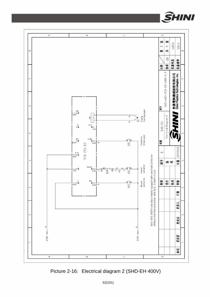
Picture 2-16:Electrical diagram 2 (SHD-EH 400V)

53(101)
2.3.11 Electrical Components Layout (SHD-EH 400V)
Picture 2-17:Electrical components layout (SHD-EH 400V)
54(101)
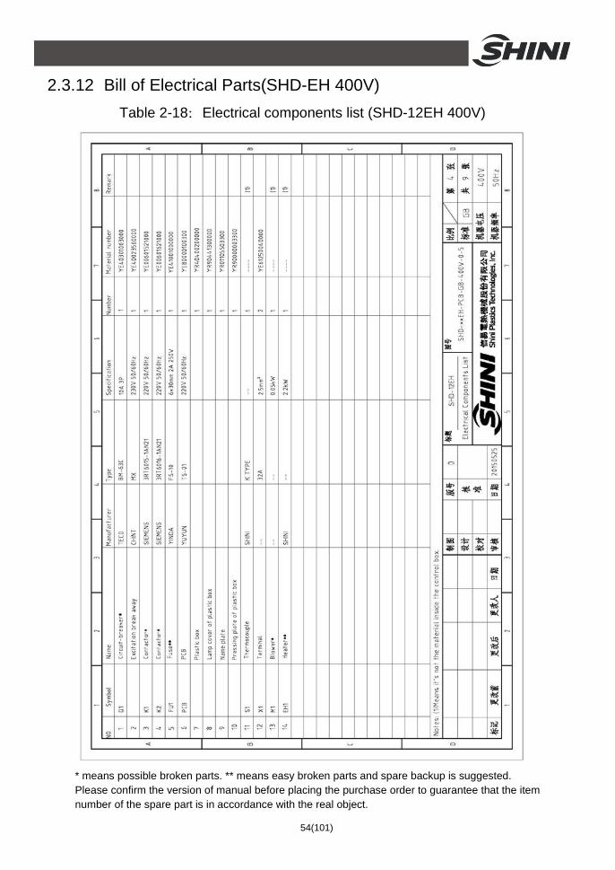
2.3.12 Bill of Electrical Parts(SHD-EH 400V) Table 2-18:Electrical components list (SHD-12EH 400V)
* means possible broken parts. ** means easy broken parts and spare backup is suggested. Please confirm the version of manual before placing the purchase order to guarantee that the item number of the spare part is in accordance with the real object.

55(101)
Table 2-19:Electrical components list (SHD-25EH 400V)
* means possible broken parts. ** means easy broken parts and spare backup is suggested. Please confirm the version of manual before placing the purchase order to guarantee that the item number of the spare part is in accordance with the real object.
56(101)
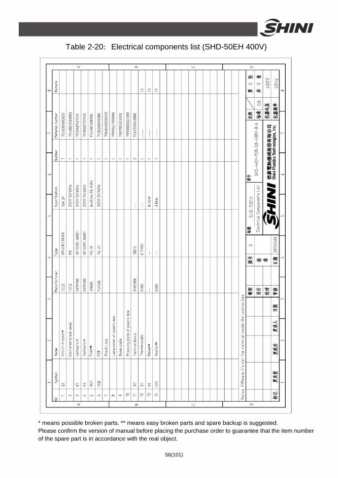
Table 2-20:Electrical components list (SHD-50EH 400V)
* means possible broken parts. ** means easy broken parts and spare backup is suggested. Please confirm the version of manual before placing the purchase order to guarantee that the item number of the spare part is in accordance with the real object.

57(101)
Table 2-21:Electrical components list (SHD-75EH 400V)
* means possible broken parts. ** means easy broken parts and spare backup is suggested. Please confirm the version of manual before placing the purchase order to guarantee that the item number of the spare part is in accordance with the real object.

58(101)
Table 2-22:Electrical components list (SHD-100EH 400V)
* means possible broken parts. ** means easy broken parts and spare backup is suggested. Please confirm the version of manual before placing the purchase order to guarantee that the item number of the spare part is in accordance with the real object.

59(101)
Table 2-23:Electrical components list (SHD-300EH 400V)
* means possible broken parts. ** means easy broken parts and spare backup is suggested. Please confirm the version of manual before placing the purchase order to guarantee that the item number of the spare part is in accordance with the real object.

60(101)
2.3.13 Power, Diameter, Current (SHD-12~300 230V)
Symbol Model
SHD-12 6.1 2.5 10 - - 1.0 0.05 0.3 1.5 2.2 5.8 SHD-25 8.1 2.5 15 - - 1.0 0.12 0.42 1.5 3.0 7.6
SHD-50 10.7 2.5 15 - - 1.0 0.12 0.42 2.5 3.9 10.2
SHD-75 11.5 2.5 15 - - 1.0 0.12 0.42 2.5 4.2 11
SHD-100 16.3 2.5 20 - - 1.0 0.12 0.55 2.5 6.0 15.8
SHD-150 16.3 2.5 20 - - 1.0 0.12 0.55 2.5 6.0 15.8
SHD-200 32.1 6.0 40 - - 1.0 0.18 0.8 6.0 12 31.5
SHD-300 40.1 10.0 50 - - 1.0 0.18 0.8 10.0 15 39.5
Total current Power cable diameter
Rated current of circuit breakers Drying blower loader
Settings for drying blower loader Drying blower diameter
Drying blower power Drying blower current
Wire diameter of heater Heater power
Heater current

61(101)
2.3.14 Electrical Diagram (SHD-12~300 230V)
Picture 2-18:Electrical diagram 1 (12~300 230V)

62(101)
Picture 2-19:Electrical diagram 2 (SHD-12~300 230V)

63(101)
Picture 2-20:Electrical diagram 3 (SHD-12T~300T 230V)

64(101)
2.3.15 Electrical Components Layout (SHD-12~300 230V)
Picture 2-21:Electrical components layout 1(SHD-12~300 230V)
65(101)
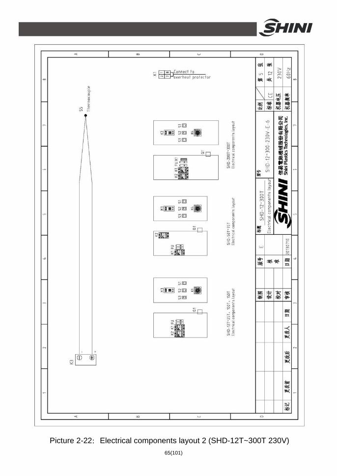
Picture 2-22:Electrical components layout 2 (SHD-12T~300T 230V)

66(101)
2.3.16 Electrical Components List (SHD-12~300 230V) Table 2-24:Electrical components list (SHD-12 230V)
* means possible broken parts. ** means easy broken parts and spare backup is suggested. Please confirm the version of manual before placing the purchase order to guarantee that the item number of the spare part is in accordance with the real object.

67(101)
Table 2-25:Electrical components list (SHD-25 230V)
* means possible broken parts. ** means easy broken parts and spare backup is suggested. Please confirm the version of manual before placing the purchase order to guarantee that the item number of the spare part is in accordance with the real object.

68(101)
Table 2-26:Electrical components list (SHD-50 230V)
* means possible broken parts. ** means easy broken parts and spare backup is suggested. Please confirm the version of manual before placing the purchase order to guarantee that the item number of the spare part is in accordance with the real object.

69(101)
Table 2-27:Electrical components list (SHD-75 230V)
* means possible broken parts. ** means easy broken parts and spare backup is suggested. Please confirm the version of manual before placing the purchase order to guarantee that the item number of the spare part is in accordance with the real object.

70(101)
Table 2-28:Electrical components list (SHD-100/150 230V)
* means possible broken parts. ** means easy broken parts and spare backup is suggested. Please confirm the version of manual before placing the purchase order to guarantee that the item number of the spare part is in accordance with the real object.

71(101)
Table 2-29:Electrical components list (SHD-200 230V)
* means possible broken parts. ** means easy broken parts and spare backup is suggested. Please confirm the version of manual before placing the purchase order to guarantee that the item number of the spare part is in accordance with the real object.

72(101)
Table 2-30:Electrical components list (SHD-300 230V)
* means possible broken parts. ** means easy broken parts and spare backup is suggested. Please confirm the version of manual before placing the purchase order to guarantee that the item number of the spare part is in accordance with the real object.

73(101)
2.3.17 Power, Diameter, Current (SHD-400~1000 230V)
Symbol Model
SHD-400 47.6 10.0 63 - 1.5 0.18 0.6 10.0 18 47 SHD-500 50.6 10.0 63 - 1.5 0.18 0.6 16.0 19.5 50
SHD-600 55.5 16.0 80 2.5 1.5 0.55 2.5 6.0x2 21 53
SHD-800 64.5 16.0 80 5.0 1.5 1.1 4.5 6.0x2 24 61
SHD-1000 86.5 25.0 100 5.0 1.5 1.1 4.5 10.0x2 32 82
Total current Power cable diameter
Rated current of circuit breakers Settings for drying blower loader
Blower cable diameter Drying blower power
Drying blower current Wire diameter of heater
Heater power Heater current

74(101)
2.3.18 Electrical Diagram (SHD-400~1000 230V)
Picture 2-23:Electrical diagram 1 (SHD-400~1000 230V)

75(101)
Picture 2-24:Electrical diagram 2 (SHD-400~1000 230V)
76(101)
2.3.19 Electrical Components Layout (SHD-400~1000 230V)
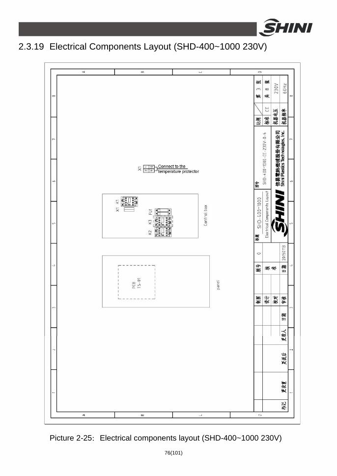
Picture 2-25:Electrical components layout (SHD-400~1000 230V)

77(101)
2.3.20 Electrical Components List (SHD-400~1000 230V) Table 2-31:Electrical components list (SHD-400 230V)
* means possible broken parts. ** means easy broken parts and spare backup is suggested. Please confirm the version of manual before placing the purchase order to guarantee that the item number of the spare part is in accordance with the real object.

78(101)
Table 2-32:Electrical components list (SHD-500 230V)
* means possible broken parts. ** means easy broken parts and spare backup is suggested. Please confirm the version of manual before placing the purchase order to guarantee that the item number of the spare part is in accordance with the real object.
79(101)
Table 2-33:Electrical components list (SHD-600 230V)
* means possible broken parts. ** means easy broken parts and spare backup is suggested. Please confirm the version of manual before placing the purchase order to guarantee that the item number of the spare part is in accordance with the real object.

80(101)
Table 2-34:Electrical components list (SHD-800 230V)
* means possible broken parts. ** means easy broken parts and spare backup is suggested. Please confirm the version of manual before placing the purchase order to guarantee that the item number of the spare part is in accordance with the real object.

81(101)
Table 2-35:Electrical components list (SHD-1000 230V)
* means possible broken parts. ** means easy broken parts and spare backup is suggested. Please confirm the version of manual before placing the purchase order to guarantee that the item number of the spare part is in accordance with the real object.

82(101)
2.3.21 Electrical Diagram(SHD-12EH 230V)
Picture 2-26:Electrical diagram 1 (SHD-12EH 230V)

83(101)
Picture 2-27:Electrical diagram 2 (SHD-12EH 230V)

84(101)
2.3.22 Electrical Components Layout (SHD-12EH 230V)
Picture 2-28:Electrical components layout (SHD-12EH 230V)

85(101)
2.3.23 Electrical Components List (SHD-12EH 230V) Table 2-36:Electrical components list (SHD-12EH 230V)
* means possible broken parts. ** means easy broken parts and spare backup is suggested. Please confirm the version of manual before placing the purchase order to guarantee that the item number of the spare part is in accordance with the real object.

86(101)
3. Installation and Debugging Notes for Installation and Positioning: 1) Machine just can be mounted in vertical position. Make sure there’s no pipe,
fixed structure or other objects above the installing location and around the machine which may block machine’s installation, hit objects or injure human person.
2) In order to maintain convenient operation, it’s suggested to keep 1m space around the machine. Please keep at least 2m distance between the device and the inflammable goods.
3) This series of models only could be applied in working environment with good ventilation.
3.1 Direct Installation
Picture 3-1:Direct installation
Direct installation type is to mount the hopper dryer directly on the molding machine via a standard base. SHD-12~300 is suitable for this mounting method as well as floor stand installation type; SHD-400 and models above should adopt floor stand installation type. When using the method to mount the dryer, the equipped standard base must

87(101)
according to material inlet diameter of the molding machine mounting drill holes. Then use the screw to fasten the base and the molding machine inlet.
3.2 Floor Stand Installation
Picture 3-2:Floor stand installation Floor stand installation type is to mount dryer on a floor stand, then via a photo-sensor hopper receiver to convey the material to the feed port of a molding machine. SHD-400 and above models should adopt floor stand installation type.
Machine should be placed on water-level floor to keep balance. If it is to be mounted on a high surface(e.g. on a scaffold or a interlayer), should ensure its structure and sizes can bear the weight and size of the machine.
3.3 Connecting the Power Source Open the control box and connect the power source in accordance with wiring diagram. Notice should be taken concerning if the power voltage is in compliance with the required specifications, also if the switch and load are proper and safe.
Notes: Before connecting, the main switch and heat switch should be off.
3.4 The Hopper Dryer Test After ensuring all the circuits have been connected firmly, turn on the blower switch to” ON” status and turn on the heater switch on control box to “ON” status. Then light indicator of the switch would turn on, observe whether the rotating derection of the blower is same as the arrow indicated direction. If it is not, randomly exchange two of the three power firing lines and connect them firmly.

88(101)
Picture 3-3:Blower
3.5 Installation of the Options 3.5.1 Installation of Air-Exhaust Cyclone Dust Collector /Air-Exhaust
Filter If the materials contain dust or to avoid the dust-contain air exhausted by dryer polluting the workshop’s environment. Option with air-exhaust cyclone dust collector HCF or air-exhaust filter ADC can filter the exhausted air from the dryer. HCF can reach filter efficiency of 80% and ADC can reach filter efficiency of 99%. Both HCF/ADC are installed on air-exhaust elbow of the dryer. Point it to the installed holes then tighten up the screws, use rubber ring to seal the combined place.
Picture 3-4: Left : Air-exhaust elbow of dryer
Middle : Air-exhaust cyclone dust collector Right: Air-exhaust filter

89(101)
3.5.2 Suction Box Installation
Picture 3-5:European suction box
When SHD is mounted on the floor stand suction box should be equipped. To convey the dried plastic material conveniently. The installation of suction box is simple. Install them at bottom of the hopper, point to the holes and tighten up the screws.
Picture 3-6:Shut-off suction box
3.5.3 Blower Inlet Filter Installation When dryers in the dust-contain environment or hot air requires high cleanliness, it can option with AIF blower inlet filter.

90(101)
Picture 3-7:Right:AIF blower inlet filter
Installing AIF at blower inlet port when installing it, firstly loosen screws of the blower inlet screen , take down the screen; then install the AIF at blower inlet port, point to the holes and tighten up the screws.
3.5.4 Hot Air Recycler Installation Based on AIF blower inlet filter, using a hear-resistance pipe to connect the hopper exhausting air to AIF. Thus to form a hot air recycler. By recycling the hot air can at most save energy consumption by 40%.
Picture 3-8:Hot air recycler
91(101)
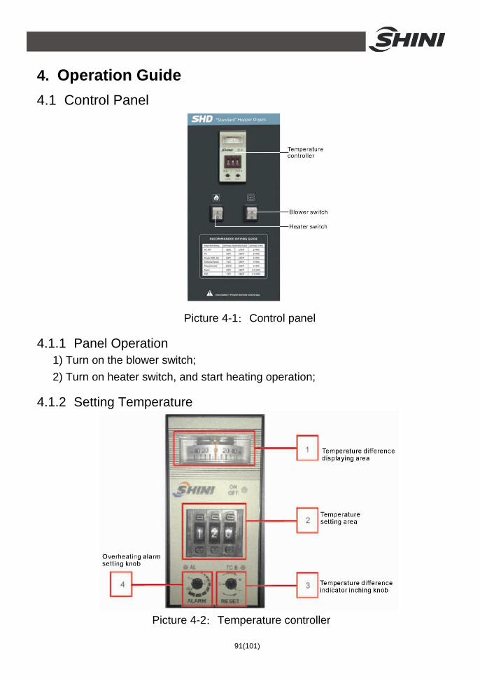
4. Operation Guide 4.1 Control Panel
Picture 4-1:Control panel
4.1.1 Panel Operation 1) Turn on the blower switch; 2) Turn on heater switch, and start heating operation;
4.1.2 Setting Temperature
Picture 4-2:Temperature controller

92(101)
As figures on above picture 4-2: 1. Temperature difference display area. It is used to display difference value
between actual temp. and set temp. For example, if actual temperature is lower than set temp., the pointer turns left (negative direction), otherwise, it turns right( positive direction).
2. Temperature set area. Set value range: 0~199℃,when heating process lasts for some time, “on/off” indicator light on temperature controller will display yellow and green light alternatively. It means the set temperature is reached. At the same time, observe if the value on temperature controller is consistent with the thermometer or not. The acceptable deviation is ±2℃.
3. Inching knob of temperature difference pointer. When the working temperature runs stably (about 1 hr after the start), the pointer should be at “0” (the difference value between actual temperature and set value), otherwise adjust the pointer to “0” is available by rotating the inching knob.
4. Overheat indicator setting knob. When actual temperature is no less than set value alarming value, temperature controller has alarming output, the factory set value is 15℃.
Temperature controller panel indicator light description as below: ON/OFF:ON status green light on, OFF status red light on; AL: light on means over temperature alarm output; TC B: light on means temperature sensor line breaks
Notes: Drying temperature setting of plastic material must be in accordance with related drying temperature. If temperature gets too high, it would make material blocked and potentially cause serious accident. Thus the temperature setting must collocate with actual experience.
Moreover, the dryer equipped with overheat protective device. SHD-25~150 adopts lead sheet as the protector when overheat breaking happened. When flowing through heater is bigger or heating pipe temperature higher than 328℃, the lead sheet will break itself and stop heating (as picture 4-3). SHD-200 and models above, adopts overheat protectior It is mounted on fixing pole at the back of control box. When detecting the temperature of fixing pole over 130℃, the protector will cut off the power supply (as picture 4-4).

93(101)
Picture 4-3:Lead sheet fuse
Picture 4-4:Overheating protector
4.2 Control Panel with Dryer
Picture 4-5:Control panel (with timer)

94(101)
4.2.1 Panel Operation 1) Turn on blower switch; 2) Turn on heater switch, start heating operation; 3) Turn on the timer switch, set time to dry the material.
4.2.2 Timer Setting
Picture 4-6:Timer
1. Under the condition that all the switches turned on, turn on the timer switch . 2. Take down the transparent cover of the timer, push the little gray switch at left
conner on top of the timer to “Auto” status. Set the pressure electrical frequency at top right conner of timer to current customer’s frequency.
3. Current time setting. As the picture 4-6, rotate the “TIME SET DIAL” knob at middle of the timer clockwise to set current time. In the middle is 12-hour white circle dial, the outside is 24-hour gray circle dial. Please pay special attention to distinguish them. As above picture, it set time is half past four in the morning, just the 4:30 am.
4. Requirement drying hour setting. Press timer’s outer teech down to the inner circle. The pressing range is the drying hour from beginning to the ending. As above picture, when it reaches 8 o’clock, the machine starts work; till 4 o’clock in the afternoon, the machine stops. Everyday repeat the circulation.

95(101)
4.3 Control Panel(SHD-400~1000)
Picture 4-7:Control Panel(SHD-400~1000)
4.3.1 Panel Operation
1) Turn on main power switch of control box. 2) Press “RUN/STOP” key, it starts drying process, indicator turns green; 3) Press “RUN/STOP” key again, it stops drying process, indicator turns yellow
4.3.2 Temperature Setting
1) The setup number will flicker after pressing "Meun" key, add or decrease temperature by pressing“Up”or “Down”key.
2) Press " Setup" key again to confirm the input value.
4.3.3 Temperature Lock
1) Press “menu” key for 2 seconds, it displays “TIME”. 2) Press “page up” repeatly, till it display “LOCK”; 3) Press “Setup” key, the set value flickers, press “Up”or “Down” key to select “YES”(lock temperature setting) and “NO” (don’t lock).
4) Press “Setup” key to confirm the input value. 5) Press “Menu” key to return operation menu.
Notes: When “LOCK” is set as “YES, temperature setting value will be locked which not accessible to change.

96(101)
4.3.4 PID Setting
1) Press both “Menu” and “Down” keys for 3 seconds, it shows “P” (proportion) setting;
2) Press “Setup” key, the set value flickers, then press “Up”or “Down” key to add or decrease the value.
3) Press “Setup” key to confirm the input value.
4) Press “page up” key again and again, it displays “I” (integral time ) and “D” (differential time) setting accordingly.
5) Repeat above step2 and step 3, input and confirm related parameters.
6) Press “Menu” key, it returns operation menu.
Notes: The PID parameter will directly influence the effect of temperature control, please be careful to set the value.

97(101)
Parameters Codes Factory Default
Proportion P 5 Integral time I 200 Differential time D 30 Over-temp alarm OTP 15℃ Control cycle HCLE 15 Blower delay FDLY 180 Temp. unit UNIT ℃
4.3.5 Intermittent Operation Setting
1) Hold “Menu” for about 2 secs. to set current time and week. Press “Up” or “Down” key to set start/stop function of AUTO timer, the time for RONE intermittent operation, the OFF time of ROFF intermittent operation, the ON time of RON intermittent operation.
4.3.6 One-week Timing Setting 1) After current time is set, hold “menu” for about 5 secs, press “Up” or “Down”
key to set OFF1 (Mon. off time), OFF2(Tues. off time), OFF3 (Wed. off time), OFF4(Thur. off time), OFF 5(Fri. off time), OFF6(Sat. off time), OFF7(Sun.off time).
2) Hold “Menu” for about 7S, press “Up” or “Down” key to set ON1(Mon. start time), ON2(Tues. start time), ON3(Wed. start time), NO4(Thur. start time), ON5(Fri. start time), ON6(Sat. start time), ON7(Sun. start time).
4.3.7 Communication Setting (optional functions)
1) Press both “Menu” and “Up” for 3 seconds, it displays “PRO”(communication protocol) setting.
(Notes: communication protocol is fixed to Modbus RTU protocol—“RTU”.)

98(101)
2) Press “page up” key to enter “ID” (communication address) setting; (Notes: The communication address of every controller in the same system
must be the only one, no repeat use. In principle: communication address of hopper 1 is 1, communication address of hopper 1 is 2, and so on.)
3) Press “Setup” key, the set value flickers, then press “Up”or “Down” key to add or decrease the value.
4) Press “Setup”key to confirm the input value; 5) Press “page up” key again and again, it displays “Baud” and “PAR” settings,
(as below )
6) Repeat step 3 and step 4, then confirm the related input parameters. 7) Press “Menu” key to return operation menu.
Communication Parameters
Communication Codes
Factory Default
Communication Protocol PRO RTU Communication Address Id 1(current address)
Baud Rate Baud 19.2K
PAR PAR none
Data Length Data 8
Stop Bit Stop 1

99(101)
P Heating ratio Rang:1-100℃ Default:40℃
I Integral Rang:0-999S Default:120S
D Differential Rang:0-999S Default:20S
OTP Overheat temp. protection (SV+F-05) Rang:2-50℃ Default:15℃
100C
HCLE Heating cycle Rang:15-60S Default:15S
OFF1 Mon. off time 00:00=OFF
OFF2 Tues. off time 00:00=OFF
OFF3 Wed. off time 00:00=OFF
OFF4 Thur. off time 00:00=OFF
OFF5 Fri. off time 00:00=OFF
OFF6 Sat. off time 00:00=OFF
OFF7 Sun. off time 00:00=OFF
ON 1 Mon. start time 00:00=OFF
ON 2 Tues. start time 00:00=OFF
ON 3 Wed. start time 00:00=OFF
ON 4 Thur. start time 00:00=OFF
ON 5 Fri. start time 00:00=OFF
ON 6 Sat. start time 00:00=OFF
ON 7 Sun. start time 00:00=OFF
TIME Current Time(hr,min)
RON Intermittent run ON time Rang :30-600 (Min) Default:30
ROFF Intermittent run OFF time Rang:0 – 600(Min) Default:0
RONE Intermittent intial run time Range:30-600(Min) Default:90
UNIT Temperture unit Rang:℃-℉ Default:℃
AUTO Timing start/stop Rang;AUTO-OFF Default:OFF
WEEK Current Time (hr,min)
FDLY Blower delay Rang:30-360S Default:180S
LOCK SV setting lock Rang: YES– NO Default:NO
PRO Communiation protocol Rang: MODBUS-RTU
ID Communiation ID Rang:1-99 Default:1
BAUD Rang:4.8K 9.6K 19.2K Default:9.6K
PAR Parity bit Rang:NONE,Odd,Even Default:Odd
Data Data length Rang:8bit Default: 8bit
Stop Stop bit Rang: 1bit,2bit Default: 1bit
M+△+3S
SV Rang:0-200℃ Default:90℃ 100C
M+2S M+5S M+▽+3S M+7S
△/▽ △/▽ △/▽ △/▽ △/▽
M Exit
4.3.8 Operation Flow
M stands for:Menu key
△/▽stands for:Up/Down key

100(101)
4.3.9 Wrong Codes Remark
Wrong Codes Remark
bR Thermocouple break alarm oH Over-temp alarm oL Overload alarm EGO EGO Over-temp heater cable cut off

101(101)
5. Maintenance and Repair 5.1 Blower
1) Clean the blower regularly (especially the air inlet path). 2) Eliminate the fan's dirt regularly to avoid the damage to the blower.
Attention! No need for regular inspection because all the electrical parts in the control unit are fixed tightly!
6. Troubleshooting
Fault Possible Reasons Solution
Blower rotating on the contrary with arrow
Blower circuit connection reverse phase.
Exchange two of theel ectrical wires.
Blower not turning hot air pipe reeky
1. Motor fault. 2. Failures of solenoid switch.
1. Check and change. 2. Change or repair.
Blower not rotating and not heating
1. Overload jumped. 2. Transformer fault. 3. Fuse melted. 4. Power supply fault.
1. Check and change. 2. Check and change. 3. Check and change. 4. Check if lack of phase.
No temperature for blower running
1. Plumb slip of heater pipe melted. 2. Magnetic switch fault. 3. Heater pipe fault. 4. Power supply fault. 5. Thermocouple fault.
1. Check and change. 2. Check and change. 3. Check and change. 4. Check if lack of phase. 5. Change.
The blower can run but temperature is too low
1. Plumb slip of heater pipe fault. 2. EGO jumped or breaking. 3. Magnetic switch is lack of phase. 4. Temperature controller is
damaged or its error is too much.
1. Check and change. 2. Check or re-set. 3. Check and change. 4. Change the temperature
controller.
The blower can run but temperature is too high
1. Hot-air pipe is jam. 2. Temperature controller is fault or
its error is too much. 3. Electromagnetic switch contacts
stuck up.
1. Cleaning. 2. Change the temp. Controller
or adjust inching switch. 3. Change.
Notes: Before inspecting or changing spare parts, ensure the main switch should be off.