1986 · activates a counter 1n the console which keeps track of the number ... controls both the dc...
TRANSCRIPT

OPERATING MANUAL FOR THE DIGITAL DATA-COLLECTION SYSTEM
FOR FLOW-CONTROL STRUCTURES
By James I. Rorabaugh and William L. Rapp
U.S. GEOLOGICAL SURVEY
Open-File Report 85-691
National Space Technology Laboratories, Mississippi
1986

UNITED STATES DEPARTMENT OF THE INTERIOR
DONALD PAUL MODEL, Secretary
GEOLOGICAL SURVEY
Dallas L. Peck, Director
For additional information Copies of this report can bewrite to: purchased from:
Chief, Hydrologic Instrumentation Facility Open-File Services SectionU.S. Geological Survey, WRD Western Distribution BranchBuilding 2101 Box 25425, Federal CenterNSTL, MS 39529 Denver, CO 80225
(Telephone: (303) 236-7476)

ERRATA
This operating manual, Open-file report 85-961, is meant to assist USGS field personnel in trouble-shooting and servicing the Digital Data- Collection System components and not to delve directly with the inner workings of the basic electronics. Field repair and calibration of the electronic boards and circuitry is not done. Should more details be required concerning the schematics on pages 33 through 39, contact the authors at the Hydrologic Instrumentation Facility.

CONTENTS
Page 1.0 Introduction .................................................. 1
2.0 Operating instructions ........................................ 1
2.1 On/off switch .......................................... 12.2 Advance and reset switches ............................. 12.3 Setting the clock ...................................... 42.4 Loading paper tape ..................................... 42.5 Setting the record interval ............................ 42.6 Punch on/off switch .................................... 62.7 Manual-punch switch .................................... 6
3.0 System operation .............................................. 6
3.1 Data and enable lines .................................. 63.2 Punch cycle ............................................ 83.3 Channel control ........................................ 93.4 Dummy channel .......................................... 93.5 Clock card ............................................. 93.6 Lock counter ........................................... 103.7 Power supplies ......................................... 103.8 Telemetry .............................................. 10
4.0 Performance checks and repair ................................. 13
4.1 Troubleshooting procedure .............................. 134.2 Console testing using the test box ..................... 164.3 Testing the power supply ............................... 174.4 Changing console circuit cards ......................... 184.5 Checking the card-rack wiring .......................... 194.6 Testing the recorder solenoids ......................... 194.7 Testing digitizer diodes ............................... 204.8 Testing cables external to the console ................. 22
4.8.1 Using the test box at the console ............... 224.8.2 Using the test box at the digitizer ............. 234.8.3 Testing a cable with an ohmmeter
for shorts ...................................... 264.8.4 Testing a cable with an ohmmeter
for open wires .................................. 27
4.9 Testing the lock counter ............................... 28
4.9.1 Using the lock-counter test cable ............... 284.9.2 Testing the external lock cable
and switch ...................................... 29
4.10 The recorder-brake circuit ............................. 30
4.10.1 Testing the recorder brake ...................... 30
iii

APPENDIX
Schematic diagrams for cards 1, 5, 9, 13 » 15,17, and 21 ............................................... 31
FIGURES
Figure 1. Diagram of the digital data-collection system as usedon a typical f1ow control structure ...................... 2
2. Photograph of front of console showing controls .......... 33. Photograph showing clock-card record-Interval setting .... 54. Diagram of electrical console ............................ 75. Diagram of lock counter .................................. 116. Diagram of power supplies ................................ 127. Diagram showing electrical hookup for testing diodes ..... 218. Diagram showing generalized electrical hookup
at typical dam instal1ation .............................. 24
TABLES
Table 1. P1n Identification for telemetry jack J8 .................. 132. Trouble-shooting table for the digital data-collection
system .................................................... 14
1v

OPERATING MANUAL FOR THE DIGITAL DATA-COLLECTION SYSTEM FOR FLOW-CONTROL STRUCTURES
1.0 INTRODUCTION
This manual was written to help the user operate and maintain the digital data-collection system for flow-control structures. The system 1s used to measure dally discharge through river-control dams. These dams commonly have talnter gates which are raised and lowered to keep the upper pool level relatively constant as the river flow changes. In order to measure the flow through such a structure* the positions of the talnter gates and the headwater and tallwater elevations must be known. From these data, the flow through the structure can be calculated. A typical digital data-collection system 1s shown 1n figure 1. Digitizing devices are mounted on the hoisting mechanism of each gate, as well as at the headwater and tallwater gages. Data from these digitizers are then routed by electrical cables to a central console where they are displayed and recorded on paper tape. If the dam has locks, a pressure-sensitive switch located 1n the lock activates a counter 1n the console which keeps track of the number of times the lock 1s drained and filled.
2.0 OPERATING INSTRUCTIONS
2.1 On/Off Switch
The on/off switch (fig. 2) controls both the dc and ac power to the console. In the on position, dc power from the batteries supplies the console electronics while ac power 1s used to float charge the batteries. The pilot light above the switch will be on 1f the console 1s connected to 110-volt ac power. Note that unplugging the console's ac power cord does not turn off the console because of the battery standby. The on/off switch Must be used to turn off the console.
2.2 Advance and Reset Switches
These two switches are located just below the digital display on the console (fig. 2). A duplicate set 1s found on the lockmastep's remote display. These switches let the user view the data on a desired channel. The display above these switches 1s divided Into two parts: the left two digits give the channel number, and the right four digits give the data 1n that channel. The channel Indicator will advance to the next channel when the advance switch 1s pressed. The reset switch 1s used to return to channel 0. When the punch cycle or telemetry 1s 1n progress, these two switches are Inoperative, and the Interrogate (telemetry) or the punch-cycle Indicator light will be on.

ISJ
49'
SP
D
=
SH
AF
T P
OS
ITIO
N
DIG
ITIZ
ER
S
OF
=
S
HA
FT
OU
TP
UT
FO
LLO
WE
R
ST
AC
OM
=
S
TA
BIL
IZE
D &
TE
MP
ER
AT
UR
E
CO
MP
EN
SA
TE
D M
AN
OM
ET
ER
Fig
ure
1. T
he d
igita
l d
ata
-co
llectio
n
syst
em
as
used
on
a
typ
ica
l flow
-contr
ol
str
uctu
re.

© 0
Figure 2.
Fron
t of
co
nsol
e sh
owin
g controls,

2.3 Setting the Clock
Before setting the clock* the console should be turned on and the channel display should be on 00. The data digits now represent the time In hours and minutes on a 24-hour clock (fig. 2). To set the clock* proceed as follows:
1. Press the clear switch.
2. Press the fast-advance switch and hold In until the hour digits read the proper value. Remember* this is a 24-hour clock.
3. Press the slow-advance switch until the desired minutes are reached. If the desired time is overshot, return to step 1.
4. The hold switch is used to set the clock to the exact second. When pressed, time is held and the seconds are set and held at zero until the switch Is released. Exactly one minute after this switch Is released the minute digit will advance.
2.4 Loading Paper Tape
Refer to the instruction manual for the Leupold and Stevens model 7001 paper-tape punch. The recorder is in the top console drawer. CAUTION; If the paper tape 1s changed while the console Is on, keep hands and fingers away from the gears. The console could suddenly enter a punch cycle.
After loading the paper, It is usually desirable to punch some feed holes In the tape. To do this, press the manual-punch switch located Inside the top drawer of new consoles and on the front panel of older consoles (fig. 2). This will Initiate a complete punch cycle and enter the param eters punched at your Installation. If more holes are desired, press the button again. It Is recommended that the paper-advance button on the Stevens recorder not be used as It may cause the recorder to stop in the wrong position, producing an error In the first data recorded. If the manual-punch switch is depressed for more than 60 seconds, a safety circuit will stop the recorder. The only way recording can be resumed 1s to turn the console off for about 10 seconds and then turn 1t back on. The purpose of the safety circuit is to prevent the recorder from running continuously In the event of a circuit-card failure.
2.5 Setting the Record Interval
The record Interval is set by a jumper plug on the clock card (card 1). Schematic diagrams of cards 1, 5, 9, 13, 15, 17, and 21 are included in the appendix. To change the record Interval:
1. Turn off the console power. CAUTIONi Cards may be damaged If removed or replaced while power is on.
2. Remove card 1 from the card rack in the rear of the console.
3. Find the proper card (fig. 3) and identify the position of the jumper for the desired record Interval.

4. Move the jumper to this position.
5. Return the card to the rack making sure the red card handle 1s at the top of the rack. CAUTION; Inserting the card with the white handle up will destroy the card.
SOCKET 6 SOCKET 13
1
2
3
4
5
6
7
8
1 HR
2 HR (ODD)
16
15
14
13
12
11
10
9
1
2
3
4
5
6
7
8
*EARLY VERSIONS LACK 2 HOUR ODD MODE. THESE WILL NOT HAVE WIRES ATTACHED ON PINS 6 AND 11 ON THE WIRE WRAP SIDE OF SOCKET 6.
PUNCHES ON ODD HOUR
16
15
14
13
12
11
10
9
Figure 3. Clock-card record-Interval setting.

2.6 Punch On/Off Switch
The punch-cycle on/off switch Is located In the back of the console on card 21. If the switch Is In the down (off) position, the recorder will not punch. If It is in the up (on) position, the recorder will punch normally. This switch can be changed while the console is on without removing card 21. This switch does not affect any other console operation.
2.7 Manual-Punch Switch
In the newest console models, the manual-punch switch is located inside the top drawer to prevent inadvertent manual-punch cycles. Its purpose is to allow the operator to check the punch operation while servicing the con sole. It should only be used when the paper tape record is being removed and restarted.
If the manual punch is activated during the middle of a data record, the block of data punched on the recorder tape will be tagged with the cor rect time of day. However, that block of data now occupies the space on the tape that was intended for the next automatically-sequenced punch cycle. Thus, all subsequent blocks of data punched on the tape will be physically displaced by this amount of space, and the time scale (as read from the tape) will be similarly displaced.
3.0 SYSTEM OPERATION
3.1 Data and Enable Lines
Refer to the block diagram in figure 4. The digitizers are linked to the console through two basic sets of electrical lines. One set contains the 16 data lines which are wired in parallel to all of the digitizers. These lines carry the data in four-digit, binary-coded-decimal (BCD) format. The 16 lines, from the most significant bit to the least significant bit, represent the data values 80, 40, 20, 10, 8, 4, 2, 1, 0.8, 0.4, 0.2, 0.1, 0.08, 0.04, 0.02, and 0.01. The second set of lines in the system is the collection of enable lines, each running separately to a digitizer. Each enable line terminates in the console at a separate relay contact on circuit-card 15. The console reads the data from a digitizer as shown below:
1. The desired channel number is sent from the programmer (card 21) to the multiplex (card 13) which has a relay-drive transistor for each digitizer.
2. Card 13 decodes the channel number and turns on the proper relay- drive transistor.
3. The relay-drive transistor in turn activates the relay on card 15 for the proper digitizer, which grounds the enable-line of the selected digitizer.
4. The grounded enable line sets up an electrical path via each data line for which there is a closed switch in the selected digitizer.

DIGITIZERS LOCATED AT HEADWATER, TAILWATER AND GATES.
(0c
CD £t
I i. O fa
O O3w> O
CD cr
O o7T
(Q
CHANNEL tNABLt LINES ONE TO tA
PARALLEL TO ALL DIGITIZERS
DECODER LOGIC BCD CHANNEL INPUT TURNS ON DESIRED TRANSISTOR
LOGIC TO SELECT CHANNEL NUMBER FROM PROGRAMER OR TELEMETRY
TIME ENABLE FROM CARD 13

5. Current from the V2 power supply in the console can now transverse activated data lines, each one of which terminates at its own opti cal coupler on card 17 in the console.
6. At card 17, the current signal passes through a light-emitting diode (LED) which illuminates a phototransistor.
7. Each transistor so activated delivers a signal over the appropriate buffered data line to cards 5 and 9.
8. From card 5, the data are sent on command from the programmer(card 21) to the punch solenoids causing holes to be punched in the 16-channel paper tape for each digitizer switch that has been found closed.
9. From card 9, the data are sent to the displays on the front panel of the console as well as to the lockmaster remote display. Also from card 9, data are sent to telemetry plug, J8, on the rear of the console.
Note in figure 4 that a diode is placed in each data line in each digitizer. The diode acts as a one-way flow valve and keeps the current flow in an energized data line from getting into an unenergized digitizer's enable line. Thus, the only time current can flow through a digitizer's switch from a data line is when that digitizer's enable line is grounded, providing a return path for the current. Any return path by way of another data line has been cut by the reverse blocking action of the diodes.
3.2 Punch Cycle
The programmmer (card 21) is the "brain" of the console. It controls the punch operation, manual advance and clear switches, and the telemetry access. The schematic diagram is presented in the appendix to help clarify its operation.
A punch cycle is initiated by a pulse from the clock which turns on a punch-cycle flip-flop. If the telemetry (TM) is not on, this punch-cycle signal resets the channel counter to zero and prevents further operation of the manual advance and clear switches. If the punch is ready to punch, that is, the motor is Off (recorder pin 2 is low), punch-coil 1 of the latching relay is activated, which pulls the relay to the punch position. The punch motor then runs until the switch in the analog digital recorder (ADR) goes to the reset position, which causes signal M (ADR pin 4) to drop low in voltage while ADR pin 2 is still high. This sequence of events causes a pulse on coil 2 of the relay, which pulls the relay to the reset position. At the same time, the channel counter is advanced by one.
If the punch cycle is still on after the ADR resets, the punch relay coil 1 will once again be activated causing the process to repeat. Thus, the punch and channel counter will continue cycling until the punch-cycle signal is turned off by a stop signal from a selected channel enable line on card 13. This stop signal also resets the channel counter to zero. The desired stop channel is determined by a jumper wire on the back of card 13. If the programmer fails to receive a stop signal, a one-minute punch-limit

circuit will stop the recorder. However* the programmer will then be locked up and neither the manual channel switches, the TM, nor the next record cycle can function. (See section 2.4.)
3.3 Channel Control
The channel number is generated by two binary-coded-decimal counters on card 21. The channel counters are incremented each time the advance switch on the console or the lockmaster f s remote display is pressed. The clear switches reset the channel counter to 00. When the punch cycle starts, the advance and clear switches are locked out and the channel counter is cleared. As each parameter is recorded, the channel number is incremented. Upon completion of the record cycle, the channel counter is reset to 00 and control is returned to the advance and clear switches. The channel number is sent from card 21 to the multiplex (card 13), where it passes through a data selector. The data selector accepts the program-card channel number if the telemetry is turned off. If the telemetry should be on, however, a channel number from telemetry plug J8 is accepted instead. The accepted channel number then goes to the channel displays by way of 12-volt to 5-volt buffer chips. It also goes to decoding circuitry on card 13 which turns on the relay driver for that channel. These activate the enable-line relay for that channel.
3.4 Dummy Channel
The dummy channel data are set by diodes located on modules plugged into sockets 7 and 8 on card 9. The dummy functions exactly as a digitizer with fixed switches. For one bit on a particular data line, a diode is soldered from that data line to the dummy enable line. For no value, the diode is omitted. Thus, the dummy data can be changed by adding or clipping diodes on card 9 (sockets 7 and 8). The channel number of the dummy is controlled by a wire-wrap wire on the rear of the card rack. (Contact the HIF if any change is necessary.) The purpose of the dummy channel is to separate data blocks on the paper tape with a known value and to make the number of recorded parameters fit the available types of paper tape.
3.5 Clock Card
Two different time-card types have been used in the console. These cards are interchangeable and provide the same basic functions. Both cir cuits employ a 32768 Hz crystal oscillator. This frequency is counted down to 2 Hz and then divided by 120 to give 1 pulse per minute. The 1-minute pulses are then fed to a binary-coded-decimal counter which counts from 00 to 59 minutes. When the counter reaches 59, the next count activates a reset circuit which sets the counter back to 00 and causes a BCD hours counter to be incremented. A similar circuit on the hours counter resets it on the next count after 23. An output-pulse circuit monitors the hour val ues and upon reaching the punch time sends a pulse to the programmer card to start the data-recording cycle. The outputs of the binary-coded-decimal minute and hour counters are sent to card 5, and if the channel number is zero, card 5 puts them onto the buffered data 1ines. From here, the time data goes to the displays or telemetry by way of card 9 or to the recorder by way of card 5.

3.6 Lock Counter
Two lock-counter Input jacks are on the rear of the console. The jack labeled J5 is for a large lock* and the jack labeled J6 1s for a small lock. The small lock circuit causes the lock counter to count once when the lock is emptied, while the large lock circuit counts once when the lock is filled and again when it is emptied. Figure 5 illustrates the counter circuitry. When a pressure switch in a lock is closed* current flows through a dropping resistor on card 9, to the switch in the lock, through the switch, and back to card 9, where it flows through an LED optical coupler. The optical cou pler output relays this signal to a pulse circuit, which sends a pulse to the solenoid drive circuit. For the large lock, the pulse is sent both upon switch opening and closing. For the small lock, the pulse is sent only upon switch closing. The pulse is amplified by the solenoid drive circuit and sent to the solenoid in the lock-counter digitizer in the top drawer. This causes the digitizer to advance one count.
3.7 Power Suppl ies
The console's three power supplies are: The VI that powers the logic on the circuit cards, the V2 that powers the digitizers, and the 5-volt supply that powers the displays on both the console and the lockmaster's remote display. The V2 power supply was added to the system to isolate the digitizer cables running to the console from the logic circuits. This iso lation is necessary because the long cables connected to the console often pick up transients that can destroy integrated circuit (1C) logic chips. Data pass between the V2 and VI systems by way of optical couplers and relays, affording several thousand volts of isolation between the two sys tems. The 5-volt supply is derived from the VI supply by a regulator in the bottom drawer of the console. The 5-volt output of this regulator is then routed to cards 9 and 13 and the displays. Figure 6 shows how the supplies are connected and the location of the fuses in the system. For more infor mation on the charger regulator used to charge the VI and V2 batteries, see the operating manual for the USGS regulator.
3.8 Telemetry
The telemetry channel is accessed through jack J8 on the rear of the console. The telemetry device must supply a telemetry request signal to pin 17 of J8, along with eight channel-number signals in binary-coded-decimal digits. The programmer (card 21) will wait for the completion of any record cycle in progress, then it will turn on the telemetry and send a telemetry on signal to J8, which lets the telemetry device know that it has access. At the same time, the data for the requested channel are made available at telemetry jack J8 by way of drivers on card 9. Once access is gained, the telemetry device can keep sending channel numbers to the console until all the required data are obtained. When the telemetry device is in control and a record cycle is started by the clock or manual-punch switch, the record cycle will be held until the telemetry finishes.
10

LARG
E!"
LOC
K
I
mt
^amJ
t <^ i M
M
>
J5 ? 3 J6
1 2 3
r
"^~
-^
.
CA
RD
5
R
V2
^^^^ «^* H
^1
i*
'^^'1
f '
1R
V2
^^
e
T y U
l f-y/M
*""^
"*"
"
-
^^~
LAR
GE
LO
CK
PU
LSE
C
IRC
UIT
E
MP
TIE
DP
ULS
EC
IRC
UIT
F
ILL
ED
PU
LSE
CIR
CU
IT
SM
AL
L L
OC
K
^^ - f
1
SO
LE
NO
IDD
RIV
E
1 _
i P»
PK
DIG
ITIZ
ER
IN T
OP
D
RA
WE
R
SM
AL
L
FIL
LE
D
=
OP
EN
LO
CK
I H
I E
MP
TY
=
C
LOS
ED
Fig
ure
s. Lock-c
ounte
r b
lock
d
iag
ram
.

ON/OFFFRONT PANEL
FUSE 21/2 A
110-VAC
LINE
TRANSIENT PROTECTOR
CENTERDRAWERCOMPONENTS
BOTTOM DRAWER COMPONENTS
12-V LEADACID BATTERY
5-8 AMP HOURS
12-V LEADACID BATTERY
5-8 AMP HOURS
V1 SUPPLY
TO CIRCUIT CARD LOGIC INTEGRATED CIRCUITS
V2 SUPPLY
TO DATA LINE BY WAY OF RELAYS AND OPTICAL COUPLERS (CARDS 15 AND 17)
TO DISPLAYDRIVERS CARDS 5 AND
Figure 6. Block diagram of power supplies.
12

If the telemetry takes more than about 30 seconds, 1t will be termi nated by the program card* which prevents a stuck telemetry device from halting the record cycle. The switch operation for channel advance and reset is also halted while the telemetry is in control. All voltages for the telemetry signal are referenced to the VI supply (12 to 15 volts). Any telemetry device should have its outputs referenced to the same supply to prevent logic interface problems. Contact the HIF before connecting any telemetry devices so that compatibility can be checked. Telemetry connec tions are listed in table 1.
Table 1. Pin identification for telemetry jack J8.
J8 pin number
123456789
101112131415
Function
DataDataDataDataDataDataDataDataDataDataDataDataDataDataData
0.0.0.0.0.0.0.0.1248102040
010204081248
J8 pin number
1617181920212223242526484950
Function
Data 80Tel emetryTel emetryTel emetryTel emetryTel emetryTel emetryTel emetryTel emetryTel emetryTel emetry+12 V (VI)+5 VGround
request signalON signalchannelchannelchannelchannelchannelchannelchannelchannel
selectsel ectselectsel ectselectselectselectsel ect
804020108421
4.0 PERFORMANCE CHECKS AND REPAIR
4.1 Troubleshooting Procedure
When the digital data-collection system malfunctions* determine whether the trouble is in the console, cables, or digitizers. Start the performance check with the console where it is easiest to verify proper system opera tion. Note the kind of problem you are having. If the console is punching and displaying the correct data at the wrong time, the trouble is in the console. Refer to section 4.4, Changing Console Circuit Cards. However, if erroneous data are being recorded, refer to section 4.2, Console Testing Using the Test Box. Table 2 lists many common problems and recommends vari ous tests to help diagnose the trouble.
13

Table 2. Troubleshooting table for the digital data-collection system.
Symptom Possible trouble Section
Data display and punched number too large or con taining illegal characters display reads blank, -, or square 8
Defective circuit card* shorted digitizer diodes, shorted cable* water in cable
4.2 4.44.74.8
Data display correct* punch value wrong
Circuit card failure, re- 4.2, 4.4, corder's solenoid defective 4.6
Punch value correct but display value bad
Circuit card failure, bad display
4.2 4.4
Data display and punch numbers too small (missing data bit)
Circuit card failure, open 4.2, 4.8.2,data line, open digitizer 4.7,switch, open digitizer diode 4.8.4
Channel reads all zeros Circuit card failure, enable 1ine open
4.2, 4.4,4.8.2,4.8.4
Punch motor runs slowly VI power supply not working, console not piugged i n, VI power supply fuse blown, VI battery bad or not fully charged
4.3
14

Table 2. Troubleshooting table for the digital data-collection system, (continued)
Symptom Possible trouble Section
Wrong time punched on tape or extra punch cycles on tape with data correct
Clock (card 1) failure, con sole manual-punch switch was pressed by unauthorized person
4.2, 4.4
Punch skipped a line with no feed holes
Ratchet needs adjustment on recorder
Punch runs irregularly (slight pauses between parameters). Parameters may also punch wrong Punch misses time punch
Brake circuit not working
on recorder 4.10
Punch will not punch. Channel advance and reset will not operate
Circuit card failure, punch 4.2, 4.4, time out has been activated 2.4
15

4.2 Console Testing Using the Test Box
The console Is tested with all cables disconnected to verify proper console operation Independent of cables and digitizers. Do this before attempting individual tests on cables or digitizers because the console is involved in running such tests. To test the console, do the following:
1. Verify that the console has 110-volt ac power. The light above the on/off switch will be lighted when the switch is on.
2. Remove connector plugs from jacks Jl through J6 and J8 on the console back panel.
3. Connect the test-box cable plug to jack Jl on the console.
4. On the front panel of the console* select channel 1 by pressing the advance switch once.
5. Select channel 1 using the rotary switch on the test box.
6. Turn on the test-box toggle switches one at a time. The console display should read the numbers shown below:
For all test-box switchesdown (off) : 0000
For 0.01 to 0.08 switches : 0001 0002 0004 0008
For 0.1 to 0.8 switches : 0010 0020 0040 0080
For 1 to 8 switches : 0100 0200 0400 0800
For 10 to 80 switches : 1000 2000 4000 8000
7. If the above test produces incorrect readings, unplug the lock dig itizer in the top drawer of the console and repeat the test. If the console display now reads properly, one or more of the lock digitizer diodes may be bad. (See section 4.7.) If the diodes are good and the readings are still bad, refer to section 4.4 and change the console circuit cards.
8. Place the 0.08 toggle switch on the test box in the UP position and all others 1n the DOWN position. Place the console on channel 1. Turn the rotary switch on the test box through all channel posi tions (1 through 17). The console display should reflect 0008 when the rotary switch 1s in position 1 and 0000 1n all other positions.
16

Leave the test-box toggle switches as set* and advance the display on the console to channel 2. Repeat the operation of the test-box rotary switch. Advance the display one channel at a time for all channels except time* locks* and dummy* and repeat operations of the rotary switch. If the data fail to display or display on a wrong channel, the multiplexer (card 13) or the relay (card 17) are defective. Refer to section 4.4.
4.3 Testing the Power Supply
Refer to section 3.7 and figure 6 for an operational description of the power supplies. If the VI supply is low, the recorder motor will run slowly. If VI has totally failed, the console will appear dead. Failure of the V2 supply will cause the data from the digitizers to read zero. Instructions for the rechargeable power supplies used in the console can be found in the USGS operating manual for the regulator. The test procedures below will determine whether there is power supply trouble and the nature of the trouble.
1. If the console has been plugged into 115-volts ac power, and turned on for 48 hours, the batteries should be fully charged, and the full-charge indicator lamps in the VI and V2 regulators in the bottom drawer should be lit. Proceed to step 4 if both charge 1ights are 1 it.
2. If neither charge indicator is lit, check the pilot light above the on/off switch. If it is out, the console is not receiving 115-volt ac power. The 115-volt ac fuse on the front of the console may be blown or the indicator lamp may have failed. When the line power is working, voltage should be present at the wall charger sockets in the center drawer. Feel the wall chargers. If they are warm, they are getting power. Also, a lamp can be plugged into the wall- charger socket to determine if it is getting power. Fix any problem here before proceeding.
3. Turn off the console and disconnect all circuit cards by pulling them out about one inch until they no longer contact the connector in the card rack. Remove the lead from the battery of the regula tor that does not have the indicator lit. Turn on the console. The regulator indicators should now light. If they do not light, the charger or the regulator is probably defective. Fix the prob lem before proceeding further.
4. With the charge indicators lit, check the voltage at the 12-volt output of each regulator box. The voltage should be 13.7 to 13.8 volts at room temperature (25° C). A colder temperature will cause the voltage to be higher, while a wanner temperature will cause it to be lower. Readjust or replace the regulator if incorrect volt age cannot be corrected.
17

5. If the cards were disconnected in step 3, turn off the power, rein sert the circuit cards in the rack, and reconnect any battery leads that were removed.
6. With the console turned on, unplug the 115-volt ac line power.Read the displays and press the manual-punch switch. The recorder should cycle, and displays should light reflecting channel and data. If not, check the 12-volt outputs from the regulators. Both VI and V2 should be more than 12 volts. If the recorder is cycled, the VI supply should remain above 12 volts. If these voltages are low, the battery is either not charged or is defective. If no voltage is on the regulator output, the fuse in the regulator may be blown. Replace batteries and fuses as necessary. Reconnect the console to 115-volt ac power.
7. If the displays fail to light, the 5-volt fuse could be blown. It is located on the 5-volt regulator in the bottom drawer, right rear. The output from the 5-volt regulator can be checked on test lugs marked 5V and GD on terminal strips 5 and 6 located inside the door at the back of the console. Connect the red lead of the volt meter to the terminal marked 5V, and connect the black lead to the terminal marked GD. The meter should read 5 volts with the display off or on.
8. If the batteries don't stay fully charged and these checks reveal no problem, bad circuit cards may be using more power than they should. Try changing the cards as outlined in section 4.4.
4.4 Changing Console Circuit Cards
Turn off the power switch on the console front panel and remove all cards from the card rack, and place them so that they will not become mixed with the spare card set. (Mixing the two card decks is easy and casts doubt on which are the original cards and which are the spare cards.) Install the spare card set "red handle" up. On card 21, ensure that the toggle switch is in the up position. Prior to installation, tap card 21 sharply on its white-handle edge to ensure that the mercury in the relay is not shorting across the relay contacts as this would cause the recorder to run continu ously. Ensure that the cards are seated properly in the connector of the card rack. Some cards do not have a slightly tapered edge connector, and they are difficult to seat completely in the rack. Filing or sandpapering the rough edge of the connector tip is sometimes necessary for proper card insertion. Do not file or sandpaper the contacts. Clean any dust from the connector. Turn the console back on to see if the problem has been resolved. If it has not, check the card-rack wiring as outlined in section 4.5.
18

4.5 Checking the Card-Rack Wiring
If the console is still not working after changing the circuit cards (section 4.4) and checking the power supplies (section 4.3), an inspection of the orange wire plugs at the rear of the card rack is in order. This can be done from the front or the rear of the console. Exercise care so that adjacent plugs are not loosened or inadvertently pulled from the card-rack pins. If a plug has come off, check the small identification tab on the wires to that plug to see on which pins the plug is to be installed. The pins must be counted up or down the card rack to find the proper location because only the top and bottom card-rack pins are numbered. The pins for each card slot are numbered (even in one column and odd in the adjacent column). The identification tabs on the plug wires show numbers such as 1-54/68* which means card-rack slot 1, pins 54 through 68 inclusive. Make sure all of these plugs are pressed firmly onto the card-rack pins. After tightening the plugs try the console again. If the problem persists, there might be a bad card in the spare card set or a chassis wiring defect. If wiring is the problem, more extensive troubleshooting is required, and it may be necessary to contact the HIF for assistance.
4.6 Testing the Recorder Solenoids
The solenoids located behind the punch pins in the recorder determine which holes are punched in the paper tape. If the displayed data are cor rect, but the recorder is punching wrong, the recorder solenoids may be at fault. Test as follows:
1. Turn on the console, making sure the recorder and the circuit cards are piugged in.
2. Connect the common (negative) lead of an ammeter to the ground (GD) post (pin 1) of terminal TB6 inside the back of the console.
3. Connect in sequence the positive lead of the ammeter to pins 1through 16 of terminal strip TB1. CAUTION; Do not touch pin 17 of TB1. Touching it will cause a short circuit and possibly damage the ammeter.
4. The ammeter should indicate 90 to 100 mi Hi amperes for each pin 1 through 16 on TB1.
5. The recorder solenoids should pull in (operate) each time the posi tive lead of the ammeter is touched to one of pins 1 through 16 of TB1. The console is wired in sequence so that pins 1 through 16 of terminal TB1 correspond with solenoids 0.01 through 80.
6. Connect the negative lead of a dc voltmeter to the ground pin of terminal TB6 and the positive lead to pin 17 of TB1. If you are using a multimeter, be sure it is set to read voltage. The meter should indicate a voltage of 12 to 13.8 volts. If this voltage check is satisfactory and the solenoid pull-in current is wrong, the solenoid punch package or the recorder should be changed. If the voltage is wrong, check the power supply as outlined in section 4.3.
19
4.7 Testing Digitizer Diodes
Each digitizer has 16 diodes, one for each data line. Diodes are used 1n the digitizers to Isolate the data lines from each other. Otherwise all data lines connected to closed switches 1n a digitizer would effectively be connected to each other. For a further explanation, see section 3.1. A defective (Internally shorted) digitizer diode will cause a break down in the data-line isolation. The result 1s that when a data line 1s pulled low by an enabled digitizer, its low signal passes improperly through an unen- abled digitizer's shorted diode and switch pulling the unenabled digitizer's enable line low. The result 1s that two digitizers are turned on at the same time, resulting in an illegal character or too large a data number. Interestingly enough, a digitizer with a shorted diode will read correctly since a shorted diode only causes other digitizers to read wrong. This problem may appear intermittently since it only occurs when the digitizer switch connected to the shorted diode is closed. Thus, 1f the switch opens because the digitizer reading changed, the problem could disappear until that switch is closed again.
On the other hand, an open diode or an open switch will cause a digi tizer to be minus the data bit. For example, if a true digitizer reading is 77.77 and the diode or switch connected to the 2 data line is open, the con sole will be minus the 2, and the reading will be 2 less, making it read 75.17. Note that an open data line would also cause the problem. To test for this, see section 4.8.2. To test for open or shorted diodes, proceed as follows:
1. Remove the diode modules from the sockets located on the printed circuit card in the digitizer. This is best done by prying the module from the socket with a small screwdriver. Pulling the mod ule by hand will bend the module pins.
2. Set a volt-ohmmeter to R x 100 ohms if using an analog meter, or the 1-megohm position if using a digital multimeter.
3. If the ohmmeter has a special diode-checking position, 1t should be set on that position since normal ohm reading positions on this type meter will not test diodes.
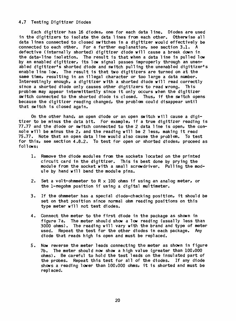
4. Connect the meter to the first diode in the package as shown in figure 7a. The meter should show a low reading (usually less than 3000 ohms). The reading will vary with the brand and type of meter used. Repeat the test for the other diodes in each package. Any diode that reads high is open and must be replaced.
5. Now reverse the meter leads connecting the meter as shown 1n figure 7b. The meter should now show a high value (greater than 100,000 ohms). Be careful to hold the test leads on the insulated part of the probes. Repeat this test for all of the diodes. If any diode shows a reading lower than 100,000 ohms, it is shorted and must be rep]aced.
20

-II-11-il-IIHIHIHIHI
hhhhhhr1-
K DIODE MODULE
o o
OHMMETER
END OFDIODE WITH
BLACK STRIPEOR BAND
LEADS REVERSED
4.7.4 TEST ILLUSTRATION A
HIHIHIHIHIHIHIHI
h1-1-h1-hh1-
O O _ [
OHMMETER
4.7.5 TEST ILLUSTRATION B
Figure 7. Electrical hookup for testing diodes.
21

6. When the modules are tested and repaired if necessary* reinstall them, making sure the modules are inserted with the striped ends of the diodes down. Installing a module upside down will cause bad data throughout the system.
7. If diode trouble is suspected or if any bad diodes have been found, the diodes in all the digitizers should probably be tested includ ing the headwater, tail water, gate, and lock-counter digitizers.
4.8 Testing Cables External to The Console
4.8.1 Using the Test Box at the Console
This test locates shorted cables. The symptom of a shorted cable is that the data on the recorder and the console display are larger than they should be. Make sure the console is working properly (section 4.2), then use the following procedure to find shorted cables:
1. Plug in the headwater, tailwater, and gate-digitizer plugs at the console (jacks Jl, J2, and J3).
2. Unplug all the digitizers (headwater, tailwater, gates, and lock counter) at the digitizer.
3. Connect the test box to the large cable of the lock-counter digi tizer in the top drawer of the console.
4. Put all the test box switches in the down, OFF, position.
5. Advance the display to channel 20. The display reading will depend on whether any lines are shorted to ground, and how many. If the display reads all zeros, no data line is shorted to ground. If a short is found, proceed to step 8. If there is no short, perform step 6.
6. Press the reset switch and then the advance switch until thedisplay-channel indicator indicates the lock-counter channel. (The advance switch must be held in continuously after the lock-counter channel is reached for the display to remain on long enough to be observed.) In sequence, switch the test-box toggle switches on and off, until all switches have been tried in both positions. If two data lines are shorted together and the switch for either of the shorted lines is turned on, the display will indicate the value of the two lines added together. If the shorted lines are associated with the same display digit, that is, if the 0.01 and the 0.04 data lines are shorted together, the display will reflect 0005. If two digits appear, the lines shorted together are data lines connected to separate digits. Thus, if the display reads 0802, the 8 line of the ones digit is shorted to the 0.02 line of the hundredths digit.
7. If this test doesn't reveal the cause of the problem, check the diodes in the digitizers. (See section 4.7.)
22
8. If a short is Indicated* the next task is to find the faulty cable. Unplug the head and tail water cables (jacks J2, J3) at the console. Only the gate cables now remain connected. Rerun the test. If a short is now indicated* the trouble is in the gate (Jl) cable. If there is no short, disconnect the gate cable and connect the head water cable. Rerun the test. If a short is indicated, the trouble is in the headwater cable. If there is no short, disconnect the headwater cable and connect the tail water cable. Rerun the test. If a short is indicated, it is in the tail water cable. Now proceed to section 4.8.3 to find the short in the suspect cable.
4.8.2 Using the Test Box at the Digitizer
This test is to find open data and enable lines. The symptom of an open data line is that the console is punching and displaying data values lower than the correct values. The symptom of an open enable line is the console displaying and punching 0000 data values. Make sure the console is working properly by performing the test outlined in section 4.2 before pro ceeding with this test.
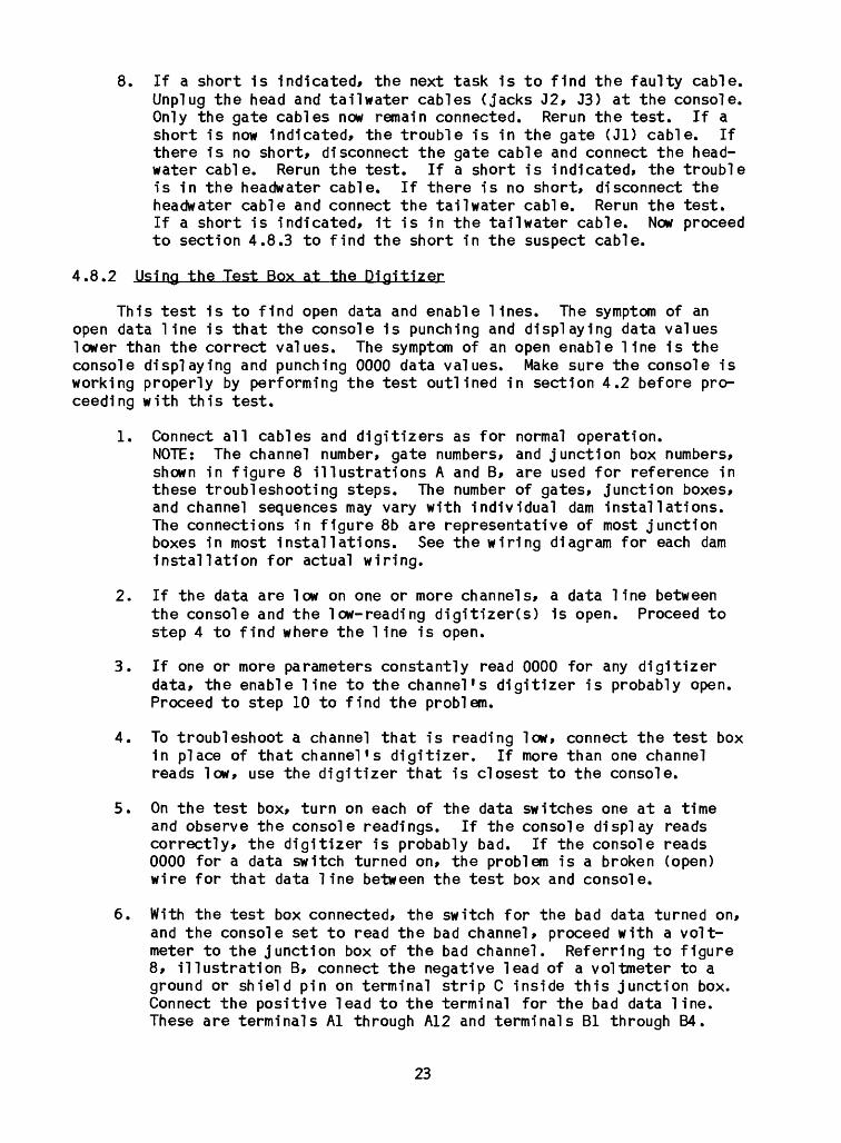
1. Connect all cables and digitizers as for normal operation.NOTE: The channel number, gate numbers, and junction box numbers, shown in figure 8 illustrations A and B, are used for reference in these troubleshooting steps. The number of gates, junction boxes, and channel sequences may vary with individual dam installations. The connections in figure 8b are representative of most junction boxes in most installations. See the wiring diagram for each dam installation for actual wiring.
2. If the data are low on one or more channels, a data line between the console and the low-reading digitizer(s) is open. Proceed to step 4 to find where the line is open.
3. If one or more parameters constantly read 0000 for any digitizer data, the enable line to the channel's digitizer is probably open. Proceed to step 10 to find the problem.
4. To troubleshoot a channel that is reading low, connect the test box in place of that channel's digitizer. If more than one channel reads low, use the digitizer that is closest to the console.
5. On the test box, turn on each of the data switches one at a time and observe the console readings. If the console display reads correctly, the digitizer is probably bad. If the console reads 0000 for a data switch turned on, the problem is a broken (open) wire for that data line between the test box and console.
6. With the test box connected, the switch for the bad data turned on, and the console set to read the bad channel, proceed with a volt meter to the junction box of the bad channel. Referring to figure 8, illustration B, connect the negative lead of a voltmeter to a ground or shield pin on terminal strip C inside this junction box. Connect the positive lead to the terminal for the bad data line. These are terminals Al through A12 and terminals Bl through B4.
23

GATE 5
ILLUSTRATION A
TYPICAL JUNCTION BOX CONNECTIONS
01 02 04 08 .1 .2 .4 .8 1 2 4 8
1 2 3 4 5 6 7 8 9 10 11 12
10 20 40 80
DATA LINES
CHANNELS 3-10
1 2 3 4 5 6 7 8 9 10 11 12
DATA LINES ENABLE LINES
CHANNELS 11-17 GROUND SHIELD
1 2 3 4 5 6 7 8 9 10 11 12
ENABLE LINES SHIELDS AND UNUSED WIRES
PIN NUMBER
PIN NUMBER
PIN NUMBER
ILLUSTRATION B
Figure 8. Diagram showing generalized electrical hookup at typical dam Installation.
24

For example, 1f the 20 line was bad, the voltmeter should be con nected to terminal B2.
7. If the reading Is more than 10 volts, the line to the console is good and the digitizer cable or plug is bad. If the reading is less than one volt, the trouble is in the cable toward the console.
8. Proceed to the next junction box closer to the console. Check the voltage at this junction box as in step 6. A reading of more than 10 volts indicates that the cable running toward the console is good, while the cable leaving the junction box (away from the con sole) has a broken (open) data line. A reading of less than one volt indicates that the break in the data line 1s in the cable toward the console.
9. Repeat step 8 until the section of cable that has the open enable line has been isolated. Replace or repair this section of cable as necessary. Refer to section 4.8.4 for further help in testing the bad section of cable.
10. To find an open enable line, replace the digitizer that Improperly reads 0000 with the test box. Set the test box to read 7777 (0.01, 0.02, 0.04, 0.1, 0.2, 0.4, 1, 2, 4, 10, 20, 40 switches are on). Observe the reading on the console for that channel. A reading of 0000 indicates that the enable line is probably open between the console and the test box. However, if the channel reads 7777, the digitizer that was removed is defective and should be replaced.
11. Set the console channel to the bad channel and the test box data to 0000 (all switches off). This causes all of the data lines in the system to go high and the enable line for the bad channel to go low.
12. Proceed with a voltmeter to the junction box nearest to where the test box is plugged in. Connect the voltmeter from Al (positive lead) to the enable line for the channel you are testing (fig. 8, illustration B). If the meter reads over 10 volts, the enable line to the console is good and the digitizer cable or plug is bad. If the meter reads less than one volt, there is a break in the enable line between the junction box with the voltmeter and the console.
13. Proceed to the next junction box (closer to the console). Check the voltage as in step 12. If the meter reads more than 10 volts, the enable line to the console is good. If the reading is less than one volt, the enable line is broken (open) between the junc tion box you are checking and the next one further away from the console.
14. Repeat step 13 until you find the section of cable with the open enable line. Replace or repair the cable as necessary. Refer to section 4.8.4 for further help in testing the cable.
25

4.8.3 Testing a Cable with an Qhmmeter for Shorts
Use the following test to locate a short in a cable.
1. Unplug all connectors (console and digitizers) on the suspect cable.
2. Set the volt-ohmmeter to the ohms position and select R x 100 ohms for an analog meter. Use the 10-kilohm scale for a digital meter.
3. Locate the cable wiring diagram for the installation under test.
4. Proceed to the console plug or the first junction box on the sus pect cab! e.
5. If a previous test or the symptom has indicated which lines may be shorted* connect the ohmmeter across those lines. If a reading of less than 10*000 is found* proceed to step 8. A reading of more than 10*000 indicates these lines are not shorted. Go to step 6 to test the other lines.
6. Connect the black (-) lead of the ohmmeter to the 0.01 line; touch the red (+) lead to each higher numbered line in sequence, that is 0.02* 0.04* etc. If the meter indicates a reading of less than 10*000 across any pair of the lines, a short has been found. In that event* proceed to step 8. An exception is the ground lines which are tied together in the console plug and the gate junction boxes. The meter will read a short when connected across any two of these 1ines.
7. Move the black lead to the 0.02 line. Repeat the step 6 process until all combinations of lines have been tried. If all combina tions reveal no shorts, refer to table 2 to determine what test to try next.
8. With the ohmmeter leads across the shorted lines, read the meter carefully. If the meter reads low on its scale, change the range switch so that the meter can be read more accurately. If the read ing is low (less than 100 ohms), there is probably a direct short. If the reading is higher than 100 ohms or unstable, the problem may be water in the cable, junction box, or digitizer plug.
9. Try measuring the short at several junction boxes along the cable and carefully note the ohmmeter readings. The location with the lowest reading should be closest to the short.
10. If the problem is in a gate cable, go to a junction box halfway down the line of gates and disconnect the shorted leads from the terminal strip. Take an ohmmeter reading on the wires leading to the console and then on the wires going farther out on the dam. The short is on the side that has the lowest ohms reading.
26

11. Now proceed to a junction box halfway down the shorted side of the cable. Again, disconnect the shorted leads from the terminal strip and take ohmmeter readings on the wires as before. The short lies on the side that has the lowest ohms reading.
12. Repeat step 11 until the shorted section of cable has been iso lated. Repair or replace this section of cable as necessary. Before operating the console, reconnect all wires that were removed from terminal strips in the preceeding tests.
4.8.4 Testing a Cable with an Qhmmeter for Open Wires
Use the following test to locate open wires in a cable.
1. Unplug all connectors on the suspect cable.
2. Set the ohmmeter to the ohms position. Select R x 100 ohms for an analog meter and the 10-kilohm scale for a digital meter.
3. Locate the wiring diagram for the cable being tested.
4. At one end of the suspect cable, short any two data lines together. If the cable has a connector on that end, pick two adjacent pins (marked either A and B, or 1 and 2). If the cable does not have a connector, note the colors of the two wires (lines) that are being shorted. If the cable has a connector, refer to the wiring diagram to see where and/or how the wires that are being shorted terminate at the other (distant) end of the cable. At the distant end of the cable, connect the ohmmeter to the two wires that are shorted together. If the two wires are good (not open), some relatively low value of resistance will be reflected by the ohmmeter (usually less than 100 ohms). This is because the type of wire used in cables for dam installations has an electrical resistance of approximately 15 ohms per thousand feet.
Either of the two wires shorted in the foregoing test sequence can now be shorted in turn with all other wires in the cable. The shorting is done at one end of the cable with the ohmmeter connected in turn to each pair being tested at the other end of the cable. If the ohmmeter reflects a low ohms reading, the tested pair is good. Make an ohmmeter check at each gate- digitizer plug to ensure that all branch cables are good (fig. 8a). The basic method of first finding two good wires in a cable system and then using either of these good wires to individually check all other wires is applicable to any cable or cable system.
27

4.9 Testing the Lock Counter
4.9.1 Using the Lock-Counter Test Cable
The following test is used to determine whether or not the lock-counter circuitry within the console is operating properly.
1. Remove the lock pressure-switch cable plugs from jacks J5 and/or J6 on the main console.
2. Plug the test cable (with the switch in the off position) into jack J5.
3. Wait at least 2-1/2 minutes before proceeding with step 4.
4. Note the number on the mechanical counter inside the lock-counter digitizer.
5. Switch the lock-test cable switch to on.
6. Observe the lock-digitizer count and the time. The digitizer count should advance by one within 1/2 to 2-1/2 minutes from the time the lock switch was turned on. If it does not advance* proceed to step 15.
7. After the lock-digitizer count advances by one in step 6, turn the lock test-cable switch off.
8. Observe the lock-digitizer count and the time. The digitizer count should once again advance by one within 1/2 to 2-1/2 minutes. If the lock-digitizer count does not advance, go to step 15.
9. Move the test cable from jack J5 on the rear of the console to jack J6 making sure the test-cable switch is off.
10. Note the count on the lock digitizer.
11. Switch the lock-counter test-cable switch to on.
12. Observe the lock-digitizer count and the time. The digitizer count should advance by one within 1/2 to 2-1/2 minutes from the time the lock switch was turned on. If it does not advance, go to step 15.
13. Switch the lock test-cable switch off.
14. Observe the lock-digitizer count for 2-1/2 minutes. No further counts should take place. Note that the J6 input only counts when the test switch is turned on, while the J5 input counts for both turning on and turning off the test switch.
28

15. If Incorrect operation was observed 1n any of the above steps, the lock-counter digitizer or the lock-counter circuit 1s defective. Make sure that the 4-p1n plug on the side of the digitizer 1s con nected. Check the solenoid Inside the digitizer for possible bind ing. The plunger on the solenoid can be pushed 1n by hand, and the digitizer should count when it 1s released. Next try replacing card 9, which contains the lock-counter circuitry. (See section 4.4 for card-changing directions.) If the problem still persists, check the console card-rack wiring as described in section 4.5.
4.9.2 Testing the External Lock Cable and Switch
This test is used to determine whether the lock cable or the lock switch is shorted or open.
1. The following tests are made on the external lock-counter plugs and cables while they are disconnected from jacks J5 and J6 on the rear of the console.
2. Connect an ohmmeter between pins 1 and 2 of the plugs on the cable coming from the lock-pressure switch.
3. The pressure switch should be closed 1f the lock is empty and open if the lock is full. The ohmmeter should show continuity (less than 100 ohms) 1f the lock is empty and Infinity (over 10,000 ohms) if the lock 1s full.
4. Operate the lock switch and observe the ohmmeter for the correct reading as described in step 5. The lock switch can be operated manually by pressing on the diaphragm, raising and lowering 1t in the water, or by draining and filling the lock with the switch installed. Be sure to test the switch at least once 1n each posi tion.
5. Connect the ohmmeter from pin 3 to pin 2. The meter should Indi cate more than 10,000 ohms. Now check from pin 1 to pin 3. The meter should Indicate more than 10,000 ohms. If less than 10,000 ohms is read, the cable either has a short from the conductor to the shield or water has penetrated the cable. Repair or replace as necessary.
6. If your Installation has two locks, repeat the above test on the other lock f s cable starting with step 2.
29

4.10 The Recorder-Brake Circuit
The recorder-brake circuit 1s on a small circuit board attached to the recorder's terminal strip. This circuit causes the recorder motor to be electronically braked when power 1s removed from the recorder motor. If this circuit falls, the recorder could coast with power removed Into the beginning of the next punch cycle. Later, when the next punch cycle starts, the recorder will be ahead of where 1t should be causing some of the data (usually the time punch) to be missed. A bad brake will also cause the recorder's punch cycle to have an Irregular sound with the recorder pausing between punches. Check the brake as described in the following section.
4.10.1 Testing the Recorder Brake
1. Run the console through a punch cycle.
2. Look at the mlcroswltch that rides on the recorder's cam. Therecorder should stop with the switch's actuator on the high part of the cam, and the actuator should be no more than three-sixteenths of an Inch from the edge of the cam's notch. If the recorder did not stop within the specified three-sixteenths of an Inch, replace the brake circuit.
30

APPENDIX
Schematic diagrams of cards 1, 5, 9, 13, 15, 17, and 21
31
(p.

Card 1
APPENDIX33

*d *d
W
NO
.N
AM
EM
AT
-R
EM
AR
KS
tx!
cLO
Ck
ENAB
LE
5I6-
NJA
L
00
^
£t
'^}
- -
UN
LES
S O
THER
WIS
E SP
ECIF
IED
DIM
EN
SIO
NS
AR
E IN
IN
CH
ES
TO
LER
ANC
ES O
N F
RA
CT1
0NS
±l/6
4 D
EC
IMA
LS±.
010
AN
GLE
S±0
«-30
' D
O N
OT
SCAL
E TH
IS D
RAW
ING
UN
ITE
D
STAT
ES
DE
PA
RTM
EN
T O
F TH
E IN
TER
IOR
GE
OLO
GIC
AL
SU
RV
EY
CA
KD
T
n

NO
.
U)
DU
MM
Y C
HA
NN
EL
EN
AB
LE L
INE
TO
C
AK
D13
O VD
i.fk
1C 4,r
,6 -
4t"
> 7
P
IN
It-V
i,
PIN
1=
rt'O
i.rj
, P
IN
S -G
-L1
C
1,3
.1=
4041
FIN
S
PtN
9
'ff-
J.
1C
SOCK
ETS
DIO
DE
S A
«£ 5
WA
PU
ED
ft3
« B
ITS
' IB
5IR
S.O
tN
D
un
*? C
HA
NN
EL.
D
IOD
ES
* 1
N4
14
8
LOCK
5'A
ITC
H
LOCN
SO
LEN
OID
y ;
iM L
O:K
UN
ITE
D
STA
TES
D
EP
AR
TME
NT
OF
THE
IN
TER
IOR
GE
OL
OG
ICA
L
SU
RV
EY
LOC
k C
OU
NTE
R
CIR
CU
ITU
NLE
SS O
THER
WIS
E SP
ECIF
IED
DIM
ENSI
ON
S AR
E IN
IN
CH
ES
TO
LER
AN
CES
ON
FR
AC
TIO
NS
±l/6
4 D
EC
IMA
LSt.O
lO
AN
GL
ES
tO'-M
1 D
O N
OT
SCAL
E TH
IS D
RA
WIN
G

Card 13
APPENDIX36

NO
.N
AM
EM
AT.
|QUA
N|
REMA
RKS
W
U)
-J
UN
LESS
OTH
ERW
ISE
SPEC
IRED
DIM
ENSI
ON
S AR
E IN
IN
CH
ES
TOLE
RA
NC
ES O
N F
RA
CTI
ON
Stl/
64
PE
CIM
ALS
t.010
A
NG
LES
tO'-S
O*
DO
NO
T SC
ALE
THIS
DR
AW
INQ
DIP
T
Y'E
IF>,
OC6
^n
o 03
I-J a.
NO
. I
NA
ME
MA
T.
IQU
AN
I
RE
M.
UN
ITE
D
STA
TES
D
EP
AR
TM
EN
T O
F T
HE
IN
TER
IOR
GE
OLO
GIC
AL
SU
RV
EY

NO
.N
AM
EM
AT.
|QUA
N|
REMA
RKS
w X!
U) o>
fclT
10
PIC
ITIZ
EF
5 / 30
,
-- I
. I, J
,>
4 C/.A
D 1
5
.;
LIK
E N
SS
>-^
S1u
@
0
53
J"
Cflf
lDS
5"
AN
D
f
TE
iEM
FT
fy
XINO
,\m
vt.iT
four
pur
PIN
J
OP
TIC
AL
CJy
^>l£
K3
= M
C7
-2
MC
T-a DI
P
UN
LES
S O
THER
WIS
E SP
ECIF
IED
DIM
EN
SIO
NS
ARE
IN
IN
CH
ES
TO
LER
ANC
ES O
N F
RA
CT
ION
Stl/
64
OE
CIM
ALS
l.010
A
NG
LES
tO'-S
O1
DO
NO
T SC
ALE
THIS
DR
AWIN
G
NO
- I
NA
ME
I
MA
T.
IQ
UA
N.
I R
EM
.
DE
PA
RTM
EN
T O
F TH
E
INTE
RIO
R_
__
_
GE
OLO
GIC
AL
SU
RV
EY
__
__
__
DA
T*
C^/
'P
O CX
I 1
^J

Card 21
APPENDIX39