1969 , volume , issue feb-1969 - about hp labs · they respond in less than one microsecond to...
TRANSCRIPT

HEWLETT-PACKARD JOURNAL
FEBRUARY 1969 © Copr. 1949-1998 Hewlett-Packard Co.

First in a l ine of sol id-state display devices are these one- and three-digi t numeric ind icators. Compat ib le wi th in tegrated c i rcu i ts , they need only BCD input s ignals and five-volt power to display any numeral from 0 to 9 in an array of bright red dots.
Solid-State Displays By Howard C. Borden and Gerald P. Pighini
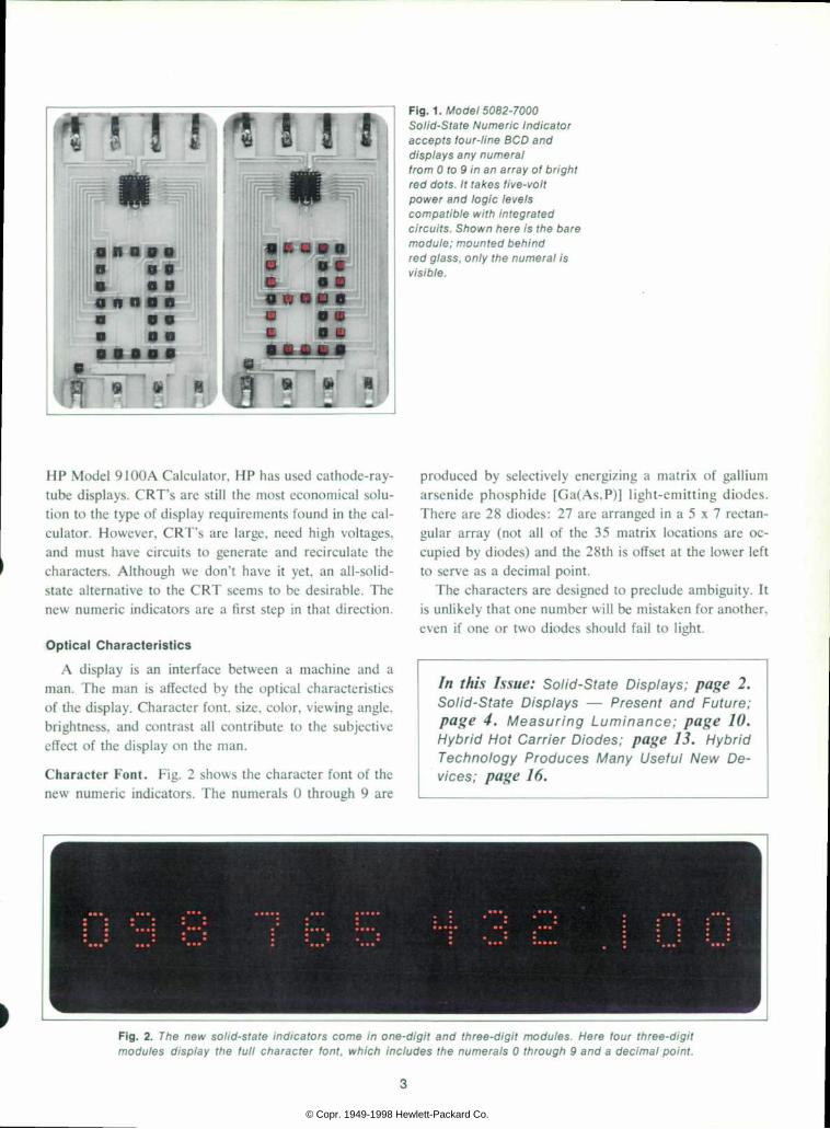
SOLID-STATE DISPLAYS ARE HERE. Developing them has taken more than six years of research and development in light-emitting materials, plus Hewlett-Packard's re sources in solid-state technology, integrated-circuit de sign and manufacture, ceramic metallization and etching, and optoelectronic packaging. The result is the new HP Model 5082-7000 Numeric Indicator, a small, low- power, all-semiconductor module which accepts four- line binary-coded-decimal input signals and displays the corresponding digit, 0 through 9, as an array of brightly glowing red dots (Fig. 1). A similar but larger module, Model 5082-7001, displays three digits in line.
Compatibility with integrated circuits is a significant advantage of the new solid-state indicators over other types of display devices. They need only five-volt power and logic levels of 0 and 5 volts (nominal), compatible with transistor-transistor logic (TTL) and diode-transistor logic (DTL).
1C compatibility, in fact, was the prin cipal motivating factor in the development of the solid-state display. However, i t wasn't the only one. The list of advantages of sol id-state displays is impressive. Among them are thin single-plane presen tation, ruggedness, and high 'solid-state' reliability. Because they are free from fun damental degradation mechanisms, they are expected to have long life. They don't generate RFI, and they are amenable to low-cost, high-volume production using
semiconductor batch fabrication techniques. The new solid-state indicators have other advantages
as well. They have a surface light distribution which gives constant brightness over wide viewing angles. They have high contrast and color purity, both of which con tribute to readability. They are free from parallax be cause they produce all numerals in the same plane, and they respond in less than one microsecond to input-code changes; hence they are useful as readout devices when test results are being photographed with high-speed cam eras. The brightness of the solid-state indicators is volt age-variable; it can be adjusted for optimum readability under widely varying ambient light conditions.
Obvious uses of the new indicators are in instrument panels, status boards, and in formation displays, or anywhere a need exists for a compact, IC-compatible, vari able-brightness readout module that can perform both the decoding function and the readout function. The possibilities for these indicators and for future solid-state displays are intriguing; some are discussed on page 4.
Itself an instrument manufacturer, Hew lett-Packard may eventually become its own best customer for solid-state read outs, especially where a large character font is needed. Limited character font is a disadvantage of gaseous display tubes. Where greater flexibility in alpha-numeric and symbolic display is needed, as in the
P R I N T E D I N U . S . A .
© Copr. 1949-1998 Hewlett-Packard Co.
*S I ! !
o n a o
«« l i l i D 9 9 a v L O
" Ã"! : !
Fig . 1 . Model 5082-7000 So l i d -S ta te Numer i c I nd i ca to r accep t s f ou r - l i ne BCD and d i sp lays any numera l f rom 0 to 9 in an ar ray o f b r igh t red dots . I t takes f ive-vo l t p o w e r a n d l o g i c l e v e l s compa t i b l e w i t h i n t eg ra ted c i r cu i t s . Shown here i s the bare m o d u l e ; m o u n t e d b e h i n d red g lass , on ly the numera l i s v is ible.
HP Model 9100A Calculator, HP has used cathode-ray- tube displays. CRT's are still the most economical solu tion to the type of display requirements found in the cal culator. However, CRT's are large, need high voltages, and must have circuits to generate and recirculate the characters. Although we don't have it yet, an all-solid- state alternative to the CRT seems to be desirable. The new numeric indicators are a first step in that direction.
Optical Character ist ics
A display is an interface between a machine and a man. The man is affected by the optical characteristics of the display. Character font, size, color, viewing angle, brightness, and contrast all contribute to the subjective effect of the display on the man.
Character Font. Fig. 2 shows the character font of the new numeric indicators. The numerals 0 through 9 are
produced by selectively energizing a matrix of gallium arsenide phosphide [Ga(As,P)] light-emitting diodes. There are 28 diodes: 27 are arranged in a 5 x 7 rectan gular array (not all of the 35 matrix locations are oc cupied by diodes) and the 28th is offset at the lower left to serve as a decimal point.
The characters are designed to preclude ambiguity. It is unlikely that one number will be mistaken for another, even if one or two diodes should fail to light.
I n t h i s I s s u e : S o l i d - S t a t e D i s p l a y s ; p a g e 2 . S o l i d - S t a t e D i s p l a y s - - P r e s e n t a n d F u t u r e ; p a g e 4 . M e a s u r i n g L u m i n a n c e ; p a g e 1 0 . H y b r i d H o t C a r r i e r D i o d e s ; p a g e 1 3 . H y b r i d T e c h n o l o g y P r o d u c e s M a n y U s e f u l N e w D e v ices ; page 16 .
Fig. three-dig i t Here new sol id-state indicators come in one-dig i t and three-dig i t modules. Here four three-dig i t m o d u l e s p o i n t . t h e f u l l c h a r a c t e r f o n t , w h i c h i n c l u d e s t h e n u m e r a l s 0 t h r o u g h 9 a n d a d e c i m a l p o i n t .
3
© Copr. 1949-1998 Hewlett-Packard Co.

Solid-State Displays, Present and Future
T h e n e w o n e - d i g i t a n d t h r e e - d i g i t s o l i d - s t a t e n u m e r i c i n d i c a t o r s a r e o n l y a b e g i n n i n g . L a r g e r a n d s m a l l e r c h a r a c t e r s , l a r g e r c h a r a c t e r s e t s , m o r e c o l o r s , a n d d i s c r e t e l i g h t s o u r c e s a r e u n d e r d e v e l o p m e n t . D i f f e r e n t k i n d s o f d i s p l a y s a r e i n t h e f u t u r e .
Using What's Available Now
S m a l l s i z e , l o w p o w e r , l o w v o l t a g e , a n d h i g h b r i g h t n e s s m a k e t h e p r e s e n t l y a v a i l a b l e 1 / 4 i n c h n u m e r i c i n d i c a t o r s s u i t a b l e f o r a w i d e r a n g e o f a p p l i c a t i o n s i n c o m m e r c i a l a n d m i l i t a r y e q u i p m e n t . D i s p l a y s w i t h a s m a n y 2 5 0 t o 2 7 5 c h a r a c t e r s p e r s q u a r e f o o t c a n b e a s s e m b l e d u s i n g o n e - d i g i t a n d t h r e e - d i g i t m o d u l e s . A n o b v i o u s u s e i s f o r n u m e r i c r e a d o u t s f r o m i n s t r u m e n t s a n d e l e c t r o n i c d a t a p r o c e s s i n g e q u i p m e n t . I n t e l e m e t e r e d o r c o m p u t e r - d r i v e n s t a t u s b o a r d s , t h e m o d u l e s ' s m a l l b u l k a n d h i g h i m a g e d e f i n i t i o n s h o u l d p r o v e v a l u a b l e . T h e n u m e r i c i n d i c a t o r s h a v e n o s e a l e d - i n t o x i c g a s e s a n d o p e r a t e a t l o w v o l t a g e s , a n d s o a r e p a r t i c u l a r l y w e l l s u i t e d f o r c l o s e d e n v i r o n m e n t s , o r f o r e n v i r o n m e n t s w h e r e t h e r e a r e e x p l o s i o n h a z a r d s . T h e i r r e d c o l o r m a k e s t h e m u s e f u l f o r d i s p l a y s i n d a r k r o o m s o r i n a r e a s w h e r e p e r s o n n e l m u s t b e d a r k - v i s i o n a d a p t e d .
Color TV Still Years Away
A l t h o u g h i t w i l l s u r e l y h a p p e n , p e r h a p s a n o t h e r t e n y e a r s w i l l p a s s b e f o r e s o l i d - s t a t e d i s p l a y t e c h n o l o g y i s s u f f i c i e n t l y a d v a n c e d t o m a k e a w a l l - m o u n t e d c o l o r t e l e v i s i o n s e t p r a c t i c a l . R e d , b l u e , a n d g r e e n l i g h t - e m i t t i n g d i o d e s w i l l b e n e e d e d t o p r o d u c e t h e v i s i b l e s p e c t r u m w i t h a c c e p t a b l e c o l o r f i d e l i t y , a n d a t p r e s e n t w e l a c k t h e m e a n s f o r p r o d u c i n g t h e b l u e o n e s . C o s t i s a n o t h e r p r o b l e m . A b o u t a q u a r t e r - m i l l i o r p o i n t s w o u l d b e n e e d e d f o r a s t a n d a r d T V p r e s e n t a t i o n . A t t o d a y ' s p r o d u c t i o n c o s t s , t h e c h i p s a l o n e w o u l d c o s t n e a r l y $ 2 5 , 0 0 0 f o r a f i v e - i n c h - w i d e s c r e e n . P o w e r r e q u i r e m e n t s a r e a l s o a p r o b l e m . A f i v e - i n c h - w i d e
s c r e e n , 2 5 % s a t u r a t e d t o a l u m i n a n c e o f 7 5 f o o t l a m b e r t s , w o u l d n e e d a b o u t 1 0 0 w a t t s . A s q u a r e f o o t o f d i o d e s d r i v e n s o l i d l y t o a b r i g h t n e s s o f 5 0 f o o t l a m b e r t s w o u l d d r a w a b o u t o n e k i l o w a t t , a t t h e e l e c t r o l u m i n o u s e f f i c i e n c i e s t h a t a r e t y p i c a l o f t o d a y ' s m a t e r i a l s . F o r a l l t h e s e r e a s o n s , a s o l i d - s t a t e c o l o r T V s e e m s t o b e y e a r s a w a y .
What About the Near Future? S o m e w h a t n e a r e r t o r e a l i t y t h a n s o l i d - s t a t e t e l e v i s i o n d i s p l a y s a r e s m a l l e r s o l i d - s t a t e c h a r a c t e r s a n d s y m b o l s w h i c h c a n b e i n c o r p o r a t e d i n p r o b e s , m i c r o m e t e r s , a n d o t h e r t o o l s , s o t h e t o o l s t h e m s e l v e s w i l l b e c o m e d i g i t a l m e a s u r i n g i n s t r u m e n t s . S m a l l d i s p l a y s c a n a l s o b e h e a d m o u n t e d , s a y i n a p i l o t ' s h e l m e t . C h a r a c t e r d e n s i t i e s o f 5 0 , 0 0 0 t o 2 5 0 , 0 0 0 c h a r a c t e r s p e r s q u a r e f o o t a r e f e a s i b l e , t h e s i z e r e d u c t i o n b e i n g l i m i t e d o n l y b y t h e h u m a n s i d e o f t h e m a n - m a c h i n e i n t e r f a c e .
S m a l l d i s p l a y s a r e p o t e n t i a l l y u s e f u l a s m a r k e r s i n o p t i c a l i n s t r u m e n t s , t o o . O n e s u c h a p p l i c a t i o n a r i s e s w h e n r e c o r d i n g d a t a o n f i l m . A n 1 8 x 3 2 d o t p a t t e r n i s s o m e t i m e s u s e d t o i d e n t i f y f r a m e s f o r a u t o m a t i c s c a n n i n g e q u i p m e n t . W i t h t h e i r n a n o s e c o n d t u r n - o n a n d t u r n - o f f t i m e s , l i g h t - e m i t t i n g d i o d e s c o u l d e a s i l y s u p p l y t h e d o t p a t t e r n , w h i c h c o u l d t h e n b e t r a n s m i t t e d t o t h e f i l m b y f i b e r o p t i c s .
Alphanumeric Modules Are Imminent A l m o s t r e a d y f o r p r o d u c t i o n a t H P a r e a l p h a n u m e r i c i n d i c a t o r s w h i c h u s e t h e s a m e 5 x 7 d o t m a t r i x a s t h e n e w n u m e r i c i n d i c a t o r s , w i t h a l l 3 5 p o s i t i o n s i n t h e m a t r i x o c c u p i e d b y d i o d e s . S i x - b i t A S C I I c o d e c o n t r o l s t h e i n d i c a t o r s . T h e c h a r a c t e r f o n t , i l l u s t r a t e d b e l o w , i n c l u d e s t h e l e t t e r s A t h r o u g h Z , t h e d i g i t s 0 t h r o u g h 9 , a n d t h e s y m b o l s + , - , ) . ( , â € ¢ , â € ¢ , ? , = , / , a n d . . T w o i n t e g r a t e d - c i r c u i t c h i p s d e code t he i npu t s and d r i ve t he d i odes . The IC ' s a re des i gned s o t h e y c a n b e m o d i f i e d e a s i l y a n d e c o n o m i c a l l y w h e n e v e r a change o f f on t i s wan ted .
© Copr. 1949-1998 Hewlett-Packard Co.

Character Size. The characters are 1A inch high. How ever, because of an unexplained subjective phenomenon, the characters appear larger by at least 50%. The ap parent character height is about 3/s to l/2 inch. This phenomenon isn't visible in the photographs in this arti cle, so the reader should be aware when looking at these photographs that a 'living display' would have a substan tially different subjective effect. After a study of larger and smaller sizes in various display applications, it was decided that V4 inch characters are quite satisfactory for general instrumentation display, and this size was selected for the initial products. People with normal vision can read the characters at distances up to 8 feet.
Both the one-digit and the three-digit indicators are intended primarily for mounting in a horizontal line. The minimum center-to-center spacing between characters in separate modules is limited by the package width to 0.570 inch. Within the three-digit module the character spacing is 0.400 inch, center-to-center. The minimum vertical center-to-center spacing is slightly more than one inch. Large displays in which each character is individ ually replaceable can be constructed out of one-digit modules; such displays can have as many as 250 char acters per square foot.
Color. The color of the light emitted by the numeric indicators is red. It has a dominant wavelength of 655 nm and is of high purity. Although alloys of gallium, arsenic, and phosphorus can be made to emit any color between infrared and green, the luminance (i.e., visual brightness) of HP's Ga(As,P) alloy is greatest, for a given input energy, when the light has a wavelength of 655 nm. Red is also well suited for use in darkrooms, ready rooms, and other dark environments, since it impairs the eye's dark-adaptation considerably less than other colors.
Brightness. Typical Ga(As,P) diodes used in the nu meric indicators produce luminances of 75 footlamberts with 4.0 Vdc applied to the module. At 50 fL bright ness, the characters appear quite bright under normal factory lighting. Brightness can be varied between 5 and more than 50 footlamberts by adjusting the dc voltage applied to the 'LED-)-' terminal of the module. As shown in Fig. 3, the luminance variation is nearly linear from three to four volts.
Reduced display brightness is desirable in dark rooms, or where power is at a premium. The power input to the light-emitting diodes varies roughly linearly with LED-)- voltage, as does the power dissipated in the current-limiting circuits in the module. Power to the logic circuits in the module remains constant at about 1 50 mW.
LED + TERMINAL VOLTAGE (Volts)
F i g . 3 . T h e b r i g h t n e s s o f t h e s o / i d - s t a t e i n d i c a t o r s c a n b e a d j u s t e d b y v a r y i n g t h e v o l t a g e a p p l i e d t o t h e L E D + te rm ina l o f t he modu le . Va r i ab le b r i gh tness and red co lo r make the i nd i ca to rs use fu l i n da rk wo rk ing env i ronmen ts .
Contrast. Contrast is the ratio of the luminance of a lighted diode to the luminance of the surrounding area, which in this case is a white ceramic substrate with gold metallic striping. For optimum contrast, the numeric in dicators should be viewed through a red 'notch' filter. (The the isn't supplied with the indicators.) Ideally, the filter should transmit 100% of the red light from the diodes (density = 0) and 0. 1 % or less of the rest of the visible spectrum (density > 3.0). Rohm and Haas' Plexi glás #2423 as it is presently manufactured isn't quite this good, but it is effective and inexpensive.
Viewing Angle. There are two general display situa tions. One is typified by bench-mounted instruments; here wide viewing angle is important, either so several instru ments can be observed by one operator, or so a group of people can observe the same display. In such applica tions the new numeric indicators can be viewed from angles as great as 60° from the normal in a horizontal plane and as great as 70° in a vertical plane. They have a cosine, or Lambertian, surface light distribution, mean ing their light is equally dispersed in all directions; this makes their brightness independent of viewing angle.
The second display situation is typified by an aircraft instrument panel, where the observer's head is in a rela tively fixed position with respect to the display. In these situations it's often desirable to trade off wide-angle view- ability for minimized light reflection or for the higher
© Copr. 1949-1998 Hewlett-Packard Co.

F i g . 4 . M o d e l 5 0 8 2 - 7 0 0 0 S o l i d - S t a t e N u m e r i c I n d i c a t o r s c o n s i s t o f 2 8 g a l l i u m a r s e n i d e p h o s p h i d e r e d - l i g h t - e m i t t i n g d i o d e s a n d a n 1 C c h i p c o n t a i n i n g s o m e 4 0 0 c i r c u i t e l e m e n t s , a l l m o u n t e d o n a c e r a m i c s u b s t r a t e a n d s e a l e d i n a c a s e d e s i g n e d f o r w i d e - a n g l e v i e w - a b i l i t y . O n t h e s u b s t r a t e i s a m e t a l i n t e r c o n n e c t i o n p a t t e r n .
efficiency possible with narrow-lobe light emission. The radiation pattern of the numeric indicators can be modi fied by appropriate filters, lenses, and shades.
Electr ical Character ist ics
While the optical characteristics oà the man/machine interface are important to the man, the machine is more interested in the electrical characteristics of the display.
Each digit of the solid-state indicators has eight inputs.
Table I. Binary Code Truth Table
N o t e : N e g a t i v e L o g i c ' 0 ' = L i n e H i g h : 3 . 5 < V < 5 0 ' V - L i n e L o w : 0 . 0 < V < 1 . 5
They are: • one line for a 5 Vdc filtered power supply for inte-
grated-circuit logic operation. This supply should be regulated to prevent overvoltage conditions and should be able to provide about 30 mA per digit.
• one line (LED+) for a 4.0 Vdc light-emitting-diode power supply, capable of providing up to 200 mA per digit. If brightness variation is required, this supply should be variable from about 2.0 to 4.0 volts.
• four lines for 8-4-2-1 BCD negative logic, 3.5 V < '0 ' < 5 .0 V, 0 V < T < 1.5 V The BCD coding, Table I, conforms to ASCII coding.
• one line for decimal point control. A 10 mA, current- limited source is needed. It is turned on to illuminate the decimal point.
• one line for ground, common to all signals and power supplies. The decoding circuitry has no memory, so the display
will conform to the input code within less than a micro second — typically less than 200 ns. The modules also have no overvoltage protection. Transients exceeding 6 V on the BCD lines or the integrated-circuit power- supply lead, or exceeding 5 V on the LED+ lead, may cause damage, so protection should be provided.
Mechanical and Thermal Character ist ics
At 50 f L average diode brightness, and with the num bers 5 or 8 illuminated (17 diodes lighted), the light- emitting diodes dissipate about 250 mW. Another 250
• The source supp ly may a lso be a fu l l -wave- rec t i f ied un f i l te red source o f f requency 5 0 H z f l i c k e r o b L o w e r f r e q u e n c i e s c a n b e u s e d i f n o t i c e a b l e f l i c k e r i s n o t o b ject ionable.
© Copr. 1949-1998 Hewlett-Packard Co.

mW is dissipated by the decoding circuitry. Hence the modules are rated at Ã/2 watt per digit. Heat sinking should be adequate to dissipate this amount of power with a temperature rise of 10°C or less above ambient.
In mounting the display modules, care should be taken to protect their glass front windows. The indicators don't need a vacuum, so they'll continue to operate even with substantial package damage. However, the hermetic seal will be lost if the front window is broken, and this may reduce the life of the module.
The leads of the indicator modules are 0.100 inch apart, compatible with current printed-circuit-board practice.
How They ' re Made
Five basic elements make up the one-digit solid-state numeric indicators, as shown in the exploded diagram Fig. 4. All the parts except the case are manufactured by Hewlett-Packard. Tekform Products Company manu factures the case. The five elements are: • A ceramic substrate. The front of the substrate is thin-
film metallized and photolithographically etched to form an interconnection pattern consisting of 8 input pads and 1 8 output drive lines. The back of the sub strate is also metallized so the thermal resistance be tween the substrate and the case will be low.
• Twenty-eight gallium arsenide phosphide red-light- emitting diode chips. Twenty-seven are arrayed in a 5 x 7 matrix and one is offset to serve as a decimal point. The cathodes of the diodes are bonded to the metal interconnection pattern on the substrate. The light is emitted from the anode side of the diodes. All of the anodes are wired togther and connected to the metal lized substrate by ultrasonic lead bonding, using 0.001 inch aluminum wire.
• A monolithic silicon integrated-circuit chip. The chip translates standard 8-4-2-1 binary-coded-decimal in put codes into 18 current-limited outputs which drive the 27 diodes in the 5 x 7 matrix. (A separate external source drives the decimal point.) The 1C chip has only 18 outputs because certain combinations of the 27 diodes are always lighted together. The 1C terminals are connected to the metal layer on the substrate by ultrasonic bonding, using 0.001 inch aluminum wire.
• A tin-plated Kovar case with glass-to-metal-sealed leads. The case is designed for wide-angle readability of the characters. The ceramic substrate is soldered to the case.
® West inghouse Electr ic Corporat ion
• A glass window cover whose coefficient of thermal ex pansion is matched to that of the case. The glass is joined to the case with epoxy to form a hermetic seal.
Ga(As.P) Light-Emit t ing Diodes
Each light-emitting diode chip is a simple mesa struc ture (see Fig. 5). An n-type alloy of gallium arsenide phosphide is grown epitaxially on a gallium arsenide sub strate. The p region is then diffused and capped with a comb-type metal anode. The comb-type anode distributes the diode current evenly over the diode's cross-section while masking less than 25% of the light.
When forward bias is applied to the diode, the poten tial barrier at the junction is reduced so current can flow. Electrons are injected into the p region and holes are injected into the n region. Eventually these minority car riers recombine, and in some of the recombinations energy is given off as photons. Most of the light is gener ated in a space charge layer about 0.5 /on wide on the p side of the junction, where several percent of the re combinations result in near-edge photons — that is, pho tons whose energy is near the bandgap energy.
Since the anode surface is very close to the junction, most of the light generated internally reaches the surface. However, only a few percent of the photons escape. The loss is caused by internal surface reflection, which is a result of the difference between the refractive index of the Ga(As,P) alloy (n sr 3.5) and that of its surround ings (n s; 1.0).
F i g . 5 . E a c h l i g h t - e m i t t i n g d i o d e c h i p i s a m e s a - t y p e p - n j u n c t i o n d i o d e . L i g h t i s g i v e n o f f i n r e c o m b i n a t i o n s o f m i n o r i t y c a r r i e r s , p r e d o m i n a n t l y o n t h e p s i d e o f t h e  ¡ u n c t i o n . T h e c o m b a n o d e g i v e s e v e n c u r r e n t d i s t r i b u t i o n w h i l e b l o c k i n g l e s s t h a n 2 5 % o f t h e l i g h t .
© Copr. 1949-1998 Hewlett-Packard Co.
125
1.00
R E L A T I V E 0 . 7 5 ELECTROLUMINOUS
E F F I C I E N C Y 0 5 0
0.25
Band Gap Energy (eV) °
Compos i t ion GaAs , . ,? , ( x ) 0 .3 I
W a v e l e n g t h ( n m ) 7 0 0
2.0 J _ 0 . 5
- O r a n g e -
£.1
- Y e l l o w
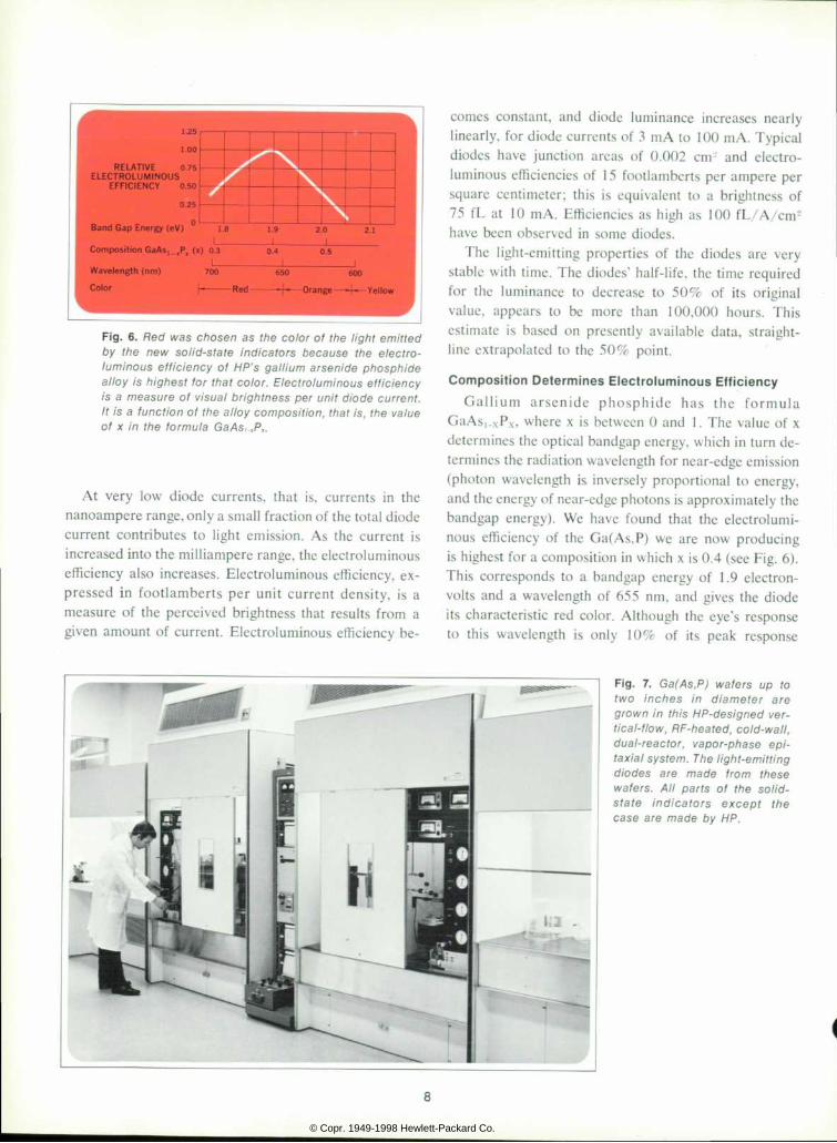
F i g . 6 . R e d w a s c h o s e n a s t h e c o l o r o f t h e l i g h t e m i t t e d b y t h e n e w s o l i d - s t a t e i n d i c a t o r s b e c a u s e t h e e l e c t r o - l u m i n o u s e f f i c i e n c y o f H P ' s g a l l i u m a r s e n i d e p h o s p h i d e a l l o y i s h i g h e s t f o r t h a t c o l o r . E l e c t r o l u m i n o u s e f f i c i e n c y i s a m e a s u r e o f v i s u a l b r i g h t n e s s p e r u n i t d i o d e c u r r e n t . I t i s a f unc t i on o f t he a l l oy compos i t i on , t ha t i s , t he va lue o f x i n t h e f o r m u l a G a A s , . f P , .
At very low diode currents, that is, currents in the nanoampere range, only a small fraction of the total diode current contributes to light emission. As the current is increased into the milliampere range, the electroluminous efficiency also increases. Electroluminous efficiency, ex pressed in footlamberts per unit current density, is a measure of the perceived brightness that results from a given amount of current. Electroluminous efficiency be
comes constant, and diode luminance increases nearly linearly, for diode currents of 3 mA to 100 mA. Typical diodes have junction areas of 0.002 cmj and electro- luminous efficiencies of 15 footlamberts per ampere per square centimeter; this is equivalent to a brightness of 75 fL at 10 m A. Efficiencies as high as 100 f L/ A/cm2 have been observed in some diodes.
The light-emitting properties of the diodes are very stable with time. The diodes' half-life, the time required for the luminance to decrease to 50% of its original value, appears to be more than 100,000 hours. This estimate is based on presently available data, straight- line extrapolated to the 50% point.
Composit ion Determines Electroluminous Eff iciency Gal l ium a r sen ide phosph ide has the fo rmula
GaAsi-xP.\, where x is between 0 and 1. The value of x determines the optical bandgap energy, which in turn de termines the radiation wavelength for near-edge emission (photon wavelength is inversely proportional to energy, and the energy of near-edge photons is approximately the bandgap energy). We have found that the electrolumi nous efficiency of the Ga(As,P) we are now producing is highest for a composition in which x is 0.4 (see Fig. 6). This corresponds to a bandgap energy of 1.9 electron- volts and a wavelength of 655 nm, and gives the diode its characteristic red color. Although the eye's response to this wavelength is only 10% of its peak response
F i g . 7 . G a ( A s , P ) w a f e r s u p t o t w o i n c h e s i n d i a m e t e r a r e g r o w n i n t h i s H P - d e s i g n e d v e r t i ca l - f l ow , RF-hea ted , co ld -wa l l , d u a l - r e a c t o r , v a p o r - p h a s e e p i tax ia l sys tem. The l i gh t -emi t t i ng d i o d e s a r e m a d e f r o m t h e s e w a f e r s . A l l p a r t s o f t h e s o l i d - s t a t e i n d i c a t o r s e x c e p t t h e c a s e a r e m a d e b y H P .
© Copr. 1949-1998 Hewlett-Packard Co.
(which occurs at 555 nm), it isn't possible to generate a brighter light for a given current at wavelengths shorter than 655 nm. This is because the number of pho tons generated per unit current drops more sharply with decreasing wavelength than the eye's sensitivity increases.
The tradeoff between the eye's response and the ef ficiency of photon generation, which is controlled by varying the value of x in the formula GaAs,.xPx, was only one of many tradeoffs that had to be decided upon as the light-emitting diodes were developed. Material was the first variable. Ga(As,P) was selected because its bandgap energy is high enough to provide visible light, its doping profile can be closely controlled, and its near- edge recombination mechanism is relatively strong com pared to competing energy-dissipating recombinations. Another tradeoff was how to optimize the injection of electrons into the p side of the junction. This is controlled
properties are quite uniform from diode to diode. (A typi cal wafer had a mean luminance of 291 fL at 10 A/cm2 and a standard deviation of only 25 fL.)
RF induction heating was chosen for the reactor in stead of resistance heating for the following reasons.
• It is possible to keep all of the glass portions of the apparatus at temperatures well below those of the re action zone, thereby minimizing a possible source of contamination.
• The thermal mass of an induction heated system can be made small, thereby reducing the total time re quired for the growth process.
• Sharp temperature profiles, desirable for high deposi tion efficiency, are easily achieved.
• The volume of the system for a given substrate area can generally be made smaller than a comparable re-
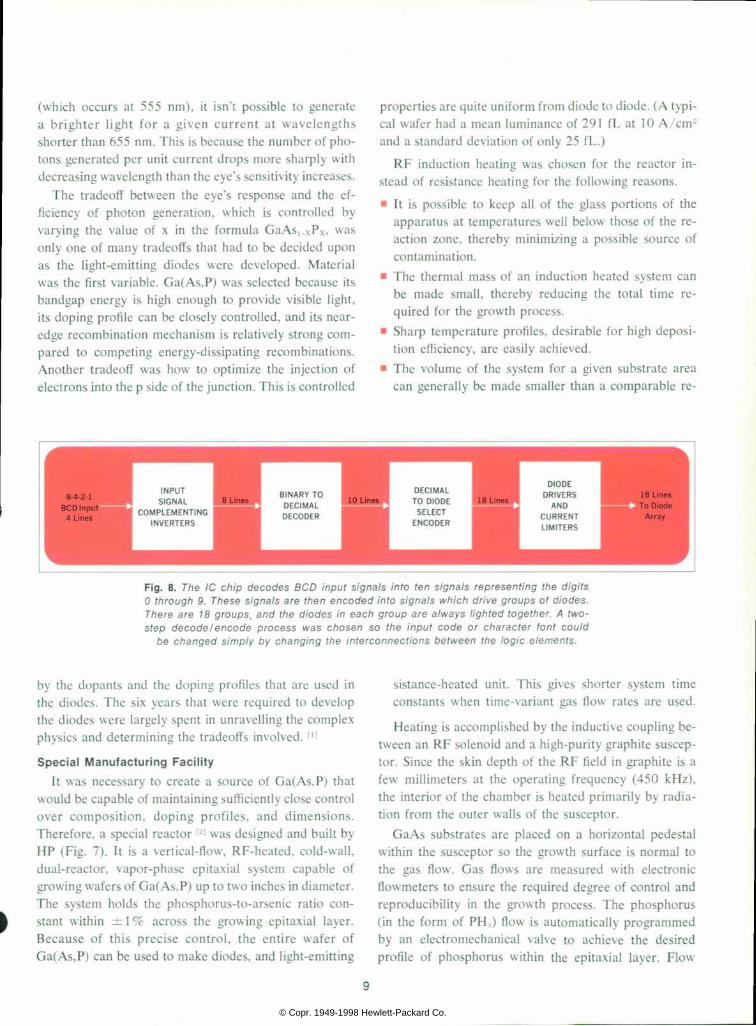
Fig. representing digits 1C chip decodes BCD input signals into ten signals representing the digits 0 t h r o u g h 9 . T h e s e s i g n a l s a r e t h e n e n c o d e d i n t o s i g n a l s w h i c h d r i v e g r o u p s o f d i o d e s . There together . 18 groups, and the d iodes in each group are a /ways l ighted together . A two- s t e p d e c o d e / e n c o d e p r o c e s s w a s c h o s e n s o t h e i n p u t c o d e o r c h a r a c t e r f o n t c o u l d
b e c h a n g e d s i m p l y b y c h a n g i n g t h e i n t e r c o n n e c t i o n s b e t w e e n t h e l o g i c e l e m e n t s .
by the dopants and the doping profiles that are used in the diodes. The six years that were required to develop the diodes were largely spent in unravelling the complex physics and determining the tradeoffs involved. m
Specia l Manufactur ing Faci l i ty It was necessary to create a source of Ga(As.P) that
would be capable of maintaining sufficiently close control over composition, doping profiles, and dimensions. Therefore, a special reactor |L>l was designed and built by HP (Fig. 7). It is a vertical-flow, RF-heated, cold-wall, dual-reactor, vapor-phase epitaxial system capable of growing wafers of Ga(As,P) up to two inches in diameter. The system holds the phosphorus-to-arsenic ratio con stant within ± 1 % across the growing epitaxial layer. Because of this precise control, the entire wafer of Ga(As,P) can be used to make diodes, and light-emitting
sistance-heated unit. This gives shorter system time constants when time-variant gas flow rates are used.
Heating is accomplished by the inductive coupling be tween an RF solenoid and a high-purity graphite suscep- tor. Since the skin depth of the RF field in graphite is a few millimeters at the operating frequency (450 kHz), the interior of the chamber is heated primarily by radia tion from the outer walls of the susceptor.
GaAs substrates are placed on a horizontal pedestal within the susceptor so the growth surface is normal to the gas flow. Gas flows are measured with electronic flowmeters to ensure the required degree of control and reproducibility in the growth process. The phosphorus (in the form of PH3) flow is automatically programmed by an electromechanical valve to achieve the desired profile of phosphorus within the epitaxial layer. Flow
© Copr. 1949-1998 Hewlett-Packard Co.

Measuring Luminance A t H P , d i o d e l u m i n a n c e i s m e a s u r e d b y o p t i
c a l l y i m a g i n g t h e d i o d e ' s l i g h t - e m i t t i n g s u r f a c e
o n a f i b e r - o p t i c p r o b e . T h e f i b e r - o p t i c p r o b e
t r a n s m i t s t h e l i g h t t h r o u g h a f i l t e r . F r o m t h e
f i l t e r t h e l i g h t g o e s t o a p h o t o m u l t i p l i e r t u b e ,
a n d t h e t u b e ' s o u t p u t i s m e a s u r e d b y a d i g i
t a l v o l t m e t e r w h i c h r e a d s d i r e c t l y i n f o o t l a m -
b e r t s . T h e s y s t e m i s c a l i b r a t e d u s i n g a 1 0 0 f L
s t a n d a r d s o u r c e . M a t c h e d p h o t o p i c - f i l t e r / p h o -
t o m u l t i p l i e r - t u b e a s s e m b l i e s a n d c e r t i f i e d
s o u r c e s , t r a c e a b l e t o N . B . S . , a r e p u r c h a s e d
f r o m G a m m a S c i e n t i f i c C o r p o r a t i o n . T h e e l e c
t r i c a l r e s p o n s e o f t h e f i l t e r / p h o t o m u l t i p l i e r
a s s e m b l i e s t o p h o t o n e x c i t a t i o n m a t c h e s t h e
r e s p o n s e o f t h e h u m a n e y e .
F i b e r - O p t i c P r o b e . / W h i s k e r A n o d e C o n t a c t a n d P r o b e
HHt HH1 Iffll fffiTi. H I M I I P W ' ' ' "
M l H M J . 1 H I M I M I l
fH HW Httl WH mrl Hïà l nïà i (No te comb- type anode contac ts o f l i gh t -emi t t ing d iodes )
rates can be changed very quickly, so a wide variety of compositional profiles can be obtained.
Substrate temperature is controlled to ± 1 °C or better by a closed-loop control system whose thermocouple sensing element is located within the substrate pedestal. Temperatures elsewhere in the susceptor are measured by optical pyrometry. The temperature of the arsenic (in the form of AsCl3) reservoir is controlled by a ther moelectric cooling unit.
The initial capacity of the light-emitting-diode pro duction facility is about 1.5 million diodes per year.
The integrated circuits and ceramic substrates for the solid-state numeric indicators are also manufactured by HP. An automatic machine is now being developed to sort and test the diodes and 1C chips, then orient them and attach them to the substrates. Testing is done by a data acquisition and processing system controlled by an HP 2116A Computer.
1C Decode-Encode Logic
Some 400 circuit elements are contained in the 1C chip used in the solid-state numeric indicator modules. Four basic functions are performed in the chip (Fig. 8). Incoming four-line BCD signals are first complemented. Then the eight signals — the four BCD input signals and their four complements — are decoded into ten mutually exclusive line signals, each of which will excite one of the ten decimal digits 0 through 9. Of the sixteen pos
sible binary input codes, the six that don't represent a decimal digit produce blanks. Complementing the BCD inputs was done to minimize the overall complexity of the 1C chip; it greatly simplifies the decoding circuitry.
The third function performed in the 1C is to encode the ten mutually exclusive line signals into signals that select the proper diodes to produce each character. Diodes that are always lighted together are excited by a single output from the 1C chip. The number of diode groups required to produce ten digits is eighteen, so the chip has eighteen outputs. Each of the ten mutually ex clusive line signals activates a subset of the eighteen out puts. These diode drive signals then go through combina tion power amplifiers and current limiters, and excite the light-emitting diodes.
The two-step decode-encode organization was chosen to allow some flexibility in changing the input and output options of the chip. The chip is the electrical equivalent of a ten-position, eighteen-gang switch which has series resistors in all of its outputs and is operated by four BCD signal lines. By simple changes in one of the masks used in making the 1C, either positive or negative BCD inputs can be accommodated, and any 10 of the 21S possible output combinations can be selected. Therefore, changes in character font, presentation of special symbols, or changes in input code can be accomplished quite easily.
Each of the four binary input lines is connected to twenty grounded-collector pnp transistors in the decod-
10
© Copr. 1949-1998 Hewlett-Packard Co.

ing area of the 1C chip. It is connected to the bases of ten of these directly. Between the input and the other ten transistors is an npn emitter follower, which drives an inverter; the input line is connected to the base of the emitter follower, and the inverter output is connected to the bases of the ten pnp transistors. Thus there are eighty pnp transistors in the decoding area of the 1C chip. How ever, not all are operational. Only those needed for the desired decoding function are given emitter connections. The direct-connected pnp transistors that have emitter connections are active when the binary input signal is in the low state (0V). The emitter follower, the inverter, and the remaining pnp transistors that have emitter con nections are active when the binary input signal is in the high state (5V). Emitter connections are made by etching holes in the oxide layer of the chip. When the metal inter connection layer is added, the metal comes in contact with the emitter of a transistor only where there is a hole in the oxide. Thus the chip can be made to respond to either positive logic or negative logic simply by changing the oxide cut mask used in making the 1C.
The same technique allows flexibility in changing the output code of the 1C chip. Each of the ten lines going from the binary-to-decimal decoder into the decimal-to- diode-select encoder is connected to eighteen npn emit ter-follower OR gates. However, not all of the 1 80 npn transistors are connected. Oxide cuts are made for emit ter connections only where connections are needed to turn on one of the eighteen diode drive lines. Any drive line is turned on when one of the ten mutually exclusive decimal lines is turned on and the encoding npn transis tor for the drive line has an emitter connection.
Diode Dr ive Circui t
From the decimal-to-diode-select encoding circuitry, each of the eighteen diode drive lines goes to an npn grounded-emitter inverter which drives a pnp emitter follower. Between the pnp emitter and the output con nection to the light-emitting diode is a current-limiting resistor. The resistor is connected to the n side (cathode) of the light-emitting diode, and the p side (anode) of the diode is connected to the LED-)- terminal of the module. Between this terminal and the ground terminal of the module is the external light-emitting-diode power supply, its positive side connected to the LED-)- terminal. When the diode is forward biased (turned on), about 1.6 volts appear across the diode, and less than one volt appears across the saturated pnp emitter follower. The remainder of the power supply voltage appears across the current- limiting resistor. As the power supply voltage is varied,
Howard C . Borden Howard Bo rden i s manage r o f so l id -s ta te d isp lays a t HP Assoc ia tes . He began h is 28 year career in 1 939 as a mechan i ca l eng inee r . Fo l l ow ing a tour o f du ty w i th the U.S. Navy and fu r the r wo rk as a mechan ica l eng ineer , he dec ided to go in to
T business for himself . He bought an app l i ance s to re , i n t roduced te lev is ion , and saw i t g row to become the la rges t par t o f h i s
bus iness . For the pas t 18 years he has been in research and deve lopmen t i n t he f i e l d o f e lec t ro -op t i ca l -mechan ica l sys tems. He jo ined HP in 1966.
Howard s tud ied mechan i ca l eng inee r i ng a t t he Massachuse t t s I ns t i t u te o f Techno logy and e lec t ron i cs a t the U.S. Navy Rad io Mater ie l Schoo l . In 1961 he rece ived the BA deg ree i n economics f rom S tan fo rd Un ive rs i t y , where he a lso m inored in i ndus t r ia l eng ineer ing . He i s a member o f IEEE, t he Amer i can and Wes te rn Economic Assoc ia t ions , the Op t i ca l Soc ie ty o f Nor the rn Ca l i f o rn ia , and the Soc ie ty fo r In fo rmat ion D isp lay .
Gerald P. Pighini Gerry P igh in i has been in the so l id -s ta te e lec t ron ics f i e ld s ince 1955, when he rece ived h is BS degree in me ta l l u rg i ca l eng inee r i ng f r om B rook l yn Po ly techn ic Ins t i tu te . He has been wi th HP s ince 1965, f i rs t as ch ie f eng inee r o f HP Assoc ia tes and then as p roduc t i on manage r f o r sem iconduc to r s be fo re assuming h i s p resen t respons ib i l i t i es as manager o f
so l id -s ta te d isp lays . Be fore conn ing to HP, Ger ry was ch ie f manu fac tu r i ng eng inee r f o r a p roduce r o f sem iconduc to r dev i ces .
Ger ry i s co -au tho r o f a paper on g row ing l a rge ga l l i um a rsen ide phosph ide wa fe rs f o r l i gh t -em i t t i ng -d iode p roduc t ion . He i s a member o f the Soc ie ty fo r In fo rmat ion Disp lay.
11
© Copr. 1949-1998 Hewlett-Packard Co.

the diode and emitter-follower voltage drops remain nearly constant. The voltage across the resistor, and therefore the diode current, varies nearly linearly with the power supply voltage. This makes the brightness of the diode vary almost linearly with the supply voltage. All of the current-limiting resistors are closely matched (a characteristic of IC's) so the brightnesses of the indi vidual diodes are very nearly equal.
The total time required for a change in input code to travel through the 1C is about 100 ns. The response time of the light-emitting diodes is about 10 ns, so the total response time of the display is typically about 1 10 ns.
The 1C chip is a low-resistivity p* substrate with a p-type epitaxial layer. The output currents flow through the substrate, thereby minimizing the current density in the aluminum interconnecting metal. This construction is a departure from the conventional 1C, which is grown on an n substrate.
Acknowledgments The authors wish to acknowledge the contributions of
people from several HP divisions which have made this
product possible. Developmental work was done in John Atalla's solid-state laboratory, which is part of Hewlett- Packard Laboratories, the corporate research and de velopment facility. Materials work was under Paul Greene and Robert Burmeister, Jr., device work under Robert Archer, and 1C development under John Barrett. Ed Hilton's integrated-circuit department of the Fre quency and Time Division is producing the 1C chips, with James Grace overseeing the transition from the solid-state laboratory. The ceramic substrates are a prod uct of George Bodway's metal-film facility in the Micro wave Division. Light-emitting-diode production, com ponent testing, and final assembly of the pieces is done by the solid-state-display group at HP Associates. S
References [1]. 'Solid state module makes for light reading,' Electronics, September 2, 1968. [2]. R. A. Burmeister, Jr., G. R Pighini, and E E. Greene, 'Large Area Epitaxial Growth of GaAs,.xPx for Display Ap plications,' to be published in Transactions of the A I ME.
© Copr. 1949-1998 Hewlett-Packard Co.

Hybrid Hot Carrier Diodes These un ique comb ina t ions o f p -n ¡unc t ions and Scho t tky bar r ie rs have t he h i gh b reakdown vo l t age and h i gh - t empe ra tu re cha rac te r i s t i c s o f s i l i c o n , t h e l o w t u r n - o n v o l t a g e o f g e r m a n i u m , a n d t h e s p e e d o f S c h o t t k y b a r r i e r d e v i c e s . W h a t ' s m o r e , t h e y c a n b e p r o d u c e d a t l o w c o s t .
By Robert A. Zett ler and A. Michael Cowley
SCHOTTKY BARRIER DIODES, also called hot carrier diodes, have a combination of characteristics that make them hard to beat as switching devices in high-speed computers and as microwave mixers, detectors, and rectifiers. They have the high-frequency characteristics of point contact diodes, but have much higher reverse breakdown voltages. They have uniformity, reproduci- bility, and reliability approaching those of p-n junction diodes, and they have low noise and nearly ideal diode I-V characteristics.
One thing that has been missing, however, is low cost. It has been difficult to make high-reliability Schottky barrier diodes economically. If the devices are passivated to make them easier to produce and to give them high storage temperatures, they have low reverse breakdown voltages — typically 5 to 10 volts. If the devices aren't passivated, they have higher reverse breakdown voltages — 30 volts or more — and are more reliable, but they have maximum storage temperatures of only 125°C and they are harder to produce and therefore more expensive.
The approach taken in our laboratory has been to combine planar p-n junction technology with passivated Schottky barrier techniques to produce a hybrid diode.'1' The first device of this type to reach full production is Model 5082-2800, which has a reverse breakdown volt age greater than 70 volts, 200°C operating and storage temperature, effective minority-carrier lifetime less than 100 picoseconds, and turn-on voltage of only 410 milli volts at 1 mA. It also has low leakage current and will withstand 20,000 g shock. Most important, it can be produced at less than one-fifth the cost of older hot car rier diodes. It is, in fact, comparable in cost to p-n junc tion diodes.
Other hybrid devices are now near production or in
* The p -n j unc t i on gua rd r i ng -Scho t t ky ba r r i e r o r hyb r i d app roach was f i r s t d i sc losed f o r p a t e n t p u r p o s e s b y R . W . S o s h e a o f H e w l e t t - P a c k a r d A s s o c i a t e s i n 1 9 6 5 , a n d w a s l a t e r i n d e p e n d e n t l y c o n c e i v e d b y L e p s e l t e r a n d S z e o f B e l l T e l e p h o n e L a b o r a to r ies ( see re fe rence 2 ) .
development (see page 16). In some, the reverse break down voltages have been lowered to 15 or 20 volts to get higher forward conductance and lower capacitance. In others, parameters have been optimized for power rectification. All of these hybrid diodes are rugged, can withstand high temperature, and have low turn-on volt ages and low cost.
Passivated and Unpassivated Diodes
The Schottky barrier diode is a rectifying metal-semi conductor junction. Any of several metals (gold, molyb denum, titanium, chromium, nickel, nichrome, alumi num, and others) can be used in conjunction with either n-type or p-type silicon. N-type silicon is nearly always preferred because it gives better high-frequency perform ance (electrons, the majority carriers in n-type silicon, have higher mobility than holes, the majority carriers in p-type silicon).
Fig. 1 compares passivated and unpassivated Schottky barrier diodes. The unpassivated diode is made by de positing a matrix of metal dots on a bare silicon surface. Then, by random probing with a metal whisker, contact is made to one of the dots. Reliability is normally high, but the maximum storage temperature is low, and the cost is high because of the random-probing technique.
The passivated Schottky barrier diode is made by first forming a passivating layer of silicon dioxide, SiO.., on the silicon surface, then etching a hole in the passivating layer and depositing a layer of metal over the hole and the surrounding area. One technique for making contact with the metal is to deposit a gold button on the metal, using standard photoresist and plating techniques. Con tact with the gold button is easily made in one try with a metal ribbon. Alternatively, contact can be made directly to the relatively large metal area, using a metal whisker.
In the passivated diode, the layer of SiOL, protects the edge of the diode and improves yield. Standard mass-
13
© Copr. 1949-1998 Hewlett-Packard Co.

F i g . 1 . T w o t y p e s o f S c h o t t k y b a r r i e r d i o d e s t h a t p r e c e d e d t h e n e w h y b r i d t y p e , ( a ) U n p a s s i v a t e d S c h o t t k y b a r r i e r d i o d e i s e x p e n s i v e t o p r o d u c e a n d h a s r e l a t i v e l y l o w m a x i m u m s t o r a g e t e m p e r a t u r e , ( b ) P a s s i v a t e d d i o d e i s l e s s c o s t l y a n d h a s h i g h e r s t o r a g e t e m p e r a t u r e , b u t h a s l o w r e v e r s e - b r e a k d o w n v o l t a g e ( t y p i c a l l y 5 t o 1 0 V ) .
production techniques can be used, and this combined with higher yield brings costs down. However, it has been observed that this type of diode seldom has a reverse breakdown voltage as high as 20 V Usually it is much lower. It is believed that the reason for this lies in the complex interface of the metal, silicon, and SiCX at the edge of the Schottky barrier formed in the hole in the oxide layer. Besides the usual effects of surface states and oxide charge associated with the passivating film, there may be finite-thickness oxide films extending over the semiconductor around the periphery of the hole. Even if there are no oxide films, the interface can be viewed as a degenerate case of a p-n junction which has nearly zero radius of curvature. In this type of junction there would be very high electric fields which would produce avalanche currents at relatively low applied voltages.13"41
Another problem with passivated Schottky barrier diodes on n-type silicon is excess low-frequency noise. This, too, is believed to arise at the edge of the Schottky barrier.
Hybr id Diodes
The new hybrid device, sketched in Fig. 2, is basically a passivated Schottky barrier diode. The essential feature of the device is a diffused guard ring of p-type silicon which extends in planar fashion under the passivating oxide. The Schottky barrier is formed in the interior of the ring and makes electrical contact with the p-n junc tion. The guard ring reduces the edge effects mentioned
above to such an extent that hybrid diodes can have re verse breakdown voltages of several hundred volts. Our first hybrid diode, the HP 5082-2800, has a reverse breakdown voltage of 70 V Similar devices which are optimized for certain receiver applications have reverse breakdown voltages of 15 or 20 V; these are the HP 5082-2811 and the HP 5082-2810.
I -V Characterist ics
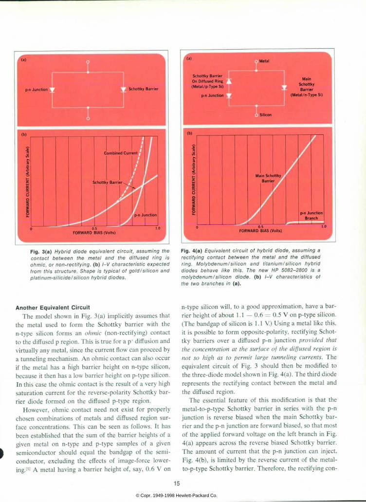
A possible equivalent circuit for the hybrid structure is shown in Fig. 3(a). It consists of two diodes in parallel, one representing the p-n junction and one representing the Schottky barrier. Fig. 3(b) is a sketch of the antici pated forward I-V characteristics of the two diode com ponents alone, and of the total forward I-V character istic. The composite characteristic is dominated by the p-n junction at the higher voltages, where the p-n junc tion injects appreciable minority-carrier charge and hence modulates the conductivity of the n-type silicon layer. If permitted to happen, injection by the p-n junc tion will limit the switching speed at high current levels, because it results in minority-carrier charge storage. At low levels the I-V characteristic is essentially that of the Schottky barrier, so the low-level switching speed will not be limited by storage effects. Nevertheless, a loss of switching speed at high current levels, if allowed to hap pen, would seriously limit the usefulness of the hybrid structure, especially in applications such as computer core drivers and high-frequency modulators. However, it is possible to avoid this loss of speed at high current levels.
F i g . 2 . H y b r i d S c h o t t k y b a r r i e r d i o d e h a s a d i f f u s e d p - n  ¡unc t i on gua rd r i ng unde r t he me ta l and t he pass i va t i ng o x i d e l a y e r . P r o p e r c h o i c e s o f m e t a l a n d d i f f u s i o n p r o f i l e g i v e t h e n e w d i o d e s h i g h r e v e r s e b r e a k d o w n v o l t a g e s , l o w n o i s e , a n d n e a r l y i d e a l I - V c h a r a c t e r i s t i c s .
1 4
© Copr. 1949-1998 Hewlett-Packard Co.
Schottky Barrier On Diffused Ring (Meta l /p -Type Si )
Main Schottk» Barrier
(Meta l /n -Type Si )
F i g . 3 ( a ) H y b r i d d i o d e e q u i v a l e n t c i r c u i t , a s s u m i n g t h e c o n t a c t b e t w e e n t h e m e t a l a n d t h e d i f f u s e d r i n g i s o h m i c , o r n o n - r e c t i f y i n g , ( b ) I - V c h a r a c t e r i s t i c e x p e c t e d f r o m t h i s s t r u c t u r e . S h a p e i s t y p i c a l o f g o l d / s i l i c o n a n d p la t i num-s i l i c i de / s i l i con hyb r i d d iodes .
F i g . 4 ( a ) E q u i v a l e n t c i r c u i t o f h y b r i d d i o d e , a s s u m i n g a r e c t i f y i n g c o n t a c t b e t w e e n t h e m e t a l a n d t h e d i f f u s e d r i n g . M o l y b d e n u m / s i l i c o n a n d t i t a n i u m / s i l i c o n h y b r i d d i o d e s b e h a v e l i k e t h i s . T h e n e w H P 5 0 8 2 - 2 8 0 0 i s a m o l y b d e n u m / s i l i c o n d i o d e , ( b ) I - V c h a r a c t e r i s t i c s o f the two branches in (a ) .
Another Equivalent Circuit The model shown in Fig. 3 (a) implicitly assumes that
the metal used to form the Schottky barrier with the n-type silicon forms an ohmic (non-rectifying) contact to the diffused p region. This is true for a p* diffusion and virtually any metal, since the current flow can proceed by a tunneling mechanism. An ohmic contact can also occur if the metal has a high barrier height on n-type silicon, because it then has a low barrier height on p-type silicon. In this case the ohmic contact is the result of a very high saturation current for the reverse-polarity Schottky bar rier diode formed on the diffused p-type region.
However, ohmic contact need not exist for properly chosen combinations of metals and diffused region sur face concentrations. This can be seen as follows. It has been established that the sum of the barrier heights of a given metal on n-type and p-type samples of a given semiconductor should equal the bandgap of the semi conductor, excluding the effects of image-force lower ing.151 A metal having a barrier height of, say, 0.6 V on
n-type silicon will, to a good approximation, have a bar rier height of about 1.1 — 0.6 = 0.5 V on p-type silicon. (The bandgap of silicon is 1.1 V) Using a metal like this, it is possible to form opposite-polarity, rectifying Schot tky barriers over a diffused p-n junction provided that
the concentration at the surface of the diffused region is
not so high as to permit large tunneling currents. The equivalent circuit of Fig. 3 should then be modified to the three-diode model shown in Fig. 4(a). The third diode represents the rectifying contact between the metal and the diffused region.
The essential feature of this modification is that the metal-to-p-type Schottky barrier in series with the p-n junction is reverse biased when the main Schottky bar rier and the p-n junction are forward biased, so that most of the applied forward voltage on the left branch in Fig. 4(a) appears across the reverse biased Schottky barrier. The amount of current that the p-n junction can inject, Fig. 4(b), is limited by the reverse current of the metal- to-p-type Schottky barrier. Therefore, the rectifying con-
15
© Copr. 1949-1998 Hewlett-Packard Co.

tact to the p region can be used to reduce or eliminate the charge storage under heavy forward bias. This tech nique is responsible for the new hybrid diodes' high switching speed even at high current levels.
Choosing the Metal and Dif fusion Prof i le
It has been our experience that Schottky barrier diodes which have good reverse characteristics are difficult to fabricate on n-type or p-type silicon which has a surface concentration greater than about lO'Ycm1. Therefore, the surface concentration of the diffused ring must be
limited to a value lower than 101S if the equivalent circuit of Fig. 4(a) is to apply. Also, the dependence of the re verse current on the choice of metal must be considered.
The saturation current of a Schottky barrier is given in the emission model by[(i|
Is = AA*T-e kT (I)
where A is the area of the diode, A is the effective Richardson constant (which is approximately the free
Hybrid Technology Produces Many Useful New Devices
H y b r i d h o t - c a r r i e r - d i o d e t e c h n o l o g y h a s m a d e p o s s i b l e a n u m b e r o f n e w s e m i c o n d u c t o r d e v i c e s n o w i n o r n e a r p r o d u c t i o n a t H P . T h e s e d e v i c e s a r e e x p e c t e d t o b e w i d e l y u s e f u l , e i t h e r b e c a u s e t h e y c o s t m u c h l e s s t h a n o l d e r d e v i c e s , o r b e c a u s e t h e y h a v e m u c h i m p r o v e d p e r f o r m a n c e c h a r a c t e r i s t i c s . T h e h y b r i d p r o c e s s p u t s h o t c a r r i e r d i o d e s o n a n e a r l y e q u a l f o o t i n g w i t h p - n j u n c t i o n d i o d e s i n s u c h a r e a s a s r e l i a b i l i t y , r u g g e d n e s s , a n d e c o n o m i c s , a n d t h e h y b r i d d i o d e s h a v e a l l t h e a d v a n t a g e s o f S c h o t t k y b a r r i e r dev i ces as we l l .
High Voltage, High Temperature T h e f i r s t h y b r i d d i o d e t o b e p r o d u c e d i s t h e H P 5 0 8 2 - 2 8 0 0 , w h i c h h a s a r e v e r s e b r e a k d o w n v o l t a g e g r e a t e r t h a n 7 0 V a n d a m a x i m u m o p e r a t i n g a n d s t o r a g e t e m p e r a t u r e o f 200°C. I t s l ow cos t , h i gh - tempera tu re capab i l i t y , r e l i ab i l i t y , a n d r u g g e d c o n t a c t s t r u c t u r e h a v e l e d t o i t s u s e i n h i g h - v o l u m e p r o j e c t i l e f u z e p r o d u c t i o n a n d i n o t h e r a p p l i c a t i o n s r e q u i r i n g s i m i l a r c h a r a c t e r i s t i c s . L o w c o s t a l s o m a k e s i t a p r a c t i c a l r e p l a c e m e n t f o r o r d i n a r y p - n j u n c t i o n d i o d e s i n m a n y R F a n d d i g i t a l a p p l i c a t i o n s i n a w i d e r a n g e o f m i l i t a r y a n d c o m m e r c i a l e q u i p m e n t . I t i s p a r t i c u l a r l y u s e f u l i n d i g i t a l c i r c u i t s w h i c h c a l l f o r l o w f o r w a r d t u r n - o n v o l t a g e o r s u b - n a n o s e c o n d s w i t c h i n g t i m e s . I n f a s t s a m p l i n g g a t e s i t s h i g h r e v e r s e b r e a k d o w n v o l t a g e g i v e s w i d e d y n a m i c r a n g e , i t s l o w t u r n - o n v o l t a g e g i v e s l o w o f f s e t s , a n d i t s n e g l i g i b l e c h a r g e s t o r a g e g i v e s h i g h s a m p l i n g e f f i c i e n c y a n d f u r t h e r f r e e d o m f r o m o f f s e t s .
R e s i s t a n c e t o b u r n o u t , h i g h r e v e r s e b r e a k d o w n v o l t a g e , a n d n e g l i g i b l e c h a r g e s t o r a g e m a k e t h e 5 0 8 2 - 2 8 0 0 a n e f f i c i e n t r e c t i f i e r o r h i g h - l e v e l d e t e c t o r t h r o u g h U H F . I t c a n a l s o b e u s e d a s a w i d e - d y n a m i c - r a n g e U H F m i x e r o r m o d u l a t o r a t h i g h l o c a l - o s c i l l a t o r l e v e l s .
Microwave Mixers and Detectors O t h e r h o t c a r r i e r d i o d e s a r e b e i n g m a d e b y t h e s a m e h y b r i d p r o c e s s t h a t i s u s e d i n t h e 5 0 8 2 - 2 8 0 0 . I n s o m e o f t h e s e d i o d e s , t h e e p i t a x i a l - l a y e r t h i c k n e s s a n d r e s i s t i v i t y , t h e a c t i v e - a r e a s i z e , a n d o t h e r c h a r a c t e r i s t i c s a r e o p t i m i z e d t o p r o d u c e , f o r e x a m p l e , a h i g h e r f o r w a r d c o n d u c t a n c e a n d a l o w e r b a r r i e r c a p a c i t a n c e a t t h e e x p e n s e o f a l o w e r r e v e r s e b r e a k d o w n v o l t a g e . T h i s t r a d e o f f g i v e s t h e d i o d e s o p t i m u m c h a r a c t e r i s t i c s f o r r e c e i v e r a p p l i c a t i o n s a t f r e q u e n c i e s w e l l
i n t o L b a n d . T h e y c a n b e u s e d a s m i x e r s o r d e t e c t o r s , a n d t h e y h a v e t h e s a m e r e s i s t a n c e t o b u r n o u t , r u g g e d n e s s , r e l i a b i l i t y , h i g h o p e r a t i n g t e m p e r a t u r e , a n d l o w c o s t a s t h e h i g h e r - v o l t a g e v e r s i o n . T w o o f t h e s e d i o d e s , t h e H P 5 0 8 2 - 2 8 1 0 a n d t h e H P 5 0 8 2 - 2 8 1 1 , a r e n o w i n t h e e a r l y p h a s e s o f p roduc t i on . O the r t ypes (HP 5082 -2818 and HP 5082 -2819 ) , w h i c h h a v e m i c r o w a v e m i x e r n o i s e - f i g u r e a n d d e t e c t i o n - s e n s i t i v i t y s p e c i f i c a t i o n s , a r e w e l l a l o n g i n d e v e l o p m e n t a n d w i l l b e a n n o u n c e d l a t e r t h i s y e a r .
Rectifiers Under Development H y b r i d h o t - c a r r i e r - d i o d e t e c h n o l o g y c a n a l s o b e a p p l i e d t o t h e p r o b l e m s o f h i g h - f r e q u e n c y p o w e r r e c t i f i c a t i o n , a n d h i g h - c u r r e n t , f a s t - r i s e p u l s e s w i t c h i n g a n d c l a m p i n g . C u r r e n t l y u n d e r d e v e l o p m e n t a r e l a r g e - a r e a h i g h - b r e a k d o w n h y b r i d h o t c a r r i e r c h i p s , p a c k a g e d i n l o w - t h e r m a l - r e s i s t a n c e , h i g h - d i s s i p a t i o n e n c l o s u r e s . T h e y h a v e d e m o n s t r a t e d a n a b i l i t y t o h a n d l e a v e r a g e c u r r e n t s o f 1 0 a m p e r e s o r m o r e a t w o r k i n g i n v e r s e v o l t a g e s o v e r 5 0 v o l t s . T h e i r r e c t i f i c a t i o n e f f i c i e n c y a t o n e a m p e r e p e a k f o r w a r d c u r r e n t i s a s g o o d a t 1 M H z a s t h a t o f m o s t p - n j u n c t i o n ' f a s t - r e c o v e r y ' r e c t i f i e r s i s a t 1 0 k H z , y e t t h e y a r e j u s t a s r u g g e d a s t h e p - n j u n c t i o n d e v i c e s a n d h a v e t h e s a m e s h a r p , c l e a n , r e v e r s e a v a l a n c h e b r e a k d o w n c h a r a c t e r i s t i c s .
E f f i c i e n t r e c t i f i c a t i o n a t h i g h e r f r e q u e n c i e s m e a n s t h a t s w i t c h i n g r e g u l a t o r s a n d d c - t o - d c p o w e r c o n v e r t e r s c a n b e d e s i g n e d w i t h s m a l l e r a n d l i g h t e r f i l t e r c o m p o n e n t s . A n a d d i t i o n a l b e n e f i t o f h y b r i d h o t c a r r i e r p o w e r r e c t i f i e r s i s f r e e d o m f r o m r e v e r s e - r e c o v e r y t r a n s i e n t s p i k e s c a u s e d b y s t o r e d c h a r g e ; s u c h s p i k e s f r e q u e n t l y p r o d u c e s u b s t a n t i a l r a d i o - f r e q u e n c y i n t e r f e r e n c e w h e n p - n j u n c t i o n r e c t i f i e r s are used.
W h e r e l o w - v o l t a g e , h i g h - c u r r e n t d c p o w e r s u p p l i e s a r e n e e d e d , s u c h a s f o r s y s t e m s e m p l o y i n g q u a n t i t i e s o f i n t e g r a t e d c i r c u i t s , a h y b r i d h o t c a r r i e r r e c t i f i e r c a n p r o v i d e a l o w e r f o r w a r d t u r n - o n v o l t a g e ; t h i s i m p r o v e s t h e r e c t i f i c a t i o n e f f i c i e n c y , s i n c e t h e p r i n c i p a l l o s s e s a r e d u e t o t h e f o r w a r d v o l t a g e d r o p o f t h e r e c t i f i e r . A s a r e s u l t , s m a l l e r , m o r e c o m p a c t , m o r e r e l i a b l e p o w e r s u p p l i e s f o r c o m p u t e r a p p l i c a t i o n s s h o u l d b e p o s s i b l e . A n a d d i t i o n a l b e n e f i t i s f r e e d o m f r o m r e v e r s e t r a n s i e n t s , w h i c h e l i m i n a t e s t h e h i g h - l eve l , f as t - r i se no i se sp i kes o f t en gene ra ted by p -n j unc t i on rect i f iers.
15
© Copr. 1949-1998 Hewlett-Packard Co.

electron value for silicon),'7' and <j>BO is the barrier height for zero field. A<£( V) is the image force correction to the barrier height and is given by [8]
(2)
where ND¡A is donor or acceptor density, EK is the semi conductor dielectric constant, and VBo is the diffusion potential of the Schottky barrier (<£BO minus the Fermi energy).
According to (1) and (2), the reverse current of the Schottky barrier depends only weakly on the carrier density or applied voltage (neglecting tunneling) but de pends very strongly on ^>H0. For electron-beam evapo rated molybdenum, <j>,ÃO — 0.42 on p-type silicon; satura tion current /s for a diode of area 10-rj cm- and NA =
5 X 10¹⁷/cm3 would be about 160 /iA. Under the same conditions a gold barrier (0BO — 0.3 V on p-type silicon) can provide a current at 1 V reverse of about 17.5 mA. For platinum suicide, with </>«0 ^ 0.25 on p-type silicon, the saturation current is about 120 mA. Thus, the gold and platinum suicide contacts to the diffused ring, because of their high saturation currents, are essentially ohmic,
while the molybdenum contact is a fairly good rectifier
which limits the current in the p-n junction, thereby pre venting charge storage to a great extent.
We have chosen molybdenum as the metal to be used in the new hybrid diodes.
Character is t ics Agree With Theory
Fig. 5 shows a forward I-V characteristic of a typical molybdenum hybrid diode formed on n-type silicon. The value of 'n' (sometimes called the 'ideality factor') in the
relation
i
was 1.01. This agrees with the value of n calculated from the image force effect.1"1
The reverse characteristics of this diode are shown in Fig. 6. The diode breakdown at 10 /iA is approximately 87 V and sharp. The reverse characteristics are plotted on a semi-logarithmic scale vs (V + VBO — kT/q)1/4 to show that the increase of reverse current with voltage follows the F1/4 dependence expected from image force lowering. The slope of the curve expected from Eqs. (1) and (2) using a dielectric constant of E == 1 1 .7 e0 is 2.52 V1/4/decade. The measured value is 2.47 V1/4/decade.
?'"-
tr. => u
: o o 2 0 0 3 0 0 4 0 0 5 0 0 FORWARD BIAS (mV)
F i g . 5 . F o r w a r d I - V c h a r a c t e r i s t i c o f t y p i c a l M o - S i h y b r i d d i o d e c o n f o r m s c l o s e l y t o t h e o r y .
T h e o r e t i c a l S l o p e = 2 . 5 2 v V D e c a d e Measured S lope = 2 .47 V 'VDecade T = 296°K
F i g . 6 . R eve r se I - V cha r ac te r i s t i c o f t yp i ca l M o - S i hyb r i d d i o d e , s h o w i n g e s s e n t i a l l y e x a c t a g r e e m e n t w i t h i m a g e f o r c e l o w e r i n g t h e o r y .
17
© Copr. 1949-1998 Hewlett-Packard Co.

102 1 0 3 1 0 4 FREQUENCY (Hertz) i
F i g . 7 . N o i s e t e m p e r a t u r e r a t i o f o r t y p i c a l M o - S i h y br id d iode , b iased to to ta l dynamic res is tance o f 1000 Ã ) .
F i g . 8 . A u , M o , a n d T i h y b r i d d i o d e f o r w a r d I - V c h a r a c t e r i s t i c s . D i o d e s w e r e a l l m a d e o n t h e s a m e s i l i c o n w a f e r . A u d i o d e s h o w s v e r y s t r i k i n g l y t h e a d d i t i o n a l c u r r e n t d u e t o h o l e i n j e c t i o n b y t h e p - n  ¡ u n c t i o n . T h i s p - n j u n c t i o n c u r r e n t f o r t h e M o a n d T i d i o d e s i s e s s e n t i a l l y a b s e n t b e c a u s e o f t h e l i m i t i n g e f f e c t o f t h e r e v e r s e b i a s e d r e c t i f y i n g c o n t a c t t o t h e d i f f u s e d r i n g .
Both the forward and the reverse characteristics agree very well with simple Schottky barrier diode theory. There is no need to invoke complex theories involving interfacial films and/or surface states to explain measured deviations from more simple theory. We suggest that in many of the experiments reported in the literature the true Schottky barrier diode electrical characteristics have been obscured by serious edge effects, and that the hy brid structure eliminates these effects.
Noise Suppressed
The noise theory of Schottky barrier diodes has been discussed in another paper. I10i It was shown there that silicon Schottky barriers with space charge fields of the order of 104 V/cm or greater have a noise temperature ratio tn given by
t n = + nls<> + (n — 1)1 '
n l so + J (3)
where IKo is the saturation current of the diode extrap olated to zero applied voltage, n is the 'ideality factor,'191 and / is the forward bias current. The noise temperature ratio of a device biased to a dynamic resistance R is de fined as the ratio of available noise power from the de vice to the available noise power of a resistor R, for the same bandwidth.
For a practical diode consisting of a barrier region and a parasitic series resistance RK, the noise temperature ratio t of the composite structure is
t = R at n -f- RK R R + R S
( 4 )
where Rn is the dynamic resistance of the barrier and RB + RS is the total dynamic resistance of the device, which we denote by R. In a hybrid diode structure, the noise properties of the diode at moderate forward bias levels should be dominated by the Schottky barrier, so (3) and (4) should apply. This has generally been found to be the case, apart from a small amount of excess noise at low frequencies. Some typical data are shown in Fig. 7. The relevant parameters were /so ^¿ 10'9 A,
I ~ 2 .9 X 10 -5 A , n ~ 1 .01 , RK ~ 75 n , and RB
~ 925 n. The resultant ac diode resistance was 1000 n, and the calculated noise temperature ratio was 0.55. The data are in agreement with this value above 30 kHz, while at lower frequencies, there is a small excess noise component which varies approximately as 1/f.
A convenient quantity commonly used to indicate the severity of the excess noise in these diodes is the 'noise
18
© Copr. 1949-1998 Hewlett-Packard Co.
\
corner frequency,' or simply 'noise corner.' We will de note it by fy. It is defined as the frequency at which the excess component of the diode noise is equal to the sum of the thermal and shot noise components. The diode in Fig. 7 has an /v of about 400 Hz. The amount of ex cess noise has been found to vary somewhat from diode to diode; the diode of Fig. 7 was judged to be typical and was selected after examining several dozen diodes from four fabrication runs. Diodes selected for lowest noise have noise corner frequencies well below 100 Hz under the same conditions.
In contrast to the data shown in Fig. 7, it has been observed in our laboratories that passivated Schottky barrier diodes fabricated by simply depositing metal in an oxide window on a silicon wafer have noise corner frequencies ranging from about 50 kHz to over 1 MHz under similar bias conditions. The noise is generally ob served to have 1/f spectrum.
We have concluded from this comparison, and from other data, that the excess noise arises at the periphery of the planar passivated Schottky barrier, and it is ap parent that the p-n junction guard ring has significantly suppressed this excess noise.
Charge Storage Reduced
Hybrid diodes made with three different metals — gold, molybdenum, and titanium — were studied to de termine their charge-storage characteristics. Fig. 8 shows the forward I-V characteristics of the three diodes. It is apparent from the non-constant series resistance that the p-n junction on the gold diode is injecting at some what less than 1 volt, while the diodes with molybdenum and titanium barriers are not injecting heavily even at 1.5 or 2 volts. This difference is to be expected, because the gold barrier on the p-type diffused ring is so low that its saturation current permits the p-n junction to conduct large currents and hence store significant amounts of charge. Molybdenum and titanium, on the other hand, with their much higher barrier heights on the diffused ring, have merely to avoid breakdown below 1 or 2 volts to ensure relatively small amounts of stored charge. The Schottky barriers on the diffused ring are not very close to ideal, since they have the same oxide-interface prob lems as Schottky barriers without the guard ring, but they can typically be made to withstand 2 volts before breakdown, and occasional units will require 5 to 6 volts for breakdown. This is adequate to prevent charge-stor age problems over the normal operating range of the hybrid diodes.
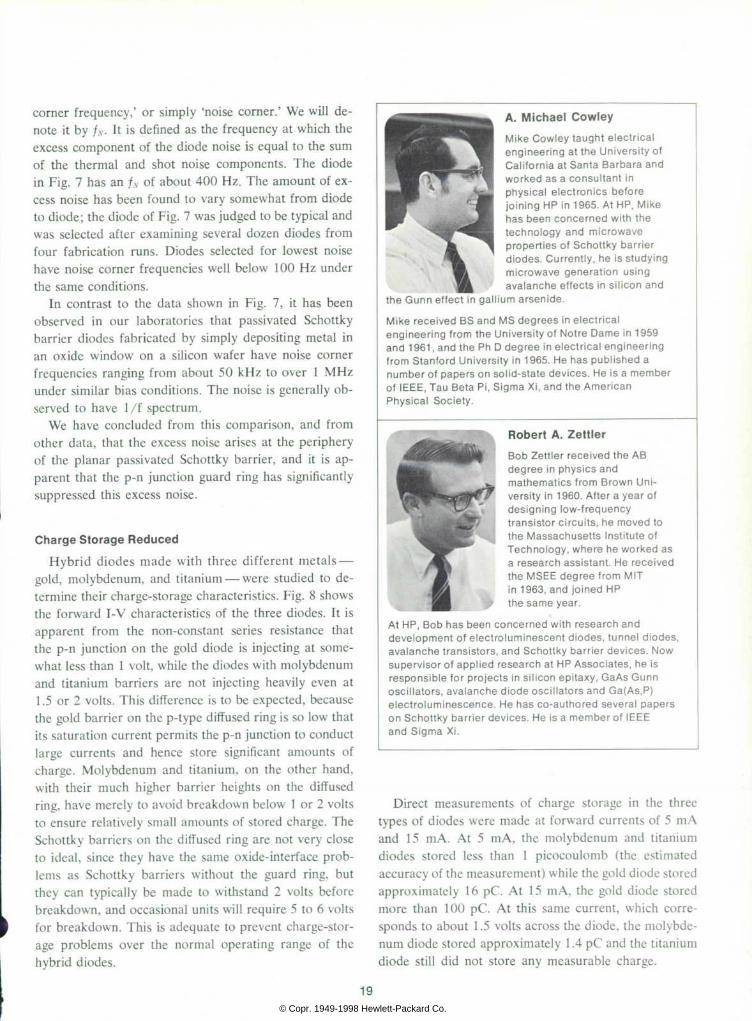
A. M ichae l Cowley Mike Cow ley t augh t e l ec t r i ca l eng ineer ing a t t he Un ive rs i t y o f Ca l i f o rn ia a t San ta Ba rba ra and wo rked as a consu l t an t i n p h y s i c a l e l e c t r o n i c s b e f o r e j o in ing HP in 1965 . A t HP, M ike has been conce rned w i t h t he t e c h n o l o g y a n d m i c r o w a v e p rope r t i es o f Scho t t ky ba r r i e r d iodes . Cur ren t l y , he i s s tudy ing m i c r o w a v e g e n e r a t i o n u s i n g ava lanche e f fec ts i n s i l i con and
the Gunn e f fec t i n ga l l i um a rsen ide .
M ike rece i ved BS and MS deg rees i n e lec t r i ca l eng inee r ing f rom the Un ive rs i t y o f No t re Dame in 1959 and 1961 , and the Ph D degree in e lec t r i ca l eng ineer ing f rom S tan fo rd Un ive rs i t y i n 1965 . He has pub l i shed a number o f papers on so l i d -s ta te dev i ces . He i s a member o f IEEE, Tau Be ta P i , S igma X i , and the Amer ican Phys i ca l Soc i e t y .
A
Robert A. Zet t ler Bob Ze t t l e r r ece i ved the AB deg ree i n phys i cs and m a t h e m a t i c s f r o m B r o w n U n i vers i ty in 1960. A f te r a year o f d e s i g n i n g l o w - f r e q u e n c y t rans is to r c i r cu i t s , he moved to the Massachuse t t s Ins t i t u te o f T e c h n o l o g y , w h e r e h e w o r k e d a s a research ass is tan t . He rece ived t he MSEE deg ree f r om MIT in 1963, and jo ined HP the same year .
A t HP , Bob has been conce rned w i t h r esea rch and deve lopmen t o f e l ec t r o l um inescen t d i odes , t unne l d i odes , ava lanche t rans i s to rs , and Scho t t ky ba r r i e r dev i ces . Now superv i so r o f app l i ed research a t HP Assoc ia tes , he i s respons ib le f o r p ro jec t s i n s i l i con ep i t axy , GaAs Gunn osc i l l a to rs , ava lanche d iode osc i l l a to rs and Ga(As ,P ) e l ec t r o l um inescence . He has co -au tho red seve ra l pape rs on Scho t t ky ba r r i e r dev i ces . He i s a member o f IEEE a n d S i g m a X i .
Direct measurements of charge storage in the three types of diodes were made at forward currents of 5 mA and 15 mA. At 5 mA, the molybdenum and titanium diodes stored less than 1 picocoulomb (the estimated accuracy of the measurement) while the gold diode stored approximately 16 pC. At 15 mA, the gold diode stored more than 100 pC. At this same current, which corre sponds to about 1.5 volts across the diode, the molybde num diode stored approximately 1.4 pC and the titanium diode still did not store any measurable charge.
19 © Copr. 1949-1998 Hewlett-Packard Co.

HP 5082-2800 hybrid diodes, made with molybde num, typically store less than 4 pC at 15 mA and have effective minority-carrier lifetimes less than 100 ps.
Acknowledgments
We wish to thank E. Petherbridge and R. D. Patter son for their assistance in fabricating and characterizing the experimental devices, and C. Forge for the design of our charge-storage test set. We also acknowledge many helpful discussions with R. W. Soshea, J. L. Moll, and M. A . C lark . S
References [1]. R. A. Zettler and A. M. Cowley, 'PN Junction-Schottky Barrier Hybrid Diode,' IEEE Transactions on Electron De vices, Vol. ED- 16, January 1969. (The material in this ar ticle is derived primarily from this reference.) [2], M. P. Lepselter and S. M. Sze, 'Silicon Schottky Barrier Diode with Near-Ideal I-V Characteristics, ' Bell System Technical Journal, Vol. 47, pp. 195-208, February 1968.
[3]. C. Leistiko, Jr., and A. S. Grove, 'Breakdown Voltage of Planar Silicon Junctions,' Solid State Electronics, Vol. 9, pp. 847-852, 1966.
[4]. S. M. Sze and G. Gibbons, 'Effect of Junction Curva ture on Breakdown Voltage in Semiconductors,' Solid State Electronics, Vol. 9, pp. 831-845, 1966. [5]. C. A. Mead and W. G. Spitzer, 'Fermi Level Position at Semiconductor Surfaces,' Physical Review Letters, Vol. 10, pp. 471-472, 1 June 1963.
[6]. H. K. Henisch, Rectifying Semiconductor Contacts, Ox ford University Press, London, 1957, pp. 196-201. [7]. M. M. Atalla, 'Metal-Semiconductor Schottky Barriers, Devices and Applications,' Proceedings of the Microelec tronics Symposium, pp. 123-157, Munich, 1966. [8]. S. M. Sze, et al., 'Photoelectric Determination of the Image Force Dielectric Constant for Hot Electrons,' Journal of Applied Physics, Vol. 35, pp. 2534-2536, August 1964.
[9]. C. R. Crowell and S. M. Sze, 'Current Transport in Metal-Semiconductor Barriers,' Solid State Electronics, Vol. 9, pp. 1035-1048, 1966. [10]. A. M. Cowley and R. A. Zettler, 'Shot Noise in Silicon Schottky Barrier Diodes,' IEEE Transactions on Electron Devices, Vol. ED-15, p. 761, 1968.
HEWLETT-PACKARD JOURNAL e FEBRUARY 1969 volume 20 • Number e T E C H N I C A L C A L I F O R N I A F R O M T H E L A B O R A T O R I E S O F T H E H E W L E T T - P A C K A R D C O M P A N Y P U B L I S H E D A T 1 5 0 1 P A G E M I L L R O A D P A L O A L T O C A L I F O R N I A 9 4 3 0 4
e d i t o r i a l S t a l l : F . J . B U R K H A R D . R . P O O L A N , L . D . S H E R G A L I S , f l . H . S N Y D C R A r t D i r e c t o r : f l . A . E R I C K S O N
© Copr. 1949-1998 Hewlett-Packard Co.