(1942) fm 24-5 signal communication
TRANSCRIPT
8/16/2019 (1942) FM 24-5 Signal Communication
http://slidepdf.com/reader/full/1942-fm-24-5-signal-communication 1/383

8/16/2019 (1942) FM 24-5 Signal Communication
http://slidepdf.com/reader/full/1942-fm-24-5-signal-communication 2/383
FM 24-5
BASIC
FIELD
MANUAL
SIGNAL COMMUNICATION
NOTE-This
is
not
a
revision. This
manual
contains
only
C
1,
31
July
1943, C
2, 30
August 1943,
and C 3,
20 September
1943,
to the
19 October
1942
edition placed
at the back
following
the original
text, and
will not
be
issued
to
individuals
possessing
that edition.
UNITED
STATES
GOVERNMENT
PRINTING
OFFICE
WASHINGTON:
1942
8/16/2019 (1942) FM 24-5 Signal Communication
http://slidepdf.com/reader/full/1942-fm-24-5-signal-communication 3/383
WAR
DEPARTMENT,
WASHINGTON,
October
19,
1942.
FM 24-5,
Basic
Field Manual, Signal Communication,
is
published
for
the
information
and guidance of all
concerned.
[A. G. 062.11 (7-7-42)
.]
BY ORDER
OF
THE
SECRETARY OF
WAR:
G.
C.
MARSHALL,
Chief of Staff.
OFFICIAL:
J. A.
ULIO,
Major
General,
The
Adjutant General.
DISTRIBUTION:
Bn
and H
1-11, 17,
18, 19
(5);
C 11
(10);
IC 1-7,
17,
18,
19
(10);
11
(20).
(For
explanation
of
symbols see FM
21-6.)
II
8/16/2019 (1942) FM 24-5 Signal Communication
http://slidepdf.com/reader/full/1942-fm-24-5-signal-communication 4/383
TABLE OF
CONTENTS
CHAPTER
1. General. Paragraphs
Page
SECTIoN
I.
General_______________________-------
1-4
1
II.
Organization______________________ 5-9 2
III. Command and staff duties of signal
and
communication officers_________
10-12
5
IV.
Disposition
of matériel_______________
-13-16 8
CHAPTEE 2.
Message
center.
SEcrIoN I. General ___________________________-_
17-35
13
II. Procedure for divisions
and higher
units
_____________________________
36-42
31
m.
Procedure
in headquarters
below
di-
vision_____________________________ 43-48 53
IV.
Military
cryptography_________________
49-54 62
V. Cipher device M-94 -______--------
__
55-61
70
VI. Converter M-209
____________-_____-- 62 81
CHAPTER 3. Messenger communication.
SECTioN
I. General
-------------________________ 63-65 83
II. Training of
personnel________________-66-71 84
nm. Employment-_________________________ 72-81 86
IV.
Dropped
messages____________________-82-85
91
V. Pick-up
of
messages__________________
-86-90 94
CHAPTER 4.
Pigeon
communication_--__------------ 91-93 100
CHAPTER 5.
Radio communication.
SECTION I.
General
. .---_______________________ 94-100 109
II.
Tactical
radio nets__a_____ _________ 101-108
115
III.
Operating
regulations__----__-- ______ 109-114
119
IV. Station
records______________________ 115-120 122
CHAPTER 6. Visual communication.
SECTION I.
General_____________________________ 121-122
127
II. Lamps______________________________ 123-130 130
III.
Flags___--- _____-________
__________
131-136
136
IV. Pprotechnics________________________ 137-142
140
V. Panels -------___-- _---_____________ 143-155 144
VI. Airplane maneuvers
as
signals________
156 154
CHAPrTE 7.
Communication
by sound---_____--
___
157-160' 156
CHAPTER 8. Wire communication.
SECTION I. General__---_______________________ 161-182 158
II. Field
wire
line construction _______--
183-208 181
III.
Field telephones and
centrals________- 209-226 239
IV. Field telegraph
sets
and stations___-- 227-233 253
V.
Maintenance of
field
wire
systems...____
234-243
255
CHAPTER
9.
Signal
supply_______________---------
244-254
271
CHAPTER
10. Orders,
records,
and
reports___________ 255-265
278
APP=rinx
I. Wire
communication
equipment --____________ 327
II.
List
of references______________________________ 365
III. International
Morse
Code
_____________________
367
INDEX
--
_________________________________________________
369
M

8/16/2019 (1942) FM 24-5 Signal Communication
http://slidepdf.com/reader/full/1942-fm-24-5-signal-communication 5/383
FM
24-5
BASIC
FIELD
MANUAL
SIGNAL
COMMUNICATION
(This pamphlet
supersedes
FM
24-5,
Basic
Field Manual,
Signal
Communication,
November
1,
1939, including
Training
Circulars
Nos.
3, 28, 53,
and
56,
1941.
and
Training Circular
No. 8,
1942.)
CHAPTER
1
GENERAL
Paragraphs
SmEcroN
I.
General -------------
__
--
---___-_____
_------_
1-4
II.
Organization
-.........................
5-9
III.
Command
and
staff duties
of
signal and commu-
nication
officers
----------------.............
10-12
IV.
Disposition
of
matériel-
-----
_--------------___
13-16
SECTION
I
GENERAL
U 1. FNcTioNs.-Signal
communication
enables
a com-
mander
to
send
and
receive
information and
orders.
*
2. OBJECT.-The
object of
this manual
is
to
furnish
basic
information
governing
signal communication
essential
to
officers
and
enlisted
men
of all arms
engaged
in
communi-
cation
activities.
U
3.
ScoPE.-The
scope of
this
manual
includes
the
methods
and
technique
relating
to the
installation,
operation,
main-
tenance
of,
and planning
for
signal
communication with
spe-
cial emphasis
on such
systems
employed
within
the
division
and smaller
units.
*
4.
REFERENCES.-a.
Training
publications.-For
a
complete
list
of
War
Department
training
publications,
see FM
21-6.
See appendix
II
for
a reference
list
for
Signal
Corps
equip-
ment and
activities.

8/16/2019 (1942) FM 24-5 Signal Communication
http://slidepdf.com/reader/full/1942-fm-24-5-signal-communication 6/383
4-5
BASIC
FIELD
MANUAL
b. Miscellaneous.-(l)
Army
Regulations.-Instructions
e-
lating
to signal communication
and Signal Corps
activities
are
found
in
the
AR
105-series.
(2) Tables of Organization.-Tables
of Organization
pre-
scribe
the organization of signal
and communication
units
and
personnel
and
show
the authorized
items of
transporta-
tion and weapons.
(3) Tables
of
Basic Allowances.-Tables
of
Basic Allowances
list items
of signal
equipment
authorized
for signal
or
com-
munication
units
with the basis
of issue.
(4) Signal
Corps General Catalog.-The Signal Corps Gen-
eral Catalog
includes a
descriptive
section, a stock section, and
several appendixes.
This
catalog is
essential to all signal
property and supply
officers.
(5) Circulars
issued
by the
Chief Signal Offlcer.
SECTION II
ORGANIZATION
* 5. DEFINITIONS.---.
Message.-The term
"message"
as used
herein
includes all instructions,
reports, orders,
documents,
photographs, maps,
or other
intelligence, in
plain language
or code, transmitted
by a
means of
signal communication
(see
c below).
b.
Agency
of
signal
communication.-The
term
"agency
of
signal
communication"
embraces
the personnel and
equip-
ment necessary to
operate message centers,
signal intelli-
gence, signal supply, signal
repair,
and messenger,
pigeon,
radio,
visual, sound,
and
wire
communication.
c. Means of signal
communication.-A
"means
of signal
communication"
is
an
agency
of signal
communication
capable
of
transmitting
messages.
The
following agencies
are
means
of signal communication:
messenger,
pigeon,
radio,
visual,
sound,
and
wire.
d. Command
post.-The
command post is
the
location
of
the forward
echelon of a headquarters
during
combat from
which tactical
control
is
normally
exercised
and to
which
tactical
information
from
subordinate
units
is
sent.
When
the commander
leaves his command
post
for any
purpose,
2
8/16/2019 (1942) FM 24-5 Signal Communication
http://slidepdf.com/reader/full/1942-fm-24-5-signal-communication 7/383
SIGNAL
COMMUNICATION 5-8
he maintains
constant
communication
with it through the
speediest
and most reliable means of signal communication
available to
him.
Only
by
such
means
can
his
effectiveness
as a
tactical commander
be
constantly maintained.
e. Axis
of signal communication.-To
secure continuity of
command
and
signal communication
in
combat
when the
movement
of command
posts
either forward or
backward
is
contemplated, the
probable successive command posts
should be selected in
advance.
The
"axis of signal com-
munication" is
designated
by
naming these probable suc-
cessive
locations
in
the
direction
of
movement.
These
points
may
not
actually
be occupied by the command
post,
but the
command post will move along
the
route indicated by
the
points
named.
*
6.
SIGNAL
AND
COMMVUNICATION UNITS.-Specially
trained
personnel and technical equipment required for the operation
of signal communication are provided by Tables of Organiza-
tion
and
Tables
of
Basic
Allowances
for
signal
communica-
tion units to serve each battalion and higher headquarters.
Signal Corps
units
are herein
referred
to as
signal
troops,
and
others as communication troops.
E 7.
SIGNAL
SYSTEMs.-The signal
system
of each tactical
unit is complete
within itself
and
embraces
the signal sys-
tems of
subordinate
units
to meet
the
need
of
the
unit com-
mander.
It
also
forms
an
integral
part
of
the
system
of
the
next
superior unit. All systems combine
to
form one
coor-
dinated
system.
I
8. SIGNAL
AGENCIES
AND MEANS.---a. Agencies.-The
follow-
ing agencies of signal communication
may be
employed
in the
signal
systems
within the division and higher
units:
(1) Message centers.
(2) Messenger communication.
(a) Airplane
messenger.
(b) Motor messenger.
(c) Motorcycle
messenger.
(d)
Bicycle
messenger.
(e)
Mounted
(horse) messenger.
(f) Runner (foot
messenger).
(3) Pigeon
communication.
3

8/16/2019 (1942) FM 24-5 Signal Communication
http://slidepdf.com/reader/full/1942-fm-24-5-signal-communication 8/383
8-9 BASIC FIELD
MANUAL
(4) Radio communication.
(a) Radiotelegraph.
(b) Radiotelephone.
(5)
Visual
communication.
(a) Lamps.
(b) Flags.
(c) Panels.
(d) Pyrotechnics.
(e) Airplanes.
(6) Sound
communication.
(7)
Wire communication.
(a) Telephone.
(b) Telegraph.
(c) Teletypewriter.
(8) Signal supply.
(9) Signal repair.
b. Means.-The
signal
systems within
the division generally
employ
the
following
means:
radio,
wire,
messenger, sound,
and visual.
Pigeon,
and certain forms of
visual and sound
communication,
are
used for special purposes.
Choice of the
means
employed in each instance
depends on
the situation.
Exclusive'
reliance upon any one
means is unwise because
special
and
unforeseen
circumstances may
render that means
inoperative
when most needed.
Plans of all commanders
will
make
advance
provision for
prompt
employment of effective
and
reliable
alternate
means; and
the
simultaneous operation
of
several
means will minimize
the ill effects
of
complete
in-
terruption
in
any one. In general,
the primary means actually
used for tactical purposes
will
be that
which
combines
the
greatest
facility
and
speed
of
installation
and
operation
with
the
required secrecy and
dependability.
* 9.
TrEAwoRK.-To
insure successful signal
communication,
the
signal and
communication
troops
must
work as
a
team
regardless
of
unit,
arm, or
service. There
must
exist a spirit
of
mutual helpfulness
and cooperation. Signal
communica-
tion
personnel
at
any
headquarters
should become
personally
acquainted with
personnel
at other headquarters
with whom
they communicate
directly. This includes
units
in
all rela-
tionships
(supported, supporting,
superior, subordinate,
ad-
4

8/16/2019 (1942) FM 24-5 Signal Communication
http://slidepdf.com/reader/full/1942-fm-24-5-signal-communication 9/383
SIGNAL
COMMUNICATION
9-10
jacent,
and
attached)
and
is regardless of the
point at
which
the
responsibility
for
communication
is fixed.
Personal
con-
tact
promotes
a
better
understanding
of
the
special
problems
and
conditions which
exist
at
each
headquarters
and permits
full assistance
and cooperation
in
the installation,
operation,
and
maintenance
of
signal
communication.
SECTION m
COMMAND AND
STAFF DUTIES OF
SIGNAL
AND
COMMUNICATION
OFFICERS
U 10. RESPONSIBILITY.-a.
Commander.-Responsibility
for
signal
communication
is
a function
of command
and
is pre-
scribed
in AR
105-15.
In
general,
the
tactical commander
is
responsible
for the
installation,
operation,
and
maintenance
of
all
agencies of
signal communication
which
form
the signal
system for
his unit, and for
the efflcient functioning
and
coordination
of
signal
communication
in
subordinate
units.
To
that end
he prescribes the
requisite training of personnel
in
all echelons
under
his
command and
the
application
of
such
training
in field operations
in the same
manner
and to
the
same extent
as
for
other tactical
functions
and
means.
Mobilization
Training
Programs
for each
type
of unit are
issued
by the
War Department.
b. Signal or
communication
oyfcer.-In
general,
each
tacti-
cal
unit
commander
down
to
the battalion
is
provided
with
a
special
staff officer
trained in the tactics
and
technique
of
signal communication.
He is charged,
under
the direction
of
the unit commander
(or his
G-3
or S-3),
with
the exercise
of
tactical
supervision
of signal
communication
for the entire
command,
and
with initiating,
through
proper recommenda-
tions,
the
necessary
measures
for
the training
of personnel
or
subordinate
units
in
signal
communication
for combat.
Por
ground
units
in
the
division
and higher
headquarters
and
for
air units
in the
wing and
higher headquarters,
this special
staff
officer
is known
as
the
signal officer;
in units
below
the
division and wing
he
is known as
the communication
officer.
c. Channels
of
supervision.-All
orders affecting
the tacti-
cal
employment
of
signal
communication
are issued
through
5

8/16/2019 (1942) FM 24-5 Signal Communication
http://slidepdf.com/reader/full/1942-fm-24-5-signal-communication 10/383
10-12
BASIC
FIELD
MANUAL
the
normal channels
of
command
and
are
coordinated
with
orders
issued to other
tactical or technical
agencies by the
appropriate
staff
section
prior to
their
issue.
Orders
per-
taining to routine matters issued for the technical
control
of
an
agency
of
signal
communication
and which
do
not
need
coordination
with orders
issued to
other elements
of the
command
may
be
issued in the
name
of the
commander
by
the
communication or signal
officer
of
the superior
unit to
the communication
or
signal officer
of the
subordinate
unit.
* 11. STAFF
AND
COMMAND
FtNcTIoNS.--a.
The signal
or com-
munication
officer,
as a member
of
the special staff
group,
assists the
tactical
commander in
exercising his
command
functions
relative
to signal communication
and acts
as
an
adviser
to the
commander
and other
members
of the
staff on
all
matters
relating
to signal communication.
Under
in-
structions received from his
commander, he
acts as
inspector
and coordinator
of
the training
and operations
of subordinate
signal
or
communication units.
b. The
signal officer
commands,
so
far
as
relates
to
training
and
tactical
employment,
all
signal
troops assigned
to
serve
his
headquarters.
As a
commander
of troops,
the signal
officer
is responsible for the
proper training
and tactical
employment of
his own
signal
units.
c.
These
two functions
of staff
and
command,
although
vested in the same individual,
are separate and
distinct
in
that
each
involves
different responsibilities
and
duties
and
the
exercise
of
one
should
not
be confused or permitted
to
inter-
fere
with
the exercise
of the
other.
However,
this dual
func-
tion of the signal
officer
has many advantages
in
facilitating
the
proper
discharge
of
both his
command
and
staff duties.
E
12.
DETAILED DTIES.--a. Signal
offcer.-(1)
During mo-
bilization.-During mobilization
the
signal
officer-
(a)
Prepares
requisitions for personnel
to
bring his
unit
to
authorized
strength.
(b) Inventories
and
inspects signal
equipment,
and requi-
sitions what
is needed
to bring the
quantity
on hand up to
that
authorized by Tables of
Basic
Allowances
for
his unit
and
for
subordinate units.
6

8/16/2019 (1942) FM 24-5 Signal Communication
http://slidepdf.com/reader/full/1942-fm-24-5-signal-communication 11/383
SIGNAL
COMMUNICATION
12
(e) Prepares
the
training
programs for
signal communi-
cation
troops
of
his
unit
under the
general
policy laid
down
by his
commander
and
by
higher
authority,
adapting
the
policy
to meet local
conditions
and
the
time
period
allowed
for
mobilization.
(d) Takes
steps
to
secure
and
supply
authorized
training
equipment
throughout
the
command.
(e)
Organizes
and supervises
such troop
schools
for com-
munication
specialists
as may
be authorized
by
his com-
mander
or required
by
orders of
higher authority.
(f)
Prepares
for
the
approval
of
the
commander such
rou-
tine orders
and signal
operation
instructions
as
may be
needed
for the
efficient
training
of
the signal
and communi-
cation
personnel
of the command.
(g)
Personally supervises
the training
of the signal
troops
assigned to
serve his headquarters,
and
obtains their
train-
ing
and
organization
equipment.
(h)
Recommends
training
for
the
signal
and
communica-
tion
units
with the
staffs and
the
troops
throughout
the
command.
(2)
During
actual or
simulatecl
combat.-During
actual
or
simulated
combat
the signal
officer-
(a)
Prepares
or secures from
higher
authority
such orders
and signal operation
instructions
as may
be
needed
to
insure
tactical
and technical
control
of the signal
systems
of the
command.
Insures
the
proper distribution
of
such
orders
and signal
operation
instructions
throughout
the
command.
(b)
Recommends
the initial location
of the command
post
of
the
unit
which
he serves,
if
this
location
has
not been
prescribed
by higher
authority.
Recommends
the
initial
locations
for the
command
posts of
the
next
subordinate
units when
practicable.
When
the
necessity
for
the dis-
placement
of
command
posts
during
the
operation can
be
foreseen, recommends
the
axes of
signal communication
for
the
next
subordinate
units and
for the unit
which
he serves
when
it has
not been
prescribed
by
higher authority.
Sub-
mits these recommendations
to the commander
or
his
desig-
nated staff
officer.
(c)
Prepares
plans
for the
employment
of
the
signal
agen-
cies
of
the
unit which
he serves and
for subordinate
units
so
7
8/16/2019 (1942) FM 24-5 Signal Communication
http://slidepdf.com/reader/full/1942-fm-24-5-signal-communication 12/383
12-13
BASIC
FIELD
MANUAL
as to insure the most
efflcient
employment of these
agencies
within
the headquarters of the
unit
which he serves
and the
necessary
coordination and
technical
control
of
the
agencies
of
subordinate
units, subject
to
orders
received
from
higher
authority.
Submits these
plans
to
his
commander
or to the
appropriate
staff
officer for
approval.
(d)
Prepares
all
signal
orders based
upon
the
approved
plan of
signal
communication,
transmits
these orders
to
the
proper
issuing
agency,
checks on the
issue of
these orders,
and supervises
their execution.
(e)
Establishes
and
operates
the
signal
communication
system
for
which his
unit commander
is directly
responsible;
makes
technical
inspections of the signal
communication
personnel
and
equipment
throughout
the
command
as his
commander
may direct,
and
submits recommendations
to
his commander concerning
the action
that
should be taken
to
correct
the deficiencies
that
may exist,
or to
improve
the
training
methods
or
doctrine.
(f)
Supervises
the
replacement
of signal
equipment
and
personnel
of
the
unit
which he serves
and of subordinate
units.
b. Communication
officer.-The
communication
officer
performs duties
similar
to
those for a signal
offlicer with
re-
spect
to
the
signal communication
troops of the
unit
which
he serves
and
subordinate
units
when such duties
are appro-
priate.
SECTION
IV
DISPOSITION
OF 1MATÉRIEL
* 13. GENERAL.-When
signal communication
equipment
is
in
imminent danger of
capture by the enemy,
it must be
destroyed in accordance with
the
following:
a. Unclassified
and
restricted
communication
equipment.-
This
equipment
will be
destroyed
beyond
possibility
of
repair
or
reclamation
of
parts.
b. Secret
and
confidential
communication
equipment,
codes,
ciphers,
cipher
devices
and all
instruction
books.-
These
will be
destroyed
beyond
recognition.
Only those
parts
of
a
secret
or confidential
device which
show secret
principles
8

8/16/2019 (1942) FM 24-5 Signal Communication
http://slidepdf.com/reader/full/1942-fm-24-5-signal-communication 13/383
SIGNAL
COMMUNICATION
13-14
or
design must
be destroyed beyond recognition.
Other
components
not involving secret or
confidential
principles,
such
as power supplies,
cabling,
etc.,
need
be
destroyed
only
to an extent
that
would
prevent
future
use or
reclamation.
Personnel who
are responsible
for
secret
or confidential
equipment must
be familiar with any special or detailed
ia-
structions relating to any particular
device
and
must
be
prepared
at
all times to
carry out
these instructions without
delay.
In
those cases
where special instructions have
been
issued regarding
certain
devices,
personnel responsible
will
be
prepared
and
equipped to carry them out without delay.
E 14.
DESTRUCTION.-a.
Priority.-In destroying parts of
equipment
which
are to
be destroyed only
to an
extent suffi-
cient to prevent their future use or reclamation, the following
priorities
will be followed:
(1)
Parts
which are nonstandard
and
unusual,
either from
a mechanical
or electrical
standpoint, since
the likelihood
that
the
enemy
can replace
them
would
be
small,
particularly
if
all captured
units
of a particular
item have
the
same
non-
standard
component
destroyed.
(2) Critical
units,
since
the
likelihood
that the
enemy
would
be able to replace them would be smaller
than for
non-
critical items.
(3) Parts
interchangeable
with
other equipment, to
prevent
the
enemy
from
using
them
to
salvage
other
types
of
destroyed
equipment.
(4) Other
parts.
b. Methods.-The
following general
means
of
destruction,
utilizing the usually available tools and materials, are pre-
scribed for the
principal
items of signal communicátion
equipment:
(1)
Books
and
papers.-Instruction
books,
circuit and
wir-
ing
diagrams,
records of all
kinds
for
all types
of Signal
Corps
equipment, and
code books and registered
documents
should
be
destroyed by
burning.
Each
cryptographic
security
officer
will
secure
a 5-gallon can of gasoline to be kept within
easy
reach and
close
proximity
to the
storage place
of
all
registered
documents. If
possible, each document
will
be
separated
into
individual sheets, each sheet crumpled, and all placed in a
9

8/16/2019 (1942) FM 24-5 Signal Communication
http://slidepdf.com/reader/full/1942-fm-24-5-signal-communication 14/383
14
BASIC
FIELD
MANUAL
pile.
The
pile may then
be
saturated
with
gasoline
and
ignited;
for
safety,
a lighted match
may be thrown from
a
distance
of
at
least
6
feet.
(2) Engines.-All gasoline
engines, whether a
part
of
a
truck or
an engine
generator, should be
demolished in
order
of importance
of
the principal parts such
as engine block,
magneto, carburetor,
radiator, cylinder
heads, manifold, and
fuel
tanks.
(3) Generators.-All
generators
should
be demolished
in
order
of
importance
of
the
principal
parts,
which
are casting,
armature
windings, commutator,
brushes, and main
casting.
The armature
windings,
and in
some instances the
field
windings, of generators
may
be destroyed
by
short-circuiting
prior
to demolition of the prime
mover.
(4) Power switchboards.-The principal
power switch-
board parts
to
be demolished in order
of
importance are
meters,
regulators
or relays,
switches, and
wiring. These
parts
may
be
destroyed
by sledges
and
axes.
(5) Telephone switchboards.-Switchboards
should
be
destroyed
with
any hammer,
ax, sledge, or other
means
of
demolition available.
Destruction
should be accomplished
in the following
order: Jacks, keys,
relays, battery
and
meter
protective
units, head and
chest sets, and power
equipment.
(6)
Radio sets.-Destruction of equipment
by explosives,
when
provided,
is
prescribed
in appropriate instructions.
All
radio
sets may be
destroyed in the following
manner:
(a)
Shear
off
all
panel knobs, dials, etc.,
with an ax
head.
Break open
set compartment
by
smashing in
panel
face, then
knock off top,
bottom,
and sides.
The
object is to destroy
the
panel
and
expose the
chassis. On the
top
of
the chassis,
strile
all tubes and
circuit elements
with
the
ax head.
On
the under
side
of
the
chassis the ax
head should
be
used for
shearing
and tearing
off
wires
and
small
circuit
units.
Sock-
et bases
should be broken and circuit
units and
wires cut.
Tubes, coils,
crystals and
holders,
microphones, earphones,
and
batteries should
be smashed
or
cut, the
treatment
and
tool being
the same
as
for
chassis
parts.
Masts
and
poles
should be
broken
at the joints by bending.
The variable
gang
tuning condenser
is
the
most
difficult
part to replace
and should
therefore
be
destroyed.
10

8/16/2019 (1942) FM 24-5 Signal Communication
http://slidepdf.com/reader/full/1942-fm-24-5-signal-communication 15/383
SIGNAL
COMMUNICATION
14-15
(b)
The
following
supplementary
means
of
destruction
should
be
employed
whenever
possible:
1.
Pile
up
equipment already
smashed as outlined
above, and
pour on
gasoline
or
oil and
set
on fire.
If
other
inflammable
material
such
as
wood,
saw-
dust, cloth,
straw,
etc.,
is
available,
pile up
this
material
and
place
equipment
on
it
before
pouring
on
gasoline
or
oil.
2.
Smashed parts
should be buried
in
earth or
stream
beds.
(7) Radio
stations.-Destruction
of
radio
stations
may
be
accomplished
in
the
same manner
as described
for radio
sets
except that
additional demolition
is
required for
all
perma-
nent
fixtures such
as antennae
towers
and
power plants.
Such
permanent
and heavy
fixtures
may be
destroyed
by
explosives
and
in
the case
of
engines,
generators, and
power
switchboards by
the methods
covered
in
b,
c,
and
d
above.
(8) Telegraph
equipment.-Telegraph
switchboards,
sets,
and
printers
should
be
destroyed
in
the
same
manner
as
tele-
phone equipment.
It
is particularly
important
to smash
gears
and frame
castings
of
teletypewriters.
(9)
Meteorological
equipment.-All
meteorological
equip-
ment
such
as
barometers,
anemometers, wind
vanes,
ther-
mometers,
hydrometers,
wind-indicating
instruments,
rain
gages,
sunshine
gages,
recorders,
and meteorographs
may
be
destroyed
by
means
of
bending or
crushing with
heavy
instruments.
(10)
Visual
signaling equipment.-All visual
signal
equip-
ment
may be
rendered
permanently
inoperative
by destroying
all
glass,
particularly
optical
glass,
metal
reflectors,
gears,
and
wiring
by
bending
or smashing
with
heavy instruments.
(11) Miscellaneous.-Transmitters
and
receiver
units of
telephones
and head and
chest
sets
should be
destroyed by
hammering. Items containing
rubber,
such
as
rubber-tired
reel carts,
wiring
of all types,
and
field wire
should
be
de-
stroyed
by cutting
and
burning.
*
15. CAPTURED
EQUIPMENT.-In order
that captured
enemy
signal
communication
equipment
may
be
reused by
friendly
troops,
turned
in for
salvage
of usable
parts, or
studied to
11
8/16/2019 (1942) FM 24-5 Signal Communication
http://slidepdf.com/reader/full/1942-fm-24-5-signal-communication 16/383
15-16
BASIC
FIELD
MANUAL
gain
information
about
the
enemy,
it
must
be
handled
promptly
and
placed
in
the
proper
channels.
In
order
to
study
such
equipment an
identification
officer
is
provided
at
infantry
division
and
similar
or
higher
unit
headquarters
in
the
theater
of
operations.
Al
personnel
should
imme-
diately
report
captured
enemy
signal
communication
or
cryptographic
equipment
to
the
nearest
signal
or
communi-
cation
offlcer.
Where
circumstances
permit,
installed
equip-
ment
will
not
be
disturbed
before
the
arrival
of
specially
trained
personnel.
For
further
details
see
FM
11-35.
Caution:
Such
equipment
may
conceal
"booby
traps"
which
will
cause
casualties
to
unwary
personnel.
*
16.
RESPONSIBILTY
OF
SIGNAL
OFFICERS.-Signal
officers
will
be
familiar
with
all
items
of
equipment
for
which
they
are
responsible,
in
order
that
they
may
prescribe
other
means
of destruction
as necessary
to
meet
unusual
conditions
in
the
field.
Such
instructions
will
be
coordinated
by
the
senior
signal
officer,
and
copies
forwarded
to
the
Chief
Signal
Officer.
12
8/16/2019 (1942) FM 24-5 Signal Communication
http://slidepdf.com/reader/full/1942-fm-24-5-signal-communication 17/383
CHAPTER
2
MESSAGE
CENTER
Paragraphs
SECroN I.
General
-....................................
__
17-35
II.
Procedure
for divisions
and
higher units
.------
6-42
III.
Procedure
in headquarters
below
division
-------
43-48
IV.
Military
cryptography
---
.
-------------------
49-54
V.
Cipher device
M-94
-____________-____________
5-61
VI.
Converter
M-209
-----------
___------_---------
62
SECTION
I
GENERAL
*
17. DEFINITIONS.-a.
Message
center.-The
message
center
is the
agency
of
the
commander
at
each
headquarters
or
command
post charged
with the
receipt,
transmission,
and
delivery
of
all messages
except those
indicated
in
paragraphs
20d and 48b(3).
b.
Addressee.-An
addressee
is
the
person
or
office
to
which
a
message
is to be
delivered.
The
term
includes
a
representative
authorized
by
an
addressee
to receive
his
messages.
Addressees
may be
indicated
as
"action"
or
"in-
formation",
depending
upon
the
purpose for
which
the
mes-
sage
is
sent
to
them.
c.
Message.-See
paragraph 5a.
d.
Writer.-The
originator
of
a
message
is
called
the
writer.
e.
Cryptography.-See
paragraph
50.
*
18.
PURPOSE.--a.
The
purpose
of the
message
center
is
to
speed
the
transmission
of authentic
messages
by-
(1)
Providing
a designated
point
to which
messages
and
messengers
may
be
directed.
(2) Keeping
informed
of
the current
effectiveness
of
each
available
means
of
signal
communication.
556773*-43--
13
8/16/2019 (1942) FM 24-5 Signal Communication
http://slidepdf.com/reader/full/1942-fm-24-5-signal-communication 18/383
18-19 BASIC FIELD
MANUAL
(3)
Properly
distributing
message traffic to
the
available
effective means of signal communication.
(4)
Eliminating
unnecessary
delays
in
transmission.
(5) Operating an efficient messenger service.
b. Message centers of
divisions
and higher units are
oper-
ated by Signal
Corps
units. Message centers of units below
the
division are
operated
by
communication
personnel of
those units. Message
centers are located
at the
command
post and at the
rear
echelon
of
the headquarters.
Advance
message centers for the reception and relay of messages
are
employed as a
part
of
the
signal system
to
facilitate
signal
communication with
advanced units
or
units operating on
a
flank.
c.
Advance
message centers are established when required
to
relay messages
transmitted
by
different means
of signal
communication or through
different
channels of the same
means.
Information
of their locations
will be
transmitted
to interested
unit
signal
or communication
officers,
who
are
responsible
for
the
proper
and
rapid
dissemination
of this
information. Advance message centers often are employed
as
a part of
the
signal
system to
facilitate the
transmission
of
information and reports
from front line
reconnaissance
and
security
units, and as collecting points for messages from
several
reconnaissance
detachments in the
reconnaissance
operations of
cavalry divisions. A staff offlcer
may be
as-
signed
to
the
advance
message
center
to
receive,
evaluate,
and
consolidate
messages for retransmission
to the
rear.
d.
The
message center
is
not organized or equipped
to
per-
form
stenographic
or
clerical
work pertaining to the head-
quarters which it
serves. It
is not
equipped
to prepare
copies
of outgoing
messages
for
multiple
transmission, nor
to
prepare
additional copies of incoming
messages
for
multiple
distribu-
tion.
It will therefore not
be
used for these purposes.
(See
pars.
25
and
37h.)
O 19. CLASSIFICATION
OF
MESSAGES.-Messages are classified
according
to-
a.
Secrecy.-Messages
are classified as secret by the writer
if their content
so
warrants.
In simulated
or actual
tactical
operations, all messages not classified
as
secret will be
re-
14
8/16/2019 (1942) FM 24-5 Signal Communication
http://slidepdf.com/reader/full/1942-fm-24-5-signal-communication 19/383
SIGNAL COMMUNICATION 19
garded
as confidential and need not be so marked. (See AR
380-5.)
b.
IntelZligibility.-This
classification
refers
to
whether
the
message is
in clear or cryptographed
(sec. IV).
(1) A
clear
message
is one
in which the text of
the message
conveys an intelligible meaning in a spoken language.
(2) A
cryptographed message is
one in
which the text
of
the
message
conveys
no
intelligible meaning in any
spoken
language.
e. Precedence
with
which
handled.-Messages
may
be
clas-
sified as
urgent, operational priority, priority,
or
deferred by
the
writer.
Messages
transmitted
electrically
may
carry
any
of
the
five precedences (formerly termed classifications)
given below as to priority.
(1)
Urgent
(O).-Commanders must
restrict the use of the
urgent precedence to the
most
urgent messages; excessive use
will
defeat its
purpose.
Urgent precedence indicated
by
symbol
O
is
reserved
for initial
enemy
contact
and
initial
amplifying reports, and for
subsequent contact reports
and
other
messages during
actual or imminent
combat (real
or
simulated), which may materially affect plans
or
course
of
action and
must
therefore
be brought
to
the attention
of
the
addressee
at
the
earliest
possible
moment.
A primary
exam-
ple
of this
type
of message
is a
so-called Army flash message
which
is employed to
report
the approach of hostile
aircraft.'
Urgent
messages
will
be
sent
immediately
upon
receipt,
except
when communication involving another urgent message
is
being carried
on.
(2) Operationalpriority (OP).-Operationalpriority pre-
cedence,
indicated
by the symbol OP, is not
ordinarily
used
in the
Army,
but is
used
in joint Army
and Navy
procedure,
and is reserved
for
important
messages
pertaining
directly to
operations, except ordinary movement reports, which cannot
be
classified
as
urgent,
but
which nevertheless
must
be
deliv-
ered
to
the
addressee
as
expeditiously
as
possible
in order to
be
acted upon properly. This priority shall be given only to
operational traffic. (Messages sent by the executive (IX)
method are
of this
precedence,
but do not
carry OP
in the
heading.)
15
8/16/2019 (1942) FM 24-5 Signal Communication
http://slidepdf.com/reader/full/1942-fm-24-5-signal-communication 20/383
19 BASIC
FIELD
MANUAL
(3)
Priority (P).-Priority precedence, indicated
by the
symbol
P, is
used for
messages
which cannot
be
classified
under
definitions
of
urgent and operational
priority, but
which,
nevertheless,
are pressing
and
require the addressee's
immediate attention upon receipt,
and
which
must
therefore
be
delivered
to the
addressee
as
expeditiously as
traffic of
higher
precedence will permit. This is the highest precedence
that
can be given to administrative
traffic.
Priority mes-
sages
will
be transmitted before such routine messages as may
be
waiting
to
be
sent,
but
transmission
of
a
message
will
usually
not be interrupted
to
send
a
priority message.
(4) Routine (no symbol) .-
Routine
precedence
is
used for
messages requiring
prompt delivery
to the addressee
but
no
special precedence.
It is
standard
for messages
in
normal
form,
and is
understood
to
apply
where no other precedence
is indicated, except
in
the case of
executive
(IX) method
messages mentioned in
(2)
above. The majority of the mes-
sages
handled
by
the
message
center
will
be
routine
messages.
They
are
transmitted
in the order
in which
they are received.
(5)
Deferred
(D).-The deferred precedence indicated
by
the
symbol
D
is
used for those
messages whose
delivery to the
addressee
may
be delayed until the
transmitting agency
is
unoccupied
with other traffic, or
if sent
by messenger,
until
one
is
otherwise
required
for
the trip, but in
no
instance
will
the
delay exceed
24
hours. '
d. Terminology employed in
message
center operation.-
(1)
Outgoing
messages.-Outgoing messages
are
those com-
ing to the message center from local sources for transmission
to offices or individuals
served
by
another message center, and
to
those not served
by a
message center,
or
located beyond the
normal operating
distance
of
local
messengers.
'
(2) Incoming messages.-Incoming messages are those
coming
to
the
message
center for
delivery
within the head-
quarters
or echelon
from
another
message
center or offices
or
individuals
not
served by
a message center,
or
from distant
members
of
the
headquarters or echelon who are
beyond the
normal operating distance
of
local messengers.
(3) Relay messages.-Relay messages are those originating
outside the
headquarters or
echelon served, and sent
to the
16

8/16/2019 (1942) FM 24-5 Signal Communication
http://slidepdf.com/reader/full/1942-fm-24-5-signal-communication 21/383
SIGNAL
COMMUNICATION
19-20
message
center for
delivery
to
an office, individual,
or message
center
at
another headquarters
or
echelon.
(4)
Local
messages.-Local
messages
are
those
originating
at
an
echelon
of a
headquarters for
delivery
to
another
office
or individual
at
the same
echelon.
Such messages
normally
are not
handled by the
message
center,
but may
be
for
records.
e. Form.-This
classification
refers to
the form
employed
in
transmission
of the message
by
electrical
means
and not to
the
writing
of the
message
by the
writer.
(1) Normal form.-The
normal
form message is
ordinarily
used
when
transmitting
messages electrically
between divi-
sions or higher
headquarters.
The
abbreviated
form may be
used if desired.
(See
par.
27b.)
(2)
Abbreviated
form.-The
abbreviated
form message
is
always used
when transmitting
messages
by radio
within the
division
and between
elements
of
the
division
and smaller
units.
For
messages
sent by means
other
than radio
the
normal
form may
be used if desired.
(See par.
27c.)
f.
Method
of
sending.-Methods
used
for
transmission
of
messages by
electrical
means
include-
(1)
Receipt or
R
method, in which
both the transmitting
and
receiving
stations
normally
may use
their transmitters
in
order
to effect
delivery of
messages,
and
in
which
the
transmitting
station
usually
requires
and
obtains
a receipt
for
each
message
thus transmitted.
This
is the normal
method.
(2)
Broadcast
or F
(Fox)
method
in which
several
sta-
tions are
addressed, but
are not permitted
to
receipt to the
transmitting
station for
the messages thus
received.
(3)
Intercept
or
I method
in
which, by prearrangement,
messages
intended for
a
silent
station
are exchanged
between
two
regularly operating
stations.
(4) Executive
(IX)
method,
which
is used for
messages
which require
the
execute sign
to
indicate
the
instant
of
execution.
* 20.
RESPONSXBILiTY.-a.
Outgoing
messages.-The
respon-
sibility
of a message
center
begins when
a
message
is
received
and
continues until
the message
is receipted
for
by
the
ad-
dressee, another
message
center, or
a
means
of signal
com-
17
8/16/2019 (1942) FM 24-5 Signal Communication
http://slidepdf.com/reader/full/1942-fm-24-5-signal-communication 22/383
20-21 BASIC
FIELD MANUAL
munication
at another
headquarters
or echelon.
It
is
also
the
responsibility
of
the message
center to
assure
that
mes-
sages
submitted
for
transmission
are
submitted
by persons
known
to
the message
center
personnel
or
able to
establish
their identity.
b. Incoming
messages.-The
responsibility
of
a message
center
begins with
the receipt
of the message
by whatever
means
of
signal communication
employed
and continues
until
the message
is
receipted
for by the addressee.
c. Relay
messages.-The
responsibility
of the relaying
mes-
sage
center
begins
with
the
receipt
of
the
message
by
what-
ever
means of
signal
communication
employed
and continues
until
the message
is receipted
for
by
the
addressee,
another
message
center,
or
a means of
signal communication
at
another headquarters
or
echelon.
d.
Other
messages.-The
message center
is
not
responsible
for-
(1)
Messages
transmitted
by
the
writer
directly
to
the
addressee
by
telephone,
teletypewriter,
or
personal
agency.
(2)
Messages handled
by the
military or
civil postal
service.
(3)
Local
messages.
(See
par.
19d(4).)
* 21. FLEXIBILITY
OF
ORGANIZATION.-a.
Since the
handling of
messages
is an
important
function
of.command,
the
com-
mander
of each
unit
is
responsible
for
the adoption
of
methods
which
are satisfactory
for his
unit.
Message
cen-
ters
will operate
with
a varied
number
of
men depending
upon
the size of
the unit, the
magnitude of
operations,
the
time of
day,
and all other
factors which
affect
the
volume
of
traffic to be
expected during
any given
period. Flexibility
in
procedure
and
organization is
therefore
desirable
and
authorized.
b.
Situations
peculiar to a
particular
headquarters
organ-
ization
or
tactical
operation
may require
special
methods
of
procedure.
Commanders
will
be alert
to
recognize
such
situations
and
to adapt their
methods to
secure best
results.
A standing
operating
procedure
is desirable
but it wiill
not be
considered
binding
when
departures
therefrom
will
speed
operation.
However,
some
uniformity of
procedure
is neces-
sary to
prevent
confusion,
because
each message
center must
18

8/16/2019 (1942) FM 24-5 Signal Communication
http://slidepdf.com/reader/full/1942-fm-24-5-signal-communication 23/383
SIGNAL COMMUNICATION 21-22
transact business with other message centers.
Also, per-
sonnel
allotted
to
the
message center are
sufficient to
per-
form
only the minimum functions
incident to
the
handling
of
normal
message
traffic,
and
if
operations in
excess
of
these
minimum
functions
are
required,
the necessary
additional
men
must be provided
by the commander.
c.
The
methods
of
handling
messages
as set
fortlh
in this
chapter
are
intended only for
guides. Deviations
therefrom
are authorized if
circumstances
warrant and
if
other
mes-
sage centers and
communication personnel
are notified and
assent
to
a
change which
affects
their
own
operation.
EI
22.
TRAINING.-a.
Objective.-The time
required
for
all
clerical operations
of the message center,
including
time
for
recording
and
numbering
the
message,
inclosing and prepar-
ing the envelope,
if used, or
preparing
a
delivery list, butt
ex-
cluding
cryptographing,
should not exceed
20
seconds.
b. Maximum delay time in message
centers.-No
message
will be
delayed
for
recording
operations in
the message cen-
ter
longer
than
2
minutes,
exclusive
of
the
time required
for
cryptographing,
decryptographing,
or authentication. Com-
manders are responsible
for having
sufficient
personnel
available
and
properly
trained
to
accomplish
this objective.
If the volume of business at any
time
exceeds
the capacity of
the
message center
personnel to
perform
the
normal
record-
ing
operations
within this maximum
delay
time,
the unit
commander
will
be
promptly informed
and
additional per-
sonnel provided or the normal operations abridged
or elimi-
nated.
c. Personnel.-For
detailed
instructions
as
to
training of
messengers, see
section II, chapter
3. The training of
mes-
sage
center
and messenger
personnel
will
emphasize-
(1)
Military
courtesy.
(2) Staff
organization, particularly
the
organization
and
personnel
at
local
headquarters.
(3)
Organization
of the unit
and the
numerical
designa-
tion
of subordinate
and superior
units.
(4) Training in passive air defense, such as natural and
artificial concealment,
use of sand
Lags
and
earthworks
as
19

8/16/2019 (1942) FM 24-5 Signal Communication
http://slidepdf.com/reader/full/1942-fm-24-5-signal-communication 24/383
22-23
BASIC
FIELD
MANUAL
a
passive
defense measure, and
the
identification
of
hostile
and friendly
aircraft and
vehicles.
(5) Use of the weapon with which
armed.
d.
Conference
with
users
of
the
system.-It
must
be
realized
that
commanders
and
staff officers
do not
always
find
time
to
keep
up
with regulations
relating to
use
of
the
signal sys-
tem.
It will prove helpful
to the
entire
unit
if
the signal
or
communication officer
finds opportunity
in
a
staff conference
or
otherwise to receive
complaints
and
to
explain
to the
principal
users
of the
system
such matters as-
(1)
Handling
of
messages
of
various precedences,
and
how
the excessive use
of high
precedences
will
defeat the purpose
for which they are
established.
(2)
Handling
secret
and otber messages.
(3) Value of writer's identification
number and time
signed
if
future
reference
to
the
message
is anticipated
between
writer
and addressee.
(4)
Schedules
of messenger
service,
with
the suggcstion
that
when
practicable,
outgoing messages
be
submitted
to
meet
these
schedules.
(5) Advantage
of the
telegraph or teletypewriter
over the
telephone
for certain types of messages.
(6)
Policy of the commander regarding the transmission
of radio
messages in the
clear. See paragraph 49
for basic
policy
in
this respect.
(7)
Necessity for warning the message center of
any
un-
usual demand for
service which
will
be
made upon
it,
such
as the distribution of
field
orders at
a certain hour.
(8) Necessity
for
the
'writer to submit
all messages
in
duplicate.
(9)
Directions
for
submission of
messages for
multiple
dis-
tribution.
(10)
Any
other
matters
which
require coordination.
*
23.
INFORMAL CONTACT
WITH
NEIGHBORING
MESSAGE
CEN-
TERs.-Effective
operation
is
facilitated
by
informal contact
between
neighboring
message centers on matters of
mutual
interest,
such as reporting the delivery of an important mes-
sage,
notifying the
other
message center of the reason
for
de-
lay
in
securing an answer, or
warning
the neighboring mes-
20
8/16/2019 (1942) FM 24-5 Signal Communication
http://slidepdf.com/reader/full/1942-fm-24-5-signal-communication 25/383
SIGNAL COMMUNICATION
23-24
sage
center
that
it
will shortly
receive orders
or other messages
which
will
require special
measures for
prompt
handling.
Neighboring
message
centers should thus
work together as
a
team;
each should assist the other in meeting mutual prob-
lems and in answering
inquiries, and should
welcome such
assistance
from neighbors.
U 24.
OPERATION.
- a.
Continuous
service. During active
operations, message center service
is continuous and is
effected
as
follows:
(1)
On the march.-Message centers may funetion during
the march to
afford
communication
between
columns, within
the
column,
with aerial
or ground
reconnaissance
troops,
and
with the rear echelon when it
does
not accompany the
column.
(2)
At each echelon.-A
message center
is established at
each
echelon of the headquarters.
(See
par.
18b.) When
an
echelon moves,
the message center opens at the new location
prior
to
or
at
the
same
time
as
the
closing
of
the
message
center
at
the
former
location.
b. Location.-(1)
Signs to
mark
the location of the
message
center and
the routes
thereto
are used sparingly-when
the
danger
is great,
not
at all; in place of signs, guides are posted
to
point
the way
and messengers are
given
more
precise
instructions.
(2)
On
the
march,
the
position
of
the
message
center
in
column is made known to
all concerned
by
designating
its
position
in
the
march
order
and by the use of
pennants
and
panels.
The latter are used when necessary
to
mark the
location
from the air. Standard
markings
are shown in
paragraph 149.
(3) The following are
desirable
physical
features
of
the
message center:
(a)
Quiet.
(b)
Protection
from the weather and
from
the
enemy.
(c)
Capability
of being made lightproof at night and gas-
proof at any time.
(d) Accommodations
for personnel and equipment.
(e) Convenience to staff sections
and to highways.
(f)
Location in
a
region
of
good radio
reception and
trans-
21

8/16/2019 (1942) FM 24-5 Signal Communication
http://slidepdf.com/reader/full/1942-fm-24-5-signal-communication 26/383
24
BASIC FIELD
MANUAL
mission
such that
radio stations
can be grouped around
the
message center
in a
scattered,
hidden arrangement.
c.
Employment
of
means
of
signal
communication.-In
co-
ordinating the
use of
the
various
means
of signal
communi-
cation, the
message
center
employs
the most
suitable
and
rapid means
available
for
the
transmission
of any
message.
To this
end
the
message
center
will
keep
itself
informed as to
the availability
of
all means.
The considerations
govern-
ing
the means to
be employed are-
(1) Messages
to go
only a very
short
distance
should
habitually
be sent
by
messenger.
(2)
Maps,
documents,
photographs,
and
similar
messages
must be sent
by messenger
unless
equipment
for
facsimile
transmission
is
available.
(3) Short
messages
going a comparatively
long distance
should be
sent
by
some
electrical
means.
(4)
Whenever
possible,
the telegraph
or
teletypewriter
should
be used
in
preference
to
the
telephone
in
order
that
the latter
may
be
kept
open for
direct
communication
by
the
commander
and his
staff.
Messages transmitted
by
telegraph
or
telephone
may
be cryptographed
as
necessary
to conform
to paragraph
49.
(5) Pigeons
should
be employed
as prescribed
in chapter
4.
The
instructions
in paragraph
49 as
to cryptographing
radio
messages
apply
to
pigeon messages
also.
(6) Very
long
messages
should
usually
be sent
by
mes-
senger.
(7) Messages
transmitted
by radio
are subject
to inter-
ception
by an
alert enemy,
and must be
cryptographed
as di-
rected
in paragraph 49.
(8) If
its
importance warrants,
a message may
be
sent
by
two
or more
means subject
to the
restrictions
imposed
by
cryptographic
security.
(See
AR 380-5.)
(9)
Urgent
and
priority
messages
are sent by
the most
rapid
means
available.
(See par.
19c.)
(10)
Routine administrative
reports
must
be
transmitted
by
means
other
than radio.
(11) Relative
speeds
of transmission
of
the
various means
of
signal
communication.
The
following
chart
assumes
a
normal tactical
message
of
10
groups
or
10
clear
text
words:
22
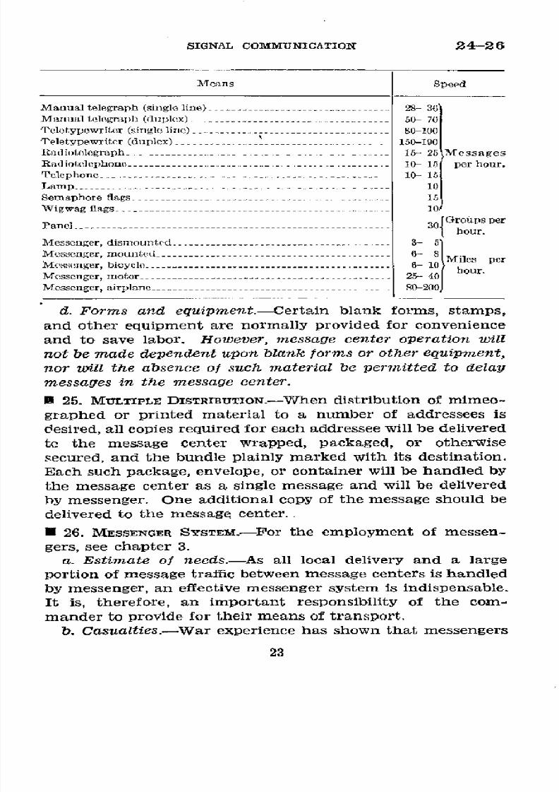
8/16/2019 (1942) FM 24-5 Signal Communication
http://slidepdf.com/reader/full/1942-fm-24-5-signal-communication 27/383
SIGNAL
COMMUNICATION
24-26
Means
Speed
Manual
telegraph
(single
line)-
-------------------------
28-
36
Manual
telegraph
(duplex) -................ 50- 70
Teletypewriter (single
line) -----------------
80-100
Teletypewriter
(duplex) ---------
........
150-190
Radiotelegraph- -------------------
- 15- 25 Messages
Radiotelephone-------
---------------- 10- 15 per hour.
Telephone
------------------
10-
15
Lamp
-10
Semaphore
flags-
.-.......................... .....--.
15
Wigwag llags
----------------------.---
10
Panel
........................................................
30
Groups
per
Panelour.
Messenger,
dismounted
1-.>...........
Messenger, mounted
......
_-.6.
- -
MS
Mo~seonger, bic~yc~lc-~6-
10 Miles
per
Messenger,
motorplane
25......--...-
--- - - 40 r
Msesengor, airplane
80-200
d.
Forms and
equipment.-Certain
blank
forms,
stamps,
and other
equipment are
normally provided
for convenience
and
to save
labor. However,
message
center
operation
will
not be
made dependent
upon
blank forms
or other
equipment,
nor will
the
absence
of such material
be permitted
to delay
messages in
the message
center.
h 25.
MULTIPLE DISTRIBUTION.-When
distribution of
mimeo-
graphed
or
printed material
to
a
number
of
addressees
is
desired,
all
copies
required for each
addressee
will
be delivered
te
the message center
wrapped,
packaged, or
otherwise
secured, and
the bundle plainly
marked with
its destination.
Each
such
package, envelope,
or container
will be
handled
by
the
message
center as
a single message
and will be delivered
by
messenger.
One additional copy
of the
message
should be
delivered to the
message center..
*
26. MESSENGER SYSTEM.-For
the
employment
of
messen-
gers, see chapter 3.
a. Estimate
of needs.-As all
local
delivery
and a
large
portion of
message traffic
between
message
centers is handled
by
messenger,
an
effective messenger
system
is indispensable.
It
is, therefore, an
important responsibility
of the
com-
mander to
provide for
their
means
of
transport.
b.
Casualties.-War
experience
has
shown
that
messengers
23

8/16/2019 (1942) FM 24-5 Signal Communication
http://slidepdf.com/reader/full/1942-fm-24-5-signal-communication 28/383
26
BASIC
FIELD
MANUAL
suffer
heavy
casualties and
that
when
these
casualties are not
promptly replaced or when insufficient men are detailed to
the messenger
service,
the
messenger personnel
is
soon
brought to the
limit
of physical
endurance.
The unit
com-
mander should,
therefore,
keep himself
informed
of the mes-
senger situation
and should be
prepared
to detail
additional
trained
messengers
whenever
they are
required.
c. Messenger dispatcher.-The m e s s
e
n
g
e r dispatcher
should be selected with care. He should
be a
forceful
non-
commissioned officer and
able
to write
rapidly; he should be
mentally alert
and
have
considerable
endurance;
and
above
all, he should
know how to
handle
his messengers with the
proper combination of understanding
and
firmness.
d. Organization.-It
may be expected that the number
of
messengers
detailed
will
be
the minimum
estimated
even
under the most favorable circumstances.
It is
vitally impor-
tant therefore that this personnel be carefully selected and
well
trained
and
that
its
transport
be
utilized
at
maximum
efficiency. As the
requirements
for messengers change
from
day
to day and even from hour to
hour,
the organization
must be flexible. This flexibility
is
enhanced if the sleeping
quarters
of
the messengers are
in
the
immediate vicinity
of
the message center. When
practicable,
messengers should
be
organized into
shifts
and details
to
provide 24-hour
service
for-
(1)
Local
delivery.
(2)
Scheduled messenger service to
other message centers.
(3)
Special
messenger service to handle urgent
and priority
messages and other special missions.
e. Training.-To
meet situations
in which heavy
casualties
among messengers or the total failure of other means of
signal
communication call for
sudden extensive augmenta-
tion in
messenger
personnel from
any
source
available,
all
military personnel
will,
as
an integral part
of their routine
training, receive the fullest
instruction
in the duties of mes-
sengers, runners, and
agents, with the object in view of
ren-
dering any
squad
or similar
grouping capable
of functioning
as an
efficient messenger
team on a
moment's
notice.
Mes-
sengers carried as
such
in Tables of
Organization
will
be
given further specialized training.
24

8/16/2019 (1942) FM 24-5 Signal Communication
http://slidepdf.com/reader/full/1942-fm-24-5-signal-communication 29/383
SIGNAL
COMMUNICATION
27
*
27.
ELECTRICAL
TRANSMISSION
OF MESSAGES.-a.
General.-
(1) It is
important
that
message center
personnel
have
suffl-
cient
knowledge
of
radio
procedure
to
enable
them
to
prepare
messages
properly
for
transmission
and delivery
when
electri-
cal
means are used;
b
and c below
are based
upon TM
11-454.
(2)
The telephone is not
considered
a satisfactory means
for a message
center to
use
in transmitting
message trafflc
because it
denies
to more
important
use the circuits
being
so
employed. If
a message
cannot
be
sent
by
telegraph,
tele-
typewriter,
radio,
or
messenger,
the writer
should
be
notified
so that
he
personally or
one of
his representatives
may com-
municate direct
with the addressee by
telephone.
The tele-
phone
in the message
center,
if installed, is not
intended
for
the
transmission
of message
traffic,
but
may
be
found helpful
in contacts with neighboring
message centers,
transmission
agencies,
and offices
relativeto
the transmission
and
delivery
of messages.
b.
Normal
form.-(1)
The
table
below
lists
the
data
of
in-
terest
to the message center,
in addition to the authentication
group,
which
should
appear, in whole or in
part, on
messages
to be transmitted by electrical
means
in the
normal form.
(2) Messages
sent from
one
headquarters to another are
addressed to and
signed by the
designation
of
the
respective
Main sec-
Part
Example
When
used
tions
Heading
.- Destination----
Send
to BA1, or send to I
Always.
Corps.
Operating
instruc- F, G, T, or Y -------------- If required.
tions.
Classification-..
..,
P, or D------------
-
If
required.
Date of
origin.
Sixteenth
-----------------
Always.
Text
------
Writer's
number_
NR26 .-------------------f available.
Addressee ..-..
...O
G-3,
I Corps
(crypto
If
essential, in-
graphed
if message
text
serted
at random
iscryptographed).
at beginning
ol
text.
Code or cipher in- DFCTOa1
--------------
If essential.
dicator.
Message ---------
IXOW
VAWL COTZ
Always.
Writer'sidentifica-
FROM
G-3, lst
Inf.
Div.
If essential,
in-
tion.
(cryptographed
if
mes-
serted
at random
sage
textiseryptographed).
near
end of
text.
Time signed
-
1828
_-_-_-- _
Always.
25

8/16/2019 (1942) FM 24-5 Signal Communication
http://slidepdf.com/reader/full/1942-fm-24-5-signal-communication 30/383
27
BASIC
FIELD
MANUAL
commanders except
when the message
is sent by a
particular
staff
officer and
action will be
expedited by
using the designa-
tion
of
the
respective
staff
officers.
Designations
of
com-
manders,
when used as addresses
and signatures,
are
not
transmitted
in messages
sent by radio,
but are inserted
in
the
proper
places on the
message
form
by the
receiving
operator
when the message
is transmitted
in the clear,
using
the
designations
indicated
by the
radio
call
signs
of
the sta-
tions
of origin and
destination.
If sent in
secret text,
the
code
clerk
making
the clear text copy
will
insert the
designa-
tions thereon.
(3) When the designation
of a staff officer is used
in
the
address or
signature
of messages sent in
the
clear by radio,
the designation
of his unit
or
headquarters
is not transmitted
but is inserted
at the headquarters
of destination as
ex-
plained in (2) above.
In messages sent
in
secret text where
the designations
of staff officers
are inserted
at random
in
the
body
of
the
message,
each
will
be inclosed
in
parentheses
and
preceded
by
an
appropriate
word
as (For
-
) or
(From
_).
They
are not cryptographed
so
as to appear
at the beginning
or end
of
the
Inessage.
c.
Abbreviated form.-The
following
table
lists the
data of
Main SO&- Part
Example When
used
tions
Heading___ Destination
-------- Send to FA1
or send to Ist
Always.
Inf.
Div.
Arty.
Operating instruc-
F,
G,
T, or Y..---------
If
required.
tions.
Classification --.. .
.
-.----------------
Urgent
message
only.
Text --
Addressee
--.------
TO
CG DIV ARTY
(cryp-
If
essential,
in-
tographed
if message
text
serted at
random
is
cryotographcd). near beginning
of
text.
Code or
cipher DFCTI
------------------f
essential.
indicator.
Message -----------
I X O W
VAWL COTZ
Always.
UKZH.
Writer's
identifi-
FRO.I CO
1ST INF
(cryp-
If essential, in-
cation.
tographed if message text serted at
random
is cryptographed).
near
end of text.
Time signed
-- L----926 .-.
____._.__._._______ Always.
26
8/16/2019 (1942) FM 24-5 Signal Communication
http://slidepdf.com/reader/full/1942-fm-24-5-signal-communication 31/383
SIGNAL
COMMUNICATION
27-28
interest
to
the
message
center,
in
addition
to
the
authentica-
tion
group,
in whole
or
in
part,
on
messages
to
be
transmitted
by
electrical
means
in
the
abbreviated
form.
U 28.
ARMY
AND
NAVY
METHODS
OF SPECIFYING
TIME.---a.
The
Army
and
the
Navy
use
the
24-hour
clock.
In the
24-hour
clock,
time is
always
expressed
as
a group
of
four
numerals.
The
first two
numerals
of
the
group
denote
the
hour
and
the
last
two
numerals
the
minute
after
the
hour.
Ordinary
or
12-hour
time
may
be
converted
to 24-hour
time
by
adding
12 hours
to
all
times
from
1:00
PM
to
midnight,
inclusive.
b. The date
may
be
expressed
in
either
of
two
ways:
(1)
For
the
current
month,
the
day
may
be
indicated
by
preceding
the
four-digit
time
group
with
a
two-figure
date
group,
indicating
the
day
of
the
month.
For
example,
080600
is
the
8th
day
of
the
month
and
the
time
is
6:00
AM.
(2)
The
date
and
time
may
be
stated
by
using
the
four-
digit
time
group,
followed
by
the
month,
day,
and
if
desirable,
the
year.
c. The
heading
of
all
messages,
dispatches,
reports,
and
orders
transmitted
by radio,
telegraph,
or
cable
to
the
War
Department
will
include
the
date
and the
time
of
origin
expressed
by
six
digits
as
prescribed
in
b(1)
above.
The
aate
group,
time
group,
or
date-time
group
may
be omitted
from
messages,
dispatches,
reports,
and
orders
transmitted
by radio
in
the
abbreviated
form
or
abbreviated
normal
form
when necessary.
d.
Greenwich
Civil
Time
is
used
within
the
Navy
and
in
joint
operations,
unless
otherwise
prescribed,
and
within
the
Army,
in
both
the
heading
and
text
of
all
communication
in
the
following
categories:
(1)
Messages
and
orders
from
the
War
Department.
(2)
Messages
and
reports
to the
War
Department.
(3)
Orders,
reports,
and
other
communication
between
headquarters
not having
common
local
time.
(4)
Communication
with
the
armed
forces
of
associated
nations.
e.
All
the
groups
expressing
Greenwich
Civil
Time,
includ-
ing
those
in
the
headings
of
messages,
will
be designated
by
the
letter
suffix
Z immediately
following
the
last
digit
of
the
group.
For
example,
190225Z
indicates
2:25
AM
on the
19th
day
of
the
current
month
Greenwich
Civil
Time.
27

8/16/2019 (1942) FM 24-5 Signal Communication
http://slidepdf.com/reader/full/1942-fm-24-5-signal-communication 32/383
28-32
BASIC
FIELD
MANUAL
f.
Examples
of
time
expressed
in
the
12-hour
and
24-hour
clock
systems
are
shown
below.
12-hour
time
4-hou
time
12-hour
time
24-hou
time
Midnight
-{
24--
000
Non
-1200
2400
12:01
AM
-.
_.
0001
12:59
P
1259
1:17
AM
.....
-......
0117
6:
08
PM
----
1808
11:
35 AM
...
-.....
1135
11:159
PM-
2359
*
29.
STATION
LISTS.-Operation
of
the
message
centers
of
di-
visions
and
higher
units
is
facilitated
when
station
lists
are
provided.
The
station
list
is
prepared
by
the
adjutant
general
or
G-1
of
the
unit,
and
gives
the
location
of
the
various
head-
quarters
and
elements
of
the
command.
*
30.
TELEPHONE
DIRECTORY.-In
signal
operation
instruc-
tions,
the
message
center
is
furnished
the
telephone
directory
names
of
all
switching
centrals
and
the
numbers
of
all
tele-
phones
with
which
it
may
be
concerned.
Telephone
directory
names
and
numbers
are
not
intended
for
secrecy
but
may
be
prescribed
for
purposes
of
simplicity,
accuracy,
and
speed
in
handling
telephone
calls.
(See
par.
175
and
example,
par.
265m.)
*
31.
RADIO,
TELEGRAPH,
AND
VISUAL
CALL
SIGNS.-Call
signs
are
issued
in
blocks
to
the
unit
signal
officer
by
the
next
higher
echelon.
In
signal
operation
instructions,
the
message
center
is
furnished
a
list
of
the
call
signs
of
stations
with
which
it
may
be
concerned.
These
call
signs
are
used
by
the
message
center
to
expedite
the
handling
of
messages.
All
stations
serving
the
same
headquarters,
whether
radio,
tele-
graph,
or
visual, use
the
same
call sign.
However,
when
there
is
danger
that
the
enemy
may
intercept
visual
signals
and
identify
the
station,
a
separate
call
sign
may
be
prescribed
for
visual
stations.
(See
example,
par.
265e.)
*
32.
AUTHENTICATION
SYSTEMS.-An
authentication
system
may
be
prescribed
for
use
with
messages
transmitted
by
any
28
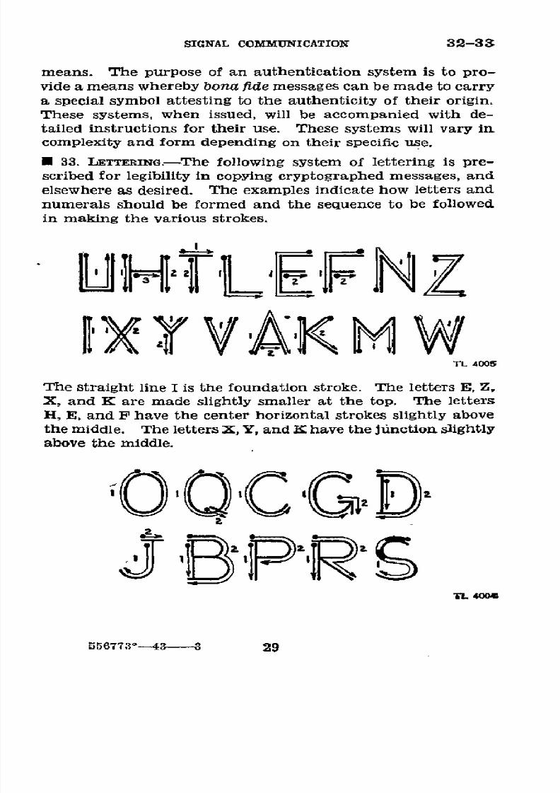
8/16/2019 (1942) FM 24-5 Signal Communication
http://slidepdf.com/reader/full/1942-fm-24-5-signal-communication 33/383
SIGNAL
COMMUNICATION
32-33
means. The
purpose of an authentication
system is
to pro-
vide a means whereby
bona
fide messages
can
be
made
to
carry
a special
symbol attesting to
the
authenticity
of
their
origin.
These
systems,
when
issued,
will
be
accompanied
with de-
tailed
instructions
for their use. These systems
will
vary
in
complexity
and form depending
on their specific
use.
* 33. LETTERING.-The
following system
of lettering
is pre-
scribed for legibility
in
copying
cryptographed
messages, and
elsewhere
as
desired.
The
examples
indicate how letters and
numerals
should
be
formed
and the sequence
to be
followed
in
making
the
various
strokes.
iixYVAKHM
TL 4005
The
straight line
I is the foundation
stroke. The
letters
E,
Z,
X,
and
K
are made
slightly
smaller at the top. The
letters
H, E, and
F
have the
center horizontal
strokes slightly above
the
middle.
The
letters
X,
Y,
and K have
the junction
slightly
above
the
middle.
j3
E
P ,R 9
T6773--0
556773°43
3
29

8/16/2019 (1942) FM 24-5 Signal Communication
http://slidepdf.com/reader/full/1942-fm-24-5-signal-communication 34/383
33-34
BASIC
FIELD
MANUAL
The
letters
O,
Q,
C,
and
G
are
made
in
circular
form.
The
letter
B
is
slightly
smaller
at
the
top
and
has
the
center
horizontal
part
slightly
above
the
middle.
The letters
R
and
S
are
slightly
smaller
at
the
top.
678400
The
bar
under
the
numeral
1,
the
top
of
the
5
and
7,
and
the
bottom
of
2,
are
straight
lines.
The
numeral
1
has
a
bar
under
it,
slightly
below
the
stem, to
distinguish
it
from
the
letter
I
and
the
cipher
O
has
a
bar
diagonally
through
it
to
distinguish
it
from
the
letter
O.
*
34.
CHARTS,
MAPS,
AND
DIAGRAMS.-The
items
given
below,
particularly
in divisions
and
higher
headquarters,
are
help-
ful
in
conducting
the
operations
of
the
message
center.
In
order
to
be
of
value,
they
must
be
kept
up
to
date.
a.
A
display
map
to
show
the
locations
of
headquarters
of
the
next
superior
and
of
the
next
subordinate
units,
the
scheduled
messenger
routes,
and
other
information
which
would
be
useful
to messengers.
Sufficient
maps
or
map
sub-
stitutes
of
the
area
to
provide
each
messenger
with
copies
should
be
available.
b.
A
corresponding
diagram
of
the
locations
of
the
several
offices
at
the
local
headquarters,
possibly
showing
the
names
of
the
principal occupants
of
those
offices.
c. A
ready
reference
chart
showing
the
various
means
of
signal
communication
established
to
the
different
units
pre-
pared
in
substantially
the
following
form
and
with
pins
placed
in
appropriate
spaces
to
indicate
the
means
which
are
established.
(See
par.
46a.)
30

8/16/2019 (1942) FM 24-5 Signal Communication
http://slidepdf.com/reader/full/1942-fm-24-5-signal-communication 35/383
SIGNAL
COMMUNICATION
34-36
Unit
Messenger
Telegraph
Telephone
Radio
16
Inf
.---
18
Inf
--
.......
-------.......
. .
...
26
Inf
f..
...
8Div
Arty.
d. A list of officers on duty with
the unit.
e.
A duty
chart of
message center
and
messenger
person-
nel,
which also should provide a meal schedule.
*
35.
ABBREVIATIONS.-In
indicating
the
means
by
which
messages may
be transmitted,
the following
abbreviations
are used:
Msg
_______________
Message
Msg
Cen__-----------
Message
center
Msgr--------------- Dismounted messenger
(runner)
Ap Msgr__----------
Airplane
messenger
Bcl Msgr___________.
Bicycle
messenger
M Msgr___---------.-
Motor
messenger
Mtcl
Msgr----------
Motorcycle
messenger
Mtd
Msgr_
---
__-.
Mounted
messenger
Scd Msgr_
--------
Scheduled messenger
Sp
Msgr__------__--
Special
messenger
Pgn______-----
_----
Pigeon
Rad --------------- Radio
Tg_________________
Telegraph
Tt
-________----
_-
Teletypewriter
Tp_________________
Telephone
Vis___-___---------- Visual
SECTION
II
PROCEDURE
FOR
DIVISIONS
AND
HIGHER
UNITS
l* 36. ORGANIZATION.-a.
In
describing the
procedure for divi-
sions and
higher units,
duties are outlined
for message
cen-
ter
chief,
messenger
dispatcher,
code clerk,
messengers,
and
operators
of the
several
means
of
signal
communication.
31
8/16/2019 (1942) FM 24-5 Signal Communication
http://slidepdf.com/reader/full/1942-fm-24-5-signal-communication 36/383
36-37
BASIC
FIELD MANTAL
This
division
of duties
is
functional and
is
made for con-
venience
in description.
In small
message
centers
during
periods
of inactivity,
one man
may perform
two or
more
functions
while
in
large
and
busy message
centers,
two
or
more
men
may be
required for a
single function.
b.
The
term "message
center chief"
is applied
to
the
senior
specialist on duty.
c. The
term
"operator"
includes telegraph,
teletypewriter,
and
radio operators.
*
37.
EQUIPMENT
AND
FoRMs.-There
is
no guarantee
that
all
messages
arriving
at
a
message
center for transmission
will
be
on standard
forms and
properly
prepared.
Neverthe-
less,
the
responsibility
of
the message
center
begins
when
the message
is presented
to
it
by
the writer,
regardless
of
the manner
or form of presentation,
and every effort
will be
made to
insure
its rapid
and accurate
transmission
to the
addressee.
The
following equipment
and
forms
are
helpful-
although the
procedure may
be
used
without
them:
a.
Received
stamp.-The received
stamp indicates
in per-
manent
type the
message
center
designation;
in movable
type,
the
month,
date,
and
year; it
also
provides
for
time
entry
by clock
operated stamp.
b.
Serial
number stamp.-This
is
an automatic
numbering
stamp.
c. Field message
book.-This
book contains
message
blanks
for
all
messages, special tissue
blanks
for
pigeon messages,
and
several
vellum
sheets for
making
map
overlays.
d. Number
sheet.-The
following
is
an extract from
W. D.,
S.
C.
Form No. 159.
The
complete
form provides
space
for
100
messages.
(See
par.
46a.)
32

8/16/2019 (1942) FM 24-5 Signal Communication
http://slidepdf.com/reader/full/1942-fm-24-5-signal-communication 37/383
SIGNAL COMMUNICATION
37
WAR
DEPARTMENT
SIGNAL
CORPS, U. S. ARMY
NUMBER
SHEET
(Unit)
(Date)
No.
Remarks
No.
Remarks
No. Remarks
No. Remarks
-1--- - 26------
51------
76 ...
2
-27 52
-----------
77
...
- I
e.
Delivery
lists.-(1) The
following
is an extract
from
W. D.,
S. C.
Form No. 160.
The
complete
form provides
space
for
seven messages.
WAR
DEPARTMENT
SIGNAL CORPS,
U. S. ARMY
LOCAL DELIVERY
LIST
Time
dispatched
Time
returned
MESSAGE
IDENTIFICATION
SIGNATURE IN FULL
IDENTIFICATION
33
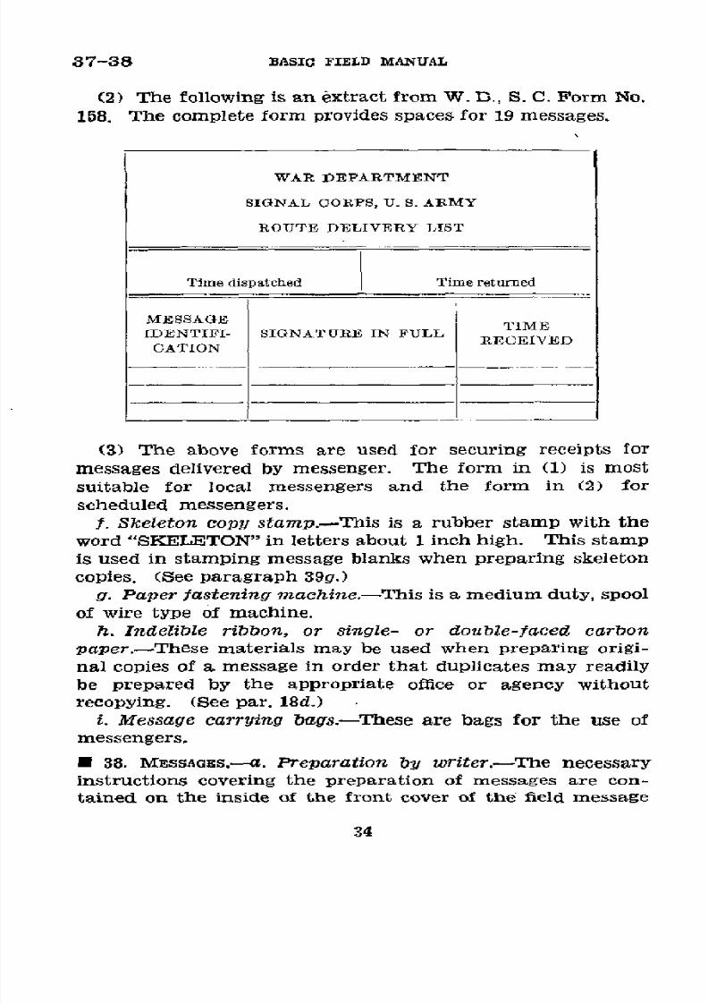
8/16/2019 (1942) FM 24-5 Signal Communication
http://slidepdf.com/reader/full/1942-fm-24-5-signal-communication 38/383
37-38
BASIC FIELD
MANUAL
(2) The
following
is
an
extract
from W.
D., S. C.
Form
No.
158. The complete
form provides
spaces
for 19
messages.
WAR DEPARTMENT
SIGNAL
CORPS,
U.
S.
ARMY
ROUTE
DELIVERY
LIST
Time dispatched Time returned
MESSAGE
IDENTIFI-
SIGNATURE IN
FULL
TIME
RECEIVED
CATION
(3)
The above
forms
are
used
for
securing receipts
for
messages delivered
by
messenger.
The
form in (1)
is
most
suitable for
local messengers
and
the
form in (2) for
scheduled messengers.
f.
Skeleton
copy stamp.-This
is
a
rubber
stamp
with the
word "SKELETON"
in
letters
about
1
inch high. This
stamp
is used
in
stamping
message
blanks
when
preparing
skeleton
copies. (See
paragraph
39g.)
g. Paper fastening machine.-This
is
a medium duty,
spool
of
wire type
of machine.
h. Indelible
ribbon,
or
single- or double-faced
carbon
paper.-These
materials may
be used when
preparing
origi-
nal
copies
of
a message
in
order that duplicates
may readily
be
prepared
by
the appropriate
office
or
agency
without
recopying. (See par.
18d.)
i. Message carrying bags.-These are
bags
for
the
use
of
messengers.
*
38. MESSAGES.---a.
Preparation
by writer.-The
necessary
instructions
covering the
preparation of messages
are
con-
tained
on the
inside
of the
front
cover of the
field message
34
8/16/2019 (1942) FM 24-5 Signal Communication
http://slidepdf.com/reader/full/1942-fm-24-5-signal-communication 39/383
SIGNAL COMMUNICATION 38
book.
The
following are the essential
instructions
contained
in the message book:
(1)
The
preparation
of
at
least
two
carbon
copies
is
re-
quired, the
original
and one carbon to be delivered
to the
message center
and the other carbon copy
to be retained for
the
writer's file.
(2)
Print plainly.
proper names
(except
signature
and grade
of
writer)
and code
and
cipher
groups
in
capital
letters.
(3) Write the
message in
as
few
words
as possible.
If the
writer
desires
punctuation
marks
transmitted,
they must
be
spelled out,
otherwise they will
not be
sent.
(4)
Use
only
authorized
abbreviations.
(5)
If
a precedence in speed
of
handling
other
than routine
is
desired, print
in capital
letters
the desired
precedence
in
the space
at the upper right of the message
form.
(6) The use
of a serial
number
by the writer
simplifies
future
reference
by
either
the
writer
or
the
addressee.
The
number is inserted on the first line
of
the message form
after
the
word "No."
(7) After the word
"Date" insert the
date
in
the following
order: Day,
month,
year (example:
15
January 1941
or
15
Jan
41).
(8)
After the
word "To" on the
message form
insert
the
official
designation
of
the
addressee (example:
CG 1st
Inf
Div).
Add
his actual
location only
when necessary
to in-
sure
delivery.
Do not
use
the
telephone
directory
designa-
tions
as addresses.
(9) In
the blank
following
"Official
designation
of sender"
insert
the official
capacity in which
the writer
is serving (ex-
amples:
"CO 1st
Bn
1st
Inf"
or
"Leader
Patrol
No. 1").
(10)
In the blank
following "Time signed"
enter
the time
at
which
the
message
is
signed.
This blank
must
always
be
filled.
(11)
In the
blank
following
"Signature
and
grade of
writer" insert the personal
signature
of
the writer
of the
message
or
of
the person authorized to write the message
for him.
(12)
In
time of war or
emergency all messages
to be trans-
mitted
by
radio,
or
by
other
means
when
danger
of
hostile
35

8/16/2019 (1942) FM 24-5 Signal Communication
http://slidepdf.com/reader/full/1942-fm-24-5-signal-communication 40/383
38
BASIC FIELD
MANUAL
interception
exists,
are cryptographed
unless
authority
to
send in
clear
is
given
by the commanding
officer
or
his
authorized representative.
This
authority must
be
indicated
in
lower
left corner.
A box is
provided
in
the message
form
to
authorize
transmission in
clear.
THE:SISPACES
OR ME~SAGE ENTE~R
Ny
IME FILED
|SI
MSG CEN
O.
SENT
_ URGEN
T
MT
TO
ESS(AGE
CLSIFIC
ON
MlCESSAGE
NTEIR
N
DUPLICATE)
No. 3
DATE
2/
JULY
/_e4/
To
CGZ CORPS
'/VEA/1Y
/ ,R9CES
4AV/E
CHEC/tED
O¿/R'
AIDVAN/CE
PER/OD
/f9£Qa3T?
RE/MVORCk
c/VTS
C<
¡S
\57^//V
fV /V I
IUIHORIEID U 3IE
.,II,<,G5E>
,<C
G
SENT IN C
LAR
SIONATURE.OF
FICER
6SIONATURENOD
RADE OF WRITlR
7T-.4022A
'IGnRE
1.-Example
of
a
message properly prepared
by
the writer.
b. Address and
signature.-When
call
signs are used
for the
transmission
of
a message, only
the commanding
officers of
the
units
which
the stations serve
are indicated.
However,
the individual
for whom
the message
is intended or
his
official
title
may
be inserted
at
random
within
the body
and
near
the beginning
of the
message
preceded
by the
word
"For", and
the identity
of
the
writer
of the message
near the
end of the
message
preceded
by the
word
"From."
The
position
of
these insertions
must
be varied in
order to maintain
crypto-
graphic
security.
36

8/16/2019 (1942) FM 24-5 Signal Communication
http://slidepdf.com/reader/full/1942-fm-24-5-signal-communication 41/383
SIGNAL
COMMUNICATION
38-39
c.
Receipt.-The
receipt
of
an
addressee
for a
message
con-
sists
of
his
signature
and
the
time
at
which
he
receives
the
message.
d. Acknowlecdgment.-An
acknowledgment
of a
message
en-
compasses
not
only
the fact
that the
message
was received
but
also
that
the
addressee
understands
the contents
of
the
message.
When
directed
by
the
writer
of
a
message,
the
addressee
may
be informed
that
an acknowledgment
of
the
message
is
requested.
The
receipt
indicated
above
is
ade-
quate
for
the
acknowledgment
provided
the
addressee
under-
stands
that
his
receipt
encompasses
this
additional
require-
ment.
If, however,
a study
of
the
message
is
required
prior
to an
acknowledgment,
the addressee
may
initially
receipt
for the
message
and
at
a later
time
acknowledge
it.
* 39.
HANDLING
OUTGOING
MESSAGES.-The
procedure
pre-
scribed
in
this
paragraph
and
paragraph
40 applies
specifi-
cally
to
messages
not
classified
as secret;
these
messages
are
treated
as
confidential.
The
procedure
for
handling
mes-
sages
marked
"Secret"
differs somewhat
and
is
described
in
paragraph
41.
An
authentication
system
may
be
used
at
message
centers
to indicate
or determine
the authenticity
of
messages.
Outgoing
messages
coming
to
a
message
center
from a
local
source
may
be
handled
by
the separate
specialists
listed
below
in
the
manner
described:
a.
Message
center
chief.-The
message
center
chief-
(1)
Receives
the
message
in
duplicate
from
the
writer,
his
representative,
or
a messenger,
making
sure
that
the person
submitting
the message
is
known
to
him
or
can satisfactorily
identify
himself.
(2)
Immediately
inspects
the
message
for
legibility
and
proper
address.
He
declines
to accept
illegible
and
improp-
erly
addressed
messages
and,
if necessary,
brings
such
mes-
sages
immediately
to
the attention
of
the
message
center
officer.
(3) Writes
the
time
filed on
both
copies
of the
message
or
stamps
the
time
of
receipt
on
the
back
of
both copies
with
his
received
stamp.
(See
fig.
2.)
(4)
Writes
or
stamps
the
message
center
number
with
his
serial
number
stamp,
beginning
a
new
series
of numbers
at
midnight
each
day.
(See
fig.
2.)
37
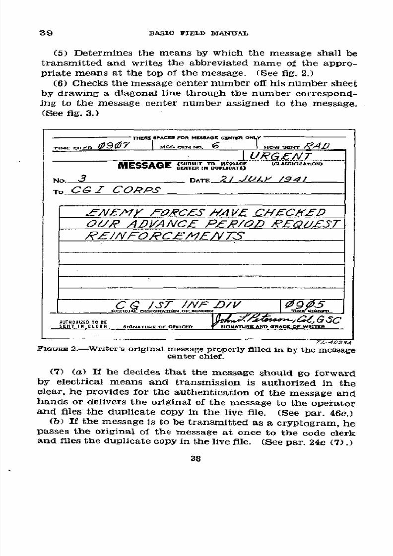
8/16/2019 (1942) FM 24-5 Signal Communication
http://slidepdf.com/reader/full/1942-fm-24-5-signal-communication 42/383
39
BASIC
FIELD MANUAL
(5)
Determines
the means
by which
the
message
shall
be
transmitted
and
writes
the
abbreviated
name
of the
appro-
priate
means
at
the top
of
the
message.
(See
fig.
2.)
(6)
Checks
the
message
center
number
off
his number sheet
by
drawing a
diagonal
line
through
the
number
correspond-
ing
to
the
message
center
number assigned
to
the message.
(See fig.
3.)
TNESESPACES
OR
MESSAGE
EI~ER ONLT
TlME
FILFO
(9(7
NMSG
RN
ND. I
OW SENT
A
I
URGEWT
MESSAGE
(
SUBMIT TO ME.SSA.E
(ClAS....TI.)
CMES
ER IN
DUPLICATE>
No.
3
DATE
2/ JÚ--YL
/941
To
CG
Z CORPS
¿LNWEAY
f/ORCES
HA/VE
CH-EChKED
O¿/R
ADV1ANCE
PLPR/OD
R£L¿4.1T
,9E//VffORCPC1EVA'S
C
ç /ST
/1/
/
Isr196
AUTHORIEOO
OBE,
SEHNTN,
CLER SIGNATURE
F OPFiCR
SlIGNATURIAND
GRADEOF
WRITER
7T-4023.4
FIGURE
2.-Wrlter's
original
message
properly
filled in
by
the
message
center chief.
(7)
(a) If he decides
that the
message
should
go
forward
by
electrical
means and transmission
is
authorized
in
the
clear,
he
provides
for
the
authentication
of
the message
and
hands
or delivers
the original
of
the
message
to
the
operator
and
files the
duplicate
copy
in the live file.
(See par.
46c.)
(b)
If the
message
is to
be
transmitted
as
a
cryptogram,
he
passes
the
original
of
the
message
at
once
to
the
code
clerk
and
files the
duplicate copy
in
the live
file.
(See par.
24c (7).)
38
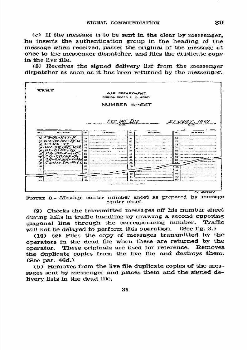
8/16/2019 (1942) FM 24-5 Signal Communication
http://slidepdf.com/reader/full/1942-fm-24-5-signal-communication 43/383
SIGNAL
COMlMUNICATION
39
(c)
If the message
is
to
be
sent in the
clear by
messenger,
he
inserts
the authentication
group
in the
heading
of
the
message when
received, passes
the
original
of
the
message
at
once
to the messenger
dispatcher,
and
files
the duplicate
copy
in the
live
file.
(8)
Receives
the signed
delivery
list from
the messenger
dispatcher
as
soon
as
it has been
returned
by
the
messenger.
WAR DEPARTMENT
SINAL
CORPSU. S, ARMY
NUMBER
SHEET
1«L__
bOS
INF
DI
Y
2/
' CG-AC-R2d
P.
___
.
~..........
°
........
PG-A-T
..............
~
.r
S.. I
..
_.
..
.....
..
_..
. . .
. U
..........................
.
10I.
-
..
1
,
_
.
_
................
-------------------
---------
-
------------
II
-'57
… _ JS….
........ ... _._..............
--.---.
5 --------------
-.
FIGURE
3.-Message
center
number
sheet
as
prepared
by
message
center
chief.
(9)
Checks
the
transmitted
messages
off
his
number
sheet
during
lulls
in
traffic
handling
by drawing
a second
opposing
diagonal
line
through
the
corresponding
number.
Traffic
will
not
be
delayed
to
perform
this operation.
(See
fig.
3.)
(10)
(a)
Files
the
copy
of
messages
transmitted
by
the
operators in
the
dead
file when
these
are
returned
by
the
operator.
These originals
are used
for
reference.
Removes
the duplicate
copies
from
the live
file
and destroys
them.
(See
par. 46d.)
(b) Removes
from
the
live
file
duplicate
copies of
the mes-
sages
sent
by messenger
and
places
them
and the
signed
de-
livery
lists in
the dead
file.
39
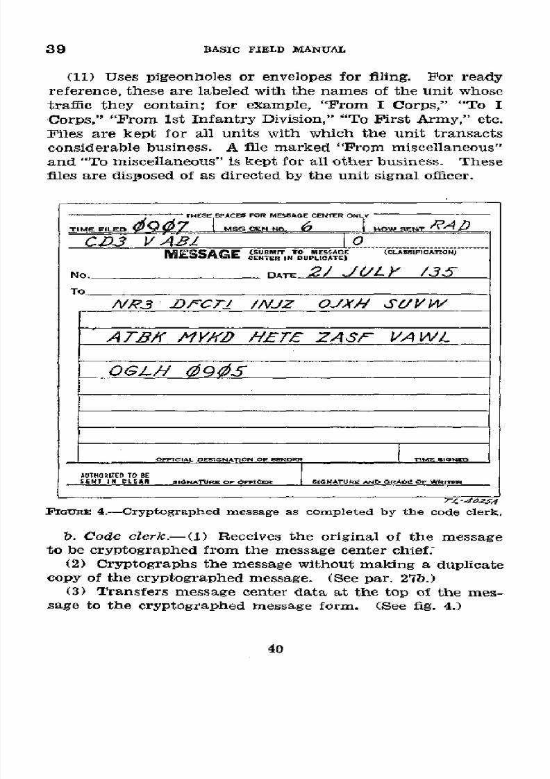
8/16/2019 (1942) FM 24-5 Signal Communication
http://slidepdf.com/reader/full/1942-fm-24-5-signal-communication 44/383
39 BASIC FIELD
MANUAL
(11) Uses pigeonholes or
envelopes
for filing. For ready
reference,
these
are
labeled with the
names of
the unit
whose
traffic
they
contain; for
example,
"From
I
Corps,"
"To
I
Corps," "From
1st Infantry
Division," "To First Army,"
etc.
Files
are
kept
for
all units
with
which
the unit transacts
considerable business. A file
marked
"From miscellaneous"
and
"To
miscellaneous" is kept
for
all other
business. These
files
are
disposed
of as
directed by the unit signal officer.
·
4
40
CPACER.OR MESSAGE
rENT5R oNY -
CSz3 1V
ABI
1 O.........
MESCZ:^
SBIT
TO MESSAGE
.(CL.S...CAT.ON
MES~Wé;E
SA
'CE"ETRN
DUPLICATE)
No.
DTE
2/ J / )
/35
To
ANR3 P
CZ7
//VJZ
OJXHA/
S¿/VW
AT7B/ MY/D
H1F £E
ZASF VAWL
OFFICIALDE SGNATION F ENOR
IE IN
AUTHORIZEDO BE
SENT
I N
CLEAN I*ONAfURK
F OFFICER SIGNATUREANDGRADI
OF WRI rIO
;7- -4025
FIGURE 4.-Cryptographed message
as completed
by the code
clerk.
b. Code
clerk.-(1)
Receives
the
original of
the
message
to be cryptographed from the
message
center chief.
(2) Cryptographs
the
message
without making
a duplicate
copy
of
the cryptographed message. (See
par. 27b.)
(3)
Transfers message center
data at
the top of the
mes-
sage to the
cryptographed
message form.
(See fig. 4.)
40

8/16/2019 (1942) FM 24-5 Signal Communication
http://slidepdf.com/reader/full/1942-fm-24-5-signal-communication 45/383
SIGNAL
COMMUNICATION
39
(4)
Indicates
the
pertinent
data
as
to address,
operating
instructions,
speed
in handling,
and
authentication
group
(if
predetermined)
in
the
heading
of
the
cryptographed
mes-
sage. (See
flg.
4.)
(5)
Passes the
cryptographed
message
to
the operator,
or
to the
messenger
dispatcher
when
the
message
is
to
go
via
messenger.
TrES~EPACESFOR M.ESAGE
CENTERO
TIME
FlE MSG
CN
NO HOW SENT
RAD
CD3
V AB
R2
O
G-/2_12
MESSAGE
SIBSITTU
M.SAE
.
ESAE NTERIN
UPLICATE)CSSIFICTION)
No.
DoAr
2/
JUL
/35
To
VNR3
D-C_
/_/JZ
OJXH
S'/VW
AT7 BK
YK
HIETE
ZASF
VIAWL
OGLf/-t
95
OPFICIAL.
IESIONA TION
E
S
F
SEDhTIME
AUTHORIZED
O BE
DUIIZ 15 srJ
OTCEA
SICAT
SiGNATURE
ANDGRADE
Or
WRrITE
T£-4026A.
FIGTE
5.-Message
after
completion
of transmission
by the
operator.
(6)
Files
the
original
of
the
clear
text
message
in his
file
and disposes
of
the
file
as
directed
by
the
unit
signal
or
com-
munication
officer.
(7)
Destroys
all
work sheets
by
burning.
c. Operator.-(1)
Receives
the
cryptographed
text
message
from
the
code clerk
or
the clear
text
message
from
the
mes-
sage center chief.
(2)
Inserts
a group
count
and
a
station-to-station
serial
number.
(See
fig.
5.)
41
8/16/2019 (1942) FM 24-5 Signal Communication
http://slidepdf.com/reader/full/1942-fm-24-5-signal-communication 46/383
39
BASIC
FIELD
MANUAL
(3) Transmits
the
message
and receives
a receipt from the
distant operator.
(See par.
27b.)
(4)
Services
the
message
in
his
possession
and
when
he
no
longer needs it for
verification,
returns
it to
the
message
center
chief
for
file.
(See a (10)
(a)
above
and fig. 5.)
d. Messenger
dispatcher
(see also f below)
.-
The
messenger
dispatcher, who
is
charged
with
the
supervision
of
messen-
gers-
(1)
Receives
the original
of a
clear
text message
from the
message center chief
or the
crytographed
message
from the
code
clerk.
(2)
Prepares
a delivery list in
duplicate
for transmission
by
messenger.
A good carbon copy is necessary; this copy
is
retained
by
the messenger
dispatcher.
(3)
Enters a
serial number
at the upper right of
the
delivery list
form.
(See
fig. 6.)
(4) Enters
the
message center number
or other
means
of
identification
in
the
first
column of
the
delivery
list.
(See
fig.
6.)
(5)
Stamps or
writes
the time dispatched in
the
blank space
at the
upper
left of the
delivery
list
just
prior to
the
departure
of the messenger. (See fig. 6.)
(6)
Hands the dellvery list and
the messages
to
the
mes-
senger and
gives
him any
necessary
special instructions.
(7)
Stamps
or
writes the
time returned in the blank space
at
the
upper
right
of
the
signed
delivery
list
when
it
is
re-
turned
by the messenger. (See
fig. 7.)
(8)
Hands the completed
delivery
list to
the message
center
chief.
(9) Disposes
of duplicate
delivery
lists
as
directed
by
the
unit signal
or
communication
offricer.
e. Messenger
(see
also
f below).-The
scheduled or special
messenger-
(1)
Receives
the
message(s)
and
delivery
list
from
the
messenger
dispatcher and proceeds to
the distant
message
center
(or addressee if the
addressee
is not
served by
a
mes-
sage
center).
(2) Delivers
the message(s)
and
delivery list
to the
message
center chief
of
the distant message
center
or to the
addressee
who signs
for
each
message
and,
in the case
of the route de-
42
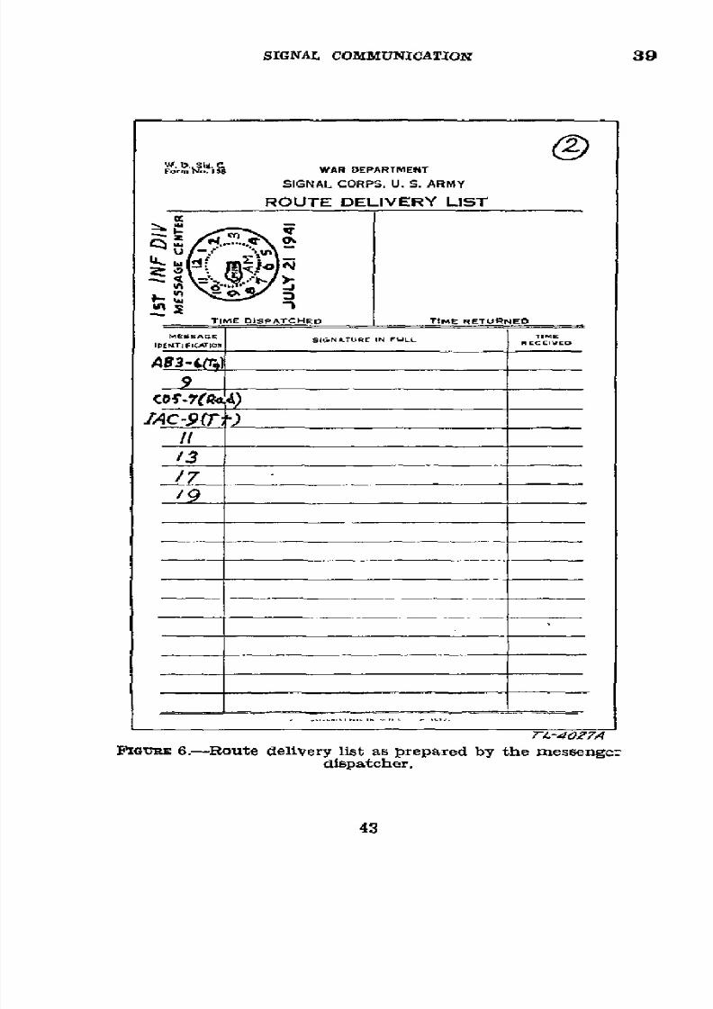
8/16/2019 (1942) FM 24-5 Signal Communication
http://slidepdf.com/reader/full/1942-fm-24-5-signal-communication 47/383
SIGNAL
COMMUNICATION
39
FSm'
s
~WARDEPARTMENT
SIGNAL CORPS. U. S. ARMY
ROUTE
DELIVERY LIST
TIME DISPATCHEO TIME RETURNED
MEtSSAGE
SIGNATUR
E
INFULL
riE
L.NTiJFICATIE
AB3-4lr)
IAC-7(T)
_1
'13~43
LIGT..BE
6.-Route
delivery
list
as prepared
by
the
messengc:
dispatcher.
43
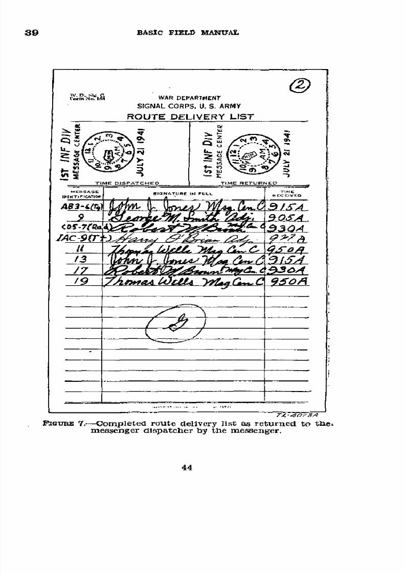
8/16/2019 (1942) FM 24-5 Signal Communication
http://slidepdf.com/reader/full/1942-fm-24-5-signal-communication 48/383
39
BASIC FIELD MANUAL
{:orm"o,~<iP WAR
DEPARTMENT
SIGNAL CORPS. U. S. ARMY
ROUTE DELIVERY
LIST
TIME DISPTCHEO TIME RETURNEO
MEssengr
d
INpaTUcr
b
N
FULLessen
944~
'054
/3 U
1
_____ -
9I
7Mib~, e /J/L4-
`)t~ r
C O0A
MrG"
7..-Completed
route
delivery lIst as returned
to the:
messenger dispatcher by the messenger.
44

8/16/2019 (1942) FM 24-5 Signal Communication
http://slidepdf.com/reader/full/1942-fm-24-5-signal-communication 49/383
SIGNAL
COMMUNICATION
39
livery
list, enters
the
time
of
receipt in the
right-hand column.
(See fig. 7.)
(3)
lZeceives
the
signed
delivery
list
from
the
message
center chief
of the distant
message center
or
from
the ad-
dressee and either returns to
his
message
center or
continues
to other message centers or addressees on his route if he has
other deliveries to make.
(4) Enters
his
name,
his initials,
or
his number
as pre-
scribed by
local regulation,
on
the
delivery list for
identifica-
tion. (See fig. 7.)
(5)
Hands
the
delivery
list
to
the
messenger
dispatcher
of
his own message center.
f. Scheduled messenger service.-(1) Routine messages.-
For scheduled messenger
service,
the delivery list is handled
as
follows:
(a) When a
scheduled messenger has
just
departed
on a
certain scheduled route and
the next
message for delivery on
that
route
reaches
the
messenger
dispatcher's
desk,
the
latter
enters
the
message center number or other
message identifi-
cation in the first column of a serially numbered delivery list.
He enters
succeeding
messages
for that
route
on
successive
lines as they arrive.
(b) When the time scheduled for the
next
messenger's
departure arrives, the messenger dispatcher
enters or stamps
the
time
dispatched
in
the
proper
space,
turns
the
delivery
list and
messages over
to the messenger,
and
gives
him such
instructions as
may
be
necessary.
(c) The messenger
delivers the messages
according to his
standing
instructions
supplemented by
such special
direc-
tions as he may have received
for
the
particular
run. He
secures
a
signature
for
each
message.
(2)
Other
messages.-Delivery
of
urgent, operational
priority,
and
priority
messages
will
not
be
held
up
for
a
scheduled
messenger.
g. Skeleton
copy of message.-Some
messages
will
be
sub-
mitted
to the message
center
without
a duplicate copy. For
transmission by electrical
means,
the single
copy
will suffice,
but
if
transmission is by messenger,
a skeleton copy is made
for
follow-up
and
this
copy is thereafter handled
as
a dupli-
cate
copy.
The
skeleton copy is
usually brief; for
a 100-
556773-43
45

8/16/2019 (1942) FM 24-5 Signal Communication
http://slidepdf.com/reader/full/1942-fm-24-5-signal-communication 50/383
39-40
BASIC
FIELD
MANUAL
word message
relating
to
class
I
supplies,
the
skeleton
copy
might
be
simply,
"QM
to
Army
QM Class
I
supplies,"
or
for
a bundle
of
maps,
"G-3
to
G-3,
26
Inf
Div
bundle'
maps."
A
very
brief description
is
all
that
is
required
for identifica-
tion.
An
urgent
or
priority
message
is
not delayed
for the
preparation
of
a
skeleton
copy.
If
a skeleton
copy
is re-
quired,
it is
made
as
accurately
as possible
from
memory
after
the
message
has
been
dispatched
and
the notation
"From
memory"
is added.
U 40.
HANDLING
INCOMING
MESSAGES.-Messages
received
at
a
message
center for
delivery
to local addressees
may be han-
dled
in the manner
indicated
below.
Incoming messages
are
not assigned
message
center
numbers.
a. Operator.-(1)
Copies
the message
in
duplicate.
(2)
Services the
message,
entering
the
time
he acknowl-
edged
receipt
and
his
personal
sign
under
the
message,
in-
closed
in
a
circle.
(See
fig.
8.)
(3) If the
message
is
in
the
clear,
inserts
the
address
and
signature
or completes
them
by adding
the
designation
of
the staff
offilcer's
headquarters
(see
par.
27b),
and
passes
or
delivers-
(a)
Original
to
the
message
center
chief
for
authentica-
tion when
necessary
or
to
the
messenger
dispatcher
for
delivery.
(b)
Duplicate
to
the message
center
chief
when no
longer
needed
for
verification.
(4)
If
the
message
is
cryptographed,
passes
or
delivers-
(a)
Original
of the
message
to the
code clerk.
(b)
Duplicate
to
the message
center
chief
when
no longer
needed
for verification.
b. Message
center
chief.-(1)
Receives
the
original of
a
clear
text message
from
the
operator
(a(3)
(a) above).
(2) Verifies
the
authenticity
and
marks
the message
"Au-
thenticated"
or
"Not
authenticated."
(3) Hands
the
original
to
the
messenger
dispatcher
for
delivery.
(4)
Receives
and
files
the
duplicate
copies
of messages
from
the
operators
referred
to
in a
above.
(5)
Receives
the
message(s)
from
the
incoming
messenger;
signs
for
each
message
received
on
the
delivery
list
of the
46
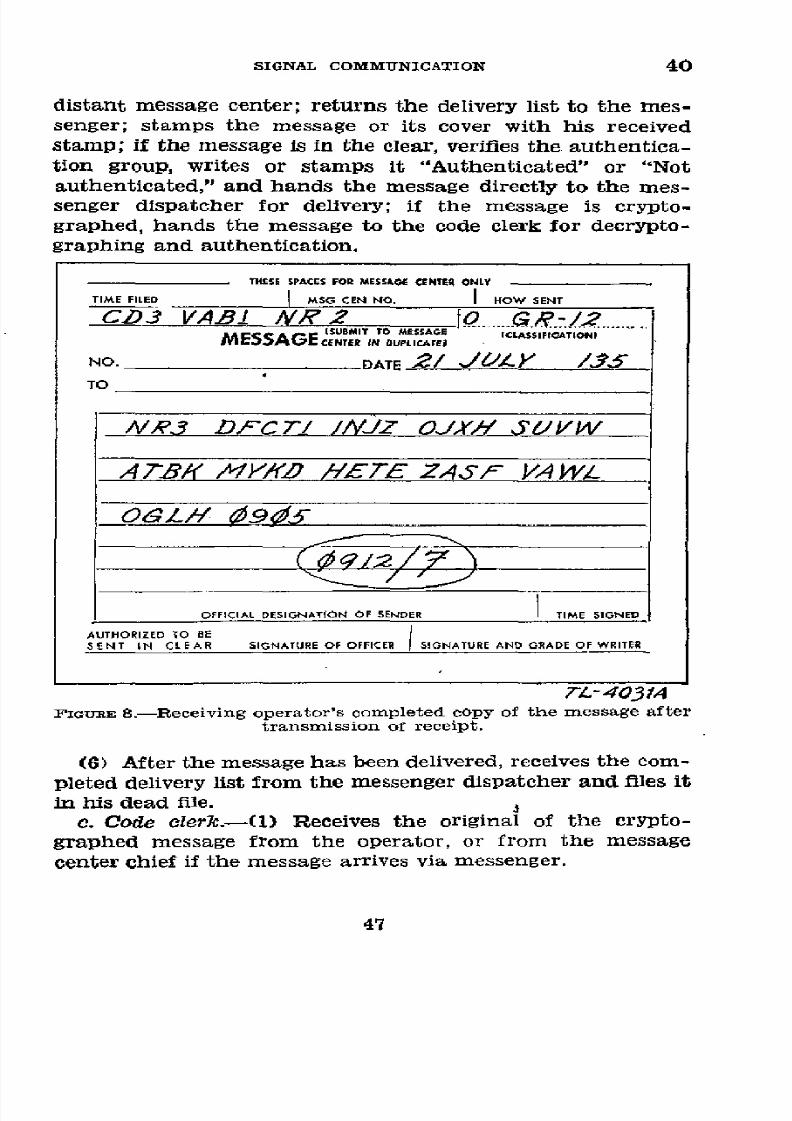
8/16/2019 (1942) FM 24-5 Signal Communication
http://slidepdf.com/reader/full/1942-fm-24-5-signal-communication 51/383
SIGNAL
COMMUNICATION
40
distant
message center;
returns
the delivery list to
the
mes-
senger; stamps the message or
its cover
with his
received
stamp;
if
the
message
is
in
the
clear,
verifies
the
authentica-
tion group, writes or
stamps it "Authenticated"
or
"Not
authenticated,"
and
hands the message
directly
to the mes-
senger
dispatcher
for
delivery;
if
the message
is
crypto-
graphed, hands the message
to
the code clerk for
decrypto-
graphing and authentication.
THESE PACESFORMESSAGE ENTER NLY
TIME FIlED
I
MSG CEN NO.
I
HOW
SENT
CD3
VA.B
NR2
O
0R..-....
ISUBMIT
TO MESSAGE
(CIASS.FITiIONI,
MESSAGECENTER IN DUPLICAOTE
NO.
DATE
2/
J,./
Y
/135
TO
/vR3 D/rCT/ //VJZ OJX, SVW
ATBK
1Y/XD -/7ETEASF
VA
WL
OFFICIAL
DESIGNATION OF SENDER TIME SIGNED
AUTHORIZEDO BE
SENT IN CLEAR
SIGNATUREOF OFFICER | SIGNATUREAND GRADE
OF WRITER
TL-4031A
FIGURE
8.-Receiving operator's
completed
copy
of
the message after
transmission
of receipt.
(6)
After
the
message
has
been delivered,
receives
the
com-
pleted delivery
list from the messenger
dispatcher and files
it
in
his dead
file.
c. Code
clerk.-(1)
Receives the original
of
the crypto-
graphed message
from
the
operator, or
from
the message
center
chief
if the message arrives
via messenger.
47

8/16/2019 (1942) FM 24-5 Signal Communication
http://slidepdf.com/reader/full/1942-fm-24-5-signal-communication 52/383
40 .
BASIC
FIELD
MANUAL
(2)
Verifies
the authenticity
of
the message
and writes or
stamps
the words "Authenticated"
or "Not
authenticated"
on'
the
face
of
the
clear
copy
of
the
message.
(3)
Deeryptographs
the
message,
making
an
original
only.
(4) Enters
the
offlcial
designations
of
the addressee
and
the sender,
as
determined
from
the
call signs
or from
the
designations
inclosed in
parentheses
and
the call signs
(see
par.
27b), the date,
time signed,
and
the operator's
heading
(if any)
or
the
distant
message center
data (if any)
in
their
proper
places
on the
decryptographed
copy of
the
message.
(See
fig.
9.)
(5)
Passes
the message
to
the
message
center
chief, files
the
original cryptographed
copy
of
the
message
in
his file for
reference,
and disposes
of this file
as
directed
by the
unit
signal or
communication
officer.
(6) Destroys
all work
sheets
by burning.
HINSE
PACES
Ot
MEISSAGEENTE
ONLY -
TIME
FIED
| MSG CEN NO.
HOW SENT
A.B/
/R
2
R ad
| ZNT..
SUBMIT
oIESSAGE
CLASSIFICATlONI
MESSAGECENTER
lN
DUPLICATEI
NO. 3 DATE 2/
-/¿-r
TO
CG /ST
C O R P S
c/VEIVy FORCCES
/AVE
CHIEC/hED
O¿/R
ADVANCAE
370P
REQU¿/EST
P/Ac9A
C
-
_=__-__
OF
SIGNED
AUTHORIZEDO BE
SENT IN
CLEAR
SIGNATURE OF OFFICER
SIGNATUREAND GRADEOFWRITER
TL-4032A
FIGoE~:
9.-Code
clerk's copy
of
the message
ready
for
delivery
to the
addressee.
48
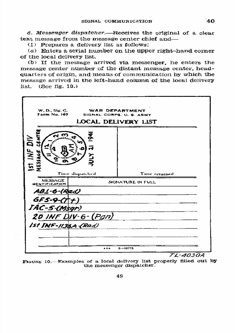
8/16/2019 (1942) FM 24-5 Signal Communication
http://slidepdf.com/reader/full/1942-fm-24-5-signal-communication 53/383
SIGNAL
COMMUNICATION
40
d.
Messenger
dispatcher.-Receives
the
original
of a
clear
text
message
from the
message
center
chief
and-
(1)
Prepares
a
delivery
list
as
follows:
(a)
Enters
a serial
number
on
the upper right-hand corner
of the
local
delivery list.
(b) If
the message
arrived
via messenger,
he enters the
message
center
number of the
distant
message center, head-
quarters of origin,
and means
of communication by which the
message arrived in the
left-hand
column of the local delivery
list.
(See
fig.
10.)
W. D., Sig. C. WAR
DEPARTMENT
Form No.
160
SIGNAL
CORPS.
U.
S ARMY
LOCAL DELIVERY
LIST
o
4-
>
Time di.pa.t h-d Time
returned
MESSAGE
IDMESSFICAGE SIGNATURE IN FULL
lDENTlFIATIC^
A46
-(A
____
6PS-9-
't)
20 /Nf¿ 1V-6-
(Pgn)
/st lMF-//.1 A 4Ra2
3-10775
TL-4030A
FIGURE 10.-Examples of a local delivery list properly filled
out
by
the
messenger
dispatcher.
49
8/16/2019 (1942) FM 24-5 Signal Communication
http://slidepdf.com/reader/full/1942-fm-24-5-signal-communication 54/383
40
BASIC
FIELD
MANUAL
(C)
If
the message
arrived
by
a
means requiring
an
opera-
tor,
he
enters the
headquarters
or station
of origin,
the
sta-
tion-to-station
serial
number
(if
the
message
is
in
the
nor-
mal
form)
or
the
time signed
(if the message
is
in
the
abbre-
viated form),
and
the
means of
communication
by
which
the
message
arrived
in
the
left-hand
column
of the
local
delivery
list.
(See
fig.
10.)
(2) Designates
a
messenger
to deliver the
message.
(3) Stamps
or
writes
the
time
dispatched
on
the
delivery
list when
the
messenger
is
ready to
depart. (See
fig. 10.)
(4)
Hands
the
message(s)
and
the
delivery
list to
the
mes-
senger and
gives him
the
necessary
additional
instructions
for
the
delivery
of
his message(s).
(5)
Stamps
or writes
the time
returned
in the
upper right-
hand
blank
of
the
delivery list
when
the
signed
delivery
list
is returned
to him
by the messenger.
(See
fig.
11.)
(6)
Hands
the completed
delivery
list
to
the
message cen-
ter
chief.
(7) In
handling
urgent
and priority
messages and in order
to
avoid delay
in
delivery,
the
messenger
may
be given
a blank
delivery
list
and be instructed
to request
the addressee
to
fill
in the message
identification
as
well
as
the signature,
and
in
case of
the
route
delivery
list, the
time
of
receipt.
e.
Messenger.-(1)
Receives
the
message
and
the
delivery
list
from
the messenger dispatcher.
(2)
Delivers
the
message
and
the
delivery
list
to
the
ad-
dressee
and
obtains his signature,
and in the
case of the
route
delivery
list,
the
time received.
(See
fig. 11.)
(3)
Returns
to
the message
center and
enters
his name,
initials,
or
his
messenger
number as
required
by
local regula-
tions, on
the delivery list
for
identification. (See fig. 11.)
(4)
Hands
the delivery
list to the messenger
dispatcher.
50
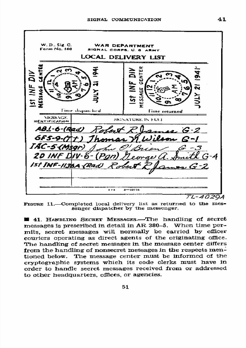
8/16/2019 (1942) FM 24-5 Signal Communication
http://slidepdf.com/reader/full/1942-fm-24-5-signal-communication 55/383
SIGNAL
COMMUNICATION
41
W.
D.. Sig.
C.
WAR DEPARTMENT
Form tNo.
160 lGSNAL
CORPS. U. B
ARMY
LOCAL DELIVERY
LIST
e
returned
1N
4
I
t
t.f;UE.
I
2
mw
,TL--29Ad
E IG1E
ll.--ompleted
loca delivery
lt
as
retumned
to
the
mes-
\IESSAG
Z4C 5<A~
r); I•/•j-Z
-
senger
dispatcher
by
the
messenger.
* 41. HANDLING
SECRET MESSAGES.-The
handling
of secret
messages is prescribed
in detail in
AR 380-5.
When time
per-
mits, secret
messages
will
normally
be
carried
by
officer
couriers operating
as direct
agents
of the
originating
office.
The handling of secret messages
in the
message
center differs
from
the
handling
of nonsecret
messages
in
the respects
men-
tioned below.
The message
center must be informed of the
cryptographic systems
which its code
clerks must
have
in
order
to handle secret
messages
received
from
or
addressed
to
other headquarters,
offices,
or
agencies.
51

8/16/2019 (1942) FM 24-5 Signal Communication
http://slidepdf.com/reader/full/1942-fm-24-5-signal-communication 56/383
41-42
BASIC
FIELD
MANUAL
a.
Outgoing messages.-The
writer of an outgoing
message
submits
only the
original
copy of a
secret
message
to
the mes-
sage
center.
The
message
center
chief
stamps
this
message
with his
time
stamp and serial number
stamp,
makes the
notation
"Secret"
in the "Remarks"
column of
his
number
sheet,
and passes the
message
to the
code
clerk.
The
code
clerk
mdkes
an
original and
a skeleton copy
of the
crypto-
graphed
message, these copies being henceforth
handled
in
the same manner as nonsecret messages.
The original of the
plain text message
is
then marked, "Sent (date)"
and
is im-
mediately
returned
to
the
originator's
office
for
file.
The
original
of the
cryptographed
message
is passed to the trans-
mitting
agency,
the
skeleton
copy is placed
in
the live
file,
and
final
disposition
made in
the
same
manner
as for
skeleton
copies of nonsecret
messages.
b. Incoming messages.-An
incoming secret message is han-
dled in the same manner
as
a
nonsecret
message
except that
the
single copy
of
the plain text is
marked
by
the code clerk
"Secret."
* 42.
HANDLING
RELAY
MESSAGES.---a.
The
operator
hands or
sends both the original
and
the duplicate copy to the mes-
sage center chief whether received cryptographed
or
in
clear.
If
the
message
is
received from
a messenger,
only
the
original
is available.
b.
The message
is
then
handled
as
an
outgoing
message.
It
is
not
given
a
message
number
by
the relaying
message
center.
c.
A
message
received in
secret
text is
not
decryptographed
by
the relaying
message center.
d.
A copy
of
the
message will
be
available
in
the message
center with
the operator's service
for
follow-up
if
receivéd
or transmitted
by
electrical
means.
e.
No
copy
of
the
message
will
be
available
in
the
message
center
if received
and
transmitted
by messenger.
In
this
case, the signed
delivery list or
message
envelope is the
only
record.
If considered
necessary,
a
skeleton
copy may
be
made for
reference.
52

8/16/2019 (1942) FM 24-5 Signal Communication
http://slidepdf.com/reader/full/1942-fm-24-5-signal-communication 57/383
SIGNAL
COMMUNICATION
43-46
SECTION III
PROCEDURE IN HEADQUARTERS BELOW DIVISION
U
43.
GENERAL.-Simplicity
and
speed
in handling
message
traffic are paramount considerations. If necessary to meet
local
requirements,
unit commanders are authorized to make
modifications
in
the
procedure given in paragraph 47.
*
44. ORGANIZATION.-a. In
describing the
procedure, duties
are
outlined
for
message
center chief, messenger dispatcher,
code clerk, messenger, and operators of the several
means of
signal communication.
This
division
of duties is
funetional
and
is made
for convenience
in description.
For
definitions
of the terms
"message center chief" and
"operator",
see
para-
graph 36. For
the
classification
of
messages,
see paragraph
19.
b.
In
small message
centers
during slack
periods, one
man
may perform all the duties. Por this reason each member
of
the
message
center team
must
be
trained
to perform
all
the
duties
incident to message center operation.
The
per-
sonnel should
be able to operate as
more
than one team
in
order
to
provide for continuous
operation when
the command
post
is
moved.
c.
Radio
operators are authorized
to cryptograph
and
de-
cryptograph messages
when
their radio station is separated
from
their
message
center
by an
appreciable
distance
or
there
is
no message
center.
(See
par.
49b.)
0 45.
FORMS
AND
EQUIPMENT.-Message center
procedure
is
not dependent
on
forms.
No equipment
other than pencil,
paper,
timepiece,
and the
authorized
codes
and cipher
devices
is
required. Certain
forms
such as delivery
lists, number
sheets, field
message
books, and message
envelopes are,
how-
ever,
usually provided
for convenience and
to save
labor.
(See
par.
37.)
*
46.
RECORDs.-The
message center keeps only
such
tem-
porary
records
as are
required
to insure rapid
and
accurate
handling of
message
traffic. The following
records are
usu-
ally
kept:
a. Number
sheet.-Message
center
numbers are
assigned
to
each outgoing
message.
(See par.
39a
(4).)
If desirable,
53

8/16/2019 (1942) FM 24-5 Signal Communication
http://slidepdf.com/reader/full/1942-fm-24-5-signal-communication 58/383
46
BASIC FIELD
MANUAL
the chart
referred
to
in
paragraph 34c and the
number
sheet
referred
to in paragraph 37d may
be
combined into
a
message
center
log.
An
example
of
an
extract
of
such
a
log
is
shown
below. Spaces
for 100
numbers
and
additional
units
may
be
conveniently
provided on
the form.
If
it is used,
the
instruc-
tions
in
this chapter
dealing
with the number
sheet apply
also
to
this form.
MESSAGE CENTER 'LOG
lst
FA
Bn
9-6-41
(Unit)
(Date)
Record
of
serviceability of means
Units
to RAD TG
TP No. mars
No. Remarks
which con-
nected
In Out In
Out
In
Out
645A 705A 715A 830A 705A 830A I
Rad
51
830A 845A 845A 930A
845A 930A Y Tg 52
6th
Div 930A 1000A 1000A '_--
1000A
----- 2
Msgr
53
Arty -
Msgr
54
-......................................- Msgr
55
...............................6 .....--
6
...............................
7
.------
57
, .......... ...........-... -..- --.
8
"--.. ._58
.......................................-~
9
-------
5
9
b.
Receipt form.-The receipt form may be a
delivery
list,
message envelope, message blank, or blank sheet
of paper.
If
an acknowledgment
has been
requested
by
the
writer,
nota-
tion of this
fact
will
be made on the receipt
form.
(See par.
38c.)
c.
Live file.-The
live file
consists
of a
duplicate
or skeleton
copy
of
each
outgoing message
which has been
sent to
a
signal agency for transmission but for which
a
receipt
has
not yet been
obtained.
d.
Dead
ftle.-The
dead file
consists
of
the duplicate or
skeleton
copies of
all receipted outgoing
messages;
completed
54

8/16/2019 (1942) FM 24-5 Signal Communication
http://slidepdf.com/reader/full/1942-fm-24-5-signal-communication 59/383
SIGNAL
COMMUNICATION
46-47
receipt forms; and the receipted duplicate
clear text
copies
of
all
incoming messages received
by means other than special
messenger.
The
dead
file
is disposed
of
daily
or
oftener
as
directed by
the unit communication
officer.
Unless
other-
wise directed by the commander, it
is
turned over
to
S-1 at
frequent intervals
so that
messages may be included
in
the
unit
journal. (See
par.
257.)
e.
Code
clerk's
file.-This file
contains
the
original clear
copy
of
all outgoing
messages
sent as cryptograms
and the
original
copies
of
all
incoming
cryptographed
messages.
Caution: Clear
and
cryptographed copies
of
the same mes-
sage must
never be
filed
together.
The file
is disposed
of
daily as
directed
by
the,unit communication
officer.
(See
par.
257d.)
* 47.
HANDLING
MESSAGES
(see par.
21c).-The
following
pro-
cedure is
one
of several methods which may be used in
handling messages
at a message center.
It should
be
re-
membered
that the assignment
of
duties as tabulated
below
is
functional and that one
man
may
perform
several or all
func-
tions in
a certain message
center,
whereas
one or
more
men
may be
necessary
to perform a single function in another.
a. Message
center chief.-(1)
Outgoing
messages.-(a)
Receives
message in duplicate from
writer.
(See
fig.
1.)
(b) Makes skeleton copy when single
copy
or bundle
of
maps
is
submitted
to
message
center.
(c)
Writes
or
stamps
on front
or
back
of both
copies-
1.
Time
filed.
2. Message center
number.
3. How
sent. (See
fig. 2.)
(d) Checks message
center number
off number sheet by
drawing
diagonal
line
through corresponding
number.
(See
fig.
3.)
(e)
Notes briefly,
opposite
the assigned
number and
in re-
marks
column
of number
sheet,
data
which he
considers
necessary
for reference.
(See
fig.
3.)
Examples:
1. Writer's designation.
2. Addressee.
3. Method of transmission (Rad, Tg,
etc.).
4. Precedence.
55
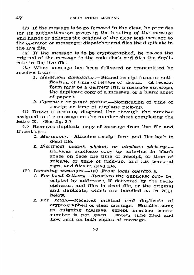
8/16/2019 (1942) FM 24-5 Signal Communication
http://slidepdf.com/reader/full/1942-fm-24-5-signal-communication 60/383
47
BASIC
FIELD
MANUAL
(f)
If
the message
is
to go forward
in
the
clear,
he
provides
for its authentication
group in
the
heading
of the message
and hands
or delivers
the
original
of
the
clear
text
message
to
the
operator
or messenger
dispatcher
and files
the
duplicate in
the
live
file.
(g) If
the message
is to
be
cryptographed,
he passes
the
original
of the message
to
the code
clerk
and files
the dupli-
cate
in
the
live file.
(h)
When
message
has
been
delivered
or
transmitted
he
receives
from-
1. iessenger
dispatcher.-Signed
receipt
form
or noti-
fication of
time
of
release
of pigeon.
(A receipt
form
may
be
a delivery
list,
a message
envelope,
the
duplicate
copy
of a message,
or
a blank
sheet
of
paper.)
2. Operator
or
panel
station.-Notification
of time
of
receipt
or
time
of airplane
pick-up.
(i)
Draws
a
crossing diagonal
line
through the number
assigned
to
the message
on
the number
sheet
completing
the
letter
X.
(See
fig. 3.)
(j) Removes
duplicate
copy
of message
from live
file and
if
sent by-
1.
Messenger.-Attaches
receipt
form
and
files
both
in
dead
file.
2. Electrical
means,
pigeon,
or
airplane
pick-up.-
Services
duplicate
copy
by
entering
in blank
space
on face
the time
of
receipt,
or
time
of
release,
or time
of
pick-up, and
his
personal
sign,
and
files in dead
file.
(2)
Incoming
messages.-(a)
From
local
operators.
1.
For
local
delivery.-Receives
the
duplicate
copy
re-
ceipted
by addressee,
if delivered
by
the
radio
operator, and
files
in
dead
file,
or
the
original
and duplicate,
which
are
handled
as in b(1)
below.
2. For
relay.-Receives
original
and
duplicate
of
cryptographed
or clear
message.
Hlandles
same
as outgoing
message,
except
message
center
number
is not
given. Enters
time filed
and
how sent
on
both
copies
of message.
56
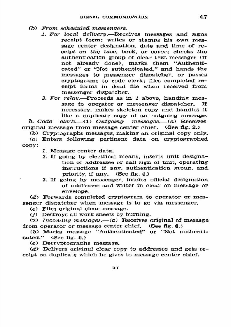
8/16/2019 (1942) FM 24-5 Signal Communication
http://slidepdf.com/reader/full/1942-fm-24-5-signal-communication 61/383
SIGNAL
COMMUNICATION 47
(b) From scheduled
messengers.
1. For
local
delivery.-Receives messages
and signs
receipt form;
writes or
stamps his own mes-
sage
center
designation,
date
and
time
of
re-
cept on the face, back,
or cover; checks
the
authentication group of
clear text
messages (if
not already done), marks them "Authenti-
cated"
or
"Not
authenticated,"
and hands
the
messages to messenger
dispatcher, or
passes
cryptograms
to
code clerk;
files completed
re-
ceipt
forms
in
dead
file
when
received
from
messenger dispatcher.
2.
For relay.-Proceedsas
in 1 above,
handing
mes-
sage
to operator
or messenger
dispatcher.
If
necessary, makes
skeleton
copy
and handles it
like
a duplicate
copy of an outgoing message.
b.
Code
clerk.-(1)
Outgoing
messages.-(a)
Receives
original message from
message
center chief.
(See
fig. 2.)
(b)
Cryptographs
messages,
making
an
original
copy
only.
(c) Enters
following
pertinent
data on cryptographed
copy:
1.
Message center
data.
2. If going by electrical
means,
inserts unit designa-
tion of addressee or call sign of unit, operating
instructions
if
any,
authentication group,
and
priority, if
any. (See fig. 4.)
3.
If
going
by
messenger,
inserts
official
designation
of addressee
and
writer
in clear
on message or
envelope.
(d) Forwards
completed
cryptogram
to operator or mes-
senger dispatcher when message is
to
go via messenger.
(e) Files original clear message.
(f) Destroys all work sheets by burning.
(2)
Incoming
messages.-(a)
Receives
original
of message
from
operator
or
message center
chief. (See fig.
8.)
(b) Marks
message "Authenticated" or
"Not authenti-
cated." (See
fig.
9.)
(c) Decryptographs
message.
(d) Delivers original clear copy to addressee
and
gets re-
ceipt on
duplicate
which he gives to
message center
chief.
57

8/16/2019 (1942) FM 24-5 Signal Communication
http://slidepdf.com/reader/full/1942-fm-24-5-signal-communication 62/383
47
BASIC
FIELD MI'ANtAL
(e) Destroys
all work sheets
by
burning.
c. Operator.-(1)
Outgoing
messages-(a)
Receives
the
original
message
from-
1.
Message
center
chief if clear
text.
2.
Code
clerk
if
cryptographed.
(b)
Transmits
message.
(c)
Obtains
receipt.
(d)
Services
message.
(e)
Notifies
message
center
chief of
time
of receipt
and
files
message.
(2)
Incoming
messages.-(a)
Copies
message
in
duplicate.
(b) Services
message.
(c)
If message
is
in
clear,
passes
it in
duplicate
to the
message
center chief
who receipts
.on
the
duplicate.
Local
commander
may
require
that he deliver
the
original
in
clear
to
the addressee
when
nearby,
and obtain
his
receipt
on the
duplicate.
Files
receipted
duplicate.
(d) If
message
is
cryptographed,
hands
original
to
code
clerk
and
files
duplicate.
d.
Messenger
dispatcher.-(1)
Outgoing
messages.-(a)
Receives
original
message
from-
1. Message center
chief
if
clear
text.
2.
Code
clerk
if cryptographed.
(b) Special
messenger service-
1.
Prepares
receipt
form by
entering
message
identifi-
cation
and time dispatched thereon.
(See
fig.
12 which
illustrates
message
envelope
as
receipt
form.)
2. Hands
message
and
receipt
form
to
messenger
and
gives
him
any necessary
instructions concern-
ing
the delivery.
(c)
Scheduled
messenger service-
1.
Enters
on
receipt
form
the
message identification
as
each
message
is
received.
2.
At time
scheduled
for
next
messenger's
departure,
writes
or stamps the
time
dispatched
on the
receipt
form
and hands
message
and
receipt
form to
messenger.
(d) If message
is
to go
by pigeon,
he
places message
in
miessage
holder, releases
bird,
and
notifies message
center
chief of time of
release.
58

8/16/2019 (1942) FM 24-5 Signal Communication
http://slidepdf.com/reader/full/1942-fm-24-5-signal-communication 63/383
SIGNAL COMMUNICATION
47
MiElo . M-40
¿/4RGENT
MESSAGE
TO
CO /SZ Af
NO. 3
FUI
. thLeolloin.g nd
obtain roeIpt if d.elvey
Iit NOT
.us.
TMDO I S P A T C H E O
74L
TIME RETURINEO_
RECEIVED
TIME
rT-4033A
FIGURE
12.-Message
envelope
properly
filled out
by messenger
dispatcher.
(e)
If message
is
to
go
by
airplane
pick-up,
he
sends
mes-
sage to panel
station,
which notifies
message
center
chief
of
time
of
pick-up.
(f)
Enters time
returned
on
signed
receipt form
when it
is
returned
by special
or scheduled
messenger.
(See fig.
13
Mwi
Eado.
M-40
R0GENT
MESSAGE
(CLM~caaa.
Rloa ovo nL.)
TO
CO
/IS7
'/IV
NO.
3
(Rcpflíthsafo
s
c
w c~ eQ ,d0
li~oai>
(O.zr
iSooidoo
Fill
i. th following and
obtain
r-ceipt if de.ier1y ist is NOT
-ued.
TIM£ DISPATCHED
T7w
1
rME RFTURjNED
M 0 9 3
RECEIVED
____
_______
TIME
7 -M57
7L
4034A
FIGURE
13.-Message
envelope
properly
completed when used as
a
receipt
form.
59
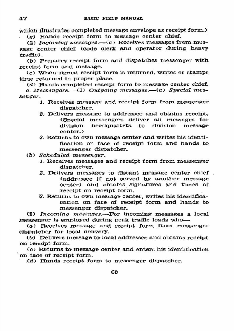
8/16/2019 (1942) FM 24-5 Signal Communication
http://slidepdf.com/reader/full/1942-fm-24-5-signal-communication 64/383
47
BASIC FIELD
MANUAL
which
illustrates
completed
message
envelope as receipt
form.)
(g)
Hands receipt
form to message
center
chief.
(2)
Incoming
messages.-(a)
Receives
messages
from
mes-
sage
center chief
(code
clerk
and operator
during
heavy
traffic).
(b)
Prepares
receipt
form and
dispatches
messenger
with
receipt form
and
message.
(c)
When
signed receipt
form
is
returned,
writes
or
stamps
time
returned
in
proper
place.
(d) Hands
completed receipt
form to
message center
chief.
e.
Messengers.-(1)
Outgoing
messages.-(a)
Special mes-
senger.
1.
Receives
message
and receipt form
from
messenger
dispatcher.
2. Delivers
message
to addressee
and
obtains
receipt.
(Special
messengers
deliver
all
messages for
division
headquarters
to
division
message
center.)
3.
Returns
to
own
message
center and
writes
his
identi-
fication
on face of receipt form
and
hands
to
messenger
dispatcher.
(b)
Scheduled
messenger.
1.
Receives
messages and receipt
form from
messenger
dispatcher.
2. Delivers
messages
to distant
message
center
chief
(addressee
if
not
served
by
another
message
center)
and
obtains
signatures
and
times
of
receipt
on receipt
form.
3. Returns
to own message center,
writes his identifica-
cation
on face
of
receipt form
and
hands to
messenger
dispatcher.
(2)
Incoming
messages.-For
incoming
messages
a
local
messenger
is employed
during peak traffic
loads
who-
(a)
Receives
message
and
receipt
form from
messenger
dispatcher
for
local
delivery.
(b)
Delivers message to local addressee
and obtains receipt
on receipt
form.
(c) Returns to message
center and enters his identification
on
face
of
receipt form.
,(d)
Hands
receipt
form
to
messenger
dispatcher.
60
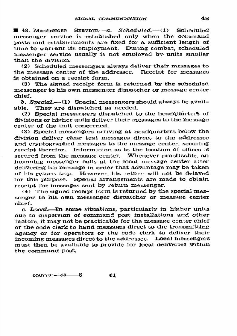
8/16/2019 (1942) FM 24-5 Signal Communication
http://slidepdf.com/reader/full/1942-fm-24-5-signal-communication 65/383
SIGNAL
COMMUNICATION
48
* 48. MESSENGER
SERVICE.---. Scheduled.-(1)
Scheduled
messenger
service
is
established
only when the command
posts
and
establishments
are
fixed
for
a
sufficient
length
of
time to
warrant
its
employment.
During combat,
scheduled
messenger service usually
is not
employed by units
smaller
than
the division.
(2) Scheduled
messengers
always
deliver
their
messages
to
the
message center of
the
addressee. Receipt
for messages
is
obtained on
a receipt
form.
(3)
The
signed
receipt
form
is returned
by
the scheduled
messenger
to his
own
messenger
dispatcher
or
message
center
chief.
b.
Special.-(1) Special
messengers
should
always be avail-
able. They
are dispatched as needed.
(2)
Special
messengers
dispatched
to the
headquarter%
of
divisions or higher
units
deliver
their
messages to the message
center
of the unit concerned.
(3)
Special messengers
arriving
at
headquarters
below
the
division deliver
clear text messages
direct
to the
addressee
and cryptographed
messages
to the
message center,
securing
receipt
therefor.
Information
as
to the
location of offices
is
secured from
the
message center.
Whenever
practicable,
an
incoming
messenger calls at
the local
message
center
after
delivering
his message
in
order
that
advantage
may
be taken
of his
return
trip.
However, his
return
will
not be delayed
for this
purpose.
Special
arrangements
are made
to
obtain
receipt
for
messages sent by
return
messenger.
(4)
The signed receipt
form
is returned by
the
special
mes-
senger
to
his
own
messenger
dispatcher or
message center
chief.
c.
Local.-In some
situations,
particularly
in higher units
due
to dispersion
of command
post
installations
and
other
factors,
it
may
not
be
practicable
for
the
message
center
chief
or the
code
clerk to hand
messages direct
to the
transmitting
agency
or for operators
or
the code clerk
to deliver
their
incoming messages
direct to the
addressee. Local
messengers
must
then be available
to provide for
local
deliveries within
the command
post.
656773°-43-5
61
8/16/2019 (1942) FM 24-5 Signal Communication
http://slidepdf.com/reader/full/1942-fm-24-5-signal-communication 66/383
49-50
BASIC
FIELD
MANUAL
SECTION
IV
MILITARY
CRYPTOGRAPHY
U
49.
Usr
oF
CRYPTOGRAMS.--.
In
time
of
war
or
national
emergency,
all
messages
to be
transmitted
by radio
or
by
other
means
when
danger
of hostile
or unauthorized
interception
exists,
are
cryptographed
and,
if necessary,
authenticated,
except
that-
(1) When
the tactical
situation
is
such
that
time
cannot
be spared
for cryptographing
and
when
the information
to
be transmitted,
if
intercepted
by
the enemy,
cannot
be acted
upon
in
time
to influence
the situation, the
commanding
officer
or
his
authorized
representative
may order
the
trans-
mission of
messages
in
plain language.
Written
messages
will
be marked,
"Send
in
clear," over
the signature
of
the
commander
or
his
authorized
representative.
Responsibility
for transmissions
by
radiotelephony
in the
clear
rests
with
the
offlcer
in
charge
of
the
transmitting
station.
When writ-
ten
or oral
messages
in
the
clear are authorized,
the
maxi-
mum
care must be
taken to
avoid
disclosing
the
contents
of
future
plans or
locations
of
friendly
troops
and installations.
The use
of
prearranged
messages
in the
elear
will
expedite
transmission.
(2)
Commanders
of units
smaller than
a division
may au-
thorize
the
normal
transmission
of
messages
in clear
text
which are
to
be
acted
upon immediately
in
rapidly
moving
situations.
(3)
Transmission
of
artillery
fire-control
messages
is in
clear.
(Fire-control
code
is
considered
clear
text.)
b. All
cryptographing
and
decryptographing
of messages
at
a
headquarters
are
performed
in
the message
center,
ex-
cept
as authorized
in
paragraph
44,
unless
the message
re-
quires
a
code or
cipher not
in
the
possession
of
the
message
center.
The
message
center
is
provided
with
the
authorized
codes,
cipher
devices,
and
keys.
c.
If
it becomes
necessary
to
modify
the
wording
of a
mes-
sage
to
facilitate
eryptographing,
the
modified
text
should
be
submitted
to
the
writer
before
eryptographing.
U
50.
DEFINITIONS.-A
knowledge
of the
following
terms
is
essential
for all
personnel
handling
code
and
cipher
mes-
sages:
62
8/16/2019 (1942) FM 24-5 Signal Communication
http://slidepdf.com/reader/full/1942-fm-24-5-signal-communication 67/383
SIGINAL COMMUNICATION
50
a. "Plain
text", "clear
text",
or
"plain
language" is
the text
of a
message
which, on
its
face,
conveys
an
intelligible
mean-
ing
in a
spoken language.
b.
"Secret
text"
or
"secret language"
is
the
text
of
a
mes-
sage which,
on
its
face, conveys
no intelligible
meaning
in
any spoken
language.
The
secret
text of
a message
consti-
tutes
a
cryptogram.
c. "Cryptography"
is the
science
which
treats
of the
various
means, methods,
and
devices
for
converting
plain-text
mes-
sages
into
cryptograms and
reconverting
the so-produced
cryptograms
into
their plain-text
forms
by
a
direct
reversal
of the steps
or processes
employed
in
the
original
conversion.
d.
"Cryptograms"
are
of
three types as
follows:
'(1)
Cipher.-A
cryptogram
in
cipher is one
which has
been
produced
by taking
the individual
letters of
the
plain
text as units
and
applying
to
them
either or
both of
two
cryptographic processes
known
as
"transposition"
and "sub-
stitution"
explained below.
The resulting
secret text
is
called
"cipher
text"
and
the
operation
of
producing
it
is
called
"enciphering"; the reverse
operation,
that
of
reproducing
the
plain text
from the cipher
text
by
a direct reversal
of the
steps
involved
in
its
enciphering,
is called
"deciphering."
The basis
of every
cipher system
is an agreement
between
correspondents
covering
the
general
method
and
the
steps
to
be followed
in cryptographing.
That part of
the agreement
which
specifically
controls the
steps under
the general
method
is
termed
the
"key."
The
key
is
usually
of
a
variable
nature,
changeable
at
the
will
of the correspondents.
Normally
it
consists of
an
easily
remembered
word,
phrase,
or sentence;
or of a number
or series
of
numbers
derivable
from
a
word,
phrase,
or sentence.
In signal
communication,
keys
are
changed
in accordance
with
signal
operation
instructions.
(a) Transposition
cipher.-The
cryptographic
process
known
as
transposition
consists
in
rearranging
the
letters
(rarely
syllables
or whole
words)
constituting
the plain
text
so
that
the
resultant
text becomes
unintelligible.
The
letters
undergo
no change in
identity; only
their relative
order is
altered.
A cryptogram
which
has
been
produced
in this
way
is
termed a "transPosition
cipher."
63
8/16/2019 (1942) FM 24-5 Signal Communication
http://slidepdf.com/reader/full/1942-fm-24-5-signal-communication 68/383
50
BASIC FIELD MANUAL
(b) Substitution cipher.-The cryptographic process
known
as
substitution consists
in
replacing the letters constituting
plain
text
by
other
letters,
figures, symbols, etc.
Here
the
letters undergo a change in
identity without
a change in their
relative
order. A cryptogram which has been produced in
this
way is termed
a "substitution cipher."
(c)
Combined cipher.-When
both
of these
processes
have
been applied in producing a cryptogram, the latter
is
termed
a
combined
"substitution-transposition
cipher."
(2) Code.-(a) A cryptogram
in
code
is one which has
been
produced
by
taking
whole
sentences,
phrases,
words,
letters, or numbers of plain text as units and
replacing
them
by arbitrary groups
of symbols
given
as their equivalents in
a
code
book. The
resulting secret text is called "code text"
and
the operation
of
producing it
is called
"encoding"; the
reverse operation, that of reproducing the plain text from
the
code text by
reference
to the
code
book, is called "de-
coding."
A
one-part
code
consists
of
an
alphabetical list
of
code groups
with a
corresponding
alphabetical
list
of
equiva-
lent meanings.
This one section
serves both for
encoding
and
decoding messages. A two-part code consists of
two
sections;
an encoding section and a decoding section.
The
encoding section comprises an
alphabetical list
of
meanings
set
opposite
random
code groups.
The decoding section com-
prises
an
alphabetical
list
of code groups with their equiva-
lent
meanings set
opposite
them.
Since
the
one-part
code
lists
both the code groups and the equivalent
meanings
alpha-
betically, a cryptanalyst is enabled to confine his search
for
the
proper
equivalent word to words whose initial letter
oc-
curs in
a
small
section of
the alphabet,
whereas
any
word
might be the equivalent meaning of a code group
in
a two-
part code. As a consequence, the two-part code is
much
more
secure than the one-part
code.
(b)
Code
groups
or
code
words
are
arbitrary
groups
of
symbols constituting code text.
They
usually consist of let-
ters or
figures,
rarely of both.
(3) Enciphered code.-A
crytogram
in
enciphered code is
one
vhich
has been
produced by
first
encoding
the
plain
text
and
then enc4phering the
code text.
e. To "cryptograph"
a
message is to convert its plain text
lnto
secret
text.
This
is
a
convenient term to
use
in re-
64

8/16/2019 (1942) FM 24-5 Signal Communication
http://slidepdf.com/reader/full/1942-fm-24-5-signal-communication 69/383
SIGNAL
CÓ)MMUNICATION 50-52
ferring
to the processes
involved
without indicating
or specify-
ing whether they
are methods
of
enciphering or
encoding.
/.
To
"decryptograph"
a
message
is
to
reconvert its
secret
text
into plain
text
by
a direct
reversal
of the
operations
in-
volved
in
its
cryptographing.
This
is
a convenient
term
to
use
in
referring to
the processes involved
without indicating
whether
the
cryptogram
is in
cipher,
in
code, or
in enciphered
code.
As
enciphering
and
encoding
are forms
of crypto-
graphing, so
deciphering
and decoding
are forms
of decrypto-
graphing.
g.
"Cryptanalysis"
is
the
name applied
to
the
steps
and
processes
involved
in
converting
cryptograms
(usually
of hos-
tile origin)
into plain
text by
means
other
than those
nor-
mally
employed
in decryptographing
messages
of
friendly
origin.
*
51.
SAFETY
AFFORDED
BY CRYPTOGRAPHY.-Codes
and ciphers
are
used to condense
messages
or
to
maintain
the
contents
secret,
except
from
the
addressee, or
for
both
purposes.
Unless
secrecy
is
reasonably
certain, all additional
time,
labor,
and danger
of
error
involved in
cryptographic
messages
is
wasted;
moreover,
the
correspondents
may
be lulled
into
a
false
sense of security
in the belief that
their messages
are
secret, when,
in fact,
the
enemy may
have cryptanalyzed
them
and
taken
action
accordingly.
With
the
use of radio
as
well as
other
means
of electrical
communication,
the safe-
guarding
of
codes
and
ciphers
has
assumed
a
paramount
importance.
No
cyptographic
system
suitable
for a
volumi-
nous official
correspondence
is
absolute
proof against the
organized,
cooperative
efforts
of
a
large
and
well-trained
staff of
cryptanalysts.
Practically
every cipher
system
that
has ever
been employed
for
military
purposes
has
been solved
and
practically
any
code
book can
be
reconstructed
by
analysis,
given a
sufficient
number
of
cryptograms
and
the
personnel
and
time necessary
to accomplish
it.
·
52. COMPARISON
OF
CODES
AND CIPHERS.--.
Both
code and
cipher methods
are needed
in the
military
service.
The
prin-
cipal
factors
to
be considered
in comparing
them
are-
(1) Simplicity,
rapidity,
practicability.
(2) Secrecy.
(3) AccuracY.
(4)
EconomY.
65
8/16/2019 (1942) FM 24-5 Signal Communication
http://slidepdf.com/reader/full/1942-fm-24-5-signal-communication 70/383
52-53
BASIC
FIELD
MANUAL
b.
In
general,
code is
a more
rapid
and
more
simple
method
of
secret
communication
than
is
cipher.
The
processes
of
enciphering and
deciphering
require very
close
mental
atten-
tion
to avoid
errors, and are
usually much
slower
than
those
of encoding
and
decoding,
which
are more
nearly
automatic.
This is
of greatest
importance
in
the
combat
zone.
There
are
some very
small
cipher
devices
which
tend
to reduce
the
mental
strain to a
minimum,
but
usually
the
cryptograms
they yield
are
not
as secret
as
those
produced
by
a good code,
especially
when
many
messages
are
available
for enemy
inter-
ception.
c.
Code systems
are, on
the
whole,
more secret
than
cipher
systems,
depending
upon
the
type
of
code, the
extent
of its
vocabulary
or
contents,
and
the extent
to
which
it
is
used;
that
is,
the number
of
messages
transmitted.
Furthermore,
the
solution
of one message
as a rule
does
not
entail
the
im-
mediate
break-down
of
the
whole
system,
with
the
consequent
solution
of all
other
messages
in
the
same
key,
as
it
does
in
ciphers.
However,
it is
necessary
at
all
times to
guard the
code
book
so that it
does
not
fall
into
the hands
of the
enemy.
Actual possession
is
not always
necessary,
for
a single
oppor-
tunity
to copy
or
memorize
certain
parts
is sufficient
to com-
promise
the
whole
code.
d. Code
systems,
on
the
whole,
are
less
accurate
than
cipher
systems
and
are more
subject
to the
necessity
for
repetition
of
messages, because
a
mistake
in
one
or
two
code
groups
may
obscure,
alter,
or render
unintelligible
the
mean-
ing
of a
whole
message,
whereas
the
meaning
of a few
letters
which
are
in error
in
cipher
may be
supplied
by the
context.
e.
Code text
is usually shorter
than
the equivalent
plain
text.
Codes of
the two-part
type
must
be changed
rather
fre-
quently
to
maintain
secrecy.
This necessitates
repeated
proc-
esses-of
preparation,
printing,
and
distribution,
all
of which
take
much
time
and
labor.
E
53.
AUTHORIZED
MILITARY
CODES
AND
CIPHERS.---a.
Codes.-
The
authorized
codes
when
issued
are
accompanied
with
detailed
instructions.
The
codes
vary
in
type
and
composition
cn

8/16/2019 (1942) FM 24-5 Signal Communication
http://slidepdf.com/reader/full/1942-fm-24-5-signal-communication 71/383
SIGNAL
COMMUNICATION
53
to fit
the specific requirements.
See AR
380-5
for
the
manner
in which codes
are authorized to
be used.
b.
Special
codes.-Such
codes
as
address
and
signature
codes,
map coordinate
codes, geographic,
meteorological,
and
supply
catalog
codes,
as well
as appendixes
to the
various
codes
mentioned
in
a above,
may
be
published from time
to time.
c. Prearranged
message
codes.-To
reduce the
time
re-
quired
for cryptographing
and transmission
in
tactical situa-
tions, a single code group, the meaning of
which
will not be
readily
apparent
to
the
enemy,
may
be
used
to
conIvey
a
short
complete tactical
message.
A listing of such code groups,
together
with
their
meanings,
may be
prepared
in
advance
of
tactical
operations
by unit commanders, and is
called
a
pre-
arranged
message
code.
Security from eneiny
knowledge
is
based on frequent changes of the messages or
in the assign-
ment
of code
groups for the messages.
The
following
is
an
example
of
the
type
of
material
suitable
for
a
prearranged
message
code:
Code group
Meaning
Tg
Tp
AB AFIRB BAKER Combat
team
82 now at-.
LO
LOVE OPTION
Division CP now at GETTYSBURG.
Employment
of
the 2-letter groups will
give
a
possibility
of
676 different combinations.
Generally a
limited
number
of
groups
will
be
required,
and the
selections
of
2-letter
groups
having
the
greatest
phonetic
difference
when
transmitted
in
the international
Morse
alphabet should
be
used.
The use of
th.e
authorized
phonetic alphabet
for
telephone
or radiotele-
phone
transmissions insures phonetic
differences.
Short,
dis-
tinctive
words
also
may
be used as
the
code
groups,
care
being taken to avoid
having
two or more
words of
similar
phonetic content.
Where the
signal
officer
feels that
mes-
sages sent
in the prearranged
message
code
may
be
confused
with
messages
in
other
codes,
an
indicator group
may be
assigned
for use with the prearranged message code.
d. Ciphers.-Among
others,
the
cipher
device
M-94
and
converter M-209 are authorized for use in
the
military service
(see
secs.
V
and
VI).
e.
Indicators.-(1)
A
partial
list
of
the
various message
67

8/16/2019 (1942) FM 24-5 Signal Communication
http://slidepdf.com/reader/full/1942-fm-24-5-signal-communication 72/383
53-54
BASIC
FIELD
MANUAL
codes
and
ciphers
with
their
indicators
and
the
number of
characters
comprising
each
group
is
shown
below.
Indicators
of
codes
authorized
for
training
include
the
letter T
before
the
number.
For example,
DFCT2
is
the indicator
for
Train-
ing Edition
No.
2
of the
Division
Field
Code.
Similarly,
those
authorized
for
use in
maneuvers
include the
letter
M.
For
example,
AGLM1
is
the indicator
for
a
maneuver
issue
of
the
Air-Ground
Liaison
Code.
Number
of
Name
of
code
or
cipher
Indicator
characters
per group
War
Department
Telegraph
Codeo
_
No
indicator
------------------
5
Division
Field Code
-.-..
DFC,
followed
by
a
number
.
4
Air-Ground
Liaison
Codeo..-
......
GL,
followed
by
a
number
...
. 3
Meteorological
Code -.--------------
M,
followed
by
two letters
...
4,
ó5,
or
7
Cipher
Device
M-94 ---------------
CD, followed
by
numbers
5
Converter
M-209
-------------------
System indicator
(see
signal
5
operation
instructions).
Message
indicator
'(see
TM
11-
5
380).
(2)
In
place
of
the
above
indicators
which,
in
effect,
are
clear-text
abbreviations
of the
code
or
cipher
system
being
used,
secret
or
confidential indicators may
be
used,
which
resemble
the
code
or
cipher
groups
of
the message
and
which
can be
interpreted
only by
reference
to
the
special
secret
or
confidential
instructions
which
explain
their
meanings
and
use.
U
54.
RULES
FOR
USE
OF CODES
AND CIPHERS
(AR
380-5)
.-
The
following
general
rules
govern
the
use
of
codes
and
ciphers:
a.
The
instructions
contained
in
each
code
book
or
fur-
nished with
each
cipher
system
must
be carefully
studied
and
thoroughly
understood
before
the
code
or
cipher
is
used.
b.
Care
should
be exercised
to prevent
the
loss
or compro-
mise
of
a code
book
or
cipher
key.
If
a
code
book
is lost
or
possibly
compromised,
the
fact
should
be
reported
promptly
to higher
headquarters.
68
8/16/2019 (1942) FM 24-5 Signal Communication
http://slidepdf.com/reader/full/1942-fm-24-5-signal-communication 73/383
SIGNAL
COMMUNICATION
54
c.
Except
prearranged
codes
as indicated
in paragraph
53c, no
code or cipher which has not been approved
by
higher authority should be employed
within
any unit.
d.
Care should
be
exercised
that
only one
edition
of
a
code
of a
particular
class, or only
one
cipher
key is being
used
within a unit
at
one
time.
When a code
is
replaced
by a
new code or a new edition, the
replaced
code
will
be destroyed
by burning unless otherwise ordered.
e.
Cryptographic
messages
should be short
and concise.
Long messages facilitate solution by the enemy.
f.
Never
repeat
a
message
in
a
code
or cipher
other
than
the
one
in which it was originally sent. If
the
enemy
has
already solved
one of
the
codes
or cipher keys
used, he will
translate
the
message by
that
code
or
cipher
key
and will
thus be
given clues to
the
solution of the
other
code or
cipher key.
g.
Never
cryptograph
a message which has been sent pre-
viously
in
clear
and
never
send
a
message
in clear
which
has
been
sent
previously as a
cryptogram.
If the
enemy com-
pares the
cryptographic
message
with
the
clear message,
he
will be able
to
break
into
the code and solve other messages.
or in the case of ciphers, he will have the key
for the
solu-
tion of all other messages.
h. Never
mix
secret and
clear
text in the same message.
This
applies also to
abbreviations
and
signs of punctuation
which
are
equivalent
to
clear text. If clear
text of any kind
whatever
is
left
in
the
message,
the
enemy
can
more
easily
discover the meaning of the secret text. If
cryptographed
at all, the entire message
must
be
cryptographed.
i.
A
cryptographed
message never
should be filed with
the
clear message. (See
par.
46e.)
j. Capital letters should
be employed throughout in writ-
ing
cryptograms in
order to avoid
errors.
The
grouping
of
the
letters
of
code
text
corresponds
to
the
length
of
the
code
groups as given by
the
book;
cipher
text is written and
transmitted in
groups of five
letters. (See
par. 33.)
k. Do not cryptograph the
address
and
signature. Where
a
particular
addressee or originator must be indicated,
it
should
be handled as described in
paragraph
38b.
69

8/16/2019 (1942) FM 24-5 Signal Communication
http://slidepdf.com/reader/full/1942-fm-24-5-signal-communication 74/383
65-56
BASIC
FIELD
MANUAL
SECTION
V
CIPHER
DEVICE
M-94
U
55. PURPOSE
AND
DISTRIBUTION.-Cipher
device M-94
is
a
cryptographic
instrument
that
is
an
item
of
equipment
issued
by the
Signal
Corps
to
all message
centers as
one of
the
authorized
means
for
secret
communication.
It
is also
an
item of
equipment
possessed
by
all
naval
units and
stations,
including those
of
the
Marine Corps,
and
can be
employed
in
certain
classes
of
secret intercommunication
between
the
Army
and the
Navy
when specific
arrangements
therefor
have been
made by
the
appropriate
commanders.
(See
fig.
14.)
CAUTION:
When
ir.
danger
of
capture, thoroughly
de-
stroy
the
cipher
device
beyond
use
or repair
and, if
possible,
beyond
recognition.
7Z -$253
/
FIGURE
14.-ipher
device
M-94.
U
56. DESCRIPTION.---a.
The device
is made
of aluminum
al-
loy
and
consists
of
the following
parts:
(1)
A central
shaft,
the
left
end
of which
terminates
with
a
projecting
shoulder,
the
right end
of which
is threaded.
70

8/16/2019 (1942) FM 24-5 Signal Communication
http://slidepdf.com/reader/full/1942-fm-24-5-signal-communication 75/383
SIGNAL
COMMUNICATION
56-57
(2) A set of 25 alphabet
disks, on the rim
of each of
which
there is stamped
a
different,
completely
disarranged
alphabet.
(3) A
guide-rule
disk, consisting
of
a
blank
or
unlettered
disk
from
which projects a guide
rule.
(4) A retaining plate, consisting of a thin disk
upon
one
surface
of
which
is
stamped
the
name
and type number of
the
device.
(5) A knurled thumb
nut.
b.
Each
disk
has
a hole at
the
center suitable
for
mount-
ing it
upon the central
shaft uPon
which the disk
can
be
revolved
forward
or backward.
The left
face
of
each
alpha-
bet
disk
is
provided
with a circle of
26
equidistant slots; the
right face is cupped and
carries at
one
point
on
the inside
rim
of this
cup
a small
projecting
lug. The guide-rule
disk
also
carries
such a lug. When the disks are assembled upon
the shaft, the lug on each
disk engages with
one of
the
slots
on
the
adjacent disk on
the
right and
thus the disks
can
be
held
in
engagement
in
any
desired
relative
pdsitions
by
screwing down the knurled thumb nut against the retaining
plate,
which
is inserted
between
the
last
alphabet
disk and
the nut.
c.
When
the
thumb
nut and
the retaining
plate are re-
moved
and
the
alphabet disks are taken off the
shaft,
it will
be noted that each alphabet disk is stamped on its inside or
cup
surface
with
an identifying
symbol
consisting
of a num-
ber
that
is
above
the central
hole
and
a
letter
that
is
below
it.
The
numbers
run
from
1 to 25, inclusive,
the letters from
B
to Z, inclusive. These
symbols are employed
to
designate
the
sequence in
which the
alphabet disks pre to
be assembled
upon the shaft
in cryptographing
or
decryptographing
mes-
sages
as described in paragraph
58.
Either symbol
may be
used for this purpose
(as
prearranged) but for the present,
only the
numerical
identifying symbols will be so used.
U 57. NECESSITY
FOR
KEY AND
PROVIDING
FOR CHANGES
THEREIN.--a. Messages cryptographed by the same sequence
of alphabet disks can remain secure against solution by a
well-organized
and efflicient
enemy
cryptanalytic
section
for
only
a relatively
short
time. A
conservative
estimate would
place
the
minimum
at
6 hours,
the maximum at
2 or 3
days.
71
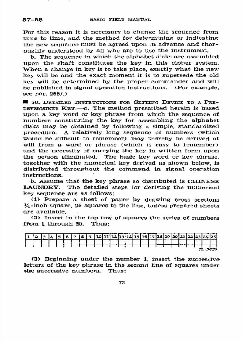
8/16/2019 (1942) FM 24-5 Signal Communication
http://slidepdf.com/reader/full/1942-fm-24-5-signal-communication 76/383
57-58 BASIC FIELD MANUAL
For
this reason it
is necessary to change
the
sequence
from
time to
time,
and the
method
for
determining or indicating
the
new
sequence
must
be
agreed
upon
in
advance
and
thor-
oughly understood
by all who are
to
use
the.
instrument.
b.
The sequence in which the alphabet disks
are
assembled
upon
the
shaft constitutes
the key
in
this
cipher
system.
When
a
change
in key is to
take
place,
exactly
what the new
key
will be and the
exact
moment it
is
to supersede the old
key will be
determined
by
the proper
commander and will
be published
in
signal operation instructions. (For example,
see
par.
265f.)
* 58.
DETAILED
INSTRUCTIONS FOR SETTING DEVICE
TO
A PRE-
DETERMINED KEY.-a.
The
method prescribed herein
is
based
upon
a
key
word
or
key
phrase from
which
the
sequence of
numbers constituting the key for
assembling the alphabet
disks
may
be obtained by following
a
simple, standardized
procedure. A
relatively
long
sequence
of
numbers
(which
would
be
difficult
to
remember)
may thereby
be
derived
at
will
from
a word
or
phrase (which is easy to
remember)
and the necessity
of
carrying
the
key in
written
form upon
the person
eliminated.
The
basic key word or
key
phrase,
together with the numerical key derived as shown
below, is
distributed throughout the command
in signal
operation
instructions.
b.
Assume
that
the key phrase
so
distributed is CHINESE
LAUNDRY.
The detailed
steps
for
deriving
the
numerical
key sequence are as follows:
(1)
Prepare
a sheet of paper by
drawing
cross sections
1/4-inch
square,
25
squares to
the line,
unless prepared sheets
are
available.
(2)
Insert in the top
row
of squares
the
series
of numbers
from
1 through
25. Thus:
1
2
3 5 6 17 18 19 0llllll-231l341l5161l71l819120121122 25
(3) Beginning
under the
number
1, insert
the
successive
letters of the key phrase in
the second
line
of squares under
the successive
numbers.
Thus:
72

8/16/2019 (1942) FM 24-5 Signal Communication
http://slidepdf.com/reader/full/1942-fm-24-5-signal-communication 77/383
SIGNAL
COMMUNICATION
58
1
2
3 4
65
7
8
9
10
1
12 13
14
15 16
19
18
1 20
22
23
24
2
C
H I
11N
S
E L
IA4D IR
TZ
-3235
(4)
Extend
the
key
phrase
by
repetition
until
there
is
a
letter
under
the
number
25,
making
a
key
sequence
of
25
letters.
(If
the
key
phrase
should
contain
more
than
25
letters,
those
after
25 are
merely
omitted.)
Thus:
11
2
3
4
5 61
7
18
9
1
1314
15161718192o2122123245
Cl
I
N EISIEILL
U
IN
IY
C
R
|I
N
E
S E
|L
IA
U
71-3235
(5)
Number
the
letters
of
the
key
sequence
serially
from
left
to right
in
accordance
with
their
relative
position
in
the
ordinary
alphabet.
The
letter
A
comes
first in
the
ordinary
alphabet, and
occurs
twice
in
the
illustrative
key sequence;
therefore,
write
the
number
1
under
the
first
appearance
of
A
in the
key
sequence
and
the
number
2
under
its
second
appearance.
Thus:
1
2 3
4 5
617
18
91
11
1211311411511611718192021222312425
I I
I I
I I I I
I1
1 172
)
The
next
letter
n the ordinary
alphabet
is
B.
x-LU
N
(6)
he
next
letter
in
he
ordenary
alphabet
is
B.
Ex-
amine
the
key
sequence
carefully
to
see
if
t ontains
the
letter
B.
Since
this
letter
does
not
appear
in the
key
sequence,
examine
the
key
sequence
for
the
letter
C.
This
letter
occurs
twice
in
the
illustrative
key
sequence.
Write
the
num-
ber
3
under the first appearance
of
the
letter
C
and the
num-
ber
4
under
the
second
appearance
of the
letter
C.
Thus:
1 2
3
4
5
6
7
8
9 1
11
12U13
145116
17
18
192021
22
23
24
25
C IR
IIN
E
S E
A
U
N
D
R Y
C
R
I INES
E L
1
U IN
131
1
4
1
1
1
1
14
2
T3-383
73

8/16/2019 (1942) FM 24-5 Signal Communication
http://slidepdf.com/reader/full/1942-fm-24-5-signal-communication 78/383
58
BASIC
FIELD MAMUAL
(7) The
next
letter
in
the ordinary
alphabet is D,
which
is
present
in
the illustrative key sequence. Assign the number
5
to
the
only
appearance of the letter
D
and
so on
through the
alphabet taking
each
letter
successively
and
assigning
the
next number
in
sequence
to
each
appearance of the
letter
in
the illustrative key.
The work
must be done
carefully
in
order that no letter
will
be overlooked. If an error is made in
the
early
stage
of deriving the key,
start
anew.
Be
especially
careful
with
letters
which
follow
each
other
in
the ordinary
alphabet,
but
which
are present
in
the key
sequence in re-
versed
order,
such
as
the
combinations
ED,
FE,
ON,
and
so
on.
It
is
easy
to make
a mistake
in these
cases
and
as a
conse-
quence,
the
assigned numbers
will appear
in reverse
order.
(8) When
the numbering process is completed and if the
work is
correctly
performed, there
will
be a
number
under
every letter of the key sequence and
the
highest number
will
be
25.
If
not, an
error has
been
made. Check
the work and
better
still,
if
two
clerks
are
available,
each should derive the
key
independently and
the
final results
checked
by
comparison.
(9)
The
key phrase selected for
the
foregoing example will
yield the following key:
3 45
6
7
_
9
1011 _
13
4
15
16
1718
19
221 22232425
I
N
E
S
E L A
U
N
DRY
E
I
N
ESELAU
N
3
10 11216
6 27 Il
2317
5
2
25_4
1131s8
_229
5 2
419
7 -3238
(10) This
sequence of
numbers indicates the order
in
which
the
successive
alphabet
disks are
to
be
assembled
on the shaft
from left to right. According to the foregoing key sequence,
place
the alphabet disk No. 3 on the shaft
immediately
to the
right of the
guide
rule
disk;
following disk No.
3,
disk
No. 10,
and
so on,
are
placed successively
to
the
right
of
the
guide-
rule
disk.
Disk
No.
19
is
the
last
disk
to
be
placed on
the
shaft using this particular
key.
When
disk
No.
19 is in place
on
the shaft,
put
on the retaining plate
and
the
thumb
nut.
Turn
the thumb nut on
to
the shaft sufficiently
to
retain the
assembly
and yet
permit the
revolving
of
the individual
disks
on the shaft. The
device
is
now
ready
for
enciphering
and
deciphering
messages.
74
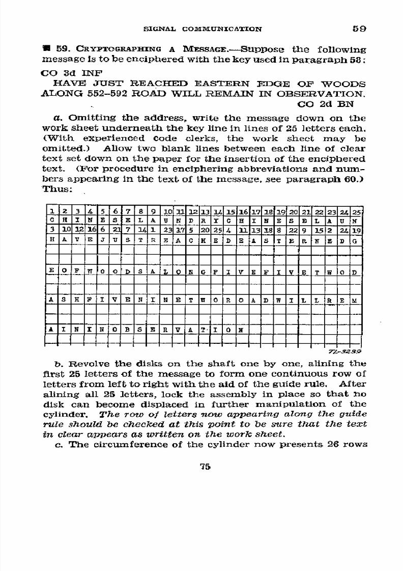
8/16/2019 (1942) FM 24-5 Signal Communication
http://slidepdf.com/reader/full/1942-fm-24-5-signal-communication 79/383
SIGNAL
COMMUNICATION 59
*
59.
CRYPTOGRAPHING
A
MESSAGE.-SUPPOse
the following
message
is
to be
enciphered with the key used in
paragraph
58:
CO
3d
INF
HAVE
JUST
REACHED EASTERN
EDGE OF
WOODS
ALONG
552-592
ROAD WILL
REMAIN IN OBSERVATION.
CO 2d
BN
a. Omitting the address,
write the message down
on
the
work
sheet
underneath the key line
in
lines of
25
letters
each.
(With experienced code clerks,
the work sheet may
be
omitted.) Allow two
blank lines between
each
line
of
clear
text
set
down on
the
paper
for
the insertion
of
the
enciphered
text. (For
procedure
in
enciphering abbreviations
and num-
bers
appearing in the text of the message,
see
paragraph
60.)
Thus:
1
2
3
4
5 6 7 8 9 1 U 13 _41511 1
11920
2122232425
C H I N
E
SE L A U N D
R Y
c H I N S E L A U N
3
10
12166
M
7
U 1
2317
5
25
4
13
1
8
229
152 24
19
HAV
E
J US T
R E A
H EDE
ASTERNED
E 0 F W 0 OID
S
A L
0
N G F I
V
E F I V
E T
W
0
D
A S H F I V E N I N
E
T U 0 R O A D W
I
L L
R E
M
A
I
N I N 0 B
S
E R V A T O
0
7Z-32S9
b. Revolve the
disks
on the shaft
one
by one, alining the
first
25
letters
of the
message to
form
one
continuous
row
of
letters
from
left
to
right
with
the
aid
of
the
guide
rule.
After
alining all 25
letters,
lock the
assembly
in
place
so
that
no
disk can become
displaced
in
further
manipulation of
the
cylinder.
The row of
letters
now appearing along the
guide
rule
should
be checkec
at
this
point to be sure
that
the
text
in clear appears
as
written on the work sheet.
c.
The
circumference
of the
cylinder now
presents
26
rows
75

8/16/2019 (1942) FM 24-5 Signal Communication
http://slidepdf.com/reader/full/1942-fm-24-5-signal-communication 80/383
59
BASIC
FIELD
MANUAL
of
letters,
24
of which
are
visible,
the
remaining
two
being
hidden
or
partially
obscured
by
the
guide
rule.
One
of
the
24
visible rows
is
the
clear
text
row;
the
remaining
23
are cipher
text
rows,
any
one of which
may
be
used
as the
cipher
text.
Select
one
of the
cipher
text
rows
at
random and
write
the
letters
composing
this
row
immediately
under
the
clear
text
on
the
work sheet.
Assume
that
you
chose
the
row
begin-
ning
JUKLD,
the
first
row on
the
work
sheet
would
then
read
as
follows:
1 2
3 4
1567
8 9
1
0_12
1_ 15116117118119120
21
2212S124125
C. RHI
E
S E L
A U I
D
IR
Y C
H I N E
S
E L
_ U N
3
1o0
2166
7 4
1 231
5
2 0254
_113188
22 9
152
2419
B A V E
J U
S T
R
E
A
E
D E A
S T
ER RI.
E D G
J U 1K
D
Y K I
T Z
II
V C y
P Y h
J
It is
not
necessary
to
make
a
record
of
the
cipher
text
row
(above
or below
the
plain
text
row)
used
as
the cipher
text
nor
is it
necessary
to indicate
anywhere
in the
cipher
text
which
row was
used.
d.
Loosen
the
thumb
nut
but
do not
remove it
from
the
shaft. Aline
the
next 25
letters
of the
plain
text
as in b
above
and
tighten
the
thumb
nut once
more.
Recheck
your
work
and
then
select
another
cipher
text
line from
the
23
lines
available,
except
the one
used
in enciphering
the
first
line
of
the text.
Write
the
cipher
line
thus
obtained
under
the
second
clear
text
line
on
the
work
sheet.
Assume
you
select
the
line
beginning
YUYEZ,
the work
sheet
will
now
appear
as
follows:
1
2 3 4
5 6
7 8
19
31516171192 2122232425
C H I
N
E
S
EE
L
U
N
R
C
E
S
L
N
3 1012166
217
14
12311715
202514
13118
2291522419
HAVEIUSTREACHEDE
ASTERNEDG
J
U
KLD
Y
ITZII
VC
YCVUYVPYW
HJ
E
1
|F
| 1 |D
s |L
1 |G
I
V|E
F I V
E T l
1
D
y u 1y
|E lZ
|D |H V
U lZ
DD BQ
P
O
°Z
|M
IC |F
N |B
IJ
J7I
X32
76

8/16/2019 (1942) FM 24-5 Signal Communication
http://slidepdf.com/reader/full/1942-fm-24-5-signal-communication 81/383
SIGNAL COMMUNICATION
59
e. Continue this process in a similar
manner with the third
line of plain text.
Do not make a
practice of selecting
any
particular line of
cipher
text
above
or
below
the clear text.
Avoid
the selection
of
the
line
above
the
clear
text
line and
the
line below
the guide rule.
Assume
that
instructions
have
been followed
up
to
this point
and
that you
have
selected
the
cipher text row
beginning EAPTH to represent the
third
line
of
clear text, the work sheet now
appears as follows:
1
2 3
4
5 6 7 8 9 lOL11221131415s16171189192022122324125
CH I
N E
S
EL
ATU
N
DRYC H
I
N
E
S E
L
A
U
N
3
10
1i6
27
1 23
175
20254 1113188
229 152
2419
H A V
E J U
S
T R
E A C
E
D
A S T E R
N E D
G
J
U
K L D Y
K
I
T
Z I I V CY UY
P Y W H
J
E
0 F W 0 0 D
S
A L
0
N
E F
I
E
T W O
D
A
S
NFIVEN I
N E T W C l
R
0
A D W I
L
EL
IR
E
MD
YUYEZDBVUZDBQP
OZM0F:BJ
JIX
ASHFIVENINETWORO AwILLREL
E A
P T W K W W
T
N Y G M P R Z
J I F A D
f. Because the signature
is
not enciphered, there
are only 16
letters remaining
to be enciphered which are
not
enough to
complete
a row of cipher
text. Aline this third
line of
clear
text
consisting
of
16
letters
and
select
a
row
of
cipher
text
556773°-43-6
77

8/16/2019 (1942) FM 24-5 Signal Communication
http://slidepdf.com/reader/full/1942-fm-24-5-signal-communication 82/383
59
BASIC
FIELD
MANUAL
to
represent
them.
Assume
that
you select
the
row
beginning
MEQRH,
the
work
sheet
now
appears
as follows:
1 2
3
4 5 6 7
8 9 1011112131
15 17181920
212223
2425
C H
I N
E
S E
L
A U N D
R Y0
HC I N
E S E
L
A U
N
3
10
1
6
22 7
1
23175
202514
11
3
18
229
15
24
19
H
A V E
J
U S T
R E A
C
E
E A
T E
R
N E D
C
J U
K
L D
Y
K I T
Z I
V
Y
P Y W
H
J
E 0
F
A L
0
N
IVE
IV
ETW
D
Y
U Y E
Z
D
V U
Z
D
B Q P
0
Z
MC
F
N
B JJ
I
X
A S
H F I V
E N I
N
E
T
W
0 R
0
A D W
I L LR
E
M
E A
P T
HY0
W H
K W
W T N Y
GM P
R Z J
I F A
D
A
I N
I
N
0 B
S E R
VATION
M
E
Q
R
H B P
0
J T
Y
U Q
N T
W
-L-3-ç
g.
Now
copy
the
cipher
text
on the
message
form
in
five-
letter
groups.
It
will
then
appear
as
follows:
JUKLD YKITZ
IIVCY
CVUYV
PYWHJ
YUYEZ
DHVUZ
DBQPO
ZMCFN
BJJIX
EAPTH
YOWHK
WWTNY
GMPRZ
JIFAD
MEQRH
BPOJT
YUQNT
W
h.
The
last
group
of
the
message
is
not
a
complete
group
of five
letters;
make
it
a complete
group
by
adding
four
X's.
These
are
not
cryptographed,
but are
merely
added
to
com-
plete
the
cipher
group.
The
final
work
sheet
on
this mes-
sage
will appear
as follows:
JUKLD
YKITZ
IIVCY
CVUYV
PYWHJ
YUYEZ
DHVUZ
DBQPO
ZMCFN
BJJIX
EAPTH YOWHK WWTNY
GMPRZ JIFAD
MEQRH
BPOJT
YUQNT WXXXX
The
message
as it
now
appears
is
one of
many
forms
in
which
the
enciphered
text
might
appear
externally,
de-
pending
on
which
of
the
cipher text
rows
were
selected
for
each
line
of the
encipherment.
78

8/16/2019 (1942) FM 24-5 Signal Communication
http://slidepdf.com/reader/full/1942-fm-24-5-signal-communication 83/383
SIGNAL COMMUNICATION'
59-61
i.
All
work
sheets utilized in
cryptographing
the
message
will
be
destroyed
by burning.
* 60.
CRYPTOGRAPHING
ABBREVIATIONS,
PUNCTUATION
SIGNS,
AND
NUMBERS.-a. Authorized abbreviations appearing in
the
orig-
inal
plain-text
message may
be enciphered as abbreviations
without
periods. Examples:
Am
Tn=AMTN; E. V. Brown
Sch=EVBROWNSCH.
b. The writer of
a
message must spell out the punctuation
signs he
wishes
transmitted; for
example,
STOP,
COMMA,
COLON, etc.
Otherwise
punctuation signs will not be
trans-
mitted.
(See
par.
38a(3).)
e.Cardinal and ordinal numbers when spelled out
in
let-
ters in
the
original plain-text message are always enciphered
exactly as spelled.
d.
Cardinal numbers when
expressed
in
figures
in the
origi-
nal plain-text message must be spelled out
digit
by
digit in
cryptographing.
Examples:
4=FOUR
40=FOURZERO (not FORTY)
400=FOURZEROZERO
(not
FOUR HUNDRED)
455 =FOURFIVEFIVE
2005=TWOZEROZEROFIVE
12.01
AM=ONETWOZEROONEAM
5.15 PM=FIVEONEFIVEPM
To save time
in
the
encipherment
of
numerals,
an abbrevi-
ated
method
of
substituting
one
letter
for each
of
10
digits
may be
authorized
in signal operation
instructions.
Thus
"ALONG 552-592" might be enciphered
as
"ALONG JJP
DASH JBP." The
substituted
letters must then be enci-
phered.
e.
Ordinal numbers above the ordinal number 10th, when
expressed in
figures
followed by
"d",
or
"th", are
crypto-
graphed merely
as digits spelled out without adding
the
"d"
or
"th." The
omission of
the "d"
or
the
"th" will
cause
no
confusion or ambiguity. Examples: 3d
Bn=THIRDBN;
7th
Pk
Tn=SEVENTHPKTN; 11th
Rgt=ONEONEREGT; 403d
Am
Tn=FOURZEROTHREEAMTN.
· 61.
DECRYPTOGRAPHING
A
MESSAGE.--a.
If the key
word
or
key phrase
is
known, the numerical key
sequence
can be
de-
79
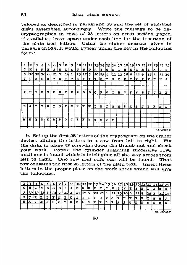
8/16/2019 (1942) FM 24-5 Signal Communication
http://slidepdf.com/reader/full/1942-fm-24-5-signal-communication 84/383
61
BASIC
FIELD
MANUAL
veloped
as
described
in
paragraph
58
and the
set of
alphabet
disks
assembled
accordingly.
Write
the
message to
be de-
cryptographed in
rows
of
25
letters
on
cross
section
paper,
if
available;
leave
space
under each line
for the insertion
of
the plain-text
letters.
Using
the
cipher
message
given
in
paragraph
59h,
it
would
appear
under the
key in the
following
form:
1 2 34
5
6 7 8 9
1011 1213 14151617181920
21 222324
25
0 H I
N
E
S E L A U
N D R Y C
E I N E S
E
L
A
U N
31012
6
2 7 1 23
175 2025
4 13 18
229
152
2419
J U K L
DY E
I T Z
I V C
y C
v
ur YV
P
Y
W
L
J
U Y
E Z D H
V U
Z D BQ P
0
Z
M F NB JJ
I X
EA
P
T
HY W
HK W
WTNYG
M
P
RZ J
I
F
A
D
uEQRHBPoJ
0 U
T
7L-3244
b. Set
up
the first
25 letters of
the
cryptogram on
the cipher
device,
alining
the letters
in a row
f rom
left
to
right.
Fix
the
disks
in
place
by
screwing
down
the t humb nut
and
check
your
work. Rotate
the
cylinder
scanning
successive
rows
until one
is
found
which
is intelligible
all the
way across from
left to right.
One row
and only one
will
be
found.
That
row contains
the first
25
letters of
the plain text.
Insert these
letters in
the proper place
on the work
sheet which
will give
the following:
1
23 4
5
6
7 8
9
11oI1112
¡13
14115I16117I1819
2Oi21I2222324¿
25
0H
I NE SIE L
A
|U |N
IDR
r IC
H |I IN
E
1S
IL
IA U N
3
1
12 1
6
127I1 1I23I17
5
20 2514
11111311818
2219
11512 124119
J U E
L D
Y K I
T
Z II I V IC
I I
u|
Iv
P
IYw J
A I
T
R
E
A
CH ID E
1
S E
RN
EDG
7L
-3Z
80

8/16/2019 (1942) FM 24-5 Signal Communication
http://slidepdf.com/reader/full/1942-fm-24-5-signal-communication 85/383
SIGNAL
COMMUNICATION 61-62
c.
Loosen
the
thumb
nut and set
up
the next 25 letters
of
the cipher
text. Lock the assembly
in position
and
again
check your
work before
scanning the rows for
one
containing
plain
text.
Again
write these
25
letters
down
in
their
proper
place
on the work sheet
and
continue
the
process
until the
whole message has been
decryptographed.
d. If
any
difficulty is experienced
in picking
out a
plain
text
row, the context of the preceding row should
give
a good
clue
as to
the plain text following
it.
In
the
message
illus-
trated
above, the last
four
letters of the group
are
not
to
be
decryptographed
since
they
were
merely added to
make
the
last
group of
the cryptographed
text
a
complete
group of
five letters. Omit them
from
the work sheet.
e.
Copy
the
plain
text message
on
a message form. The
code
clerk may, if
authorized
to do so by the message
center
chief, convert the numbers which
had
to
be
spelled out
to
be
enciphered to their
equivalent
arabic numerals. Copy ab-
breviations
and
punctuation signs
exactly as they
stand
in
the
decryptographed
message.
SECTION
VI
CONVERTER M-209
E1
62. DESCRIPTION
AND
USE.-a.
Converter
M-209
is
a small,
hand-operated,
all-mechanical cryptographic machine
that
is
an item
of
equipment
issued
by
the
Signal
Corps to all
message
centers
serving
units
below the division,
and to
cer-
tain types of
armored force
vehicles,
and
aircraft.
In
enci-
phering,
it makes
a printed
record
of the cryptogram; in
de-
ciphering,
it
makes a printed
record
of the
plain text
message.
Its
speed of
operation
is
approximately
12 groups
per
minute.
b.
TM
11-380
contains
detailed
information regarding
the
construction and operation of the
machine,
necessary ad-
justments, and repairs.
While
the manual
may
give
illustra-
tive examples of keying arrangements, specific
cipher
keys
which
are
employed
in
actual field
operations
are
issued in
signal
operation
instructions.
81
8/16/2019 (1942) FM 24-5 Signal Communication
http://slidepdf.com/reader/full/1942-fm-24-5-signal-communication 86/383
CHAPTER
3
MESSENGER COMMUNICATION
Paragraphs
SECTInoN
I.
General _______________________________________ 63-65
II. Training
of personnel -________-______________
66-71
III. Employment
-________-________---____-
______ 72-81
IV.
Dropped messages
__________-______-----______
82-85
V.
Pick-up
of
messages
____________--------------
86-90
SECTION
I
GENERAL
* 63.
GENERAL.-Messenger
communication
is
needed
and
used by
all
units from
the
smallest to
the
largest.
Both
per-
sonnel and
equipment are
necessary
for
messenger
communi-
cation, but
of
all
means
of
signal
communication,
it
is
most
dependent upon personnel, and only to a
minor
degree upon
equipment. All persons in
the military
service
are
directed
to assist messengers
carrying
important orders
or
messages
by pointing
out the
route, giving directions, and
providing
transportation
if necessary.
E 64. PERSONNEL.-a.
The
personnel needed for
messenger
communication
consists
primarily
of
messengers,
but agents,
airplane
pilots,
observers, and
others
are required
in
special
situations. Usually messengers
are a part of message
center
sections of units operating a message center, but if
they
are
not, they should be attached to those
sections for
training and
employment. These additional
messengers will
be provided-
from personnel
other than communication personnel by the
commanding
officer
of
the unit which the message center
serves.
(1) Messengers
are
persons
who
carry
messages as
defined
in paragraph 5. In
the
field a dismounted messenger is
named a
runner.
Other
messengers
are named
according
to
the means of transport used
by
them; as, mounted (horse),
bicycle, motorcycle, motor, and airplane.
(2) Agents
are special messengers,
usually
noncommis-
82
8/16/2019 (1942) FM 24-5 Signal Communication
http://slidepdf.com/reader/full/1942-fm-24-5-signal-communication 87/383
SIGNAL
COMMlIUNICATION
64-65
sioned
officers,
employed
by commanders
for
liaison with
sub-
ordinate,
adjacent,
or supported
units (see
pars. 71
and 81).
b.
The
great
dependence
of
messenger
communicatiof upon
personnel
necessitates
that personnel
should
be
selected
with
the
following
characteristics
as
a basis:
(1)
Motorcycle,
bicycle,
mounted
messengers,
and runners
should be
young
and sturdy.
(2)
Messengers,
especially
runners and agents,
are re-
quired
to
have courage
to
a
marked
degree.
They are often
sent on
important missions
the accomplishment
of which
requires
extraordinary
self-reliance
and
endurance.
(3) Messengers
and agents
are required
to
have an
intel-
ligence
above the
average.
They
must
be
resourceful,
able
to
comprehend
simple
oral orders,
to
use compasses
and
maps,
and to
understand
changes
in tactical
situations.
(4)
Extreme
loyalty
is necessary
to insure
trustworthiness.
In
messengers,
loyalty
and courage
will
compensate
to
some
extent
for
deficiencies
in
physique.
These
men
must carry
out
their
instructions
and
duties with care
and
certainty.
* 65. EQUIPMENT.-All
messengers
should
be provided,
when
necessary,
with
a compass and
a
message-carrying
bag.
In
addition,
all except runners and
some
agents,
require
a
means
of transportation.
A
motor
messenger
may be
the
driver of
a vehicle
or he
may
be an additional
occupant,
depending
upon
the circumstances.
Commanders
of
all
units
may find
it
necessary in
an
emergency to utilize,
for
messengers,
any
motor
vehicle assigned
to their
units.
The
motor vehicle
park for
messengers
should be several
hundred
yards away
from headquarters.
Motor
messengers
should
be
instructed
to
exercise
caution
in
the manner
in which
their
vehicles
are
parked
in
order
that
they may
be immediately
accessible
and
at
the
same
time not
visible
to enemy
observation.
Message
center
officers
should
take
advantage
of motor
transport
and
trains
traveling
over
routes
used
by
messengers
as a
means
of
transportation
for messengers.
An airplane
may
have
solely
a messenger
mission,
it may
perform such
a mission
in
addition to
its other
work, or
it may
be used
only to trans-
port
an
ordinary
messenger.
See sections
IV
and V
for the
equipment necessary
for
dropping and
picking up
messages
by
airplane.
83
8/16/2019 (1942) FM 24-5 Signal Communication
http://slidepdf.com/reader/full/1942-fm-24-5-signal-communication 88/383
06-68 BASIC FIELD MANUAL
SECTION II
TRAINING OF PERSONNEL
*
66. BASIC.-See
TM
11-450 for the
minimum training
spec-
ifications for
signal
specialists, and particularly
those
for
a
basic
private,
a basic
corporal,
and a
basic
sergeant. The
training
outlined in
the
paragraphs
below
for messengers,
except
airplane pilots or observers,
follows
the
completion
of
the
training for
a basic private
and
that
for agents
follows
the
completion
of
the
training
for
a basic
corporal
or
sergeant.
E 67. RUNNER.-The
runner
will
be qualified
in-
a. Transmitting oral and
written
messages.
b. Traveling
across
country
over
various kinds
of ground at
the
prescribed
rates. (See par.
75c.)
c. Using a compass
as
a
means of orientation
and
as
a
means
of following
a
given
azimuth.
d.
Reading
maps and
orienting himself
by stars
or sun
so as to
locate
routes,
terrain features,
and troop
positions,
and
to
be able
to follow highways,
ravines,
streams,
and
telephone
or
telegraph
lines.
e.
Selecting routes
from map
or ground
that
will furnish
the best cover and
concealment
consistent
with
time limit of
delivery.
f. Observing
and reporting
troop
movements.
g.
Recognition
of
officers,
units,
ornaments,
and
insignia
with
which
they are associated. (In the combat zone where
use
of
ornaments
and insignia
is
limited,
the
runner
should
be
taught to question
guides to identify
officers
and
units.)
h.
Conveying
information
and orders by whistle,
by
con-
ventional arm and hand signals,
and
by
prearranged flag or
light
signals.
i. Using
a delivery list and
message envelope
as a receipt
form.
U 68. MOUNTED
MESSENGER.-In
addition to the
training
of
a
runner,
a
mounted
messenger
will be qualified
in-
a.
Feeding,
watering,
and grooming
animals.
b. Saddling
and
bridling animals,
and adjusting
their
equipment.
84
8/16/2019 (1942) FM 24-5 Signal Communication
http://slidepdf.com/reader/full/1942-fm-24-5-signal-communication 89/383
SIGNAL COMMUNICATION
68-71
c. Care of
animals in garrison and
field; to include recog-
nition of common ailments,
administration
of necessary
first-
aid
treatment,
and
care
of
back
and feet.
d. Equitation,
including
riding at
all gaits
over
varied
terrain.
e. Covering specified
distances
in specifled times, all
within
the
limits
of
endurance
of
the animal.
f.
Concealing and
protecting
animals
during
combat.
* 69.
BICYCLE, MOTOR, AND
MOTORCYCLE
MESSENGERS.-In
addition
to
the training
of
a runner, bicycle, motor,
and
motorcycle messengers
will be
qualified
in riding,
driving,
and
caring for
the vehicle which transports
them, and
in
traveling in accordance with
traffic
regulations
and
rules of
the
road.
* 70. AIRPLANE
MESSENGER.-If
the airplane messenger is
the
pilot
or observer,
he
will be qualified
in radio
and visual
communication,
and
in dropping
and
picking
up
messages,
all
of
which
are
covered
elsewhere
in
this
manual.
(See
pars.
82
and 86.)
* 71. AGENT.-An
agent
is
a soldier acting as
a personal rep-
resentative of
a commander
at
the headquarters of
his
next
superior commander. The agent
will be qualified in-
a. Transmitting oral
and
written messages.
b. Receiving and transmitting messages accurately
by
tele-
phone.
c. Using
the
message blank.
d.
Using the compass.
e.
Reading
maps.
f.
Making a
simple sketch.
g. Observing and reporting troop
movements,
troop
posi-
tions,
and
terrain features.
h.
An
elementary
understanding of the
organization
and
tactical
employment
of
his
unit and
of
the
unit
to which
he
is sent.
i.
Conveying
messages by
visual signaling
with flags and
lights, or
by
conventional or prearranged
arm
and
hand
signals.
85
8/16/2019 (1942) FM 24-5 Signal Communication
http://slidepdf.com/reader/full/1942-fm-24-5-signal-communication 90/383
72-73
BASIC FIELD
MANUAL
SECTION
III
EMPLOYMENT
*
72.
GENERAL.-FOr further
details
as
to the
employment
of
messengers,
see
chapter
2.
* 73. SELECTION OF TYPE
OF MESSENGERS USED.-The
effec-
tiveness of messenger
communication
is
largely dependent
upon
the selection of the proper type of messenger.
This
selection is based
upon
the urgency,
length,
or bulk of
the
message,
terrain,
weather, and
types
of
messengers
and
trans-
portation
available.
a. Runner.-Runners
are
used when other means
of signal
communication
'will not function
in a dependable
manner,
when
other means
become
overtaxed, when
distances
are
short or the
route is
impassable
for other messengers,
and
also
in
small
units not provided with other
means
of
com-
munication. The
runner
is
able
to
go
where
other
types
of
messengers cannot go, and he can conceal
himself
more easily.
He
should not,
however, be used
for long
distances,
unless
relays are
established.
b. Mounted,
bicycle,
and motorcycle.-Messages are
sent
by
mounted, bicycle,
and
motorcycle messengers
when
the
enemy situation and the
condition
of the route permit
the
use
of
horses, bicycles,
or
motorcycles.
c.
Motor.-Motor
messengers
are normally
used
between
headquarters
separated by not more
than
4
hours' motor
time,
when
the mail service
will
not
suffice. They may
be
placed on
a routine schedule or
may
be subject to call as
required.
d. Airplane.-(1)
The commander
of
a
division
or higher
unit who
has attached aviation
or
commanding
officer of
any
air
force unit
may assign airplanes
to
the messenger service
when
other
means
of
signal
communication
will
not
suffice.
Important
messages
transmitted
between widely separated
units or between allied armies may be best delivered by air-
plane.
(2) Messages
may
be handed
on
the
ground
to
the
pilot,
observer, or a messenger
traveling
in the airplane, or deliv-
ered
to the
airplane in flight by radio, panels,
pyrotechnics,
pick-up,
flag or
lamp
signals,
or
other
means.
(See sec.
V.)
86

8/16/2019 (1942) FM 24-5 Signal Communication
http://slidepdf.com/reader/full/1942-fm-24-5-signal-communication 91/383
SIGNAL
COMMUNICATIOlN
73-75
(3) Messages
transmitted
by
airplane may
be
delivered
directly
by the
pilot, observer,
or other messenger
on the
ground;
or
from
the airplane
in
flight
by
radio,
pyrotechnics,
or other visual
means, or by dropping.
(See sec.
IV
below.)
U 74. RECEIPT
OF
MESSAGES
FOR DELIVERY.---.
The officer or
noncommissioned
officer
directing
the transmission
of a
message gives the
messenger the
following information:
(1)
Name and location of the
headquarters
or person to
whom the
message is to be delivered.
(2)
Route
to
be
followed
unless
left
to
the
messenger's
discretion.
(3)
Danger points
to
be avoided.
(4)
Speed
required.
(5)
Whether or not
an answer
is expected.
(6)
Where
to
report
upon
return.
(7) Where to report
in
case
the message is not
delivered.
(8)
Special instructions,
if any.
(9)
Contents
of
the
message
if
the
situation warrants.
b.
When
one
or
more
messages
are
entrusted
to
a messenger,
a
delivery
list is attached,
or he
is
directed to
obtain receipts
on
the envelope or other
receipt form.
c.
The
messenger
is instructed
to
report his
destination to
the
nearest
leader when passing an
outpost
or other line estab-
lished by a
security
detachment. This officer
or noncommis-
sioned
officer
should orient
the messenger
and lend aid,
if
required,
to
expedite the delivery.
(See par. 63.)
U 75.
CARRYING
MESSAGES.--C.
Messages
will be
carried in
the
message-carrying
bag when one is
provided.
If
none
is pro-
vided, the
messages
will be
carried
in the upper
left-hand
of the
blouse
or
the left-hand
of the shirt.
Bulky packages
are carried
in
the hand or
under
the
arm.
In
inclement weather they
should be
protected by
a
raincoat or
waterproof
covering.
b.
When
the
situation
permits,
messengers will
travel
by
covered
routes. When approaching
or
leaving command
posts,
messengers will
be
particularly
careful
to avoid
disclos-
ing the location to
hostile
air
observation.
They
should use
such
measures
as
are necessary
to
insure prompt delivery and
to
prevent needless exposures.
When
practicable,
routes
over
difficult
terrain
which
may be traversed
at
night
should be
reconnoitered during
the day by the messengers
who will use
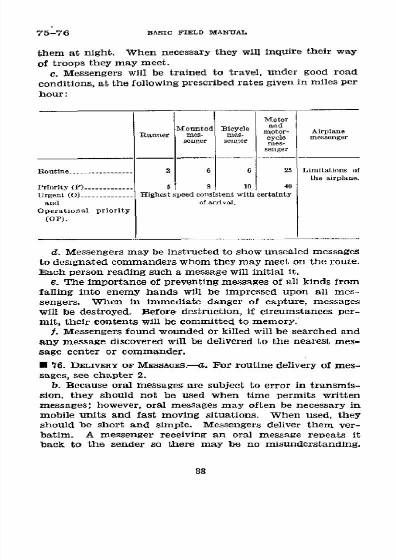
8/16/2019 (1942) FM 24-5 Signal Communication
http://slidepdf.com/reader/full/1942-fm-24-5-signal-communication 92/383
75-76
BASIC
FIELD
MANUAL
them at
night.
When
necessary
they
will
inquire
their way
of
troops they may
meet.
c.
Messengers
will be
trained
to
travel, under
good
road
conditions,
at
the
following
prescribed
rates
given in
miles per
hour:
Motor
Mounted
Bieycle
and
Runner
mes-
mes- motor-
Airplane
l~unner
roes-
mcs-
cycle messenger
senger
senger
mes-
messenger
senger
Routine
.- -----.-.---
3
6
6
25
Limitations
of
the airplane.
Priority (P)
-5
8
10
40
Urgent
(O)
.-
.
..........
ighest
speed
consistent
with certainty
and
of arrival.
Operational
priority
(OP).
d. Messengers
may be
instructed
to
show
unsealed
messages
to
designated
commanders
whom
they
may
meet
on
the
route.
Each person
reading
such a message
will
initial it.
e.
The
importance
of preventing
messages
of all
kinds
from
falling
into
enemy
hands
will be
impressed
upon
all
mes-
sengers.
When
in
immediate danger
of
capture,
messages
will be
destroyed.
Before
destruction,
if
circumstances
per-
mit, their
contents
will be
committed
to memory.
f. Messengers
found
wounded
or killed will
be
searched
and
any
message
discovered
will be delivered
to
the
nearest
mes-
sage
center
or commander.
* 76. DELIVERY
OF MESSAGES.---.
For
routine
delivery
of mes-
sages, see chapter
2.
b. Because
oral
messages
are
subject
to
error in
transmis-
sion, they
should not
be used
when
time
permits
written
messages;
however,
oral messages
may often
be
necessary
in
mobile units
and fast
moving
situations.
When
used,
they
should
be short
and simple.
Messengers
deliver
them
ver-
batim.
A messenger
receiving
an oral
message repeats
it
back
to
the
sender
so
there
may
be no misunderstanding.
88
8/16/2019 (1942) FM 24-5 Signal Communication
http://slidepdf.com/reader/full/1942-fm-24-5-signal-communication 93/383
SIGNAL COMMUNICATION
76-78
The messenger repeats
it to himself until he has
committed
it
to
memory.
c.
Messengers
may
at
times
be
required
to
carry
back
a
reply or
other
messages
destined for
their
own command.
However,
their
return
will
not be delayed
for
this purpose.
d. When the
headquarters,
message center, or
the
individ-
ual
addressed cannot
be found
without
undue
loss
of time,
messengers will report to
the
nearest headquarters and
request
instructions.
e.
Messengers
whose transportation
has become disabled
will
continue
to
their
destination in
the
most
practicable
man-
ner.
It may be
advisable
to report to
the nearest head-
quarters
for
assistance and
instructions.
In
event
of
being
incapacitated by wounds, they should
turn
their messages
and
instructions
over
to
any
reliable person whom
they may
encounter.
When
such
action
is
necessary
they
will keep a
record
of the person, time,
and
place
and
turn
it
in
at the
first opportunity to
the
message center or to the person from
whom
the
message
was
received.
f. Messengers will
travel
in accordance with instructions
from
the
messenger
dispatcher. In
the presence of
a person
not definitely recognized as a
member of
their own
army,
messengers will make no mention of the
direction from
which
they have come or of their destination.
g.
Messengers will help
other means
of signal communica-
tion to function
when
it
is
possible
to do
so
without
inter-
fering with their
own
task.
For
instance,
if they discover
breaks
in wire lines
they
will
report
the
location.
* 77. DOUBLE
MESSENGERS.-Double
messengers should be used
when the mission
is
important or dangerous, such as move-
ment through
hostile
territory,
past enemy
patrols,
over
ground
swept
by
small-arms fire,
or
over heavily shelled areas.
Double messengers must
keep within
sight
of
each other
yet
remain separated
by
such
distance
as
will
prevent both
being
exposed to hostile fire
or
ambushed
at
the same time.
Each
should
carry
a
copy of
the message.
It
is
sometimes advisable
to send messengers over several routes
at the same time.
* 78. ROUTES.---a.
Routes
over which messengers
are
to travel
usually
will
be selected
by the officer
or noncommissioned
89

8/16/2019 (1942) FM 24-5 Signal Communication
http://slidepdf.com/reader/full/1942-fm-24-5-signal-communication 94/383
78-80 BASIC FIELD
MANUAL
officer
in
charge.
They must
be
chosen
with due
regard
to-
(1) Type
of messenger
which is
to be used.
(2) Concealment
from enemy
observation.
(3)
Availability
under
existing orders
or traffic
conditions.
(4)
Length
and
condition.
b.
Messengers
must be
instructed
very
carefully
as to
the
routes which
they
will follow
in traveling
to their destination.
Ordinarily
signs will
not
be
used to
point
the way; in
lieu
of the
signs, guides
are posted
at intervals
along
principal
routes
and
at crossroads
to
direct traffic
and
messengers.
c. It
may
be
advisable
to
send
messengers
over
routes
once
by
daylight,
preferably
with other
messengers
who
have
been over
the route.
Through
difficult
terrain,
runners
may
be instructed
to follow
telephone wires
maintaining their
direction
at night by letting a wire
pass through the hand.
Wires
may be laid to
guide
runners at
night or through
dense woods.
Alternate
routes are
selected whenever
the
principal route
cannot
be used because
of
congestion,
enemy
observation,
or
shelling.
*
79. SCHEDULED
MESSENGERS
(par. 39f).-When
periodic
trips are desirable,
a scheduled messenger
service is arranged
by message centers
and
the necessary
assignment of messen-
gers
made
in accordance therewith.
The
messenger dis-
patcher will
equalize the
work
assigned to
messengers.
C
80. RELAY
POSTS.-Relay
posts are
established
when
mes-
sages
must
be
carried frequently
between
the
same
points
or
units and
when,
by reason
of distance, difficulties
of
terrain,
or
hostile activity,
the
physical
strain and danger
of casualty
render
the operation
of
through
messengers
too arduous
and uncertain. A chain
of relay
posts may
be organized
from
a
squad or similar
group
of men
trained
to
function
as such
and
operating
under
the
normal
group leader who
is respon-
sible
for
its
operation
and
for
the
replacement
of
casualties.
Posts are preferably double
or
multiple to lessen the chance
of
interruption
through
casualties. Relays
may also
be used
when
a change in
the method of transportation
en
route
is
necessary.
Relay
posts
exposgd to enemy
raids should be
of sufficient
strength
to
provide
for their
own
security.
90
8/16/2019 (1942) FM 24-5 Signal Communication
http://slidepdf.com/reader/full/1942-fm-24-5-signal-communication 95/383
SIGNAL
COMMUNICATION
81-84
U
81. AGENTS.-a. Below
the
division
all
necessary informa-
tion can
usually be
obtained or distributed
through
reports
and field
orders, though
agents
prove
useful
in special cases.
During
combat,
agents may
be
exchanged
by
adjacent
pla-
toons or
larger
units.
b.
A headquarters
or unit
sends out an
agent
or agents
when
the
service
of information,
need
of
coordination,
or
special
occasion requires
his
particular
service.
An
agent
may
deliver
instructions,
transmit information,
perform
duties
of reconnaissance,
or work as guide.
c.
Agents
will be
instructed regarding
the
information
which
they
are
to
furnish
to, and
request
from,
the
head-
quarters or
unit
to
which
they are sent.
These
instructions
usually
concern
the disposition,
location,
and movements
of
units,
command
posts,
and headquarters;
and
the intention,
plan,
success,
and
failure of
operations.
Agents will
be given
information
which
may
be of
value
to
their
respective
unit
commanders and
they
will transmit
such
information
as soon
as
practicable
thereafter.
SECTION IV
DROPPED
MESSAGES
lb 82.
UsE.-Normally
messages
are dropped
by
airplane
ob-
servers
only
to
units
down
to and
including
the
battalion;
but
by
prearrangement,
messages
may
be dropped
to any
unit, detachment,
or
individual.
During
heavy shelling
by
friendly
batteries,
messages
usually
are not
dropped
to units
in
front
of the
light
artillery
positions.
* 83. DROPPING
GROUNDS.-Message
dropping
grounds
or
panel
display
grounds
are located
near the
radió station.
Panels
are
displayed
on
these
grounds when
there
is
a
mes-
sage
for the airplane
observer
or
when
the
observer
calls
for
panels.
A
dropping ground
should
be
an
open
space removed
from high
trees,
bodies
of water,
and
weeds. (See
pars. 87
and 150.)
By
prearrangement,
messages may
be
dropped
at
any predetermined
point
where
panels may or
may
not
be
required
to
indicate
the
dropping ground.
* 84. PROCEDURE.-Wh
en
it
is desired
to
drop a
message to
a
particular
unit,
a prearranged
pyrotechnic
or other
signal,
91
8/16/2019 (1942) FM 24-5 Signal Communication
http://slidepdf.com/reader/full/1942-fm-24-5-signal-communication 96/383
84-85
BASIC
PIELD MANIAL
meaning
"display identification
panels," is
made
when
the
airplane
is over the unit
for which
the message
is
intended.
The
unit's
assigned
identification
panels
are
then
displayed,
and the message is
dropped
from the airplane
as
near as pos-
sible
to
the identification panel
display.
When
the location
of
the
unit
for
which
the message is intended
is
known,
or
if
conditions
of
combat require it, the message
may
be
dropped
without
a
request for
a
display
of identification
panels.
Therefore,
on the
approach
of a friendly airplane, all
ground
troops
should
observe
the airplane
for a
dropped
message.
Whether
or not
prearranged
signals
are made from
the air-
plane,
the message will be
picked up
by
the
nearest
troops
and taken
at once to the commanding
officer or his repre-
sentative.
Ground troops
will indicate
that the message
has
been received
by
means
of a prearranged
panel
display or
other signal,
such as
waving
the
message bag or container
after it has been
retrieved.
After the drop
message
has been
delivered
to
the
commanding
officer
or
his
representative,
the
message
bag or container will be
returned by
mail or sched-
uled messenger to the nearest Army Air Forces
troops.
*
85.
EQuIPMENT.-a. Bags,
drop-message, Air
Corps, type
A-1, are provided
as a part of the equipment
of practically all
combat airplanes.
The quantity provided depends
upon the
use and the probable
needs
of
the
particular
type
of airplane.
The
message
bag, made
of 8-ounce duck,
is
71/2 inches
long
by
51/4
inches
wide.
Attached
to
the
top
of
the
bag,
in order
to
mark
the line of
descent
and its
location
on the ground, is
a
72-inch cotton
bunting
chrome-yellow
streamer. Sewed
fast
in the bottom
section of
the
bag is
a
2-ounce
lead
bar
to keep
wind drift
at
a
minimum.
The
front compartment
of
the
bag contains 1/4 ounce of
kapok to
keep
it afloat
if
it
falls
into
water. A flap
with snap
fastener
is provided
to
fasten
the
message
compartment
securely.
Printed
on
the
back center
of the bag are
the
words,
"MAIL OR DELIVER
TO THE
NEAREST U. S. AIR
CORPS
TROOPS,"
which
refer to the
return of
the message bag
and not
to
the delivery
of the
message, and
in
the
upper right-hand
corner
are the
words,
"OFFICIAL BUSINESS
ONLY.
Penalty for Private
Use
$300.00."
92
8/16/2019 (1942) FM 24-5 Signal Communication
http://slidepdf.com/reader/full/1942-fm-24-5-signal-communication 97/383
SIGNAL COMMUNICATION
85
b. Certain type airplanes, for example, observation air-
planes, are
equipped
with
kit,
air
message, Air Corps, class
03F,
which
contains-
(1)
20 each, bag, assembly
drop-message,
type
A-1.
(2)
1 each, holder
assembly, air
message,
pad, type A-3.
(3)
5 each, pad, air message.
(4) 2 each, pick-up
assembly,
message,
type
A-1.
c. The
Air
Corps message
container, type A-4, used to
drop
maps or photographs, consists of an aluminum tubular
mes-
sage container
which
is
closed
with a cork
and streamer
assembly. The tube is 93/4 inches long and 11/4 inches in
outside
diameter.
A chrome-yellow
waterproof streamer,
72
inches long by 31/2 inches wide, is attached to the rubber
cork by
means of
a line through the
center
of the cork and
knotted at the bottom. When not in use the streamer
is
tucked
inside
the tube
so
that the observer or
pilot
may
readily pull
the cork
and streamer out of the tube, insert
the
message,
turn
the
cork
around,
close
the
tube
with
the
cork leaving
the
streamer on
the
outside. In event the con-
tainer falls into the water it
should
float for a
period of
2
hours
or longer if it has
been
properly
closed
and dropped.
d. The Air
Corps
message container, illuminated, type
A-6,
is specially designed to drop messages at night.
It consists
of an
aluminum
alloy tube approximately
103/4
inches
long
and
27/8
inches
in
outside
diameter,
a
flash-light
assembly
which fits
inside the bottom
of
the tube, and
a
2-foot
square
parachute which is attached to
the tube
by
means of four
shroud lines. The tube
is
protected with clear
varnish
and
all
metal other than aluminum
or
aluminum alloy
is
cadmium
plated.
Rubber bumpers
are provided to
absorb
the shock
received in striking the ground. In
order to
mark its
descent
to ground troops, two bulbs are provided, one
in the
bottom
and another
in
the
top
of
the
tube,
the
latter
to
illuminate
the parachute.
It
weighs 11/2
pounds
exclusive
of batteries.
This message
container should float for a period of 2 hours
or longer if it falls into the water.
e. Modification of the above
types of
message bags
or
con-
tainers may be developed and made
available
for special pur-
poses such as
to drop
messages
at night or
to
drop small
parcels
or
objects.
556773°-43-7
93

8/16/2019 (1942) FM 24-5 Signal Communication
http://slidepdf.com/reader/full/1942-fm-24-5-signal-communication 98/383
86-87
BASIC
FIELD
MANUAL
SECTION
V
PICK-UP
OF MESSAGES
U 86. USE.-a. This
means of message
transmission may be
used only when the requirements
for a
pick-up field (par. 87)
can
be met
and
the airplane
landing speed
does
not
greatly
exceed
100 miles per hour.
In
addition, the
ground troops
must
be equipped with the
required
panels, improvise
satis-
factory
substitutes, or make the
necessary
prearrangements
for
the
airplane pick-up
service.
b. Messages
normally are
picked
up
by airplane observers
from units down
to and
including
the battalion
when
the
requirements
of a above are met. By
prearrangement,
mes-
sages
may be
picked
up
from
any unit or detachment.
Dur-
ing heavy
shelling by
friendly batteries,
messages are usually
not picked up
from
units in
front
of the light artillery
positions.
c. This means
is used to afford communication
from
a
ground
unit to an airplane
observer. Frequently
the pick-up
message
is a reply to a message
dropped by an airplane ob-
server.
It
may be combined,
usually by
prearrangement,
with
the
drop method
at another
location to
provide airplane
messenger
service between ground
units. However, except
in
emergencies,
drop
and
pick-up airplane messenger
service is
seldom used
between
ground
units
unless
they
are
separated
by
a considerable
distance. (See par.
153b.)
d.
The method
of
pick-up
described herein is used
when
it
is desired to
pick up messages or
other
light packages from
localities
where landing
fields
are not available.
In that
case, observation
aircraft
must
carry
a supply
of message bags
and
the
equipment
required
by the
observer. Ground
troops
must
assemble
or
improvise
the
equipment
required.
U
87. PICK-UP FELD.--An open
field
is selected 300 yards
or
more in
length with
clear approaches
up and down wind.
The required
length should be
verified
by
ground
troops
with
the
particular
air
unit
working with
them. There
should
be
no
obstacle in the
line
of flight of the
airplane which
would
keep
it
from flying
close
to
the ground.
The direction
of the
wind
must
be
carefully
noted
as
the
line
of
flight
of
the
air-
94
8/16/2019 (1942) FM 24-5 Signal Communication
http://slidepdf.com/reader/full/1942-fm-24-5-signal-communication 99/383
SIGNAL
COMMUNICATION
87-88
plane
will
be into
(against)
the wind.
The degree
of success
obtained will depend
largely upon
the
selection
of the
field
and
the
careful
lay-out
of
the
equipment.
* 88. EQUIPMENT.--a.
Required
on the
ground.-The equip-
ment required on the ground
is-
(1)
Two poles 12 to 15 feet in length such as lance pole
PO-2 or trimmed
saplings.
(2)
Two large
nails, about 10-penny.
(3) Sixty
feet
of
cord
about
'/8-inch
in
diameter, preferably
waxed.
If
this
is
not
available, any
flexible
material
of
equal
strength,
length, and weight will
suffice.
The
cord
is used
to make the message transfer loop.
(4)
Two
panels AL-121,
AL-122,
or
suitable substitutes.
These
are code and distinguishing panels 12 feet long and 2
feet
4 inches wide. (See par. 143.)
(5) Message bags. The Air Corps, drop-message
bag, type
A-1 (see par.
85a),
will
often
be available from a previously
dropped
message.
If
not,
it
may
be
improvised
in
various
ways.
(See par. 90.)
(6) Two stakes.
Bayonets
or tent pegs may be used for
this
purpose or rocks may be substituted for
chocking,
the
poles.
b. Required in the air.-The equipment required in the air
is-
(1)
Fifty
feet
of
waxed
braided
cotton
cord
3/6-inch di-
ameter or
equivalent, to
be used
for the pick-up line.
(2)
A leaded weight
of about 2 pounds
with four
hooks
attached to the
pick-up
end of the cord
line.
Other specially
designed weights
also may
be
used.
(See par. 85a.)
c.
Preparation
and arrangement
on the
ground.--(1) The
equipment is
prepared as follows:
(a) A large nail is driven through each pole about 6 inches
from
the
top
so
that
the
nail
point
will
protrude
about
2
inches and slant up at an angle of about 45
°.
If
available,
small
streamers
are attached at the
top
of
the
poles to aid
the pilot in locating the equipment. Small streamers also
help indicate wind direction and
facilitate rearrangement of
pick-up
poles
in event there is a change. Care must be ex-
ercised
that
the streamers and pick-up loop do
not
become
entangled.
95
8/16/2019 (1942) FM 24-5 Signal Communication
http://slidepdf.com/reader/full/1942-fm-24-5-signal-communication 100/383
88
BASIC FIELD
MANUAL
(b)
The
cord is
then prepared
as follows: Tie both ends
to
the message
bag, thus making
a single
loop
of
the cord.
The
message
bag
should
be
weighted
with
some
foreign
sub-
stance
of
small volume
(stones
if necessary),
to
bring
it
to
a
weight of
about 1
pound.
If parcels
are
to
be picked
up, the
cord should be tied in a
similar manner.
However,
unless
satisfactory
prearrangements
can be
made,
no attempt
slould
be
made to
pick up
parcels in
excess of 3 pounds.
(2)
Determine
and
indicate
the
direction
of
the prevail-
ing wind.
Any
reliable wind
test can
be
used such as a
wind
streamer
or tossing
dry
dirt
or
dust
into the
air.
Nor-
mally
the wind
direction
will
be indicated
to
the
pilot
by
a
wind tee
placed upwind
from the spot where pick-up
poles
are to
be
placed. When pick-up
service
is
maintained over
a
lengthy
period
the wind direction
should
be
frequently
checked and
the proper
change
in
the arrangement
of
ground
equipment
made
whenever
necessary.
Care
must
be
exer-
cised
in determining and indicating
wind
direction
because
the pilot
must rely greatly
upon ground
personnel for this
information.
(3) Figure
15 shows
the
arrangement
of the
equipment.
The
poles
are placed about
midway
of the field and should
be
lashed
to
stakes
or
bayonets
driven into
the
ground
about
two
pole lengths
apart.
Care should
be taken to drive
the
support
stakes
so that
they
will cut out of
the
ground,
or
some
other
provision made,
so
that
the
poles
will
fall
if
they
are
struck.
In the absence
of
stakes, the poles may
be
chocked
upright
with
rocks.
If much
pick-up
work is
likely
to
be done, short metal
stakes with pole
sockets attached
will
be
useful.
Place
the poles so that
the
points
of
the
nails
point
into
(against)
the wind.
Hang
the cord
over
the nails
and pull
the
slack out
so
that the message
bag
will
lie
on
the
ground
on
a line midway
between
the poles,
down
wind (to-
ward
the approaching airplane.)
(4)
Marking
panels
are
now
laid out,
one
extending from
the
base of each pole
in the
direction
toward
which
the
wind is
blowing. These panels
mark the pick-up
position
for
the pilot and should
always
be used or improvised.
The
wind
tee is normally placed
upwind
about
100
yards
from the
96

8/16/2019 (1942) FM 24-5 Signal Communication
http://slidepdf.com/reader/full/1942-fm-24-5-signal-communication 101/383
SIGNAL COMMUNICATION
88-89
pick-up
poles and is arranged to represent an
airplane
flying
into
(against)
the wind.
(5)
All
ground
personnel should
stand
outside
the danger
area during the pick-up.
/We/ied /ine
rnd
graopne/ from pl/one
2¿'ead/essna//-, r.
T
Stre/-ame\
'o
I
airplane.
*
89.
PROCEDURE.---a.
Upon receipt and
acknowledgment
of
the
panel
or
other signal meaning "Pick-up
message
at
this
point," the airplane is
flown
over
and
circles the area until
the pilot observes the
lay-out
of the equipment. When all is
ready, the observer
lowers the
weighted
pick-Up
line.
He
grasps
a bight of the line without wrapping it
around
his
hand
or
otherwise
securing it to his
body, when all
but
a
few feet
of the
line
have been
released. The
airplane then ap-
proaches
against
the
wind
with
the
weight
trailing
on
the
97
8/16/2019 (1942) FM 24-5 Signal Communication
http://slidepdf.com/reader/full/1942-fm-24-5-signal-communication 102/383
89-90
BASIC
FIELD
MANUAL
end of
the line and will
pick
up
the
cord with
the message
attached
by catching
the
cord with
the
weighted
line.
The
line
is
then
pulled
into the airplane and the
message
is
re-
moved.
The ground
detail
immediately
takes
up
all
panel
signals.
It is the
duty
of
the observer
to
assist
the
pilot in
making
an accurate pick-up;
he
should therefore
be alert,
as
the airplane
approaches
the
cord, to lengthen
or
shorten his
line
so
that
the weight
will
strike
below
the top
section
of the
cord.
The observer
will
take every
precaution
possible
to
prevent
the weight
from striking
the ground
which might
cause it to rebound
thereby
missing the pick-up
loop, striking
the airplane
or
ground
personnel.
b.
More than
one
attempt may
be necessary
before
the
message is
successfully picked
up.
If
an
attempt
is
unsuc-
cessful,
the ground detail
prepares for another
trial.
The
panel
signal
meaning
"Pick-up
message
at
this point"
will
not be
displayed until
all is
ready for
the next
attempt.
c.
All
members
of
the
ground detail should watch
the
ap-
proaching
airplane
and
especially
the weight
on
the
end
of
the
line.
Since
it is
difficult
for
the
pilot
to control
the
path
of
the line
and
weight
exactly,
all
ground
personnel
will
stand
to
one side
at least 50 feet clear of
the
poles.
* 90.
TRAINING.-In
preparing training
programs,
provision
should
be made
where
practicable
for
training
in
picking
up
messages
with
and without
issue
equipments.
a.
In
order to impress
all
personnel
with the
possibililty
of
using this
means
of signal
communication
without stand-
ard issue
equipment, ground
troops should
be
required
to
improvise
all
equipment
required.
Organizational equip-
ment, personal equipment,
or
articles obtained locally
should
be utilized
for
this
purpose.
For example, two
small
trees
might be
cut
for
use
as poles,
stubs
or
branches utilized
in
lieu
of
nails,
undershirts
might
serve
as panels,
handkerchiefs
as streamers,
and
unraveled
shelter
tent
ropes for
cord. An
old
rag,
handkerchief,
or
sock may
be use
for
a message bag;
some sand, a
few
pebbles, or a small stone
should
be
used
for ballast.
b.
Similarly
Army Air Forces
personnel
should be taught
to
improvise
the
equipment
used
in the airplane.
The
fish-
98

8/16/2019 (1942) FM 24-5 Signal Communication
http://slidepdf.com/reader/full/1942-fm-24-5-signal-communication 103/383
SIGNAL COMMUNICATION
weight of
the pick-up assembly
may
be
made
in several ways,
frequently
being
any small heavy
object to
which
nails or
hooks
can
be
tied
or
attached.
Drop
message
bags or
metal
tubes may
be improvised by Army
Air Forces personnel
to
resemble closely
those
described in paragraph 85.
The bag
and streamer
may be
made out of heavy
cloth.
Two ounces
of
sand may be used as the weight to counteract wind drift;
a small
piece
of light
dry wood may
be
used in place of the
kapok
to make
the bag
float in
water; and a
draw
string
or
other
suitable fastener may be provided to
close
the mes-
sage
compartment.
The
message
tube may
be
improvised
from any light tubular material by welding or sealing one
end shut
and
providing
a plug
or
stopper
for the
other
end.
Streamers may be attached with the stopper.
99

8/16/2019 (1942) FM 24-5 Signal Communication
http://slidepdf.com/reader/full/1942-fm-24-5-signal-communication 104/383
CHAPTER
4
PIGEON
COMMUNICATION
E
91. GENERAL.---a. Capabilities.-A trained homing pigeon
will return to its loft from a distant point, carrying any light
message which
has
been
properly
attached
to
it,
at
an aver-
age speed
in excess of 37
miles
per
hour.
Fog,
rain,
snow,
and darkness decrease the efficiency of the
birds.
Specially
trained night-flying birds are
frequently
available.
Per-
centage loss
is
very low. When received, pigeon
messages
are delivered to the nearest message center for forwarding
to
the addressee through other channels of signal commu-
nication.
When
lofts are
assigned to special missions,
mes-
sages
may
be delivered as
directed
by
the commander
of
the
special mission. The following are some
examples of
the
use of
pigeons
in emergencies
and
in special situations:
(1) Forwarding
important
messages when other
means
of
communication faii.
(2) Forwarding map overlay messages, which are especially
valuable
during
combat,
at
regular
or frequent intervals.
Reports from patrols
or
reconnaissance
units
are
especially
advantageous,
and
should be made as
frequently
as the sup-
ply of
pigeons on hand warrants.
(3)
Transmitting a
communication
of
any kind
that
may
conserve messenger
personnel
when under fire.
(4) From field artillery
observation
posts to
their
head-
quarters when
wire circuits are
not
available.
(5)
From
airplanes
in
flight to their headquarters or
to
combat commanders
to
which
they are
assigned.
(6)
From
air-borne
infantry
and
parachute troops
to
their
rear echelon.
b.
Organization.-Pigeonsare contained in portable, mo-
bile, or
stationary
pigeon lofts,
usually
attached
or
assigned
to
army,
corps,
and division headquarters.
A signal pigeon
company is
an
organic part
of a field army, and is under
100
8/16/2019 (1942) FM 24-5 Signal Communication
http://slidepdf.com/reader/full/1942-fm-24-5-signal-communication 105/383
SIGNAL
COMMUNICATION
91-92
control of
the
army
signal
officer
who
will
direct
the
assign-
ment of lofts
to
the
headquarters
of the
army,
corps,
divisions,
and
other
units.
Each
of
the
three
combat
platoons
of
the
signal
pigeon
company
is trained
for
independent
action
and
may be
attached to
other
forces
as required.
e. Training.-Pigeons
function
by training
in
the
terrain
in
which
they
are
used,
and
their
lofts remain
fixed
as
long
as
possible.
Lofts
remain
in
the terrain
occupied
by the
army
regardless of
the
movements
of divisions
and corps
in
or
out
of the area.
The pigeon
loft
should
be directly
con-
nected
by
telephone or
other
signal
communication means
to the
headquarters
of the army,
corps, division,
or other
unit
which
it is serving.
Pigeons should
be
used
regularly
during periods
of training,
as
well
as
in combat,
to permit
personnel
to
become
accustomed
to
handling
them, and
to
train the birds.
E 92.
DELIVERY,
CARE,
AND
USE
OF
PIGEONS.---a.
Delivery.-
Army,
corps,
or
division message
centers
usually
act
as
an
agency
of
supply of
pigeons which
they
receive
from
the
lofts.
Officers
in
charge of
message
centers
may use
the
supply
of pigeons
on hand if
ordinary means
of
communi-
cation
are interrupted.
Birds
crated
in
pigeon equipment
PG-60
are
drawn
as needed by
signal and
communication
offlcers,
who hold
the pigeons
available
for
the use of
com-
bat
unit
commanders,
from
the
pigeoneer
stationed
at
mes-
sage centers
by exchanging
an
empty container
for
the
loaded
container.
This container
is tagged
to
indicate
whether it
contains
day
or night
pigeons,
and
it
is equipped
with
the following:
(1)
Water and
feed container
for each
bird.
(2)
Feed for pigeons.
(3)
Extra message
capsules.
(4)
Field message
book.
(5)
Overlay paper.
(6) Pencil.
(7) Gas protection
bags when
necessary.
b. Care.-(1)
Pigeons
must be kept
in a dry place
shel-
tered from
stormy weather.
101

8/16/2019 (1942) FM 24-5 Signal Communication
http://slidepdf.com/reader/full/1942-fm-24-5-signal-communication 106/383
92-93
BASIC
FIELD MANUAL
(2)
The
capsule
which
is
attached
to
the right
leg
of
each
bird
should
not
be removed.
(3)
The
only feed given to
the
birds
should
be
that
in-
cluded
in
the
pigeon
equipment.
Care
should
be taken
to
assure
that
the
feed
remains
dry.
If kept
more
than
24
hours
they
should
be
fed
once
a
day
at
the
rate
of a
tea-
spoonful
of
mixed
grain
per
bird
per feeding,
but
should
not
be
fed
on
the
day
they
are
to
be
used.
If liberated
hungry
they
will
carry
out
their mission
more
rapidly.
(4)
The
pigeon
should
have
water
available
at all
times
whenever
practicable.
If
not
practicable,
the
bird
should
be
watered
at
each
feeding.
Water
should
be
fresh,
clean,
and
changed
twice
daily.
The
pigeon
should
be watered
15
to
20
minutes
prior
to release.
(5) Pigeons
are
very susceptible
to
carbon
monoxide
gas
and
should
not be
transported
in
the
luggage
compartment
of vehicles.
c.
Use.-(1)
Maximum
time
before
release.-Pigeons
hould
not
be kept
confined
away
from
their
loft
for
a
longer
period
than
2 days
and 3
nights.
After
3 nights
they
should be
re-
leased
provided
replacement
pigeons
can
be
obtained.
In
emergency
they
can
be
held
for
longer
periods.
If
birds
are
drawn
from
a
message
center
at
night
ordinarily
they
should
be released
before
darkness
the
following
night.
Command-
ers of
combat
units
should
use
pigeons
each day
to
develop
the
efficiency
of
their
pigeon
communication.
(2)
Messages.-Messages
to
be
sent
by pigeon
may be
written
on
sheets
from
the field
message
book
or
may be
written
on
any
available
paper.
Map
overlay
tissue
is sup-
plied
with
the
PG-60.
* 93.
RELEASING
PIGEONS.-a.
Day
birds.-(1)
Pigeon
equip-
ment
PG-60 is
provided
with
an
individual
door
opening
giv-
ing
access
to
the
message capsule
on
each
bird
(see
fig.
16).
Reach
into
the
compartment
and
hold
the pigeon's
right
leg
below
the capsule,
remove
the
cover of
the
capsule,
insert
the
message
in
the
cover,
and
replace
the
cover.
The
message
should
be
applied without
removing
the
bird
from
the
cage
whenever
possible.
102

8/16/2019 (1942) FM 24-5 Signal Communication
http://slidepdf.com/reader/full/1942-fm-24-5-signal-communication 107/383
SIGNAL
COMMUNICATION
93
FIGURE
16.-Pigeon
equipment
PGI-60,
showing
the
method
of obtalfn-
ing
access
to the message
capsule.
103
~reee
e
·
~~~r·'
·
Ie
et eeee
·
·
e
e*
~eee
e
TA
40~O~r
I~GOaE 16~~~.--ie qipmn
-0
hwigtemehdo
ooan
ingaces te
esag opsle
1 3
I '";'

8/16/2019 (1942) FM 24-5 Signal Communication
http://slidepdf.com/reader/full/1942-fm-24-5-signal-communication 108/383
93 BASIC
FIELD
MANUAL
(2) To
release
the bird, lift the
doweled door as
indicated in
figure 17. Allow the
bird to depart of its own
volition.
7L-40 . , r
IoRuE
17?.-Pigeon equipment PG-60, showing method
of
releasing
pigeon.
104
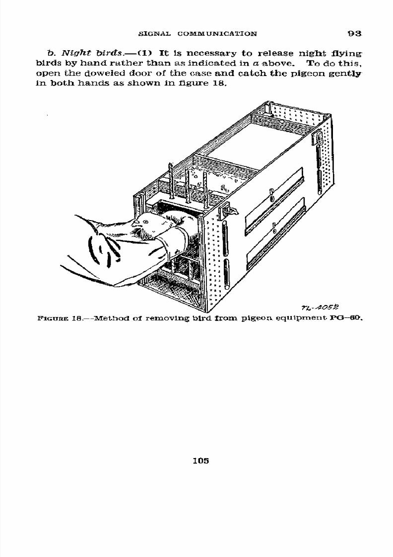
8/16/2019 (1942) FM 24-5 Signal Communication
http://slidepdf.com/reader/full/1942-fm-24-5-signal-communication 109/383
SIGNAL COMMUNICATION
93
b. Night
birds.-(1)
It is
necessary
to
release
night
flying
birds by hand rather
than as indicated
in a above.
To
do this,
open
the
doweled
door
of
the
case
and catch
the
pigeon
gently
in both
hands as shown
in figure 18.
FIGURE 18.-Method
of
removing bird Irom pigeon equipment
PO-60.
105
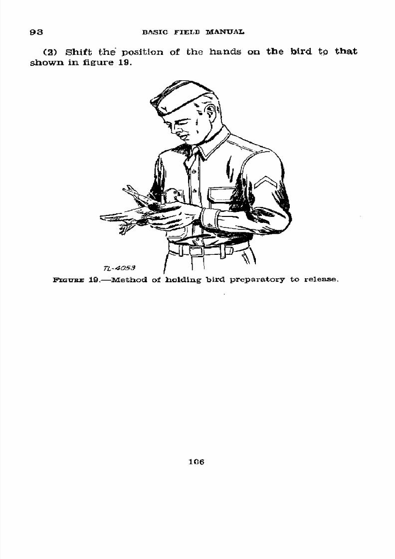
8/16/2019 (1942) FM 24-5 Signal Communication
http://slidepdf.com/reader/full/1942-fm-24-5-signal-communication 110/383
93
BASIC
FIELD
MANUAL
(2)
Shift
the position
of
the
hands
on
the bird
to
that
shown in
figure
19.
TL-4053
FIGVUR
19.-Method
of
holding
bird preparatory
to release.
106
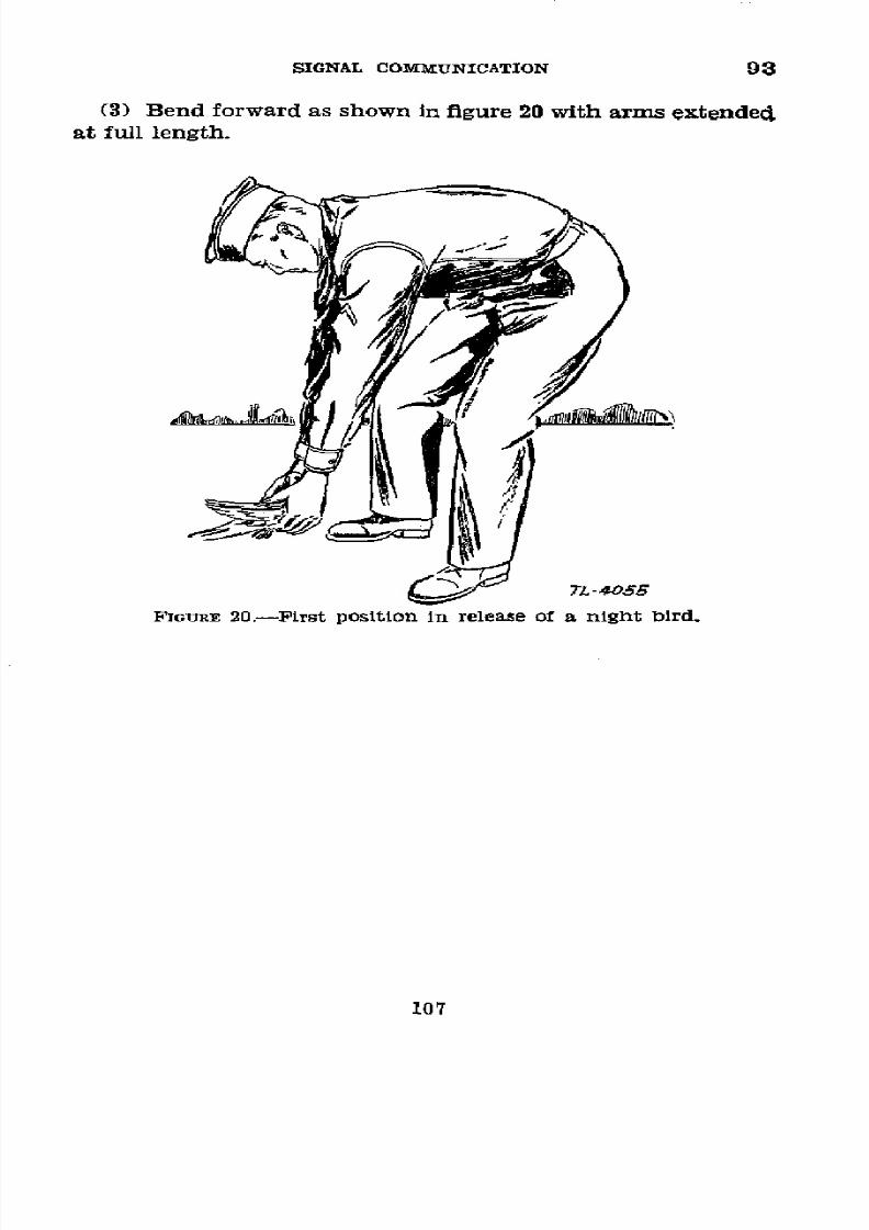
8/16/2019 (1942) FM 24-5 Signal Communication
http://slidepdf.com/reader/full/1942-fm-24-5-signal-communication 111/383
SIGNAL
COMMUNICATION
93
(3) Bend
forward
as shown
in figure 20
with arms
extended
at full
length.
TL-4055
FIGURE
20.-PFirst
position
in release
of a night
blrd.
107
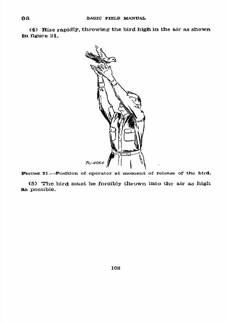
8/16/2019 (1942) FM 24-5 Signal Communication
http://slidepdf.com/reader/full/1942-fm-24-5-signal-communication 112/383
8/16/2019 (1942) FM 24-5 Signal Communication
http://slidepdf.com/reader/full/1942-fm-24-5-signal-communication 113/383
CHAPTER
5
RADIO
COMMUNICATION
Paragraphs
SE'rION
I.
General
-
-_________________________________
4-100
II.
Tactical
radio
nets-________________________ 101-108
III.
Operating
regulations_____
----------------
109-114
IV. Station
records___________------------------
115-120
SECTIoN I
GENERAL
U 94. RADIO SETS.-a.
A radio
set consists
usually
of
a trans-
mitter
for
sending out radio
waves
and
a
receiver
for
con-
verting radio
waves from other stations
to intelligible signals.
Radio
sets
are
broadly
classified
as
amplitude-modulated
(AM)
or
frequency-modulated
(FM),
and
as continuous-
wave (CW),
or as
tone-
or
voice-modulated.
b.
Amplitude
modulation
and
frequency
modulation
are
explained
in TM 11-455.
A significant
difference
so far
as
operation
in
the
field is
concerned
is
that
a
frequency-modu-
lated
receiver
responds
only
to the strongest
signal
being
re-
ceived
on any frequency
and therefore
the
presence
of
other
weaker
signals
cannot be
detected,
whereas an
amplitude-
modulated
receiver
reproduces simultaneously
all signals
re-
ceived
on the same
frequency
with resultant
interference, but
all
signals present
may be
heard
in the
background.
c.
Continuous-wave
signals
require the
generation
within
the
receiver
of
a
signal
to
be mixed
with
the
incoming signal
in order to
produce
an audible
sound, but provide
the sharpest
tuning
and
the
greatest
range
for
a
given
radio set.
In
tone
and
voice
modulation,
the transmitter
emits
a signal
which
is modified
by a
locally
generated
tone,
controlled by
a
key,
or
by a telephone
transmitter
so as to
convey
intelligence.
Both
continuous-wave
and tone-modulated
signals
are used
in
radiotelegraphy.
556773°-43--8
109
8/16/2019 (1942) FM 24-5 Signal Communication
http://slidepdf.com/reader/full/1942-fm-24-5-signal-communication 114/383
95
BASIC
FIELD
MANUAL
*
95.
DEFINITIONS.-Terms
as used
in
this
chapter
are
de-
fined
below.
For
definitions of
other
terms,
see
paragraphs
5 and
17.
a. Break-in
operation.-A
method
of
operation
wherein
the
receiving
operator
can
interrupt
the
transmitting
operator
at
any
time.
b.
Call
sign.-A
group
of
letters
and
numerals
or
a word,
used
for station
identification.
c.
Frequency
assignment.-The
frequency
or
frequencies,
usually
expressed
in
kilocycles
(kc)
or
megacycles
(mc),
at
which
the
station
is
authorized
to
operate.
For
sets
which
are calibrated
in
channels or
tuner settings,
this
assignment
is made
by
allotting
channels
or
tuner
settings.
d.
Headings.-The
heading
of a
message
is that
part
which
appears
before
the
text
begins.
(See
TM 11-454.)
e.
Intercept
station.-A
station
that
copies
enemy
radio
traffc
for
the
purpose
of obtaining
information
or
friendly
trafflc
for
the
purpose
of
supervision.
f. Internet
trafic.-Traffc
between
stations
which
are
not
assigned
to the
same
net.
g. Linking
station.-A
station
used
for
the relay
of
mes-
sages
from
one
net
to another.
h.
Mobile
station.-A
station
that
normally
operates
from
a
stationary
location
but
which
can be
rapidly
transported
to
another
location.
The
station
can be
operated
while
in
motion.
i. Number.-The
numbers
defined
below
should
not
be
confused
with
the
message
center
number
referred
to
in
chapter
2.
(1)
Station-to-station
serial
number.-A
number
assigned
by
an operator
to an
outgoing
message
to
facilitate
handling
and
checking of
traffic.
It
is
never
used
in the
abbreviated
form
message.
(2)
Writer's
number.-A
number
which
may
be
given
a
message
by
the
writer
and
which
is a part
of
the
text.
(See
par.
38a(6).)
j.
Net.-A
grouping
of
stations
on
one
frequency
for
pur-
poses
of
intercommunicating.
Usually
the
net
is
organized
to
follow
the
chain
of tactical
command-a
radio
station
at
110

8/16/2019 (1942) FM 24-5 Signal Communication
http://slidepdf.com/reader/full/1942-fm-24-5-signal-communication 115/383
SIGNAL
COMMUNICATION
95
the
superior
unit
and
radio stations
at
each of
its
immediate
subordinate
units.
(See
also
sec.
II.)
k.
Net
call
sign.-A
call
sign used to
call all
stations
in
a
net.
1.
Net
control station.-The
station
which
coordinates
and
supervises
the
stations within
the net
to assure
prompt
and
efficient
service to
the commander.
m.
Operator's
service-(1)
Receiving
service.-Station
from
which
received,
station-to-station serial
number,
receiving
operator's
personal
sign, and time
of receipt.
The time
of
receipt
appears
below the last
word
in the message.
The
bal-
ance
of
the
service
appears
at
the
top
of
the
message
blank.
(2) Sending
service.-Station
to
which
sent,
station-to-
station
serial number,
personal
sign
of
sending operator,
and
time sent. Example:
NR5 JX 2343.
n. Personal
sign.-One
or two
letters identifying
the
opera-
tor but
not necessarily
his
initials.
It
is never transmitted.
o. Portable
set.-A
radio set
which
can
be
carried
without
the
use
of
a
vehicle
and
operated
while in
motion.
p. Position-findinding
station.-A
station
containing
one
or
more
radio receivers capable
of
indicating
the
direction
from
which
incoming radio
waves
are arriving.
q.
Radiotelegraphy.-Radio
communication
by means
of
the
International
Morse Code.
r.
Radiotelephony.-Radio
communication by means
of
voice.
s.
Semimobile
station.-A
ground
station
which
is
trans-
portable
by a vehicle
but normally
operated
only from
a flxed
location.
t. Signal
operation
instructions.-See
paragraph
265.
u.
Station
log.-A chronological
record
of
traffic
and
unusual
events
kept at
a
station.
v.
Text.-That
part
of a message
between
the
break
sign
(BT)
and
the
suffix.
(See
TM
11-454.)
w. Time of
receipt.-That
time the
receiving
station
receipts for
a message.
x. Tralic.-All
transmitted
and
received
messages.
y. Transmission.-Complete
communication
between
sta-
tions.
z. Trick or
watch.-A tour
of
duty
as
an
operator.
aa.
Vehicular
station.-A
station
permanently
installed
in
111

8/16/2019 (1942) FM 24-5 Signal Communication
http://slidepdf.com/reader/full/1942-fm-24-5-signal-communication 116/383
95-97 BASIC
FIELD MANUAL
a
vehicle so that it
is capable of
operation with the vehicle
in motion.
* 96.
EMPLOYMENT.---a.
Radio is used
as
a
means
of
signal
communication for
tactical
control, for fire control, for
administrative purposes,
and for
liaison
between
and
within
all units to whom the
equipment is
available.
It
is essential
to
highly mobile elements such
as
aircraft and armored units,
and is especially applicable to motor movements and fast-
moving situations.
b.
Radiotelegraphy
is
the
normal
means
of
radio
commu-
'nication when distances
involved
are great and when, by rea-
son
of the subject matter and the
time
factor,
formal
mes-
sages in cipher and code
are required.
The International
M[orse
Code
is
used for
radiotelegraphy
by
the Army and
Nav.
(See
appendix III and FM
24-6
and TM 11-454.) In
combat
and
maneuver
zones where
radio
activity is curtailed,
it is desirable
to establish
radio nets
with
reduced
power,
dummy antennas,
etc.,
consistent with signal security regula-
tions for the
purpose of maintaining
radio operators at their
highest efficiency.
c. Radiotelephony is used when person-to-person com-
munication is required in the interests
of
speed and necessity
and when, by
reason
of the nature of the
communication
or
tfhe
time
factor
involved, secrecy is
relatively
unimportant.
In
general,
it
is
especially
suited
to
the
uses
of
forward
com-
bat
units for
communication
between airplanes,
between air-
planes
and the
ground,
between
vehicles
in motion,
between
vehicles and
ground stations, and with light portable radio
sets. The
use of
radiotelephony in
combat
requires
a
high
state of training and discipline
on
the part of individuals
con-
cerned
to
render transmission intelligible,
to avoid congestion,
and
to
provide
the
necessary signal
security.
d. Radio communication within a tactical
unit
on the
march may
be established at prearranged times
and
places
or between vehicular and mobile stations accompanying the
units and operating whiie actually on the march.
* 97.
CAPABILITIES.---a.
The range
of radio
communication
is,
in general,
independent of
conditions of roads and
traffic,
and is affected
by
the nature
of
the intervening
terrain in
112
8/16/2019 (1942) FM 24-5 Signal Communication
http://slidepdf.com/reader/full/1942-fm-24-5-signal-communication 117/383
SIGNAL
COMMUNICATION
97-98
a
varying
degree
depending upon the
frequency used.
Vehic-
ular sets, however,
are affected
by conditions
of roads and
traffic. Weather
conditions
may have a
serious
effect on
range.
(See
par.
99.)
b. Radio
communication is
the
most
effective means
of
signal
communication
between
rapidly moving
units
when
the
maintenance
of
wire
and messenger
communication
is
impracticable.
c. Radio communication can be readily
intercepted
and
interfered
with by
hostile
stations. It
is for
this
reason
that
emphasis
is
placed
on
encoding
messages,
as
prescribed
in
paragraph 49.
International
code is not
a form of cryp-
tography.
Strict discipline
is necessary
to
make
messages
short,
cryptic,
and
few in number
to avoid giving informa-
tion
to
the
enemy
and
unnecessarily congesting radio
chan-
nels.
(See
par.
112.)
d.
The
approximate
number,
types,
and
locations
of our
radio stations
can
be determined
by
hostile position-finding
stations.
From
this
information
the
enemy
can estimate
the
disposition
and
approximate
strength
of
our forces.
This
disadvantage
of radio
communication
can be
minimized by-
(1) Curtailing
the use of
radio
during
the
times
this
in-
formation
would
be of
most
value
to the
enemy.
(2)
Establishing
dummy
stations
to cause errors in his
deductions.
(3) Shifting the
location
of stations
frequently.
(4) Training
radio
operators in the strict
observance
of
radio discipline and radio
security.
(5)
Frequent
changes
and
limited
use of
call signs.
(6) Limiting
the
number
of stations in a
net.
(7)
Utilizing
low
power
when
possible.
e. Hostile
radio
stations can
interfere
deliberately with
our
radio communication
by blocking
a single frequency
or
band
of
frequencies.
The
enemy
may
also cause
our
stations
to
accept
false information
or
messages.
They
may also falsely
receipt for traffic
to
prevent reception
at
the
proper
station.
The effects of deception
can
be
minimized
by the use of a
frequently changed
authentication
system.
*
98. TRAINING
OF RADIO OPERAToRs.-See TM
11-450 and TM
11-454.
113
8/16/2019 (1942) FM 24-5 Signal Communication
http://slidepdf.com/reader/full/1942-fm-24-5-signal-communication 118/383
99-100
BASIC FIELD MANUAL
*
99.
LOCATION OF
STATIONS.-a. The
following
considerations
are important
in
the
location
of radio stations:
(1) Stations
should
be
in quiet localities,
protected
from
moisture
and
from enemy fire. The copying
of
weak signals
requires
great concentration by the operator.
Therefore,
noise and confusion in the vicinity of stations
should
be
minimized.
(2)
Stations
should be placed
at a
distance from
any source
of
radio
interference.
Sources
of possible interference are
power
lines, telegraph and
telephone
lines,
and
electrical
equipment
of
any
sort, including nearby radio
stations.
(3)
Radio
sets
wbich can
be
located
by
enemy position-
finding units should be located at least 200 yards or more
from
a command post
and
remotely
controlled
where
pos-
sible.
Also, it is unwise
to
have the sets placed
so they
in-
close
the
command
post, thus showing
the enemy the
definite
command-post
area.
b.
Radio
waves,
especially
those
of
high frequencies, may
be screened by intervening objects such as high hills, wooded
areas,
large
structures of
reinforced concrete
and steel, and
pole
lines carrying
conductors.
To minimize the effect of
such
screening,
the
radio station
should
have its
antenna
located in a
clear
space
and elevated when
practicable.
(See
par.
97a.)
However,
advantage
may be taken of
this char-
acteristic to screen
transmissions
from
the enemy. In
any
case,
the
item
of
antiaircraft
observation
must not
be
over-
looked.
* 100.
SPECIAL USES
OF
RADIO.-a. Radio is used
in
the mili-
tary
service for numerous special purposes, among
which
are-
(1) Reception.-(a) Position flnding
of enemy
radio sta-
tions on land,
ships,
or
aircraft.
(b)
Interception
of
hostile radio
traffic.
(c)
Interception
of
friendly
radio traffic for supervision.
(d)
Collection
of
upper-air meteorological
data
from air-
craft.
(2)
Transmission.-(a) Time
signals.
(b)
Press reports.
(c)
Counterpropaganda.
114
8/16/2019 (1942) FM 24-5 Signal Communication
http://slidepdf.com/reader/full/1942-fm-24-5-signal-communication 119/383
SIGNAL
COMMUNICATION
100-102
b. These
special services
are
operated
and maintained
by
Signal
Corps personnel
of the
higher
units,
usually
the
army.
c.
Copying
of press reports
is
a
function
of the
army signal
service
which
in
turn
rebroadcasts
to
the
lower
units.
SECTION
II
TACTICAL
RADIO NETS
U 101.
GENERAL.--a. Tactical
nets are
made up of mobile
or
vehicular
low-power
radio
stations
of tactical units
in the
field.
Tactical nets
are
given a
name indicative
of
the
su-
perior headquarters
in
the
net,
such
as the First Army net
or the 4th Infantry
Division Artillery net. (See
par. 106.)
b.
Nets operate either
on schedule
or continuously
(con-
tinuous
watch).
Nets operating
on schedule handle
trafflc
only
at
definite, prearranged times
and
in accordance with
a
prearranged schedule
of
intercommunication.
Nets oP-
erating
continuously
are prepared to
handle
traffic
at any
time; they
maintain
operators
on
duty
at
all stations
in
the
net
at
all
times. When practicable, messages relating
to
schedules will
be transmitted
by a
means of signal
communi-
cation
other than
radio.
c. All
stations in
a net
normally operate
on
the
same fre-
quency
or channel.
d. A
separate
frequency
or channel
for
each station
in
a
net
is
required
when duplex
operation
is
used,
that
is,
when
each station
is transmitting
and
receiving
simultane-
ously.
U
102.
CONTROL.--a. In.
every net one of the stations
is
desig-
nated as
the net control
station,
abbreviated
NCS.
The
NCS is
charged with
the clearing
of traffic within the net,
with dispatching internet
traffic
as quickly as
possible,
and
with
maintaining
order
within
the
net.
Questions
concern-
ing
traffic are referred
to
the NCS for decision.
The author-
ity
of the
NCS extends only
to
the
operation of
the net
and
its
discipline on the
air,
and is in no way concerned
with
the
interior administration
of any
station, nor
with
its
tactical
operation or movement.
Within
its
scope, however,
the
authority
of
the
NCS is
absolute, its
decisions
are
final,
115
8/16/2019 (1942) FM 24-5 Signal Communication
http://slidepdf.com/reader/full/1942-fm-24-5-signal-communication 120/383
102-104 BASIC FIELD
MANUAL
and its orders are
strictly obeyed.
These orders are gen-
erally transmitted
in
the
form
of
procedure
signals, or
mes-
sages, but may be contained in written orders,
circulars,
or
letters of instruction. (See par. 112.)
b. Duty
as
NCS is generally assigned to the station of
the
superior headquarters in
the net,
but may be assigned to
any station in the net which
can
best fulfill the duties.
All
other stations in the net are known as secondary stations
and are under control of the NCS.
c. A secondary station is
always
designated by the NCS
to
take
over
the
functions
of
the
NCS
if
the
NCS
leaves
the
net
for any
reason.
This station is called NC2.
*
103. OPERATION.--a.
A
net
may be operated as-
(1)
A
free
net, in
which
any station
can
communicate
with
any other station in the same net without first
obtaining
permission to do
so
from the NCS.
(2) A directed net,
in
which no station,
except
the NCS,
can
communicate,
except
for
the transmission
of
urgent
messages with any other station, without first obtaining the
permission of the NCS. Permission granted to a station
to transmit one or more messages includes all transmissions
necessary
to complete the transmission of such messages.
b. Nets
ordinarily are operated
free,
but the NCS may
change to
directed
net operation at any time if it
is unable
otherwise to maintain
proper
control.
In
a directed net,
traffic moves more
slowly
than
in
a free
net.
A
directed
net
should
be used only when
all
other means of
obtaining order
have
failed.
Free net operation is
resumed as
soon
as
the
necessity for
directed
net operation has
passed.
c. A
secondary
station always
informs the
NCS promptly
when it knows it
will
be unable
to follow
out its
schedules,
or unable to
have
its station on continuous watch at any
time
during
which
a
continuous
watch
ia
to
be
maintained.
(See
par. 101b.)
* 104. TRAFFIC.-a. Nets must be prepared to
assume
the
entire traffic load
of
their units
at
any time. For this
reason close cooperation with the message center is essen-
tial. Radio
stations
are
given
a
telephone
connection
when-
ever practicable and especially when they are remote from
the
command
post.
116

8/16/2019 (1942) FM 24-5 Signal Communication
http://slidepdf.com/reader/full/1942-fm-24-5-signal-communication 121/383
SIGNAL COMMUNICATION 104-106
b. A communication will not be interrupted until
com-
pleted
except as prescribed in paragraph
l9c.
When sta-
tions are
using
the break-in
system
of
operation,
communi-
cation
may be interrupted by
the
receiving operators.
c. Urgent messages are transmitted to the station of desti-
nation
or
to a linking
station
as
soon
as
possible,
under
the
restriction imposed
in
b above,
without obtaining
permission
from an NCS.
(See
par. 107.)
*
105.
ASSIGNMENT
OF
FREQUENCIES
AND CALL SIGNS.---. Radio
nets must
operate
on
assigned frequencies
to
prevent
inter-
ference with each
other and each radio
station must
be
iden-
tified by a
call sign.
Assignments of call signs and frequen-
cies are issued in
the
form
of signal
operation instructions.
(See par. 2651 for examples
applicable
to an infantry divi-
sion.) See FM 11-10 for examples of
division radio
net
charts.
b.
Changes in assignment of call signs and frequencies for
signal
security may
be expected by
radio nets in the
combat
zone.
These
changes
will
be
made
at
intervals
which
may
vary in length from several hours to several days.
c. The use of any call sign or frequency not assigned by
higher headquarters is prohibited.
C 106. ESTABLISHING
A
Nsr.-a.
During
the concentration
period,
station call signs,
net
call signs,
duties,
and
frequen-
cies are assigned to
the
various stations and nets. (See fig.
22.)
When time
permits, sets
in
the
net
should
be
calibrated
prior to the opening
of
the action.
b.
Radio
stations
conform
to the movements
of
the organi-
zations
served. As soon as
a station
is
set up and in
opera-
tion at the desired location it
endeavors to
report into
the
net of which it is a part.
c. The first station set up acts as NCS and the second sta-
tion
as
NC2
until
the
regularly
appointed
NCS
reports into
the net and takes control (par. 102). The NCS, when neces-
sary, causes each
new
station
reporting
into
the
net
to
adjust
its frequency
until
all
stations
can
be heard on the same
dial
setting
of the receiver
of the
NCS. The
NCS
may adjust its
frequency in accordance with directions from one of the
sec-
ondary stations
until that
station receives the
NCS and all
other stations
in the
net
on the same
dial
setting.
This
117

8/16/2019 (1942) FM 24-5 Signal Communication
http://slidepdf.com/reader/full/1942-fm-24-5-signal-communication 122/383
106-107
BASIC FIELD MANUAL
adjustment
of net frequency is made when
the third
station
reports
into the net
and
each station
reporting thereafter
with
an
incorrect
adjustment
is
caused
to
adjust
its
fre-
quency before it
transmits
any
traffic.
The NC2 takes
over
the
duties of
the
NCS
in case the
NCS disappears
from the
net
or leaves
the net without
giving
other instructions. Usually
7r3 (NCS)
2BOS,VCS)/T3
R3PT
9JG A4G A02
(,. ~371 . ~$R7r/
\ 37371 33R71
Net \
/
Aet
GT3 9L6
?L.7 474
iVJ
J13
CG9
zDC
FWGORE
22.-Tactical
radio
nets.
the first station of a net in a
numerical
or alphabetical se-
quence
of
call
signs, other than the NCS,
is
automatically
NC2 unless
some
other prearrangement has
been
made.
d.
Procedure
signals
are
provided
in
TM
11-454
and
FM
24-6.
* 107.
INTERÑET TRAFFIC.-a. Necessity.-Figure
22 may
be
considered
as
representing a
system
of tactical
nets.
The
nets 3PT and GT3 and the nets 3PT and 9LG are linked
physically
by having
two
stations at a
common
headquarters,
while the net
R02 is physically isolated. Consequently,
while
118
8/16/2019 (1942) FM 24-5 Signal Communication
http://slidepdf.com/reader/full/1942-fm-24-5-signal-communication 123/383
SIGNAL
COMMUNICATION
107-109
a message
originating in
the net 9LG with
destination in the
net GT3 could be
handled either by relay
through the net
3PT
or
by
direct
internet
communication,
all traffic to or
from
the
net
R02
must
be handled
by internet
communication.
b.
Procedure.-Exceptfor
the
transmission of urgent mes-
sages, a station
obtains permission
from
its
own
NCS
to leave
the net,
stating with
what
station
it is
going to
work, and
reports to
the
NCS of
the new net
before transmitting
any
traffic
in
that
net. A station reports back
into
its own
net as
soon
as its
business
is finished
in the
outside
net. If
the
station does
not
know the call
sign
of
the net or
of
the
NCS,
or
the
frequency
to be used, it obtains
such information by
means
other than radio, if practicable.
1 108.
RADIO
INTELLIGENCE-INTERCEPT
AND
POSITION
FIND-
ING.-a. Enemy
intercept
and position
finding
services can
easily
locate
our
transmitters. This can
be
minimized by
us-
ing the
least
practicable number
of
transmissions. Frequent
changes of
call
signs and frequencies
of
operation
will
confuse
the enemy intercept services
and cause them
to arrive
at
wrong
conclusions as to strength
of
our forces.
b. Position
finding is accomplished
by means
of
a cali-
brated directional
antenna
which
operates
a receiver.
By
reading the scale of
the antenna when the antenna
is
rotated
to
a
point of minimum
reception, the direction
from which
the
signal
is
arriving
can
be
determined.
If
two
or more
of
these
position-flnding
stations
located
at some distance
apart
take
simultaneous
bearings
on
the
same
signal, the
extensions
of
the lines
on the map,
indicating
the
direction
of reception,
wiIl intersect
at the
approximate
map location
of
the
trans-
mitting station.
(For
a detailed
discussion
of
the
theory of
position
finding
see FM 11-20.)
SECTION
III
OPERATING
REGULATIONS
U
109.
GENERAL.---.
References.-TM
11-454 and
FM
24-6,
cover operating
regulations.
Special
procedures
may
be
pre-
scribed
for such
purposes as
artillery fire
control,
command
nets
of
mechanized and
armored
units, command
nets of
air-
119

8/16/2019 (1942) FM 24-5 Signal Communication
http://slidepdf.com/reader/full/1942-fm-24-5-signal-communication 124/383
109-111
BASIC
FIELD
MANUAL
craft
in flight,
and
control
of
forward units
in
combat. Ex-
amples of
these special
procedures
are not included in this
manual;
they
are usually
brief,
and
are included
with
the
codes used for the special
purpose.
Other technical
manuals
or instructions cover the operation of specific items of equip-
ment. (See par.
4a,
and app. II.)
b. Handling
equipment.-Precautions or
the
transportation
of equipment given in paragraph 243 also apply to radio
equipment. When danger
of
capture exists,
radio
operators
should
be
prepared to render
the equipment,
authenticator
charts, and other
net
data
useless
to
the
enemy as
prescribed
in paragraph
14 or other instructions.
* 110. PROCEDURE,
PROCEDURE SIGNALS, AND PROCEDURE
SIGNS.-
a.
Definitions.-(1)
Radio procedure is
a
standardized routine
used by radio
operators in
the
handling
of
traffic.
(2) Procedure signs are nonsecret, arbitrary signals which
have
been
adopted to assist operators in handling
traffic in
the
shortest
possible
time.
Hereinafter
the
term
procedure
signs
will be
used to include
the terms "procedure
signs"
and
"procedure signals" defined
in TM 11-454.
b. Importance
of
procedure.-Strictcompliance
with oper-
ating procedures prescribed in TI 11-454 and FM
24-6
or
other special
procedures
insures the
accurate and rapid
handling of
traffic with minimum transmissions.
Every radio
operator
must
have
a
thorough
knowledge
of
the
correct
pro-
cedure
to use in any
particular
instance.
Deviations from
authorized
procedure
usually
results
in delaying traffic and is
prohibited.
*
111.
TRANSMITTING RULES.---. An operator will-listen
on
the
transmitting
frequency
assigned his
station
before making
any
call or other
transmission.
If there are other stations
working on
the
frequency he
will
not
interrupt
commúni-
cation unless such interruption is warranted by the class of
his traffic.
(See
TM 11-454.) All s*tations
remain silent
for
a period of 15 seconds at the completion
of each
message
transmitted, in order to
permit
any station in the net
to
send
traffic of
high precedence.
b. All transmissions must be as short and concise
as pos-
sible. No superfluous
calls
or
signals
of
any
kind will
be sent.
120
8/16/2019 (1942) FM 24-5 Signal Communication
http://slidepdf.com/reader/full/1942-fm-24-5-signal-communication 125/383
SIGNAL
COMMUNICATION
111-113
An operator
may test
his
transmitting
set
before
the
first
transmission
by
sending
a
few
"Vs"
followed
by his
own
station
call
sign.
c.
Messages
and
transmissions
must
be sent
at
a
speed
which
will
allow
the
receiving
stations
to
copy
them
on the
first
transmission.
Thus,
no transmissions
should
be faster
than the slowest
operator
in
a net
can
receive
them.
d. Particular
care is
necessary
that
all
call
signs
are made
slowly
and
distinctly.
e. The
procedure
sign
for
"Wait"
is used
when
an
imme-
diate
answer
cannot
be given.
J. Every
message
will
be terminated
with
a
suitable
proce-
dure sign.
*
112.
TRANSMISSIONS.--a.
Radio
stations
will
transmit
only
those
messages
authorized
by
competent
authority.
All
transmissions
and
messages
handled
will
be considered
as
official.
(See
par.
102a.)
b.
In
general,
the
need
for
inquiries,
instructions,
and
in-
formation
in connection
with
the
handling
of
traffic
is
ade-
quately
met
by
the
prescribed
procedure
signs.
When
procedure
signs
cannot
be used
a
service
message will
be
employed.
The
exchange
of
transmissions
in
other
than
authorized
form
is prohibited.
c. The
chief
operator
or
station
chief
of
a
station
has
full
authority
to
authorize
the
transmission
of
messages
relat-
ing
to
the
signal
service.
Such
messages
will
be
signed
with
the
call
sign
of the
station
of
origin,
and
will
be in
an
approved
code.
d. Every
operator
will
read
through
the text
of each
mes-
sage
filed
to ascertain
that
each
word
or the
individual
let-
ters
of
each
code
group
are
clear
and unmistakable.
If
there
is any
doubt
about
any
of
the words
or
letters,
he
will
have
them
verified.
*
113.
TIME
ENTRIES
AND
THE
RADIO
DAY.-Unless
otherwise
specified
by higher
authority-
a. Time
entries
on the
station
records
are
made
in the
tirne
of
the
zone
in
which
the
station
is located.
(See
par.
28.)
b.
Transmissions
involving
the
specifying
of
time
(time
broadcasts,
transmissions
as
to
the
time
a station
will
call
121
8/16/2019 (1942) FM 24-5 Signal Communication
http://slidepdf.com/reader/full/1942-fm-24-5-signal-communication 126/383
113-115
BASIC
FIELD
MANUAL
another
station or
return
to
a
net,
etc.) likewise
use the
time of
the zone in which
the station is located.
c.
The
"radio day"
is
the
24-hour period
covered
by
a
com-
plete set of
station
records.
It
commences
at
midnight
of
the time
zone
in
which
the station is
located,
and
ends
at
the following
midnight of the
same
zone.
All station
records
of
all
stations in
the
net will
be opened
and
closed
in
accord-
ance with
the
above-mentioned rule.
*
114. COOPERATION WITH
MESSAGE
CENTER.-The message
center
is the agency charged
with the receipt,
transmission,
and
delivery
of
messages, and with
the
encoding and decod-
ing of messages
when required.
It
is
therefore
the responsi-
bility of radio station
chiefs
to
keep the
message
center
informed
at
all
times
of
the stations
actually operating
in
the
net
and
of
traffic
conditions
with
reference
to
any
delay
time
that might occur to
messages routed by
radio.
SECTION
IV
STATION
RECORDS
U 115.
OPERATOR'S NUMBER
SHEET.-Stations
that
are
re-
quired to
use
station-to-station serial
numbers
(see TM 11-
454)
will
keep a
record of the numbers
in the
following
manner:
a.
On completion
of
a
period
of
transmission
or
reception,
the
key
operator
will
record
on
the
number
sheet
the
num-
ber or
numbers
of
the
messages sent
and the number or num-
bers of the messages
received. The
record
is made
by draw-
ing
a
line
through the numerals
in the
appropriate
column
assigned
to
the other
station
and
entering
the
time
of re-
ceipt
and his
personal
sign
in
the
blank
space
to the
right
of
the last
message
number
used during the period of
trans-
mission
and
reception.
b.
The
following
example
indicates a
completed
extract
of
a satisfactory number
sheet for
recording station-to-
station serial numbers:
c. Any messages
that
cannot
be sent without delay should
be
returned
to
the
message center for
routing by other
means.
Failure by radio station
personnel to
adhere
strictly
to directions
of
the
message center
or
other traffic
routing
122
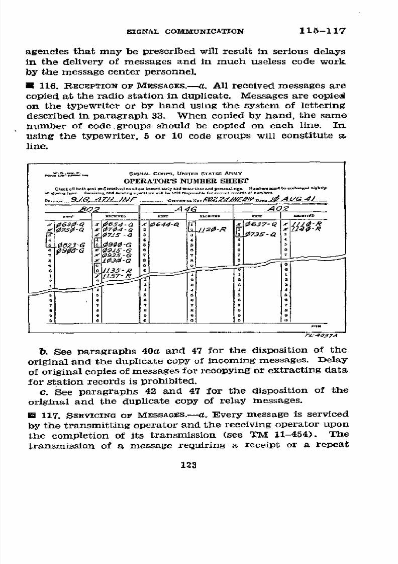
8/16/2019 (1942) FM 24-5 Signal Communication
http://slidepdf.com/reader/full/1942-fm-24-5-signal-communication 127/383
SIGNAL
COMMUNICATION
115-117
agencies
that
may
be prescribed
will
result
in
serious
delays
in
the
delivery
of
messages
and
in much
useless
code
work
by
the
message
center
personnel.
*
116.
RECEPTION
OF
MESSAGES.--a.
All
received
messages
are
copied
at the
radio
station
in
duplicate.
Messages
are
copied
on the
typewriter
or by
hand
using
the system
of lettering
described
in
paragraph
33.
When
copied
by hand,
the
same
number
of
code
groups
should
be
copied
on
each
line.
In
using
the typewriter,
5 or
10 code
groups
will
constitute
a.
line.
SIGNAL
CORPS,
UNITED
STATSM
RM Y
OPERATOR S
NUMBER
SHEET
Ci3= n bothont
tneICved
oumbr
toimmediy
d
e
tiL=.d penu
n.
Numbe.ymu
eceyb.sda.lghC
tyCOSinhour.
lyi.ing
nnd
diog
opnton
w~tbe hed3
po4sibleor eoy
t rords ofd umbe
. JGG.../.F
4C_
..
r
.......v ..
......
-..-.----------...-
...
l
y, 0
o
.
d4VG
A 2
_:063 Q
_
654
-Q1 i644-Q
1 0637-Q
1 R
d'1G
S'-G
5
e
b
d
SI0.3 -G
8
*l
il
l ]
] 0
9i
15y-R
b. See
paragraphs
40a
and
47 for
the
disposition
of the
original
and
the
duplicate
copy
of
incoming
messages.
Delay
of original
copies
of
messages
for
recopying
or extracting
data
for
station
records
is
prohibited.
c.
See
paragraphs
42
and
47
for
the
disposition
of
the
original
and
the
duplicate
copy
of
relay
messages.
,
117.
SERVICING
OF
MESSAGES.---.
Every
message
is
serviced
by
the
transmitting
operator
and
the
receiving
operator
upon
the
completion
of
its
transmission
(see
TM
11-454).
The
transmission
of a
message
requiring
a
receipt
or a
repeat
123
8/16/2019 (1942) FM 24-5 Signal Communication
http://slidepdf.com/reader/full/1942-fm-24-5-signal-communication 128/383
117-118
BASIC
FIELD
MANUAL
back
is
not considered
complete
until such
receipt
or repeat
back
is
received
by the
transmitting
operator.
b.
A
message
must
show
the
station
to
which
it
was
sent
or
from
which
it
was
received.
In any
case where
this
information
is
absent
from
the heading
of
the message
the
operator's
service
will
include
it.
c. The
sending
operator's
service
is
written
in
at the
bottom
of
the message
and
circled.
Many
operators
perform
this
service with
one hand
while operating
the
key with
the other.
(See par.
95m.)
* 118.
STATION LoG.-a.
General-(1)
A
station
log in
con-
junction
with
the
number
sheet
and
the file
of transmitted
and
received
messages forms
a complete
record of
events and
operating
conditions
which
occur during
a
radio day
at
a
station.
(2)
The amount
of
detail
that should
appear
upon
the
log varies
according
to the number
of
operators
on duty at
the station, and
the
state
of
training
of
the
operators,
but
the
keeping
of
the log should
not delay
traffic.
(3)
Signal
and communication
officers
are authorized
to
prescribe
the
amount
of detail
that they
require
on the
logs
of their
stations
but
the
following
essential
elements
with time
entry
for
each
will
be
included:
(a)
Operators
on
duty.
(b)
Opening
and
closing
of
stations.
(c) Causes
of
delays in
traffic.
(d)
Frequency
adjustments
and changes.
(e)
Unusual
occurrences
such
as procedure
violations,
veri-
fications,
etc.
(4)
During the
initial training
phases
the log
should in-
clude
all
signals
heard
or
transmitted,
thus
serving
as a
detailed
check
on
operating
procedures.
As
training
pro-
gresses
the
amount
of
detail
required
can
be gradually
reduced
to
the essential
elements
listed in
(3) above.
b.
Form
and
exampZe.-(1)
Training
form.-The
following
is
a satisfactory
station
log
form
for
use
during the
initial
training
period
and
for stations
having
a senior
(key) and
a junior
(log)
operator.
A
form
of this
kind
is desirable
when
actual transmissions
are
to
be logged
in
detail.
124

8/16/2019 (1942) FM 24-5 Signal Communication
http://slidepdf.com/reader/full/1942-fm-24-5-signal-communication 129/383
SIGNAL
COMMUNICATION
118
STATION LOG
Date ----------------
19----
Net
.-----------------------
Sheet
No.
.-.....
Station call
.-..- Net call
-.-------
Station
opened
.-.-
M
m
.-
.
...............
enior
operator
-----....
--.
Junior
operator
Time
To
From
Traffie
(2)
Example
of log.-During
the
later
training
period
and
in actual
field
operations
a
combination
form
having
the
operator's
number
sheet
printed
on
one side
and
a log printed
on the reverse
side
is more
satisfactory.
The
operator
merely
turns
his
number
sheet
over and
makes
the
log entry on
the
back
thereof
as the
events requiring
a
log entry
occur.
The
following
is
an
example
including
entries
of
such
a
form
in
common
use
at fixed
stations. This
form
is
printed on
the
reverse
side
of
the
operator's
number
sheet shown
in
para-
graph
115b.
SIGNAL
CORPS.
UNIuu
STAT^ ARMY
LOG
Bi~o.(,´ tA
a ....
t
.........
d .. t ..
.. 4-. L
96
Q G
OP/N
Ar
SELA1A
412#
Xc
6i5
REPOAr /W
TrO
B02
NCCS)
0¿R S/3S ZS34 A T 02
06& AX44G
]RJPORTS
/INNE7
06/3
4A02 JREPORATS
/
ANET
#8##
G Q
0G o
KrEY Q
70
GTEO RA7O
/
-Q
Ae PEL/ .V¿5S
G
/#
-7
PIEICIrvW
Q
0ro 4A
Y/CORDER
02
Eó
COSE
A
7/AT/ON
OR
/IOVB
556773-4056
556773°-43
9
125

8/16/2019 (1942) FM 24-5 Signal Communication
http://slidepdf.com/reader/full/1942-fm-24-5-signal-communication 130/383
119-120 BASIC FIELD MANUAL
* 119. DISPOSITION.-a.
The
station
log,
number sheets, and
any other records connected with the operation of a station
for
a radio
day
will
be placed together
in
a
packet as soon
as
possible after the conclusion of such period and plainly
marked
with
the date and a description of contents. These
records
will be
disposed of as
prescribed
by the unit signal
or
communication
officer.
b. Radio station records often contain
valuable
informa-
tion
for the enemy intelligence service. If at any time there
is great danger of station records being captured by the
enemy,
they
must
be
destroyed.
U
120. IMPoRTANCE.-a.
Station records
are
valuable
studies
for signal and
communication
officers
to use in
determining
errors
made
by
operating personnel,
causes
of
delays in traffic,
and in determining the proper actions necessary
for
increas-
ing traffic
efficiency. They are also useful in the recovery
of
lost
messages
and
as
verification records.
b.
The
keeping
of
these
records
is
secondary
to
the
primary
mission
of
delivering the message to the addressee without
delay and
exactly
as written by the writer. Operators should
be
constantly reminded of
their
primary
mission.
126
8/16/2019 (1942) FM 24-5 Signal Communication
http://slidepdf.com/reader/full/1942-fm-24-5-signal-communication 131/383
CHAPTER
6
VISUAL COMMUNICATION
Paragraphs
SECTION I.
General ____________-________________________
121-122
II. Lamps _______________________________________
123-130
III.
Flags
_______________________________________
131-136
IV. Pyrotechnics
_________________________________ 137-142
V.
Panels__________________________________143-155
VI.
Airplane maneuvers
as
signals_______________
156
SECTION
I
GENERAL
*
121.
SCOPE.-Visual
communication includes all
signals
re-
ceived
by the eye regardless of
how
they may have been trans-
mitted. While arm and hand signals are properly a part of
visual
communication,
they
are
not included
in this manual
but
are prescribed in
other
training
publications.
In this
manual visual
communication
includes only communication
by
lamps, flags,
pyrotechnics, panels and
airplanes.
*
122.
CAPABILrTIES
AND
EMPLOYMENT.-a.
General.-In
areas
served
by
other signal communication equipment, visual
com-
munication is an auxiliary
means
supplementing wire and
radio, but
the
necessary
equipment
issued
for
its
use
should
always
be
at hand and in operative condition if, due to the
failure
of
other means, the condition
necessitating
and favor-
ing
its
employment
should
arise.
It may be used to supple-
ment
one-way
radio communication.
For
example, where a
forward command
group
is
able to
receive
messages
by
radio
but
not to transmit, the higher commander may direct that
the reply be
sent
by
means
of visual communication. For
small
isolated groups or
those which are not organically
equipped
with technical
means of signal communication, the
situation
may
sometimes be
such
that
visual
signaling with
any
means
available Is
the only method possible.
Its use
depends upon
the
type
of
warfare, proximity
of
the
enemy,
127

8/16/2019 (1942) FM 24-5 Signal Communication
http://slidepdf.com/reader/full/1942-fm-24-5-signal-communication 132/383
122
BASIC
FIELD
MANUAL
terrain,
and
weather.
While
the
relatively
slow
speed
of
transmission
renders
visual
signal
communication
less
suited
for
transmitting
long
messages
than
other
means
usually
available,
it
is well
adapted
to transmitting
prearranged
mes-
sages
and
code groups
such
as
those
used
in
the
Air-Ground
Liaison
Code or
the
Division
Field
Code, using
either
groups
of
letters
or numerals
in
brief
messages
over
short distances.
This
type
of visual
signaling
is especially
applicable
for use
from
front
to
rear,
from
ground
to air,
and from
ground
to
a
vehicle
in motion.
The
success
of
visual
communication
depends
upon
training,
previous
preparation and distribution
of
codes,
and
prearranged
messages.
The
degree
of
training
which
personnel
require
depends
upon
the
purpose
for
which
they
will
be
employed.
For
short-range
communication
to
extend
tactical
control
below
the
forward
limit of
the
more
technical
means,
a
very
modest
degree
of
training
of a
suffi-
cient
proportion
of
individuals
to
insure
that
at
least
one man
with
each group
the
size
of
the
squad
is
trained
will
produce
important
results.
The ability
to
transmit
and
receive
groups
of
numerals
can
be acquired
by
a
soldier
of average
intelli-
gence
in
a
short
time.
b.
Between
ground stations.-(1)
Making
contact.-When
a visual
signaling
system
has
been
installed,
or
when
for any
other
reason
visual
signals
may
be
expected,
all likely
points
from
which such
signals
might originate
should
be examined
frequently
to
see
if
visual
signaling
is being
attempted.
At-
tempts
to
attract
attention
of
personnel
with
whom
com-
munication
is desired
must be
persistent.
The azimuths
of
all prepared
stations
with
whom visual
communication
is
expected
should be
recorded
and
stakes
properly
alined and
tagged with the
designation
of the
unit with
which they
are
concerned
placed
in the
ground
to mark
the line
of
sight
to
the
other
visual
stations. Por
light
portable
equipment
car-
ried
by
forward
groups or
detachments,
the
distances
in-
volved
will
usually facilitate
attracting
attention
through
some
prearranged
sound
or
visual
means.
All personnel
must
be
trained
to be
on
the
alert
for
such signals
and
to direct
the
attention
of
the proper
personnel
to them.
(2)
Limitations.-If
other
effective
means
are
available,
visual
communication
should
not
be
used when
it
is likely
128

8/16/2019 (1942) FM 24-5 Signal Communication
http://slidepdf.com/reader/full/1942-fm-24-5-signal-communication 133/383
SIGNAL
COMMUNICATION
122
to disclose
a
position or
to draw fire on
other troops. Where
signals
being sent
are likely to be
seen
and read by
the enemy,
care
must
be
taken
not to
disclose
information
which
may
enable the enemy
to take
countermeasures
in view
of
the
time factor
involved.
In
general,
the time
factor favors more
extensive
use of nonsecret
means between the smaller
for-
ward elements.
Great
care must be exercised in
the
selection
of locations
for visual signaling
stations,
especially those
transmitting
from rear
to front.
These
considerations
there-
fore
frequently
preclude two-way
visual communication.
When
not
in
immediate
contact
with
the
enemy, visual
sta-
tions may
communicate
in any
direction
but
in
immediate
contact with
the enemy,
visual communication
will generally
be employed
only from
front to rear
although
two-way
lat-
eral
communication
may be
employed
if
both stations are
defiladed
from hostile
view.
(3)
Acvantages.-The advantages of
visual
communication
between ground
stations
are-
(a)
Rapidity with
which
stations
can be installed.
(b) Speed
with
which short messages
and
prearranged
signals may be sent.
(c)
The light weight, simplicity, and
portability of
the
equipment.
(d) Absence of
need for metallic
circuits
between
stations.
(e) Independence
of intervening terrain or
zones
under
hostile
fire
as
compared
to
wire
or
messenger
service, as
long
as mutually
visible
stations exist.
(4) Disadvantages.-Disadvantages
of visual
communica-
tion
between
ground
stations
as
compared
with
wire
and
radio are-
(a)
Slowness, hence poor adaptability
for
sending
long
messages.
(b)
Dependence
on
mutual
visibility.
(c) Difficulty of locating
companion
station, attracting
its
attention,
and insuring receipt
for
traffic.
(d) The vigilance
necessary
by operators
to
avoid
missing
signals.
(e)
Limited
range.
e.
Air-ground
communication.-Visual
communication
from the
ground
to
airplanes
in
flight is
possible
by use of
129
8/16/2019 (1942) FM 24-5 Signal Communication
http://slidepdf.com/reader/full/1942-fm-24-5-signal-communication 134/383
122-123 BASIC FIELD MANUAL
panels,
pyrotechnics,
flags,
and signal
lamps.
The airplane
may
reply
by radio, dropped
message, pyrotechnics,
lamps, or
limited wing
signals, all
of which are covered
elsewhere in
this manual.
(1)
Advantages.-The
advantages
of visual
air-ground
communication
are the same
as
those listed
in b(3) (a),
(b),
and
(c)
above.
(2) Disadvantages.-The
disadvantages
of visual air-
ground communication
are-
(a)
Impracticability
of
sending
long messages.
(b)
Dependence
on
vlsibility.
(c)
Air observer's
difficulty locating stations
desired.
(d)
Ease
with
which hostile aircraft can
locate ground
stations.
SECTION II
LAMPS
*
123. EQUIPMENT.---a.
Signal lamp
equipments EE-6,
EE-6-A,
EE-10-B,
and
EE-84 are authorized
for specified
field
artillery and
coast
artillery
units.
Signal lamp
equip-
ment
EE-80
is
a
portable searchlight
12
inches in diameter
mounted
on a tripod.
It
is normally placed in airdrome
control
towers and used for signaling to airplanes.
b.
The
EE-6
and EE-6-A
are essentially the same,
the dif-
ference
being
that
the
EE-6-A includes
a
belt
with
an
at-
tached
case and a control
box for carrying the eight
dry
batteries,
spare bulbs,
and key,
while
in the EE-6 these items
are carried in one case rested
on the
ground
during
operation.
Both
consist
of
a portable electric
lamp
with
a metal
reflector
14
centimeters
(about
51/2 inches)
in
diameter,
a
sighting
tube
on the top, a
hinged
lid
covering
the front,
and
a two-
wire cord
to
connect
the
batteries
and
lamp.
Lamp
signal-
ing
is accomplished
by operating
the key to cause
short
or
long
flashes of the
lamp. These
flashes
combined make
the
characters
of the International
Morse
Code. (Other
lamp
signals are described in par.
136.)
c. The
EE-10-B
uses
either a
6-volt, a-c supply
from a
110-volt
step-down transformer
or a 6-volt
battery
supply.
.It is
heavier
and more
rugged
than
the EE-6 and has
a
130
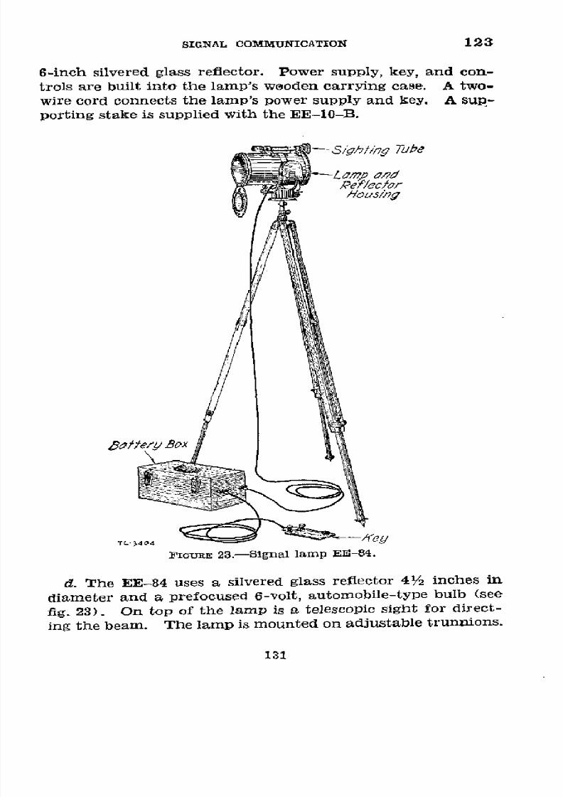
8/16/2019 (1942) FM 24-5 Signal Communication
http://slidepdf.com/reader/full/1942-fm-24-5-signal-communication 135/383
SIGNAL
COMMUNICATION
123
6-inch
silvered
glass
reflector.
Power
supply,
key,
and
con-
trols
are
built
into
the
lamp's
weoden
carrying
case.
A
two-
wire cord
connects
the
lamp's
power
supply
and
key.
A
sup-
porting
stake
is supplied
with
the
EE-10-B.
:¡hting
Tuke
aLm£
a1d
Rel/ec/or
Housing
ttfery
Box
TL3-404
FIGURE
23.-Signal
lamp
EE-84.
d.
The
EE-84
uses
a
silvered
glass
reflector
41/2
inches
in
diameter
and
a
prefocused
6-volt,
automobile-type
bulb
(see
fig.
23).
On
top
of
the
lamp
is
a
telescopic
sight
for
direct-
ing
the
beam.
The
lamp
is
mounted
on
adjustable
trunnions.
131

8/16/2019 (1942) FM 24-5 Signal Communication
http://slidepdf.com/reader/full/1942-fm-24-5-signal-communication 136/383
123-124 BASIC FIELD
MANUAL
This assembly
is
mounted
on a
standard
aiming circle
tripod
to permit laying
the lamp from
a
map.
A 5-foot,
two-wire
cord
connects
a
metal
box
containing
dry
batteries and a
relay
to the lamp. The key
is connected
to this box
by a
longer two-wire
cord and hence
may
be located
some
dis-
tance from the lamp.
Sighf/tng
point
Distance
between
cenfers of the
reflector
and
the sighting
tube.
Center //lght
spof on
thisnter-
seoi1on
which is
fhe
same
heighf
above
the
round
as
the
center
of
the ref7ector,
TL-1713
FIGURE
24.-Adjustment
of
signal
lamp
equipment
EE-6.
*
124. ADJUSTMENT.-The
reflecting
apparatus
of
all lamps
should be checked
for
adjustment at frequent
intervals and
each
time a bulb
is replaced. To
adjust
the EE-6,
draw
horizontal
and
vertical
lines
on a
flat
vertical
background
132

8/16/2019 (1942) FM 24-5 Signal Communication
http://slidepdf.com/reader/full/1942-fm-24-5-signal-communication 137/383
SIGNAL COMMUNICATION
124-127
like a wall, intersecting
at
the height
of the
reflector
above
the ground (see
fig. 24).
Locate
a
sighting point
on
the ver-
tical
line a
distance
above this
intersection
equal to the dis-
tance
between
the
centers
of
the
reflector
and
the sighting
tube. Set up
the
lamp
a few
yards
away and
aim
the sight-
ing tube
at
the sighting
point.
Turn the
reflector
screws
supporting until the concentrated
light
spot
becomes
cen-
tered
on the horizontal and
vertical
lines. A similar proce-
dure
may
be followed
in adjusting other
lamps. When
prop-
erly adjusted, the lamp
projects a beam of approximately
parallel light
rays.
Accuracy
in
this adjustment
restricts
the
area
in which
signals
may be observed and increases
the
range.
U
125.
CARE.-The following
precautions are
necessary
in
handling
and operating lamps:
a.
The
lid
should be closed when
the lamp is not
in use.
b. The
reflector should
not
be
touched with the fingers,
and
should
be
cleaned
only
with
clean
gauze
or
cotton damp-
ened
with
clean
water or
alcohol.
c. Cord connections
should be
kept
clean and tight.
d. The lamp
should
not
be
used for illumination.
* 126.
TRAINING.-Lamp..operators
should be qualified
in the
following:
a. International
Morse Code. (See app. III.)
b.
Lamp
procedure,
lamp
sighting and adjusting.
c. Use of field
glasses,
compass,
and map reading.
d. Distance
limitations
of the lamp.
e.
Establishment,
operation,
and maintenance
of
visual
stations.
f. Fire-control
Code.
*
127.
INSTALLATION.---a. Location.-Under favorable condi-
tions
the
EE-6
has
a range
of
3,300
yards in daylight
or
6,000
yards
at
night. (See b
below.)
The ranges of
other types
are
greater.
Ordinarily
the
white bulb
is
used. The
red bulb
is
preferable in
operating
through
smoke or
fog. Shadows,
reflections, and background affect the visibility of
the beam.
In
daylight
place the lamp
in a deep shadow. Sunlight
fall-
ing on
the
face of
the
lamp produces
a
reflector glare
making
133
8/16/2019 (1942) FM 24-5 Signal Communication
http://slidepdf.com/reader/full/1942-fm-24-5-signal-communication 138/383
127-129
BASIC
FIELD
MANUAL
signals
unreadable.
It
is essential
that the
lamp
be accu-
rately
sighted
on
the receiving
station.
Slight
movements
of
the
lamp divert the
beam
and
the
signal becomes
faint or
invisible.
Therefore,
some
form
of fixed
mounting
must be
used.
b.
Improvisations.-(1)
Stability
may
be
obtained by
fixing
the lamp to
a tripod like
that issued for
use with the
pris-
matic
compass
or
commercial
cameras.
A
stake driven
in
the
ground
may
be
used.
Operation
may
be improved
by
pro-
viding a battery box
for
the batteries
and
spare lamp bulbs,
and
mounting
a
telegraph
key on
a
removable
cover.
When
operating
many
lamps at
night in
the
same general
area,
it
is
desirable
to
use
colored
bulbs.
(2)
In
permanent
and
semipermanent
stations,
lamps
may
be oriented
and fixed
in position.
Beam diffusion,
increasing
the possibility
that
signals may
be
read by
the enemy,
may be
minimized
by
using
a wooden
tube
6
to 9
feet
long,
approxi-
mately
the
size
of
the
lamp
at
the inner
end
and tapered
slightly
to a smaller
size at the
outer end.
U 128.
INTERNATIONAL
MORSE CODE.-The
alphabet,
numerals,
and special
signs
transmitted
in
International
Morse
Code
are
shown
in
appendix III.
U
129.
MESSAGE TRANSMISSION.---a.
The speed
of sending dots
and dashes
should
be constant.
Speed of
transmission
is in-
creased
by
decreasing
the
intervals
between
successive
dots
and
dashes,
then
letters,
and finally,
words.
(1)
A dot
is a short
flash
of
about
½/2econd.
(2) A
dash
is a
long
flash of about 11/2
seconds.
(3)
The
maximum
interval between
successive
dots
and
dashes
should
be about 1/2 second.
(4)
The maximum
interval
between
successive
letters or
characters
should
be
about
11/2
seconds.
(5) The maximum interval
between successive
words
should
be about
3
seconds
unless it is
necessary for
the
re-
ceiving station
to acknowledge
by
one
or two dots
after each
word,
in which
case
the
transmission
is
resumed
immediately
upon receipt
of such
acknowledgment.
(See par.
130.)
b.
In order that lamp
signals
may be easily read it is essen-
tial
that
they be sent
slowly.
Experienced
operators
should
134
8/16/2019 (1942) FM 24-5 Signal Communication
http://slidepdf.com/reader/full/1942-fm-24-5-signal-communication 139/383
8/16/2019 (1942) FM 24-5 Signal Communication
http://slidepdf.com/reader/full/1942-fm-24-5-signal-communication 140/383
130-131
BASIC
FIELD MDANUAL
series of dots may also be
used by
the calling station
in
place
of
a call to
attract
the
attention
of the
called station after
communication has
been
established.
(4) RL-Resight
your lamp, signals
are
dim.
(5) A series of dashes
of
increasing
length-Your
adjust-
ment is improving.
(6) A very long dash or steady light-Your adjustment is
satisfactory.
(7)
A series of
dashes
of decreasing
length-Your
adjust-
ment is
becoming
worse.
(8)
R-Entire
message
received.
(9) MU-Move
up.
(10)
MD-Move down.
(11)
MR-Move
right.
(12) ML-Move left.
e. Acknowledgment.-Every
message
which
has
been re-
ceived will
be acknowledged by some means even though diffi-
cult. In general,
lamps
will
be used
only
from front to
rear,
and the
acknowledgment
in such cases
will
be
made from the
rear station by
pyrotechnics
or some means other than lamp
or
flag,
if such
use would divulge the
location
of the rear
sta-
tion
to
the
enemy.
This
is
important
since
rear stations are
normally located at or
near
command or observation posts,
and this
intelligence
may draw artillery fire. Situations will
occur, particularly within
the
infantry
and
field artillery
battalion
during
open
warfare,
when
two-way
lamp
signaling
is feasible without enemy observation. Then acknowledg-
ment may be
made
by
lamp.
If the
letter F
precedes
the
transmission, the receiving station
acknowledges
the
receipt
of the message
by
some means other than flag or lamnp.
Otherwise the receiving station may acknowledge
each
word
with
either one
dot or two
dots,
depending upon
whether the
word was Understood or not.
SECTION
MI
FLAGS
E 131. GENERAL.-Suitable flag equipment
is issued
for
sig-
naling
by
semaphore
and
wigwag,
and
for
special
purposes.
136

8/16/2019 (1942) FM 24-5 Signal Communication
http://slidepdf.com/reader/full/1942-fm-24-5-signal-communication 141/383
SIGNAL COMMUNICATION 131-135
If no standard
equipment
is
available,
strips
of
cloth
tied to-
ward
the outer
end
of sticks of wood
or
bayonets
will
serve
for flags. For short
ranges,
when
the use of flags
would be
unduly
conspicuous,
the
hands
or arms,
or
the
headdress
or
handkerchiefs
held in the hand
may
be
used.
E 132.
CÁRE.-Signal flags
should
be kept in a
clean,
service-
able
condition.
A
clean
flag
can
be
more easily read.
*
133.
TRAINING.-The
steps
to
be followed
in training
of flag-
men
are
in general identical to those
given
in
paragraph
126
for
the training of lamp operators. The
semaphore flag-
men
use the
semaphore
code. (See
fig.
25.)
A proficient
semaphore flagman should
be
able to transmit and receive
at the rate of
125
characters
per
minute at medium
ranges.
Flagmen
are
trained
to
transmit in the kneeling, sitting,
or
prone
position.
Wigwag
signalers,
which include
those
equipped
with
sets
consisting
of a single
flag and staff,
use
the
International
Morse Code (see
app. I).
U
134.
USE.-a. Flag
signal
ranges vary with
the
location
of
the stations, visibility, and the proficiency of the flagmen.
Under
favorable conditions
and with the
aid
of fleld glasses,
semaphore
flags can be
read up
to
2,500
yards.
b.
The background should
be
the
same
for
all positions
of
the
flags during the
transmission
of
a
message.
The
flag
color should contrast
with
the color of the
background.
c.
When
a
station
is
moved
to
get
a
better
background,
the
flagman at
each station
holds his
flag
vertically
above
his
head. The station requesting the move lowers its
flag imme-
diately when the flagman
of
the moving
station
arrives
at
a
position
having
a suitable background.
d.
When
signal
flags
are used under
hostile small arms
fire,
distances
will be short and effective
ranges
will depend on
cover for
the
flagmen. The rear station
will
permit the for-
ward
station
to
select
the
most
advantageous
position
and
the
rear station
conforms.
I
135.
SEMAPHORE
FLAG PROCEDURE
AND
TRANSMISSION.--a.
The
semaphore
code is given
in figure 25. The "end
of mes-
sage"
signal (chop-chop)
is executed by
waving
both flags
in short
vertical opposite
directional
arcs on
the left
side of
the
body.
137

8/16/2019 (1942) FM 24-5 Signal Communication
http://slidepdf.com/reader/full/1942-fm-24-5-signal-communication 142/383
135-136
BASIC
FIELD MIANUAL
b.
The semaphore
flag signaling
call to one station consists
of the signal
"attention."
Otherwise, the call is that
given
for
lamps
in
paragraph
129.
The
special
signals
and mean-
ings
used in semaphore flag signaling are'shown in
figure
25.
U 136. WIGWAG
PROCEDURE AND
-TRANSMISSION.-a. For general
use in
lower
units
wigwag
signaling
is more
applicable
than
semaphore
as transmission
is
possible
with improvised equip-
ment
and
does not require an operator
to expose
himself
by
standing.
Since wigwag
flags, radios, telegraphs, and signal
lamps
employ
the
International
Morse
Code
(app.
II),
train-
ing is facilitated.
It is especially
suited to transmission
of
code groups
consisting
of
numerals, which are
provided
in
certain
codes.
In
the
absence of
suitable
codes, prearranged
numerals may be substituted.
Training must include the
transmission
and reception
of
wigwag signals in
the
kneeling
and prone positions
as well
as standing.
b. A dot
is
made
by
a motion from overhead downward
to
the
sender's right,
through an
arc
of
90
°
in
the
plane
per-
pendicular
to the line of transmission,
and returning
imme-
diately to the starting
point
overhead. A
dash is
made
by a
similar motion
to the
sender's
left.
A
short
pause
in
the
vertical position
indicates spacing between the
individual
characters. The
end
of
a
word
or
group
is indicated
by dip-
ping the flag
to
the
operator's
front;
the
end of a message is
indicated
by
two
such
motions.
c.
A
hand
lamp may
be substituted
for
the flag. When
using a hand lamp, the swing may
be upward from a starting
point with the arm hanging
down
naturally, instead of down-
ward from a starting
point overhead.
d. The procedure
prescribed in paragraph
130 shall be
fol-
lowed except
that
the ATTENTION sign, made by waving the
flag
through 180
°
overhead
several
times,
or by
waving the
lantern
through 180
°
across
the
knees,
may
be
used
in
call-
ing;
and that the
ANSWERING
sign may be used in
answer-
ing
a call as
well
as in "receipting"
an item
transmitted.
If
an answering
signal is not received, and if
the
message is
urgent, the
operator transmits the message several times
until he is reasonably sure that the message has been received.
e.
Por
communication with
aircraft, the wigwag
operator
faces
the
airplane
continuously
while
transmitting, turning
138

8/16/2019 (1942) FM 24-5 Signal Communication
http://slidepdf.com/reader/full/1942-fm-24-5-signal-communication 143/383
SIGNAL
COMMUNICATION
136
B9
~~
~~~~
~8
~~AEN
Z
ON
3
3
9
9
u
D
4
J
V
EIED, SN OFW E 5A
RECEIVED
OR
END
OF
MESE-
GO4HEAD
X
<
r
FIGURE
25.-Semaphore
code.
his body
for
such
purposes.
Such
messages
may
be
trans-
mitted
in the
clear
under
proper
conditions,
or groups
of
let-
ters
or
numerals
prescribed
in
the air-ground
liaison
code
may
be
used.
For
low-flying
aircraft
this
means
is
sometimes
faster
and
more
practical
than
a
series
of
signals
by
panels.
Under
exceptional
conditions
the
wigwag
method
of
trans-
mission
may
be
employed
by
Dersons
in a
slow-flying
aircraft
or
in
a
moving
vehicle.
139
8/16/2019 (1942) FM 24-5 Signal Communication
http://slidepdf.com/reader/full/1942-fm-24-5-signal-communication 144/383
137
BASIC
FIELD
MANUAL
SECTION IV
PYROTECHNICS
U 137
EQuPMENT.-Pyrotechnic
devices
used
for signal
com-
munication
are the
ground
signal projector,
the
pyrotechnic
pistol,
aircraft,
and
the Very
pistol.
a.
Ground
signal
projectors.-There
are
three
types
of
ground
signal
projectors.
In all
types
the
barrel
is
about
12 inches
long
and
has
a 42-mm
bore.
(1)
In
projector
M1 a firing
pin
is centered
in the
bot-
tom
or
breech end
of
the
tube
and
is
actuated
by a
simple,
springless
hammer
and
lanyard.
For firing,
this
projector
is
mounted on
the
muzzle
of the
service
rifle
or on a steel
supporting tube,
about 4
feet
long, with a flange
and sharp
pin
at
one end
to be pushed
into
the ground.
(See
fig.
26(.)
The
signal cartridge
resembles
a large shotgun
shell without
the
flanged
base. It
is dropped
into
the muzzle,
base
first,
and
then
fired by
a quick
jerk on
the
lanyard.
After
each
discharge,
the projector
must
be
inverted
to
dislodge
the
cartridge
base.
The
cartridge
contains
varying
types of
signals,
which are
projected about
300 feet upon
being fired.
(See
fig.
260.)
(2)
The projector
M3
(fig.
260)
has
a
fixed
firing
pin
in
the bottom
or
breech
of
the
bore.
This
type fires
the
same
ammunition as
the first type
projector. The
signal car-
tridge
is
dropped
into
the
muzzle,
base
first,
and
allowed
to
slide down
the tube
until
it
is stopped
just
above the
firing
pin
by
a
spring
arrester.
To
fire
the
cartridge the
operator
assumes the prone
position, the tube
being held
muzzle
up at arm's length
a
few inches
from
the
ground;
then
the breech
end is struck
smartly against
the
ground.
The inertia
of the
cartridge causes
it to
pass
the
arrester
and
strike against
the
firing
pin,
thus
igniting
the
propelling
charge.
After
discharge,
the
projector
must
be
inverted
to
dislodge
the cartridge
base.
(See fig. 260.)
(3)
The
projector
M4 is a
modification
of
the M3 and
differs
very slightly
in mechanical construction
or
physical
appearance.
(See fig.
260.)
It
is fired
in the same manner
as
the
M3 and
uses the
same
ammunition.
b.
Pyrotechnic
pistol.-The
pyrotechnic
pistol,
aircraft
type,
is
for
use
in
airplanes.
It
consists
of a
heavy
frame
140
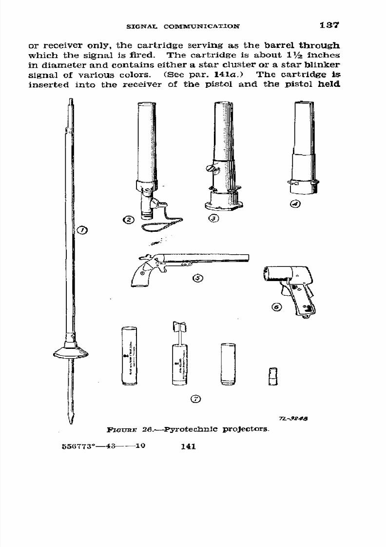
8/16/2019 (1942) FM 24-5 Signal Communication
http://slidepdf.com/reader/full/1942-fm-24-5-signal-communication 145/383
SIGNAL
COMMUNICATION
137
or
receiver
only,
the
cartridge
serving
as the barrel
through
which the signal
is
fired.
The
cartridge is
about
11/2 inches
in
diameter
and contains
either
a
star
cluster
or
a star
blinker
signal
of
various
colors.
(See
par.
141a.)
The cartridge
is
inserted
into the
receiver
of the
pistol
and the
pistol held
7Z-59244
FiGuRE 26.-Pyrotechnic
projectors.
556773°-43
10
141

8/16/2019 (1942) FM 24-5 Signal Communication
http://slidepdf.com/reader/full/1942-fm-24-5-signal-communication 146/383
137-139
BASIC FIELD MANUAL
outside of
the airplane
and fired. After firing,
or in
case of
a misfire,
the cartridge is ejected
from the pistol.
The
pistol
may be held
in
one
hand and fired, but due
to the severe
recoil,
both
hands
should
be
used.
(See
fig.
260.)
c. Very pistol.-The
Very
pistol
is
a
single-shot
10-gage
pistol
with
a 9-inch steel
barrel and a
bronze frame.
The
barrel
is
hinged
to the frame
by
a
pin, and breaks open
for
loading
and extracting the cartridge.
The Very pistol car-
tridge
is
similar
in appearance to
a 10-gage shotgun
shell
and
contains
either
a
red, white,
or green single star
signal
without
a
parachute.
Upon
being
fired
the
signal
is
pro-
jected about
200
feet and
burns
from
6 to
8
seconds. (See
fig.
260.)
U 138. CARE.-a.
Pyrotechnics
must not be mixed
with
am-
munition or other
fireworks. Those giving
red
or green light
are loaded
with compositions which
may
explode under cer-
tain
conditions
and
hence
should be
stored
separately if
feasible.
The storage
of
small
quantities
of
pyrotechnics
in
the same building
with
small
arms
ammunition is
authorized.
b.
All
cartridges
for the
above
devices
are
discharged
by
percussion;
hence
baxes of
these
cartridges should
be placed
flat
with top side up
and
protected from
moisture.
Pyro-
technics
in
storage
should
be placed by lots
of approximately
the
same date
of
manufacture
and
the oldest lots
issued
first.
Those
whose
serviceability is
uncertain will be tested.
U
139.
UsE.-a. Pyrotechnic
devices are used
for sending
pre-
arranged
messages requiring
immediate
action or when
other
means
of signal
communication are
uncertain
or too
slow.
b. In
order
to
insure transmission
through
fog,
dust, and
smoke,
it
may
be
necessary
to establish a chain
of
stations
to
relay
pyrotechnic signals.
c.
Some
of
the principal uses
of
pyrotechnic
signals
are-
(1)
To cause
artillery
fire
to
commence,
cease,
or
lift.
(2)
To
indicate the
arrival
of certain
front-line units
on
certain points on the terrain.
(3) To
acknowledge receipt
of
lamp
or flag transmissions
by a visual station which
is
not
permitted
to use
lamps or
flags.
(4)
To call for
a display of
markings
or
identification
panels.
142
8/16/2019 (1942) FM 24-5 Signal Communication
http://slidepdf.com/reader/full/1942-fm-24-5-signal-communication 147/383
SIGNAL COMMUNICATION
139-142
(5) Identification of
friendly
aircraft.
(6)
Identification of
friendly armored
vehicles
and
units.
(7)
Intercommunication
of
armored
vehicles
and
units.
ei
140. TRArNING.-The
steps to be followed in the
training of
pyrotechnic
signalmen are-
a. Care
and handling
of pyrotechnics.
b. Firing and
reading
of pyrotechnic signals.
c. Employment and tactical
use of pyrotechnic signals.
d.
Instruction
in
map
reading
and use of the compass.
e.
Establishment,
operation, and
maintenance of pyro-
technic signaling
stations under
assumed
tactical
situations.
9
141. SIGNALS.-The
standard
pyrotechnic
signals
are as
follows:
a.
For
use from
aircraft:
(1)
Signal,
aircraft,
red
star
parachute,
M11.
(2) Signal, aircraft,
red
star
parachute,
cluster, M14.
(3) Signal, aircraft,
white
star
blinker,
M15.
(4)
Signal,
aircraft,
green
star
blinker,
M16.
(5)
Signal,
aircraft, white
star parachute,
M10.
b.
For use from
ground:
(1) Signal,
ground,
white
star parachute, M17.
(2)
Signal,
ground, white
star
cluster, M18.
<3) Signal,
ground, green
star
parachute,
M19.
(4) Signal,
ground,
green
star
cluster, M20.
(5) Signal, ground,
amber
star
parachute,
M21.
(6)
Signal, ground,
amber star
cluster, M22.
(7) Signal,
ground,
white star
parachute, M5.
(8)
Signal, light,
Mk.
2, Very, white.
(9)
Signal,
light,
Mk.
2, Very,
red.
(10)
Signal,
light,
Mk.
2, Very, green.
*
142.
MESSAGE
TRANSMISSION.-a.
Meanings
are assigned
pyrotechnic
signals
in signal operation
instructions
and
should
be
changed frequently
for
secrecy.
The names
given
in
para-
graph
141
are catalog
listings and will
be used in the signal
operation instructions
prescribing
their meanings.
(See ex-
ample,
par.
265k.)
Since
the number of distinct
signals is
extremely limited
and
the
use of pyrotechnic
signals is largely
confined
to
the
front lines, the
meanings assigned should
in-
variably
be those most
important
to front-line
units at
the
143

8/16/2019 (1942) FM 24-5 Signal Communication
http://slidepdf.com/reader/full/1942-fm-24-5-signal-communication 148/383
8/16/2019 (1942) FM 24-5 Signal Communication
http://slidepdf.com/reader/full/1942-fm-24-5-signal-communication 149/383
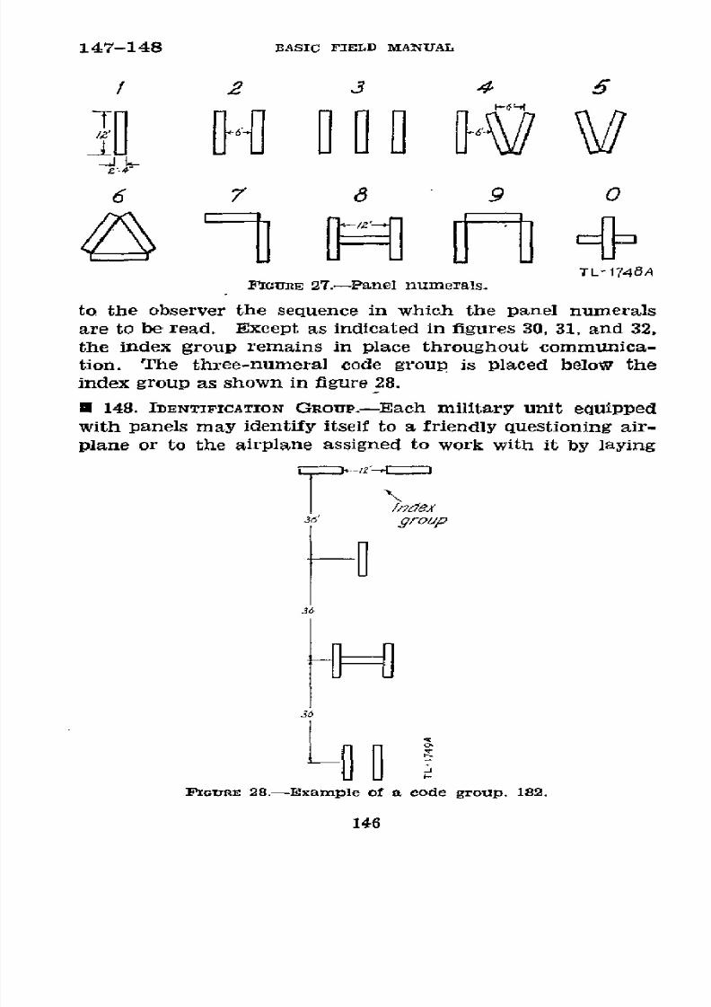
8/16/2019 (1942) FM 24-5 Signal Communication
http://slidepdf.com/reader/full/1942-fm-24-5-signal-communication 150/383
147-148
BASIC
FIELD MANUAL
2
3 4
5
e-'
6
7
8
9 0
TL-
1748A
FIGURE
27.-Panel
numerals.
to the
observer the
sequence in which the panel numerals
are to
be read. Except as indicated in figures 30, 31,
and 32,
the index group remains
in
place
throughout
communica-
tion.
The three-numeral code group
is
placed below
the
index
group as shown in
figure 28.
E
148.
IDENTIFICATION
GROUP.-Each
military
unit
equipped
with
panels
may
identify itself
to a friendly
questioning air-
plane or to the airplane assigned to
work
with it by
laying
3
P
10group
jó
L
FIGURE
28.-Example of a code group,
182.
146

8/16/2019 (1942) FM 24-5 Signal Communication
http://slidepdf.com/reader/full/1942-fm-24-5-signal-communication 151/383
SIGNAL
COMMUNICATION
148-149
out panel numerals forming
a number called an identifica-
tion group, arbitrarily assigned the unit
in
signal operation
instructions.
The
identification group may
consist of
oxre,
two,
or
three
numerals.
These
identification
groups
have
no relation
in
any way
to
the actual numerical
designation
of the
unit.
For
an
example,
see paragraph
265h.
*
149. DISPLAYING
THE IDENTIFICATION GROUP.-a.
The identi-
fication
group
is
displayed
when the airplane
gives a
pre-
arranged
signal
meaning
"display
identification
group." In
order
to indicate
that an
identification
group
is
being
dis-
played
and
not
a
code
group,
a
special
signal or
indicator
for an identification
group
is laid
out simultaneously
with
the numerals.
This consists
of a single
panel
placed about
12 feet above the index group
and
at
right angles to it.
b.
If
the 4th
Field
Artillery Battalion were
assigned
102
as
its identification
group,
this
unit would
identify
itself
by
displaying panels
as
shown in figure
29.
/dent if/c&t/on
group
/7d/COt/Or
36
+0-@D
36
PIGURE
29.-Example
of an
identification
group,
102.
147

8/16/2019 (1942) FM 24-5 Signal Communication
http://slidepdf.com/reader/full/1942-fm-24-5-signal-communication 152/383
149-150 BASIC FIELD MANUAL
c. When
the identification group
consists
of less than
three
numerals,
it is preceded by one or
two
zeros, as
may
be
necessary, in
order
to make a three-numeral
group. For
example,
the
identification
group
8
would
be
displayed as
the number
008.
* 150. TECHNIQUE
OF PANEL
DISPLAY.--a.
General.-No
hard
and fast rules governing
the space
that must be left
between
the panels
composing
any
signal
can
be
laid down. The
distance
between
all panels
should be dictated
by local
condi-
tions as
to
visibility, space
available, height of the airplane,
and the
terrain.
Under
average
conditions,
the
display
of
the
numeral
panels and
the
special
signals should conform
to
the form
and
relative distances
indicated
in
the
exam-
ples shown
in
this manual
and
ir,
the Air-Ground
Liaison
Code.
b. Preparation.-When two
or more
operators are
avail-
able for
laying out the
panels,
the work should
be divided
up
by
specific assignment
of duties. Special
circumstances
and
good
judgment
will
dictate the
best
possible division
of
labor.
Constant
practice
will result
in
developing a
highly
efficient panel
detail
capable
of
operating
with maximum
.speed and
minimum interference or
confusion.
Panel oper-
ators when preparing
to display-
panels will,
according
to
the
number
of
operators
available,
post themselves
in
such
posi-
tions
as will
facilitate
laying out,
changing,
and taking
up
panels
with
the
greatest
possible
speed
and
precision.
When
the
display
of
any
signal has been completed, operators move
away
from the panels rapidly
and
take up such positions
that
they
will not
obscure the signal from
observation
or
cast shadows
upon any
part
of it. The
signal remains dis-
played
until
the
airplane's acknowledgment has been
re-
ceived, whereupon
all
panels
not
in
the initial display will
always
be removed
before
a
new display
is made.
c.
Beginning.-In
order to
commence
working
with
the
airplane, an initial
display
consisting
of the
unit's identifica-
tion group
is
displayed.
This means
"I
am ready
to work."
(See
par.
149.)
In
the event
that
the identification
group
is
not
displayed,
the initial
display will be
the
number "000"
under the
index
group.
This
also means
"I
am
ready to
work."
148

8/16/2019 (1942) FM 24-5 Signal Communication
http://slidepdf.com/reader/full/1942-fm-24-5-signal-communication 153/383
SIGNAL COMMiUNICATION 150-152
d. Continuation.-In order to avoid misunderstandings,
ambiguities, and delays,
the
noncommissioned
officer or
the
senior
operator
in charge of the
panel detailed
calls
out
loudly,
in
separate
numerals,
the signal
to
be displayed,
for
example,
"ZERO ZERO
THREE"
or
"THREE
FOUR FIVE."
Much time will be saved
if
the next signal is
announced
while
the preceding signal
is
being displayed and the airplane's
acknowledgment is being awaited. By so doing,
such opera-
tor
can fix in mind beforehand
his exact movements in
the
next
display.
When this procedure is
followed,
the
announce-
ment regarding
the
signal
to
be
displayed
is
preceded
by
the
phrase, "The next signal will be-."
The
operators
then
await
the command
GO before proceeding to execute the
order.
* 151. REPoRTING.-a.
An airplane
requests the ground sta-
tion
to
identify
itself
by
radio,
pyrotechnics, or lamp signals
and other ways all indicated
in
current
signal
operation
instructions.
b.
The ground station
answers
by
displaying
its
identifica-
tion group.
If
not
previously arranged for, the
ground sta-
tion
will
also indicate
by
panels the joint communication
method desired.
The communication method may
be
changed during a
mission
by displaying the proper panels
or by
sending the
necessary signals. Some of these
methods
are described in
paragraphs below.
c. The
airplane acknowledges by
signals which have
been
prearranged
or
ordered.
* 152. BETWEEN AIRPLANE RADIO
AND GROUND
STATION
HAVING
RADIO
RECEIVER ONLY.---.
The airplane acknowledges receipt
of
each panel
display by sending
R,
if
telegraph,
or ROGER
or WILCO, if
voice.
b. If the airplane
sends the
first message,
the
ground sta-
tion
acknowledges by displaying
the signal
009
meaning
"Re-
ceived",
followed
immediately
by
the next panel
signal.
c.
When the last panel
signal of a message has been
dis-
played and
its
receipt
has been acknowledged by
the
airplane,
the ground station displays the panels meaning "More to fol-
low"
or those meaning "Finish." The latter panels
are
displayed only when the
ground station
desires
the airplane
to proceed on
the
mission.
149
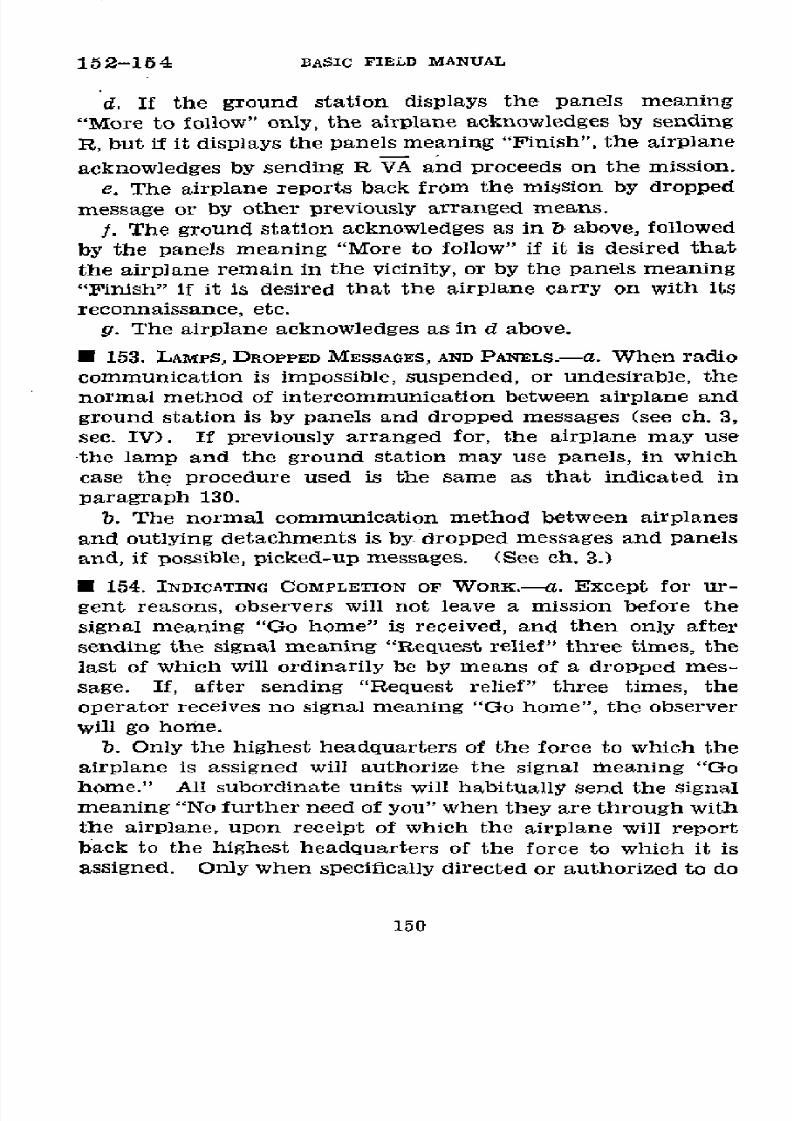
8/16/2019 (1942) FM 24-5 Signal Communication
http://slidepdf.com/reader/full/1942-fm-24-5-signal-communication 154/383
152-154
BASIC FIELD
MANUAL
d.
If
the ground
station
displays the
panels
meaning
"More
to
follow" only,
the
airplane
acknowledges
by
sending
R,
but
if
it
displays
the
panels
meaning
"Finish",
the
airplane
acknowledges
by
sending R VA
and proceeds
on the
mission.
e. The airplane
reports
back from
the mission
by
dropped
message
or
by other previously
arranged
means.
f. The
ground
station acknowledges
as
in b
above,
followed
by the panels
meaning
"More
to follow" if
it is desired
that
the
airplane
remain in
the
vicinity,
or by the
panels
meaning
"Finish"
if
it
is
desired
that
the airplane
carry
on
with
its
reconnaissance,
etc.
g. The airplane
acknowledges
as in
d
above.
* 153. LAMPS,
DROPPED
MESSAGES,
AND PANELS.-a.
When
radio
communication is impossible,
suspended,
or
undesirable, the
normal method
of
intercommunication between airplane and
ground
station is
by panels
and dropped messages (see ch.
3,
sec.
IV).
If
previously
arranged
for, the
airplane
may use
the lamp and
the
ground
station
may use
panels,
in which
case the
procedure
used is
the
same
as that
indicated
in
paragraph 130.
b. The
normal
communication
method
between
airplanes
and outlying detachments is by- dropped
messages and
panels
and,
if
possible,
picked-up
messages.
(See
ch. 3.)
*
154.
INDICATING
COMPLETION
OF
WORK.-a.
Except
for ur-
gent reasons, observers will not
leave
a mission before the
signal meaning
"Go home" is
received,
and
then only
after
sending the signal
meaning
"Request relief"
three
times, the
last
of which
will ordinarily
be
by means
of a
dropped
mes-
sage. If,
after
sending "Request
relief" three
times, the
operator
receives no signal meaning "Go home", the observer
will go
home.
b.
Only
the
highest headquarters
of
the
force
to
which
the
airplane
is assigned
will authorize
the signal
meaning
"Go
home." All subordinate
units
will habitually send the signal
meaning
"No
further
need of you" when they are through with
the
airplane,
upon
receipt
of
which the airplane will report
back
to the
highest
headquarters of the
force
to
which
it
is
assigned.
Only when
specifically
directed
or authorized
to do
150
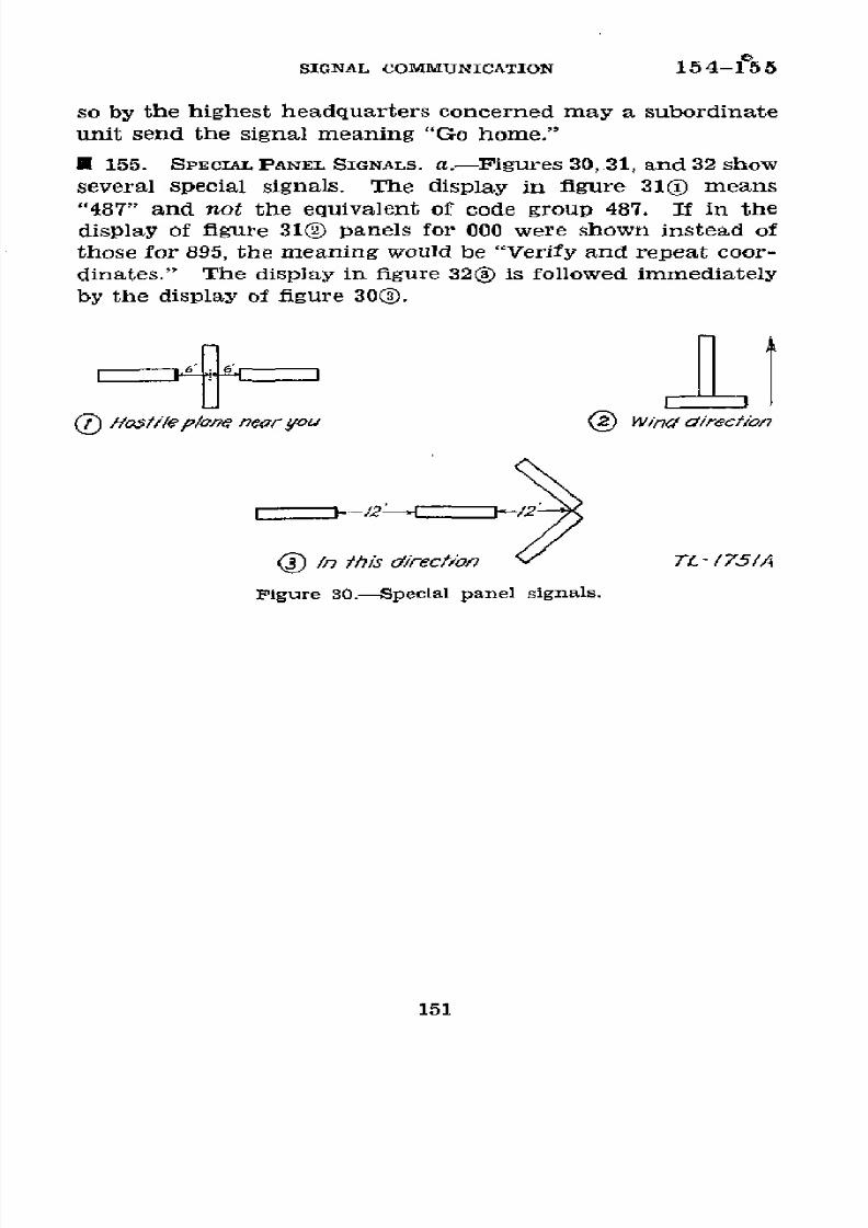
8/16/2019 (1942) FM 24-5 Signal Communication
http://slidepdf.com/reader/full/1942-fm-24-5-signal-communication 155/383
SIGNAL
COMMUNICATION
154-15 5
so
by
the highest
headquarters
concerned
may
a subordinate
unit
send the signal meaning
"Go home,"
*
155.
SPECIAL
PANEL
SIGNALS.
a.-Figures
30,
31, and
32
show
several
special
signals.
The
display
in
figure
31(0)
means
"487"
and
not
the
equivalent
of
code
group 487. If
in the
display
of
figure
310 panels
for
000 were
shown
instead
of
those for
895,
the meaning
would be
"Verify and repeat
coor-
dinates."
The
display in
figure 320 is
followed immediately
by
the
display of figure
300.
Host//lepl/one
nearyou
©
Wind
direcfion
i
n this
direction
vL
-
/75/A
Figure
30.Special
panel
signals.
151
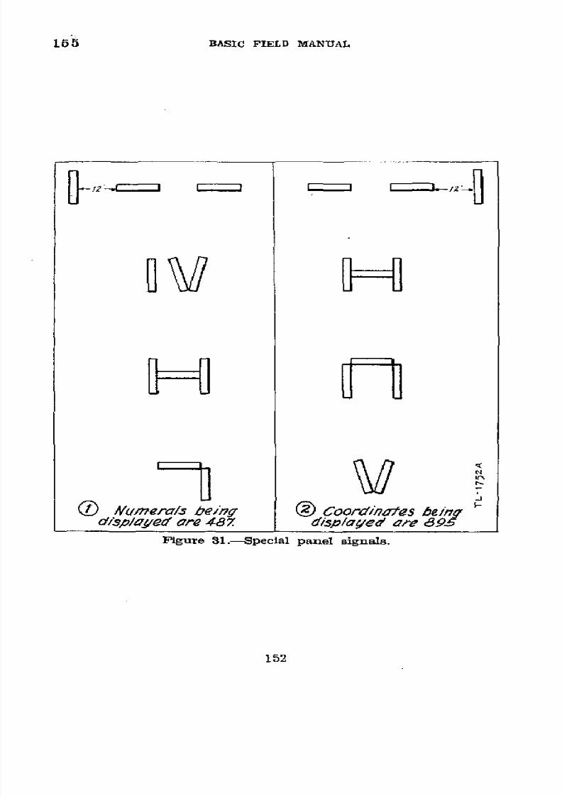
8/16/2019 (1942) FM 24-5 Signal Communication
http://slidepdf.com/reader/full/1942-fm-24-5-signal-communication 156/383
165
BASIC FIELD
MANUAL
n
NO
/umera/s
being
(
Coordinatfes
being
d/sp/ayed
are 48Z
disp/ayed
are
695
Figure
31.-Special
panel signals.
152
8/16/2019 (1942) FM 24-5 Signal Communication
http://slidepdf.com/reader/full/1942-fm-24-5-signal-communication 157/383
SIGNAL
COMIMUNICATION
165
..
1
Re
.
z
A
l
dz®
rrorf
pancel&/
i es iReonnoflireon
to
&e
ndica'teyd
b~
rL-1
53A
next
dispo/y
Figure
32.-Special
panel
signals.
153
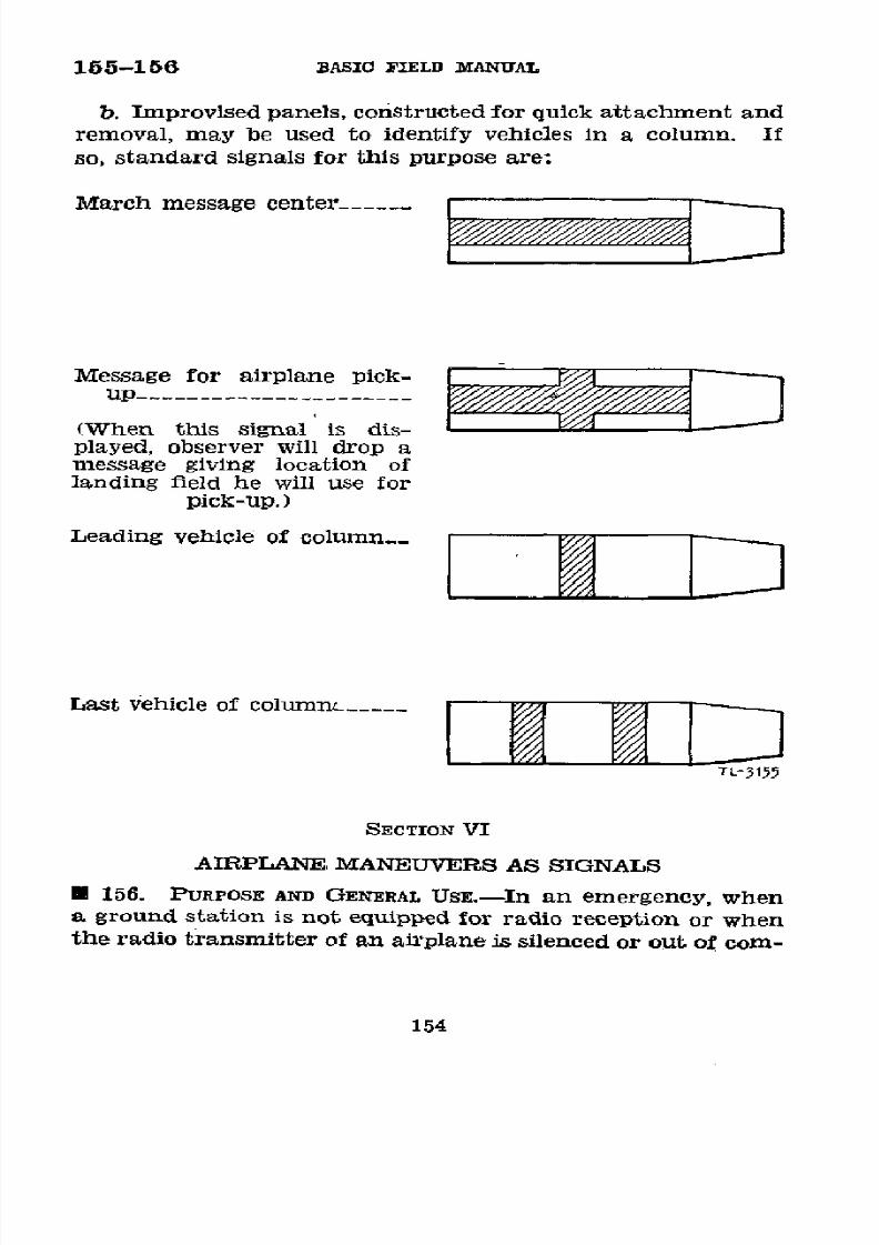
8/16/2019 (1942) FM 24-5 Signal Communication
http://slidepdf.com/reader/full/1942-fm-24-5-signal-communication 158/383
155-156
BASIC
FIELD MANUAL
b. Improvised
panels,
constructed
for quick
attachment
and
removal,
may
be
used
to identify vehicles
in
a column. If
so,
standard
signals
for
this
purpose
are:
March
message
center_------
Message
for
airplane
pick-
up ______________________
(When
this signal is dis-
played,
observer
will drop
a
message
giving
location of
landing
field
he will
use
for
pick-up.)
Leading
vehicle
of column__
Last
vehicle
of
columrn__
--
TL-3155
SECTION
VI
AIRPLANE MANEUVERS
AS SIGNALS
*
156.
PURPOSE
AND
GENERAL UsE.-In
an
emergency,
when
a ground
station is
not equipped
for
radio
reception
or when
the radio
transmitter
of
an
airplane
is silenced
or out
of com-
154

8/16/2019 (1942) FM 24-5 Signal Communication
http://slidepdf.com/reader/full/1942-fm-24-5-signal-communication 159/383
SIGNAL
COMMUNICATION
156
mission, an airplane
may communicate to a limited
degree
with a
ground panel
station by
means
of
various
maneuvers
of
the airplane while in flight. Such signals
are
limited to
a
very
small
number.
No
standard
code
has
been
developed
for
this means of communication
but
any codes used should
be practical
of
performance
by
the airplane
used
and
prefer-
ably
be prescribed
in
signal operation
instructions.
Indi-
vidual units
have
devised
such
codes by prearrangement
with
observation aviation
units designated
to operate with
them.
Adjustment
of
the fire
of field
artillery batteries
using
only
panel
signals
and airplane
wing
signals
is
both rapid and
often
practicable.
155

8/16/2019 (1942) FM 24-5 Signal Communication
http://slidepdf.com/reader/full/1942-fm-24-5-signal-communication 160/383
CHAPTER
7
COMMUNICATION
BY
SOUND
*
157. DEFINITION.-The
transmission
of
messages
by audible
sounds
produced
by
mechanical
or
acoustical
devices,
exclud-
ing
speech,
and
their
direct
reception
by
ear
is
defined
as
sound
communication.
U
158.
SOUND
PRODUCING
DEVICES.
-Such
conunon
sound-
producing
devices
as
whistles,
bugles,
horns,
sirens,
and rat-
tles, and
the sounds
produced
by small
arms,
artillery,
and
motors
of airplanes
in
flight
are
frequently
used
for
sig-
naling.
The bugle
is often
used
to
transmit
prearranged
messages,
and
the
other
devices
mentioned have
also
been
used
in
many
operations.
Except
as indicated
in
paragraph
159,
the
use of
any sound
producing
device
for
this
purpose
may be prescribed
by
a commander.
*
159.
PREARRANGED
MESSAGES
REPRESENTED
BY
SOUNDS.--a.
Orders,
information,
and
other
prearranged
messages
repre-
sented by
bugle sounds
are prescribed
in TM
20-250.
b.
Prearranged
messages
represented
by
whistle sounds
are
prescribed
in other
training
publications.
c. The
signals
from
sound-producing
devices
issued for
use
as
gas
or air
attack alarms
are
prescribed
in
War
Depart-
ment
Training
Circulars,
and the devices
will
not be
used
for
any other
purpose.
156
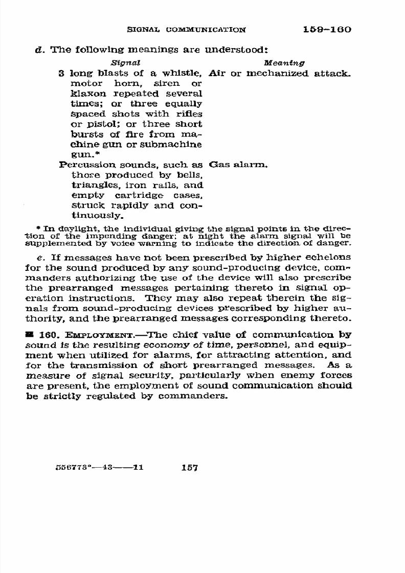
8/16/2019 (1942) FM 24-5 Signal Communication
http://slidepdf.com/reader/full/1942-fm-24-5-signal-communication 161/383
SIGNAL COMMUNICATION 159-160
d. The following meanings are understood:
Signal
Meaning
3
long
blasts
of
a
whistle,
Air or
mechanized
attack.
motor
horn,
siren
or
klaxon repeated several
times; or three equally
spaced
shots with
rifles
or
pistol; or
three
short
bursts of
fire from
ma-
chine
gun
or
submachine
gun.*
Percussion
sounds, such
as Gas alarm.
those produced by
bells,
triangles,
iron
rails,
and
empty cartridge cases,
struck
rapidly
and con-
tinuously.
* [n daylight,
the
individual
giving
the
signal
points in the
direc-
tion
of
the
impending
danger;
at
night
the
alarm
signal
will
be
supplemented
by voice warning
to
indicate
the direction
of
danger.
e. If messages
have
not been
prescribed
by higher
echelons
for
the sound produced
by any
sound-producing
device,
com-
manders
authorizing the use of the
device
will
also prescribe
the prearranged
messages pertaining
thereto
in
signal
op-
eration
instructions.
They
may also repeat
therein the
sig-
nals from
sound-producing
devices
prescribed
by
higher
au-
thority,
and
the prearranged messages
corresponding
thereto.
U 160. EMPLOYMENT.-The chief
value
of
communication
by
sound
is the resulting economy of time, personnel, and equip-
ment
when utilized
for
alarms, for
attracting
attention,
and
for
the
transmission of short prearranged messages. As a
measure
of
signal security,
particularly
when enemy forces
are present,
the
employment
of
sound
communication should
be strictly
regulated
by
commanders.
556773°-43
11
157
8/16/2019 (1942) FM 24-5 Signal Communication
http://slidepdf.com/reader/full/1942-fm-24-5-signal-communication 162/383
CHAPTER
8
WIRE COMMUNICATION
Paragrapls
BSrToN
1.
General
-__-------------------------------
161-182
II.
Field wire line construction-_---------------
183-208
III. Field telephones and centrals
.
.........__.--
209-226
IV. Field
telegraph
sets
and stations
----- __--_----
227-233
V.
Maintenance
of
feld
wire
systems
------
___----
234-243
SECTION
I
GENERAL
*
161.
PURPOSE
AND
SCOPE.-The
purpose of
this
chapter
is
to establish
standard
practice
in
the
installation,
main-
tenance, and operation of
the
field wire systems of tactical
units. This
standardization
is necessary to
insure efficient
wire
communication.
The individual
duties assigned
to the
wire
personnel
of units
are
specifically
explained in the
training publications pertaining to
the different
arms. Com-
plete
technical information
pertaining
to
particular
items
of
wire communication
equipment may be
found
in
references
listed
in
appropriate paragraphs.
*
162.
DEiNmrrioNs.-The following terms used in this
chapter
are peculiar to wire communication. These terms
are
de-
fined in the
sense
in which they
are
used herein. For
deflni-
tions
of general
terms see
paragraph 5,
and
for
definitions
of
those
pertaining to other
means of
signal
communication,
see
pertinent
chapters.
a. Common battery.-A
term
used to
describe
a telephone
system
which
has
current
supplied
to it
from
a
central
source.
b. Construction center.-A
central point other than
a
switchboard from which
wire
crews may
be controlled.
c.
Field telephone.-A
portable
telephone
designed
for field
use.
158
8/16/2019 (1942) FM 24-5 Signal Communication
http://slidepdf.com/reader/full/1942-fm-24-5-signal-communication 163/383
SIGNAl COMMrUNICATION 162
d.
Field telephone switchboard.-A
portable
telephone
switchboard
designed for field use.
e.
Gaff.-A
spur
on
the
inside
of
pole
climbers
which
en-
gages
in the
pole.
f. Local battery.-A term used to
describe
a
telephone
system in
which current
is
supplied
for
talking at each
tele-
phone,
usually from a dry battery contained in the
telephone.
g. Magneto.-A
hand-operated
generator of
alternating
current utilized
to
operate
telephone
ringers
and
switchboard
line indicators.
Local
battery telephones
use a
magneto for
signaling, hence
are
sometimes
referred
to
as magneto
tele-
phones.
h.
Marline.-A
small, loosely
twisted twine
of two
strands
used for tying field wire
to
a support.
i. Monocord suwitchboard.-A
field
telephone switchboard
in
which each
line
terminates
in
a single
jack and
plug.
J. Repeating
coil.-A
transformer of
approximately
unity
ratio used to
superimpose additional circuits on
field
wire
lines.
(See
par.
215.)
k.
Seizing wire.-Soft-drawn
copper
wire, used to
improve
field
wire splices mechanically
and electrically.
1.
Sidetone.-The
audible
sound produced
in
a
telephone
receiver
when
the transmitter
of
the
same telephone set
is
actuated by
sound waves
produced by
speaking or blowing into
the
mouthpiece.
m.
Skinning-The
process
of
removing
insulation from
wire.
n.
Staggering.-The
offsetting
of
splices
in the
two
con-
dUctors
of twisted pair
wire so as
to
prevent
bulkiness and
short circuits.
o. Switching central.-The facility
employing
a telephone
switchboard to
interconnect telephones served and to connect
telephones to trunk lines which
terminate
at
another
switch-
ing
central.
p.
Terminals.-Contacts
or
binding posts conveniently ar-
ranged for connecting
equipment
or circuits.
q. Test station.-An
installation
of
one or
more
terminal
strips cut in
on
a long
trunk or
local
circuit for
test purposes.
(See
pars. 174
and 239.)
r. Wire boom.-A
device sometimes used
in laying
field
wire from a
truck.
159
8/16/2019 (1942) FM 24-5 Signal Communication
http://slidepdf.com/reader/full/1942-fm-24-5-signal-communication 164/383
8/16/2019 (1942) FM 24-5 Signal Communication
http://slidepdf.com/reader/full/1942-fm-24-5-signal-communication 165/383
SIGNAL
COMMUNICATION
164-165
ing
coils,
and
when
this is
done,
the
circuits
are
classified
as
follows:
'1)
A
single
metallic
telephone
circuit may
provide
an ad-
ditional
telegraph
or
telephone
circuit
without
mutual
inter-
ference.
This
additional
circuit
ordinarily
uses
a ground
return
and
is known
as a
simplex circuit
(par. 216),
and the
metallic
circuit
is said
to be
"simplexed."
(2)
Two metallic
telephone
circuits
may
provide
an
addi-
tional telephone
or
telegraph circuit
without
mutual inter-
ference.
This
third
circuit
is called
a "phantom
circuit."
(See
par.
217.)
The
two
metallic circuits are
called "side
circuits"
or "physical
circuits"
to
distinguish
them
from
the
phantom
circuit,
and the
three
together
are
known
as a
"plaantom
group."
Such
a connection,
when
good
ground.
connections
are difflcult
to
obtain,
will
provide greater
signal
security
than
a simplex
telegraph
circuit.
If
the
phantom
circuit of
a phantom
group is
used
to
provide
a
telephone
channel,
this phantom
may also
be simplexed
for
a
telegraph
set (fig. 95).
e 165.
MOVEMENT
OF
COMMAND
POSTS.-The
maintenance
of
wire communication
is
usually more
difficult
during the
move-
ments
of command
posts
than
at
any other
time.
The
ini-
tial installation
of
each
wire
system
is
planned
with
the
object
of
maintaining continuous
wire communication
with
subordinate
units
during
and
after the
movement
of command
posts.
No
fixed
rules
can
be
given,
and ingenuity must
be
exercised.
The methods
given
below
show
solutions
for
cer-
tain
situations,
and
should
be
used
only
as general
guides
for
more
specific
problems.
For
explanation
of
symbols
used,
see paragraph
170.
a. Single-axis
method.-In
figure 33,
assume
that
the
com-
mand
post
of a
unit
is
located
at
3
and
that the command
posts
of
its
subordinate
units
are
at
1 and
6,
respectively.
The
axes of signal
communication
of these
units
are 3-5,
1-2,
and
6-7,
respectively.
The
superior
unit runs
one
circuit
from
3
to
1 via
4
and
another
circuit
from 3
to
6
via
4.
Prior
to
the
movement
of the
command
posts of
the subordinate
units to
2
and
7, respectively,
two
circuits
are
run
by the
superior
unit
from
4
to
5,
one
circuit
is continued
from
5 to
2,
and
the
other
circuit from
5 to
7.
When the
command
post of the
subordi-
161

8/16/2019 (1942) FM 24-5 Signal Communication
http://slidepdf.com/reader/full/1942-fm-24-5-signal-communication 166/383
165
BASIC
FIELD
MANUAL
-u-
LI1
h
1-~~~~~~~~~~~~~~~~~~~~~1I
¡y
a:
-o
o
m
03~~~~~~~~~~~~~~~~~~~~~~0
ir
oul-
03
.
>
d~~~~~~~~~~~~~~~~~
<
ir
z
k?>
E
ot
cr~~~~
u
o~~
g
a:z ~
~
w
o
2
2
O z
~~~~~~
,Og
a
~~~~~~~~~~
~~k"~~~~?~
162
8/16/2019 (1942) FM 24-5 Signal Communication
http://slidepdf.com/reader/full/1942-fm-24-5-signal-communication 167/383
SIGNAL
COMMUNICATION
1
65
nate
unit
at. 6
moves to 7, the 3-4-6 circuit is
used
until
the
moment
the command
post
closes at 6
and
opens at
7. At
this instant the 3-4-6
circuit is
disconnected
at
4,
and
the 3-4
section
of
this
circuit
is
connected
to
the
4-5-7
circuit.
The
*4-6
circuit
may
then be
recovered or assigned to
some other
unit. The procedure
during the movement
of the other
com-
mand post from 1 to
2
is
similar.
b.
Multiple-axis
method.-(1)
In
figure 33, assume the same
initial
locations of command
posts
and
axes
of
signal
com-
munication as before. The superior unit runs
two
circuits,
one
from
3
to
1
and
the
other
from 3 to 6.
It
then
lays
one circuit along
the axis of signal communication of each
subordinate
unit, passing through 2 and
7,
respectively. When
the
command
post of the unit
at
6. moves
to
7, the 6-7
circuit
is
connected
to the
3-6
circuit.
The
superior unit maintains
the
3-6-7
circuit. The
procedure
during
the
move of
the
com-
mand
post
of
the
other subordinate
unit
from
1
to
2
is similar.
(2) To
expedite installation,
the
superior unit
may attach
wire
construction teams
to
subordinate
units
with
instructions
to
lay
wire toward
the superior
unit command
post as
soon
as the
subordinate
unit
establishes a
command
post.
c.
Joint-axis
method.-In
figure
33,
assume
that
the initial
command post of the Unit is located at 3,
and that
the
initial
command
posts of its subordinate units are 1 and
6, respec-
tively.
The axes of signal
communication
of these
units
are
3-1-2-9,
1-2-9, and
6-7-8,
respectively,
the
axis of the superior
unit
coinciding with
the axis
of its
left
subordinate.
The
superior unit
makes the
initial
trunk
installation by
laying
circuits
3-1 and 3-6. Should
all
three
units move
to position
from
a common assembly area
or from the
same column
in
march,
these
circuits
may, by agreement,
be
laid by
the
subordinate
units
en
route to
position.
Should
the
left
sub-
ordinate
unit desire at any
time
to advance
to
another
com-
mand
post,
as
2,
it
lays
circuit
1-2,
and
having
decided
to
open
at 2,
circuit
1-2 is
connected to 3-1
at 1, and signal communi-
cation
is maintained
over circuit 3-1-2. The movement
from
point 1, and the
connecting of circuits at
that
point, are
accomplished without interruption of wire traffic. Assume
that
the subordinate units
have
advanced, by
the
foregoing
method,
to
points
9 and 8,
respectively.
At this time
the
163
8/16/2019 (1942) FM 24-5 Signal Communication
http://slidepdf.com/reader/full/1942-fm-24-5-signal-communication 168/383
8/16/2019 (1942) FM 24-5 Signal Communication
http://slidepdf.com/reader/full/1942-fm-24-5-signal-communication 169/383
SIGNAL
COMMUNICATION
165-168
above
are suited
to
obtaining the initial
installation.
As
soodn
as this installation
has been
completed
an alternate instal-
lation along
different routes
should
be initiated.
* 166.
ORDERs
AND
INSTRUCTIONS.-In divisions
and
higherf
units,
instructions
concerning
the wire system for a particular
operation
are
usually
included
in a
signal annex. In units
below
the division, the corresponding
instructions
are usually
issued orally. However,
the plan of
installation
can best
be
shown by a circuit
diagram and
a
line route
map.
See
in-
structions,
forms,
and examples
in
chapter 10.
,
167.
CIRcuIT DIAGRAM.---a. A circuit diagram
gives sche-
matically the technical
arrangement and
connections of
the
circuits
and terminal installations
of the
wire
system. (See
example, par.
262.)
b.
The circuit diagram
indicates-
(1)
Switching centrals at
command posts
and
establish-
ments served
by
the wire
system,
commercial switching cen-
trals,
test
stations, and
long
local
telephone circuits,
that
is,
circuits to
local
telephones
not
in the immediate vicinity
of
a
switching
central. These
are shown by
their
special sym-
bols (par. 170)
and by their
telephone
directory
names,
or
telephone directory
numbers,
if these
are
used.
Their
loca-
tions
are
indicated by names of map or terrain features
and
by
coordinates. (The
commander
of
the
theater
of opera-
tions
may
prohibit such use of
map
locations
and
coordinates.)
(2)
Number
of circuits, including trunks and
long locals,
between
each of the command
posts or establishments
shown.
(3)
Number
assigned
to
each circuit
(see par. 168).
(4) Manner of connecting each
circuit
into or
through
switching
centrals and
test
stations. This
includes
the
con-
nections for simplex and phantom
circuits.
(5)
Type
of line
construction
used
for
each
line,
such
as
fleld
wire,
open
wire,
cable, commercial
circuits, etc.
U
168. DESIGNATING
LrNES AND
CIRCUITS.---a.
Wire lines and
circuits are given individual
designations
as
published in
orders
from higher authority.
b.
In large
wire
systems,
the designation
of wire
circuits
is
the number of
the
circuit followed by
the
name or
number
165
8/16/2019 (1942) FM 24-5 Signal Communication
http://slidepdf.com/reader/full/1942-fm-24-5-signal-communication 170/383
168
BASIC
FIELD
MANUAL
of
the
line; for example, circuit No.
50,
cable
No.
6, or
circuit
No. 561, New
York-Washington
line.
c.
In
division
wire systems,
a
circuit is
not normally
desig-
nated
by
name
but
by
its
individual number.
d. In
assigning numbers
to
wire
circuits
the
following
general
rules are
observed:
(1) No two
circuits in
a
named
or numbered wire
line
are
given the
same
number.
(2) No two
circuits constructed
by the
same organization
during
a single
operation
are given
the same
number.
(3)
All
wire
lines
are
divided
into
sections.
A
section
begins and
terminates
at
successive
switching centrals, test
stations, or (in the case of a long local) at a telephone.
A
circuit
passing from one
section to
another
is given
a different
designation
on entering the new section.
e.
In
the
wire systems
of
divisions and lower units,
con-
struction
and
maintenance
are
facilitated
by a
numbering
system which identifies the
general
position of each circ lit
with
respect
to
other
circuits
in
the
same system.
The
ex-
ample
in
paragraph
262
illustrates
one
system
of
numbering
which
is
given only
as
a guide.
This
system provides for
the allotment of a block of numbers to each section of
the
line
along
the
axis
and
to each
section of the
line laterally
from
the axis both to
the
right and
left.
Beginning
at the
rear
echelon
of the
division,
each section of the line along
the axis
is allotted
a block
of 10 numbers
of three digits
each-hundreds,
tens,
and
units. The hundreds
begin
at
1
and
increase
in
arithmetical progression
for
each section
of
the line.
The last two digits
are
from
01 to
10
in each sec-
tion
of the line.
Laterally to the left
each section
of
the
line
is allotted
a block of nine
numbers, the hundreds'
number
being the same as the
section
of the axial line,
terminating at
this point of divergence. The
last two
digits
are from 11 to
19.
The
next
section
to
the
left
maintains the
same
hun-
dreds'
number
and takes
the next
block
of nine
numbers
beginning with an odd number, that is, 31
to
39, etc. The
same
method
is
applied to
the allotment of numbers to the
sections
to
the right of the
axis,
using,
however,
for
the
last
two digits, blocks of
nine beginning
with
even numbers; that
is, from
21
to
29, 41
to
49, etc.
166

8/16/2019 (1942) FM 24-5 Signal Communication
http://slidepdf.com/reader/full/1942-fm-24-5-signal-communication 171/383
SIGNAL COMMUNICATION 169-170
*
169.
LINE
ROUTE
MAP.-A line route map
is
a map,
map
substitute, or
overlay
suitably
titled on which
are shown the
actual or projected routes
of
wire
circuits,
but
not
the
actual
connections at
centrals
or
test stations. (See example,
par.
263.)
Its
principal use is
in
reporting the physical
location
of wire
circuits
as
actually
laid
for
the information of wire
personnel.
If
an
overlay,
at
least
two
orientation
points
taken
from the map must
be shown
in addition,
and a
refer-
ence must be
made
on
the
overlay
to
the
map used
unless
otherwise
directed
by
the commander of the
theater
of opera-
tion. The
line
route map
contains
as
few
lines,
symbols,
and
notations as
is
consistent
with
its purpose, but
shows
the
location of each
headquarters or establishment
served
by
the wire
system,
and locations of switching
centrals, test
stations,
and
long locals,
the type of
line
construction, and
the
number of
physical
circuits
in each
section of the line.
* 170. SPECIAL
SYMBOLS.-The
following
special
symbols
are
authorized for
use
as indicated
in
or
in addition
to
those
authorized in
FM 21-30.
167
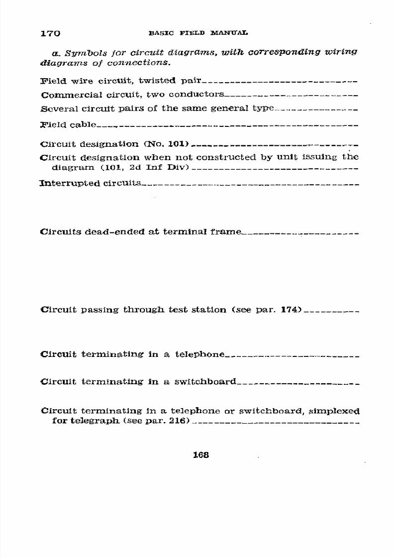
8/16/2019 (1942) FM 24-5 Signal Communication
http://slidepdf.com/reader/full/1942-fm-24-5-signal-communication 172/383
170
BASIC FIELD
MIANUAL
a.
Symbols for
circuit
diagrams,
withl
corresponding
wiring
diagrams
of
connections.
Field
wire circuit, twisted
pair_____-----------------------
Commercial
circuit,
two
conductors_-----------------------
Several
circuit
pairs of
the same
general
type__-------------
Field
cable _----------------------------------------
Circuit
designation
(No.
101) ------------------------------
Circuit
designation
when
not
constructed
by
unit issuing
the
diagram
(101, 2d Inf
Div) ______________----------------
Interrupted
circuits__--____________-----------------------
Circuits
dead-ended
at
terminal
frame .-------------------
Circuit passing
through
test
station (see
par. 174)----------
Circuit
terminating
in a telephone_--__--------------
_____
Circuit
terminating
in
a
switchboard____
------------
Circuit
terminating
in
a
telephone
or switchboard,
simplexed
for
telegraph
(see
par.
216)
______________________________
168

8/16/2019 (1942) FM 24-5 Signal Communication
http://slidepdf.com/reader/full/1942-fm-24-5-signal-communication 173/383
SIGNAL
COMMUNICATION
170
,SYMsOls
W/R/NG
D/AGRAMS
_-pr-
-5prtcab/e-
CL
-101-
6'
-1.-CORAL-
TERMIINAL
STR/P
TERMINAL
TR/P
o
T]
0
7.-/J5001)(
169

8/16/2019 (1942) FM 24-5 Signal Communication
http://slidepdf.com/reader/full/1942-fm-24-5-signal-communication 174/383
170
BASIC
FIELD
MANUAL
If required
for clarity,
show
simplexed
telegraph
set
or
tele-
typewriter connection
(see
par. 216)____----------
_______
Simplexed circuit bridged around a switchboard; telephone
circuits
terminating
in
the
switchboard (see par.
229) _____
Telegraph
way station on simplexed circuit,
telephone cir-
cuits
terminating
on
the
switchboard
(see
par.
230)
_____
Telegraph way
station on simplexed circuit, telephone circuit
bridged
around
the
switchboard (see par.
230 __________
Phantom
group
terminating
in a
switchboard
(see par.
217)__
Side
circuits of two
phantom
groups
terminating
in a
switch-
board,
the
phantom
circuit
bridged
around
the
switchboard_
Phantom group
terminating
in
a
switchboard,
phantom
cir-
cuit
simplexed
for
telegraph
(see
par.
217b)--------_----
Two
phantom groups terminating
in
a
switchboard, the
phan-
tom
circuit simplexed and
bridged
around
the switchboard_
170

8/16/2019 (1942) FM 24-5 Signal Communication
http://slidepdf.com/reader/full/1942-fm-24-5-signal-communication 175/383
SIGNAL
COMMUNICATION
170
SYMBO Ls WIRINe
D/AGRAMS
"T
TL*1c1E/
171

8/16/2019 (1942) FM 24-5 Signal Communication
http://slidepdf.com/reader/full/1942-fm-24-5-signal-communication 176/383
170
BASIC
FIELD
MANUAL
b.
Symbols
for line route maps,
indi-
cating wire
lines.
Field wire
line ------------------------
Number
of
circuits
in a field wire line ___ 4
Pield cable--------------------------- -5pr
Standard
pole
line-------
-------------
c.
Basic
symbols
for circuit
diagrams,
Zine route
maps,
traffLc
diagrams, and
sig-
nal
operation
maps.
Switching
central located at
an echelon
of
a headquarters -------------------
Switching central
-______
-__
Commercial
switching
central (add com-
mercial
designation
of the
central on
7Iomt
top
of symbol)
______________--------
Test station
or terminal frame-_________ .name)
Probable future location of a cavalry
command post, indicating a
point
on
the axis
of
signal
communication_-_____
Probable
future
location
of an
infantry
command
post, indicating a point on N
the
axis
of
signal
communication.____
Probable
future
location
of a field
artil-
lery
command post,
indicating
a
point
on the axis
of
signal communication__
d.
Symbols for
traffic diagrams.
Communication channel_______________
Number
of
communication
channels___
3
Switching
central-_____________________
Telephone____________________________
172

8/16/2019 (1942) FM 24-5 Signal Communication
http://slidepdf.com/reader/full/1942-fm-24-5-signal-communication 177/383
SIGNAL
COMMUNICATION
170-171
Teletypewriter
central
.________----------
t
Teletypewriter
---
__/__------------------_
.C/sin)
.
Telegraph
set
-T__
_______._--.----
//s
e. Application
of
symbols.
Switching
central
at
command
post,
jfi
First
Army
___----------------------
Switching
central
at
command
post,
II
Army
Corps_---_--------------------
GETTYSBURB
Commercial
switching
central______-----
ioml
Commercial
switching
central
controlledGnYvseuRG
xxxX
or
operated
by army
signal
troops.___.-
m
tL- 135s/
*
171.
TELEPHONE
CAPABILITIES.---a.
The
greatest
advantage
of
the
telephone
is that
it
affords
immediate
personal
con-
tact
between
individuals.
Disadvantages
of
the
telephone
are
lack
of
record
of
the conversation
and
the tendency
to
talk
too
long.
b.
The
efficiency
of the
telephone
system
depends
upon
a
number
of
factors,
the
most
important
of which
are-
(1)
Type
of wire
line
constructien.
(2)
Type
of
equipment
used.
(3)
Weather.
(4)
Training
of
the
personnel
operating
and
using
the
system.
c.
The
distance
over which
satisfactory
telephone
com-
munication
is
possible
is
determined
by the
electrical
charac-
teristics
of
the
telephone
circuit.
A given
type
of wire
circuit
under
normal
conditions
has
a definite
talking
range.
d. The
following
conditions
tend
to decrease
the
efficiency
556773°-43-
12
173

8/16/2019 (1942) FM 24-5 Signal Communication
http://slidepdf.com/reader/full/1942-fm-24-5-signal-communication 178/383
171-174 BASIC
FIELD
MANUAL
of
telephone
circuits
and the range
of
telephone communica-
tion:
t1)
Snow,
ice,
rain,
heavy
dew,
or
fog.
(2) Poor
electrical
insulation
between wires and
ground.
(3) Moisture
in the telephone
instrument,
especially
in
the transmitter.
(4) Weak
dry batteries in local
battery
(magneto)
tele-
phones.
(5)
Additional telephones
bridged
across
a
circuit.
(6) Additional
switchboards involved in a connection.
* 172.
SWITCHING
CENTRALS AT COMMAND POSTS.-A
switching
central
is
established
at
each echelon of a headquarters
where two
or
more local
telephones are installed
to
provide
flexible
intercommunication
between local telephones,
con-
nections
to trunk circuits to
other
units, and a place at which
all
circuits
are
available
for
test
and
from
which
maintenance
may be
directed.
*
173.
SWITCHING
CENTRALS
OTHER
TEIAN
AT
COMMAND
POSTS.-A
switching central is
installed
at a point other than
an
echelon
of
a headquarters
for the principal
purpose of
trunk
switching.
Their
judicious
use enables
better
telephone
service
to be
furnished
with
the same
number
of trunks,
but
they
require
additional
personnel and equipment,
necessi-
tate
an
additional
switching
operation
with
increased
possi-
bility
of
interruptions
to
service,
and
introduce additional
transmission losses.
*
174. TEST
STATIONS
(pars.
200 and
239)
.- Test
stations
may
be
installed
on a wire
line to
facilitate
the
testing
and rear-
ranging of circuits.
They may
be
located
at points where
cir-
cuits
diverge at
the
end of
a wire
line
which does not
ter-
minate
in
a switchboard, near points
where
circuits
are
most
exposed to damage, at
probable
future.
locations
of com-
mand
posts,
or
at
other
convenient
points
on
the
line.
If a
command
post is
established
where a
test
station has been
previously
installed, the
test station can easily
be converted
into
a
switching central.
Test stations are
usually
given a
geographic
designation,
for
example,
Jones Farm Test.
In
the
situations
given in paragraph
165a
and d, the
location
of
test
stations
at points 4 and
5 would
facilitate
the rearrange-
174
8/16/2019 (1942) FM 24-5 Signal Communication
http://slidepdf.com/reader/full/1942-fm-24-5-signal-communication 179/383
SIGNAL
COMMUNICATION
174-175
ment of circuits
after the movement of the
command posts
of
the
subordinate units. (See
par. 239
for
operation of
test
station.)
A
special
type
of
test station
known
as
a construc-
tion center may be established
to
provide a
point
on the edge
of
the command post
area where
the construction chief
may
test
long local
and trunk
circuits,
to eliminate unnecessary
traffic of wire
construction
vehicles
in
the
command
post
area, and to
make possible the
use of a single
cable
through
the
area from
the
construction center to the
switching
central.
* 175.
TELEPHONE
DIRECTORY.--a.
To
simplify
and
expedite
the
operation
of field telephone
systems,
particularly-within
divisions, a
telephone directory
may
be used when prescribed
by
the commander. This directory consists of two
parts
which
are issued together as
one item
of signal
operation in-
structions. (See example, par. 265m.)
When
a telephone
directory is used,
names
are assigned to
switching
centrals.
Within
a
division, all
names
begin
with
the
same
initial
letter
and
when once
assigned remain
fixed and are not changed
except
when
necessary to
avoid conflict
with directory names
of other
units.
b.
Each organization,
office,
and
installation
reached
by
telephone
but not served by its own switching central, is
given a
fixed
number.
To
prevent confusion, the
superior
tactical
commander
should prescribe the same fixed number
for
use
throughout
his
command.
Directory numbers,
when
assigned, remain fixed. Within the limitations of
equipment,
it
is
desirable that the switchboard jack number correspond
to the
directory number
assigned to
the organization,
office,
or
installation.
c.
Directory
names
and
numbers
are
not
intended
for
secrecy, but may be prescribed
for
purposes of simplicity,
accuracy, and speed in the handling of telephone calls. To
fulfill
its
purpose,
the
telephone
directory must
be
habitually
used by all telephone switchboard
operators
and telephone
users. However,
operators
should be instructed to
put
through calls
regardless
of how
they may
be placed. A copy
of the telephone directory should be attached
to
each field
switchboard and telephone in use.
175
8/16/2019 (1942) FM 24-5 Signal Communication
http://slidepdf.com/reader/full/1942-fm-24-5-signal-communication 180/383
J.75-176
BASIC
FIELD
MANUAL
d.
In
larger
units, such
as
corps
and
field
armies,
the
use
of
the
telephone
directory
often
becomes
impracticable
because
of
the
increased
difficulty
for
all
concerned,
par-
ticularly
the
switchboard
operators,
in memorizing
the direc-
tory
names
of the
many
switching
centrals
in
the
larger
system.
In such
systems, the
briefest
generally
understand-
able spoken
abbreviation
of the
designation
of
the organiza-
tion
whose
headquarters
is served
by
a switching
central may
serve
as
the
telephone
directory
designation
of
the
switching
central;
for
example,
"First
Army",
"Ninth
Corps"
or "First
Battalion, Seventh"
for
"First Battalion,
Seventh
Infantry"
when
no other
organization
designated
by
seven
is
served
by
the
same
system.
F 176.
TELEPHONE
CONVERSATrON.--a.
In
placing
a telephone
call
the
complete
designation
of the
party
desired
is given
to
the
switchboard
operator,
including
the
directory
name
of
the
unit
and the
directory
number
of
the party.
However,
when
placing
a
call
to
a
party
at
the
same
headquarters
or
echelon
served
by the same
switchboard,
it
is
not
necessary
to
give
the
directory
name of
the
unlt.
b.
In
answering
a
telephone
call,
the
expression
"Hello"
should
not
be
used.
The
individual
answering
the call
states
the
directory
name
and number
of
that
telephone
and
identi-
fies
himself,
as
"Magic
three,
S-3 (or
Captain
Jones)
speaking."
c.
Telephone conversations
should
be
made
brief
by
mentally
preparing
the subject
matter
beforehand
so
as
not
to
deprive
others
of
the
use of
the circuits.
The
telephone
should
not
De
used
for
long
reports, orders,
or
messages
when
messenger
or telegraph
communication
would
serve
as
well or
better.
Conversations
must
be discrete
because
secrecy
is
never
assured;
they may
be
intercepted
by
direct
tapping
of
the line,
by
induction
from
the
lines,
and by
leaks
to the
ground
and
thence
to
enemy
listening
sets.
d.
No
unnecessary
conversations
should be
held
with
the
switchboard
operator,
and he
should
be spoken
to
in
a
civil
manner.
In
case
it is desired
to make
a complaint
regarding
the
service,
it should
be made to
the
chief
operator
or to
the
signal
or
communication
officer.
The
operator
should
not
be directed
how
to route
a call,
nor should the
calling
party
176

8/16/2019 (1942) FM 24-5 Signal Communication
http://slidepdf.com/reader/full/1942-fm-24-5-signal-communication 181/383
SIGNAL
COMMUNICATION
176-178
attempt
to
route
his own
call
by
merely
asking
for
connec-
tion to
a
certain
central.
The
operator
is best
prepared
to
put through
a
call
with
minimum
delay
when he is given
the
complete
designation
of the party
to be called.
*
177.
CONFERENCE
CALLS.--.
At
certain
times
it is
desirable
for
a
commander
or
one
of his
staff
officers to
obtain
telephone
connection
with
two
or
more
other individuals
at
the
same
time
in
order
to
transmit
instructions or
information to
al]
parties
simultaneously.
For this
purpose
the
conference
cal]
is used.
b. A
conference
call
is
obtained
by
the
calling
party
stating
to
the operator
"Conference
call," giving
the telephone
direc-
tory designations
of
the
parties
desired,
such as "Dragoon
six,
Domino
six,
Diamond
six,"
and
giving
his
own
directory
designation
if necessary.
The
calling
party
may
instruct
the
operator
that in the
absence
of
the
particular
party
called
certain
other
staff
officers
or
their
assistants
will
be satisfac-
tory. After
placing
a conference
call,
the
calling
party
may
hang up
to
wait
recall by
the
operator.
The
connection
i,
established
by the
operator
as described
in paragraph
3,
appendix
I.
* 178. PHoNETIC
ALPHABET.-a.
Certain
letters
of the
alphabet
have similar
sounds
and
are
often
confused
in telephone
conversations.
To
avoid this
difficulty,
the
following
pronun-
ciation
of
letters
is prescribed
for
all
voice
communication,
including
telephone
and
radio:
Letter
Spoken
as-
Letter
Spoken
as-
Letter
Spoken
as-
A
Afirm
J
Jig
S
Sail
B
Baker
K
King
T
Tare
C
Cast
L
Love
U
Unit
D
Dog
M
Mike
V
Victor
E
Easy
N Negat
W
William
F Fox
O
Option
X
X-ray
G
George
P
Prep
Y
Yoke
H
Hypo
Q Queen
Z
Zed
I
Inter
'
R Roger
1
Interrogatory
s used
in place
of lnter in
joint Army-Navy
operations.
177
8/16/2019 (1942) FM 24-5 Signal Communication
http://slidepdf.com/reader/full/1942-fm-24-5-signal-communication 182/383
178-179
BASIC
FIELD
MANUAL
b. The
words of
the
phonetic
alphabet are used
in
place
of
the
letters
they
represent
just as in
spelling a word.
Ex-
pressions such
as
"A
as
in
Afirm"
or
"A
for
Afirm"
are
not
used. Por example,
in
transmitting the words "Barts church"
the word Barts is
likely
to be
misunderstood.
The transmis-
sion
is as
follows: "Barts,
spelled
Baker-Afirm-Roger-Tare-
Sail, church."
c.
The
phonetic alphabet
is
also
used
in
the transmission
by
telephone
of
coded messages.
Por example,
the
code
group
XISV is
transmitted
as "X-ray-Inter-Sail-Victor."
*
179. PRONUNCIATION
OF
NUMERALS.---a.
The
following
pro-
nunciation of numerals is
prescribed
in telephone transmis-
sion:
Numeral Spoken as- Numeral Spoken
as-
0 Ze-ro
5
Fi-yiv
1
Wln
6
Siks
2
Too
7 Sev-ven
3
Thuh-ree
8 Ate
4 Fo-wer 9 Ni-yen
b.
Numbers are transmitted
as numerals or
digits
except
in the
case
of an
even hundred
or
thousand, when the word
hundred
or
thousand
is
used.
Examples:
Number
Spoken
as-
44
Fo-wer
fo-wer.
80 Ate
ze-ro.
136 Wun
thuh-ree
siks.
500
Fi-yiv
hun-dred.
1478
Wun
fo-wer
sev-ven
ate.
7000
Sev-ven thow-zand.
16000
Wun
siks thow-zand.
c. When giving a telephone
number
to
a
switchboard
oPera-
tor,
speak
the directory name
deliberately and distinctly,
pausing between
the name
and
first numeral. Speak each
178
8/16/2019 (1942) FM 24-5 Signal Communication
http://slidepdf.com/reader/full/1942-fm-24-5-signal-communication 183/383
SIGNAL
COMMUNICATION 179-181
numeral
separately, pausing slightly between numerals.
Examples:
Directory name
and
rnumber
Spoken
as-
Table 44 -..------------.......
Ta-ble,
fo-wer fo-wer.
Trkey 80. -------------------............
Tur-key, ate, ze-ro.
Track 6100
----- ---- Track, siks,
wun, hun-dred.
* 180.
TELEGRAPH AND TELETYPEWRITER CAPABILITIES---a.
The
telegraph
is
one
of
the
most
rapid and accurate
electrical
means
of
transmitting messages and its value in a field
wire
system must never be overlooked. A failure
to utilize tele-
graph channels will
seriously
overburden
any
field telephone
system that may
be installed
during the normal
time
allowa-
ble and will defeat the principal purpose of the telephone.
In suitable installations, telegraph
messages
and telephone
conversations may
be
transmitted
simultaneously
over the
same
circuit
without mutual interference
(par.
164c(1))
by means
of
the
simplex
circuit
which
will be installed on
every wire line provided
the
units being served by the
wire
have
the equipment
necessary.
Although the ranges
of
tele-
phone and telegraph instruments are
in general
limited
by
the same factors,
most
telegraph instruments have a much
greater range than do; telephones over a
given
circuit.
b. The teletypewriter is an instrument
designed
for in-
terchanging printed
messages
between
two
or
more
stations.
It is employed
between
higher headquarters in the same man-
ner
as the telegraph is
employed
between headquarters of
units
within
a
division. A
military
teletypewriter is
illustrated
in
figure
34;
for data on
its
employment, see FM 11-5, and
for information
regarding
the installation and maintenance
of such
equipment,
see
TM
11-353.
*
181.
TELETYPEWRITER
CENTRAL
(TTC).--a.
The
usefulness
of
the teletypewriter as a
signal cornmunication agency is tre-
mendously increased by the teletypewriter central. In
the
military
service, this is abbreviated as Ttc. The abbreviation
for
a
commercial teletypewriter exchange,
to
which
military
operated teletypewriters may
be connected
in certain situ-
179
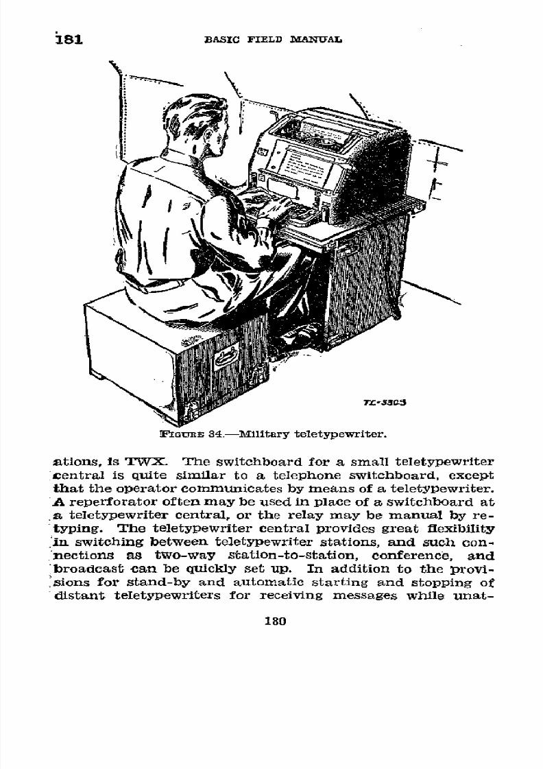
8/16/2019 (1942) FM 24-5 Signal Communication
http://slidepdf.com/reader/full/1942-fm-24-5-signal-communication 184/383
181 BASIC
FIELD MANUAL
nFGURE
34.-Military
teletypewriter.
ations, is TVX.
The
switchboard for
a
small teletypewriter
central
is quite similar to a telephone switchboard, except
that
the
operator
communicates
by means of
a teletypewriter.
A reperforator often may
be
used in place of a switchboard
at
a
teletypewriter
central,
or
the
relay may
be
manual
by
re-
typing.
The
teletypewriter central provides great flexibility
in switching between teletypewriter
stations,
and such
con-
nections as
two-way station-to-station, conference,
and
broadcast can
be
quickly set up.
In addition to
the provi-
sions for
stand-by and
automatic starting
and
stopping
of
distant teletypewriters
for receiving messages while unat-
180
8/16/2019 (1942) FM 24-5 Signal Communication
http://slidepdf.com/reader/full/1942-fm-24-5-signal-communication 185/383
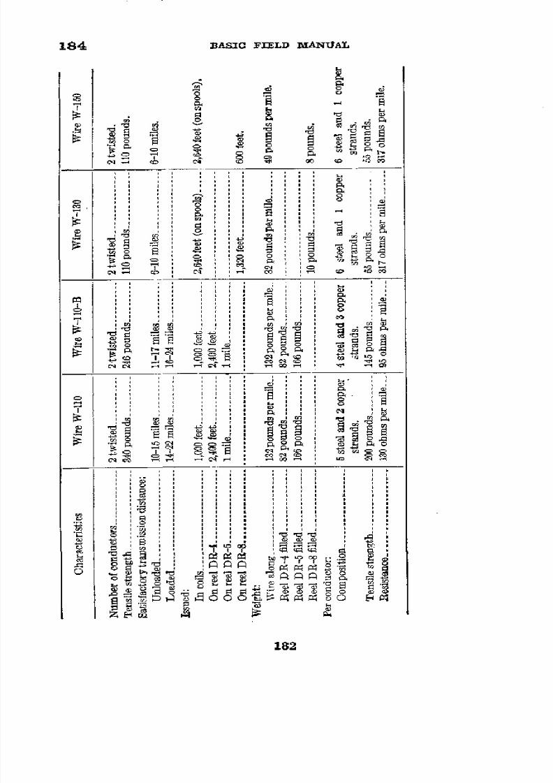
8/16/2019 (1942) FM 24-5 Signal Communication
http://slidepdf.com/reader/full/1942-fm-24-5-signal-communication 186/383
184
BASIC
FIELD MANUAL
.
o
o
cB
ob
1 0r o
N _ C ,
m
,
_
,
l
T
"
- '
E
E
i
18
'e
:
·
~
~
§~
P
e
a
B>
O
O°
o
-a',
: ',=
I -
CoCoi
i i i
: 3 ,I , o
| °tes
Cere
e8oW
> t
EE
B
.aCo
¡4 S E
o
o oaaa'1

8/16/2019 (1942) FM 24-5 Signal Communication
http://slidepdf.com/reader/full/1942-fm-24-5-signal-communication 187/383
SIGNAL COMMUNICATION
185
* 185. nFELD
WIRE
SPLICES.---a.
General.-Splices
in a fleld
wire
line
are present
of
necessity
and
are
vulnerable
points
in
the
circuit; as such
they
merit
sufficient
time,
effort,
and
matériel to be
made
properly.
Every
soldier
engaged
in
com-
munication
work should
be able
to
make
a
proper wire
splice.
The
ideal
splice
would
be
indistinguishable
electrically
or
mechanically
from
the unspliced
wire.
In
practice, this
can-
not
be
attained,
and
consideration
must
therefore
be given
to the following
characteristics
of splices:
Tensile
strength
Electrical
conductivity
Insulation
resistance
Protection
against
weathering
and
abrasion
Flexibility
and bulkiness
These factors must
be
balanced
against
the time
required to
make the splice.
The
standard
field
wire splice
which
best
meets
those requirements
comprises
a
wire
knot tie,
seizing
wire
to
bind
the
tie,
and
tape
for insulation.
(1)
Square
knot.-A
properly
made square
knot
between
the
two
ends of a
conductor produces
a
tie
which
will not
pull oUt.
(2) Seizing
wire.-(a) A
flexible field wire
of high tensile
strength
will
necessarily
have a
number of steel
strands which
are difflcult
to
manage due
to
their
temper.
The
natural
tendency
of the strands
to spring
up prevents
the
splice from
staying
tightly
wrapped and
the
ends
of
the
steel
strands
tend
to puncture
through
the
insulation
and render
the
splice
unserviceable.
In
making
the standard
splice,
seizing
wire
is wrapped
around
the
conductors
after
the
square knot is
tied. This
keeps the strands
in
place
and the binding
effect
of
the
seizing wire
on both
ends
of a spliced
conductor,
to-
gether with
the
large
contact area,
produces a
splice
of
high
and constant
electrical
conductivity.
Under
conditions
of
low
and
variable
conductivity
such as
may exist
in a
splice
made
by a knot
alone, a circuit
becomes
noisy
and
interferes
with
telephonic
communication.
(b)
If
a wire
conductor is
sufficiently
flexible,
it
can
be
wrapped on a
small
radius without
spreading
and seizing
wire
can
be
dispensed
with
in
a properly
made
splice
(such as
described
for
wire
W-130).
183

8/16/2019 (1942) FM 24-5 Signal Communication
http://slidepdf.com/reader/full/1942-fm-24-5-signal-communication 188/383
185
BASIC FIELD
MANUAL
(3)
Insulation.-The primary
reason for insulating
a
splice
is
to
render the
resulting
circuit
as satisfactory electrically
in
wet
weather
as
in
dry
weather.
Electrical
insulation ade-
quate
to meet this
requirement
can
be obtained
only
with
a
minimum
of
two
layers of rubber
tape
and two
layers
of
friction
tape.
(See
par.
187.)
(4)
Bulk.-The
physical
size
of an insulated
splice is no
criteria of its ability to
withstand
service conditions satis-
factorily.
If properly made,
a
field wire
splice
is adequately
flexible
for service
use, and
its
bulk is such
that it will not
seriously
affect
the
wire
capacity
of
a reel,
since
this
is
determined
primarily by
the ability of personnel
to wind
wire
smoothly
and
uniformly. Extremely
bulky splices are
usually
indicative
of
the need for
further
training of the
individual
making
the
splice.
b. Standard field wire splice.-This
splice, utilizing copper
seizing wire
W-71, is
used
on
all
heavier
types
of stranded
conductor
field
wire.
(1)
Teamwork
in splicing.-If two
men
are
available,
the
over-all time for the splice
can
be
greatly
reduced if
they
have
a
standard
cooperative
method and
function
as a team.
Only
the teamwork
splice
is
described; obvious
modifications
of the
procedure can be
made
if one man is
working
alone.
(2)
Staggering
splice (fig.
35).-Each
man prepares one
of
the two wires
which
are
to
be spliced
together.
To obtain
a
uniform stagger
which
will
insure
equal
tension
on
both
conductors
when the
splice
is completed,
each
man
measures
back
one pliers'
length (about 6 inches) from the
end
of one
T -/7/14
FIGURE
35.-Staggering splice.
184

8/16/2019 (1942) FM 24-5 Signal Communication
http://slidepdf.com/reader/full/1942-fm-24-5-signal-communication 189/383
SIGNAL
COMMUNICATION
185
conductor
of
the
wire pair
he is preparing,
and
cuts off
the
conductor thus
measured. Each
man now has
two conduc-
tQrs,
with one
cut so as
to
be
one
pliers'
length
shorter than
the
other.
(3)
Crushing insulaton.-Eachman
now
begins
crushing
the
insulation
on
his
long
conductor
at
the
point
where the
short
one ends,
that
is,
one
pliers'
length
from the
end of
the
long conductor.
(See
fig. 36.)
Using
the
heel
of
his
pliers,
FIGURE 36.-Crushing
insulation on
long
conductors.
he crushes the insulation
toward the
end
for
a
distance of
about
4
inches,
leaving
about
2 inches of the insulation
un-
crushed on the
end
of the conductor.
He next
measures
back
one
pliers'
length
along
the
short
conductor,
and
in a
similar
manner
crushes about
4 inches of its insulation.
(See
fig.
37.) The
uncrushed insulation
remaining on
the
ends
of
the
conductors
holds
the
strands of the
conductors
together,
prevents
possible
injury
by the steel
strands
to
the splicer,
and
greatly reduces
the over-all
splicing
time.
(With some
types of pliers,
it may
be necessary to
improvise shims
from
sheet
metal in order to
crush
the
insulation.)
(4)
Skinning
conductor.-Each
man
scores
or
rings
the
crushed
insulation of both
conductors with the
cutting
edges
of
his pliers at
a point
on the
crushed
section
about
1/2
inch
from
the
point
at which
the
crushing began.
He
then bares
about 31/2
inches
of
the conductor
by changing
the
hand grip
on
his
pliers
(fig. 38) and
drawing
the
cutting edges of
his
pliers straight along
the conductor so
as
to
push
the
crushed
185

8/16/2019 (1942) FM 24-5 Signal Communication
http://slidepdf.com/reader/full/1942-fm-24-5-signal-communication 190/383
185 BASIC FIELD
MANUAL
insulation ahead of the
pliers. In
this operation,
care
is
taken
to draw the
pliers perpendicularly
along the conductor,
as drawing
the
pliers
at
any
appreciably
different
angle
to
-
_~
T/.~~L-1737
FGIoRE
37.-Crushing
insulation
on
short
conductor.
the conductor
will
nick or
break
the strands
thereof. Al-
though
slower, this skinning
may
be
done
satisfactorily
with
less
danger to
the strands by
using
the
gripping jaws or
the
heel of the
pliers
instead of
the cutting
edges. If these
TL-17/6
FGumER 38.-Skinning conductor.
strands appear
dirty, he carefully
scrapes them
with the
back
of the screw driver
blade
of his
electrician's
knife.
The
entire
procedure
of staggering
the
splice,
crushing
the insula-
tion,
and skinning
the wire
should
not
take over
1
minute.
186
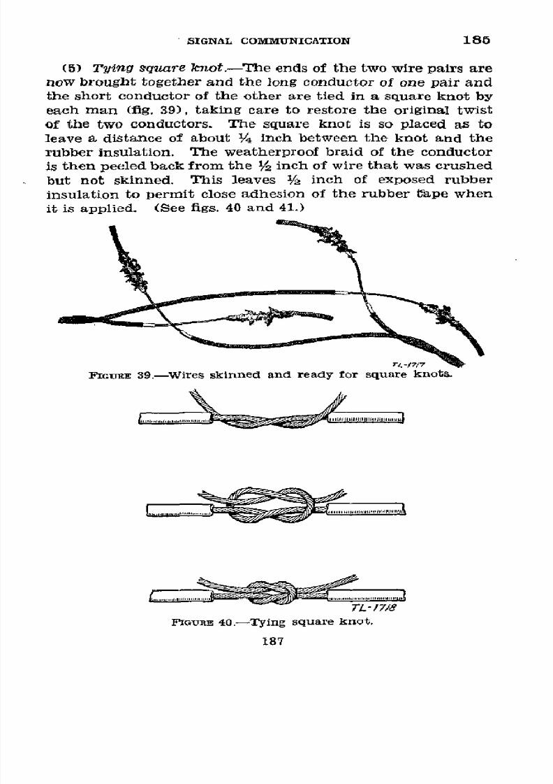
8/16/2019 (1942) FM 24-5 Signal Communication
http://slidepdf.com/reader/full/1942-fm-24-5-signal-communication 191/383
SIGNAL COMMUNICATION
185
(5) Tying
square
knot.-The
ends of the
two
wire pairs
are
now brought together and the long
conductor
of one pair and
the short
conductor of the
other
are
tied in a
square knot
by
each
man
(fig.
39),
taking
care
to restore
the
original
twist
of the two
conductors.
The
square
knot
is so placed
as
to
leave
a
distance
of about 1/4 inch
between the
knot
and the
rubber insulation.
The weatherproof
braid
of
the
conductor
is then peeled
back
from the
1/2 inch
of wire that was
crushed
but not skinned. This leaves
1/2 inch
of exposed rubber
insulation to
permit close
adhesion
of
the
rubber t^ape
when
it
is
applied.
(See
figs.
40
and 41.)
FIGUmE
39.-Wires skinned and ready
for
square knots.
TL-'1718
FIGURE
40.-Tying
square
knot.
187

8/16/2019 (1942) FM 24-5 Signal Communication
http://slidepdf.com/reader/full/1942-fm-24-5-signal-communication 192/383
185 BASIC FIELD
MANUAL
(6)
ApplZyng seizing wire.-A
6- to 8-inch
piece
of
seizing
wire
W-71 is
inserted
up through
the square
knot
and
then
the knot is
pulled
tight
(fig.
41). Seizing wire can
aZways
~~~/
rr~TL-/7/s
G:uaE 41.-Seizing wire inserted
through knot.
be improvised
by
using
a copper
strand
from
the piece
of
wire cut
off
when staggering the splice.
The seizing wire is
bent
so
as to have
half
for
wrapping
to
the
left and
half for
wrapping
to
the right. Two or three
close turns are taken
with the
seizing
wire,
both
to
the
left and to the
right
of
the
square
knot
(fig. 42),
to
bind
the
ends
of the
knot
before
Cut tail flush
with
rubber insul/otion
TL
-1720
IGURE
42.-Wrapping
seizing
wire.
cutting
off the
excess
ends
of the conductors flush
with the
rubber
insulation. The
seizing
wire
wrap
is then continued
both left
and right
of the square
knot
until
two
turns
are
taken
on the
rubber insulation
(fig.
43).
The ends of
the
rub 2
turns on
rubber
TL -1725
GTuREE
3.-Splice
on
one
conductor after seizing
is
completed.
188

8/16/2019 (1942) FM 24-5 Signal Communication
http://slidepdf.com/reader/full/1942-fm-24-5-signal-communication 193/383
SIGNAL
COMMUNICATION
185-186
seizing wire are now cut
off
flush and pressed down.into
the
rubber. With both
men
tying
the
square
knots and applying
the
seizing wire
at
the same
time,
the
over-all time for these
operations
should be
about
1
minute
(fig.
44).
Tape
the
splice
as described in paragraph 187b.
_' 1
iGaraE
44.-Splice ready
for taping.
c. Splicing
wire
W-130 and
other
fleld
wire
withot
seizing
_vtre.-To
splice
wire W-130 and other fleld wire without seiz-
ing wire, cut off one conductor of
each pair
a
pllers'
length
(about 6 inches) from
the
end.
Slip back about 3 inches
of
the
rubber
insulation
from
each conductor
by
holding the
pliers as
shown
in
figure
38, clamping the jaws
lightly
and
drawing the
pliers toward
the end
of the wire. The remain-
ing
3
inches of
insulation
on
the
end
of
the
conductor
keeps
the
strands
from fraying.
Tie
a
square knot in one
wire;
then
cross
the left-hand short end
over
the crest of the knot,
wrapping several turns closely over the bared part
of the
right-hand
conductor
and two or three turns over the
rubber
insulation. Cut
off
the
excess flush
with the
wire (fig.
45).
Repeat with the
right-hand
short end,
again
crossing
the
crest
of
the
knot
and
wrapping
the
left-hand
conductor.
The other wire
of the
pair is
tied
in the same manner. Tape
the
splice
as
described in paragraph 187b(1). This splice
will not
loosen
when
tension on the
wire
is
relieved
and has
adequate electrical
conductivity.
It
186. SPECIAL W1RE
SPLICES.-a.
Western Union
splice
(fig.
46).-The
Western
Union
splice
is used in
splicing
two solid
conductor
insulated wires. To make the splice, strip the in-
sulation
from
the
end
of
each
wire
for
a
distance
of
about
8
inches and clean the wires
so
that they
are
bright and
free
from
corrosion. Twist
the
bare ends
together in the
center
for
about
21/2 inches. Then bend the
ends
at
right
angles
to the axis of the wire and wrap each end around
the
wire
with
at
least
five close turns.
The
twisted part of the
splice
556773'-43--13
189

8/16/2019 (1942) FM 24-5 Signal Communication
http://slidepdf.com/reader/full/1942-fm-24-5-signal-communication 194/383

8/16/2019 (1942) FM 24-5 Signal Communication
http://slidepdf.com/reader/full/1942-fm-24-5-signal-communication 195/383
SIGNAL
COMMUNICATION
186
is
called
the
"neck",
and
the
five turns
at each
end
are
called
the
"buttons."
Cut off
the
ends
as
close
as possible,
being
careful
not
to leave
a
sharp
point
that
will
puncture
the
tape
wrapping.
(See
par.
187b(2)
for
taping
this
splice.)
b.
Combination
splice
(fig.
47).-The
combination
splice
is
used
to
splice
a stranded
conductor
insulated
wire
to a
solid
conductor
insulated
wire.
To
make
the
splice,
strip
the
in-
sulation
from
the
end
of each
wire
for
a distance
of
about 6
inches
and
clean
the
wires
so
that they are
bright
and
free
from
corrosion.
Tie
an
overhand
knot
in the
stranded
wire
close
to
the
insulation and
slip
it
over
the
solid
wire
to
within
'/2 inch
of the
insulation.
Pull
the
knot tight
and
wrap the
end
of the stranded
wire
around
the
solid wire
from
the
knot
to
the insulation.
Cut
off
the
surplus
stranded
wire.
Bend
the end
of
the
solid wire
back
at
the
knot
and
with it seize
the
stranded
wire,
wrapping
it up
as far
as the
insulation.
Wrap the
solid
wire in
the
direction
opposite
to the
wrap-
pings
of
the stranded
wire,
otherwise
the
solid
wire
will
fail to
SOLIO
CONDUCTOR
w/aEj
JAT
EAST
T oI
5Aa'
AT LEAST OF
BARE
W/RE V EACN
END
BEFPORE
TYVNG
NO
SPACE
LEFT
ESETWEEN
ADJACENT
TURN5
\ENO OFTTANDEO
WIRE
/TURINS
EXTENO OTV7-O
NSULATION
T3B
END OF SOLIOD
ONDUCTOR
W/RE
GcuaE
47.-Combination
splice,
solid
to stranded
conductor.
191
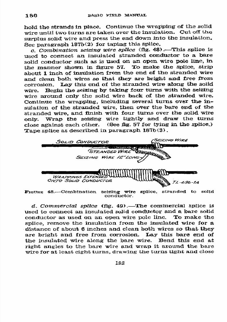
8/16/2019 (1942) FM 24-5 Signal Communication
http://slidepdf.com/reader/full/1942-fm-24-5-signal-communication 196/383

8/16/2019 (1942) FM 24-5 Signal Communication
http://slidepdf.com/reader/full/1942-fm-24-5-signal-communication 197/383
SIGNAL COMMUNICATION1
186
Sd/OD
B44RE
WH4R
*4E
ENVD
/NSULAmED
So4D
CONDUCTOC
'AND AT R/6w-iT~
T 698 A
FIGURE 49.-Commercial
splice,
solid
to
solid conductor.
together. Cut
off
the surplus end of
the insulated wire.
See
paragraph
187b(3)
for taping
splice.
e.
T-splice.-The
T-splice
is
used
to splice
a
wire to
another
without
interrupting the
circuit
of
which
the
latter
is
a
part.
In
figure
50, X is the wire
in the circuit
and
Y
is the
wire
to
be connected.
In this illustration
it
is
assumed
that
after
the splice is
completed
the portion
of X to the
left
of
the
splice
will be discarded
and that
the strain
will be toward
the right.
To
make
the
splice-
Ié
iZ'rmore
....
_
x
__,_,
FIRSTSTEP
¡End
to
be discarded
< ½Jq¿aare
nof
S
SECOND
STEP
TL
1828
FIGURE
50.-T-splice.
193

8/16/2019 (1942) FM 24-5 Signal Communication
http://slidepdf.com/reader/full/1942-fm-24-5-signal-communication 198/383
186-187
BASIC
FIELD MANUAL
(1)
Remove
about
11/2 inches of
insulation from each
of
the
conductors
of
X,
12 or more inches
apart.
(2)
Place
Y
beside
X with
the two
ends
at one
of the
bared
places.
(3) Cut
Y
off at
the
other
bared
place, and
prepare the
ends
of
Y1 and
Y2
for splicing
as in paragraph
185b(3)
and
(4).
(4)
Tie
Y
1
to
Xi
with
a
square
knot.
To tie
this knot,
make
a loop
with the left
hand in the
bared part
of Xi;
with
the
right hand, pass
the
end
of Y1 up through
the
loop,
over
the
right side
of the loop,
under
the neck
of the
loop
over
the
left
side
of
the
loop,
and
down
through
the
loop;
draw
the
knot
tight. To
avoid
making
a "thief"
knot, be
sure that
the two
conductors
on
which
the strain is
to be placed
are
on
the
same
side of
the
loop,
otherwise
the knot
will not
hold.
(5)
Twist
Y2
around Xi
and
X2,
and
tie
Y2 to
X2 in
a
simi-
lar manner.
(6) Cut
off
the
portion
of
X to be
discarded and complete
the
splice
as
indicated
in paragraph
185b.
U
187. TAPING
SPLICES.---a.
Insulation
resistance.-Splices
are
insulated
to
provide
circuits with
transmission
characteris-
tics
substantially
independent of weather
conditions.
This
requires first
that the
insulation
resistance
of the
splice
be
maintained
at the same
level as
that
of the
rest of
the line,
and second
that the
splice
be
protected
from corrosion
and
resulting
poor
conductivity
due
to weathering.
Under
service
conditions, in
which
time
is
an
important
factor,
tapes pro-
vide
the most
convenient materials
for covering
splices.
Figure
51 shows the relative
effectiveness
of rubber and
fric-
tion
tape for
insulating
feld wire
splices. In
this
graph, the
insulation
resistance
of
new
wire is
taken
as
the standard
of
reference,
and
evaluated
at 100
percent.
The
ordinate
represents
the ratio
in percent of
the
actual
insulation
re-
sistance
of
the
given splice
covering
to
the
standard
insula-
tion
resistance
of
the uninjured
new
wire.
The
abscissa
represents
the
time of
continuous
immersion
of the splices
in
water.
As
is
evident from
figure
51,
the insulation
resist-
ance of all splice coverings
is
lowered with increase
in
time of
immersion
of the
samples. However, the rate at which
the
resistance
decreases
varies
between
wide limits
for
the
various
194

8/16/2019 (1942) FM 24-5 Signal Communication
http://slidepdf.com/reader/full/1942-fm-24-5-signal-communication 199/383
SIGNAL COMMUNICATION 187
00oo
IN90SULAr/ION R£S/STANCE
90o of
/£FREtLoIRE SPLICES
60
70
30rictin
o
/Z.
aYer
Rabber7
_
O0 ayerFHction7bp
- __
lo Z4a7'e/'s
,4t0ioo
_,5
O
zo
40 60 80 10 120
140160
/MMERS/ON 7TMAE
IN
HOURS rL.o4,O
IGommE
51.-Insulation
resistance
of fleld
wire splices.
combinations
of insulation. The standard
field
wire
splice
in-
sulation
consisting of
twvo
layers of rubber
tape
and
two layers
of friction tape, decreases
50
percent in
insulation
resistance
in
29
hours.
After
160
hours
immersion
(approximately
1
week),
the resistance
is of
the order of 12 percent of standard.
In contrast,
the
same
splice
insulated
with only
two
layers
of friction
tape drops
to
50
percent
of its
original
insulation
in 2
hours, and becomes practically useless as an electrical
insulating medium
in
a
matter
of
5
hours. A
splice
covered
with one
layer of rubber and
one
layer of friction tape
is
but
little better than
one insulated with
friction tape
alone.
195

8/16/2019 (1942) FM 24-5 Signal Communication
http://slidepdf.com/reader/full/1942-fm-24-5-signal-communication 200/383
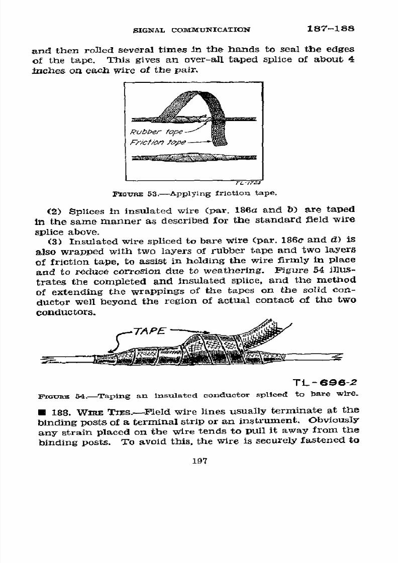
8/16/2019 (1942) FM 24-5 Signal Communication
http://slidepdf.com/reader/full/1942-fm-24-5-signal-communication 201/383
SIGNAL
COMMUNICATION
187-188
and
then
rolled
several
times
in
the
hands
to
seal
the
edges
of
the
tape.
This
gives
an
over-all
taped
splice
of
about
4
inches
on
each
wire
of
the
pair.
Rubber
te
FrCtPon
a1
e
T
-1723
F'~onE
53.-Applylng
friction
tape.
(2)
Splices
in
insulated
wire
(par.
186a
and
b)
are
taped
in
the
same
manner
as
described
for
the
standard
field
wire
splice
above.
(3)
Insulated
wire
spliced
to
bare
wire
(par.
186c
and
d)
is
also
wrapped
with
two
layers
of
rubber
tape
and
two
layers
of
friction
tape,
to
assist
in
holding
the
wire
firmly
in
place
and
to
reduce
corrosion
due
to
weathering.
Figure
54
illus-
trates
the
completed
and
insulated
splice,
and
the
method
of
extending
the
wrappings
of
the
tapes
on
the
solid
con-
ductor
well
beyond
the
region
of
actual
contact
of
the
two
conductors.
TAPE
TL- 696-2
PrGiRie
54.-Taping
an
insulated
conductor
spliced
to
bare
wire.
O
188.
WIRE
TES.-Field
wire lines
usually
terminate
at
the
binding
posts
of
a
terminal
strip
or
an
instrument.
Obvlously
any strain
placed
on
the
wire
tends
to
pull
it
away
from
the
binding
posts.
To avoid
this,
the
wire
is
securely
fastened
to
197

8/16/2019 (1942) FM 24-5 Signal Communication
http://slidepdf.com/reader/full/1942-fm-24-5-signal-communication 202/383
188
BASIC FIELD
MANUAL
a
convenient
tree, pole, or other support
before
connecting
it
to the
binding
posts.
Wire
lines are also
tied
in
at various
points
along
the
route where it is
necessary
to
hold the wire
in
place.
Several
kinds
of
ties
which
should
meet
all
condi-
tions in field
wire
line
construction
are
described below.
Where the
wire is tied above
equipment
to
which it
is
to
be
connected,
such as
a
telephone or terminal strip, a
drip
loop
is
made in the
wire.
(See
figs.
55
and
56.)
/
~~~~J......
lDripoop
za88 S
c
i 1`
TL-671
Ib,
FIcG~E
55.-Field
telephone installed in
a tent.
:Dr/l S 0o
fROM T'lS
PO/NT
TL-701
FGor 56.-Drip
loop in wire
leading
to
a
terminal
strip.
Water
running down the
wire will
drip
off
from the
bottom of the
loop and
will
not
be
led
to the terminal strip
or instrument
where
it
might
cause
a
short
circuit
or damage the equipment.
198
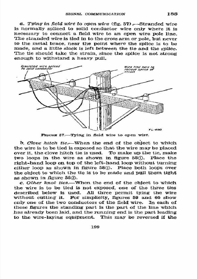
8/16/2019 (1942) FM 24-5 Signal Communication
http://slidepdf.com/reader/full/1942-fm-24-5-signal-communication 203/383
SIGNAL COMMUNICATION
188
a.
Tying in field
wire to open wire (fig.
57) .- Stranded
wire
is normally spliced
to
solid
conductor wire only where it
is
necessary to connect a field
wire to
an open
wire
pole
line.
The
stranded
wire
is
tied
in
to the
cross
arm
or
pole,
but
never
to the metal brace, near the point where the splice is to be
made, and
a little
slack
is left between the tie
and the splice.
The tie
should
take the strain, since the splice
is not
strong
enough to
withstand
a
heavy
pull.
I/nsulated
w/re
p/,ced Wire
tied
here to
to
ao/d
conducior
re/icve
sp/,ce of
rL-69o
FliG~ 57.-Tying in
feld
wire to open wlre.
b.
Clove hitch
tie.-When
the end of the object
to
which
the
wire
is
to
be
tied
is
exposed
so
that
the
wire may
be
placed
over it, the clove hitch tie
is
used.
To
make up the tie, make
two
loops in the wire
as shown
in
figure
580.
Place
the
right-hand loop on top
of
the
left-hand
loop without turning
either loop
as
shown in
figure
580.
Place both loops over
the
object
to which the tie is to be made and pull them tight
as shown in
figure
580.
c.
Other icnot
ties.-When
the end of
the
object
to
which
the wire is to be tied is not exposed,
one
of the
three
ties
described
below
is used.
All three
permit tying the wire
without cutting it. For simplicity, figures 59 and 60 show
only
one
of the two
conductors of
the field
wire. In
each
of
those figures the standing part is the
part
of
the line which
has already been laid, and
the running
end
is the part
leading
to
the wire-laying equipment. This may
be reversed
if the
199

8/16/2019 (1942) FM 24-5 Signal Communication
http://slidepdf.com/reader/full/1942-fm-24-5-signal-communication 204/383
188
BASIC
FIELD MANUAL
rL-/t1738A
PEiFro
58.-Clove hitoh
tie around
a stake.
strain
is
in
the other direction.
A bight is a loop
formed on
the wire
so
that the
two
parts
of
the
loop lie alongside
of
one
another.
(1)
Loop
knot
tie.-This
is
made more
easily
and
quickly
than
are those described
in (2)
and
(3)
below
but
it is not
so
secure. Consequently, it
is not used
in very long spans,
at
overhead
crossings where increasing
sag
resulting from
slip-
ping
of the tie might
endanger traffic,
or where it
might be
untied accidentally
by passing personnel, vehicles,
or animals.
(a)
1. To make
the tie,
stand
facing
the object on the
side
on
which the
wire
is
being laid.
Pull in enough
200

8/16/2019 (1942) FM 24-5 Signal Communication
http://slidepdf.com/reader/full/1942-fm-24-5-signal-communication 205/383
SIGNAL COMMUNICATION
188
slack
to make a bight to
go around the
object
with about 2
feet
of
bight left
over. If,
during
tying, the greater strain is on the standing part,
place
the bight around the
object from
the
front, going
around the
side toward
which the
wire is being laid, and returning to the front on
ithe side from which
the
wire has been laid (fig.
590). (If the greater strain
is
on
the
running
end,
place the bight around
the
object fron,
the
front in the opposite direction.) Bring the
bight
under and
then
c7er
both
the
standing
part and the running end,
forming
the front
V-opening shown in figure 590. Reach through
this
opening and pull through it
about
6 inches
of the
doubled
bight as
shown in figure
59Q.
Tighten
the tie, being
sure that
it
rests against
the object.
2. An alternate satisfactory
loop
knot tie may also be
made
as
follows: After
placing
the
bight around
the object
(fig. 59)),
hold the bight in
the
left
hand,
passing
the
right
hand under
the standing
part and running
end,
and
grasping
the bight
with the
right
hand
palm
up (fig. 59)), turn
the
hand
in
a
counterclockwise direction,
pull-
ing
the loop under the
standing
part
and
run-
ning
end
(fig.
590);
double
the
bight and
pass
it over
the line and into the
loop,
pulling
the
bight until the knot
is
tight and against the
object (fig.
59)).
(b)
To untie
the tie, pull
the free end
of
the
bight
through
the
opening. The
wire will
fall away
from the
object.
(2)
Square knot and loop
tie.- This tie is
used
in long
spans,
at
overhead
crossings,
and
when
a
tie
is
desired
which
will
remain
secure for a longer time
than
the
one described
in (1) above.
(a) To make the tie, begin as in
(1)
(a)
1 above,
but bring
the
bight over both the standing
part
and the
running
end,
and
then
between
the object and the
turn
around it, as shown
in
figure
600.
Draw
this knot tightly against
the
object.
Bring
the
bight
over
the
running end,
forming the
opening
201
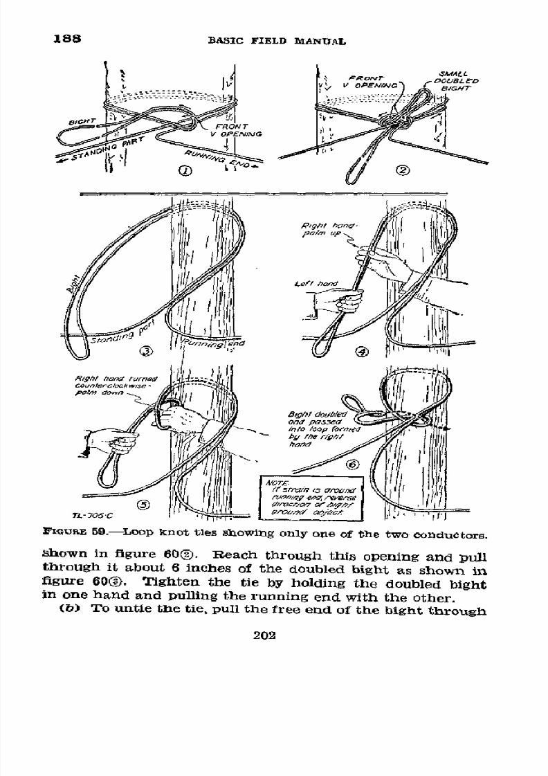
8/16/2019 (1942) FM 24-5 Signal Communication
http://slidepdf.com/reader/full/1942-fm-24-5-signal-communication 206/383
188
BASIC
FIELD
MANUAL
sMALL
,PROr
oousa-o
Y4
~ ~
VI
PENINO
1
y
/R/gh
ona
vrneegpt
hanum
Ip~p
1
n
.
/IO
T/.-
705.C
:' GUC
59.-Loop
knot
ties
showing
only one
of
the
two
conductors.
shown
in
ñgure
60(®).
Reach
through
this
opening
and
pull
through
it
about
6
inches
of
the
doubled
bight
as
shown
in
figure
60)/
Tighten
the
tie
by
holding
the
doubled
bight
in
one
hand
and
pulling
the
running
end with
the
other.
(b)
To
untie
the
tie,
pull
the
free
end of
the
bight
through
202
IOldm~
202

8/16/2019 (1942) FM 24-5 Signal Communication
http://slidepdf.com/reader/full/1942-fm-24-5-signal-communication 207/383
SIGNAL
COMMUNICATION
188
3
-A-
0
@M0
A
Sfand,ñg pan
T
f strain-/a
aroundAunnp/tg
ear
t
B-Running end
reverse
diecti,~
of ight around
object
7-/724-a
MIGaRE
60.-Square
knot
and
loop
tie,
showing
only one
of the
two
conductors.
the
opening
and
then
untie
the bight
from
the
object. The
wire
will
fall away
from the
object.
(3)
Square
]knot tie.-This
tie
is used when
a
tie
is
desired
which will
remain secure
for
a longer time
than those
de-
scribed in (1) and (2) above.
(a)
To make the
tie, proceed as in
(2)
(a)
above
but
pull
the end
of the bight through
the
opening
and
tighten it
by
holding the end
of
the
bight
in
one
hand
and Pulling
the
running end with
the other. It is
shown
in
figure
78.
(b) To
untie
the
tie,
reverse
the
procedure
in
(a)
above.
After it
has
remained in
place for some time
under a strain,
it
is more difficult
to untie
than
are the ties
described in (1)
and
(2)
above.
d. Knob tie
(fig.
61).-The
knob tie
is
used
in
tying field
wire to
a
knob
or
insulator.
It
is not
suited
to tie over
larger
objects. To
make the tie,
form a loop in the
wire.
Separate
the
two
conductors
in
the
loop and bend each
back around its
side
of
the
length
of wire so that
they
again
touch
each other
180
°
opposite
the
original position
of the loop.
Place
the
loop
over the
knob and draw
it
tight.
e. Marline tie.-The
marline
tie may be used
to
support
a
field
wire line
on a knob, cross
arm, or other support
when
there
is a possibility
that
the object
to
which
the wire
is to
be
tied
might
damage
the insulation.
To make
the
tie,
take
a
203

8/16/2019 (1942) FM 24-5 Signal Communication
http://slidepdf.com/reader/full/1942-fm-24-5-signal-communication 208/383
188-189
BASIC
FIELD MANUAL
L- 706A
FIGRE
l61 -Knob
tie.
pÑiece
of
marline which, when
doubled,
will
reach from
the
wire
in
its
suspended position
twice
around
the
support
and
down
to the wire
again, with
about
4
inches left over for
tying. Insert the ends through the
loop
formed in the middle
of the marline and draw
the
marline
tight around the wire
as
shown
in
figure 62(.
Pass
the doubled marline twice
around the support and back to the wire as shown
in
figure
62®. Tie
it
securely to the
wire
with
a
double overhand knot.
To
tie
this
knot,
place
the
marline
around
the
wire
and
pass
the running
ends over
the
standing
part to form a
loop. Then
pass the running
ends
down through
this
loop
as
shown
in
figure 62®. Draw the knot tight.
O 189. CIRCUIT MARIRKNO TAGS.--. A
field wire
circuit
is iden-
tified by means of the
designation
(par.
168) appearing
on
the
tags tied
to
the wire.
The
tags
(fig. 63)
should be
of
rope
stock
or
other
fairly
waterproof
substance
which
will
show
the marks made by a soft pencil or crayon. Short lengths of
soft
iron wire
passed through
the
eyelets of the tags
are
provided for
attaching them firmly
to wire lines, but in
such a
manner
that
they
can easily
be
removed when the line
is taken up.
Tags
are
required where the wire
line
connects
to an instrument
or terminal strip,
and
are
attached about
1
foot
from these
devices.
They
are also placed
at frequent
204
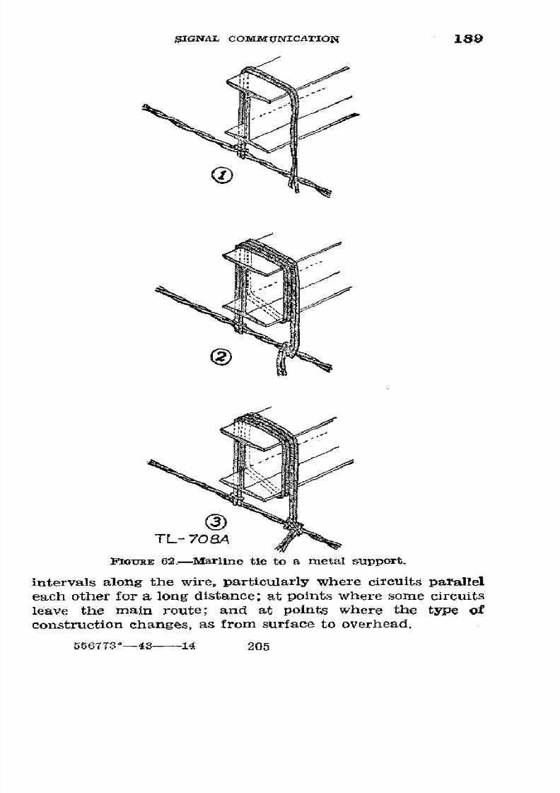
8/16/2019 (1942) FM 24-5 Signal Communication
http://slidepdf.com/reader/full/1942-fm-24-5-signal-communication 209/383
SIGNAL COMMUNICATION 189
TL-
708A
iGURmE
62.-Marline
tie
to
a
metal support.
intervals along
the
wire, particularly
where
circuits
parallel
each other
for
a long distance;
at
points where some
circuits
leave
the main
route;
and at points
where the
type of
construction changes,
as from surface
to overhead.
556773°-43
14
205

8/16/2019 (1942) FM 24-5 Signal Communication
http://slidepdf.com/reader/full/1942-fm-24-5-signal-communication 210/383
189-190
BASIC
FIELD
MANUAL
5sof
Wire
101 PEARL
TL-7t0A\
FZiGoE 63.-Circuit
marking tags.
b.
Trunk
circuits in
units
larger
than
the
division
are
tagged
with the complete designation
of the circuit.
In
smaller
wire systems,
the circuit
number is followed
by
the
title of the organization constructing the circuit.
Local
tele-
phone
circuits
are tagged with the
local
telephone number.
Telegraph legs are tagged
with
their
local
number and the
unit to which
they
lead, as TG-1 to 1st CT, TG-2 to 2d
CT,
etc.
c.
Commanders
will
prohibit any tagging of circuits
that
clearly
indicates
to
anyone unacquainted
with the confiden-
tial
system
employed,
the specific
units which
the
circuits
serve
and
some means
of
identification such as
colored
or
partially
colored tags, tags having distinctive
shapes, or
a
code name
prescribed by
higher authority
will
be substituted.
If
colors
are
used,
care
must
be
taken
that
they
will be
iden-
tiflable at
night
with
available light sources.
An example
of
a wire
tagging
code is given in paragraph
265n.
h 190.
TERMINAL
STRIPS.-a. Description.-A
terminal
strip is
a block
of insulating material to which
are
fastened several
binding
posts.
The binding posts are
connected
in pairs by
metal strips, so that a wire connected to a binding
post
on
one
side
will be
joined
electrically
to
another
wire
connected
to
the
corresponding
binding
post on the
opposite
side. The
type commonly used
for
fleld wire systems
is
the terminal
strip TM-84-A which will hold five pairs of wires (see fig.
64).
b. Connecting a wire to
a
terminal strip (fig. 65).-To make
the
connection,
skin off about /2
inch
of.insulation
from the
end of the wire to
be connected.
Open the slot in the binding
post to its
fullest
extent by unscrewing the
knob
with the
206

8/16/2019 (1942) FM 24-5 Signal Communication
http://slidepdf.com/reader/full/1942-fm-24-5-signal-communication 211/383
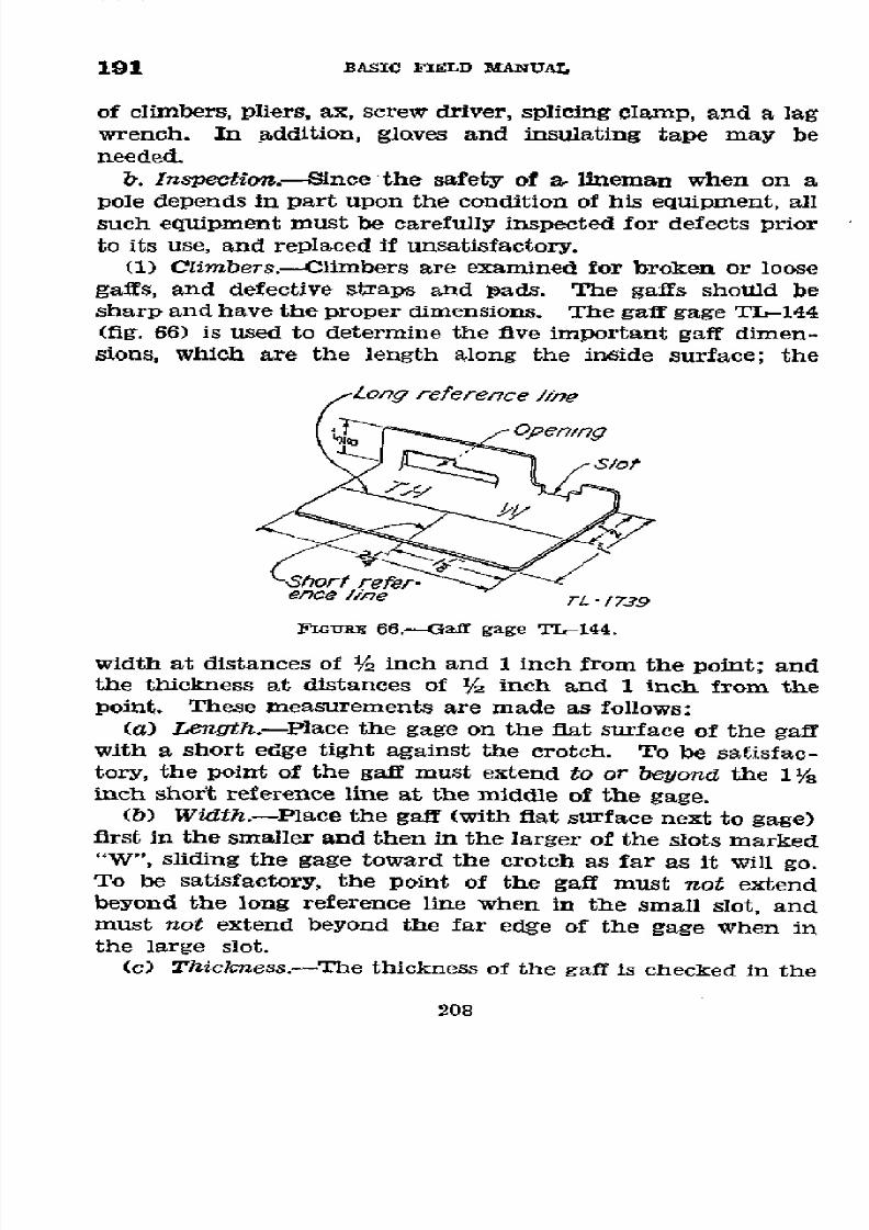
8/16/2019 (1942) FM 24-5 Signal Communication
http://slidepdf.com/reader/full/1942-fm-24-5-signal-communication 212/383
191
BASIC
FIELD
MANUAL
of
climbers,
pliers,
ax,
screw
driver,
splicing
clamp,
and a
lag
wrench.
In
addition,
gloves
and
insulating
tape
may be
needed.
b.
Inspecton.-Since
the safety
of
a, lineman
when
on
a
pole
depends
in part upon
the
condition
of his
equipment,
all
such
equipment
must
be carefully
inspected
for
defects
prior
to its
use,
and
replaced
if
unsatisfactory.
(1)
Climbers.-Climbers
are
examined
for broken
or loose
gaffs,
and defective
straps
and pads.
The
gaffs should
be
sharp
and
have
the
proper
dimensions.
The
gaff
gage
TL-144
(fig.
66)
is
used
to
determine
the
five
important
gaff
dimen-
sions, which
are
the
length along
the inside
surface;
the
;ong
reference
/ne
Opening
Seortf
efer-
ence
/ine
rL -1739
FGIuRE
66.--Gaff
gage
TL-144.
width
at
distances
of
1/2
inch and
1 inch
from
the
point;
and
the
thickness
at distances
of
1/z
inch
and 1
inch
from
the
point.
These
measurements
are
made
as follows:
(a) Length.-Place
the
gage
on the
fiat surface
of the
gaff
with a
short
edge
tight
against
the
crotch.
To
be
satisfac-
tory, the
point
of the
gaff
must extend
to or
beyond
the 1
/8
inch
short
reference
line
at
the middle
of
the gage.
(b)
Width.-Place
the
gaff
(with
fiat
surface
next to
gage)
first
in the
smaller
and
then
in the
larger
of
the
slots marked
"W",
sliding
the
gage toward
the crotch
as
far
as
it will
go.
To
be
satisfactory,
the
point of
the
gaff
must
not
extend
beyond
the
long reference
line
when
in
the
small
slot,
and
must
not
extend
beyond
the
far edge
of
the gage
when
in
the
large slot.
(c)
Thickness.-The
thickness
of
the
gaff
is
checked
in the
208

8/16/2019 (1942) FM 24-5 Signal Communication
http://slidepdf.com/reader/full/1942-fm-24-5-signal-communication 213/383
SIGNAL
COI%[MUNICATION
191
same manner as
the width,
using
the
openings
marked
"TH."
(2) Lineman's
belt.-The
lineman's body belt and safety
strap
are
examined before
use
for cracks, cuts,
tears,
broken
stitching, worn places, loose rivets,
or other defects that
would be likely to affect the strength of the leather.
Buckles,
snaps,
keepers, and D-rings should likewise
be
inspected for
defects
and wear.
c. Care of equipment.-(1) Climbers.-The
gaffs
of
climb-
ers are kept clean,-free from rust, and sharp at all times.
Sharpening is preferably
done by clamping the climber in
a
vise
and
filing
fiat
on
the
inside
surface
of
the
gaff,
thereby
keeping
the
shape
of the gaff unchanged.
After
sharpening,
the
gaff dimensions are
checked
as described
in
b(1) above.
Climbers when
not in use are
given
a
light
coating
of
oil
to
prevent
rust, and
must not be
stored in
the
same
container
with body belts
and safety
straps to, avoid
any possibility of
cutting
or puncturing
the leather equipment.
(2)
Leather
belts.-The
body
belt,
safety
belt,
and
climber
straps
are kept
clean,
soft,
and
pliable
by
the
use of saddle
soap or by
washing
thoroughly
with the lather from
a neutral
soap
(such
as
castile), removing embedded dirt
and
perspira-
tion, wiping dry,
and
finally sparingly
oiling
with neat's-foot
oil.
Mineral oil
or grease should not be
used for
this purpose.
Particular
care
must
be
taken not
to subject
the leather to
excessive
heat
by standing near an open fire, hanging the
belt
on
or
near
hot
steam
pipes,
or
contacting
hot
objects.
Fur-
ther instructions on the
care of
leather may be
found in
AR
30-3040.
d.
Size
and adjustment.-(1) The size
of
climbers
is de-
termined bY the
measured
length
in
inches
from
the instep
to the end
of the
leg iron.
The
correct
size of climber to use
is
one
measuring /2 inch
less in length than the
distance
from the
projecting bone on the inside of
the knee to the
arch
of
the
shoe
of
the
wearer.
Climbers
are
bent
to
conform
to
the wearer's leg so that
they are
comfortable, with straps
fastened snugly around the calf and ankle.
(2) The D-rings of
the
lineman's
body
belt
of proper size
will
be
just behind
the prominent portions of the
hip
bones.
Wear
the body
belt
over the hips
and
tightly enough
not
to
209
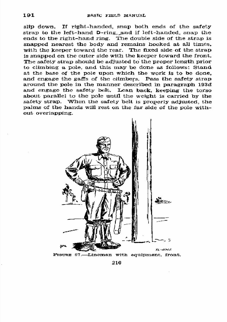
8/16/2019 (1942) FM 24-5 Signal Communication
http://slidepdf.com/reader/full/1942-fm-24-5-signal-communication 214/383
191 BASIC
FIELD
MANUAL
slip
down. If
right-handed, snap both ends of the
safety
strap
to the left-hand
D-ring,and
if
left-handed,
snap the
ends to the
right-hand
ring. The double side
of
the strap is
snapped
nearest
the
body
and remains
hooked
at
all
times,
with the keeper
toward the rear. The
fixed
side of the strap
is snapped on the outer side with the keeper toward the
front.
The safety strap should be
adjusted
to the proper length prior
to climbing a
pole,
and this may be done as follows:
Stand
at the base of
the
pole upon which the work is to be done,
and
engage the
gaffs
of the
climbers. Pass
the
safety strap
around
the
pole
in
the manner
described
in
paragraph
193d
and engage the safety
belt.
Lean back, keeping the torso
about parallel to the
pole
until the weight
is
carried
by
the
safety
strap.
When
the
safety belt is
properly adjusted,
the
palms
of the hands
will rest
on the
far
side of
the
pole
with-
out
overlapping.
FIGURE
67.-Lineman
with
equipment,
front.
210

8/16/2019 (1942) FM 24-5 Signal Communication
http://slidepdf.com/reader/full/1942-fm-24-5-signal-communication 215/383
SIGNAL
COMMUNICATION
192
* 192. POLE
CLIMBING
SAFEGUARDS.-a. On the ground.-Men
wearing
climbers
must
exercise caution at all times since
gaffs
will easily penetrate shoes,
muscles,
and
bone,
and are capable
of
making
very
serious
wounds. Every
precaution
must
there-
fore
be taken
to avoid stepping
on the feet of personneL
Climbers should be worn only while climbing and working on
poles.
Habitually
wearing
climbers while working
on
the
ground will
inevitably
result in serious injury
to
personnel.
While
standing
on the
ground,
a lineman stands in
the
posi-
tion
shown in figures
67 and 68,
with feet
well
separated
and
hands
on
hips.
b. Aloft.-While aloft,
linemen always use
their
safety belts,
not only to prevent falls
but
also to facilitate working with
minimum fatigue. Linemen must be careful not to drop
tools
or other equipment
while
on
a pole, as these objects may
strike
personnel
working
below.
TL-4a43
IGunE
68.-Lineman
with
equipment,
rear.
211
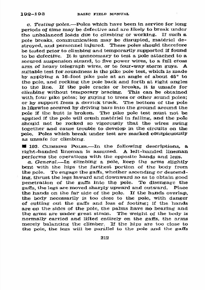
8/16/2019 (1942) FM 24-5 Signal Communication
http://slidepdf.com/reader/full/1942-fm-24-5-signal-communication 216/383
192-193
BASIC
FIELD MANUAL
c. Testing
poles.-Poles
which
have been
in service for
long
periods
of time may be defective
and
are
likely
to
break
under
the
unbalanced
loads due
to
climbing
or working.
If
such
a
pole breaks,
communication
may
be
disrupted,
matériel
de-
stroyed,
and personnel
injured.
These poles should
therefore
be
tested prior
to
climbing and
temporarily supported if found
to be
defective. It is
unnecessary
to test a pole attached
to a
secured suspension
strand,
to five
power
wires,
to a
full
cross
arm
of heavy
telegraph
wires, or
to four-way
storm
guys.
A
suitable
test for soundness
is
the pike
pole
test,
which
is made
by
applying
a
16-foot
pike
pole
at
an
angle
of
about
45
°
to
the pole,
and
rocking
the pole back
and
forth
at
right
angles
to the line.
If the
pole
cracks or
breaks, it
is
unsafe for
climbing without
temporary
bracing.
This
can
be
obtained
with
four
pike poles;
by guying to trees
or
other
sound
poles;
or
by support
from
a
derrick
truck. The bottom of the pole
is
likewise secured
by
driving bars
into
the ground
around
the
pole
if
the butt is broken.
The pike pole
test
must
not be
applied
if
the
pole
will
crush matériel
in
falling, and
the
pole
should not
be rocked
so vigorously
that
the wires
swing
together
and cause trouble to
develop
in the circuits
on the
pole.
Poles which
break
under
test are marked
conspicuously
as
unsafe
for climbing.
* 193. CLIMBING
POLES.-In
the
following
descriptions,
a
right-handed
lineman is assumed.
A left-handed
lineman
performs the operations
with
the
opposite
hands
and
legs.
a.
General.-In
climbing a
pole,
keep
the arms
slightly
bent
with the hips
the
farthest
portion
of
the
body from
the pole.
To engage the gaffs, whether
ascending
or
descend-
ing, tbrust the legs inward
and
downward
so as
to obtain good
penetration of the gaffs into the
pole. To disengage the
gaffs,
the
legs are moved
sharply
upward
and
outward.
Place
the
hands on
the far side
of the pole.
If
the
hands overlap,
the
body
necessarily
is
too
close
to
the
pole,
with danger
of cutting
out the
gaffs
and
loss of
footing;
if the hands
are on
the sides of
the
pole, the
palms have no
bearing and
the
arms
are
under
great strain.
The
weight
of
the
body
is
normally
carried and lifted entirely
on
the gaffs,
the arms
merely
balancing
the
climber.
If the hips are
too close
to
the
pole,
the
legs will be
parallel
to
the pole
and
the
gaffs
212

8/16/2019 (1942) FM 24-5 Signal Communication
http://slidepdf.com/reader/full/1942-fm-24-5-signal-communication 217/383
SIGNAL COMMUNICATION 193
will cut out removing support for the climber; likewise if
the hips are too far out the arms are placed under strain
since
they
will be
supporting
a large
portion
of
the
climber's
weight.
b.
Ascending.-(1)
Before climbing,
circle
the
pole
and
inspect it for
soundness,
dangerously wide weather cracks,
soft or
other
spots
in the
wood, and location of
knots.
Notice
any cables, cross
arms, or
other obstructions that may inter-
fere
with climbing the
pole,
etc. If
the
pole
leans, select
the high
side
for climbing.
FIGURE
69.-Beginning
the
climb.
(2)
Hold
onto
the
pole
and
raise
the
left
foot
about
10
inches
from
the ground, keeping it about 1 inch
from
the pole,
and
with a downward thrust, engage the gaff of the climber
in
the face
of
the
pole
about 8 inches from
the
ground.
(3) Lift the
weight of
the body on the gaff, keeping
the
knees straight and
raising the
other leg and corresponding
213

8/16/2019 (1942) FM 24-5 Signal Communication
http://slidepdf.com/reader/full/1942-fm-24-5-signal-communication 218/383
193
BASIC FIELD
MANUAL
arm, drive
the
climber
downward
and
inward to
seat
the
gaff firmly
(fig.
70).
(4)
The
climber
is disengaged
by
a
sharp
upward and out-
ward
motion
of
the leg,
and in taking
the next
step
the
diagonal
arm and
leg are raised
together.
(5)
Reengage
the free gaff
firmly,
and so
on
to
the desired
height,
always
looking
upward.
¡G~uE
70.-Climbing.
c.
Descending.-The
motions
in
descending
are
the
re-
verse
of
those used in ascending.
Look
down to
see that the
way is clear below.
d. Working on pole.-To
fasten
the
safety
belt
when at the
desired
height on the pole-
(1)
Shift
the
weight partially
to the left
foot and
engage
the right
gaff at a slightly
higher
level than
the
left
gaff.
(2) Place the right hand around the
pole
for secure balance
214

8/16/2019 (1942) FM 24-5 Signal Communication
http://slidepdf.com/reader/full/1942-fm-24-5-signal-communication 219/383
SIGNAL
COMMUNICATION
193
(fig. 71), and
with the
thumb of the
left hand,
open
the keeper
and shift
the fixed
end
of the
safety
strap around
the pole
to
the
right hand.
(3) Transfer
the
snaphook
and
strap
to the
right hand,
and
balance the body
with the left
hand (fig. 72).
FIGURE
71.-Unhooking
safety
belt.
(4) Hold
the
strap
up
loosely
on
the
pole
at
about
the
proper
height while
the
right hand
pulls
the
belt
to
the
right-hand
D-ring.
(5)
Snap
the
hook
to
the
right-hand
D-ring,
using
the
heel of
the right
hand to
back up the ring.
It
is
essential
to SEE that
the ring
is prorperly
engaged,
and
not
merely
to
assume
from the
snap
of
the
keeper that
the
D-ring
has been
engaged
by
the
hook. (See
fig. 73.)
(6) Reengage
the right gaff at the same
level
as the left
gaff,
lean back
and
carefully
put
the
full
weight
on
the safety
215
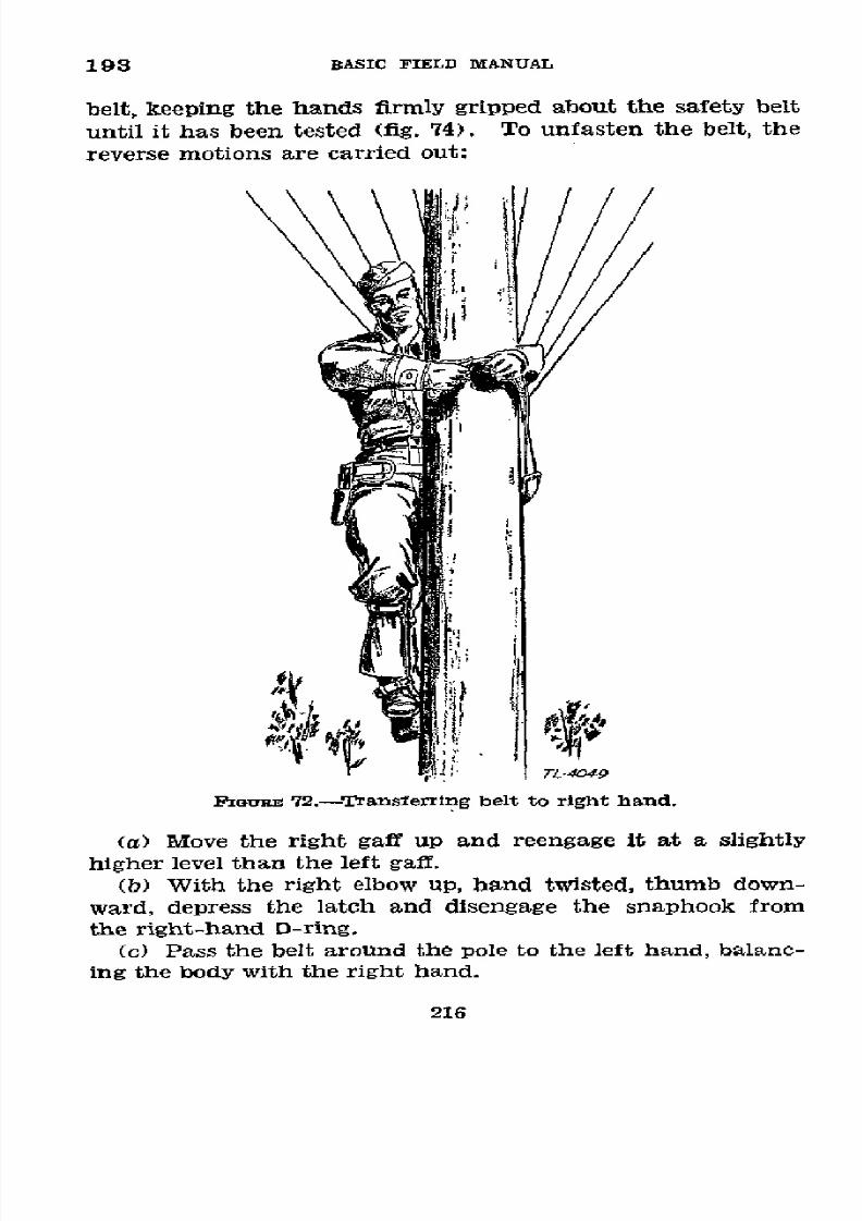
8/16/2019 (1942) FM 24-5 Signal Communication
http://slidepdf.com/reader/full/1942-fm-24-5-signal-communication 220/383
193
BASIC
FIELD
MANUAL
belt,
keeping
the
hands
firmly
gripped
about the
safety
belt
until
it
has
been
tested
(fig.
74).
To unfasten
the
belt,
the
reverse motions
are carried
out:
FIGuRE
72.-Transferring
belt
to
right
hand.
(a)
Move
the right
gaff
up and
reengage
it
at a
slightly
higher
level
than
the
left gaff.
(b)
With
the
right
elbow
up,
hand
twisted,
thumb
down-
ward,
depress
the
latch
and
disengage
the
snaphook
from
the right-hand
D-ring.
(c)
Pass
the belt
around
the
pole
to the
left
hand,
balanc-
ing
the
body
with
the
right
hand.
216
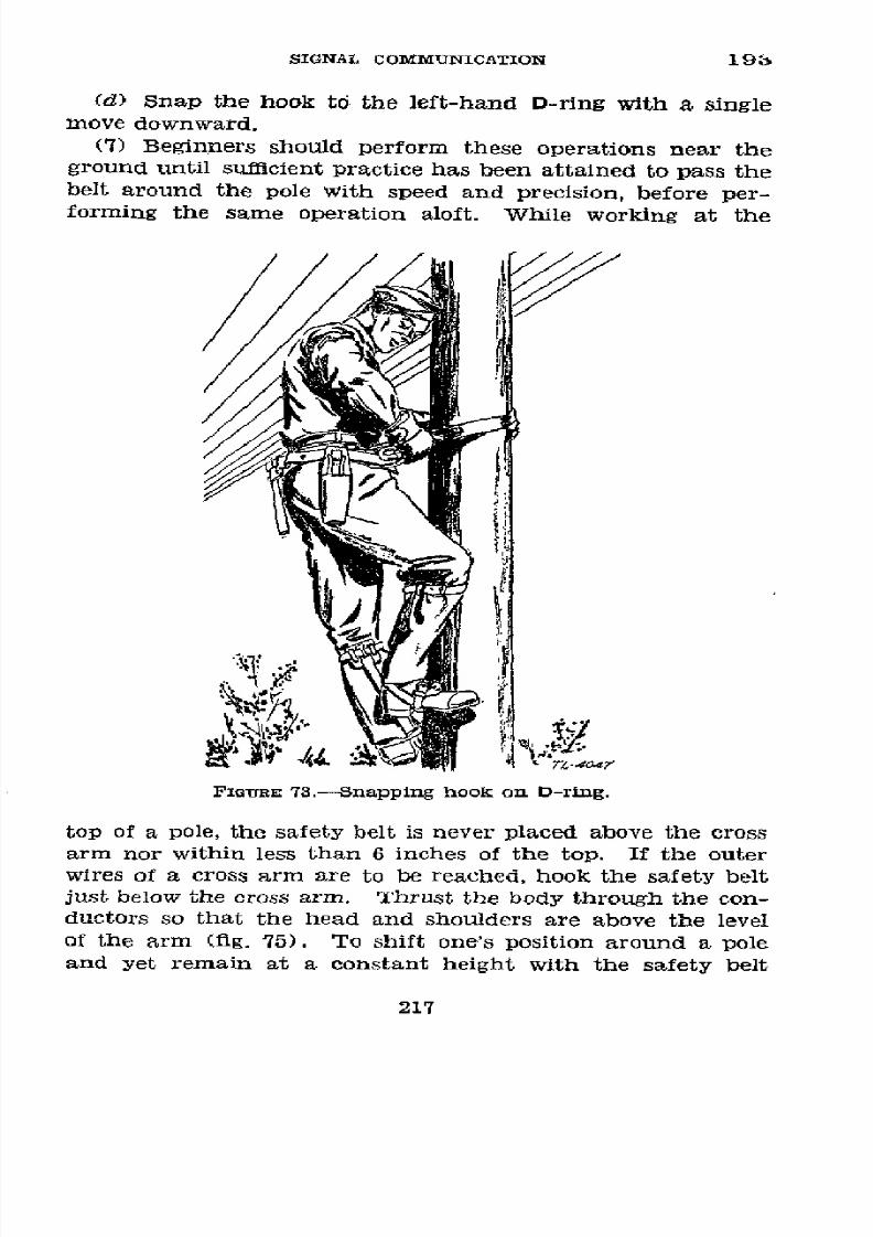
8/16/2019 (1942) FM 24-5 Signal Communication
http://slidepdf.com/reader/full/1942-fm-24-5-signal-communication 221/383
SIGNAL
COMMUNICATION
19,
(d)
Snap
the
hook
to
the
left-hand
D-rlng
with
a
single
move
downward.
(7)
Beginners
should
perform
these
operations
near
the
ground
until
sufficient
practice has
been
attained
to
pass
the
belt
around
the
pole
with
speed
and
precision,
before
per-
forming
the
same
operation
aloft.
While
working
at
the
FiaURE
73.-Snapping
hook
on D-ring.
top
of
a
pole,
the
safety
belt
is never
placed
above
the
cross
arm
nor
within
less
than
6 inches
of
the
top.
If
the
outer
wires
of
a cross
arm
are
to
be
reached,
hook
the
safety
belt
just below
the cross
arm.
Thrust
the
body
through
the
con-
ductors
so that
the
head
and shoulders
are
above
the
level
of
the
arm
(fig. 75).
To
shift
one's
position
around
a pole
and
yet
remain
at
a
constant
height
with
the
safety
belt
217

8/16/2019 (1942) FM 24-5 Signal Communication
http://slidepdf.com/reader/full/1942-fm-24-5-signal-communication 222/383
193-195 BASIC
FIELD
MANUAL
fasteied, taIe
2- or 3-inch
steps
sideward
in the
desired
direction,
twisting
the hips
slightly in the belt
each
time
so
as
to
obtain the necessary slack.
TL 400 A @
,
FIGuRE
74.-Testing
the safety
belt.
* 194. WIRE-LAYING EQUIPMENT.-Field
wire is
carried for-
ward
and
laid
by
motor
trucks
or other
vehicles, or
animals,
carrying
reel
units;
by
hand-drawn or towed reel carts; by
reels
on
axles
carried by hand; and
from bundles
or coils
carried by
hand.
The actual method employed depends upon
the equipment
available, the
condition
of
the roads
and
ter-
rain,
the amount of
traffic,
and
the
tactical situation. For
descriptions of speciflc
apparatus
employed, see appendix I.
* 195. PROTECTION
OF
WIRE.-Immediately after wire
has
been laid, it should be removed from the path of vehicles or
traffic
in order
to
protect
it and insure its
continued
use. If
the
wire-laying
device does
not
otherwise
lay
the wire in a
218

8/16/2019 (1942) FM 24-5 Signal Communication
http://slidepdf.com/reader/full/1942-fm-24-5-signal-communication 223/383
SIGNAL
COMMUNICATION
195-196
safe place,
it
must
be
followed
by
personnel
who
place the
wire
in
the desired
position
by hand,
by the use
of
wire
pikes,
or other
expedients.
IiGURE 75.--Working
on outer
wire of cross
arm.
* 196.
RECOVERY
OF WIRE.-In
the recovery
of
wire,
the re-
covering
equipment
should
be
preceded
by
linemen,
who
remove
all tags,
and with a
wire pike
or
by hand place
the
wire
back
in the
path
of
the
recovering
equipment.
Leather
gloves
or pads
should ordinarily
be
used
for protection
while
handling
field
wire.
The normal
way to
recover wire
is
to
proceed
along
the line
and wind
up the wire
en
route.
Under
some
conditions
it
may
be
necessary
to
leave the recovering
equipment
stationary
and
drag in the
wire by
turning
the
219

8/16/2019 (1942) FM 24-5 Signal Communication
http://slidepdf.com/reader/full/1942-fm-24-5-signal-communication 224/383
196-198
BASIC
FIELD
MANUAL
reel.
This
causes
more wear
on the
insulation
and
may
cause the wire to
break.
E
197.
RouTiNG
OF
WIRE
LNES.--a.
The
signal
or
communica-
tion
officer
prescribes
the
general
route
to
be
followed. The
chief
of construction
should
be
allowed
considerable
latitude
in
the
selection
of the actual
route to provide for unforeseen
terrain
conditions.
Routes must
be reconnoitered
before
wire lines are laid.
Cross-country routes
are desirable tá
minimize interruptions
resulting
from bombs, shell fire,
and
trafflc.
b.
Maintenance
is
facilitated
by
using
the
minimum number
of
routes.
However, vulnerability
of the lines
is likely to
be
increased,
and complete
interruption
of
wire
communica-
tion
may
result unless
the route
is
particularly
well
chosen.
In
general,
where
more than
one
circuit is
to be laid to a
unit,
vulnerability
may
be decreased and circuit continuity
better insured
if an
alternate
route
is
used
for the
additional
circuit.
The route or
routes
selected
are determined
largely
by the time
element
and
the
wire-laying
equipment
available,
but
should
afford cover
from
hostile
observation
and fire.
Main
traffic
routes, shelled
areas, and areas
over which tanks
or tractors
are
likely to pass
should
be avoided
wherever
practicable.
It
is also desirable that
lines should
be routed
to
permit
use by the
same
or
another
friendly
unit
after
the
movement of
command posts.
R
198. CONSTRnrCTION
ORDERS.---.
The chief of construction
is
given
orders
prescribing
the
number
of
circuits
to be in-
stalled,
the
priority
of installation,
the time
at
which
each
of the various circuits must
be
completed,
and the action to
be taken
upon
the completion
of
the installation.
He should
receive or obtain the following descriptive information
rela-
tive
to each circuit to
be
laid:
(1)
Circuit number.
(2)
Route.
(3) Whether
a trunk or
a
local circuit.
(4) Whether
a
metallic or a ground return
circuit.
(5)
Type
of wire.
(6) The centrals which it
will
connect and test stations
it
220

8/16/2019 (1942) FM 24-5 Signal Communication
http://slidepdf.com/reader/full/1942-fm-24-5-signal-communication 225/383
SIGNAL
COMMUNICATION
198-199
will
pass
through,
including the
telephone
directory
names
of
the organizations served.
(7)
Approximate
length.
(8)
Type
of
construction.
(9)
Nature
of
roads
and terrain.
(10)
Precautions to avoid
damage
by
friendly
troops and
transportation.
(11) Tests
and
reports
required.
b. This
information
is
best imparted by use of
a
line
route
map and circuit
diagram supplemented
by oral or written
in-
structions
from
the
signal
or
communication
offcer.
These
instructions
always include orders
as
to
the
disposition
of
the
construction
detail
after
the
construction
specified has
been
completed.
* 199.
PROCEDURE
IN
LAYING
FIELD
WIRE.-a. The
construc-
tion
chief makes a personal
reconnaissance
of
available
routes
before
starting the
construction.
During
this
reconnaissance
the following features of the
routes
are
noted:
(1)
Number
of
overhead
crossings.
(2)
Number of
underground crossings.
(3)
Number of railroad crossings.
(4) Number of stream crossings.
(5) Types of roads
found and the wire-laying
equipment
and
type
of construction
best
adapted to
each.
(6)
Distances
in
miles.
(7) Concealment for
wire
parties
during
construction and
subsequent
maintenance.
(8) Any obstacles
to maintenance.
(9) Alternate routes
to
avoid
gassed or
shelled
areas
or
other
unfavorable
road
conditions.
b.
The
exact route along
which
the wire
is
to
be
laid
which
offers the
least
difficulty
of construction and mainte-
nance are
then
selected.
c.
The
wire
for
the
circuits
is
tested
before
starting
to
insure
the continuity
of each reel. Reels
of
wire
which do
not show a continuous
circuit when tested are not
used
until
the
wire
has
been serviced (par. 242).
d. At the
starting
point, the free
end of the wire
is
tagged
with
the
circuit
designation
(par.
189). This
tag is placed
a
foot from the end
of
the
wire.
556773'-43-15
221
8/16/2019 (1942) FM 24-5 Signal Communication
http://slidepdf.com/reader/full/1942-fm-24-5-signal-communication 226/383
199
BASIC
FIELD
MANUAL
e. Sufficient
wire
is
left
at
the
free
end
to
reach
the
switch-
board
terminal
strip
or
other
installation,
and
the
wire
is
tied
in
to some
fixed
object.
f.
The
free
end
of
the
wire
is
connected
to
the
switch-
board
terminal
strip
if
installed.
If
a switchboard
is to
be
installed
later,
the
wire
is connected
to a
telephone
or
other
instrument
which
may
be
used
in
making
tests
on
the
cir-
cuit
until
the
switchboard
has
been
installed.
g.
The
chief
of construction
then
directs
the
laying
of
wire
over
the
detailed
route,
determined
as
in
b above,
follow-
ing
the
general
route
prescribed
by
the
signal
or
communi-
cation
officer
(par.
197).
He
causes
a test
to
be
made
back
to
the
starting
point
from
the
far
side
of
each
splice
after
it
is
made
in
order
to insure
continuity
of
the
circuit.
When
connections
are
made
at
terminal
strips
he causes
a
test
to
be
made
from
the
far
side
of
the
connection
back
to
the
starting
point.
h.
When
the
wire
has
been
laid to
the
designatedpoint,
it
is
tied
in and
tagged,
leaving
a
free
end
with
sufficient
slack
to
run to
the
switchboard
terminal
strip.
The
circuit
is then
tested
and
turned
over
to
the
operating
detail
who
connect
it
to the
switchboard
terminal
strip
or to
an
instru-
ment.
The
chief
of
construction
calls
back
over
the
com-
pleted
circuit
to
report
the installation.
This
call
is
placed
through
the
switchboard
or
other
instrument
if
installed,
so
that
any
fault
in
the
terminal
connections
may
be discovered
and
corrected
before
the
circuit
is reported.
i.
Should
the
wire
be
laid
to
any
location
where
a
switching
central
is to
be
installed,
but
where
the
operating
detail
or
the
equipment
for
the
installation
has
not
yet
arrived,
the
chief
of
construction
calls
back
over
the
circuit
in order
to
verify
his
proper
location
and
to
ask
for
instructions.
In
the
absence
of
other
instructions,
the
construction
chief
leaves
a
member
of
the
construction
detail
at
the
wire
termi-
nal
with
a telephone
connected
to
one
circuit.
This
member
informs
the
arriving
personnel
of
the
location
of the
circuits
and
assists
in
making
the
terminal
connections.
After
the
terminal
apparatus
has
been
connected,
he
makes
a
test
back
and
reports
over
each
circuit.
Sufficient
slack
is
left
at
these
terminals
to permit
extending
the
circuits
to
the
probable
222
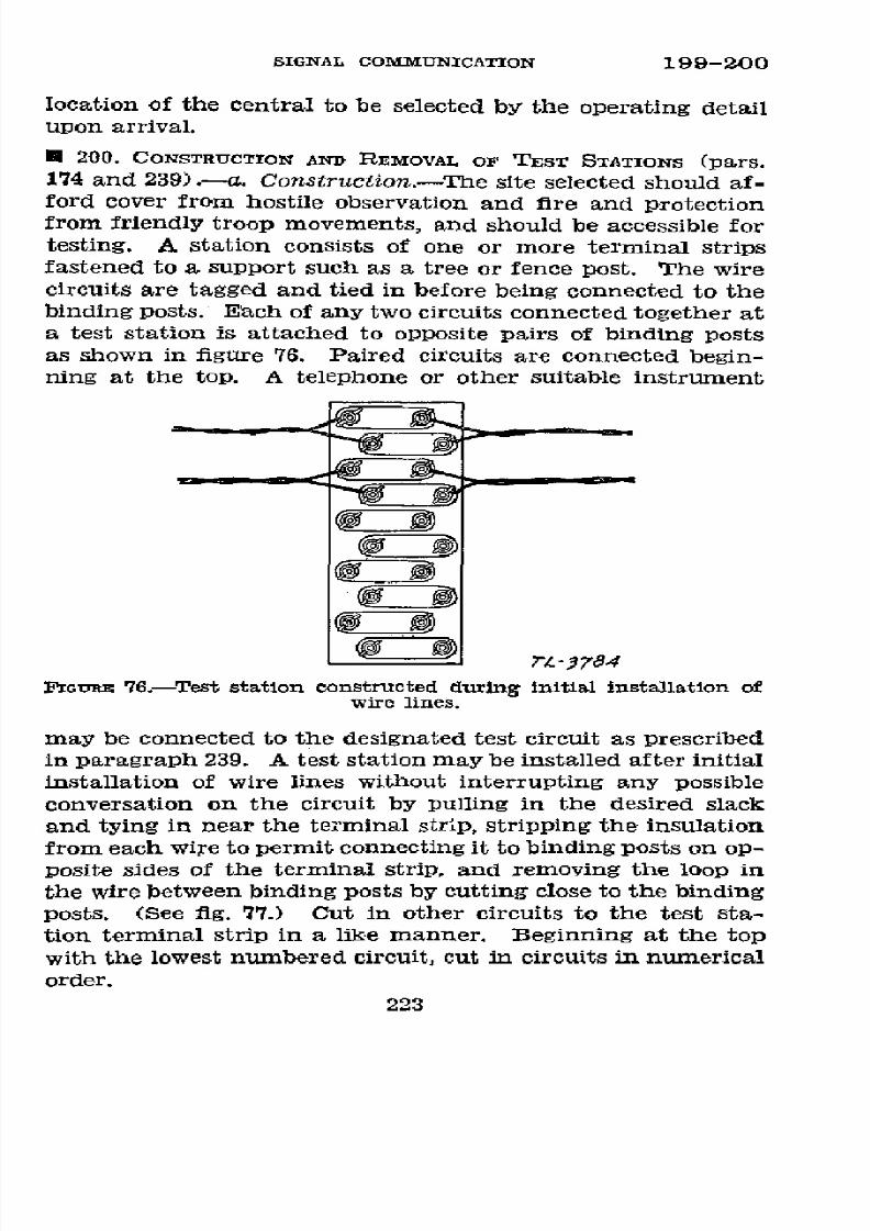
8/16/2019 (1942) FM 24-5 Signal Communication
http://slidepdf.com/reader/full/1942-fm-24-5-signal-communication 227/383
SIGNAL COMMUNICATION
199-200
location
of
the central
to
be selected
by the
operating
detail
upon arrival.
*
200.
CONSTRUCTION
AND
REMOVAL
OF
TEST
STATIONS
(pars.
174
and 239).-a.
Construction.-The
site selected should
af-
ford cover
from
hostile
observation
and
fire
and
protection
from friendly
troop
movements,
and should
be accessible
for
testing.
A
station
consists of
one
or more
terminal
strips
fastened
to
a support
such
as a tree or fence post.
The
wire
circuits
are
tagged and tied in
before being connected
to the
binding
posts.
Each
of
any two
circuits
connected together at
a
test
station
is
attached
to opposite
pairs
of
binding
posts
as shown in
figure 76. Paired
circuits
are connected
begin-
ning at the
top. A
telephone or
other
suitable instrument
r7-3784
FIGURE 76.-Test
station constructed
during
initial
Installation
of
wire
lines.
may be connected
to
the designated
test
circuit
as prescribed
in
paragraph
239. A test station may
be installed
after
initial
installation
of
wire lines without interrupting
any possible
conversation
on the circuit
by pulling in
the
desired slack
and
tying
in near the
terminal strip,
stripping
the
insulation
from each
wire to permit connecting
it
to
binding
posts on op-
posite
sides
of the
terminal strip, and
removing
the
loop
in
the wire
between
binding
posts by cutting
close
to
the
binding
posts. (See fig. 77.) Cut
in
other circuits
to
the
test
sta-
tion terminal strip
in
a like manner.
Beginning
at the top
with
the lowest numbered
circuit,
cut in circuits in numerical
order.
223

8/16/2019 (1942) FM 24-5 Signal Communication
http://slidepdf.com/reader/full/1942-fm-24-5-signal-communication 228/383
200-201
BASIC FIELD
MANUAL
b. Removal.-When
a test station
is to
be abandoned,
it is
the usual
practice to leave
the
terminal
strip connected,
al-
though
it
may
be
removed
and
the
circuits
spliced
through.
Before
removing any
circuit from
the strip, the
lineman
first
listens
on it and satisfies
himself that it is not
in
use. He
then calls
on the circuit and
notifies
the
switchboard oPerator
that
the test
station
is to be
removed
and
the
circuits cut
through.
Then,
taking
two
wires
that
are
connected
together
by
the
terminal
strip,
he removes
them
from the
binding
posts
and splices
them
together.
The
other
wires of
the pair
are
then
spliced,
and other
circuits
are
removed
from
the
strip
and
spliced
in
a like
manner.
oz-3785
FiGURE 77.-Test station
constructed after lnitial
installation of
wire
lines.
U 201.
SURFACE
LINE CONSTRUCTION.-During
movement
of
units in combat, field
wire lines are laid hastily
on the ground.
This
type
of wire line is termed
a surface
line.
Surface
lines
must
be
protected
from-traffic
at
command posts,
road
and
railroad crossings, or
other
places where the lines
cross
traffic lanes
(par. 209d). Surface
lines are laid very loosely
by
leaving
abundant
distributed slack
in
order
that
the
wire
may
be fiat on
the
ground
and sufficient
slack provided
as
incidental protection
from shell fire, for repairing
breaks
and facilitating subsequent
changes
in
the
type
of construc-
tion. At
suitable
intervals,
surface lines
are
tied in
to ob-
224
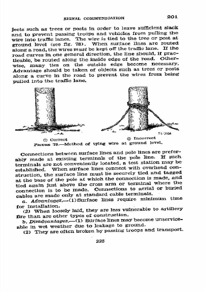
8/16/2019 (1942) FM 24-5 Signal Communication
http://slidepdf.com/reader/full/1942-fm-24-5-signal-communication 229/383
SIGNAL
COMMUNICATION
201
jects
such
as
trees
or
posts
in
order
to
leave
sufficient
slack
and
to
prevent
passing
troops
and
vehicles
from
pulling
the
wire
into
traffic
lanes.
The
wire is
tied to
the
tree
or post
at
ground
level
(see
fig.
78).
When
surface
lines
are
routed
along
a
road,
the
wires
must
be
kept
off
the
traffic
lane.
If
the
road
curves
in
one
general
direction,
the
line
should,
if
prac-
ticable,
be
routed
along
the
inside
edge
of
the
road.
Other-
wise,
many
ties
on
the
outside
edge
become
necessary.
Advantage
should
be
taken
of
objects
such
as
trees
or
posts
along
a
curve
in
the
road
to
prevent
the
wires
from
being
pulled
into
the
traffic
lane.
()
Correct
(
Incorrect
FGunRE
78.-Method
of
tying
wire
at
ground
level.
Connections
between
surface
lines
and
pole
lines
are
prefer-
ably
made
at
existing
terminals
of
the
pole
line.
If
such
terminals
are
not
conveniently
located,
a
test
station
may
be
established.
When
surface
lines
connect
with
overhead
con-
struction,
the
surface
line
must
be
securely
tied
and
tagged
at
the
base
of
the
pole
at
which
the
connection
is
made,
and
tied
again
just
above
the
cross
arm
or
terminal
where
the
connection
is
to
be
made.
Connections
to
aerial
or
buried
cables
are
made
only
at
standard
cable
terminals.
a.
Advantages.-(l)Surface
lines
require minimum time
for
installation.
(2)
When
loosely
laid,
they
are
less
vulnerable
to
artillery
fire
than
are
other
types
of
construction.
b.
Disadvantaffes.-(1)
Surface
lines
may
become
unservice-
able
in
wet
weather
due
to
leakage
to
ground.
(2)
They
are
often
broken
by
passing
troops
and
transport.
225

8/16/2019 (1942) FM 24-5 Signal Communication
http://slidepdf.com/reader/full/1942-fm-24-5-signal-communication 230/383
202 BASIC FIELD MANUAL
road~~~way~ wyUsestoieswherencessory
ko
keep
irecleorofrode .
-X~~~ TLvE~~~~-71j9A
FIGuRE 79.-Method of
tying wire along curve in
road.
*
202.
OVERHEAD CONSTRUCTION.-a.
Fleld wire lines
should
be
placed overhead
near command
posts,
test
stations, and
along
roadways
at
points
where
trafflc
is likely
to
be
diverted
from
the
roads
by
tying the
wire
to trees or existing poles 14 feet
above
the
ground
using standard
field wire
ties. At
junctions
between
overhead and
surface line
construction,
the
wires
are tied securely to the bottom
of
the support and
tagged
there (see fig. 80).
Test
stations should be installed
gen-
erally
at
the
junctions
of long overhead
lines
with other types
of constructiQn.
b.
Lance
poles
are
convenient
means
for
supporting
field
wires in overhead
construction,
particularly
where
trees,
poles, and other like.
supports are
not available.
When a
field
wire line crosses a secondary road, a guyed
lance
pole
on each
side of the road usually provides adequate
clearance
(par. 203b).
The required
18-foot road
clearance
on
main
roads
may be obtained
by
lashing two lance
poles
together.
226

8/16/2019 (1942) FM 24-5 Signal Communication
http://slidepdf.com/reader/full/1942-fm-24-5-signal-communication 231/383
SIGNAL COMMUNICATION
202-203
When
necessary, lance poles
may be supported by
lashing
them to fence
posts and
tree stumps,
and in rocky
terrain
by piling
heavy rocks
around the
bases
of
the
poles.
Field
lines of themselves often provide
sufficient guying for the
lance
pole.
An
H-frame
composed
of two
lance
poles
set
parallel to one another 3
feet
apart, with a horizontal arm
of
1-
by 2-inch lumber
fastened at
the
upper end of the
poles, provides an
excellent overhead
support for a large num-
ber of
field wires.
Guying
of the
frame
in
both
directions
perpendicularly to the
line is usually required.
Tie
Tie
/
Tag
TL-720A
FIxURE 80.-Method
of
tying
wire at
junction
of
suriace
line
withli
overhead construction.
If 203. ROAD
CROSSINGS.-a. Where
a
road
crossing
is
neces-
sary, field
wire lines should cross through a
culvert if possi-
ble. The
wires are
passed
through the
culvert,
tagged, and
tied
at
the
entrance and exit
to
prevent contact with water.
(See fig.
81.)
b.
Wires which
must
cross
roads overhead
must
clear
the
crown
of
main traffic arteries and paved roads by at least
18
feet,
and
of other
roads
by at
least
14 feet.
When
a
surface
line
crosses a
road on
poles
or other objects,
the
wire
is tied at the base and at the
top of
the object on
each
side of
the
road and tagged
at the base. The strain
which occurs along the line is
met
by the tie at
the
base.
(See
fig.
82.)
227
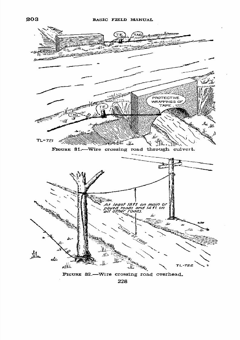
8/16/2019 (1942) FM 24-5 Signal Communication
http://slidepdf.com/reader/full/1942-fm-24-5-signal-communication 232/383
203
BASIC FIELD MANUAL
TIE
~5G
· iii[ (J, N
'
:t /eait Ift on
ra/n
or
-
_
~
i
~-PROTECTlVE
;;Cn~WRAPPlNGS
OF
T'.NJI~
~'"
11
/he r TAPEoo3
TL-721
FIGURE 81l.-W;ire crossing road through
culvert.
FIGURE 82.-Wire crossing road overhead.
228

8/16/2019 (1942) FM 24-5 Signal Communication
http://slidepdf.com/reader/full/1942-fm-24-5-signal-communication 233/383
SIGNAL
COMMUNICATION
203-204
c.
If
neither
of the
above
methods
can
be
used,
the
wires
are
buried
in a
trench
crossing
the
road
at right
angles.
The
wires
are
laid
snug,
tagged,
and
tied
to a
stake
at each
end
of
the
trench
to
prevent
their being
pulled
out.
A
suffi-
cient
amount
of
slack
wire
is left
at
one side
of
the
road
to
permit
replacement
of the
section
under
the
road,
should
it
become
worn
or water-soaked.
(See
fig.
83.)
-_
-- .-
-- ,
_S,
WIRE
BURED
TIE
E"si~iNIE
TL-723
P IGuRE
83.-Wire
crossing
under
road
in
trench.
d. Where
a
hard
surfaced
road
must be crossed
and
none
of the
above
methods
is applicable,
then
as
a last
resort,
the
wire obviously
must
be
laid
on
the
road.
Protection
of
the
wire in
this
emergency
method
is
primarily
one
of
reducing
the
risks
involved.
(1)
The smoothest
section
of
road
available
should
be
selected.
(2)
Substitute
a length
of
twisted
wire
for each
side
of
the
circuit
crossing
the road.
(3)
The
wire
should
be
laid without
slack,
tied
and
tagged
on
each side
of
the road
surface.
(4) These
parallel
crossings
should
be
separated
by more
than
the length
of the
longest
vehicle
which
will
cross.
(5) Keep
an
exact
record
of
such cases
and
inspect
frequently.
8 204.
RAILROAD
CROSSINGS.-Railroad
yards
should
be
avoided.
If
a
bridge or culvert
is
available,
it
should
be
used
229

8/16/2019 (1942) FM 24-5 Signal Communication
http://slidepdf.com/reader/full/1942-fm-24-5-signal-communication 234/383
204-206 BASIC
FIELD MANUAL
in making
the crossing
even if
tlhis requires paralleling
the
tracks
with the
wire for some
distance
in order to
reach
it.
If
a
bridge
or
culvert
is
not
available,
field
wire
lines should
cross railroad tracks
under
the rails.
(See fig. 84.) In
making
the
crossing, the
wires are pulled
tight
and buried
outside the rails
to a point beyond
the shoulders or improved
strip along the tracks, and secured on both sides to prevent
them
from
being
pulled out and
becoming
a
hazard to
train-
men walking
along
the
tracks. Field wire lines should
never cross overhead, as to do so
endangers
trainmen
on top
of
railroad
cars.
1
205.
RIVER CROSSINGS.-a.
Overhead.--Small
stream cross-
ings are made in the same manner as overhead road cross-
ings, except that
the
wires need
be
only high enough
to clear
the
water-borne traffic.
A span of more
than
150
feet should
not
bontain a splice.
Long spans up to
250
feet
can be
made
with
field wire, but
special construction is
necessary for
resisting
the strain.
b. Submerged.-When field wire lines must cross bodies of
water
such
as rivers where it
is
impracticable to make over-
head crossings, the wire
should be
submerged. The
wire is
tied
in
securely on the
near
bank, laid by paying
out from
a
reel
or
coil,
and
tied
in securely on
the far bank. The ties
are
made above the highest
level reached by
the water. The
insulation
on
the
wire should
be
sound.
Splices
should
be
made
only
if
absolutely
necessary and
should
be made as
waterproof as possible. If
the
current in
the
stream is
strong,
or
if the stream
is navigable, the wire
is
weighted
at
suitable
intervals to keep it submerged
to the full
depth
and
to
retard
its movement
by
the
current.
The amount of wire
necessary
for the crossing
is
carefully computed
and the
wire
prepared
in advance
so as to
avoid splicing the wire in
midstream.
U
206.
TRENCH LINE CONSTRUCTION.-In
position
defense, field
wire lines
are
often
installed
in trenches, two
kinds
being
generally
used-wire trenches constructed
specifically
for
that purpose, and trenches primarily
intended for other pur-
poses,
such as fire
or communication.
Trench wire lines
are
tagged
at
intervals of not more
than
150 feet and at junctions
with other
lines.
230

8/16/2019 (1942) FM 24-5 Signal Communication
http://slidepdf.com/reader/full/1942-fm-24-5-signal-communication 235/383
IGCNAL COMMUNICATION
208
4i
:li ~~~~~~~.
1/ s
231

8/16/2019 (1942) FM 24-5 Signal Communication
http://slidepdf.com/reader/full/1942-fm-24-5-signal-communication 236/383
206
BASIC
FIELD
MANUAL
a. Wire trenches (fig. 85).-(1)
Wire
trenches vary in size
from 10 inches wide
by
10 inches
deep to
36 inches wide by
30
inches
deep.
They
afford
considerable
protection from
shell fire
but offer
an
obstacle
to
friendly
traffic. The wire
may be fastened
to cross
arms
which are
attached horizon-
tally to short
poles or
rest against or project
into
the
sides
of
the
trench.
Instead of
using
cross arms the wire may be
fastened to the sides of vertical poles.
Field
wire
may be
tied
directly
to these supports with wire or marline,
but it
is
preferable
to tie
the
wire to wooden or porcelain knobs or
insulators.
(2)
The wire trench route should be chosen with a view
to
concealment, cover,
and ease of
construction. The
number
of trenches is kept to a minimum, and the wire is kept in the
main trunk-line trenches as much as practicable. Switching
centrals may
be
installed at
important trench
junctions.
f-/ed
with gr7ve/
FIGIuJEU
85.-Wire
trench
construction.
232
32
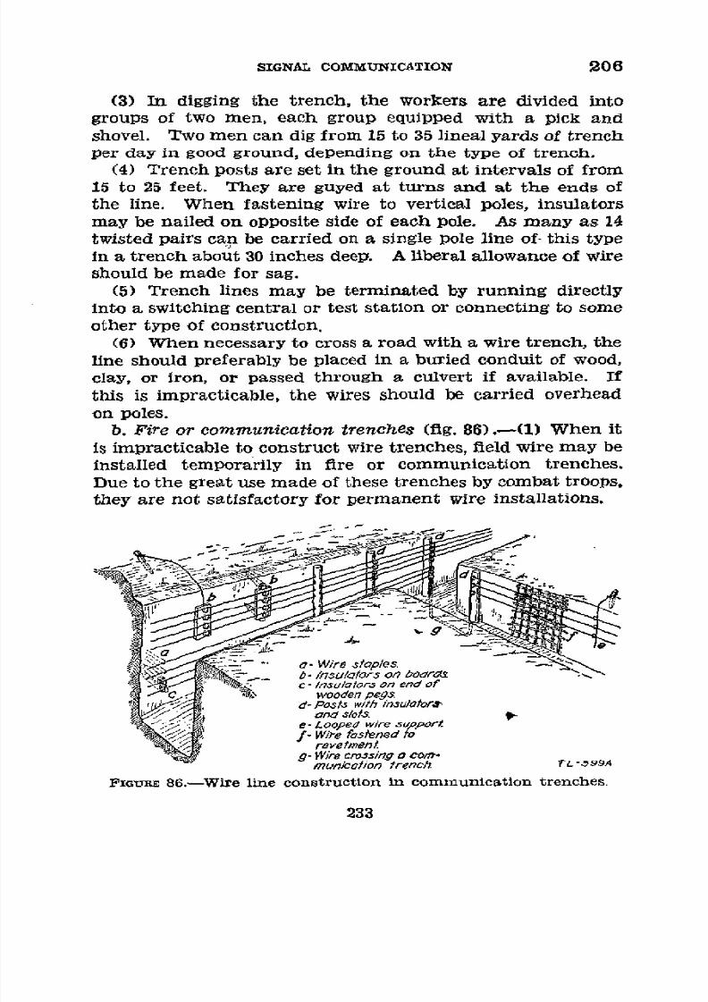
8/16/2019 (1942) FM 24-5 Signal Communication
http://slidepdf.com/reader/full/1942-fm-24-5-signal-communication 237/383
SIGNAL
COMMUNICATION
206
(3) In digging
the
trench, the workers
are divided into
groups
of two men, each
group
equipped with a
pick and
shovel.
Two
men
can
dig
from
15
to
35
lineal
yards
of
trench
per day
in good
ground,
depending
on the type
of trench.
(4)
Trench
posts
are set
in
the ground
at
intervals
of from
15
to
25
feet.
They are guyed
at turns and
at
the
ends
of
the line. When
fastening
wire to
vertical poles,
insulators
may
be nailed
on
opposite side
of
each pole.
As many
as 14
twisted
pairs
can be
carried
on
a single
pole
line
of-
this type
in a trench about
30 inches
deep. A
liberal
allowance of wire
should
be made for
sag.
(5)
Trench
lines
may
be
terminated
by
running
directly
into
a
switching
central
or
test
station
or
connecting
to some
other type
of
construction.
(6) When necessary
to cross a
road
with
a wire trench,
the
line should
preferably
be placed in
a buried conduit
of
wood,
clay, or iron,
or passed through
a culvert
if available.
If
this is
impracticable,
the
wires should
be carried
overhead
on poles.
b.
Fire
or
communication
trenches
(fig. 86).-(1)
When
it
is impracticable
to
construct
wire
trenches,
field
wire may
be
installed
temporarily
in fire
or communication
trenches.
Due
to
the great
use made
of these trenches
by combat
troops,
they
are not satisfactory for
permanent
wire installations.
£- W'/re
stap7es
/1nsu/oorso0/7 oors
c-/nsu/ators
on
end
of
wooden
pegs
d-Postk with
inSulotor.
t/i
aond s/ots
e- £ooped
wire zupper
fo W/i-e
ast5ned to
revetmenL
-
W/re
crossing
o om*
munaí/ion
trench
TL->99A
PxGURE
86.-W ire line
construction
in
communication
trenches.
233
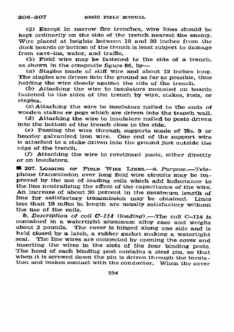
8/16/2019 (1942) FM 24-5 Signal Communication
http://slidepdf.com/reader/full/1942-fm-24-5-signal-communication 238/383
206-207
BASIC
FIELD
MANUAL
(2)
Except
in
narrow
fire
trenches,
wire
lines
should
be
kept
ordinarily
on
the
Side
of
the
trench
nearest
the
enemy.
Wire
placed
at
heights
between
10
and
30
inches
from
the
duck
boards
or
bottom
of
the
trench
is least
subject to
damage
from
cave-ins,
water,
and
trafflc.
(3)
Field
wire
may
be fastened
to the
side
of
a
trench,
as
shown
in
the composite
figure
86,
by-
(a)
Staples
made
of
stiff
wire
and
about
12
inches
long.
The
staples
are driven
into
the
ground
as
far as
possible,
thus
holding
the
wire
closely
against
the
side
of the
trench.
(b)
Attaching the
wire
to insulators
mounted
on
boards
fastened
to the
sides
of the
trench
by
wire,
stakes,
rods,
or
staples.
(c)Attaching
the
wire
to
insulators
nailed
to
the
ends
of
wooden
stakes
or
pegs
which
are
driven
into
the
trench
wall.
(d)
Attaching
the
wire
to insulators
nailed
to
posts
driven
into
the
bottom
of the trench
close
to the
side.
(e)
Passing
the
wire
through
supports made
of
No.
9
or
heavier
galvanized
iron
wire.
One
end
of the
support
wire
is attached
to
a
stake
driven
into
the
ground
just outside
the
edge of
the
trench.
(f) Attaching
the
wire
to
revetment
posts,
either
directly
or
on
insulators.
*
207.
LOADING
OF
FIELD
WIRE
LNES.---.
Purpose.-Tele-
phone
transmission
over
long
field
wire
circuits
may
be
im-
proved
by
the
use
of
loading
coils
which
add
inductance
to
the
line
neutralizing
the
effect
of the
capacitance
of
the
wire.
An
increase
of
about
30
percent
in
the
maximum
length
of
line
for
satisfactory
transmission
may
be
obtained.
Lines
less
than
10
miles
in
length
are
usually
satisfactory
without
the
Use
of the coils.
b.
Description
of
coil
C-114
(loading)
-
The
coil
C-114
is
contained
in a
watertight
aluminum
alloy case
and
weighs
about
2 pounds.
The
cover
is
hinged
along
one
side
and
is
held
closed
by
a
latch,
a
rubber
gasket
making
a
watertight
seal.
The
line
wires are
connected
by
opening
the
cover
and
inserting
the
wires
in the
slots
of
the
four
binding
posts.
The
head
of
each
binding
post
contains
a
steel
pin,
so
that
when
it
is
screwed
down
the
pin
is
driven
through
the
insula-
tion
and
makes contact
with
the
conductor. When
the
cover
234
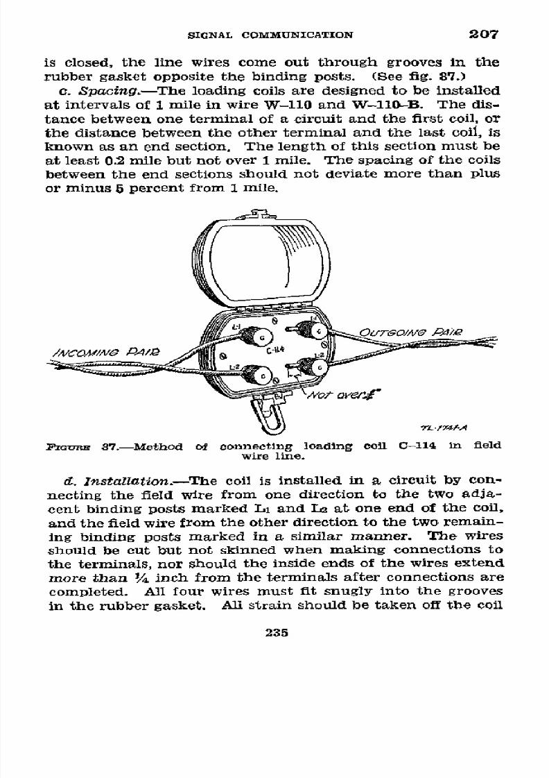
8/16/2019 (1942) FM 24-5 Signal Communication
http://slidepdf.com/reader/full/1942-fm-24-5-signal-communication 239/383
SIGNAL
COMMUNICATION
207
is
closed,
the
line wires
come
out through
grooves
in the
rubber gasket
opposite
the binding
posts.
(See fig. 87.)
c. Spacing.-The
loading
coils
are
designed
to
be
installed
at
intervals
of 1
mile
in
wire
W-110
and
W-l10-B.
The
dis-
tance
between
one
terminal
of
a
circuit
and
the
first coil,
or
the
distance
between
the
other
terminal
and the
last
coil, is
known
as an
end section.
The length
of
this
section
must
be
at
least
0.2 mile
but not over
1 mile.
The
spacing
of
the coils
between
the end sections
should
not deviate
more
than
plus
or
minus
5 percent from
1
mile.
//V/COM/X/Vt
Ed
Q
/
íN4
.2
-
CO0M/NPAI
s
/741
-
FGaUr
87.-Method
of
connecting
loading
coil
0-114
in
field
wire
line.
d. Installation.-The
coil
is installed
in
a
circuit
by con-
necting
the
field
wire
from
one
direction
to
the
two
adia-
cent
binding
posts
marked
Li and
La at
one
end
of
the
coil,
and
the field
wire
from
the other
direction
to the
two
remain-
ing
binding
posts
marked
in
a
similar
manner.
The
wires
should
be cut
but
not skinned
when
making
connections
to
the terminals,
nor
should
the
inside
ends
of
the
wires
extend
more
than
1/4
inch
from
the
terminals
after
connections
are
completed.
All four
wires must
fit
snugly
into the
grooves
in
the
rubber
gasket.
All
strain
should
be
taken
off
the
coil
235

8/16/2019 (1942) FM 24-5 Signal Communication
http://slidepdf.com/reader/full/1942-fm-24-5-signal-communication 240/383
207-208
BASIC
FIELD MANUAL
connections in order to avoid damage to
the
coil and
reduc-
tion in
the tensile
strength of the line.
*
208. EXPEDIENTS.---a. Many units have
found
that at higher
headquarters some
central
point,
other than the
switchboard,
is
an advantageous
one
from which to control wire crews in
action and make
tests
on
trunks
or
long locals.
Such an
installation
removes
these
duties
from
switchboard
personnel,
thus
increasing
their efficiency.
It could be located
at
the
edge of
the
command
post
where
all the
long
lines
from
the
front are arranged to come together
upon
entering
the
com-
mand
post
area.
It
is
called
a
"construction center."
The
size
and amount
of equipment
thereat
may
vary widely
from
a
terminal
strip and
telephone with test leads
to the inclusion
of a
test switchboard
and test set.
However,
if
such
a center
is established,
only available
standard
equipment should
be
used and so
installed
as to
be
readily removed or dissembled.
Figure
88
shows
one
such construction
center temporarily in-
stalled in a trailer.
Figure 89 is a
suggested
circuit
diagram
for
such
an
installation
which
might
be
found
at
a
division
headquarters.
The
equipment
is,
by improvisation,
installed
on
one
side of
the
trailer and is operated by an
enlisted
con-
struction chief.
The
diagram shows all
incoming trunks and
long
locaIs
terminating at a terminal
strip. From this
strip
the circuits
when completed
and serviceable are
taken
directly
through another terminal strip to the switchboard.
By the
use
of
test
clips,
jumper
wires,
or
improvised
switches
the cir-
cuit
may,
instead of going direct
to the switchboard, be
switched
to
a
test telephone
switchboard
affording
a
lineman
or construction
crew
working
on
the
line
an opportunity
to
call
the
construction
chief
for a test, additional
instructions,
or
to
report
his
progress.
The
switchboard
gives
the
construction
chief, by the use
of his operator's phone
or set, access to any
of
his
long
lines. If desired,
the test
set leads
may
be
equipped
with a spare switchboard
plug.
Thus
he
may
quickly
connect
his test set
to
any line by
the
insertion of the
test
set
plug
into the switchboard jack to
which
such line is connected.
The trailer shown
in
figure 88
may
normally be
used
to trans-
port communication
equipment.
b. It has been
found
that laying
field wire from a
truck
can
be
accelerated
by the
use of an
improvised,
laterally
and
236
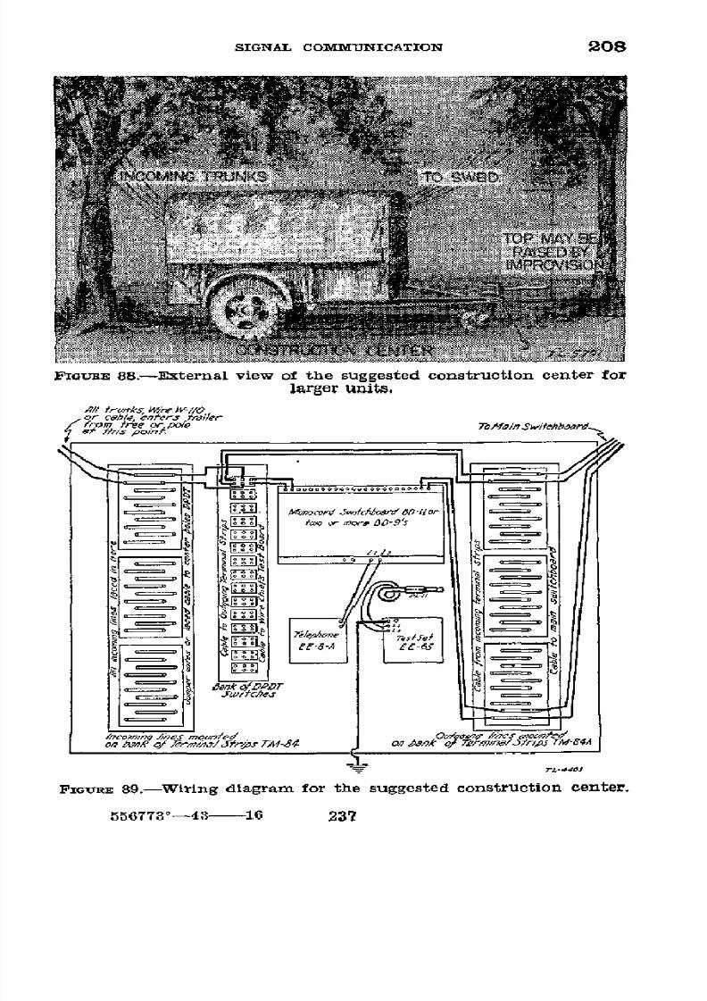
8/16/2019 (1942) FM 24-5 Signal Communication
http://slidepdf.com/reader/full/1942-fm-24-5-signal-communication 241/383
SIGNAL
COMMUNICATION
208
F;IGtUE
88.-External
view
of
the
suggested
construction
center
for
larger
units.
h//
r',
ks,
Wes
v//O
or cabe
ner
rer
i fromf~ee po/e Te/frl rnitchboora
e7h.e
o/,,
.nkO/.oDo
r
J
erv
fr......
D-..
or
E--_l
I
J
0_=_
FIGuRE
89.-W lring
dlagram
for the
suggested
construction
center.
556773'---4
16
237

8/16/2019 (1942) FM 24-5 Signal Communication
http://slidepdf.com/reader/full/1942-fm-24-5-signal-communication 242/383
208 BASIC FIELD MANUAL
vertically adjustable, wire
boom.
Its
efficiency
is greatly de-
pendent
upon a trained
crew
as, at first, the speed
and
dis-
tribution of slack attained is
likely
to be
discouraging.
This
boom,
attached
to
a
truck
in
which
a
reel
unit
RL26
or
RL-31 has been mounted, is so equipped as to lay two circuits
simultaneously
and at such a
horizontal
angle that the
wire
falls well
off
the
road. This
initially
affords
protection of the
wire from
traffic
but does
not
eliminate the
necessity for
sub-
sequently inspecting and servicing the
completed line
for
slack, ties, tags, and additional circuit protection.
Overhead
crossings,
tying,
underground
crossings,
and
occasional
ac-
cumulations
of
slack may be secured by
leaving
behind one
or
more
linemen and sufficient
slack wire
to
perform
the mis-
sion. As circuit establishment speed is paramount, this causes
the wire
layer minimum
delay. A
tender
vehicle,
such
as
'/
4
-ton
truck, following the wire layer
would
pick up the
line-
man
left behind and
quickly shuttle
him forward to
rejoin
the wire layer. The lateral position
of
the wire boom is
adjusted
by
one guy
line
and
the
vertical
by
another.
Two
men on the alert in the wire layer operate the
guy
lines
to
prevent the boom
from
striking obstacles passed such as trees,
posts, and heavy brush. When
not
so
engaged
they assist
the reelman. One suggested plan
of
boom construction is
illustrated in figure 90.
Other
types
or improvements may
be
suggested by
use and experience. In operation,
the
wires
from
the
reel
drums
are
threaded through the
sheaves shown
and
after
the reel wire
drums
and truck attain
momentum
the
wire feeds
out.
Additional slack is attained by
mo-
mentarily decreasing the truck speed
but
permitting the reel
drums to
run freely. When the truck stops,
the reel
drum
brake must be applied by the reelman.
It
is suggested the
truck speed be
controlled
by telephone or by the reelman
blowing whistle blasts such
as-
One
blast-stop
Two
blasts-go
or faster if
underway
Three blasts-slower
speed
Wire has
been
satisfactorily
laid with
this boom at an all
inclusive rate of
from 8
to 14
miles
per
hour.
c.
The use
of such expedients to increase efficiency by
238

8/16/2019 (1942) FM 24-5 Signal Communication
http://slidepdf.com/reader/full/1942-fm-24-5-signal-communication 243/383
SIGNAL COMMUNICATION
208-209
> j
z
f
7
9O
0o
o
we
FIGURE 90o.-One
suggested
form of wlre
boom.
permitting earlier
establishment
of
communication
is en-
couraged but
is
not
directed
and
should
not
be taken
as
a basis
of
converting
transportation
solely to
this
use.
SECTION III
FIELD
TELEPHONES AND CENTRALS
*
209.
INSTALLATION
OF SWITCHING
CENTRALS.---.
Installation
of a
feld switching
central includes
installing
the
switch-
board
and
its
auxiliary
equipment,
terminal
strips
if required,
and testing equipment
if available.
It
also
includes
the
in-
stallation
of local
circuits
and
telephones
(except long
locals),
and
making
the
proper
connections
at
the
switchboard
terminal strip
between these circuits
and
the
trunk
circuits
turned over by
construction
details.
b. Each
circuit
is
tested
as soon
as it
is connected,
and
when it
is in satisfactory
operative condition
the
time
is
recorded and
the
message
center is informed
of
the avail-
able service.
A traffic
diagram
(see
par.
223) is
prepared
239

8/16/2019 (1942) FM 24-5 Signal Communication
http://slidepdf.com/reader/full/1942-fm-24-5-signal-communication 244/383
209--10
BASIC
FIELD
MANUAL
and
posted
at
the
switchboard
together
with
a copy
of
the
telephone
directory
for
the
use
of
the
operator.
c.
Trunk
circuits
available before
they
can
be
connected
to
the switchboard,
are
connected
directly
to
telephones
to
give
temporary
service
until
the
switchboard
is installed.
d. After
the switching
central
is
installed
and
operating,
circuits
should
be rearranged
for
their
better
protection
and
to facilitate
maintenance.
Care
is
taken
that
circuits
radi-
ating
from
a
switching
central
are
not
subject
to interfer-
ence
from
troops
and
traffic
in the
vicinity
of
the
command
post. They
are
placed overhead
or underground.
e.
Priority
in
which
local
telephones
are installed
at
a
command
post
varies
with
the situation
and
the orders
of
the
commander.
They
are
normally
installed
in the
fol-
lowing
order:
(1)
Message center.
(2)
Commander
(or chief
of
staff
or executive).
(3)
Operations
section
(G-3
or
S-3).
(4)
Intelligence
section
(C-2
or
S-2).
(5) Supply
section
(G-4
or
S-4).
(6)
Signal
section
(signal
officer).
(7) Personnel
section
(G-1
or
S-1).
(8)
Public
telephone
for personnel
not
furnished
individ-
ual
telephones.
(Installed
convenient
to
staff
personnel
and
well
marked
as the
public
telephone.)
(9)
Other
staff
officers
and
activities
as
required.
f.
At
command
posts
of
small
units,
as in
battalions
or
regiments,
one
telephone
ordinarily
serves
two
or more
staff
officers.
At
larger
headquarters,
more
than
one
telephone
may
be
required
in each
staff
section.
At
all
echelons,
tele-
phones
are
reduced
to
minimum
requirements.
* 210.
INSTALLATION
OF TELEPHONE
SWITCHBOARDS.-A
field
switching
central may
include
one
or
more
switchboards,
de-
pending
on the
number
of trunk
and local
circuits
to
be
installed.
With certain
types
of
switchboards
it
is necessary
to
install
terminal
strips;
with
others,
the
terminal
strips
and
repeating
coils are
self-contained
in
the
switchboard
itself.
The
switchboard
and
its
associated
equipment
are in-
stalled
in
a
centrally
located
place
affording
as much
shelter
240
8/16/2019 (1942) FM 24-5 Signal Communication
http://slidepdf.com/reader/full/1942-fm-24-5-signal-communication 245/383
8/16/2019 (1942) FM 24-5 Signal Communication
http://slidepdf.com/reader/full/1942-fm-24-5-signal-communication 246/383
212-214
BASIC FIELD MANUAL
When an
installation has been
tested
and is completed, the
user is
immediately
informed of
that
fact.
5
213.
TYPES
OF
FrELD
TELEPHoNES.-The
field
type tele-
phones
in common
use
are
the EE-8-A,
EE-8, EE-5, and
EE-3B. These instruments have common operating charac-
teristics but
vary in details
of construction. (See par.
2,
app.
I, for descriptions.)
U
214.
TESTING
FIELD
TELEPHONES.-A
field telephone
must
perform two distinct functions: Signaling of the
distant
and
local
party, and
transmission and
reception
of
speech.
Separate apparatus
and
circuits
are provided
for both
functions, properly interconnected
to
the single pair of
field wires. The simplest and most comprehensive
field
test
of a telephone is
to connect
an instrument
known to
be satis-
factory
to
the
telephone
under test by
means
of
a
short line.
If both
telephones
can be signaled
satisfactorily,
and
if speech
can be
transmitted intelligibly
without effort, the
telephone
under
test
is in an operative condition. If the telephone
is
not serviceable,
or
if more
specific
tests as
described
below fail,
the
telephone should
be
turned in
for
repair.
a. Test of signaling circuits.-The magneto or hand-
operated generator furnishes
signaling
currents for the
tele-
phone.
It should
turn
freely
when not connected
to
a line.
Short-circuiting
the line binding
posts should produce a defi-
nite
drag
on
the
crank.
The
internal
ringer
or
buzzer
is
tested by
connecting
the
telephone to another serviceable
telephone
and cranking
the generator
of
the
latter. The
ringer or
buzzer
of
the
field telephone
under
test
should
respond
energetically.
b.
Test
of
speech
circuits.-Field-type elephones require
a
suitable battery for speech transmission when used on local
or
common
battery systems (sound-powered
telephones
are
exceptions).
Brighten
the
spring
or
clip
terminals in
the
battery
compartment
if inspection
discloses they are
cor-
roded.
Place
a
new dry-cell battery of
proper type
in the
compartment. Blowing into
the transmitter
of
telephones
EE-8-A
and EE-8
should produce an audible sound
(side-
tone)
in the
receiver
when the handset button or
switch
is
operated.
In
the
telephones EE-5 and
EE-3B, short-circuit
242
8/16/2019 (1942) FM 24-5 Signal Communication
http://slidepdf.com/reader/full/1942-fm-24-5-signal-communication 247/383
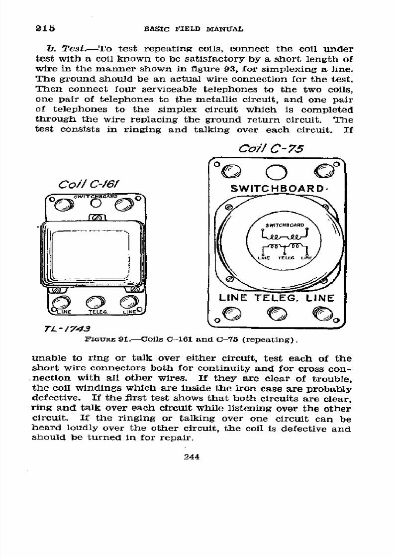
8/16/2019 (1942) FM 24-5 Signal Communication
http://slidepdf.com/reader/full/1942-fm-24-5-signal-communication 248/383
215
BASTC
FIELD
MANUAL
b.
Test.-To
test
repeating
coils,
connect
the
coil
under
test
with
a coil
known
to
be satisfactory
by
a short
length
of
wire
in the
manner
shown
in figure
93,
for
simplexing
a
line.
The ground
should
be
an actual
wire
connection
for
the
test.
Then
connect
four serviceable
telephones
to
the
two
coils,
one
pair
of telephones
to
the
metallic
circuit, and
one
pair
of telephones
to
the
simplex
circuit
which
is
completed
through
the
wire
replacing
the
ground
return
circuit.
The
test
consists
in
ringing
and
talking
over
each
circuit.
If
Coi/l
C-
75
Coi/
C-61
SWITCHBOARD
-
O
-
1
4C
/
3GURE
91.
-161
and
-75
(repeating).
FIGURE
91.-Ools
161
and C 7 5
(repeating).
unable
to ring
or talk over
either
circuit,
test
each
of
the
short
wire
connectors
both
for
continuity
and
for
cross
con-
nection
with
all
other
wires.
If
they
are
clear
of
trouble,
the
coil
windings
which
are
inside
the
iron
case
are
probably
defective.
If the
first
test
shows
that
both
circuits
are
clear,
ring
and
talk over
each
circuit
while
listening over
the
other
circuit.
If the
ringing
or
talking
over
one
circuit
can
be
heard
loudly
over
the
other
circuit, the
coil
is defective
and
should be
turned
in
for repair.
244
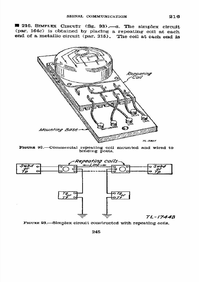
8/16/2019 (1942) FM 24-5 Signal Communication
http://slidepdf.com/reader/full/1942-fm-24-5-signal-communication 249/383
SIGNAL
COMMUNICATION
216
*
216.
SIMPLEX
CIRCUIT
(fig.
93).-a.
The
simplex
circuit
(par.
164c)
is obtained
by
placing
a repeating
coil
at
each
end
of
a
metallic
circuit
(par.
215).
The
coil at
each
end
is
nGURE
92.-Commercial
repeating
coil
mounted
and wired
to
binding
posts.
.-CReeai0ty
co/is
T
-
744B
FIGURE
93.-Simplex
circuit constructed with repeating
coils.
245
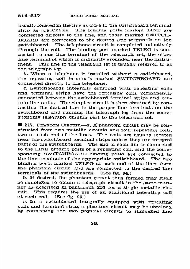
8/16/2019 (1942) FM 24-5 Signal Communication
http://slidepdf.com/reader/full/1942-fm-24-5-signal-communication 250/383
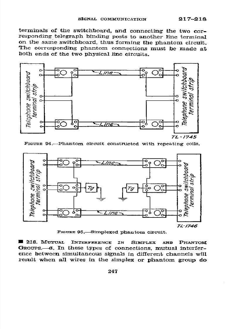
8/16/2019 (1942) FM 24-5 Signal Communication
http://slidepdf.com/reader/full/1942-fm-24-5-signal-communication 251/383
SIGNAL
COMMUNICATION
217-218
terminals of the
switchboard,
and
connecting the two cor-
responding
telegraph
binding
posts
to
another
line
terminal
on
the
same
switchboard,
thus
forming
the
phantom
circuit.
The corresponding phantom connections
must be
made
at
both
ends of the
two physical
line
circuits.
TZL
1745
FPGURE
94.-Phantom
circuit constructed
with repeating coils.
)s s'
O
IO
TL-/746
FzIGRE
95.Simplexed
phantom
circuit.
* 218.
MITUAL
INTERFERENCE IN
SIMPLEX AND PHANTOM
GROUPS.--a. In these types
of
connections,
mutual interfer-
ence
between
simultaneous
signals
in different channels
will
result
when
all
wires in the simplex
or phantom
group
do
247

8/16/2019 (1942) FM 24-5 Signal Communication
http://slidepdf.com/reader/full/1942-fm-24-5-signal-communication 252/383
218-220
BASIC FIELD MANUAL
not have
exactly the same
impedance.
The circuits are
then
said to be
unbalanced and the amount
of
the
interference
will
depend
upon
the
degree
of
unbalance
between
the
two
physi-
cal,
or metallic,
circuits.
The
primary causes are
poor splices
which
introduce a high
resistance
into either side of the
circuit
and
improperly taped splices or damaged insulation
which, particularly
when
wet,
result
in excessive leakage
from
one
side
of the
circuit
to
ground. Although
it
is impossible
to obtain
a
perfect
impedance
balance
in field
wire
circuits,
mutual
interference may
be
reduced
to a
negligible
value by
making
sure
that
each
wire
of
a
group
is of
approximately
the
same length
and
that all splices
are well
made,
and
by
employing
overhead construction at low,
wet
places
and
dur-
ing rainy
weather.
Resistance
unbalance may
be
corrected
and
mutual
interference
reduced
to
a
minimum by
inserting
and
adjusting
a variable
resistance
in
the
low
resistance
side
of an unbalanced circuit. The
low resistance side is deter-
mined
by trial.
b.
The
interference
resulting from any unbalance
is
usually
more
pronounced in
a phantom group
than
in
a simplex
circuit
as
there are
more circuits
involved
in
the
former.
Furthermore,
due
to
their similarity of sound,
interference
between
telephone
channels is
much
more
serious
than
the
interference
from
telegraph key clicks.
Ordinarily,
a
phan-
tom circuit should be
used
in feld
wire
systems
only when
the
phantom
circuit can
be
immediately
removed,
in
case
of
undesirable crosstalk, without
eliminating
an
essential
talk-
ing
channel. The
use
of simplex
circuits
usually
is confined
to
the
superposition
of
telegraph
facilities
on the wire
systems.
* 219.
TYPES OF FIELD
SWITCHBOARDS.-The
switchboards
in
common
use on
field wire systems
are the
BD-72, BD-71,
BD-11,
BD-9,
and
telephone central
office
sets
TC-4
and
TC-12. Except
for
the TC-4,
these
are all
monocord
switch-
boards, and
are described
in paragraph
3, appendix L
h 220.
SWITCHBOARD
OPERATOR.-The
ideal switchboard
oper-
ator
is
courteous,
intelligent,
efficient,
and
capable of
working
for
prolonged periods under
stress.
He
should
be familiar
with
Army organization,
should
be
able
to speak
distinctly,
248

8/16/2019 (1942) FM 24-5 Signal Communication
http://slidepdf.com/reader/full/1942-fm-24-5-signal-communication 253/383
SIGNAL
COMMUNICATION
220-221
and
should
be
able
to
understand
speech
over
the
telephone
readily.
U
221.
OPERATING
PHRASES.-The
following
phrases are
pre-
scribed
for
use
by switchboard
operators
in
all cases
where
they
apply,
to
the exclusion
of
other
phrases of
similar
meaning:
a. "Magic
operator."
Used
by the
operator
in
answering
a
call
at the
switchboard
of
the
unit
whose
directory
name
is
Magic.
b.
"Magic
-.
"
(Blank
is
appropriate
directory
number.)
Used by
an
operator to indicate
that
he
has
correctly
under-
stood
a number
given
to him
by
either
a local
party
or by
an
operator
of
another
central,
and
that
he
is
proceeding
to
complete
the call.
c.
"What
number
please?"
Used
by an
operator
to
request
repetition
of a number
which
he
has not
understood.
d.
"The
line
is
busy."
Used
by
an
operator
to
report that
a
local
telephone for
which
he
has
received
a
call
is
already
in use.
e.
"Maytime
is
busy."
Used
by
an
operator
who
has
re-
ceived
a
call
to
be completed
to
a certain
central
(Maytime)
to
report that all
trunks
to
that
central
are
in
use.
f.
"Magic
three-three
does
not
answer."
Used
by
an
oper-
ator
in
reporting
that
a
called
party
(Magic
three-three)
does
not
answer.
g.
"Maytime
does
not
answer." Used
by
an
operator
in
reporting
that
a
certain
called
central
(Maytime)
does
not
answer.
h.
"Here's
your
party."
Used
by
an
operator
whenever
it
is necessary
for
him
to
start
the
conversation
over
a
con-
nection.
i. "Are
you
through?"
Used
by
an
operator
in
supervising
a
connection,
when
no
conversation
is
heard.
Repeat
the
challenge
at
least
once
if
no
reply is
heard.
j.
"I will
ring again."
Used
by
an
operator
when,
in
super-
vising
a connection,
he
is
informed
that the
called
party
did
not answer.
k.
"What
number
is
calling,
please?"
Used
by
an operator
if,
after
supervising
a connection,
he
is
given
a new
number
249
8/16/2019 (1942) FM 24-5 Signal Communication
http://slidepdf.com/reader/full/1942-fm-24-5-signal-communication 254/383
221-222
BASIC FIELD
MANUAL
to
call
by one
of the
parties
and
he
is otherwise
unable
to
identify
that party.
1.
"Magic
three-zero
has
no
telephone
but
I can give
you
Magic
one-one."
Used
by
an
operator
when
there
is
no tele-
phone
at the
number
called,
but another
telephone
is available
to which
the
calling
party
might
desire
to
be connected.
m.
"What
number
were
you
calling,
please?"
Used
by an
operator
to
determine
the
number
desired
by
a
party
who
reports
he has been
given
a wrong
number
or
has
been
cut
off.
n. "One
moment
please"
or
"I
have
a
call for
you."
Used
by
an
operator if
necessary,
to hold
either
party
on
the
line
while a
connection
is being
completed.
o.
"Calling
Magic," or
"Calling Magic
one-one."
Used by
an
operator
when
there
is
confusion
or
interruption
in getting
an operator
or called
party
on
the
line.
p. "I
must interrupt-urgent
call
from
Magic six-please
hang up."
Used by
an
operator
to inform the
parties
using
a circuit
that
it
is required for
an urgent
call by
a certain
calling
party.
*
222.
SUPERVISION.-a.
A
switchboard
operator
supervises
each connection
to
insure
that
conversation
is established
between
the
calling
party
and
the
called
party,
and
to
remove
the connection
as soon as
possible
after the
conversation
is
completed.
The
operator
listens
in after
he
has made
a con-
nection
and rung
the
called party, waiting
to
hear
the
called
party
answer
and
conversation
begin.
He
remains
in
on
the
connection
of
a
trunk call
to another central
until the
other
central
has
answered
and he
has passed
the call to
the other
central.
If it
be
necessary
to answer
another
call
before
he
has
supervised
a connection,
he does
so at the
first opportunity.
A
shutter is
never
restored
on a connection
until
it has been
supervised.
b. In
supervising
a connection which
has already been
established, no conversation
is
heard,
he
challenges
by
asking
"Are
you through?"
Great
care
is taken
not
to
interrupt
a
conversation
in
progress.
If after a
second challenge,
he
receives
no
response,
he
takes
down
the connection.
If
he
is
notified
that
the called
party
has
not
answered,
he answers,
"I will ring
again,"
and does
so. If
he
is informed
that
the
250

8/16/2019 (1942) FM 24-5 Signal Communication
http://slidepdf.com/reader/full/1942-fm-24-5-signal-communication 255/383
SIGNAL
COMMUNICATION
222-225
connection
is
still in
use,
he
removes
his
operator's
plug.
Connections
are supervised frequently
in
the
above
manner
in case both parties may have failed to ring off
when
the
conversation
was completed.
c. Normally, when
a conversation
is completed,
the shutter
on
the
connection will
fall
due to
one
of
the
parties ringing
off. This
is the
signal
for the operator
to
supervise
the
con-
nection
in
the same manner as
in
b above. If a new number
is given him by either
party he asks, "What number is call-
ing?"
and proceeds
to complete the
call
in
the
usual manner.
U
223.
TELEPHONE
TRAFFIC
DIAGRAM.-a.
A
traffic
diagram
is
a
chart
showing
the
number
of telephone channels
actually
existing
between
the switching centrals
of a
telephone
system.
Circuits
connecting
distant
locals
are
also
shown. A single
line
indicates
direct telephone communication;
a numeral
placed
on
the line
indicates
the number of
channels available
including phantom
circuits.
The
units
to which
each switch-
ing
central
or
distant
local
pertains
are indicated
by
the
tele-
phone directory
name
or otherwise.
b. The telephone traffic
diagram
is prepared
at
each switch-
board by
the
wire
chief or
chief
operator,
assisted by
the
operator
on duty,
from
information received
over
the wire
system
and shows
such circuits
only as
are available for
traffic. Its purpose
is
to indicate to
the
operatoc
the
most
direct
routing for a call to
any
other central in the
system
and
to
show
alternate
routings
in
case
the
direct routing
is
busy
or
out
of order. For this purpose
it often includes
connecting
telephone
systems
of
other higher,
lower,
and
adjacent
units.
It must be
corrected
continuously as
changes
occur and
expanded as
information
is
obtained.
An
example
of a
telephone
trafflc
diagram
is shown in figure
105.
h 224. RECORDs.-At
each switching central such records
cov-
ering
its
operation are kept
as
required
by
the
signal
or
communication officer.
These records may include
a station
log and a
test
and
trouble
record (pars.
225 and
235).
*
225.
STATION
LOG.-The station log is kept by the switch-
board operator on
duty under
the supervision of
the chief
251
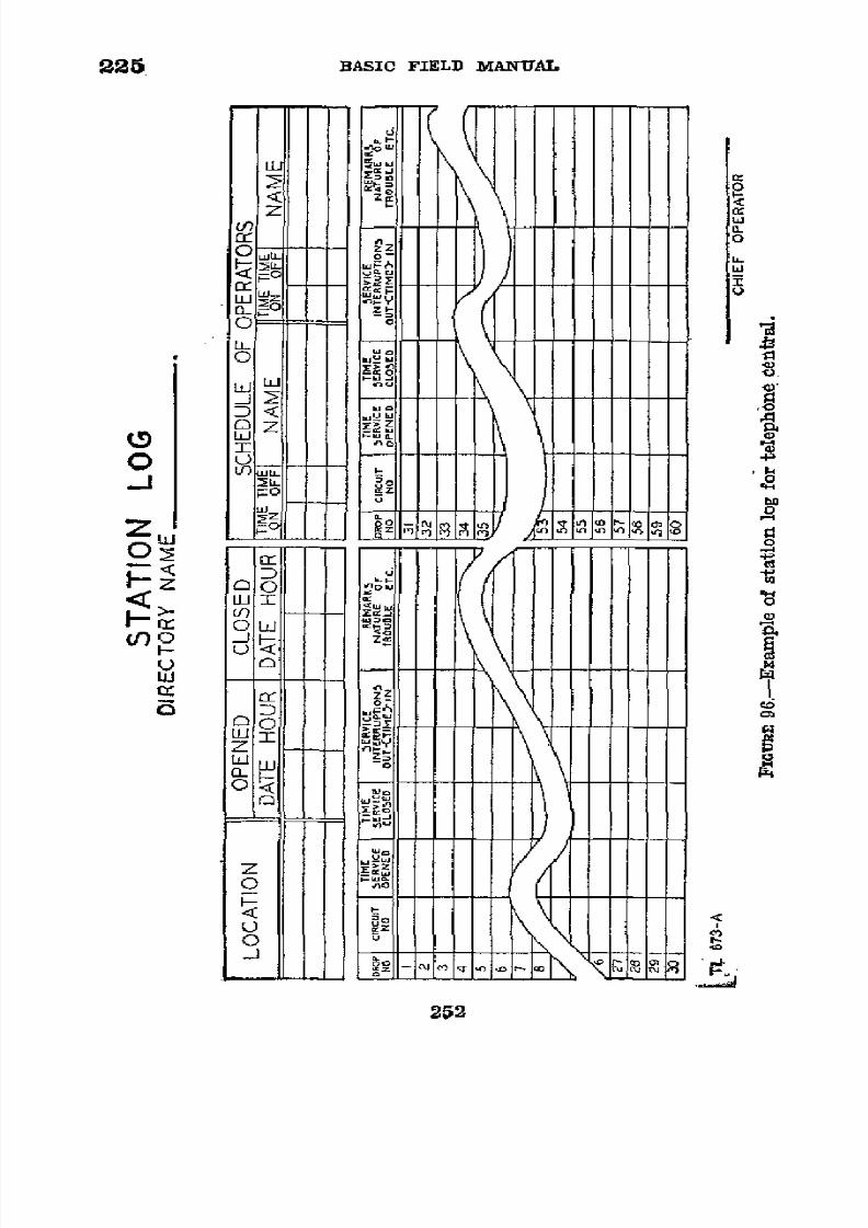
8/16/2019 (1942) FM 24-5 Signal Communication
http://slidepdf.com/reader/full/1942-fm-24-5-signal-communication 256/383
225
BASIC
FIELD
MANUAL
;Q
o
a~~~~~~~~~~
rr
0
C)
z'
M
IC
-
-
-
-
-
-
-
-
-
-
-
-
m
u
Z,
·
s2
On
U
o~~~~~~~~~~~~~~~~~~~~h
ry
D
Z'~~~Z
Li
II"9
II
III
h4I
I
cc'z
0:
1,
1
1
I
I
I
\
\
LLI( ((((I \
( I
252
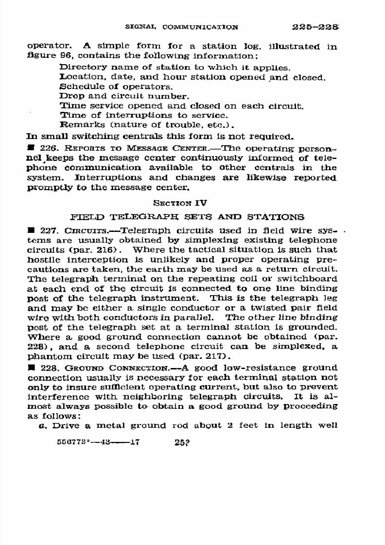
8/16/2019 (1942) FM 24-5 Signal Communication
http://slidepdf.com/reader/full/1942-fm-24-5-signal-communication 257/383
SIGNAL
COMMUNICATION 225-228
operator.
A simple
form for
a station
log,
illustrated in
figure 96, contains the following information:
Directory
name
of station
to which it applies.
Location,
date,
and hour
station
opened
and
closed.
Schedule of
operators.
Drop
and
circuit number.
Time service opened and closed on
each
circuit.
Time
of
interruptions to
service.
Remarks
(nature of trouble,
etc.).
In small switching
centrals
this form is not required.
U
226.
REPORTS
TO
MESSAGE
CENTER.-The
operating
person-
nelkeeps the message
center continuously
informed of tele-
phone communication
available to other centrals in the
system.
Interruptions and
changes are likewise
reported
promptly
to
the message center.
SECTION
IV
FIELD TELEGRAPH SETS AND STATIONS
U 227.
CIRcuTS.-Telegraph
circuits
used in
field
wire
sys-
tems
are usually
obtained
by simplexing existing
telephone
circuits (par. 216).
Where
the tactical
situation
is such
that
hostile interception is
unlikely and
proper operating pre-
cautions are taken, the earth may
be used
as a return circuit.
The
telegraph terminal on the repeating
coil or switchboard
at each end
of the circuit
is
connected to one
line binding
post of
the telegraph instrument.
This
is
the
telegraph
leg
and may be either a single
conductor
or
a twisted
pair field
wire
with
both
conductors in parallel.
The other
line binding
post of
the telegraph
set
at
a
terminal station is grounded.
Where a good
ground
connection cannot be
obtained (par.
228), and a second
telephone
circuit
can
be simplexed, a
phantom
circuit may
be used
(par. 217).
·
228.
GROUND
CONNECTION.-A
good
low-resistance ground
connection usually
is
necessary for each terminal
station
not
only to insure sufficient
operating
current, but also
to
prevent
interference with neighboring telegraph
circuits.
It is al-
most
always
possible to obtain a good
ground
by
proceeding
as
follows:
a. Drive a
metal ground
rod
about
2
feet in
length well
556773'-43-17
25?

8/16/2019 (1942) FM 24-5 Signal Communication
http://slidepdf.com/reader/full/1942-fm-24-5-signal-communication 258/383
228-231
BASIC FIELD MANUAL
into the
ground where it is moist.
Use a longer rod
if
one
is necessary
and
available.
Usually
the ground near
the
roots
of a
shrub, cactus, or other
vegetation is
moist.
The
ground'
rod, or a
long
spike,
may
be
driven
into the
roots
proper.
If
only dry ground is
available, wet it thoroughly
and
pack
it down
around
the
rod.
b. Use a separate
ground for each telegraph
set
or
other
equipment and keep separate
grounds at least 15
feet apart.
c. Use two or more ground rods at least 15 feet
apart
con-
nected together
for a single
set
if one
ground rod will
not
suffice.
d.
Keep
the
wire leading from
the
ground
rod to
the
set
reasonably short,
but do
not
hesitate
to use
a wire several
hundred
yards long
if
necessary
to reach moist ground,
such
as a
stream
bed.
U
229. BRIDGING
SIMPLEXED
CIRCTITS
AROUND A SWITCHBOARD.-
When a
telephone circuit which
is
to be simplexed for tele-
graph
passes
through
an
intermediate
telephone
central
at
which
no
telegraph
set is
to be
located
it
is
necessary
to
make the
simplex circuit continuous
by bridging it
around
the telephone
switchboard
by means
of repeating coils (par.
170a).
E
230.
TELEGRAPE WAY
STATIONS.--Intermediate
stations lo-
cated between
the terminal stations
on
a
telegraph circuit
are
called
the
telegraph way
stations.
The
connections
which
may
be made at the
way
station
are shown
in
paragraph
170a.
U
231. TYPES
OF FIELD TELEGRAPH SETS.-The
telegraphs in
common
use on
field wire
systems are the
telegraph
sets
TQ-5-A and
TG-5,
the
older
buzzerphone EE-1-A,
and tele-
typewriters.
The sets
differ
from commercial
Morse tele-
graph
equipment, in that
no sounders
are used.
Instead,
the
telegraph
operators
wear
headphones and hear
a sharp
tone
whenever local or distant
keys of telegraph sets
on
a cir-
cuit
are depressed. Operation
and
procedure are
therefore
similar to
a break-in radiotelegraph
circuit.
Por
descriptions
of the TG-5-A
see
paragraph
4
of
appendix
I, which also
includes appropriate
references for the
other telegraph sets.
(See
paragraphs
180b
and 181 for references
to teletype-
writers.
)
254

8/16/2019 (1942) FM 24-5 Signal Communication
http://slidepdf.com/reader/full/1942-fm-24-5-signal-communication 259/383
8/16/2019 (1942) FM 24-5 Signal Communication
http://slidepdf.com/reader/full/1942-fm-24-5-signal-communication 260/383
234-235
BASIC
FIELD
MANUAL
(4)
Conference
between
signal and
communication
officers
with reference
to the location
of
wire lines.
b.
Trouble
that
occurs
on
field
wire systems
is
of
two
classes:
that
which
causes
an interruption
to service,
and
that
which is
located and cleared
before
an
interruption to
service occurs.
Most trouble
may
be
kept in the
latter class
by an alert
maintenance
crew making
proper
routine tests.
When
trouble occurs
it
is
located and
cleared
as
soon
as
pos-
sible
by
methodical
locating procedure
and
proper
repair
or
replacement
of
equipment. All
trouble,
whether detected
by
operating
and
maintenance
personnel or reported
by
users,
is
recorded and followed
up until
cleared.
Clearing of trouble
on wire
lines is
facilitated
by
the
establishment
of test
sta-
tions
at important junctions
and
at
points near
which
trouble
is
anticipated.
* 235.
ROUTINE
TfESTS.-a.
The
frequency
with
which
rou-
tine
tests
of
circuits
and equipment
should
be
made
varies
and
is
determined
by
the
nature
and
importance
of
the cir-
cuits,
type
of
equipment and its manner
of installation,
amount of
traffic being
handled,
and
amount
of
trouble
being
experienced.
The
frequency
of these
tests
is prescribed by
the
signal
or
communication
officer.
All
local and
trunk cir-
cuits and
the
operating
equipment
connected
to
them
or
used
in
their operation
are included
in these tests.
In gen-
eral, circuits
that
are
kept busy do
not
require
as
frequent
routine tests
as
those
that
are
seldom
used.
Communication
is
never
interrupted
to make a routine
test,
as
a busy circuit
obviously indicates
that
it is
not
in
trouble. Circuits that
have
been
busy and
suddenly
become
idle
are
always
tested
at the first opportunity
by the
switchboard
operator.
b.
The
routine
tests
of
trunk circuits
ordinarily
are
made
by the wire
chief, although
they
may
be
made
by
the
switch-
board
operator
if
it
does
not interfere
with
the
prompt
han-
dling of
traffic.
The test includes
a check to
see
that each
switchboard
can be
signaled
from
the other
over all circuits
between
them, and
that
the voice
transmission
in
each
direc-
tion over
the circuits
its clear
and satisfactory.
c.
The
routine
tests of
local
circuits are
ordinarily
made
by
sending
to
the
local telephone
a
maintenance
man
who
256

8/16/2019 (1942) FM 24-5 Signal Communication
http://slidepdf.com/reader/full/1942-fm-24-5-signal-communication 261/383
SIGNAL
COMMUNICATION
235-236
tests
back
to
the
wire
chief or
switchboard
operator.
The
test
includes
a
check
that
the
switchboard
can
be
signaled
from
the
telephone
and
vice
versa,
and
that
the
voice trans-
mission
in both
directions
over
the
circuit
is
satisfactory.
In
cases
where
it
is
impracticable
to
send
a
man to
the
local
telephone,
as
might
happen
in
the
case
of a
long circuit,
the
user
is
called
and requested
to
make
the
test.
Ordinarily,
however,
users
are
not
disturbed
in making
routine
tests
of
local
circuits.
d. A
record
of
installation
time,
tests
made,
and
troubles
found
or
reported
on
trunk
circuits,
is
kept
by
the
wire chief
at
each
switching
central
on
a
form
such
as
illustrated
in
figure
97.
Information
included
comprises-
Directory
name
of
station
to
which
it applies.
Location,
date,
and
hour
station
opened
and
closed.
Schedule
of
assistant
wire
chiefs.
Notation
of
time
interval
between
routine
tests.
Drop
and
circuit
numbers.
Time
lines
connected
to
switchboard.
Time
service
was opened
on
particular
line.
Time
of
interruptions
to
service,
with
notation
of
per-
sonnel
clearing
trouble.
Time
service
terminated
on
particular
line.
Remarks
(nature
of
trouble,
etc.).
*
236.
CIRCUIT
TROUBLES.---a.
Character.-Trouble
on
a
field
wire
circuit
is
indicated
when
it
is
impossible
to signal
or
be
signaled,
when
it is
impossible
to
hear
or
be heard,
or when
the
transmission
is
weak
or
is
interfered
with
by noise
on
the
circuit
or
crosstalk
from
other
circuits.
A
knowledge
of
the
various
troubles
and
the
manner
in
which
they
affect
transmission
will
materially
aid
in
localizing
the
troubles
when
they
occur.
b.
Cause.-The
trouble may
occur
either in
the line
wire
itself
or
in
the
operating
equipment
attached
to
it,
and
will
usually
be
found
to be
the
result
of
an
open
circuit,
a
short
circuit,
a
grounded
circuit,
or
a
crossed
circuit
at
one or
more
points
in
the circuit.
(1)
The
open
circuit
or "open"
is
a
break
or
cut
in
the
conductor,
either
on
one
or
both
sides
of
the
circuit.
257
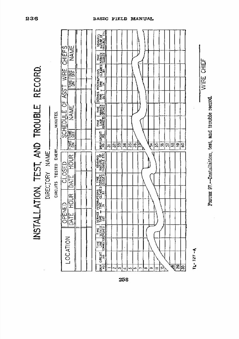
8/16/2019 (1942) FM 24-5 Signal Communication
http://slidepdf.com/reader/full/1942-fm-24-5-signal-communication 262/383
236
BASIC FIELD
MANUAL
u
U)
w
LI,
·
ú <
Cf)
4
_ 1 o
QW~~~~~~~~~~~~~~~~~~~~~~~~~~~~a
C)~~~~~~~~~~~~~~~~~~~~~~~~~~~~~~a
loZ
z
IM
ww
<
D
o
bii
u~
LoJ
4
1u,
I-1Zl
u>
UJ0
z
lii-Ll
0<
o
-~~~~~~~~~~~~~~~~~~-fl
H~~~~~~~5

8/16/2019 (1942) FM 24-5 Signal Communication
http://slidepdf.com/reader/full/1942-fm-24-5-signal-communication 263/383
SIGNAL
COMMUNICATION
236
(2)
The short
circuit
or "short"
is
caused
by electrical
contact
between the two conductors
of
a circuit. It
may be
the
result
of
bruised or
stripped
insulation
which
either per-
mits the bare
wires
to touch each other or
permits them to
conduct electricity
from
one to
the other
when wet.
(3)
The
grounded
circuit or
"ground"
occurs
when there
is
an
electrical path to
earth from one
or
both
conductors
of
the
circuit.
It also
may
be
the
result of
bruised
or
stripped
insulation
or
a poorly
taped splice where
the
wire
is lying
on
the
ground.
The
effects of grounds
will be
most pro-
nounced
in
wet
or
damp weather.
(4)
The
crossed
circuit
or "cross"
is
caused
by
electrical
contact between
conductors
of
two adjacent
circuits, and is
in reality a short
circuit
between
a
conductor
of one circuit
and a
conductor
of another.
c.
Effects
on telephone
transmission.-(1)
An
open
will
interrupt telephone communication
completely.
However, a
partial open,
such as
results
from a poorly
made
splice
or
a
loose
contact
which
introduces
a
high
resistance in
the
circuit,
may
not
destroy communication
completely, but the
transmission
will be
weak
and
probably
noisy.
(2) A heavy or low resistance
short
will
interrupt
telephone
communication
completely. A partial
or
high resistance
short will
result in weakened
transmission.
(3) A
ground on
both sides of
a
circuit
will produce an
effect
similar
to
that
of
a
short
described
in
(2)
above.
A
ground
on only one side
of a circuit will
not
usually
interrupt
telephone communication, but may produce hum
or noise in
the circuit.
(4) A
cross
is likely
to
result
in crosstalk
or interference
between the
two circuits
involved
which
may
or
may
not
be
sufficient
to
render the separate
conversations unintelligible.
d. Effects on simplex
telegraph operation.-It
will be ob-
served
that
a
simplex
telegraph channel may continue opera-
tive under
certain trouble conditions
which render the phys-
ical
circuit on which
it is
superimposed
inoperative
for
telephone
communication, thus;
emphasizing
again the
value of the simplex
telegraph
channel.
For
example,
the
simplex telegraph
circuit
will work, or
may
be
made to work,
by
the
addition of battery
in
the case of. the telegraph
set
259

8/16/2019 (1942) FM 24-5 Signal Communication
http://slidepdf.com/reader/full/1942-fm-24-5-signal-communication 264/383
236-237
BASIC
FIELD MANUAL
TG-5
or TG-5-A
even
though one side of the
physical
circuit
is open; a short on the physical
circuit
will
not affect the
telegraph
channel
adversely;
an accidental
ground
on one
or both
sides
of
the physical circuit
will
not render
the tele-
graph
channel
inoperative generally
unless
the
ground
is of
unusually low
resistance; a cross is not
likely to
interfere
with
the
telegraph
channel unless
both
of the
circuits involved
in
the cross
are
simplexed, and even then does not necessarily
render
the telegraph channels inoperative.
*
237. EQUIPMENT
USED FOR TESTING.-The
nature of the
trouble
on
a
field
wire
circuit
or
in operating
equipment
can
be determined with
any
of the
following
equipment in
the
manner described for
each:
a. Field telephones.-Any
field
telephone may
be used
for
testing
line
or
equipment
circuits. For convenience in mak-
ing tests
the telephone
is
equipped
with a
pair of
test
leads
made
of lamp
cord,
field wire, or
other
flexible twisted
pair
wire
about
3
feet
in
length.
A
test
clip
is
soldered
to
one
end of
each
conductor, and if
stranded
wire is
used the other
end which
is to be connected to the line terminal of
the
telephone
is soldered lightly
to
hold
the strands together and
prevent accidental
short
circuits
at
the
telephone terminals.
The
following
tests
may
be
made:
(1) Test
for
an open.-Connect the ends
of
the
circuit to
the line
terminals
of
the test
telephone
and turn the generator
crank
rapidly.
If
the
generator
crank
turns
quite freely
without any drag on
it the
circuit is
probably
open.
(2)
Test
for a
short.-With the
telephone connected
as
above, if the generator turns quite hard, as if a drag
had
been
placed
on
it,
the
circuit is probably short-circuited
or
grounded on
both sides.
(3)
Test for a ground.-Connect one side of the circuit to
one line
terminal of
the telephone,
and
connect
the other
line
terminal of
the telephone to ground. If there is
a
ground
on
that side of the circuit,
the generator
will turn
hard as
in
the
case of a
short. Test
the
other side
of the circuit
in
a
similar
manner.
(4) Test
for
a cross.-Connect one side of the circuit to
one
line
terminal of
the telephone
and
the
other
line terminal
of the
telephone to the conductor with which the circuit
may
260

8/16/2019 (1942) FM 24-5 Signal Communication
http://slidepdf.com/reader/full/1942-fm-24-5-signal-communication 265/383
SIGNAL
COMMUNICATION
237
be
crossed.
If
there
is
a
cross
the
generator
will
turn
hard
as
in
the
case
of
a short
circuit.
Test
each
side
of
the
circuit
in a
similar
manner
with
any
conductor
with
which
it
might
be
crossed.
b.
Test
sets
EE-65-A
and
EE-65.-The
test
sets
EE-65-A
and
EE-65
are
compact
wire
chief's
testing
equipment
for
f~~~a~i"~
7Z-3304
_rauER
98.-Test
set
EE-65-A.
use
in
the
field
or
in
central
office
installations.
The
test
set
EE-65-A
is
illustrated
in
figure
98.
In
addition
to
means
for
ringing
and
talking
on
field
wire
systems,
both
test
sets
have
provisions
for
the
usual
measurements
required
for
analysis
of
faulty
line
operation.
These
include
tests
for
continuity,
opens,
shorts,
grounds,
and
other
more
specialized
applications
such
as determinations
of
line
capacitance
and
leakage.
The
principal
differences
between
the
two
test
sets
are
that
the
EE-65-A
has
the
more
sensitive
voltmeter
and
has no
telephone
handset
included
with
the
instrument.
For
261

8/16/2019 (1942) FM 24-5 Signal Communication
http://slidepdf.com/reader/full/1942-fm-24-5-signal-communication 266/383
237
BASIC
FIELD
MANUAL
a complete
description
and
circuit diagrams
of
the test sets
EE-65-A
and
EE-65,
see TM
11-361.
c.
Voltmeter
and
battery
(fig.
99).-A
simple
arrangement
for testing
equipment circuits
consists of a voltmeter and
battery connected in series and equipped with wire leads.
The terminals of
the wire
leads
may
be fitted either with
test clips
or
short lengths of stiff copper wire for convenience
in making contacts with the equipment
circuits. This
appa-
ratus
is
suitable for making the following tests:
3 Amps
/sAmps
30..,p
MIGURE 99.-Voltmeter and battery for use in testing circuits.
(1) Test for a complete circuit-Connect the test leads
to
the
ends
of the
circuit
to be
tested.
If the
circuit is
complete
the
voltmeter
needie will indicate
a
reading.
(2)
Test for an
open.-Connect
the
test
leads
to
the ends
of
the
circuit
to
be
tested.
If the
circuit
is
open,
the
volt-
meter
needle
will not
indicate a reading.
(3)
Test for a short.-Connect the
test
leads
to the
ends
of
the circuit
to be
tested.
Open
the
other
end
of
the circuit.
If
a short circuit exists, the results noted will be the
same as
for a
complete circuit
((1)
above).
(4) Test
for
a ground.-Connect
one
test
lead
to
the cir-
cuit
to
be
tested.
Connect the other test lead to ground. If
the
circuit
is
grounded,
the results
noted Will be
the
same as
for a complete
circuit
((1) above).
(5) Test
for
a cross.-Connect
one
test lead
to
the circuit
to be tested. Connect the
other
test
lead to the
circuit with
which
the circuit to be
tested
is believed to
be crossed. If
one is crossed
with
the other, the
results
noted will be the
same as
for
a
complete
circuit
((1) above).
262

8/16/2019 (1942) FM 24-5 Signal Communication
http://slidepdf.com/reader/full/1942-fm-24-5-signal-communication 267/383
SIGNAL
COMMUNICATION
237-238
d.
Receiver
and
battery
(fig. 100).-A
telephone
switch-
board
receiver
connected
in
series
with
a battery
and
fitted
with
leads
may
also
be
used
for
testing.
The terminals
of
the
test
leads
may
be
either test
clips
or
short
lengths
of
stiff
copper
wire.
The apparatus
is
suitable
for making
the
tests
TE
T
CLIP
TEST/NG
LEADS
B A R E
W5/IE
PO/NT
TL-739
FIGURE
100.-Receiver
and
battery
connected
for
use in
testing
circuits.
outlined
for the
voltmeter
and
battery
in c above.
However,
a
click in
the receiver
instead
of a
reading
indicates
a com-
plete
circuit.
A
failure
to
obtain a
distinct
click
on complet-
ing the
circuit
indicates
an open
circuit.
*
238.
LOCATING
AND
CLEARING
TROUBLE.--a.
General
localizing
of trouble.--When
trouble
is
detected
or
reported
on
a
cir-
cuit,
the
first step
is to
determine whether
it
is
in
the
line
wire
itself
or
in the
operating
equipment.
If
the line
wire
is
cleared
from
the
terminal
equipment
at
the terminal
strip,
tests
made
from
that
point toward
the
switchboard
show
no
trouble
in the
operating
equipment,
the
trouble
may be
assumed
to be
either
in the
line
wire itself
or
in the
operating
equipment
at
the
distant end.
This
is
verified
by
connecting
the
test
equipment to
the line
and
testing
toward
the
distant
end
of the
circuit.
Trouble
on
a
trunk
circuit
may
be still
further
localized,
providing
an
additional
good
circuit is
available,
by
requesting
the
wire chief
at
the
distant
end
to
clear
the faulty
circuit
from
the
operating
equipment
at
that
end.
The circuit
is
then tested
again
for
an
open
with
the
distant
ends
of the
circuit
open,
and
for a complete
circuit
263
8/16/2019 (1942) FM 24-5 Signal Communication
http://slidepdf.com/reader/full/1942-fm-24-5-signal-communication 268/383
238
BASIC FIELD
MANUAL
with
the distant
ends of
the
circuit connected
together.
If
the trouble
is in
the
line
wire
itself
it will
appear
upon
making
these
tests,
and it
is located
and
cleared
as described
in
d
below.
If these tests
show
the
line
wires
to
be
good,
the
trouble
is
in
the
operating
equipment
at
the
distant
end
and
the
wire chief
there
is
so
notified
and
requested
to
clear
the
trouble and
reconnect
the
circuit.
b. Short
local
circuit
in
trouble.-If,
upon
making
the first
test
described
in
a above
at
the
terminal
strips,
the trouble
is
found
to
be
toward
the
user's
telephone,
the
circuit
is
recon-
nected
and
a trouble
man
dispatched with
a serviceable
tele-
phone
to the
user's instrument.
On
his way
he
inspects the
circuit
for visible
sources
of
trouble
and
repairs
any
that
he
finds.
He
then
makes
a
ringing
and
talking
test
with
the
user's
telephone.
If
he cannot
signal the
operator
with it,
he replaces
the local
instrument
with
his own
instrument
and
repeats
the
test.
If
he
can
now
signal
and
converse
with
the operator,
the
trouble was
in
the
local
telephone
which
is
either
repaired
or
replaced
by
him.
If
he
cannot
signal
the
operator,
the
trouble is
probably
in the
local
line
circuit,
and
he
first
tests
for
a
short
and an
open
circuit,
then
tests
for
a
grounded
circuit,
and,
if applicable,
tests
for
a cross
with
another
circuit.
If
trouble
is located
in
the
line
wire,
he
works
back
toward
the
switching
central,
making
a
careful
inspection
of
the
line wire,
paying
especial
attention
to
splices
and
other
doubtful
points
over its
entire
lenzth.
If
the
fault
is
located,
he
repairs
it
and
notifies
the
uscr
that the
service
is
again
available.
If
careful
inspection
does not
readily
disclose
the
fault, time
may be
saved
by
running
a new
circuit.
This
circuit
is then
connected
into
the
switchboard,
the
local
telephone
connected
at
the
end
of
the
circuit, and
the
new
installation
tested.
c. Trunk
circuit
or
long
local
circuit
in trouble.-(1)
If
the
tests
described
in
a
above
determine
that
the
trouble
is
in
the line wire
of a trunk
circuit
or in
a long
local
circuit,
the
wire
chief
determines
as accurately
as
his
instruments
permit
the
nature
and
approximate
location
of
the
trouble.
This
will
facilitate
the
testing
and
materially
shorten
the
time
required
to locate
and
clear
the
trouble.
(2)
The
circuit
is
then
connected
to a
test
telephone
at
the
264
8/16/2019 (1942) FM 24-5 Signal Communication
http://slidepdf.com/reader/full/1942-fm-24-5-signal-communication 269/383
SIGNAL
COMMUNICATION
238
switchboard
terminal strip
or left connected
into
the switch-
board
if there
is not sufficient
maintenance
personnel
avail-
able
to
man the
test telephone.
A
lineman
is
then
sent out
on
the
line
with
a
test
telephone
to
test
methodically from
various
points back
to
the man
at
the switchboard
terminal
strip or
to the
switchboard
operator.
Starting
from
the
switchboard
terminal strip,
he
carefully
examines
the
circuit
as he
proceeds,
particularly scrutinizing
the insulation,
splices,
underground
and
overhead road
crossings,
and places where
the wire has
been
passed
over
or
pulled
out of place
by
trafflc.
Fouled
insulation, poor
splices,
and
other
evidences of possible
trouble are
repaired
and
the circuit
tested
in
order
to
deter-
mine
if the trouble
has been
cleared. If no
such points
of
obvious
trouble
are
found,
the lineman
bridges his
telephone
across
the
circuit
at
intervals
and
tests.
(3)
If
testing
the defective
circuit for
an
open, he
connects
the
test telephone
across the
circuit
without
opening
it.
If
testing
for a
ground
or a
short,
he opens the
circuit
and then
tests
in
both directions.
Before opening
the
circuit
however,
he connects
his telephone
to it
with
the test
clips and
attempts
to communicate
in
either direction
as there
is a possibility
that
the trouble has
been cleared in the
meantime by other
personnel.
In
case it
is necessary
to
open
the
circuit, it
is
opened
at a splice
or at
a test station
if practicable.
After
making
each
test the
circuit
is
reconditioned
by taping
wher-
ever
a
test
clip
has
been connected
to
it,
or
by
splicing and
taping
wherever
the wire
was
cut.
(4) Upon
making
each
test
the lineman
himself
can deter-
mine whether
the
circuit
is good
between
his
location
and
the central by his ability
to
ring
and talk to the
man
at
the
switchboard
terminal strip
or
the operator.
If any test
to-
ward
his
own central
is
successful,
the
fault still
lies beyond
in
the direction
of the
distant
central
and
the lineman
con-
tinues
to
work
in
that
direction.
If
he
is
unsuccessful
in
reaching
his
own central
during
any
test,
he
has
passed
the
fault
and
therefore works
back
over
the
circuit,
reducing the
distance
between
successive
tests
to about
one half.
By fol-
lowing this
procedure
the fault
is located
between two points
a short distance
apart.
This
section
of the
line
is
then
care-
fully
inspected until
the
actual
fault
is
located.
It is then
265

8/16/2019 (1942) FM 24-5 Signal Communication
http://slidepdf.com/reader/full/1942-fm-24-5-signal-communication 270/383
238
BASIC
FIELD MANUAL
repaired
by splicing,
by
cutting
out and replacing
the
faulty
section,
or by
simply
taping
as
required.
(5)
A
defective
circuit
may have
more
than
one
fault.
These
may
be
of the same nature
or
different.
It is essential
that
the lineman, after
clearing each
case
of
trouble,
test
the
circuit in
both
directions to insure
that
it is in order. If
trouble
still
exists
he
continues his
inspection
until
all
trouble
has been located
and
cleared.
(6) The
time
consumed
in
splicing a
circuit after
each test
for a shirt or
ground
is
considerable, and will seriously delay
the
ultimate
locating
of
a
fault
if
such tests are made
at
too
frequent
intervals
along the circuit
when first
starting out.
Furthermore, a
visual inspection
of the circuit by the lineman
as he progresses
along
its route
will
frequently disclose
the
fault. A knowledge
of
the
geographic
location
of
a circuit
will
aid the wire
chief in predicting
the
probable
location of
a
fault,
having
determined its
nature. He may
direct the line-
man to
make
tests from the vicinity
of
such
points or
may
specify the
approximate
interval for making tests.
A
good
rule
is to
test each time
a
portion of the
circuit
has been
passed which
could not be visually
inspected.
d. Removing
trouble.-In repairing
a circuit
in the field,
speed
in restoring
service comes first
and
proper
technique
in splicing
next.
When
repairing a break
in a line,
communi-
cation is
first
restored
by
completing
the
square
knot
in
each
wire.
Then
while
the
bare
wires
are
kept separated
to
prevent
a short
circuit,
the
splice is completed and
taped.
A valuable addition to
the equipment of
a
lineman con-
sists of two short
pieces
of wire
about
3 feet
in
length
with
test clips on
each end. These
jumper
wires
are used
to
bridge
a break during
the construction
of a splice,
thus
keeping the
circuit
in operation.
In
using
jumper wires,
care
is
taken
that a
short
circuit is
not caused
while splicing.
In
locating trouble,
linemen,
preferably from
the
unit
originally
constructing
the line,
are sent
out from each
end
of the
cir-
cuit
and work
toward each other. The wire chiefs
at
both
ends are responsible that it is
cleared,
regardless
of
where
the trouble
was
first
discovered. In
addition to
pliers,
tape,
and test
telephone,
each lineman carries
a
50-foot
coil
of
field
wire with which to repair
defective sections.
266

8/16/2019 (1942) FM 24-5 Signal Communication
http://slidepdf.com/reader/full/1942-fm-24-5-signal-communication 271/383
SIGNAL COMMUNICATION 238-239
e. Trouble in local
operating
equipment.-If
the
trouble
was originally determined to be toward the operating equip-
ment
at the central, it
may
be localized by opening
the
circuit
at
various
places
such
as
the
line
terminals,
fuses,
protectors, etc.,
and
the tests repeated. Terminal strips
and
connections
are
inspected
carefully for
"shorts,"
"opens," and
"crosses."
If
the
trouble is in the equipment itself it can
be
located
by a rigid system of testing
such
as
prescribed
for
that
specific piece of
equipment
elsewhere
in this manual
or
in the
Technical
Manuals
relating thereto.
In
the case
of a
faulty
unit
in
a switchboard,
its use
should be
dis-
continued
and the circuit transferred
to
a
spare
unit
until
repair
or
replacement can be made.
* 239. OPERATION OF TEST
STATIONS (pars.
174 and
200).-a.
The personnel at
a
test
station may
consist of one
or
more
linemen as the
situation
requires.
When
the talking range
will not be affected adversely, a test
telephone may
be kept
bridged
across a
circuit, usually
the
lowest
numbered
tele-
phone circuit
passing
through
the test
station,
or
a
special
circuit
ending
at
the test
station
may
be temporarily
reserved
for test
purposes. The personnel on duty at the test
sta-
tion
is
instructed to
answer
prearranged signals
only,
usu-
ally three short
rings. When
answering this prearranged
signal, the test station personnel
states the name of the
test
station. The test station
personnel is
then instructed
as
to patching,
testing,
or
repairing
circuits,
as
the situation
requires.
b. Test station personnel
keeps informed
constantly as
to
the
serviceability
of
the circuit
across
which
the
test
tele-
phone
is bridged by listening
for the
normal
signaling
and
conversation
that is
passed
over the
circuit.
If the circuit
becomes
idle
it
is tested
promptly,
and
frequently thereafter.
If
these tests show the
test circuit
to be
in trouble,
the
test
telephone
is
bridged
across
another
circuit and
a
report
made to the
switchboard
operator
or the wire chief.
c. Locating
and
clearing trouble on
defective
circuits which
pass
through test stations manned by
linemen
is
facilitated
by
the fact that the wire chief can call each successive
test
station
and
quickly determine
the faulty section. The
near-
est test
station can then
be directed
to
dispatch a lineman
to
267

8/16/2019 (1942) FM 24-5 Signal Communication
http://slidepdf.com/reader/full/1942-fm-24-5-signal-communication 272/383

8/16/2019 (1942) FM 24-5 Signal Communication
http://slidepdf.com/reader/full/1942-fm-24-5-signal-communication 273/383
SIGNAL
COMMUNICATION
241-242
E 241. PATROLLING
WIRE
LINES.-In shelled
areas
or
where
wire lines
are subject
to frequent
damage
from
other causes,
periodic
testing
from designated
points
is
supplemented
by
patrolling
the
sections
most subject to
damage.
Whenever
possible,
the
personnel that
have
constructed
a
given section
are
also
assigned the mission
of
patrolling that section.
Wire patrols
to be effective must carefully
inspect
every foot
of the
wire in the sections
they cover, using
a
wire pike or
an
improvised
wire guide
made
by
fastening a
bridle
ring to
a
hand
grip.
Wire patrols
repair
trouble
whenever
found.
They
replace
doubtful
splices
or
sections
of
the
line,
tape
abrasions in
insulation,
and
improve
the
construction.
E
242.
TESTING
FIELD WIRE
ON
REELS.-All
insulated
wire is
carefully reconditioned
after
use, as follows:
a.
Mount
an
empty reel
and
the
reel
containing
the wire
to be
tested,
so
that the
wire
may
be
wound from the
full
reel
on to the
empty
reel.
b.
Pass the
end
of the wire
through
the
hole provided
near
the
drum
of
the
empty
reel
and
secure
it
so
that
the
end
will protrude
from the side
of the reel
This
end
must
be
free for use in
future
testing.
c. Station
an experienced man between
the reels to exam-
ine the wire
carefully
as it is
slowly wound on
to
the empty
reel.
Cover
with tape each
abrasion
or break
in
the
insula-
tion.
If only
the
braid is broken, apply
two layers
of
friction
tape.
If
the
bare
wire
is
exposed,
remove
the
ragged
portions
of
insulation and
cover
the
wire
with two layers
of rubber
tape
and
two layers of friction
tape as
described
in
para-
graph 187b.
Carefully
splice
breaks
in
the conductor.
Un-
tape and
examine
each
old splice;
if
the
splice
is poorly
made,
cut it out
and splice the wire
properly. If
the
insula-
tion has been
damaged
over a long section
of the wire, or
if
there are several
splices very
close
together,
cut out
the
faulty
section.
d.
After
each splice, and
also
when all the
wire of a reel
is
completely repaired,
test the wire
on
the reel being
filled for
an
open circuit
or
a
short
circuit between
the two
wires.
These
tests
may be
made by
any
of the equipment
described
in paragraph
236.
556773--43
-18
269
8/16/2019 (1942) FM 24-5 Signal Communication
http://slidepdf.com/reader/full/1942-fm-24-5-signal-communication 274/383
243
BASIC
FIELD
MANUAL
* 243. TRANSPORTATION
OF
WIRE EQUIPMENT
IN
FIELD.-a.
O p-
erating equipment.-Operating
equipment
is
comparatively
delicate and its
serviceability
is
governed
to a
great
extent
by
care in methods of packing
it for transportation.
Operat-
ing equipment
is packed
and loaded in
such manner
as to
protect
it from-
(1)
Dust
and
dirt.
(2)
Weather.
(3)
Shocks
of the road.
(4)
Injury from
other
articles loaded in
the same vehicle.
b.
Telephones.-Field
telephones
are
carried
in
pack chests
when
these
are
provided.
Handsets
ánd cords are always
placed
neatly
in
their
proper compartments,
hook
switches
and removable
generator
cranks placed
inside the
cases, and
carrying
cases
closed
and
locked or
strapped.
Special
care
must be taken to keep
push
buttons
or
butterfly
switches
on
telephone
handsets in the "off" or undeflected position to
prevent
useless
drain on batteries.
c.
Switchboards.-Monocord
switchboards
with cable and
switchboard
terminal strip attached
are
packed
in
a
pack
chest
separate
from
telephones.
Before placing
in
the pack
chest
the
switchboards
are
placed
in their
carrying
cases
with
shutters locked
and
cable neatly coiled.
d. Repeating
coils, loading coils,
terminal strips, spare
bat-
teries,
and
spare
parts.-These
are carried in the pack chests
provided,
packed
in
such
manner
as
to prevent
injury
to
them-
selves
or
other
equipment in
the
same chest.
e. Telegraph
and
buzzerphone
sets.-When pack
chests
are
available
it is desirable
to use them: for packing this equip-
ment as loads that
are
more
compact
and easily handled
result from their use. The cases
of buzzerphones
are
of
more
sturdy
construction and
they may
be
packed outside
of special
pack
chests
without
danger of injury.
f.
Wire.-The
principal precaution necessary
in
transport-
ing
wire is
that
the metal
drums
or commercial spools should
not
be
dropped from
vehicles
or
handled in such a manner
as to injure or
bend them
and
thereby
make
difficult
their
refilling and use.
The
wire should be protected from
crushing
or
abrasion from
other
objects transported
with
the
reels.
270

8/16/2019 (1942) FM 24-5 Signal Communication
http://slidepdf.com/reader/full/1942-fm-24-5-signal-communication 275/383
CHAPTER 9
SIGNAL SUPPLY
*
244.
GENERAL.-POr general
information
regarding supply,
see FM 100-10.
a.
Signal supply is
conveniently
discussed
in
terms
of
the
division and the supply duties of the division
signal
officer.
Signal
supply of corps
troops
is effected by the same methods
as are employed in the division, the duties of the corps signal
officer
in
this respect
being analogous to
those
of
the
division
signal officer. Signal supply for army troops
and
GHQ troops
is
accomplished
in a similar manner.
See paragraph 254
for
signal supply of
air force troops.
b.
Responsibilities
of
commanders for
signal
supply
of
their
troops
are the same as for other supply.
The principal
supply
duties of
a division signal officer are
given
in paragraph 12
and the
most
important
publications
relating to
signal supply
are
included in appendix II.
U
245. CLASSIFICATIoN.-All items of signal communication
equipment, except pyrotechnics and pyrotechnic projectors,
are
classed
as
signal
supplies.
These excepted
items are
ord-
nance
property
and are
handled
through
ordnance channels.
All signal
supplies issued to
division units
are
normally class II
and the methods of procurement described below are based
on
this
premise. Some signal supplies
properly
fall
into
class
IV. Special
materials for cable, pole, and trench line
construction,
and
for radio
and other installations not usual
within
the division fall into this
latter
classification.
Such
materials
are
commonly
used
by
Signal
Corps
troops
or
corps
and
higher echelons,
and occasionally by troops of other arms.
271
8/16/2019 (1942) FM 24-5 Signal Communication
http://slidepdf.com/reader/full/1942-fm-24-5-signal-communication 276/383
246-247
BASIC
FIELD
MANUAL
*
246.
DIVISIoN
PERSONNEL.-The
supply
officer
of
the division
signal company
or troop
is the principal
supply
assistant of
the
division
signal
officer.
The
supply
and transportation
personnel
and
facilities
of
the
company
or
troop are
utilized
for
division
as well
as for company
or troop
supply purposes.
Supply
officers of
all
division units
may
deal
directly
with
the
division
signal
officer
on
signal supply
matters
within
the
limits of policies
prescribed
by the
commanders
concerned.
*
247.
METHOD.-The
impulse for
signal, like
other
supplies,
is from
rear
to front.
Any expediency
which
can
be
adopted
to
expedite
supply,
particularly
in
the
theater
of
operations,
should
be vigorously
enforced.
To reduce
formal paper
work,
full advantage
should 'be
taken of provisions
of
AR 35-6540,
which
authorize the
exchange of
serviceable
for
unserviceable
articles.
In the
theater
of
operations, radio
and telegraphic
messages, or,
in an emergency,
even
oral or telephonic
mes-
sages, may suffice
for
requisitions. In
such case,
an
explana-
tion of the
need for
such articles
may
be
required
by the
approving
authority,
especially
when
the articles
requested
are
in excess of
T/BA allowances.
The
supply
approval
deci-
sion
should be
based upon
a careful
consideration
of
the
expressed
need for supplies
in contradiction
to
any
special
formial
allowance.
Stocks
available
and priority of
need
are
the main
controlling
features.
a. Normal
requisitions
are
reduced
to
a
single
request
by
the
consolidation
of
needs
within
any
unit.
Emergency
requisitions
may
be
submitted at
any
time. A
requisition
or
request for
supplies which
has been
accepted
by a higher
office
must
be
followed up vigorously
to
see
that every effort
is
made to secure
them, and
that any action
taken
or
results
obtained
is
transmitted
to
the
requesting authority. Hence,
no
unit
should
duplicate on
later
requisition
items
previously
aquested
unless
they
have
been informed
that such
items
have
been
stricken from
the
original requisition.
b. Requisitions
or
requests
are
submitted
to
the division
signal
offlcer by the
unit
supply
officer.
Each
requisition
includes
the
consolidated
needs of the
unit.
A signal
com-
pany
or troop
submits
requisitions
or
requests
the
same
as
any
other unit.
c. Requisitions
or
requests
should
be for
supplies
within
272
8/16/2019 (1942) FM 24-5 Signal Communication
http://slidepdf.com/reader/full/1942-fm-24-5-signal-communication 277/383
8/16/2019 (1942) FM 24-5 Signal Communication
http://slidepdf.com/reader/full/1942-fm-24-5-signal-communication 278/383
249-251
BASIC
FIELD MANUAL
for signal
supplies. Usually units
send
their
transporta-
tion
to
the
signal supply dump.
When
drawing
against
credits, an informal
request
for
the
items desired, signed
by
the unit
supply
officer,
should accompany
the transporta-
tion. In the
combat zone
where accountability is
suspended,
the
supply officer
includes on
his
receipt for
the
property
a
notation
of the organization
and
purpose, or
work,
for
which the supplies or materials are
to
be
used.
When
unit
transportation is not
available, cargo vehicles
available to
the
division
commander are
used to deliver
supplies to the subor-
dinate
units. In
an
emergency,
the division
commander
may
direct
the
use
of
transportation
of
the
signal company or
troop for this purpose.
When
possible,
supplies
are delivered
to unit distributing points where supply officers make any
additional distribution
which may
be desired.
* 250. SIGNAL UNIT
SUPPLIES.-The
quantities of
signal
sup-
plies
authorized
for the division
signal company
and
troop
are
the
minimum
necessary for their
proper functions, and
the
use
of
those
supplies
to
meet
the
needs
of
other
units
is
not normal. However, in unusual situations,
emergency
needs
of lower units are
balanced
by
the
signal
officer against
those
of the signal
company or
troop, and
if
necessary,
are met
to
some extent from
those
supplies.
In such cases immediate
action
is initiated to
replenish
the
supplies so
issued. To re-
lease the train of the division signal
company or
troop for its
combat mission,
it is
necessary to dump
some or all of the
unit supplies at a point
convenient
to the
unit.
This
point
is located
near
the division command post.
*
251.
STORAGE
BATTERIES.---.
In
units
not
equipped with
charging sets, the storage
batteries
authorized
solely
for use
with
communication equipment
are serviced by
the
division
signal
company or
troop.
b. The division signal
officer
provides for
the collection,
charging, and distribution
of
these
batteries.
Batteries
should
always be
fully charged
before
the
beginning
of
a
tactical operation.
c.
The charging
and
maintenance of storage batteries in-
stalled in
a vehicle and used
jointly
in
the operation of
the
vehicle
and
of
signal
equipment
installed therein
is the re-
274

8/16/2019 (1942) FM 24-5 Signal Communication
http://slidepdf.com/reader/full/1942-fm-24-5-signal-communication 279/383
SIGNAL
COMMUNICATION
251-254
sponsibility
of the arm or service
charged
by
AR
850-15
with
the maintenance
of the
vehicle.
d. For
further details,
see
TM
11-430.
*
252.
PIGEoNs.-Pigeons
are
distributed as prescribed
in
paragraph
92a.
*
253. REPAIR OF
EQuPMENT.-While
much
of
the
signal
equipment
issued is simple and
usually
needs only minor
mechanical or electrical repair, other items are inherently as
delicate
as
precision
instruments and
require
the attention of
expert
repairmen.
The attempted repair of the latter
equip-
ment
by
an incapable
repairman
often
results
in
greater
damage to the
equipment.
The
Signal Corps General Cata-
log
and
Technical Manuals
provide
guides to
the
repairs
which
should be attempted
in the field. Repairs
are accom-
plished as follows:
a. The extent
to
which repairs are permitted in any unit
is
determined
by the
commander
of
the
unit after the receipt
of
advice
from
the
division signal
officer.
This
determination
is made
only
after
a
consideration
of
the
tools and testing
equipment
available
in the unit and of the
capabilities
of
available
personnel.
b.
Using
units
habitually
replace unserviceable
batteries,
cords,
tubes, easily accessible assemblies, nuts, bolts,
screws,
straps, and other simple
mechanical parts.
c.
Equipment which
is
not repaired
in
lower units
is
turned
in
for
repair
or replacement
to
the
division
signal
company
or
troop which
has
limited
but usually
better
repair personnel
and
facilities.
If needed repairs are beyond
the
immediate
capabilities of
those units,
the signal
officer
takes
immediate
steps
to secure replacement
and forward the
unserviceable
item
to the army
signal
depot or to a mobile repair shop of
the
army signal
repair company
when
the division is part
of
an
army, or disposes of it in
accordance
with instructions of
higher
authority
when
it
is
not.
* 254.
SIGNAL
SUPPLY
FOR
ARMY AIR
FORCES.-a.
Organization
for supply.-Supply for air
force
units
is described
in FM
100-10. The organization
for
supply of air force units, which
is
shown
graphically in figure
102, follows
the
chain
of ground
installations rather
than
the chain of command. The air
275

8/16/2019 (1942) FM 24-5 Signal Communication
http://slidepdf.com/reader/full/1942-fm-24-5-signal-communication 280/383
254
BASIC
FIELD
MANUAL
no'
Raddar
' o
umomcañons I Rrr«£.e
rzGo
./ In
and
2ad
Sc
m m n/ic8r/ons.
l - -
l
rqguirmenit
f l
t
_e
and foI.
Gmrov. o i /ezerl
-. ,lllCfl
---
'-
vpp/y
--- -
,eepm/r
rz-
a,7g3
FmrnE 102..--Flow
of
supplies In
an
air
force.
force signal
oflcer
is responsible
for
proper
operation
of
signal
supply
in
the
air force
and
the
signal
offic
of each
com-
mand echelon
is
responsible for assuring
himself
that
signal
supply
requirements of all units
of his
echelon
are being
met
and for
making
reports and recommendations
for improving
this
service.
b.
Signal
supply
oicers.-Signal
Corps
officers are provided
for
signal
supply down to include
the subair base.
Down to
this
point,
accountability
and
the process
of
requisitions
and
shipments
of property are
maintained.
Below the
subair
base,
requisitions
are informal
and
property is
held
on mem-
orandum
receipt. Full
advantage
is
taken
of
the
exchange
of
property provisions of
AR 35-6540. Every
authorized
pro-
cedure
which
will facilitate
supply
is followed.
c.
Method.-If,
in the air force
squadron, authorized
non-
expendable
property
becomes unserviceable
through
fair
wear
and tear,
the
squadron
supply
officer executes an
infor-
mal certificate
of
fair wear
and tear and with
an informal
requisition
for
replacement
of
the
equipment submits
it
to
the
air
force
distributing
point
officer.
The
distributing
point
officer
exchanges the unserviceable
item
for a like
serviceable
item
in his
stock whenever
possible.
If he
does
not have the
item
in
stock,
he
informally
requisitions
the
item from his
subair
base signal
supply
officer accompanying
the requisition
with
the
squadron supply
officer's
informal
certificate
of fair
wear and tear
and also
the item when
practicable.
276

8/16/2019 (1942) FM 24-5 Signal Communication
http://slidepdf.com/reader/full/1942-fm-24-5-signal-communication 281/383
SIGNAL
COMMUNICATION
254
d. Source.-The
appropriate
section of
an
air
force
base
command
serving
an
air support
command is
the
agency
charged
with
maintaining
appropriate
reserve stocks
of signal
supplies and
issuing
them
to
the
signal
communication
units
to the extent
of allotments provided
in
the
Tables
of
Basic
Allowances,
in the
first instance, and
thereafter
as
replace-
ments are required.
e.
Expendable
and
nonexpendable
items.-Expendable
items
of
signal
supplies and
equipment
will be
replaced
by
the sup-
ply
agency
upon
presentation
to it
by
the
signal or
com-
munication
unit
concerned
a duly
executed
certificate
of
ex-
penditure, listing
thereon the
expendable
items to
be
replaced.
Unserviceable
expendable
and
nonexpendable
items will
be
turned
in to the
signal supply
agency
accompanied
by a
duly
executed
certificate
of fair wear
and tear,
and the
items
will
be
replaced. The
certificate in
each instance
will serve as a
requisition.
f. Repair of equipment.-Minor
repairs only
of
signal
equip-
ment,
and
only
within
the
facilities
and
means
available,
will
be undertaken
by
signal
and
communication
units. Equip-
ment
in
need
of
repair
will be turned
in to the signal
supply
agency accompanied
by
a
certificate
of fair
wear and tear
and replacement
will
be
furnished.
277
8/16/2019 (1942) FM 24-5 Signal Communication
http://slidepdf.com/reader/full/1942-fm-24-5-signal-communication 282/383
CHAPTER 10
ORDERS, RECORDS,
AND
REPORTS
*
255.
REFERENCES.-For further information on this subject,
see
FM 101-5
and FM 11-5.
1
256.
ORDERS.-Signal
communication personnel
are
re-
quired
to
interpret and execute the
instructions
contained
in
routine and
combat
orders.
(See FM
101-5
for
classifi-
cation of orders and forms.)
9 257. RECORDS AND
REPORTS.-a.
Unit
journal.-Signal
units
of division and higher headquarters keep a journal
during
operations in
the
field.
The journal
is
a daybook
containing
briefs
of
important
written
and
oral
messages received
and
sent and
notations
of
periodic
reports, orders, and similar
matters that pertain directly
to the
signal
unit. Copies of
messages and other data pertaining
to the
signal unit
and
furnished
by
it
for
purposes of
information to
sections
of
the
unit
are not entered in the journal.
Communication
units
may
keep a
similar journal
but rarely
find it necessary
to
do
so.
(See
form
for a signal unit journal
in
par. 261.)
b.
Circuit diagram.-A
consolidated circuit diagram
is
kept
by signal communication troops of
the
unit headquarters
to
show the wire
system
of
the
unit and
those
of its subordi-
nate units. A
circuit
diagram also serves
as
a convenient
method of
reporting
to the next superior
headquarters
the
circuit connections
installed by
the
subordinate
unit. (See
pars. 167
and 262.)
c. Line
route
map.-A
consolidated
line
route
map
is kept
by signal communication troops of the unit headquarters to
show
the routes of the wire lines of
the unit
and
those
of
its subordinate units.
A line route map also
serves
as
a
practical and convenient method of reporting
to
the
next
superior headquarters
the
routes of the wire lines installed
by the subordinate unit. (See pars. 169 and 263.)
278

8/16/2019 (1942) FM 24-5 Signal Communication
http://slidepdf.com/reader/full/1942-fm-24-5-signal-communication 283/383
SIGNAL
COMMUNICATION
257-258
d. Disposition.-The
signal or communication
officer
ar-
ranges
for
the
collection of message
center
records,
switching
central
records,
and
records
of
radio
and
telegraph
stations,
and other operating
agencies from each
operating
agency at
frequent
or at
least
daily
intervals.
(See
par. 46d.)
Such
records
are
useful
for
the
correction
of errors,
checking
on
operation,
or for
information
for special reports.
When of
no
use, they
are destroyed.
P 258. STEPS INVOLVED IN EAC}I
TACTICAL
OPERATION.-The
solution
of
any
situation demanding action
requires
that
cer-
tain
definite
steps
be
taken
in
a
logical
sequence.
a.
Mission.-The
signal mission is the particular duty
re-
quired
of
signal
communication
troops. The
commander
may
give
his
signal or communication officer definite instruc-
tions as
to what
signal communication
he desires
or
he
may
restrict the
mission
of the signal or
communication officer
by
directing that
only certain agencies be employed. In most
cases,
however,
this
mission
is
seldom
stated
by
the
com-
mander. It
is more
or less routine and
is
usually deduced
from the commander's
directive to his
staff.
b. Estimate
of the signal situation.-The
signal
or
commu-
nication officer
makes
an
estimate
of the signal
communica-
tion situation in
order to
arrive at
his recommendations
concerning the signal activities of the command.
He
first
considers
his
mission; he
next
considers
so
much
of
the
enemy
situation
as
may
affect
his
commander's
signal
com-
munication;
then the
tactical
decision and so
much
of the
friendly
situation,
including the
signal situation,
as has a
bearing
on
the
furnishing of the
signal communication
de-
sired for the operation;
and
last, the several plans open to
the
commander
for
providing adequate
signal
communication
for the contemplated tactical
operation. From
as com-
plete
an analysis of
these
considerations
as time permits,
the
signal
or
communication
officer
makes
his
decision
as
to the
recommendations
he will
make
to his
commander for
providing signal communication
for
the tactical
operation
planned.
e. Plan.-When
time
permits,
the recommendations
are
submitted
to the
commander
in the
form
of
a plan for
signal
communication.
Whether
or
not
the time
necessary
to
279
8/16/2019 (1942) FM 24-5 Signal Communication
http://slidepdf.com/reader/full/1942-fm-24-5-signal-communication 284/383
258
BASIC
FIELD
MANUAL
evolve
and
obtain approval
for
a
communication
plan
will be
available
will
depend
on the tactical situation. In
any
event
the
steps
in
evolving
the
plan
are
followed
whether
they
are
transcribed
as a formal written order
or
are issued
as
an
oral
or
dictated order, fragmentary
or complete.
Whether
or
not
the
plan
is
submitted to
the commander
or
to
his
G-3
(S-3)
depends
upon
the
operating
methods
of the particular staff.
Since
G3
(S-3)
is charged with supervision of
signal com-
munication, it is considered better practice to first submit
the
plan to him.
The plan presented
will
comprise the
following:
(1) Paragraph
5 of
the field order.
(See
par. 259a.)
(2) Time the signal
system will
be
ready
for
operation.
(3) Essential service
to be provided.
(4)
Signal supply
details affecting
the
plan.
d.
Signal
orders.-After the commander
approves
the plan
for
signal
communication,
the
signal
or communication
officer
works out
the details necessary to
put
the plan
in order form.
The instructions
to
be
included
in
paragraph
5
of
the
field
order
are
submitted
to
the
operations
and
training section
of the
staff;
this
section
is
charged
with the preparation of
the
field
order.
The plan, supplemented
by
other necessary
information and instructions,
is issued as
signal orders. The
purpose
of
these
orders is
to coordinate
the
establishment
of
the signal system throughout the
command
and, therefore,
contain
only
essential information
and
necessary
instructions
to
accomplish
this
purpose.
By the
employment
of standing
operating
procedure
signal orders
may
be
very brief,
indi-
cating only
the deviations
or additions to
standing
operating
procedure. (See
appendix
I, FM 11-10.) Signal
orders may
be issued
as an annex
to
formal written field
orders,
and
if
so issued,
that annex is ordinarily
called, the
signal annex.
(See par.
259b.) When it
is
impracticable
to
prepare the
signal orders
in
written
form,
they
may
be
issued
either
as
a
dictated or
an
oral order,
complete
or
fragmentary. If the
order
is
issued
orally the ultimate information
imparted
is
identical with
that contained in
the formal written order.
An operation
map indicating
points
of
special
interest
to
signal, and
communication
units
may be issued as an
annex
to
the
signal order. This operation map
will materially re-
280
8/16/2019 (1942) FM 24-5 Signal Communication
http://slidepdf.com/reader/full/1942-fm-24-5-signal-communication 285/383
SIGNAL
COMMUNICATION
258-259
duce the
size of
the written
field
order and will
supplant
much
of the oral signal
order.
A
circuit
diagram
of the wire
system
may be issued as an annex to the signal order.
(See
example,
par.
262.)
However,
when
time does
not permit the
issue of a circuit
diagram,
fragmentary
orders or
standing
operating procedure
will indicate
the circuit connections to
be made and the
circuit diagram
will
be made up after the
wire
system is
installed.
A line
route
map
may
also be issued
as an annex
to
the signal order
when
sufficient time is avail-
able to permit thorough reconnaissance, or when it is desired
to
indicate
general
routes
of
wire lines. (See
example,
par.
263.) However,
when time does not permit, fragmentary
orders
may
indicate
the wire
routings
or construction
per-
sonnel may
select
the routing between
given
points,
making
up the line route map as a record of the route followed. In
units smaller than a division, the signal orders
are
normally
oral or fragmentary, supplemented by such sketches
as
may
be
necessary.
e.
Supervision.-The
responsibility
of
the
commander
does
not
end with the
issue of orders.
Therefore,
to secure
proper
compliance by subordinates
and
to
assure himself
that plans
of subordinates
are
in
furtherance of his own orders, the
commander
may direct
his
signal or communication
officer
to
supervise
the
execution
of the
signal
orders
which have
been
issued.
Supervision
is
exercised
by
means
of conferences and
visits.
Such
conferences have
as
their
object
the
promotion
of mutual understanding, the
correct
interpretation of
doubt-
ful or obscure points, and the development of teamwork.
U 259. FIELD
ORDERs.-Field orders are issued by
the
com-
manders of all
tactical
organizations for each distinct opera-
tion.
They
contain instructions governing
all
tactical activi-
ties
of the command during the combat
operation
for which
the order is issued, including as
paragraph 5
the establishment
of
signal
communication.
a. Paragraph
5 of
the
fleld order.-This
paragraph con-
tains instructions
arranged in lettered subparagraphs
and
in
sequence as follows:
(1) Subparagraph a refers
to
the signal annex if issued.
If signal orders are not
issued as an annex,
this subparagraph
281

8/16/2019 (1942) FM 24-5 Signal Communication
http://slidepdf.com/reader/full/1942-fm-24-5-signal-communication 286/383
259
BASIC
FIELD
MANUAL
refers
to the index to signal
operation instructions in
effect
for
the operation. If
reference
is
made
to
the
annex,
further
reference to
signal
operation instructions
is
unnecessary
since
the
annex contains
a
statement
indicating
what
index to
signal operation
instructions is
in effect.
Examples:
a.
See
Annex No. 3, Signal
Orders.
a. See Index
No.
7
to Signal
Operation
Instructions.
In addition,
important
instructions in the annex
or
in
signal
operations
instructions
may
be repeated
in this
subparagraph
to emphasize
them.
Examples:
All
radio
communication
is
restricted
until
the
hour of
attack,
0448
14
November.
Pyrotechnicsignal
to fire barrage:Signal, ground
green star
cluster,
M20.
(2)
Subparagraph
b announces the initial
locations of the
command posts
of
the
unit
and
each
of
its
principal
subordi-
nate
combat
units, and
the
axes
of
signal
communication
for
all
tactical
operations
in which
a
displacement
of command
posts
is
contemplated. A
command post
location may
be
expressed
in several ways,
depending upon
the situation. It
may
be expressed by
stating a
definite location
or
a
definite
position
in a column.
It may be indicated
as being
at
a
certain
place after
a certain
hour.
It
may
be
shown
as
clos-
ing at
one location
and opening at a
new location at the
same
hour.
A
subordinate
combat
unit
may
be
directed to
report
the
location
of its
command
post
when the location cannot
be
predicted. Axes of signal
communication are
prescribed
by
the
higher unit for
its
principal
next
subordinate
combat
units, and
for
itself if not already
prescribed by a higher
unit. Example
of subparagraph
b
for
a
division field
order:
b.
Commanc
posts
and axes
of
signal communication.-
(1)
Command
posts.
1st Inf Division:
Closes
at TWO
TAVERNS
at 1900
anCz
opens at BONNEAUVlLLE
at the
same
hour
1st
Infantry:
RJ
575-D
(358.2-750.7)
after
1800
2d
Infantry: RJ
598-H
(359.6-748.7)
alter 1900
3d
Infantry:
To
be reported
by 2100
282
8/16/2019 (1942) FM 24-5 Signal Communication
http://slidepdf.com/reader/full/1942-fm-24-5-signal-communication 287/383
SIGNAL
COMMUNICATION
259
(2) Axes
of
signal communication:
Ist
Inf Division:
RJ 568-A
(360.3-750.1)--CEDAR
RIDGE (361.3-751.5)-NEW
OXFORD
(366.2-753.8)
1st Injantry: RJ 572-B (359.6-752.7)-RJ
524-D
(361.2-753.7)-SWIFT
RUN
SCHOOL
(363.1-
754.5)-RJ 461-D
(365.0-756.0)
2d Infantry: RJ 586-J (360.5-750.1)--RJ 534-D (361.9-
752.1)-RJ
569-C
(363.4-753.3)-RJ 536-K
(365.5-
753.5)
3d
Infantry: RJ
549-E (363.8-751.4)-RJ544-A (365.4-
751.6)-RJ
604-F
(367.7-752.1)
(3)
Subparagraph
e
announces
instructions
governing ad-
vance message
center
and march
control points. Examples:
c. An Advance Message Center,
1st Inf
Division,
will be
established at
CR
581-A (368.9-754.7) by 1400.
c. 1st Inf Division
will establish
the
following
march
control
points
for
the
movement
of
the
main
attack force:
CR 581-P
(370.2-747.0)
oPens
1730, closes
2200.
CR
601-A (363.6-746.5)
opens
1900,
closes 2330.
CR 530-D (356-748.2) opens 2030,
closes
0100 night
14/15 November.
(4) If no instructions are published pertaining to an indi-
cated
subparagraph, its
letter
designation
is
applied
to
the
succeeding subparagraph.
b. Signal
annex
(par.
258d).-The
signal
annex contains
the signal
situation confronting
the
command as a whole,
the mission to be
accomplished by
the signal agencies of the
command as
a
whole,
any missions
other than
those
covered
by
standing
operating
procedure
assigned
to the commanders
of
the
next
subordinate units, and any additional
instructions
for
signal communication
troops of
the command
necessary
to coordinate
the
establishment of signal systems
and agencies
throughout the command.
(1)
Signal
annexes are
prepared by
signal
officers of
di-
visions
and
higher units when
formal
written
field
orders
are issued by
the
headquarters.
In
units below the division
and
in the division and
higher
units when field
orders
are
283

8/16/2019 (1942) FM 24-5 Signal Communication
http://slidepdf.com/reader/full/1942-fm-24-5-signal-communication 288/383
259-260
BASIC FIELD
MANUAL
oral
and fragmentary,
signal orders
are normally
issued
as
dictated
or
oral orders, complete
or fragmentary.
(2)
The
general form
of signal annexes
to formal
written
field
orders
follows
that
prescribed
for
field
orders.
(3) A signal
annex
to
a
formal
written
field order
may
be
subdivided into
annexes which comprise
an
operations
map,
a
circuit
diagram, a
line
route map, etc.
When
the
signal
order
is issued
orally it probably
will be
supplemented
with
an
operations
map,
circuit diagram,
and
line
route
map.
(4) A signal
annex
is
given the same
distribution
as
the
field
order.
Extra
copies
may
be
distributed
to
signal
com-
munication
troops
as required.
C.
Orders of
signal
communication
units.-The
commander
of a signal
communication unit follows
certain
steps in
each
tactical operation.
His mission
is
defined
in the
orders
of the
commander
whose
headquarters
he
serves,
and
he makes
an
estimate
of the
situation
and
reaches
a decision
in order
to
adopt
a plan
of
action.
In making
this estimate
he
considers
the
allotment
of
tasks
to
the
components
of
his organization
and
the
methods available
to
install,
operate,
and
maintain
the signal agencies
for
the
headquarters
his unit
is serving.
The
plan
of action
adopted is
then put into
order
form,
either
written
or oral,
for
issue to
his
unit.
(1)
In
signal
units of
divisions
and in
communication units,
field
orders are
usually issued
as oral
orders
and
often in
fragmentary
form.
(2)
A circuit
diagram
of the
wire
system
to
be installed,
operated, and maintained;
and,
whenever
practicable,
a
signal
operation
map
indicating
certain
of
the
proposed
signal in-
stallations
and as much
of the tactical
plan as
is
required by
signal
troops, are
issued
as
annexes
to
the
fleld
orders of
signal
units.
When
oral orders
are issued they
are normally
supplemented
by a
circuit diagram
even
though
roughly
drawn, and
whenever
practicable, are
issued
from
a
signal
operation
map.
* 260.
SIGNAL
OPERATION
INSTRUCTIONS.---a.
Signal
operation
instructions
are
a
type
of
combat
orders
which
primarily
affect
the
employment
of signal
communication
troops
and
agencies.
They
are
issued
for the
technical
control
and
284

8/16/2019 (1942) FM 24-5 Signal Communication
http://slidepdf.com/reader/full/1942-fm-24-5-signal-communication 289/383
SIGNAL
COMMUNICATION
260
coordination
of
signal agencies
throughout
the command,
generally
in advance
of
a contemplated
operation,
and
may
remain
in
force
throughout
the
entire operation
or cycle
of
operations,
or
be
changed
whenever
required. They
are
prepared
by
signal
offlcers
of divisions
and higher
head-
quarters and
are issued
to subordinate
units in
the
name
of
the respective
commander.
Units
smaller than
the
division
have
little
occasion
to
prepare
signal operation
instructions.
However,
an
independent
force smaller
than
a
division
may
find
it
advantageous to
prepare certain
items
of signal
opera-
tion instructions
if it
is
to
be engaged
on a
separate
mission
for any
appreciable
length
of
time.
b. The
instructions
may
be
prepared as
separate items
so
that
only
those items
which
apply to
their
particular
duties may
be
issued to
interested personnel.
Each
issuing
headquarters
issues
both an
index
and
a
distribution
list.
(1) The
index states the title
of
each item of
signal
opera-
tion instructions,
the
serial number
of each item,
the issuing
headquarters
when
other
than the
headquarters
issuing the
index,
the
date
and hour
each
item
becomes
effective or
super-
sedes
a previous
item,
and
such other pertinent
remarks
as
are
essential.
A
new
index with
a
new serial number
is pre-
pared
and
issued
whenever a
new
item or
change
is
issued.
(2) Each
item of
signal
operation instructions
has
a
dis-
tribution
including
only
units or
individuals concerned.
This distribution,
referred
to
as
"Distribution
S",
is
published
and distributed
as signal
operation
instruction.
It
lists
the
number
of copies of
each item
to
be distributed
to each unit
needing a
copy.
c. Each
item covers a
distinct phase of
activity concerned
and
is
designated
by a title
descriptive
of
its
contents
and
by
a
number
which is
changed
serially for
successive
issues.
At
the
top of each
item appears
the heading
SIGNAL OP-
ERATION
INSTRUCTIONS.
When
applicable,
the
classi-
fication
SECRET,
CONFIDENTIAL,
or
RESTRICTED
is
noted
as prescribed
by AR 380-5.
In
certain
organizations
the complete
signal operation
instructions
are
published
bound
as a
unit.
When
bound
the document
as a
whole
bears
the
highest
classification
contained
within
it.
d.
Examples
of
items of
signal operation
instructions
are
given-
in
paragraph
265. Those
examples
are
suggested
as
a
556773°-43°:19
285
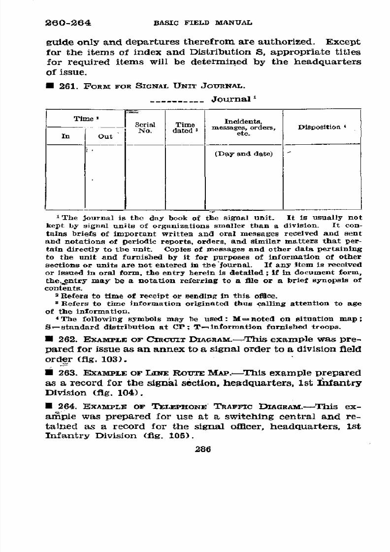
8/16/2019 (1942) FM 24-5 Signal Communication
http://slidepdf.com/reader/full/1942-fm-24-5-signal-communication 290/383
260-264 BASIC
FIELD
MANUAL
guide only and
departures therefrom are
authorized. Except
for
the
items of index and Distribution S, appropriate
titles
for required items
will
be determined by
the headquarters
of issue.
* 261. FORM
FOR
SIGNAL
UNIT
JOURNAL.
-........
-Journal
Time,
____Serial Time
Incidents,
.t..No. datedi
messages, orders, Disposition
'
In Out
(Day
and date)
'The
Journal is the day book of
the
signal unit. It is usually
not
kept
by
signal
units
of
organizations
smaller
than
a
division.
It
con-
tains briefs of important written
and oral
messages received and sent
and notations of periodic reports,
orders,
and similar matters that per-
tain
directly
to the unit.
Copies
of
messages
and
other
data pertaining
to
the
unit and furnished by it
for
purposes
of information of other
sections or
units
are not
entered in the
Journal. If any
item
is received
or
issued
in
oral
form, the entry
herein
is
detailed; if in document
form,
the,entry
may be
a notation
referring
to
a file or a
brief
synopsis
of
contents.
2Refers to
time
of receipt or
sending in this
office.
'
Refers to time
information originated
thus
calling
attention
to age
of the
information.
'The following
symbols
may
be
used: M=noted
on
situation
map;
S=standard
distribution at CP;
T=information
furnished troops.
·
262. EXAMPLE OF
CIRCUiT
DIAGRAM.-This
example was pre-
pared
for issue as an annex
to
a signal order
to
a
division field
order (fig. 103).
*
263.
EXAMPLE
OF
LNE
ROUTE
MAP.-This
example
prepared
as
a record
for
the signal
séction,
headquarters,
lst Infantry
Division (fig.
104).
E 264. EXAMPLE
OF
TELEPHONE TRAFFIC DIAGRAM.-This ex-
amiple was prepared for use at
a switching central and re-
tained
as a record for
the
signal officer, headquarters, 1st
Infantry Division
(fig. 105).
286
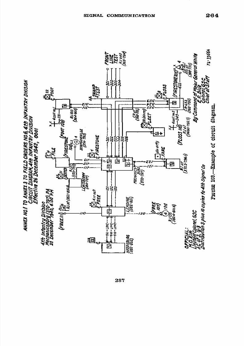
8/16/2019 (1942) FM 24-5 Signal Communication
http://slidepdf.com/reader/full/1942-fm-24-5-signal-communication 291/383
SIGNAL
COMMUNICATION
264
g T
Ilt
,.4
.
s 1 . ' 'W/e
Itt
l
j
I
ItS
3
28
,,
287
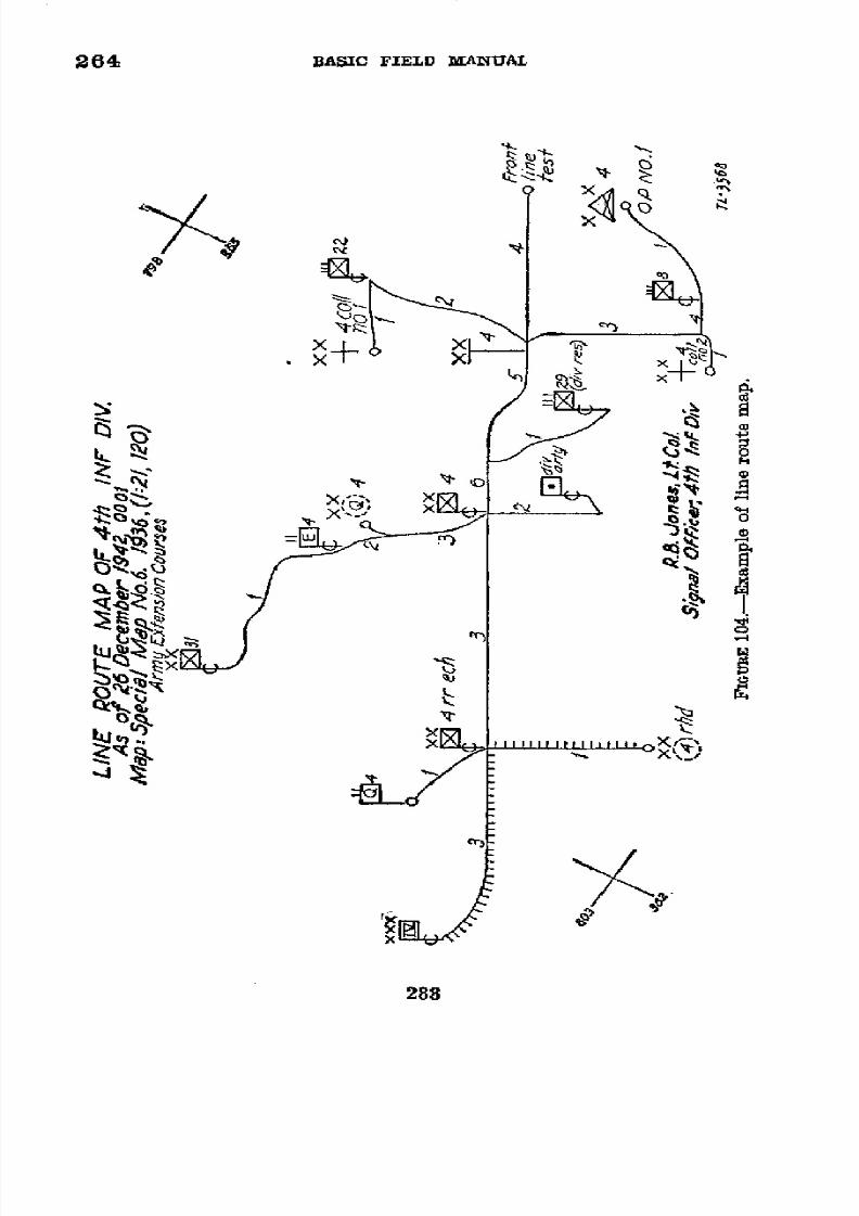
8/16/2019 (1942) FM 24-5 Signal Communication
http://slidepdf.com/reader/full/1942-fm-24-5-signal-communication 292/383
264
BASIC
FIELD
MANUAI
r
x
+y
.
xz
288
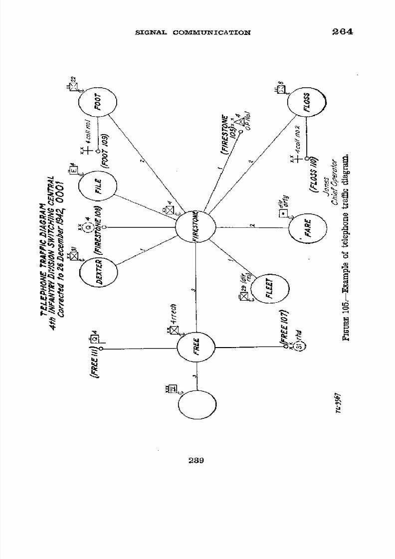
8/16/2019 (1942) FM 24-5 Signal Communication
http://slidepdf.com/reader/full/1942-fm-24-5-signal-communication 293/383
SIGNAL
COMMUNICATION
264
b
X
289
~~~~
1-
tbo
~
~
~
jI~~~~o
o
s
a~~~~28

8/16/2019 (1942) FM 24-5 Signal Communication
http://slidepdf.com/reader/full/1942-fm-24-5-signal-communication 294/383
265
BASIC
FIELD
MANUAL
U 265. EXAMPLES
OF SIGNAL
OPERATION
INSTRUCTIONS
FOR
AN
INFANTRY
DIVISION.-These
examples
are
intended
for
use
as
guides
only.
a.
Instruction
page prescribing the
use
of
signal operation
instructions.
RESTRICTED*
SIGNAL OPERATION
INSTRUCTIONS
4th Infantry
Division
NEW CUMBERLAND,
PA.
24
April
1942,
0900
1. The
signal
operation
instructions prescribed
in Index
No.
1-2 are
issued
for use
in the
4th Infantry Division
effective 0001, 25 April
1942.
Additional
items of signal op-
eration
instructions,
items to
be
issued
at
a later
date,
and
items listed in Index
No.
1-2
which are
to be
changed
will be
issued to
units as prescribed in
distribution S No. 2-1 and
will be accompanied
by a
new index
to
signal
operation in-
structions.
Each
new issue
of
an
item
of
signal
operation
instructions will bear an
authentication.
2.
Except
for
such
extracts
as
may
be
required,
items
of
this
signal
operation instructions
will not be taken
forward
of the
command posts
of front
line
battalions.
3.
Loss
or information
of compromise of
any
item
of this
signal
operation instructions
will
be immediately
reported
to
the
division
signal
officer.
BY
COMMAND
OF
MAJOR
GENERAL
WHITE:
ERNEST R. BLUE,
Colonel,
General
Staff
Corps,
Chief
of Staff.
OFFICIAL:
/s/ MARVIN O. ELM
Marvin
O. Elm,
Lieutenant
Colonel,
General Staff Corps,
Assistant
Chief
of
Staff,
G-3.
DISTRIBUTION:
All units
receiving
items
of
signal
operation
instructions.
RESTRIC:ED
*Classifications
used in
this and
other examples
of signal opera-
tion
instructions
which
follow are
examples
only
and
do not
neces-
sarily
mean
that
those
Instructions
should
be
so
classified.
290

8/16/2019 (1942) FM 24-5 Signal Communication
http://slidepdf.com/reader/full/1942-fm-24-5-signal-communication 295/383
SIGNAL
COMMUNICATION
265
b.
Example
of
index to
signal
operation
instructions.
RESTRICTED
SIGNAL OPERATION
INSTRUCTIONS
INDEX TO
SIGNAL
OPERATION
INSTRUCTIONS
NO.
1-2
4th Infantry
Division
NEW
CUMBERLAND,
PA .
24
April
1942, 0900
Effective
25
April 1942,
0001
Item
Serial
Remarks
No.
I
GENERAL:
Index
to signal
operation
instructions
1-2
Supersedes
No.
1-1.
Distribution
S
.......................
2-1
Index to regulations
and orders on
signal 3-1 To
be issued.
communication.
CODES AND
CIPHER
KEYS:
Supplement to
AGL
T-1-----------.......
4-2
Supersedes
No. 4-1.
Supplement
to
DFO
T-1----------------
15-2
Supersedes No.
5-1.
Authenticator
codoe-------------------------
6-1
Supplement
to
FaO-
_-.. ...........-1
Cipher keys
.-----------------------------
-1
For Oipher
Device
M-94
and
Converter
M-209.
Panel
identification
code
-------------------
9-1
Map
identification
code -..
.
....
0-1
Number and
map
coordinate
code
11-1 Issued
by Corps.
Pyrotechni¡
code
---------------------------
12-1
Issued by Corps.
RADIO COMMUNIOATION:
Radio
frequencies
.------------------
13-1
Radio
call
signs .-...........
14-1
WIRE
COMMUNICATION:
Telephone
directory
-------------------------
15-1
Wire
tagging
code
-1.....-.-. .... 6-1
MISCELLANEOUS:
Daylight
chart and
moon
phase
17-1
Issued
by Corps.
Prearranged
message
cede
------------------
18-1
Issued
by
Corps.
1
First
number
is associated
with the designation
of
the
item;
second is the
serial
issue
of that
item.
RESTRICTED
291
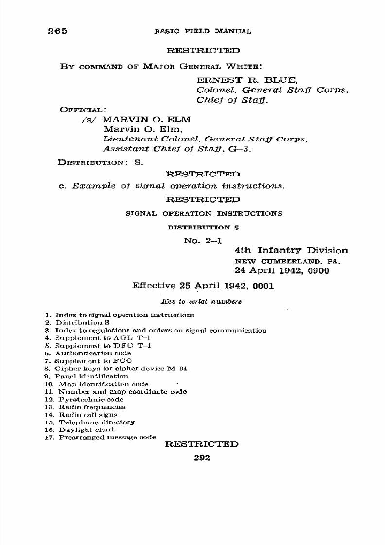
8/16/2019 (1942) FM 24-5 Signal Communication
http://slidepdf.com/reader/full/1942-fm-24-5-signal-communication 296/383
265
BASIC FIELD
MANUAL
RESTRICTED
BY
COMMVAND
OF MAJOR GENERAL WHITE:
ERNEST R. BLUE,
Colonel, General Staff Corps,
Chief
of Staff.
OFFICIAL:
/S/ MARVIN O. ELM
Marvin O.
Elm,
Lieutenant Colonel, General Staff Corps,
Assistant
Chiei
of
Staff,
G-3.
DISTRIBUTION: S.
RESTRICTED
c. Example
of signal operation instructions.
RESTRICTED
SIGNAL
OPERATION INSTRUCTIONS
DISTRIBUTION
S
No. 2-1
4th
Infantry
Division
NEW
CUMBERLAND,
PA.
24 April
1942, 0900
Effective 25 April
1942, 0001
Key
to
serial nunmbers
1. Index
to signal operation
instructions
2. Distribution S
3. Index to regulations and orders on signal communication
4.
Supplement
to
AGL T-1
5. Supplement to DFC T-1
6.
Authentication
code
7.
Supplement to
FCC
8.
Cipher
keys
for
cipher
device M-94
9. Panel identification
10.
Map identification code
11. Number and
map
coordinate code
12. Pyrotechnic code
13. Radio frequencies
14. Radio
call
signs
15. Telephone directory
16. Daylight chart
17. Prearranged message
code
RESTRICTED
292

8/16/2019 (1942) FM 24-5 Signal Communication
http://slidepdf.com/reader/full/1942-fm-24-5-signal-communication 297/383
SIGNAL COMMUNICATION
265
RESTRICTED
Organizations
1
2
3 4 5 7 8
9 1011121314 15
1
17
Staff
Officers
Div
Hq-2
22-2
2-
2 2
Division
Signal
Officer-. . 10
10
10 10 110
1010
10
10
10 10 10 10 0
10
4th Signal
Company
-.
.
.5
5 5 5 5
5 5
5
5 5 5 20
10 20
8th Inf Hq &
Hq Co ----
4
44
4
4
Ea Inf Bn-Total
----------------
44
6
22d
Inf
Hq &
Hq COo4
---.......
44
4
4
Ea Inf Bn-Total
-
4.. ...........4
4
6
29th
Inf
Hq
&
Hq Co
.-
4..
.
4 Numbers
represent
such
4
Ea
Inf
Bn-Total.-4..
---------- 44
quantities
as
are necessary 4
6
Hq
Division Artillery
.- 1.........
for distribution.
(It
is
in-
5
29th
FA
Bn,
105-mm
-4-----------
44
tended to
show
that
num-
4 4
42d
FA
Bn, 105-mm -
.
.... 4
4
bers
throughout
the
table
4 4
44th
FA
Bn,
105-mm
4 44 will
be
inserted
in
the quan- 4
4
20th
FA
Bn,
155-mm
4
4.
tities necessary;
those
4 4
4th
Engr
Bn
.- .................
44 shown
are
not fixed).
4 4
4th Med Bn -1----------------------
1
1
4th
QM
Bn
-1-------.-.
11
1-
4th Rcn Troop
-------------
-
4
4
4
12
IV Corps-4-------------------------
4
4
4
31st Infantry
Division4
4 4 4 4 4 4
4 4 4 4 4
4
43d Infantry
Division-
4
4
4_ 4
4 4 4 4 4 4
4
4 4 4
4
Diary
…--------
1 1 1
1 1
1 1 1
1 1 1
Total
-
8
8E83 76
37 60
48
64 81
83 83 81 44 44 104 90 112
BY COMMAND
OF
MAJOR
GENERAL WHITE:
ERNEST
R.
BLUE,
Colonel, General
Staff Corps,
Chief
of
Staff.
OFFICIAL:
/s/
MARVIN
O. ELM
Marvin O. Elm,
Lieutenant Colonel,
General Staff
Corps,
Assistant
Chief
of
Staff, G-3.
DISTRIBUTION:
S.
RESTRICTED
293

8/16/2019 (1942) FM 24-5 Signal Communication
http://slidepdf.com/reader/full/1942-fm-24-5-signal-communication 298/383

8/16/2019 (1942) FM 24-5 Signal Communication
http://slidepdf.com/reader/full/1942-fm-24-5-signal-communication 299/383
SIGNAL
COMMUNICATION 265
RESTRICTED
2.
Map
coordinates
appearing in
messages
encoding
in the
Air-Ground
Liaison
Code will
be
encoded
in
the
map
coordi-
nate code
listed in
the
current Index to Signal Operation
Instructions
of this
division.
BY
COMMAND
OF
MAJOR GENERAL
WHITE:
ERNEST
R.
BLUE,
Colonel,
GeneralStaff
Corps,
Chief
of
Staff.
OFFICIAL:
/s/
MARVIN O.
ELM
Marvin
O. Elm,
Lieutenant Colonel, General
Staff
Corps,
Assistant Chief
of Staff, G-3.
DISTRIBUTION: S.
RESTRICTED
e.
Example
of
signal
operation
instructions
supplement
to
DFC T-1.
RESTRICTED
SIGNAL
OPERATION
INSTRUCTIONS
SUPPLEMENT TO DFC T-1
NO. 5-2
4th
Infantry Division
NEW
CUIMBERLAND,
PA.
24 April
1942, 0900
Effective 25 April
1942, 0001
ENCODING
Meaning
Code
group
Meaning
Code
group
ABBOTTSTOWN
---
EKZC
1224 BLACK
ROCK-__--EWEA
1429
BACHMAN
MILLS_-
ETSZ
1392
BOILING SPRINGS_
EWIE
1433
BAIR -----------
EVGO
1406
BOWMANSVILLE
_- EWWS
1446
BALTIMORE
------
EVNW 1413
BRICKLYN--___--
EXIS
1458
BALTIMO
R
E
CARLISLE
JUNC-
&
HANOVER
RD__
WIIO
5083
TION---__---_.
EXJT
1459
BECKLEYSVILLE--__ EVRZ
1416 CRANBERRY
___-
-
EXWF 1471
BIXILER---------
EWBX 1426 DALLASTOWN----
EXYH
1473
RESTRICTED
295

8/16/2019 (1942) FM 24-5 Signal Communication
http://slidepdf.com/reader/full/1942-fm-24-5-signal-communication 300/383
265 BASIC
FIELD
MANUAL
RESTRICTED
Meaning
Code group Meaning
Code
group
DILLSBURG-__-__-
FALW
1511
HAMPSTEAD------
ARGO
0356
DUG
HILL
RIDGE__ WUGF 5131 HOFFMANVILLE___ ARPY 0365
EBBVALE
--- _-- FAMX 1512 KEENER---- - - - - - ARYG
0373
EKLO ----------
FEUG 1544 KINGSDALE-_____ ASDZ 0378
FISCAL__ _______. FIXL
1572
LINEBORO__ ____. ASGC 0381
FREELAND_______.. FIYM
1573
LOGANVILLE
_____ ASVR 0395
GLADFELTERS_____ FOOG 1589
MANCHESTER____
ATPZ
0415
GLEN ROCK ______
FORI 1591
MAPLE GROVE___.. WUML 5137
GUILDENS_______-
FOTK
1593
MECHANICSBURG_ ATRA
0416
GUNPOWDER FALLS
CREEK ________ APWR
0346
DECODING
Code
group
Meaning Code group
Meaning
APWR 0346 Ga N P o W D E
EWWS 1446 BOWMANSVILLE
FALLS CREEK
AGRO 0356 HAMPSTEAD EXIS 1458 BRICKLYN
ARPY
0365 HOFFMANVILLE EXJT
1459
CARLISLE
JUNC-
TION
ARYG 0373 KEENER EXWF 1471 CRANBERRY
ASOZ 0378 KINGSDALE EXYH 1473 DALLASTOWN
ASGC 0381 LINEBORO
FALW 1511
DILLSBURG
ASVR
0395 LOGANVILLE FAMX
1512
EBBVALE
ATPZ
0415
MANCHESTER
FEUG,
1544
EKLO
ATRA 0416
MECHANICSBURG
FIXL
1572
FISCAL
EKZC 1224 ABBOTTSTOWN FIYM
1573 FREELAND
ETSZ 1392
BACHMAN
MILLS
FOOG
1589
GLADFELTERS
EVGO
1406 BAIR
FORI
1591
GLEN
ROCK
EVNW
1413 BALTIMORE
FOTK
1593 GULDENS
EVRZ
1416 BECKLEYSVILLE
WIIO 5083 BALTIMORE
&
EWBX 1426
BIXILER
HANOVER RD.
EWEA
1429
BLACK ROCK
WUGF
EWIE 1433
BOILING SPRINGS
WUML
BY COMMAND OF
MAJOR
GENERAL
WHITE:
ERNEST R.
BLUE,
Colonel, GeneralStaff Corps,
Chief of Staff.
RESTRICTED
296
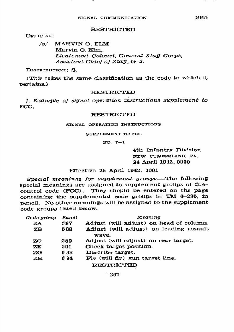
8/16/2019 (1942) FM 24-5 Signal Communication
http://slidepdf.com/reader/full/1942-fm-24-5-signal-communication 301/383
SIGNAL
COMMUNICATION
265
RESTRICTED
OFFICIAL:
/s/
MARVIN
O.
ELM
Marvin O.
Elm,
Lieutenant
Colonel, General
Staff
Corps,
Assistant
Chief
of
Staff,
G-3.
DISTRIBUTON:
S.
(This
takes
the
same
classification as
the code
to
which
it
pertains.)
RESTRICTED
f.
Example
of
signal
operation
instructions
supplement
to
FCC.
RESTRICTED
SIGNAL
OPERATION
INSTRUCTIONS
SUPPLEMENT
TO
FC C
NO.
7-1
4th
Infantry
Division
NEW
CUMBERLAND,
PA.
24 April 1942,
0900
Effective
25
April
1942,
0001
Special
meanings for
supplement
groups.-The
following
special
meanings
are
assigned
to supplement
groups
of
fire-
control
code
(FCC).
They
should
be entered
on
the
page
containing
the
supplemental
code
groups
in
TM
6-230,
in
pencil.
No other
meanings
will
be assigned
to the
supplement
code
groups
listed
below.
Code
group
Panel
Meaning
ZA
087
Adjust
(will
adjust)
on
head
of
column.
ZB
088
Adjust
(will
adjust)
on
leading
assault
wave.
ZC
089
Adjust
(will
adjust)
on
rear
target.
ZE
091
Check
target
position.
ZG
093
Describe
target.
ZH
0 94
Fly
(will
fly) gun
target
line.
RESTRICTED
297
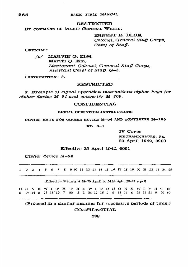
8/16/2019 (1942) FM 24-5 Signal Communication
http://slidepdf.com/reader/full/1942-fm-24-5-signal-communication 302/383
265
BASIC
FIELD
MANUAL
RESTRICTED
BY
COMMAND
OF
MAJOR
GENERAL
WHITE:
ERNEST
R.
BLUE
Colonel,
General
Staff
Corps,
Chief
of
Staff.
OFFICIAL:
/s/ MARVIN
O. ELM
Marvin
O. Elm,
Lieutenant
Colonel,
General
Staff Corps,
Assistant
Chief
of
Staff,
G-3.
DISTRIBUTION: S.
RESTRICTED
g. Example
of
signal
operation instructions
cipher
keys for
cipher
device
M-94
and
converter M-209.
CONFIDENTIAL
SIGNAL
OPERATION INSTRUCTIONS
CIPHER
KEYS FOR
CIPHER DEVICE
M-94 AND
CONVERTER
M-209
NO.
8-1
IV
Corps
MECHANICSBURG,
PA.
23
April
1942,
0900
Effective
25
April
1942,
0001
Cipher
device
M-94
1
2 3 4 5
6 7 8
9 10
11 12 13
14 15 16
17
18 19 20 21
22 23 24
26
Effective
Midnight 24-25
April to
Midnight
28-29 April
G
0 N
E
WIT HTE
WIND0NE
WI
TT
H
5
17 14
2
23
1119 7 20
8 3 24 12 15
1
6
18
16
4
25
13
21 9 22 10
(Proceed
in
a similar manner
for
successive periods of time.)
CONFIDENTIAL
298

8/16/2019 (1942) FM 24-5 Signal Communication
http://slidepdf.com/reader/full/1942-fm-24-5-signal-communication 303/383
SIGNAL COMMUNICATION
265
CONFIDENTIAL
Converter
M-209
Position
of
Key
Wheel
Pins
Period of Midnight
24-25
April to Midnight
28-29 April
No. 1 No. 2 No. 3 No. 4 No. 5 No.
6
(26) (25)
(23) (21)
(19)
(17)
A- -A A- -A -A A-
B-
-B
B-
-B
B- B-
-0 -C -Ca
-
-o
-c
D- D-
-D -D
D- D-
-E E- -E E- E- -E
-F -F -F F- F-
-F
-G
o-
-
-G
-G -G
H- -H
H- H-
H-
H-
I- -I
-I *
I- I-
-I
-J 3- J-
-J
-J
-J
K-
K- -K -K
-K
K-
-L
L-
L- -L -L
-L
M- -M M- M- M-
-M
N-
-N
N-
N-
N- N-
-O
0- -o
-o
-o
0-
-P
-p - P- Pp -P
-Q -Q
- -Q -Q
Q-
-R R- R- -R -R
S- S- S-
S- S-
T- -T T-
T-
-U
U-
U-
U-
V- -V
V-
W- X-
X-
-X
-Y
-Y
-Z
-Z
(Proceed
in a
similar
manner for
successive
periods of
time.)
Position
of Drum Bar Lugs
Period of
Midnight
2"425 April
to Midnight
April
30-May 1
CONFIDENTIAL
299
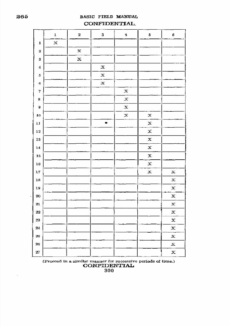
8/16/2019 (1942) FM 24-5 Signal Communication
http://slidepdf.com/reader/full/1942-fm-24-5-signal-communication 304/383
265
BASIC FIELD MANUAL
CONFIDENTIAL.
1 2
3 4
5
6
1
X
2
X
4
X
5
X
6 X
7
X
8
X
9
X
o1
X
X
11
·
X
12
X
13
X
14
X
15
X
16 X
17
X
X
18
X
19 X
20
X
21
X
22
X
23
X
24
X
25
X
26
X
27 x
(Proceed in a similar manner for successive periods
of
time.)
CONFlDENTIAL
300
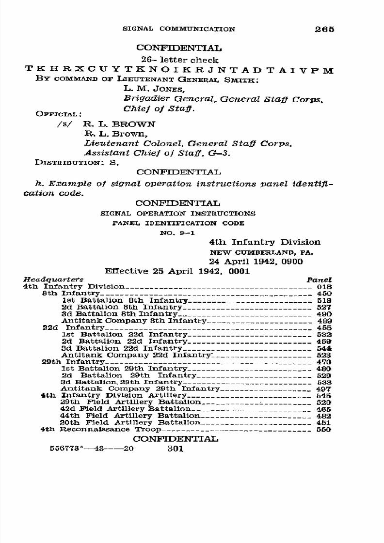
8/16/2019 (1942) FM 24-5 Signal Communication
http://slidepdf.com/reader/full/1942-fm-24-5-signal-communication 305/383

8/16/2019 (1942) FM 24-5 Signal Communication
http://slidepdf.com/reader/full/1942-fm-24-5-signal-communication 306/383
266
BASIC
FIELD
MANUAL
CONFIDENTIAL
BY
COMMAND OF
MAJOR
GENERAL
WHITE:
ERNEST
R. BLUE,
Colonel,
General
Staff
Corps,
Chief
of
Staff.
OFFICIAL:
/s/
MARVIN
O. ELM
Marvin
O.
Elm,
Lieutenant
Colonel,
General Staff
Corps,
Assistant
Chief oj
Staff, G-3.
DISTRIBUTION:
S.
CONFIDENTIAL
i. Example of
signal
operation instructions
map
identifi-
cation
code.
CONFIDENTIAL
SIGNAL OPERATION INSTRUCTIONS
MAP
IDENTIFICATION
CODE
NO. 10-1
4th
Infantry Division
NEW
CUMBERLAND,
PA .
24 April 1942,
0900
Effective 25
April
1942, 0001
Map
name
Identification
Code groups
MOs~p nam~
~ April
25-30 May
1-6
Abbotstown
sheet, 1/21, 120
.-.....
.
TQ
LV
Antietam
quadrangle,
1/62, 500 -----------------------
PZ
EP
Arendtsville
sheet, 1/21, 120
-................
YN
CL
Baltimore
quadrangle, 1/62,
500-.-.-.-.
--
--
QX MK
Belair
quadrangle,
1/62,
500
.......-. .
AI
EW
Bonneauville
sheet,
1/21, 120
-...
- --
TM
CA
Carlisle
quadrangle, 1/62,
500 .-..
........
PM
CU
CONFIDENTIAL
302

8/16/2019 (1942) FM 24-5 Signal Communication
http://slidepdf.com/reader/full/1942-fm-24-5-signal-communication 307/383
SIGNAL COMMUNICATION
265
CONFIDENTIAL
Map
name
Identification
Code groups
April
25-30
May
1-6
Chambersburg
quadrangle, 1/62, 500 .......
ZS
QB
Ellicott quadrangle, 1/62, 500
-....
V... ...B CP
Emmitsburg
quadrangle,
1/62, 500 -------------------
VN IH
Emmitsburg
sheet, 1/21, 120 .----------------
ClH
ZL
Fairfield
quadrangle,
1/62, 500
.----------------------
UA
OV
Fairfield sheet,
1/21,
120
LR
HO
General
map,
Gettysburg
(1925)
1/312,
500 .------
WE AY
Gettysburg
quadrangle, 1/62,
500
.-..
ZB
YK
Gettysburg
sheet,
1/21,
120
..-.....
- -
WO
UK
Hagerstown
quadrangle, 1/62, 500
.-.
...........
YA YG
Hanover quadrangle,
1/62, 500 -.....-
-
PR
GT
Hanover
sheet, 1/21,
120
.-.... - -
TX
LA
Harrisburg
quadrangle,
1/62, 500
.-..
...
....S ZT
Hunterstown
sheet,
1/21,120
.-.----------------------
AO YZ
Ijamsville quadrangle,
1/62, 500 ....
ZN
OQ
Kingsdale
sheet, 1/21, 120 .-.......
LU
HD
Knowlyn
sheet,
1/21, 120
.-...
KY
GR
Mercersburg quadrangle,
1/62,
500 ...-......
BI
WJ
Middletown
quadrangle,
1/62,
500 ...---------------- WV
ZL
Mount
Airy
quadrangle,
1/62,
500 ..-
................
NM
GD
New
Cumberland
quadrangle,
1/62, 500 .-..
BG
AZ
Newman
sheet, 1/21,
120
-...........
...... XT YT
CONFIDENTIAL
303

8/16/2019 (1942) FM 24-5 Signal Communication
http://slidepdf.com/reader/full/1942-fm-24-5-signal-communication 308/383
265
BASIC
FIELD
MANUAL
CONFIDENTIAL
BY
COMMAND
OF
MAJOR
GENERAL
WHITE:
ERNEST
R.
BLUE,
Colonel, General
Staff
Corps,
Chief
of
Staff.
OFFICIAL:
/s/
MARVIN
O.
ELM
Marvin
O. Elm,
Lieutenant
Colonel,
General
Staff
Corps,
Assistant
Chief
of
Staff,
G-3.
CONFIDENTIAL
j.
Example
of
signal
operation
instructions
number
and
map
coordinate
code.-This
system
can
be used
to indicate
grid,
polar,
or
thrust line
coordinates.
CONFIDENTIAL
SIGNAL
OPERATION
INSTRUCTIONS
NUMBER
AND
MAP
COORDINATE
CODE
NO. 11-1
IV
Corps
MECHANICSBURG,
PA.
23 April
1942,
0900
Effective
24
April
1942,
0001
1.
Purpose anc
construction
of
the
chart.---a.
This number
chart
can
be used
for
indicating
numbers
of any
type,
includ-
ing map
coordinates
expressed
in
any
of
the three
generally
accepted
systems,
namely,
gridded
quadrangles
of
the U.
S.
Geological
Survey,
polar
coordinates,
or point
of
origin-
extension
point
coordinates.
b.
The
chart
has -been
constructed
in
four
sections
num-
bered
I,
II,
III,
and
IV
so
that
by
combining
properly
the
groups
from
the
various
sections
any
desired
number
can be
expressed.
Sections
I and
II
are
intended
to be
used together
to
express
any
number
under
100
to
the nearest
tenth
by
means
of
a single
three-letter
group.
Sections
m and
IV
are intended
to
be
used together
to
express
round
numbers
above
100. In
line
A
the
numbers
from
100 to
995 can
be
CONFIDENTIAL
304
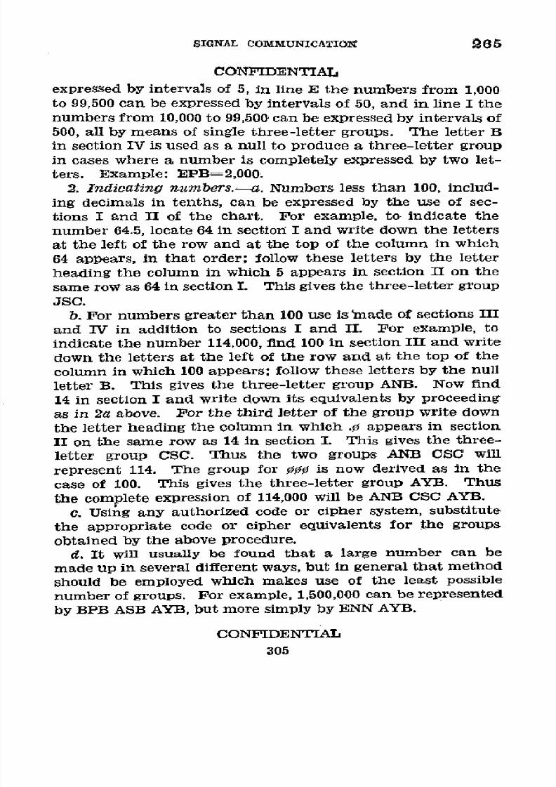
8/16/2019 (1942) FM 24-5 Signal Communication
http://slidepdf.com/reader/full/1942-fm-24-5-signal-communication 309/383
SIGNAL
COMMUNICATION
265
CONFIDENTIAL
expressed
by
intervals
of
5, in
line
E
the
numbers
from
1,000
to
99,500
can
be
expressed
by
intervals
of
50,
and
in
line
I
the
numbers
from
10,000
to 99,500
can
be
expressed
by intervals
of
500,
all by
means
of single
three-letter
groups.
The
letter
B
in
section
IV is
used as
a
null
to produce
a three-letter
group
in
cases
where a
number
is
completely
expressed
by two
let-
ters. Example:
EPB=2,000.
2. Indicating
numbers.-a.
Numbers
less than
100, includ-
ing
decimals
in
tenths,
can
be expressed
by the
use
of sec-
tions
I
and
II
of
the
chart.
For
example,
to
indicate
the
number
64.5,
locate
64
in
section
I and
write
down
the letters
at
the left
of the
row and
at
the
top of
the
column
in
which
64
appears,
in that
order;
follow
these
letters
by the
letter
heading
the
column
in which
5 appears
in
section
II
on
the
same
row as 64
in section
I.
This
gives
the three-letter
group
JSC.
b.
Por numbers
greater
than 100
use
is
made
of
sections
III
and IV
in
addition
to
sections
I and
II.
For example,
to
indicate
the
number
114,000,
find
100 in
section
III
and
write
down
the
letters
at the
left
of the
row
and
at the
top
of the
column
in
which
100 appears;
follow
these
letters
by the null
letter B.
This
gives
the three-letter
group
ANB.
Now
find
14
in section
I and write
down
its
equivalents
by
proceeding
as in
2a
above. For
the third
letter
of
the
group
write
down
the
letter
heading
the
column
in
which .0 appears
in
section
II
on the
same
row as
14
in
section
I. This
gives
the three-
letter
group
CSC.
Thus
the
two
groups
ANB
CSC
will
represent
114.
The
group
for 000
is
now
derived
as
in
the
case
of 100.
This
gives
the
three-letter
group
AYB.
Thus
the
complete
expression
of
114,000
will
be ANB
CSC AYB.
e.
Using
any authorized
code
or cipher
system,
substitute
the
appropriate
code
or
cipher
equivalents
for
the
groups
obtained
by
the
above
procedure.
d.
It will usually
be
found
that
a
large
number
can be
made
up
in several
different
ways,
but
in general
that
method
should
be
employed
which
makes use
of
the
least
possible
number
of groups.
For
example,
1,500,000
can
be
represented
by
BPB
ASB
AYB,
but
more
simply
by
ENN
AYB.
CONFIDENTIAL
305

8/16/2019 (1942) FM 24-5 Signal Communication
http://slidepdf.com/reader/full/1942-fm-24-5-signal-communication 310/383
265 BASIC
FIELD
MANUAL
CONFIDENTIAL
3. Indicating
grid
coordinates.-a.
The method
of
using
the
number
chart
to
indicate
grid
coordinates
applicable
to
a
gridded map can best be explained by
means
of
an
example.
Assume the
coordinates
to be
332.8-749.5.
Locate the number
300
in
section
III and write
down
the
letters at
the left of
the row and at
the
head of the column in which 300 appears,
in
that order,
plus the
null
letter
B, as:
AQB. Then
find
32
in section I and write down
the letters at
the
left of
the row
and
at
the top of the column in which
32
appears,
in that
order;
follow
these
letters
by
the letter
heading
the
column
in
which
8
appears in section II on
the
same
row as
32 in
section I. This
gives
the three-letter group
FQC. Thus
332.8 is expressed by the two groups
AQB
FQC.
b. For 749.5, proceeding as
in
3a above,
write AVB
GYM.
c. Using any
authorized
code or cipher system, substitute
for
AQB
FQC
AVB
GYM
the
code
or cipher equivalents of
those
twelve
letters.
4. Indicating polar
coordinates.-a.
Polar
coordinates
are
commonly given in this
order:
(1) magnetic azimuth
in
de-
grees, (2) reference
point,
(3) distance in
miles,
or yards.
To indicate the
polar coordinates
105
°
C
12,
locate the
num-
ber 100 in section III
and
write
down the letters
at the left
of the row
and
at the top of the column in which
100
appears;
follow
these
letters by
the
letter heading
the
column
in which
05
appears
in
section
IV.
This
gives
the
three-letter
group
ANC.
b.
Write
down
the reference point letter C.
c. Find 12 in section I and write
down the
letters at
the
left of the
row
and at the top of
the column
in which
12
appears; follow these
letters by the
letter
heading
the column
in
which 0
appears in
section
II on the
same
line' as 12
in
section
I. This gives the three-letter group CQC.
d.
Using
any
authorized
code
or cipher
system,
substitute
for
ANC
C. CQC the code or cipher equivalents of those seven
letters.
5.
Indicatingpoint
of
origin-extensionpoint coordinates.-
a. Coordinates
in this
system
are commonly
given in this
order:
(1) distance
in
miles (or
yards) from
point of origin,
(2) left or right, (3) distance
to left or right in miles
(or
CONFIDENTIAL
306
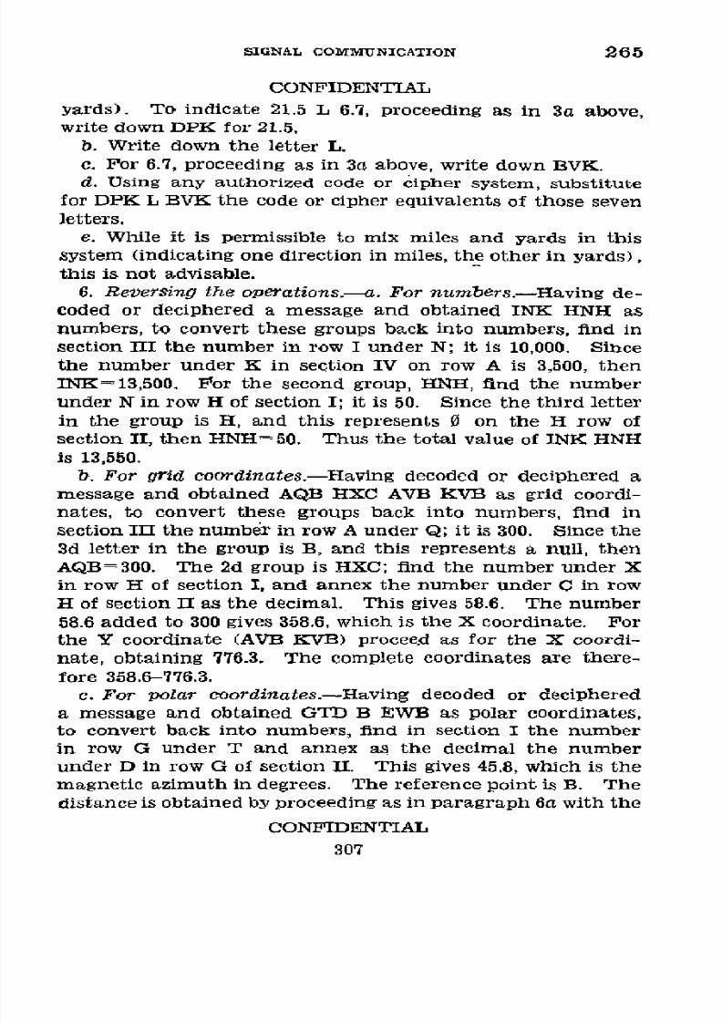
8/16/2019 (1942) FM 24-5 Signal Communication
http://slidepdf.com/reader/full/1942-fm-24-5-signal-communication 311/383
SIGNAL
COMMUNICATION
265
CONFIDENTIAL
yards).
To
indicate
21.5
L 6.7, proceeding as in 3a above,
write down DPK
for
21.5.
b.
Write down
the letter L.
c.
For 6.7, proceeding
as
in 3a above, write
down BVK.
d.
Using
any authorized code
or
cipher
system, substitute
for DPK L
BVK
the code
or
cipher equivalents
of
those seven
letters.
e.
While
it is
permissible
to mix miles
and yards
in this
system (indicating one direction in miles, the other in yards),
this
is
not
advisable.
6.
Reversing
the operations.-a.
For
numbers.-Having
de-
coded or deciphered
a
message and obtained INK HNH
as
numbers, to convert
these groups
back
into
numbers, find
in
section
III
the number
in
row
I under N; it is 10,000.
Since
the number
under
K
in section IV on
row
A is
3,500,
then
INK=13,500.
For the second
group,
HNH,
find
the
number
under N in row H
of
section I; it is 50.
Since
the third letter
in
the
group
is
H,
and
this
represents 0
on
the
H row
of
section II,
then
HNH=50. Thus the
total
value of INK HNH
is 13,550.
b.
For
grid
coordinates.-Havingdecoded
or deciphered
a
message and
obtained AQB
HXC
AVB KVB as grid coordi-
nates,
to
convert these
groups
back
into numbers, find in
section III the number
in
row
A under
Q;
it
is
300.
Since the
3d
letter
in
the
group is
B,
and
this
represents
a
null,
then
AQB=300. The 2d group is HXC; find the
number
under X
in
row H of
section I,
and
annex
the
number
under
C
in row
H of section
II
as the decimal. This
gives
58.6. The number
58.6
added to
300
gives 358.6, which is
the X
coordinate.
For
the Y
coordinate (AVB
KVB)
procee.d
as for the X coordi-
nate, obtaining 776.3.
The
complete
coordinates are
there-
fore 358.6-776.3.
c.
For polar
coordinates.-Having
decoded
or
deciphered
a
message and
obtained
GTD B EWB as
polar coordinates,
to convert back
into
numbers,
find in
section I
the number
in
row G
under T
and
annex as the decimal
the
number
under D in row
G
of section II.
This
gives
45.8,
which is the
magnetic
azimuth
in
degrees. The
reference
point is
B.
The
distance
is obtained
by
proceeding as in paragraph
6a
with
the
CONFIDENTIAL
307
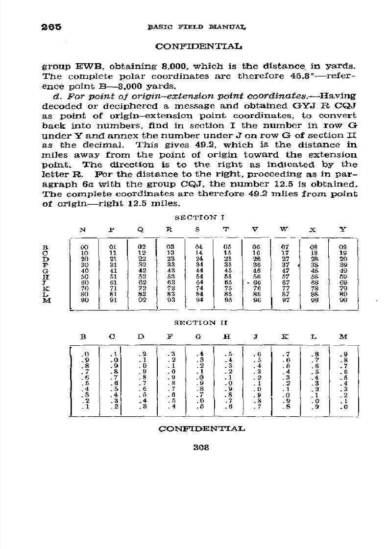
8/16/2019 (1942) FM 24-5 Signal Communication
http://slidepdf.com/reader/full/1942-fm-24-5-signal-communication 312/383
265
BASIC
FIELD
MANUAL
CONFIDENTIAL
group EWVB,
obtaining
8,000,
which
is the
distance
in
yards.
The
complete
polar
coordinates
are therefore
45.8°-refer
-
ence point
B-8,000
yards.
d. For
point
of
origin-extension
point
coordinates.-Having
decoded
or deciphered
a message and
obtained
GYJ R CQJ
as point
of
origin-extension
point coordinates,
to
convert
back
into
numbers,
find in section
I the
number
in
row G
under Y and annex
the
number
under J on
row G
of
section II
as
the
decimal.
This
gives
49.2,
which is
the
distance
in
miles
away
from
the
point of origin
toward
the extension
point. The
direction
is to
the right as indicated
by the
letter
R.
Por the distance
to
the right,
proceeding as
in
par-
agraph 6a
with
the
group CQJ,
the number
12.5
is obtained.
The
complete coordinates
are therefore
49.2
miles
from
point
of origin-right
12.5
miles.
SECTION
I
N P
Q
R
S
T
V
W
X
Y
B 00 01
02
03
04 05
06 07 08 09
o
10 11
12
13 14
15
16 17 18
19
D
20 21
22 23 24
25 26 27
28
29
F 30 31
32
33
34 35
36
37 38
39
O
40 41
42
43 44
45 46
47
48
49
H 50
51
52
53 54 55
56 57 58 59
J
60
61
62
63 64 65
· 66
67 68
69
K
70
71
72 73
74
75
76 77 78 79
L
80 81
82 83
84
85 86 87
88 89
M
90
91
92
93
94
95 96 97 98
99
SECTION II
B
0
D
F
O H
J K L
M
.0 .1 .2 .3 .4
.5
.6 .7 .8 .9
.9 .0 .1 .2 .3
.4 .5 .6 .7
.8
.8
.9
.0 .1
.2
.3 .4
.5
.6
.7
.7
.8
.9
.0
.1
.2
.3 .4 .5
.6
.6
.7 .8 .9
.0
.1 .2 .3
,4
.5
.5
.6
.7 .8
.9
.0
.1
.2
.3 .4
.4 .5 .6 .7
.8
.9 .0 .1 .2
.3
.3
.4 .5 .6
.7 .8 .9
.0
.1 .2
.2 .3
.4 .5
.6 .7
.6 .9
.0 .1
.1
.2 .3 .4 .5
.6
.7 .8
.9
.0
CONFIDENTIAL
308
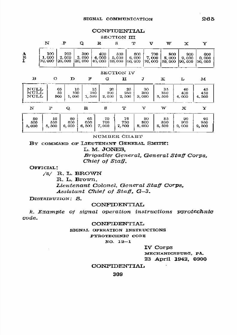
8/16/2019 (1942) FM 24-5 Signal Communication
http://slidepdf.com/reader/full/1942-fm-24-5-signal-communication 313/383
SIGNAL
COMMUNICATION
265
CONFIDENTIAL
SECTION III
N
.P
Q
R
S
T
V
W
X
Y
A 100
200 300 400 500 600
700
800 900 000
E
1 2,00 003, 000 4,000000
000
000 7,00, 000 000 0 000
0, 000 20, 000
30,
000 40,000 50,000
60,
000 70,000 000
000
,000
SECTION IV
B 0 D F O I J 1K
L
M
NULL
05
10 15
20 25
30
35
40
45
NULL 50
100 150 200
200 300 350
400 450
NULL 500 1,000 1,500 2, 000
2,
500 3,000 3, 500
4,000
4, 500
N P Q R S
T V W X Y
.60
i55
60 65 70 75 80 85 90
95
500
50 600 650 750
800 850 900 950
5,000 5,500 6,000 6,
300
7,000
7, 500 8,000 8, 500 9,000
9,
50 0
NUMBER
CHART
BY COMMAND
OF
LIEUTENANT GENERAL
SMITH:
L. M. JONES,
Brigadier General, General
Staff Corps,
Chief
of
Staff.
OFFICIAL:
/s/
R. L. BROWN
R.
L. Brown,
Lieutenant Colonel, GeneralStaff Corps,
Assistant Chief
of
Staff, G-3.
DISTRIBUTION: S.
CONFIDENTIAL
k. Example
of
signal operation
instructions pyrotechnic
code.
CONFIDENTIAL
SIGNAL
OPERATION INSTRUCTIONS
PYROTECHNIC CODE
NO.
12-1
IV Corps
MECHANICSBURG, PA.
23 April 1942, 0900
CONFIDENTIAL
309
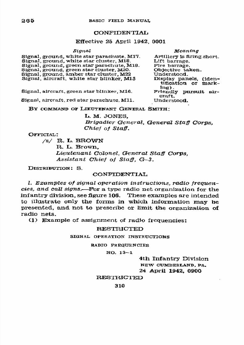
8/16/2019 (1942) FM 24-5 Signal Communication
http://slidepdf.com/reader/full/1942-fm-24-5-signal-communication 314/383
265
BASIC FIELD
MANUAL
CONFIDENTIAL
Effective
25 April 1942,
0001
Signal
Meaning
Signal,
ground, white
star
parachute,
M17.
Artillery
is
firing
short.
Signal, ground, white
star
cluster, M18.
Lift
barrage.
Signal,
ground,
green star parachute,
M19.
Fire barrage.
Signal,
ground,
green
star
cluster,
M20.
Objective taken.
Signal, ground,
amber star
cluster, M22
Understood.
Signal,
aircraft,
white
star
blinker,
M15
Display
panels,
(iden-
tification
or
mark-
ing).
Signal,
aircraft,
green
star
blinker,
M16.
Friendly
pursuit
air-
craft.
Signal,
aircraft, red star
parachute, Mll.
Understood.
BY
COMMAND
OF LIEUTENANT
GENERAL
SMITH:
L. M.
JONES,
Brigadier
General,
General
Staff
Corps,
Chief of Staff.
OFFICIAL:
/s/ R.
L.
BROWN
R.
L.
Brown,
Lieutenant Colonel,
General
Staff Corps,
Assistant
Chief
of Staff,
G-3.
DISTRIBU ION:
S.
CONFIDENTIAL
1.
Examples
of signal
operation instructions,
radio
frequen-
cies,
and
call
signs.-EPor
a type
radio
net
organization for
the
infantry
division,
see figure
106.
These examples
are
intended
to
illustrate
only
the forms
in
which
information
may
be
presented,
and
not
to prescribe
or limit the
organization of
radio
nets.
(1)
Example
of
assignment
of
radio
frequencies:
RESTRICTED
SIGNAL OPERATION
INSTRUCTIONS
RADIO FREQUENCIES
NO. 13-1
4th
Infantry Division
NEW
CUMBERLAND,
PA.
24
April 1942,
0900
RESTRICTED
310

8/16/2019 (1942) FM 24-5 Signal Communication
http://slidepdf.com/reader/full/1942-fm-24-5-signal-communication 315/383
SIGNAL COMMUNICATION
265
RESTRICTED
Effective
25
April
1942,
0001
Designation
m
E
CC
CC
r~
W-2520
A-
2980
3860
3880 3960
4120
4340
4820
X-220
620 3060
Z-2820
Net
frequency
W-250
X-
]3-
710
3100
- 2950
3840 3890
3920
4330
4100 4860
£
1710 3100
Z-2840
UNIT
IV
Corps
--
-
X ---
-----
---------
----
----------
----
-----
4th
Inf Div
---
X X
X
.......
X
-------
X
X
31st
Inf
Div-
_
X -----
---- ----- -----
----- -----
---------- ----
-----
43d
Inf
Div .----
X
Sth
Inf-20-------------.....
X
X
X .
.......................-----
X
ist
Bn
............-
2-
----------------
2d
Bn
-
3d Bn-
...........................
Vehicle
Set No. 1
------.-----....
X
22d Inf
-20----------.
X X
--
X ------
X
1st
Bn -----
.
-----
-----
-----
---------
X
- -
2d
Bn
-------------.-----
-----
-----
----- X
-
-----....................
3d
Bn................................
X
...............................
Vehicle
Set No.
1 -...-.--.---
-
-..----- -------
2dBn-
------..-..-..-.--
X
...........
3d
Bn-...................
X
...........
Vehicle Set
No. 1
.............
-----------
Plane
.--------.---
X
42d
FA
Bnr.................p.-
-
-
-2X
, X ..
44th
FA Bn
E
-
-
X
X
Plane ------------
----- -----
----- ---
--
.
..--0
20th
FA Bn-20.X
X
Plane
..
---------..
1-20-
---...
___I__--
--
_._
A-Frequencies
in
kilocycles
for
use April
25-27.
B-Frequencies
in
kilocycles
for
use April
28-30.
RESTRICTED
311
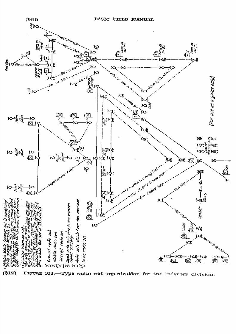
8/16/2019 (1942) FM 24-5 Signal Communication
http://slidepdf.com/reader/full/1942-fm-24-5-signal-communication 316/383
265
BASIC
FIELD MANUAL
.
@%
-SoI
',.
x;
~
~ x
¢- L~i0'
S
X
i1
<
<-~-
w-tg-----M
k>o~~~~
,,"
k>/
f'~?¢
¢
/
Mopt Mo
\
iicgXi~)
EI
\\
>c~:sI
XL
P\XS
I
e
\\
bE
~.~,~,
~,~,
j.
;A
9
,
~
t t ig<
¡dJ
cD`
oiO
C
ti
ifi
4a>,St0
,sé
l}g/X
<
P
%
(312)
FIGURE
106.-Type
radio
net
organization
for
the
infantry
division.
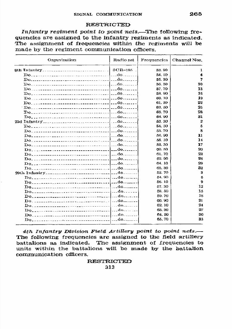
8/16/2019 (1942) FM 24-5 Signal Communication
http://slidepdf.com/reader/full/1942-fm-24-5-signal-communication 317/383
SIGNAL COMMUNICATION 265
RESTRICTED
Infantry
regiment
point to point nets.-The following
fre-
quencies are
assigned
to the infantry
regiments
as
indicated.
The
assignment
of
frequencies
within
the regiments
will
be
made
by
the
regiment
communication
officers.
Organization
Radio set
Frequencies Channel
Nos.
8th Infantry-.....
SCR-195_
52.90 1
Do .-...- do...... 54.10 4
Do .-...-. do
-
....5.30
7
Do
-.....--
do
.----
56. 50 10
Do
-.........
.
o
---- 67.70
13
Do -....
--- -
do
6.....8.90 16
Do -... .....
.
......
o --
60. ]0 19
Do
-......
do
......
61.30
22
Do
-......--------- do 62.50
26
Do -----------
-
do
-- 63.70
28
Do
-.........----- do 64.90 31
22d
Infantry ------
do
.
330
2
Do
-.....
do
5..4.50
5
Do .-.........
do
6......5.70 8
Do
-------------- -
do
--
56.90
11
Do --------------
-
do
--
58.10
14
Do
.-....-------------
- do --
59.30 17
Do
-........ do......
60.50
20
Do
--- do......
61.70 23
Do
..-......-
do
......
62.90
26
Do
-..... do
...... 64.10 29
Do -......- do
. .
.... 65.30 32
29th Infantry--
do
--- 53.70 3
Do
.-..------.----
o
54.90
6
Do
.-------------
---------.. do
56.10
9
Do
-----------
- do
--
57.30
12
Do-.-
- --
do
-.--.-
58.50
15
Do
.-.---------------------------o 59.70
18
Do
.-----------o
--
60.90 21
Do
-...
.....
.
........
o -62.10
24
Do
.-..------...-- -
do--- 63.30
27
Do------------
-
do
--
64.50
30
Do
.-..-..---
do.......
65.70
33
4th Infantry
Division
Field
ArtiUery
point to point nets.-
The
following
frequencies are assigned to the
field artillery
battalions as
indicated. The assignment
of frequencies to
units within the battalions will be made by
the battalion
communication officers.
RESTRICTED
313

8/16/2019 (1942) FM 24-5 Signal Communication
http://slidepdf.com/reader/full/1942-fm-24-5-signal-communication 318/383
265
BASIC FIELD
MANUAL
RESTRICTED
Organization
Radio set
Frequencies
Channel
Nos.
29th
FA
Battalion
-.....
. .. SCR-194__
27.70 mc
1
Do .-......
.........
o
------
28.50
3
Do -......
do
-------
29.
30
5
Do
..-.----
-
do
-.---
30.10
7
Do
----------
-
do
---
30. 90
9
Do -.....--
do -......
31.70
11
Do
...-.......
do
..-...
32.50
13
Do
..-.....
do
.-....
33.30
15
42d
FA Battalion
-......
do
-......
28.10
2
Do-.........
do
-...... 28.90
4
Do
.-...
do
-.....
29.70
6
Do
-......
do
-.....
30.50
8
Do
-....-
do
----
31.30
10
Do
-....-----
do
-.....
32.10
12
Do -...... do
-.....
32.90
14
Do-__-........-
do
- 33.70
16
44th
FA
Battalion -.....
--- do
-.....
34.10
17
Do
-...
do
....-..
34.90
19
Do .-...
do
-.....
35.70
21
Do
-.....
do-....... 36.50
23
Do -....-
-do
-.....
37.30
25
Do .-...........
do
-.....
38.10
27
Do
-...- ....
do
3....
.90
20
Do -.....-
--
do
-.....
39. 70
31
20th FA
Battalion-......
do
------
47.30
50
Do -......--
-
do -......
48.10
62
Do .-.. --------
do
-...... 48.90
54
Do .-----
do
---
49.70
56
Do -...-
-
do
50.50
58
Do
...-..
do
-.....
51.30
60
BY COMMAND
OF
MAJOR
GENERAL
WHITE:
ERNEST
R. BLUE,
Colonel, General
Staff
Corps,
Chief
of
Staff.
OFrICIAL:
/s/
MARVIN
O. ELM
Marvin
O.
Elm,
Lieutenant
Colonel, General
Stafl
Corps,
Assistant
Chief
of
Staff, G-3.
DISTRIBUTION:
S.
RESTRICTED
314
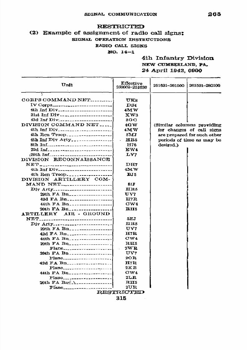
8/16/2019 (1942) FM 24-5 Signal Communication
http://slidepdf.com/reader/full/1942-fm-24-5-signal-communication 319/383
SIGNAL COMMUNICATION
266
RESTRICTED
(2) Example of assignment of radio call
signs:
SIGNAL OPERATION INSTRUCTIONS
RADIO
CALL
SIGNS
NO. 14-1
4th Infantry
Division
NEW CUMBERLAND, PA.
24
April
1942,
0900
250001-251
2611-261500 26150130-280100
OORPS
COMMAND
NET
--------
UK8
IV Corps-.....-------------------. DS4
4th Inf Div-.....
. .
4MW
31st
Inf Div-- - .
XW3
43d
Inf Div
.-
-------- 3GO
DIVISION COMMAND NET
.
4GW (Similar columns providing
4th
Inf
Div .-------- ---- 4MW
for
changes
of
call signs
4th
Rcn
Troop
----------.... SMJ
are prepared
for such other
4th
Inf Div
Arty
- . ..............R5 periods
of time as
may
be
8th Inf
-1------------------
H76
desired.)
2
2
d
Inf ------------------------
EW4
29th Inf
----------------
LY7
DIVISION RECONNAISSANCE
NET -_.... DH7
4th
Inf
Div
-....
.
4MW
4th
Rcen
Troop
------------------- BJ5
DIVISION
ARTILLERY
COM-
MAND
NET ----------------- 51J
Div
Arty
-
......................
HR5
29th FA Bn -..
.
....V7
42d FA
Bn -
.----
- H7R
44th
FA
Bn
-.-.-..
. ...
CW4
20th
FA
Bn-.---.-.-.----- RH5
ARTILLERY
AIR -
GROUND
NET
-.
S.--.R.-......EJI
Div
Arty ------------------------
HR5
29th FA
Bn-... --- UV7
42d
FA Bn
…------
-
H7R
44th
FA Bn
-
---------------.
CW4
20th FA Bn .-....... 11......15
Plane ---------- 2W R
29th
FA
Bn -.. UV7
Plane
.-
.......
.
0R
42d FA Bn…------
-
H7R
Plane ----------
2K B
44th FA Bn
…
.
. .......
W4
Plane
--------..--
2L R
20th FA Bn-------11----
R1H5
Plane
-.
..................UR
RESTRICTED
315
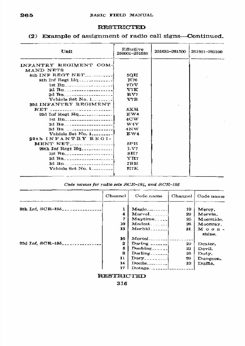
8/16/2019 (1942) FM 24-5 Signal Communication
http://slidepdf.com/reader/full/1942-fm-24-5-signal-communication 320/383
265
BASIC
FIELD
MANUAL
RESTRICTED
(2)
Example of assignment of
radio call
signs-Continued.
Unit
Effective
251631-261500
261.501-280100
250001-251630
INFANTRY
REGIMIENT
COM-
MAND NETS
8th
INF REGT
NET
-----------
5QH
8th
Inf
Regt Hlq -.-.-.---....
- 76
1st
Bn -
------- 7DV
2d
Bn-
----------------
V7K
3d Bn------------------
RV7
Vehicle
Set No.
1-
------- V7B
22d
INFANTRY REGIMENT
NET -...............
5XH
22d
Inf Regt
Hq
-. .
.......W4
Ist
Bn ------------------
4CW
2d Bn-------- - W4V
3d Bn-
. . .....NW
Vehicle
Set No.
1
-------
EW4
29th I N F A N T R Y
R E G I -
MENT
NET
.-..-.
5PH
29th Inf
Regt
Hq -.
.
.........V7
1st
Bn1
---------
-
SH7
2d Bn
-
.-.-.- --.-
YI17
3d
Bn
. ...-BH
Vehicle Set No. 1 .-- ......
KJ
Code
names
for
radio
sets
SCR-194,
and SCR-195
Channel Code
name Channel Code name
8th Inf, SCR-195
-.. . ..
1 Magic
.
e
19 Merey.
4 Marvelí
-----
22
Mervin.
7
Maytime
---- 25 Moontide.
10
Modest
---- 28
Moonray.
13
Morbid
31
M
o
o
n
-
shine.
16
Mortal
....
22d
Inf, SCR-195
---...........2 Daring
------ 20
Dexter.
5 Dashing -----
23 Devil.
8
Darling-
----- 26 Duty.
11
Dory ----
29
Dungeon.
14
Docile
-------
32 Dufie.
17
Dotage
--
-
RESTRICTED
316

8/16/2019 (1942) FM 24-5 Signal Communication
http://slidepdf.com/reader/full/1942-fm-24-5-signal-communication 321/383
SIGNAL COMMUNICATION
265
RESTRICTED
Code zames for
radio
sets SCR-194,
and SCR-195-Continued
Channel
Code name
Channel
Code
name
29th
Inf, SCR-195
-..-
-
3
Fairy
-
21 Fiction.
6
Fable
---------
24
Filly.
9
Fagin
--------
27
Forage.
12
Fertile --------
30
Forest.
15 Fervent -------
33 Fortune.
18 Fervor
.
----------
29th
FA
Bn,
SCR-194
.----------
1
Angle
---------
9
Apex.
3 Anzac
---------
11
Apron.
5 Alto
.---------
13
Acid.
7
Album.
._. ...5
Acme.
42d FA Bn,
SCR-194
----------
2 Bargain
__ 10 Boston.
4
Barkeep ------
12
Borrow.
6 Bedside
-.-.---
14
Bundle.
8
Bedtime
16
Britain.
44th
FA
Bn, SCR-194
.
.......
7
Casket
.
......5 Copper.
19 Candy
-------
27
Coddle.
21
Carton
29
Custer.
23 Castle
31 Cushion.
20th
FA
Bn,
SCR-194
.
50
Gable
56
Guernsey.
52
Gascon.
.
......8
Guilty.
54
Gallop --------
60 Gunner.
BY COMMAND
OF MAJOR
GENERAL
WH-nE:
·
ERNEST R.
BLUE,
Colonel,
General
Staff
Corps,
Chief
of
Staff.
OFFICIAL:
/s/
MARVIN
O.
ELM
Marvin
O.
Elm,
Lieutenant
Colonel,
General
Staff
Corps,
Assistant
Chief of
Staff,
G-3.
DISTRIBUTION:
S.
RESTRICTED
(3)
Example
of assignment
of
radio
frequencies
and
Call
signs.-In
this
example, the
first figure
given
is
the fre-
quency
in
kilocycles,
followed
by
the
net
call and
call sign
of the
station,
respectively.
The
final
letter
indicates
the
type
of net
as
explained
in the
example.
556773°-43- 21
317
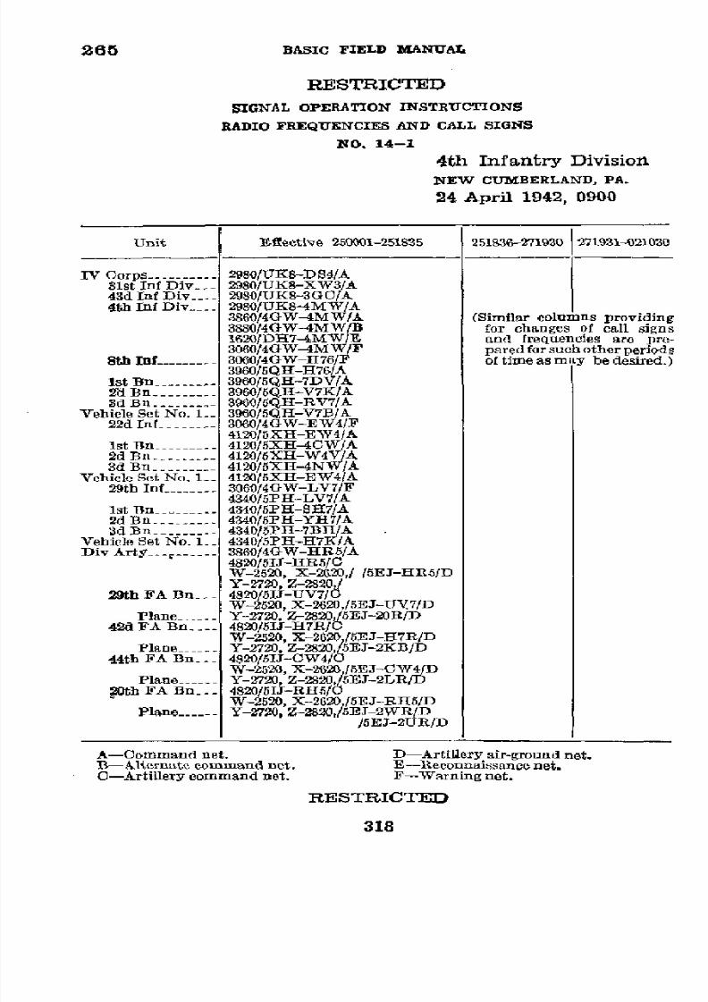
8/16/2019 (1942) FM 24-5 Signal Communication
http://slidepdf.com/reader/full/1942-fm-24-5-signal-communication 322/383
265
BASIC
FIELD
MANUAL
RESTRICTED
SIGNAL
OPERATION
INSTRUCTIONS
RADIO
FREQUENCIES
AND
CALL
SIGNS
NO.
14-1
4th
Infantry
Division
NEW CUMBERLAND,
PA.
24
April
1942, 0900
Unit
Effective
250001-251S35
251836-271930
271931-021030
IV
Corps
-.
.
.2980/UKS-DS4/A
31st Inf
Div
-. 2980/UK8-XW3/A
43d
Inf
Div -.--
2980/UK8-3GC/A
4th
Inf Div -
2980/UK8-4MW/A
3860/4GW-4MW/A
(Similar
columns
providing
3880/4GW-4MW/B
for
changes
of call signs
1620/DR7-4MW/E
and
frequencies
are pre-
3060/4GW-4MW/F
pared
for
such
other
periods
8t
------f
3060/4W-H76/F
of
time
as
may
be desired.)
3960/5QlI-H76/A
1st
Bn
---------
3960/5QH-7DV/A
2d
Bn
---------
3960/5QH-V7K/A
3d
Bn
-...
.
960/5QH-RV7/A
Vehicle Set
No.
1.-
3960/5QHI-V7B/A
22d
Inf
----.
306014GW-EW4/F
4120/5XH-EW4/A
1st Bn
-
4120/SXH-4CW/A
2d Bn
------.
4120/5XH-W4V/A
3d Bn
...-
....
4120/5XH-4NW/A
Vehicle Set
No.
1_ 4120/5XH-EW4/A.
29th Inf
3060/4OW-LV7/F
4340/5PH-LV7/A
1st Bn -----
4340/5PH-SH7/A
2d Bn
-
-----..
4340/5PH-YU7/A
3d
Bn
..- .
....
340/5PH-7B1/A
Vehicle
Set No.
1_
4340/5PH-H7K/A
Div
Arty_
. .
...
860/4GW-HR5/A
4820/5IJ-HR5/C
W-2520,
X-2620,[
/5EJ-HR5/D
Y-2720, Z-2820,/
29th FA
Bn_.-
4820/5I1-UV7/C
W-2520,
X-2620,/5EJ-UV7/D
Plane-
.-- Y-2720,
Z-2820,/5EJ-20R/D
42d FA Bn -.--
4820/5IJ-1H7R/C
W-2520,
X-2620,/5EJ-H7R/D
Plane -----
Y-2720,
Z-2820,/5EJ-2KB/D
44th
FA Bn
---
4820/5IJ-CW4/O
W-2520,
X-2620,/SEJ-CW4/D
Plane
--
Y-2720,
Z-2820,/5EJ-2LR/D
20th
FA
Bn --
4820/5IJ-RH5/C
W-2520,
X-2620,/5EJ-RH5/D
Plane
------
Y-2720,
Z-2820,/5EJ-2WR/D
/5EJ-2UR/D
A-Command
net.
D-Artillery
air-ground
net.
B-Alternate
command
net.
E-Reconnaissance
net.
C-Artillery
command
net.
F-Warning
net.
RESTRICTED
318
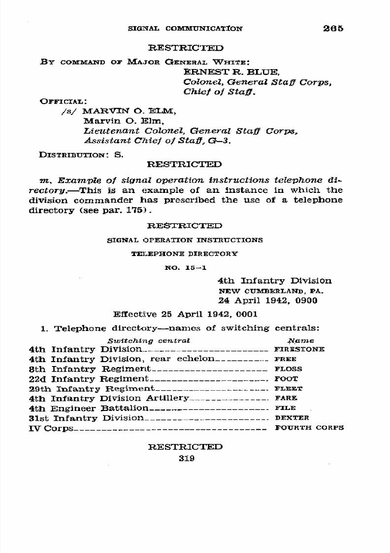
8/16/2019 (1942) FM 24-5 Signal Communication
http://slidepdf.com/reader/full/1942-fm-24-5-signal-communication 323/383
SIGNAL
COMMUNICATION
265
RESTRICTED
BY
COMMAND
OF MAJOR GENERAL
WHITE:
ERNEST
R. BLUE,
Colonel,
General
Staff Corps,
Chief of Staff.
OFFICIAL:
/s/
MARVIN
O. ELM,
Marvin
O. .Elm,
Lieutenant
Colonel,
General
Staff
Corps,
Assistant Chief
of
Staff,
G-3.
DISTRIBUTION:
S.
RESTRICTED
m. Example
of signal
operation
instructions
telephone
di-
rectory.-This
is
an example of
an
instance
in which
the
division
commander
has prescribed
the
use of
a
telephone
directory
(see par.
175>).
RESTRICTED
SIGNAL OPERATION INSTRUCTIONS
TELEPHONE
DIRECTORY
NO.
15-1
4th
Infantry
Division
NEW CUMBERLAND,
PA.
24
April
1942, 0900
Effective
25 April
1942, 0001
1.
Telephone
directory-names
of switching
centrals:
Switching central
Mame
4th Infantry
Division
.------------------
-
FIRESTONE
4th
Infantry
Division,
rear
echelon-_________
FREE
8th
Infantry
Regiment---------------------
FLOSS
22d
Infantry
Regiment
--------------------.
FOOT
29th Infantry
Regiment_----------_------.--
FLEET
4th
Infantry
Division
Artillery______--------.
FARE
4th
Engineer
Battalion
-----------..---------
FILE
31st
Infantry
Division________
------------.
DEXTER
IV Corps-----------------------------------
FOURTH
CORPS
RESTRICTED
319

8/16/2019 (1942) FM 24-5 Signal Communication
http://slidepdf.com/reader/full/1942-fm-24-5-signal-communication 324/383
265
BASIC
FIELD
MANUAL
RESTRICTED
RED,
WHITE, BLUE,
or
GREEN
added to
the telephone
directory
name
of
the
regiment
switching
central
indicates
the
switch-
ing
central
of the
1st,
2d,
3d,
or
4th
Battalion
respectively.
Example:
FLEET
BLUE
Is
the directory
name
of the switching
central
of the 3d Battalion
of the 29th Infantry
Regiment.
2.
Telephone
directory
numbers-officers,
and
offices:
Number
Title
1
______ C-1 or 8-1
2
-------
G-2
or
S-2
3 -------
G-3
or S-3
4 ------- G-4 or
S-4
5
-------
Chief
of staff
or
executive officer
6
------- Commanding
officer
7-------
Adjutant
(division
and
higher
units)
8 -------
Ordnance
officer
9_------
Inspector
10-------
Signal
or
communication
officer
11-------
Message
center
(incoming)
12-------
Message
center (outgoing)
13------- Aide-de-camp
14_______
Air
officer
15-------
Engineer
offlcer
16-------
Surgeon
or
medical officer
17------- Judge
advocate
18-------
Finance
officer
19-------
Chaplain
20-------
Postal officer
21-------
Quartermaster
(not
supply
officer)
22
__----
Chief
of artillery
or
artillery
officer
23-------
Chemical or
gas officer
24-__--_-
Liaison officer
25…------
Munitions
officer
26-------
Pigeon
loft
27
-------
Provost
marshal
28
------
Radio
station
29-------
Reconnaissance
officer
30-------
Telegraph
office
31------_
Telephone wire
chief
or trouble
chief
RESTRICTED
320

8/16/2019 (1942) FM 24-5 Signal Communication
http://slidepdf.com/reader/full/1942-fm-24-5-signal-communication 325/383

8/16/2019 (1942) FM 24-5 Signal Communication
http://slidepdf.com/reader/full/1942-fm-24-5-signal-communication 326/383
265
BASIC
FIELD
MANUAL
n.
Example
of
signal operation
instructions
wire
tagging
code.
RESTRICTED
SIGNAL
OPERATION
INSTRUCTIONS
WIRE
TAGGING
CODE
NO.
16-1
4th Infantry Division
NEW
CUMBERLAND,
PA.
24 April
1942, 0900
Effective 25 April
1942, 0001
1.
The code names
listed
herein
are
for
use
in designating
units on
wire
circuit
tags.
2.
The code
names
will be used
as
prescribed in
paragraph
189 of
FM 24-5.
3.
Code names in the first column
will
remain
in
force
until
canceled by division
order,
at
which
time the
second
column
will
be
used.
4.
Lines will
be tagged in
accordance with FM 24-5.
First Second
period period
Unit
Code
Code
name
ame
4th Division
.--------------------------------
sp Owl
4th
Division
Artillery
-.............................
Cat
Egg
Sth
Infantry
-.............................................
Dog
Perch
1st
Battalion-
.....................
Dough Peach
2d
Battalion
-...-- --- ---
- Doubt Pet
3d
Battalion
-Dock
Pearl
l2th
Infantry
----------------------
-
Frog Sail
1st
Battalion
-.................
Fret
Salt
2d
Battalion
----------------
-
Frail
Sand
3d
Battalion
-..............
Fruit
Sap
22d
Infantry
.-..................
Rat Cow
1st
Battalion -.............................
Ramp
Coot
2d
Battalion
.-.
.
..........................ace
Corn
3d Battalion
.-------------------
Rail
Cock
4th Signal
Company ---------------------............
Mud
Dirt
34th Quartermaster
Battalion
------------------------------
Duck
Hen
RESTRICTED
322

8/16/2019 (1942) FM 24-5 Signal Communication
http://slidepdf.com/reader/full/1942-fm-24-5-signal-communication 327/383
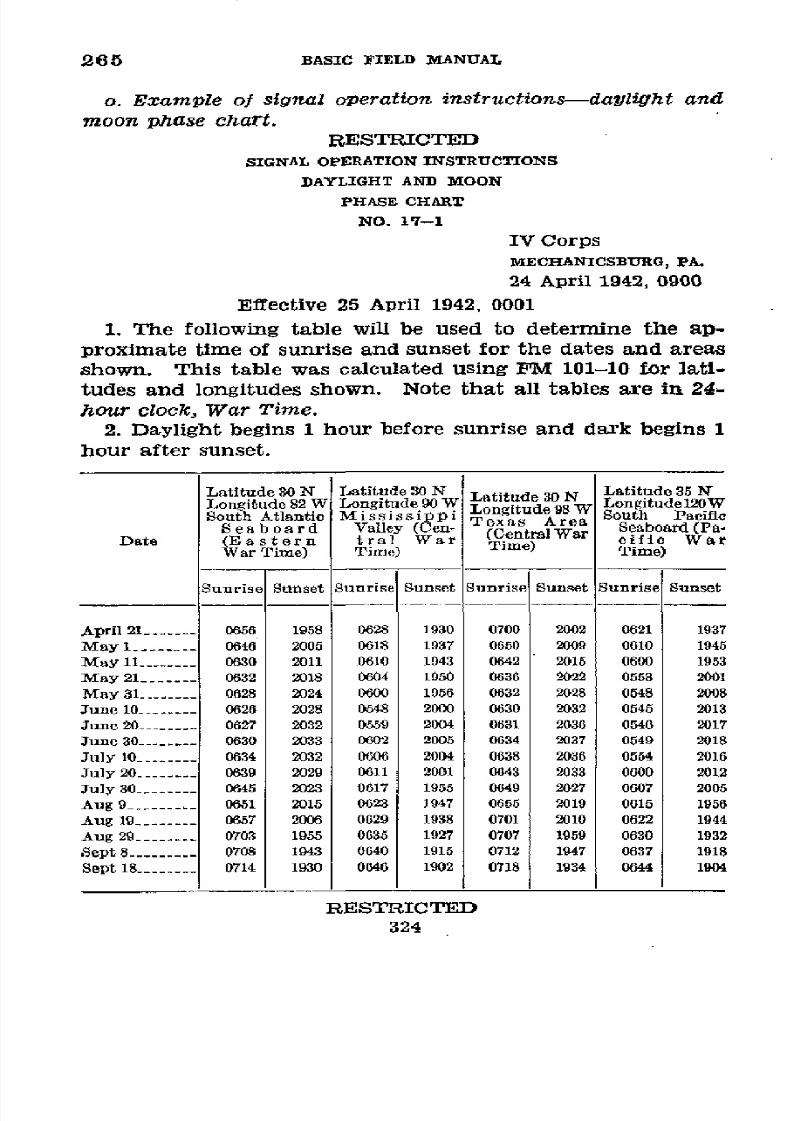
8/16/2019 (1942) FM 24-5 Signal Communication
http://slidepdf.com/reader/full/1942-fm-24-5-signal-communication 328/383
265
BASIC
FIELD
MANUAL
o.
Example
of signal
operation
instructions-daylight
and
moon piase
chart.
RESTRICTED
SIGNAL
OPERATION
INSTRUCTIONS
DAYLIGHT AND MOON
pHASE
CHART
NO.
17-1
IV Corps
MECHANICSBURG,
PA .
24
April
1942, 0900
Effective
25
April
1942, 0001
1. The
following
table
will
be
used to
determine the
ap-
proximate
time of sunrise
and sunset
for
the dates
and areas
shown.
This table
was
calculated
using
FM
101-10 for
lati-
tudes
and longitudes
shown.
Note
that
all
tables
are in
24-
hour
clock,
War Time.
2. Daylight
begins 1
hour
before sunrise
and
dark
begins 1
hour
after
sunset.
Latitude
30
N
Latitude
30 N Latitude 30 N
Latitude 35
N
Longitude
82W
Longitude
90
W
Lonitude
98
Longitudel20W
South
Atlantie M i
s
s
i gitude
98 South
Pacific
Seaboard
Valley
( -
(Central
War Seaboard (Pa
Date (Eastern
tral
War
War
Time) Time)
War
Time)
Time)
Sunrise
Sunset
Sunset Sunrise
Sunset
Sunrise
Sunset
April
21 -
0656
1958
0628
1930
0700 2002
0621
1937
May 1
-.-
- 0646
2005 0618
1937
0650
2009 0610
1945
May 11 --------
0630 2011
0610 1943
0642 2015
0600 1953
May
21 ---.
0632
2018
0604
1950
0636
2022 0553
2001
May
31 .------ 0628
2024
0600
1956 0632
2028 0548
2008
June
10
_-...___
0626 2028
0548
2000 0630
2032 0545
2013
June 20 --------
0627
2032
0559
2004 0631 2036
0546
2017
June 30
---. --- 0630
2033 0602
2005 0634
2037
0549 2018
July
10
-_------
0634
2032 0606
2004
0638
2036
0554
2016
July 20
-------- 0639
2029 0611 2001
0643 2033
0600 2012
July 30 --------
0645
2023 0617
1955 0649 2027
0607 2005
Aug
9 ------. 0651
2015 0623
1947
0655 2019
0615
1956
Aug
19-.----
0657
2006
0629
1938 0701 2010
0622
1944
Aug
29
....-
0703
1955
0635 1927 0707
1959
0630
1932
Sept 8.-..
. .708
1943 0640
1915 0712
1947
0637
1918
Sept
18
--------
0714
1930
0646 1902
0718
1934
0644
1904
RESTRICTED
324

8/16/2019 (1942) FM 24-5 Signal Communication
http://slidepdf.com/reader/full/1942-fm-24-5-signal-communication 329/383
SIGNAL
COMMUNICATION
265
RESTRICTED
New
First Full
Last New
First Full Last
Moon
Quarter
Moon Quarter Moon Moon
Quarter
January
------
16 24 2
10
6 13 21 29
February ------ 15 22
1
8
4 11 20
27
March 16 24 2 9
6
13 21
28
April-
15 23
Iland 30
7
4 12 20 27
May -----
15
23 30 7 4 12 19 26
June
-- 13 21
28 5 2 10
18
24
July
-- 13
21 27
5 2and31
10 17 23
August-.----
11 19
25
3
30
8
15
22
September
---- 10 17 24 2 29 7 13 21
October 8..- 16 23 2 28 6 13
20
November-
...
15 22 land30 27 4
11
19
December ... . 14 22 30
26
4 11 19
BY
COMMAND OF
LIEUTENANT
GENERAL
SMITH:
L.
M.
JONES,
BrigadierGeneral, General Staff Corps,
Chiel of
Staff.
OFFICIAL:
/S/ R. L.
BROWN
R. L.
Brown,
Lieutenant Colonel,
General Staff
Corps,
Assistant Chief of Staff,
G-3.
DISTRIBUTION:
S.
RESTRICTED
325

8/16/2019 (1942) FM 24-5 Signal Communication
http://slidepdf.com/reader/full/1942-fm-24-5-signal-communication 330/383
265
BASIC FIELD MANUAL
p.
Exawn$pe
of signal operation
instructions
prearranged
message
code.
CONFIDENTIAL
SIGNAL OPERATION
INSTRUCTIONS
PREARRANGED MESSAGE CODE
NO. 18-1
4th
Infantry Division
NEW
CUMBERLAND, PA.
24
April 1942, 0900
Effective
25
April
1942,
0001
1.
This
code
is to
be
used when operating
with division
headquarters
signal communication
units. It is intended
pri-
marily
for the
rapid
transmission
of
certain
messages
when
danger of
hostile
interception exists and
transmissions in
the
clear are
not
authorized.
Other
cryptograph
methods should
be used for meanings
not listed herein,
when secrecy is
required.
2. Regiment
and separate
units of
this
division
may
pre-
pare prearranged
messages
appropriate for
their
use. Such
prearranged
message
codes
will
be changed
frequently.
(See
par.
48d,
FM
24-5.)
Code group
Telegraphic
Telephonio
Meaning
AB
AFIRM BAKER
Combat
team
8 now at_
_-___-____.
CP
CAST FOX
Combat
team 22
now
at
____________
RY
ROGER
YOKE
Combat
team
29
now
at
____________
GJ
GEORGE JIG No change in enemy
situation.
KN
KING NEGAT
Enemy
contacted.
LO LOVE OPTION
Corps commSand post now
at________.
TY TARE
YOKE Attack
launched.
BY COMMAND OF MAJOR
GENERAL
WHITE:
ERNEST
R. BLUE,
Colonel, General
Staff Corps,
Chief of
Staff.
OFFICIAL:
/s/ MARVIN
O.
ELM
Marvin
O. Elm,
Lieutenant
Colonel,
General Staff
Corps,
Assistant
Chief
of
Staff,
G-3.
DISTRIBUTION: S.
CONFIDENTIAL
326
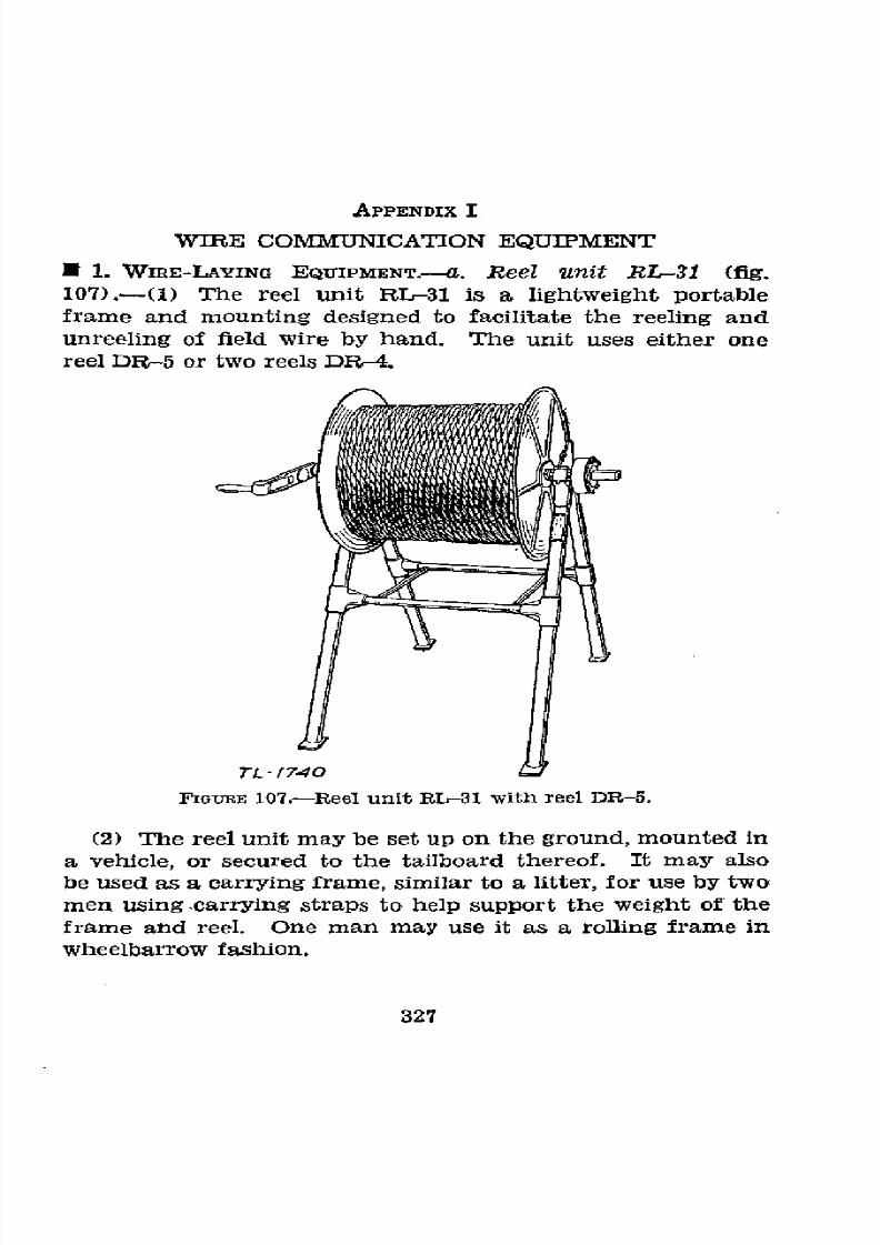
8/16/2019 (1942) FM 24-5 Signal Communication
http://slidepdf.com/reader/full/1942-fm-24-5-signal-communication 331/383
APPENDIX I
WIRE
COMMUNICATION
EQUIPMENT
1.
WIRE-LAYING
EQUIPMENT.--. Reel
unit
RL-31 (fig.
107).-(1)
The
reel unit
RL-31 is a
lightweight
portable
frame
and
mounting
designed to
facilitate the reeling and
unreeling
of
field
wire
by
hand. The
unit
uses
either
one
reel DR-5 or two
reels
DR-4.
TL- /740
PFIGRE 107.-Reel unit RL31 with reel DR-5.
(2) The
reel
unit
may
be
set
up
on
the ground, mounted
in
a
vehicle,
or
secured
to
the
tailboard thereof.
It
may also
be used as a carrying
frame,
similar to
a litter,
for use
by
two
men
Using
carrying
straps to help
support
the
weight
of
the
frame
and
reel.
One
man
may
use
it as
a
rolling frame
in
wheelbarrow
fashion.
327

8/16/2019 (1942) FM 24-5 Signal Communication
http://slidepdf.com/reader/full/1942-fm-24-5-signal-communication 332/383
BASIC
FIELD
MANUAL
(3)
The
reel
unit
consists
of
a
folding
tubular
aluminum
alloy frame
with
bearings
for a steel
axle
equipped
with
a
removable
hand
crank.
A
brake
is provided
to prevent
the
reels
from overspinning
while
unreeling.
Two
tailboard
hangers
with
bolts
are
provided
to facilitate
mounting
the
reel
unit
on
the tailboard
of
a
truck
or
wagon.
Four
toe
-
fo
re/tose
hanoleN
J57Z
PIlanRE
108.-Axle
RL-27
showing
removable
handle.
plates
are
provided
to
hold the
reel
unit
securely
in
place
when
it
is mounted
on the
floor
of the
vehicle.
(See
TM
11-362.)
b. Axles
RL-27
and
RL-27-A
(figs.
108
and
109) .-
The
axle
RL-27 is
a
simple
form
of
wire-laying
device
for
laying
short
fIGoRE
109.-Axle
RL-27
with
reel DR-4.
local
circuits
by
hand.
It
can
be used
to
lay
lines
where
conditions
do not
permit
the use
of
other
wire-laying
equip-
ment.
The axle
RL-27
is
a
machined
steel
bar,
about
2
feet
long,
with
two
knurled
aluminum
handles,
one
of which
is
permanently
fixed
to the
bar.
The
other
can
be removed
to
328
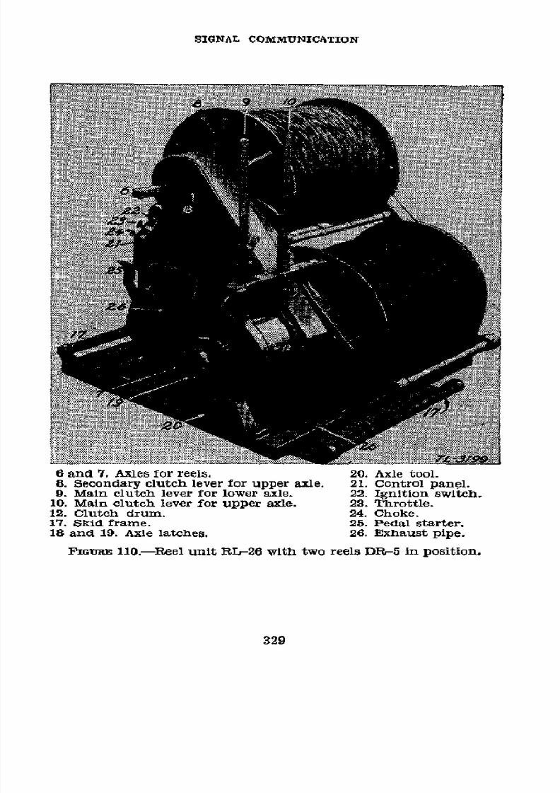
8/16/2019 (1942) FM 24-5 Signal Communication
http://slidepdf.com/reader/full/1942-fm-24-5-signal-communication 333/383
SIGNAL
COMMUNICATION
6
and
7. Axles
for reels.
20. Axle
tool.
8. Secondary
clutch lever for upper
axle.
21. Control panel.
9.
Main
clutch
lever
for
lower axle. 22. Ignition
switch.
10.
Main
clutch
lever
for upper
axle. 23.
Throttle.
12.
Clutch
drum. 24. Choke.
17. Skid
frame.
25.
Pedal
starter.
18 and
19.
Axle latches.
26. Exhaust
pipe.
F'iGIRE 110.-Reel
unit RL-26 with two reels DR-5
in position.
329

8/16/2019 (1942) FM 24-5 Signal Communication
http://slidepdf.com/reader/full/1942-fm-24-5-signal-communication 334/383
BASIC
FIELD
MANUAL
permit placing
a
reel
DR-4
on the axle.
The
reel
DR-5
will
not fit
on the axle
RL-27.
The axle RL-27-A
is
a modifica-
tion of
the
axle RL-27 with an
improved type of roller
bearings.
c.
Reel
unit
RL-26-A.-Reel
unit RL-26-A
is
a
transport-
able
wire-laying
and wire-recovering
machine intended
primarily
for
temporary
or permanent
installation
in
motor-
trucks.
It
may
be
operated
while the vehicles
are stationary
or in
motion. Dismounted,
the
unit may
also be
operated
in
temporary fixed
positions
on
the
ground.
All component
parts
are
assembled
on
a
skid
frame
which can
be
quickly
installed in the back of a vehicle. The
capacity
of the unit
is two
reels
DR-5;
mounted in
position
for paying
out
or
reeling
in the wire. The
individual reels
are
readily replace-
able.
The
wire
can
be
payed
out from
either
reel
singly or
from
both
simultaneously,
and
means
are provided
for
brak-
ing
the
reels to
prevent overspinning.
By
means
of
a
small
gasoline engine, the wire can be
reeled
in
on
either
reel
sepa-
rately
or on
both
at
the
same
time
(fig. 110).
It
can
also
be
reeled
in by hand cranking
when
the engine
is
inoperative.
The
weight
of
the
RL-26-A, without
reels, is about 346
pounds.
The unit
fully
loaded
with
2
miles of
wire weighs
approximately
690
pounds.
The method of laying wire from a reel unit RL-26-A
mounted in:a truck
is shown in figure 111.
More complete
descriptions
of
the
operation and maintenance
of
these
reel
units may
be
found in
TM 11-360.
d. Reel
cart
RL-16 (fig.
112).-This
is a
cart
which
may
be
pulled by
hand or
towed
behind a communication
cart. It
should not be towed behind
a
fast-moving
vehicle.
Each
reel
cart
carries two
reels DR-4
which are removable,
and
the
axle
is
equipped with a
detachable
hand
crank for
recovering
wire on the reels. A single reel
DR-5
can be placed
on the
cart
by
removing
the
spacer
bar
on
the
axle.
The
reel
cart
may
be taken
apart
for
packing.
e.
Reel
equipment
CE-11.-This
is a breast
reel and tele-
phone
handset carried
by
the
individual
soldier
as
illus-
trated
in
figure 113.
It consists
of reel unit RL-39 and
hand-
set TS-10. The reel unit RL-39
comprises a
reel DR-8,
carry-
ing
handles for
the
reel which
incorporate
the supported
bearings,
a square-shaft axle
with
crank for
rewinding,
and
330

8/16/2019 (1942) FM 24-5 Signal Communication
http://slidepdf.com/reader/full/1942-fm-24-5-signal-communication 335/383
SIGNAL
COMMUNICATION
FIGURE
Ill.-Laying
field
wire from
truck-mounted
reel unit
RL-26-A.
331
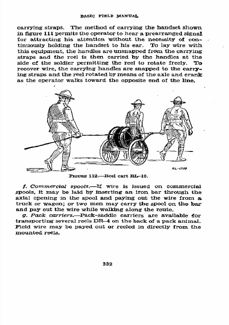
8/16/2019 (1942) FM 24-5 Signal Communication
http://slidepdf.com/reader/full/1942-fm-24-5-signal-communication 336/383
BASIC FIELD MANUAL
carrying straps.
The
method of carrying the handset shown
in figure 111 permits the
operator to
hear a prearranged
signal
for
attracting
his
attention
without
the necessity of con-
tinuously holding
the
handset
to
his ear.
To
lay
wire
with
this
equipment,
the handles
are unsnapped
from the carrying
straps and
the
reel
is then
carried
by
the
handles
at the
side
of
the
soldier
permitting
the reel
to
rotate
freely.
To
recover wire,
the
carrying
handles
are snapped to the
carry-
ing straps
and the
reel rotated by means of
the axle and crank
as the operator walks toward the opposite
end of the
line.
Z L-t72e
FIGUi
112.-aReel
cart
RL-16.
f. Commercial
spools.-If wire
is
issued on commercial
spools, it may
be laid by inserting
an iron bar
through the
axial opening
in
the
spool and
paying out
the wire from a
truck
or wagon;
or
two men may carry
the
spool on the bar
and
pay
out the
wire while
walking along
the route.
g. Pack carriers.-Pack-saddle
carriers
are
available
£or
transporting
several
reels
DR-4
on
the
back
of
a
pack animal.
Field wire
may
be
payed
out
or reeled in
directly from the
mounted reels.
332

8/16/2019 (1942) FM 24-5 Signal Communication
http://slidepdf.com/reader/full/1942-fm-24-5-signal-communication 337/383
SIGNAL
COMMUNICATION
FGuREi 113.-Reel equipment
CE-11.
2.
TYpES
OF
FIELD
TELEPHONES.-a. Telephone EE-8-A--
The field telephone EE-8-A
can be
used
on either local battery
or common
battery systems
and
has
other
applications
de-
scribed
in
TM 11-333. Two batteries BA-30
are required
with
the instrument;
these
are not supplied as part of the tele-
phone and must
be
requisitioned
separately.
An
external
3-
volt
battery
may
be used instead of the two batteries
BA-30
provided it
is
connected
to
the external
battery
binding posts
and the internal batteries
are
removed. A view
of
the tele-
phone EE-8-A with the
case opened is shown
in
figure 114.
The handset and cord fit into the compartment shown when
the
instrument is
not
in
service.
556773'-43 22
333
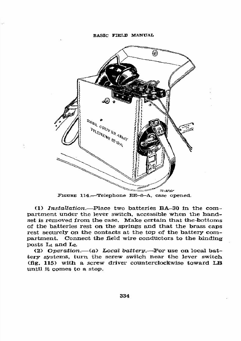
8/16/2019 (1942) FM 24-5 Signal Communication
http://slidepdf.com/reader/full/1942-fm-24-5-signal-communication 338/383

8/16/2019 (1942) FM 24-5 Signal Communication
http://slidepdf.com/reader/full/1942-fm-24-5-signal-communication 339/383
SIGNAL
COMMUNICATION
115.-Positnhandsetlever swtch
n
3 comm
PGURE 115.-Position
of handset
on
lever
switch in Common
battery
operation.
1.
To signal.-Turn
the generator
rapidly
for
several
turns.
The
position
of
the handset
or
lever
switch is immaterial.
2.
To
talk and listen.-Hold the handset with
the
re-
ceiver
to
the
ear.
While
talking, operate
the
handset
switch with
the
thumb and talk
directly
into
the transmitter.
When
listening
only, re-
lease the switch
to
conserve the
battery strength;
this
does
not reduce
the
receiver
sensitivity, but
does cut out
any extraneous noises
originating
near
the
telephone.
3.
To ring o#.-If the circuit is established through a
switchboard,
ring
off by two
or
three sharp
turns of the
generator
when the
conversation
is
completed.
This indicates to the switchboard
operator that
the
conversation is ended or that
a
new
connection
is desired.
After
ringing
off,
if
a new connection is not
desired,
replace the
handset in the case,
leaving the
cord hanging
out.
(b) Common
battery.-Turn the screw switch
near
the lever
switch clockwise
toward CB
with a
screw driver
until
it comes
335

8/16/2019 (1942) FM 24-5 Signal Communication
http://slidepdf.com/reader/full/1942-fm-24-5-signal-communication 340/383
BASIC
FIELD
MANUAL
to
a stop.
The
lever
switch
(fig. 115)
is
an
essential part
of
the
telephone
in common
battery
operation,
corresponding
to
the
hook
or
plunger
switch on commercial
telephones. The
handset
when
not in
use
is
placed
with
the transmitter
up,
resting
upon
and depressing
the lever
switch.
This
is the
position
of
the handset
on
the lever
switch
shown
in
figure
115.
1.
To
can/.-Remove
the handset
from
its
position on
the lever
switch. (The
lever
switch is
then re-
leased,
as shown
by the
dotted lines
in figure
114.) If
the
switchboard
operator
does
not
answer,
depress
and
release the
lever
switch
slowly several
times,
which
flashes
the line lamp
at
the
switchboard,
giving notice
to
the operator.
2. To talk
and listen.-Proceed
as
in
(a)
2
above.
The
BA-30
batteries
furnish
talking current
for
com-
mon battery as well
as
local
battery operation.
3.
To
recall
operator.-Push
he
lever
switch down
and
release
slowly
several
times.
4.
To
indicate
completion
of call.-Place
the
handset
as shown in figure
115,
depressing
the
lever
switch.
(3)
To
close
station.-Before
disconnecting
the telephone
from
a wire circuit,
the
person
removing
the telephone
should
call
the switching
central or
other party
on
the
line
informing
him that
the
telephone
is
being
removed
from
the
circuit.
Remove
the
connections to
Li
and
L2.
Remove
the
batteries
BA-30,
unless
the
telephone
is
to
be
installed
on another
cir-
cuit
immediately,
as
highly
corrosive
chemicals injurious
to
the
telephone
leak
out
of run-down
batteries.
Fold
the
rubber-covered
cord
loosely
into folds
about
as long
as the
handset,
place
the
folds
alongside
the
handset,
and
insert
the handset
(receiver
end
first)
into the
case
as
shown
in
figure
113.
The
cord
may
also be
conveniently
handled
by
holding
the handset
in the
left
hand,
placing the
thumb
against
the
receiver
case,
and
wrapping
the
cord
in
long
folds
completely
around
the handset.
In either
case, do
not
wrap
the
cord
around
the handle
of
the
handset
as that
is injurious
to the
cord
and
may
operate
the handset
switch.
The switch
must
be left
in the
neutral
position
(wings
parallel
to
the
336
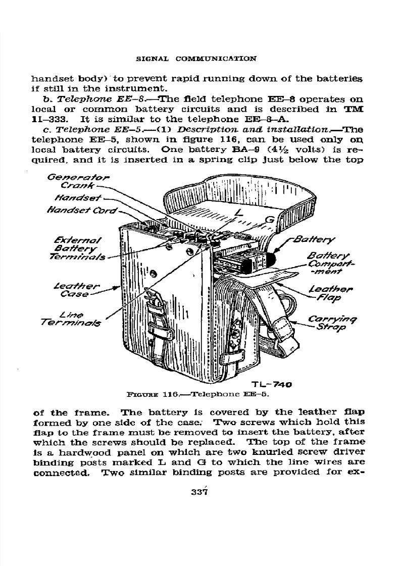
8/16/2019 (1942) FM 24-5 Signal Communication
http://slidepdf.com/reader/full/1942-fm-24-5-signal-communication 341/383
SIGNAL COMMUNICATION
handset
body)
to prevent
rapid running
down
of
the batteries
if still in
the instrument.
b. Telephone
EE-8.-The fleld telephone
EE-8 operates
on
local
or
common
battery
circuits
and
is
described
in
TM
11-333. It
is similar to the telephone EE-8-A.
c.
Telephone
EE-5.-(1)
Description
and
installation--The
telephone
EE-5,
shown in
figure
116, can be
used only
on
local
battery
circuits.
One battery
BA-9
(41/2
volts)
is re-
quired, and
it
is
inserted
in a
spring clip just
below the
top
Generafoir
I ,qAlIh,,_/I
I
i1
:iCompot/-
fer/
L:..er
ermnG//s
'
Stmera
Le/efher7ljIlll\I
',
tlop
TL- 740
IGURE
116.-Telephone EE-5.
of
the
frame. The
battery
is
covered by
the
leather
flap
formed by
one side
of
the case.; Two screws
which
hold
this
flap to the frame must be removed to insert the battery,
after
which the screws should be replaced. The top of
the
frame
is a hardwood
panel on
which
are two knurled screw
driver
binding
posts marked L
and
G to which the
line wires
are
connected.
Two similar
binding posts are
provided
for
ex-
337
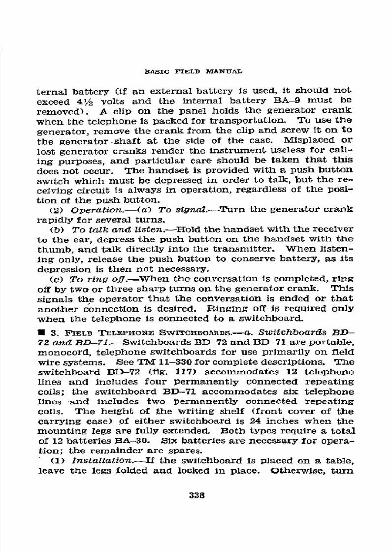
8/16/2019 (1942) FM 24-5 Signal Communication
http://slidepdf.com/reader/full/1942-fm-24-5-signal-communication 342/383
BASIC
FIELD
MANUAL
ternal
battery
(if an
external
battery
is
used,
it should
not
exceed
41/2
volts
and
the
internal
battery
BA-9
must
be
removed).
A
clip
on
the panel
holds
the
generator
crank
when
the
telephone
is
packed
for
transportation.
To
use
the
generator,
remove
the
crank
from
the
clip
and screw
it on
to
the
generator-shaft
at
the
side
of
the
case.
Misplaced
or
lost
generator
cranks
render
the
instrument
useless
for
call-
ing
purposes,
and particular
care should
be
taken
that
this
does
not occur.
The
handset
is
provided
with
a push
button
switch
which
must
be depressed
in
order
to
talk, but
the
re-
ceiving
circuit
is always
in
operation,
regardless
of
the
posi-
tion
of
the push
button.
(2)
Operation.-(a)
To signal.-Turn
the
generator
crank
rapidly
for several
turns.
(b)
To talk
and
listen.-Hold
the
handset
with
the
receiver
to the
ear,
depress
the
push
button
on
the
handset
with
the
thumb,
and talk
directly
into
the
transmitter.
When
listen-
ing only,
release
the push
button
to
conserve
battery,
as its
depression
is
then
not
necessary.
(c)
To
ring
off.-When
the
conversation
is completed,
ring
off
by two
or
three
sharp
turns
on
the generator
crank.
This
signals
the
operator that
the
conversation
is
ended
or
that
another
connection
is
desired.
Ringing
off
is required
only
when
the
telephone
is
connected
to
a
switchboard.
U 3. FIELD
TELEPHONE
SWITCHBOARDS.---.
Switchboards
BD-
72
and
BD-71.-Switchboards
BD-72
and
BD-71
are portable,
monocord,
telephone
switchboards
for
use
primarily
on
field
wire
systems.
See
TM 11-330
for complete descriptions.
The
switchboard
BD-72 (fig.
117)
accommodates
12 telephone
lines
and
includes
four
permanently
connected
repeating
coils;
the
switchboard
BD-71
accommodates
six telephone
lines
and includes
two
permanently
connected
repeating
coils.
The
height
of the
writing
shelf
(front
cover
of
the
carrying
case)
of
elther
switchboard
is
24
inches
when
the
mounting
legs
are
fully
extended.
Both
types
require
a total
of 12
batteries
BA-30.
Six
batteries
are necessary
for
opera-
tion; the
remainder are
spares.
(1) Installation.-If
the switchboard
is placed
on a
table,
leave the
legs
folded
and locked
in
place. Otherwise,
turn
338
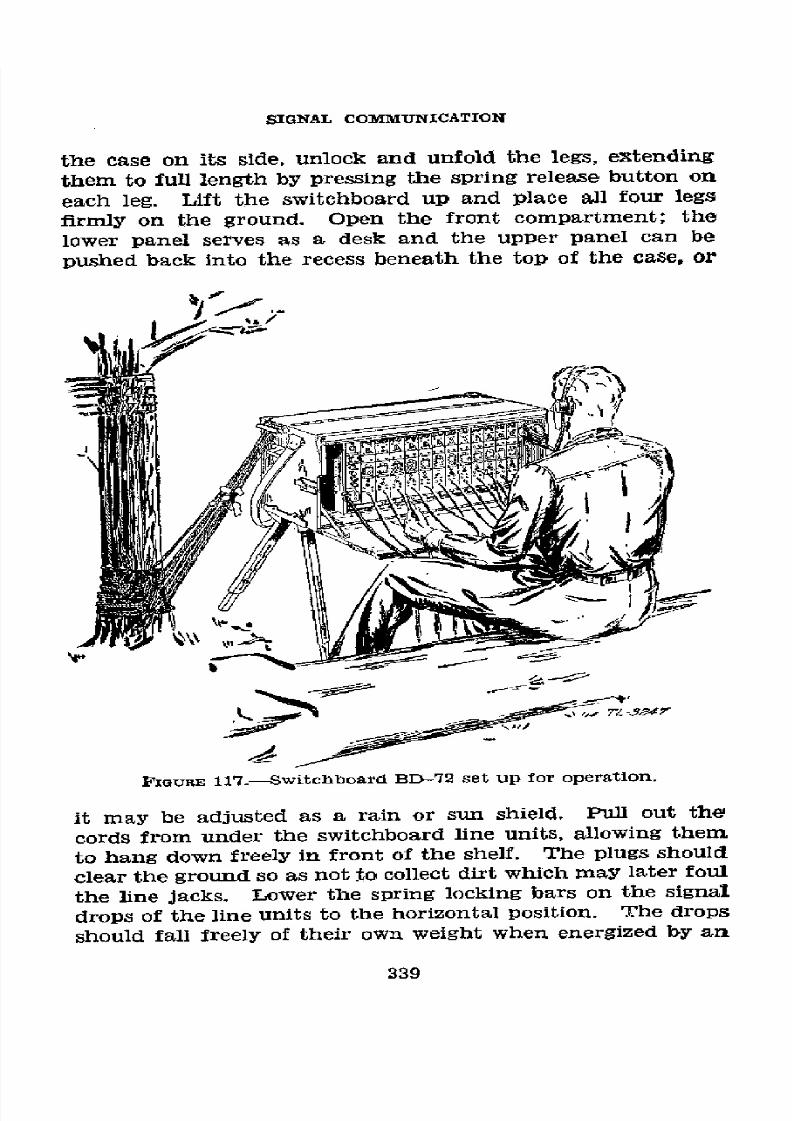
8/16/2019 (1942) FM 24-5 Signal Communication
http://slidepdf.com/reader/full/1942-fm-24-5-signal-communication 343/383
SIGNAL
COMMUNICATION
the
case
on
its
side,
unlock
and
unfold
the
legs,
extending
them
to
full
length
by
pressing
the
spring
release
button
on
each
leg.
Lift
the
switchboard
up
and
place
all
four
legs
firmly on
the
ground.
Open
the front
compartment;
the
lower
panel
serves
as
a
desk
and
the
upper
panel
can
be
pushed
back
into
the
recess
beneath
the
top
of
the
case,
or
FIGIURE
117.-Switchboard
BD-72
set
up
for
operation.
it
may
be
adjusted
as
a
rain
or
sun
shield.
Pull
out
the
cords
from
under
the
switchboard
line
units,
allowing
them
to
hang
down
freely
in
front
of
the
shelf.
The
plugs
should
clear
the
ground
so
as
not
to
collect
dirt
which
may
later
foul
the
line
jacks.
Lower
the
spring
locking
bars
on
the
signal
drops
of
the
line
units
to
the
horizontal
position.
The
drops
should
fall
freely
of
their
own
weight
when
energized
by
an
339

8/16/2019 (1942) FM 24-5 Signal Communication
http://slidepdf.com/reader/full/1942-fm-24-5-signal-communication 344/383
BASIC
FIELD
MANUAL
incoming
signal;
this may
require
a slight forward
tilt of
the
switchboard
front.
Open
the
battery
case
inside
the
rear
compartment
(fig.
118).
Place
two
batteries
BA-30
in
series
FIGURE
118.-Rear
view
of
switchboard
BD-72,
with compartments
opened.
in
the
right-hand
division of
the
case; these
furnish
talking
current
for the
operator's
set. Place
two
pairs
of
batteries
in
series
in the left-hand
division;
these
operate
the night
alarm and
panel
lights.
The
bottoms
of
the
batteries
must
make
good
contact
to
the
coiled
springs.
The brass
caps
of
the other
batteries
of
any
pair
should
seat
firmly
on
the
con-
tact
plate in the
middle of the
compartment.
The contact
be-
tween
the batteries
of
a pair
should
likewise
be
clean
and firm.
Tighten
all
connections
and
in general
care
for
the
switch-
board
as
outlined
in
paragraph
212. The
operator's
head
and
chest set
is plugged
into
the
panel
on
the
left
of
the
switchboard
units.
The
three binding
posts
marked
T, C,
and R immediately
above
the plug
receptacle
are
paralleled
with
the
plug
contacts;
this
makes
possible
the
use
of
a
field
telephone
handset
or
other
suitable
telephone
transmitter
and receiver
in an
emergency.
Terminal
T connects
to
the
telephone
transmitter,
R
to
the
receiver
and
C to the
common
connection
between
them.
(2) Preliminary
tests.-Select
any line unit
'and see
that
the corresponding
line binding
post in
the
terminal
com-
340

8/16/2019 (1942) FM 24-5 Signal Communication
http://slidepdf.com/reader/full/1942-fm-24-5-signal-communication 345/383
SIGNAL
COMMUNICATION
partment
is
clear. Raise
the
key of
the
line
unit
to the
"ring"
position
(up) and
crank
the
ringing
generator.
It
should
turn
freely.
Short-circuiting
the two
line
terminals
should produce
a
definite drag
on
the
generator
when
the
key
is in
the
"ring"
position.
Remove
the
short
circuit.
Blow
lightly
into
the
transmitter
(chest
toggle
switch in
locked
position)
and
throw
the key
of any
line
unit to
the
"talk"
position
(down).
Sidetone
should
be
clearly audible
with
the switch
down,
but
not present
when in
the neutral
position.
Connect a
serviceable field
telephone
to
the line
binding posts
of
the
first
line
unit.
Crank
the
generator
of
the
field
telephone.
The line
drop
of
the first unit
should
fall.
Test
the
night-alarm
circuits
by throwing
the
NT AL
toggle
switch
to
the
right.
The alarm
bell
should
start ring-
ing
and stop when
the line
drop
is reset.
Ring
the
field
tele-
phone
bY cranking
the generator
and
throwing
the key
to
"ring" (up).
The
bell
or
buzzer of the
fleld
telephone
should
operate
energetically.
Depress the
key to
the
"talk"
position
(down). Conversation
should
be
possible
without
sensible
effort.
Test
each
line successively
in
the
same
manner.
(3)
Line
connections.-Connect
field
wire lines,
properly
tagged,
to
the binding
posts (numbered
in
pairs
from
1 to
6
in
the
BD-71 and
1 to 12 in
the BD-72)
in
the top
rear
compartment
of
the switchboard
(fig.
118). The
binding
posts
on the line
terminal
strip are of the
type
not
requiring
skinning
of insulation
unless
the
contact
is
found
to
be
unsatisfactory,
in
which case a
small
amount
of
insulation
is stripped
and
the bared
wire secured
in
the
binding
post
slot by tightening
the
knurled head of the
post
by
hand.
Each
pair of posts
is
connected internally
to
a correspond-
ingly marked
line unit,
comprising
a line drop,
plug and
cord,
jack, and
key switch.
The
field wires
may enter
the
line
compartment
from
either
the
left or right
but should
place no
mechanical
strain
on
the
switchboard.
(See
figure
117.)
This arrangement
also
prevents
water
from running
down the
field wires
into
the
switchboard.
Trunk
lines should
be
connected
to
the
lower-numbered
line
circuits
on
the
board
since these
are
connected
to the
repeating
coils
for simplex
use.
(Line
circuits
1 and
2
on
the 6-line
BD--71
and
1, 2,
341

8/16/2019 (1942) FM 24-5 Signal Communication
http://slidepdf.com/reader/full/1942-fm-24-5-signal-communication 346/383
BASIC
FIELD MANUAL
3,
and
4
on
the
12-line BD-72
switchboards.)
Local
circuits
should
be
connected
to the higher-numbered
line
circuits.
This is
a convenient
manner
of distinguishing
between
trunk
and
local
circuits and
facilitates
switchboard operation.
Since
trunk
circuits
are
likely
to be
extended
along
the
axis
of
signal
communication,
such
trunks
should
enter
the switch-
board
from
one
end and
be
carried completely
through
the
switchboard,
with
about
3 feet being
allowed
to
hang
freely
from
the
opposite
end
(fig.
118).
(The
free
ends
of
these
wires
should
be
taped.)' When
the
extended
circuits are
ready
to
be
cut
in,
the
trunks are connected
to
the
3-foot
extensions
without
disconnecting
the
circuits
from
the
switch-
board.
When
the
splices
are
completed,
the
new
switchboard
at the
extended
position takes
over.
The trunk
lines
are
then removed
from
the
binding
posts and
the
wires taped.
?Continuity
of
communication
is
thereby
maintained.
The
telegraphed
legs of the
simplexed
line
circuits
are marked
TG-1,
TG-2,
in
the
BD-71;
TG-1,
TG-2,
TG-3,
and
TG-4
in
the
BD-72
(fig. 118).
The
GROUND
binding post should
be connected to
a
metal
ground
rod or
stake driven
in the
earth
near
the switchboard.
This
provides
lightning
pro-
tection
to
the system
by means
of
small spark-gaps
between
each
line
terminal
and
ground.
Grounds
for
simplex
circuits
must
be independent
of
the
switchboard
ground
connection.
(4) Operation.-(a)
Operator's
equipment.-The
operator
should
be
seated
so
that
he may
observe all
drops
and
con-
veniently
operate
the switchboard.
The
head and
chest
set
should
be
adjusted
for comfort,
with
the
mouthpiece
about
½/2
inch from
the
operator's
lips,
and the
toggle
switch
on the
chest
unit
set to
the lock
position
to close
the
transmitter
circuit.
The
switch
is
left
in that
position since
the
circuit
is
not
complete
(and
the talking
batteries
thereby conserved)
unless
a
key
of
a
line
unit
is
in
the "talk"
position.
The
night
alarm
is turned
on
by
the NT
AL
toggle
switch and
the
panel lights, used
only
for answering
calls
at
night by
the
LT
toggle
switch.
(b) Incoming
call.-An
incoming
call
is
indicated
by
the
falling of
the
line
drop
of
the
calling
line.
(This will
oper-
ate the
night
alarm
if
the night
alarm
switch
is
on the
NT
342
8/16/2019 (1942) FM 24-5 Signal Communication
http://slidepdf.com/reader/full/1942-fm-24-5-signal-communication 347/383
SIGNAL
COMMUNICATION
AL position.) Depress the key
of the calling
line unit to the
"talk" position
(down)
and
answer
the party
(or
central)
calling, at the same time picking up the calling
party's
plug.
After
determining
the
party
(or
central)
to
be
called,
restore
the calling party's
key
to the neutral (mid) position.
Ring
the
called
party by raising the key
of
that
line
unit to the
"ring"
position
(up)
and turning
the generator crank rapidly
several times.
Caution:
Ringing back into
the
ear
of
the
calling party is very
objectionable, and will result
if the calling
party's key
switch
is
not restored to
neutral (midposition)
before
ringing
the
called
party. Immediately
after
ringing,
depress
the called party's key to
"talk"
and,
if
it
is
a
local
call, insert
the calling party's plug
into
the called party's
jack. If it
is
a
trunk
call, pass the call to the distant opera-
tor before
making the
connection. After the
connection
has
been made,
the
operator's telephone
is
bridged across the
connection enabling him
to
supervise the call.
The
called
party's
key
may
be
left
down
until
conversation
has
actually
begun, or in the case of
a trunk
call, until the call
has
been
passed
to
the distant operator. When
the
call
has
been
supervised the
called party's
key
and the
calling
party's
drop
should
be
restored. In case
it
is necessary for the operator
to
answer another call before he has properly supervised
the
first connection, he restores the key
but
leaves the drop down
and
proceeds
to handle the other call. He then goes back
at
the first opportunity and
supervises
the
first
connection,
restoring
the drop
after he has
done
so. A
drop is not re-
stored
on a connection until it has been
supervised,
and when
left
in the
"down"
position
indicates
a connection
that
still
requires
supervision. A connection
that
has been
established
and which
is
in use can be
supervised
by depressing the key
of the
called
party's
line unit,
listening,
and
challenging
if
necessary.
The
operator
should
not
throw
two keys
in
the
"talk"
position
at
the
same time,
since the
two
circuits would
thereby be coupled through the operator's set, resulting in
crosstalk on both
circuits.
After talking to either party, the
operator
always
restores his key to midposition before
begin-
ning any other operation.
(c) Completed
call.-When a conversation
is completed
and either of
two
connected
parties rings off,
that is,
turns the
343

8/16/2019 (1942) FM 24-5 Signal Communication
http://slidepdf.com/reader/full/1942-fm-24-5-signal-communication 348/383
BASIC
FIELD MANUAL
generator
of
his telephone,
the drop
of the calling
party's
line unit will
fall.
The
operator should
then depress
the
key
and
answer
the
signal
to
see
if
either
party
desires
another
connection.
If no reply
is received,
he
takes down
the connection
by removing
the
plug from the
called party's
jack
and
restores
the
drop
and
key.
Caution:
Never
pull
on
cord
to
remove plug
from
jack.
The line drop
of
the
other
unit will
not fall, since
it
was
automatically
removed
from
the circuit
when the plug
of the calling
party was
in-
serted in
the
jack of the
unit. In case
another
cal]
is de-
sired
by
either party,
the
operator
must ascertain
which
party desires
another
connection
by asking which
party is
calling.
(5)
Conference
call.-Inform
the
calling
party
desiring
the conference
connection
that he
may hold
the line
or not,
as he desires.
Restore
the
calling
party's
key.
Ring
the
first
of
the called
parties,
depress
this
party's
key,
and
when
he
answers
advise
him to
hold
the
line for
a.
conference
call.
Restore
his key
and
insert
the
calling
party's plug
in his
jack. Pick
up
the flrst
called party's
plug
and ring
the sec-
ond
called party.
Depress
this
party's
key and when
he an-
swers advise
him also
to hold
the
line for
a conference
call.
Restore
his key
and
then
insert the
first
called party's
plug
into
the
second
called
party's
jack.
Extend
the connection
in
a similar manner
to each
of
the
called
parties
in turn.
When
the
last
of
the
called
parties has
been
connected,
restore
his key,
depress the
key of the
calling party,
and
if
he
is
not
already
on the line,
ring
him.
When the calling
party
answers,
inform
him
that
all parties
are
now
on the line.
When
the
conversation
has begun,
restore
the calling
party's
key and drop.
All parties
are bridged
together
(at the
switchboard)
so
that each
can
talk
or listen to
any of the
others.
The
drop
of
the
calling
party
remains
bridged
across
the connection
for a
supervisory
signal as in
an ordinary
call. The
connection
may
be supervised
by
depressing
the
key of
any
one
of
the connected
line units.
(6) Removal
from service.-Before
removing
any connec-
tions,
notify all
parties connected
that the
switchboard
is
being removed
from
service. When
the
switchboard
is to
be
removed
from
service,
disconnect
all
lines
from
the
terminal
344
8/16/2019 (1942) FM 24-5 Signal Communication
http://slidepdf.com/reader/full/1942-fm-24-5-signal-communication 349/383
SIGNAL COMMUNICATION
strip.
Remove
the batteries from the case if the switchboard
is not to be again placed in
service
within 24
hours.
Put
the operator's chest
and
headset in the left front
compart-
ment.
Lock
all line
drops. Clean
out
any
dust or
dirt
accumu-
lations. Place
the line
cords
under the
line
units.
Carefully
close all the
covers and
retract and lock the
legs
of the
switchboard.
b. Switchboard BD-14.-For the installation, operation,
and
maintenance of
switchboard BD-14, see
TM
11-331.
c. Switchboards
BD-ll and
BD-9.-(1) Description.-(a)
Switchboards
BD-11
and
BD-9
are
identical
in
design except
for line capacity; the BD-11 accommodates 12 lines, and the
BD-9 accommodates
four lines.
A
fiber carrying
case with
carrying strap
is
provided for protection of switchboards
in
transportation. No
terminal strips, repeating
coils,
or
operator's
telephone
set are included in
the
switchboard. Any
feld
telephone
may be used as the operator's
telephone.
Re-
peating coils, if required, are installed as described in para-
graph
215.
When found
desirable
to
do so,
each
switch-
board
may
be equipped with- a switchboard cable and ter-
minal strip as explained in (b)
below.
This should
be
dqne
prior
to
taking
it
into
the fleld. These then remain integral
parts
of
the switchboard and
should not
be
disconnected
except
for replacement.
(b)
To prepare
cable for
these
switchboards
cut
wire
W-110-B (or
similar
twisted
pair
feld
wire)
into
11-foot
lengths, cutting one
more
length than there are
units on the
switchboard.
Connect one
pair of wires
to the
line
terminals
of the left-hand switchboard line unit, and
temporarily
attach
the other end of
the
pair to the upper left-hand
pair
of
binding posts on a
terminal strip placed about 10
feet
from
the switchboard.
Connect
the remaining lengths
of
wire similarly in order from left to right on the switch-
board and
from
top
to
bottom on
the
terminal
strip.
Leave
the
extra pair sufficiently long
so that
each free
end
will
reach any
pair
of
binding
posts; this
is
a
spare pair
for use
in
case
one
of the others becomes unserviceable. Lace the wires
together neatly and securely with a piece
of
lacing twine or
other stout
cord.
Begin at the switchboard and use a
lock-
stitch. Work toward the terminal strip in lacing, spacing
the
345
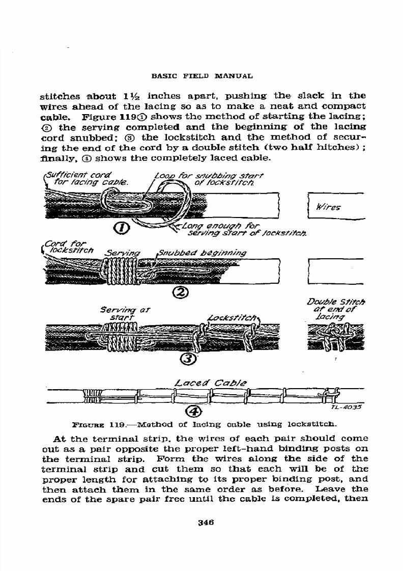
8/16/2019 (1942) FM 24-5 Signal Communication
http://slidepdf.com/reader/full/1942-fm-24-5-signal-communication 350/383
BASIC
FIELD
MANUAL
stitches
about
11/2
inches
apart,
pushing
the
slack
in
the
wires
ahead
of the
lacing
so as
to make
a
neat
and
compact
cable.
Figure
1190
shows
the
method
of
starting
the
lacing;
(
the
serving
completed
and
the beginning
of
the
lacing
cord snubbed;
®
the lockstitch
and
the
method
of secur-
ing
the end
of
the cord
by
a
double
stitch
(two
half
hitches);
finally,
( shows
the
completely
laced
cable.
cietord
0loo,0
for
s/lbb/i7;
start
for /acing
cab/e.
of
locstitc/,
_ (Dsy'
~
~
+es
CI)
Z--o--
Lon; enoagh
for
x' seryJrng
start
of /oc'st/Yc4
Doubl/e
5titch
Serving
ar
at
er of
start
Zockstitch~
/aci)ng
¡Laced
Cabl/e
FIGURE
119.-Method
of
lacing
cable using
lockstitch.
At
the
terminal
strip,
the
wires
of
each
pair
should
come
out
as
a
pair opposite
the
proper
left-hand
binding
posts
on
the
terminal
strip.
Form
the
wires
along
the
side
of the
terminal
strip and
cut
them
so that
each
will
be
of
the
proper
length
for
attaching
to its
proper
binding
post,
and
then
attach
them
in
the
same order
as before.
Leave
the
ends
of the
spare
pair free
until the cable
is
completed,
then
346
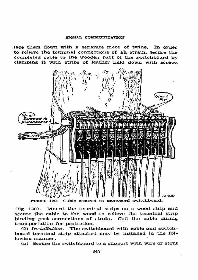
8/16/2019 (1942) FM 24-5 Signal Communication
http://slidepdf.com/reader/full/1942-fm-24-5-signal-communication 351/383
SIGNAL COMMUNICATION
lace
them down with
a
separate
piece
of
twine.
In
order
to relieve the terminal connections
of
all
strain,
secure the
completed
cable to the wooden
part
of
the switchboard by
clamping
it
with
strips
of
leather
held
down
with
screws
iGuRE
120.-Cable secured.
(fig.
120).
Mount
the
terminal strips
on
a
wood
strip
and
secure the cable to the wood to relieve the terminal strip
binding
post connections
of
strain.
Coil the cable during
transportation
for protection.
(2) Installation.-The
switchboard with cable and
switch-
board terminal
strip attached
may
be
installed
in the fol-
lowing
manner:
(a)
Secure
the
switchboard
to a
support
with
wire
or stout
347

8/16/2019 (1942) FM 24-5 Signal Communication
http://slidepdf.com/reader/full/1942-fm-24-5-signal-communication 352/383
BASIC
FIELD
MANUAL
cord.
Do
not drive
nails
through
any
part
of
the
frame.
The
switchboard
should
tilt slightly
forward
to
permit
the
shutters
to
fall
when
released,
and
the
plugs
must not
touch
the
ground
(fig.
121).
(b)
Install
the
switchboard
terminal
strip
out
of
the
way
(e)
Connect
the operatorsOpltpoh
Tth
hor
011 0rou
id
IGnURE
121.-Installation
of
monocord
switchboard.
of
the
operator,
but
conveniently
placed
for
maintenance
personnel
to work
thereat.
Route
the
cable
from
the
switch-
board
to the
terminal
strip
so
as to
afford
protection
to
the
wires
('fg.
122).
(c)
Connect
the
operator's
telephone
to the
spring
clip
terminals
on
the
switchboard
marked
Ll
and
L2. Connect
a
low
resistance
buzzer
or bell
as
a night
alarm
across
the
348

8/16/2019 (1942) FM 24-5 Signal Communication
http://slidepdf.com/reader/full/1942-fm-24-5-signal-communication 353/383
SIGNAL
COMMUNICATION
terminals
marked
A
and
Ai
and
a dry
battery
for
operating
the
night
alarm
across
terminals
marked
B
and
Bi.
Connect
a
wire
from
the
terminal
marked
G
to
a
suitable
metal
ground
rod
or
stake
driven
in the
ground
near
the
switchboard
(par.
siio
s,*
28).
Release
the shutter s of
the
--
units
which are to be used
Write
with
a lead
pencil
the
designation
of
the
directory
names
and
numbers
on the
small
celluloid
strips on
each
switchboard
line
unit.
(3)
Preliminary
tests.-(a)
Turn
the
generator
crank
of
556773-43
.-
3
349
56773°-43
23
349

8/16/2019 (1942) FM 24-5 Signal Communication
http://slidepdf.com/reader/full/1942-fm-24-5-signal-communication 354/383
BASIC
FIELD MANUAL
the operator's telephone rapidly for several turns.
It
should
turn easily.
(b) Short-circuit
the tip
and sleeve of the operator's
plug
and
again
turn
the
generator crank.
It should
turn
hard.
(e)
See that
two serviceable fuses are installed in the spring
clips
at
the
top
of each switchboard unit.
Hold
the
operator's
plug
between the
line
terminal
binding posts
of
the
first unit
so
that
the
tip
makes
contact with one binding post and the
sleeve
with the
other.
Turn
the
generator crank
of
the
tele-
phone. The shutter
of
th¿
unit should
fall
and
the
night
alarm
bell
or
buzzer
should
operate. Restoring
the
shutter
should stop
the
alarm.
(d) Insert the operator's plug
in
the jack of
the
first unit
and
turn the generator crank.
It
should turn
easily.
Short-
circuit the
line terminals
of
the
unit
and again turn
the
generator crank; It should turn hard,
but
the
shutter should
not fall in either case.
(e)
Remove the short
circuit from
the
line terminals
of
the
unit. Short-circuit
the
tip
and
sleeve
of
the
plug
of
the
unit
and
turn the generator
crank.
It
should
turn hard and
the drop
should
not fall.
(f) Test each
unit
in
the
same manner as above. If any
one
of
the above tests
fails,
replace
the
faulty unit or turn
the
switchboard
in
for
repair.
(4) Installation
in
parallel.-Two
monocord
switchboards
may
be connected
in
parallel if one
is insufficient for
the
num-
ber
of
circuits.
The installation
is
made
as
follows:
(a) Install the
first switchboard
as prescribed in
(2)
above,
leaving
sufficient space between the switchboard and opera-
tor's telephone
to mount
the added switchboard to
the
right-
hand side
of the first. Installation
is
the
same, except
that
only certain terminals are connected and these are
connected
in parallel
to
the
corresponding terminals
on the first
switch-
board
as
shown
in
figure
123;
connect terminals
A,
to
A,
and
B.
to
B.;
and
if the
operator's
cord
on the
first switchboard
is
not
sufficiently long to
reach
all units on
the
additional
switchboard connect terminals Li to
Li and
L2
to L2.
To
ground
the switchboards, connect G
to
G and
ground one
of
the terminals.
(b)
When
the
switchboards
connected
in parallel are
in-
350

8/16/2019 (1942) FM 24-5 Signal Communication
http://slidepdf.com/reader/full/1942-fm-24-5-signal-communication 355/383
SIGNAL COMMUNICATION
stalled
in
a
manner
which
prohibits
the
plugging
in of
any
line
unit
cord
in
all
of the
other
line
jacks,
full
use
may
be
made
of the switchboards
by
trunking
the switchboards
together.
This
is
accomplished
by
reserving
for
trunking
one or more
line
units
on the
right-hand
side
of the
left-hand
switchboard
and
a
like
number
of
line units
on the left-hand
side
of
the
right-hand
switchboard.
Plug
the
cord
of
the
line
unit
of
the
left-hand
switchboard
into
the
jack
of
the
line unit
of the
right-hand
switchboard
and
leave
this con-
NJGHT BELL
A
A.
G
A A
O
MONOCORD MONOCORD
OPERATORS
SWITCHBOARD
SWITCHBOARD
TELEPHONE
NO.I 1
NO.2
B 8x
L L
B
B L
L
BROKEN
LINES
SHOW
CONNECTiONS
TO
SE
MADE
WHEN THE
OP-
1
_____
___=_ERATOWS
CORD
ON
--------
SWITCHBOARD
O.I
WILL NOT
REACH ALL
UNITS ON
SWITCH-
BOARD
NO.
2.
TL-842
FIGTIm
123.-Parallel
connection
oi monocord
switchboards.
nection
up
throughout
the
operation
of
the
switchboards
in
parallel.
Any
connection
to be
made
between
the
switch-
boards
where
the
line
unit
cords
will
not
reach
may
be made
through
these
two
line
units
which
are
trunked
together.
(5)
Operatioon-(a)
An
incoming
call is
indicated
by
the
falling
of the shutter
of the
calling
line.
Insert
the operator's
plug
into
the
calling
party's
jack.
After
determining
the
party
(or
central)
to
be called,
remove
the
operator's
plug
and
insert
it in
the
called
party's
jack.
Ring
the
called party
by turning
the
generator
crank
of
the
operator's
telephone
351

8/16/2019 (1942) FM 24-5 Signal Communication
http://slidepdf.com/reader/full/1942-fm-24-5-signal-communication 356/383
BASIC FIELD MANUAL
and
then insert
the called party's
plug into
the calling
party's
jack.
In the case
of
a
trunk
call,
do
not insert
the
called
party's plug
in
the calling
party's
jack
until after
the num-
ber
has
been
passed
to
the distant
operator.
The
operator's
plug may
be left in the
called party's
jack until
the
conversa-
tion
has actually
begun, or
until
it
is necessary
to answer
another call.
When the
conversation
has actually
begun,
remove
the operator's
plug
and restore
the
shutter.
In case
it is necessary
to answer
another
call
before the
first
con-
nection
has
been
properly
supervised,
do not restore
the
shutter
until
the
first
connection
has
been supervised.
(b) When the
conversation
is
completed
and either
party
rings
off, the
called party's
shutter
will
fall. Insert
the op-
erator's
plug into
the called
party's jack
and answer
the
signal
to see
if either
party
desires
another
connection.
Ii
no
reply
is
received,
take the connection
down and
restore the
shutter.
(c)
The
operation
of
two switchboards
in
parallel is
the
same as the
operation
of
a
single switchboard,
one
operator's
set
being used
for both
switchboards.
(d)
When
two
parties
desire
a straight-through
connec-
tion
so
that
either
party
can ring
the
other
without
operating
the
shutters
or requiring
the
services
of
the
operator,
the
units may
be cross-patched, that is,
the plug of
one
unit
in-
serted
in
the
jack of
the other
and
vice
versa.
Such
connec-
tions
are
not
established
except
as
directed
by
the
signal or
communication
officer.
This action
disconnects
both
drops
from the
circuit
and provides
a direct
connection between
the
two
lines.
Since neither
party
is then
able to signal
the
operator,
the latter
should
be informed
as
to
how long the
through
connection
is desired.
(6)
Conference
call.-(a)
Inform the
calling
party
that
he
will be
called when
all
parties
are
on
the
line.
(b) Ring the
first
of the
called parties
and
when
he
answers
request
him.
to
hold the line
for a conference
call,
telling
him
what
party
is calling.
(c)
Ring
the second
called party
and when
he answers
re-
quest
him also
to hold the
line
for
a conference
call.
Then
plug
the
first
called
party's
plug
into the
second called
party's
jack.
Extend the
connection
in a similar
manner to
each
of
the
called
parties
in turn.
352

8/16/2019 (1942) FM 24-5 Signal Communication
http://slidepdf.com/reader/full/1942-fm-24-5-signal-communication 357/383
SIGNAL
COMMUNICATION
(d) When the last
of
the
called
parties
has been connected,
ring
the calling
party
if he is
not
already on
the
line. Inform
the calling party
that all parties are now on the
line, then
plug
the
calling party's plug into
the
first
called
party's jack
and tell the calling party
to
go ahead.
(e) When
the
conversation
has begun, remove the oper-
ator's plug
from
the
calling
party's
jack
and
restore
his
shutter. All parties
are
now
connected and each can
talk
or
listen
to
any
of the
others.
The callinc party's
drop
remains
bridged
across
the connection
for a supervisory
signal. The
connection
may
be
supervised
by
plugging
into
the
calling
party's jack.
d. Telephone centraloffice set TC-4.-The
telephone cen-
tral
office
set TC-4
is
used at
division
and other
headquarters
requiring a
switching
central of the
capacity
of this equip-
ment.
The principal equipment comprises
a
switchboard
BD-96 and a
panel
BD-97.
(For
a complete
description
see
TM 11-332.)
(1)
Switchboard
BD-96.-The
switchboard is
a
complete
transportable single position,
manually operated telephone
switchboard for
serving
magneto-line traffic as well as
origi-
nating
and terminating trunk-line and
tie-line
traffic.
The
switchboard
comprises
40
line circuits,
magneto;.
12 cord cir-
cuits; 4 common battery
trunk
circuits, manual
and auto-
matic; 1 first operator's
telephone circuit
with grouping key;
1
ringing
circuit;
1
conference
circuit;
1
dial
cord
circuit;
1
second
operator's circuit; and
1 night alarm
circuit. In
operating
position the
approximate
size of
the
switchboard
is 15
inches
deep by 22
inches
wide by
47 inches
high. (See
fig.
124.)
The
switchboard
is arranged to be
packed
within
the
angle
iron
base;
therefore,
no additional
packing
case
is
necessary
for transportation.
(2) Panel BD-97.-The panel is arranged
as
shown in
figure
125.
It
comprises
eight
repeating
coils C-161
mounted four
on each
side
of the cabinet;
two terminal
strips of 44
binding
posts each
mounted on
each
side
of
the
cabinet;
two verti-
cal rows of
22
pairs of
1-ampere
fuses
and
unit dischargers
mounted in the center of the cabinet; and
three
rubber
covered
cables
of 15
pairs
each 21 feet
long
for interconnecting
the panel BD-97
with
the switchboard BD-96. In operating
353

8/16/2019 (1942) FM 24-5 Signal Communication
http://slidepdf.com/reader/full/1942-fm-24-5-signal-communication 358/383
BASIC
FIELD
MANUAL
position
the size
of
the panel
is
approximately
11
inches
deep
by
241/2
inches wide by
55 inches
high.
(See
fig. 125.)
A
separate
packing
case
is
not
necessary
for
transportation
of
the panel.
(3)
Installation.-Turn
the
switchboard
and base
upside
IG1JRE
124.-Switchboard
BD-96
set
up
for
operation.
down,
remove
the seat
top,
and
extend the extension legs
of the
base. Ease the equipment
to an upright
position
and
lift
the
base
off
the
switchboard,
setting
it in
the desired
position for the
switchboard.
Set the switchboard
on
the
base making
sure that the
dowels in the
base
of
the
switch-
board
engage the
holes
in the
top of
the base.
Unfasten
the
354

8/16/2019 (1942) FM 24-5 Signal Communication
http://slidepdf.com/reader/full/1942-fm-24-5-signal-communication 359/383
SIGNAL
COMMUNICATION
cord
compartment
allowing
the
cords and
weights
to drop
into
position.
Clamp
the
switchboard
to the
base
by means
of
the
two wing-nut
bolts
provided.
Remove
the front cover
of the
/ii~~~~~~~~~~~~ ~~~o
FIGURE
125.-Panel
BD-97
ready
for
operation.
355

8/16/2019 (1942) FM 24-5 Signal Communication
http://slidepdf.com/reader/full/1942-fm-24-5-signal-communication 360/383
BASIC FIELD MANUAL
switchboard
and raise the
designation
strips permitting the
drops to fall. Fasten the seat top to the switchboard cover
for an operator's chair.
Install
six
batteries
BA-30
in
the
compartment in
the
lower
rear
of
the
switchboard.
(When
more
than one
switchboard
is
in
use, set up the additional
units
successively adjacent to the
first unit
in a similar man-
ner to
that
just described.)
Set
the
panel
BD-97 in a suitable
location
within
cabling distance of
the
switchboard. Loosen
the bars
on
the
outside of the case and raise the
upper
half of
the
panel (the
half without the handles)
until it is vertical.
Pasten
the
two
lower
bars
of
the
upper
cabinet to
the
top
bolts
of
the
lower cabinet as a brace.
Unstrap
the
cables
and
remove
the two angle irons chained to the panel; fasten these
angle
irons
to
the
bottom of the
lower cabinet
to form extension
legs. Slots are provided in the angle
irons
to provide
for
mounting
the
panel BD-97 either
at
the center
or
at the end
of the angle irons permitting installation
against
a wall.
The upper cabinet may
be
removed
and
suspended
on a
wall
by
means
of
hangers
at
each corner.
The ringing
machine
may
also be removed.
Connect
the
three
cables
to
the three
rows of binding posts in
the
top of the
switchboard
as
desig-
nated. (Local battery
trunk circuits
should be terminated
in
line jacks.) Install the
ground rod
and
connect it
to
the
ground
terminal of
the BD-97.
Connect
the incoming lines
to the binding posts in the upper
cabinet, wiring through the
repeating
coils
when desired.
When a
110-volt, 60-cycle
power source is available, plug in the power cord of the ringing
source
into a convenient
outlet
and
extend
ringing
current to
the switchboard by means of cord CD-451. The
switchboard
termination
for ringing power is located
on the
panel
in
the
top
of the
switchboard.
(4) Operation.-Operation
of this
switchboard
is
charac-
teristic of comparable commercial switchboard practice.
The
drop
signals
indicate
a
call
on
a
line
or
trunk.
When
a
call is
received
as
indicated by the drop, the
answering plug
(back plug) is inserted
in
the jack associated with the
signal
(the
drop
is
mechanically
restored
to
normal
position
by the
insertion of the plug) and
the
operator's
circuit
is
connected
by operating
the
key
immediately
in
front
of
the
cord
circuit
used
to
the
locking
position
(away
from
the
operator).
To
356

8/16/2019 (1942) FM 24-5 Signal Communication
http://slidepdf.com/reader/full/1942-fm-24-5-signal-communication 361/383
SIGNAL
COMMUNICATION
call a
number,
insert the
calling plug (front plug)
in
the
desired party's line
jack and
operate the key
immediately in
front
of
the cord
circuit used to the nonlocking ringing
posi-
tion
(toward
the
operator).
Supervision
of
a
call
is
provided
by a row
of drops located immediately above
and directly
associated
with each cord circuit. Ring
off
or
recall
is
indi-
cated by
these drops falling.
An audible
night-alarm
circuit
is
associated
with all drops
at
the
option
of
the
operator
by
a night-alarm key
located
at the upper
left
of the face
panel.
A grouping key is provided so that
an
operator
may
use the
cord
circuits
of
an adjacent
switchboard where
two
or more
boards
are
set
up together.
To
connect
a telephone
to
a
dial
exchange, use any cord circuit to connect
the telephone line
jack to
the
trunk-line
jack
(engraved L) of
the
trunk desired.
When
the operator hears
dial
tone,
he
plugs
the dial
cord
into
the
adjacent dial
jack
(engraved
D)
and proceeds
to dial
the
desired number.
When ringing
is heard, the operator
re-
moves
the
dial plug from
the dial jack. To connect a tele-
phone
to a
common
battery
manual
exchange,
use
any
cord
circuit to
connect the telephone-line
jack
to the
trunk-line
jack desired. Plugging in signals the distant
operator. An
incoming call
on a
trunk
line is answered the same as any
other call.
To
connect
a
number
of lines together for
confer-
ence,
the
answering
cord plug
is
inserted
in the
line jack
of
the party
originating
the
conference
call.
The associated
calling plug
is
then inserted in one of
the
six
conference call
jacks. The
other
connections
to
the
conference
are
made
by inserting
the
answering
cord
plugs in one of the
conference
circuit
jacks
and the
associated calling
plug
in
the line
jack
of the desired
party
to
be
called.
The operator
must
call each
member
of
the conference
in
the usual
manner.
During peak
traffic
loads, provision
is
made for
the
use of
an
additional
operator by
operating the
key
at the
lower left-hand
corner
of
the
switchboard panel
face.
This
places cord
circuits
9
through
12
on external
terminals
with provision
for
connect-
ing
any
local battery
telephone
to the switchboard
for
use
of
the second operator.
U 4. "IELD
TELEGRAPH SETS-.-4.
Telegraph
set TG-5-A.-The
telegraph
set
TG-5-A
is
shown
in
figure 126 and
is
described
357

8/16/2019 (1942) FM 24-5 Signal Communication
http://slidepdf.com/reader/full/1942-fm-24-5-signal-communication 362/383
BASIC FIELD
~ANUAL
)
i,
a
3 8M.
358

8/16/2019 (1942) FM 24-5 Signal Communication
http://slidepdf.com/reader/full/1942-fm-24-5-signal-communication 363/383
SIGNAL
COMMUNICATION
completely
in
TM
11-351.
Two
batteries
BA-30
and
one
bat-
tery
BA-2
are
required
for
operation.
The
line
battery
BA-2
is
carried
in
the
line battery
cup
and
the
batteries
BA-30
are
contained
inside
the
local
battery compartment in
the rear
of the
set.
(See
figure
127.)
The
large
binding
posts
Li and
L2
are
the
line
connections,
whether
for
simplex
to ground,
or
for
full
metallic
circuit.
Basically
the circuits
of the
tele-
graph
set TG-5-A
can
be
divided
into
the
line
circuit
and
the
local
circuit.
The
line circuit
comprises
the
22.5-volt
line
battery,
the
telegraph
key
and
the
line
relay,
all
in series;
it
is
connected
by
the
field wire line
to
the
identical
equipment
in
the distant
stations
comprising
the
net.
The
telegraph
keys have
three
terminals,
and
the
circuits
are
such
that
when
the key
is
up, the
circuit
is
completed
through
the
back
con-
tact.
Depressing
any key
in
the
telegraph
net
places
a
22.5-
volt
battery
in
series
with
the
line,
causing
all
the
line
relays
to
operate.
The
local
circuit
has
two
functions;
it
can
oper-
ate
as
an
alarm,
in
which
case
ringing
of the
bell
in
the
telegraph set indicates
that
a station in the
net
is
beginning
operation;
or
it can
key
a
tone
from
a hummer
(telephone
receiver
direct-coupled
to a
carbon-button
microphone)
for
Morse
code
communication.
(1)
Installation.-Remove
the telegraph
set
from
its carry-
ing
case,
and
open the
front
compartment,
removing
the
headset
and
cord.
Open
the local
battery
compartment
by
turning
the
slot
on
the
catch
to
a
vertical
position
by
means
of
a screw
driver.
Place
two
fresh
batteries
BA-30
in the
local
battery
compartment,
making
certain
that
the
case
of
one
battery
makes
contact
to
the
coiled
spring
and
that
the
cap
of the
other
battery
makes
firm
contact
to
the
metal
spring
plate
which
should
be
clean
and
bright.
The
contact
between
the
batteries
should
likewise
be
clean.
Close
and
lock
the
door
of
the
local
battery
compartment.
Should the
alarm
bell
ring, set
the
SPRING
and
the
GAP
pointers
on
the
relay
at
zero,
then
increase
the SPRING
pointer
setting
one
notch at
a time
until
the ringing
ceases.
Adjust
the
key
until
its
"feel"
is suitable
to
the
touch.
Be
certain
that
the
front
contacts
are
open
when
the
key
is
released,
otherwise
the
line
battery
will
be
short-circuited
and
the
key
contacts
may
also
be ruined.
Connect
the
red
lead
of
the
359

8/16/2019 (1942) FM 24-5 Signal Communication
http://slidepdf.com/reader/full/1942-fm-24-5-signal-communication 364/383
BASIC FIELD MANUAL
22.5-volt
battery
BA-2 to the
small
plus
(+)
binding
post
and the black lead to the 22-volt negative (-22) binding
post.
Connect the
telegraph
lines
(or telegraph
leg
of
re-
peating
coil
and ground of simplex
circuit)
to
Li
and
L2.
(2)
Adjustment
and test.-(a) Alarm circuit.--Short-
circuit
the binding
posts Li and L2. Depressing the tele-
graph key should
start
the alarm bell ringing. If the alarm
2.fteeriesB
l oAl
at0
53
PIGuw.
127.-Telegraph set
TGO-5-A,
showing the
local
battery com-
partment and batteries BA-30.
fails
to ring,
and
the battery BA-2
is known
to be service-
able
and
properly
connected,
move the GAP
pointer setting
one
notch
at
a
time
beginning
with
zero
until
the
bell
rings
when the key
is
depressed. If
the bell continues to ring upon
releasing
the
key,
increase the SPRING pointer setting
one
notch
at
a time until the alarm stops ringing.
(b) Local tone circuit.-Insert the plug in
the
jack at the
lower
right-hand
corner
of
the
set. This closes
the local
battery circuit to the
hummer,
and
a faint
hum
may be
heard continuously,
indicating the hummer is working.
De-
360
8/16/2019 (1942) FM 24-5 Signal Communication
http://slidepdf.com/reader/full/1942-fm-24-5-signal-communication 365/383
SIGNAL
COMMUNICATION
press
the
telegraph
key
(with
the
line binding
posts
still
short-circuited).
A
1,000-cycle-per-second
tone
should
be
heard
clearly.
The set
box must
be
in an upright
position
as
this
is
necessary
for
the
best
operation
of
the hummer.
The
short
circuit
should
now be
removed
and
the
relay
may
now
be adjusted
for operation
in Ihe
telegraph
circuit.
(C)
Line
relay
adjustment.-Considerable
care
is
required
to
adjust
the
line
relay
for
satisfactory
functioning
on
cir-
cuits
of
varying
line
length
and ground
connection
resist-
ance.
When the
SPRING
and
GAP
pointers
are
at
zero,
the
armature
air-gap
is
smallest and
the
spring tension
]east.
Under
these
conditions,
the
relay will
operate
with small
currents.
Due to
the characteristics
of the
relay,
this
adjust-
ment
will
not be
satisfactory
for
relatively
larger
currents,
as
the
spring
adjustment
will
be too
weak
to pull
the arma-
ture
sufficiently
quick
after the
larger
currents
cease
to flow.
The adjustment
consists
in
properly
balancing
the spring
tension
against
the
magnetic
pull when
current
flows
in
the
relay
winding.
Best
adjustments
are obtained with
the
low-
est
setting
of the GAP
pointer
which
will permit
the
relay
to operate
with
the
current
from the
most
distant set,
and
the
lowest
setting
of
the
SPRING
pointer
which
will open
the
relay
contacts
sharply.
Proper
adjustment
of the
relay
is obtained
when
the tone
in
the
telephone
headset
clearly
and
accurately
follows
the
telegraph
keying,
and
shows
no
tendency
to
lag
or
stick
on
dashes
or to chirp on
dots.
(3)
Operating
the set.-(a)
Transmitting.-Use
the
key
as in
any other
telegraphic
circuit;
continuous
monitoring
of the
transmission
is
always
present.
The
line
battery
BA-2
furnishes
current
only
when
the telegraph
key
is de-
pressed.
(b)
Receiving.-With
the relay
properly
adjusted,
the
transmissions
from
the
distant
station
are
as loud
as the
local
signals,
since
the
hummer circuit furnishes
the
tone
for both.
(c)
Break-in.-If
it
is
desired
to
break
in
on
the trans-
mission
of
the
distant
operator,
operate
the
telegraph
key
of the
local set,
making long
dashes.
The distant
operator
will
immediately
be
aware
of
the break-in
signals and
stand
by
for the local
operator's
transmission.
(d) Continuous
operation.-If
the set
is
to
be
operated con-
361

8/16/2019 (1942) FM 24-5 Signal Communication
http://slidepdf.com/reader/full/1942-fm-24-5-signal-communication 366/383
BASIC FIELD MANUAL
tinuously, keep the plug in the jack. Signals are then re-
ceived
only
in the headset which must be worn in order not
to
miss a
call.
Such
operation
causes
a
continuous
drain
on
the local batteries.
(e)
Stand-by
operation.-With the plug withdrawn
from
the jack,
the
hummer is inoperative, and
incoming
signals
operate
the alarm
bell. No battery
drain
exists
in such
case
except
when the
alarm
is
ringing. This is desirable for
stand-by operation .
(4)
Care
of telegraph set TG-5-A.-ICeep the telegraph set
TG-5-A
clean
and
dry,
blowing
out
all
dust
or
dirt
picked
up in the
field.
Keep
all
connections tight, and inspect
the
wiring
for broken
leads.
The local battery coiled-spring and
plate contacts should
be
clean
and
bright. The
telegraph key
contacts and
the
relay contacts should be
kept
clean.
This
is
done
by
placing
a
small
piece
of glazed
paper which has
been
dipped
in
carbon tetrachloride between the contacts and
withdrawing
the
paper with
slight pressure on
the
contacts.
Repeat
with
a piece of dry
paper, always
taking
pains
to
prevent
lint
from accumulating on the contacts. Should
the
contacts
be
pitted,
it
may be necessary to
use the burnisher
furnished with
each set.
This
is done by placing the
thin
blade between
the
contacts
and withdrawing
it
with
a slight
pressure
on the contacts.
Especial
care must be taken
in
burnishing
the relay contacts not to spread or bend
the
springs
apart,
as
this
will
cause
faulty
operation.
As
with
all
other apparatus,
remove all
the
batteries
from the tele-
graph set if
it
is not to be kept in continuous service.
b.
Telegraph
set
TG-5.-The telegraph set TG-5
is de-
scribed in TM 11-351.
*5. DRY BATTERIES.--a. General.-Dry batteries are the
principal
source
of power for field wire equipment.
Since
weak
or
run-down
batteries
render
such
equipment
inoper-
ative, they are
always
suspected
as
the
cause
of trouble when
equipment
in
which
batteries
are
installed begins to
decrease
in
efficiency. Dry batteries
deteriorate rapidly when
in
use,
and
slowly
when
in
storage. The date of manufacture is
ordinarily
stamped
on
dry
batteries and aids in estimating
the probable capabilities of dry batteries either in
stock
for
issue
or
in
use.
362
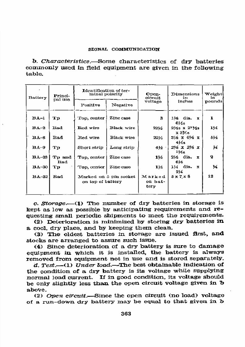
8/16/2019 (1942) FM 24-5 Signal Communication
http://slidepdf.com/reader/full/1942-fm-24-5-signal-communication 367/383
SIGNAL
COMMUNICATION
b.
Characteristics.-Some
characteristics
of dry
batteries
commonly used
in fleld
equipment
are
given in the
following
table.
Identification of
ter-
Princ.i-
minal polarity
Open-
Dimensions
Weight
Battery
___-
circuit
in
in
Battery pal ause
-
voltage inches punds
Positive
Negative
BA-1
Tp Top,
center
Zinc
case
3
19H
dia. x
1
634
BA-2
Rad Red wire
Black
wire
2234 232
x
213i
l14
x 3M6
BA-8
Rad
Red wire
Black
wire
22¼ 3Ys x 634
x
63
4M46
BA-9
Tp Short strip
Long
strip 44 -
2% x 234 x
3
BA-23 Tp
and Top,
center
Zinc
case 114 23
dia.
x
2
Rad
634
BA-30
Tp
Top, center
Zinc case
134 134 dia.
x
Y
234
BA-32
Rad Marked
on 5pinsocket
Marked
5x7tx8 12
on top
of
battery on
bat-
tery
c.
Storage--(1)
The
number
of
dry batteries
in storage
is
kept
as
low
as possible
by
anticipating
requirements
and
re-
questing small
periodic
shipments
to
meet the
requirements.
(2)
Deterioration
is minimized by
storing
dry
batteries
in
a
cool,
dry place,
and
by
keeping
them
clean.
(3)
The oldest
batteries
in storage
are
issued
flrst,
and
stocks
are
arranged
to assure such
issue.
(4)
Since
deterioration
of
a
dry
battery
is
sure
to
damage
equipment
in
which
it
is installed,
the
battery
is
always
removed
from
equipment
not
in use
and is
stored
separately.
d.
Test.-(1)
Under
load.-The
best
obtainable indication
of
the
condition
of
a
dry
battery
is its
voltage
while
supplying
normal
load
current. If
in good
condition,
its
voltage
should
be
only slightly
less
than
the
open circuit
voltage
given
in b
above.
(2)
Open circuit.-Since
the
open
circuit (no load) voltage
of a
run-down
dry
battery
may
be equal
to that
given
in b
363

8/16/2019 (1942) FM 24-5 Signal Communication
http://slidepdf.com/reader/full/1942-fm-24-5-signal-communication 368/383
BASIC
FIELD MANUAL
above, measuring
the voltage of a
battery
when it is
not
supplying
load
current
may in
some
cases give
little indica-
tion of
its
condition.
Nevertheless, this voltage
may be meas-
ured
as
a
matter
of
routine
before
a
battery
is
installed,
because if
the open
circuit voltage is less than
90
per cent
of
that
given
in
b above, the battery
is
practically useless,
as
will be otherwise
evident from the fact that
the apparatus
will not function properly.
The
"tongue-test"
method
which
is
frequently used for estimating
the
condition
of
a low-
voltage
battery,
performed by
placing the
battery
terminals
on
the
tongue,
is
worthless
as
a measure
of
a
battery's
condition.
364
8/16/2019 (1942) FM 24-5 Signal Communication
http://slidepdf.com/reader/full/1942-fm-24-5-signal-communication 369/383
APPENDIX
II
LIST
OF REFERENCES
·
1.
FIELD MANUALS.
Mission, Functions
and Signal
Communication
in
General________________________________
FM 11-5
Organization
and
Operations
in
Infantry
Divi-
sions----____--
__--
___________ ____________ FM
11-10
Organizations and
Operations
in the Cavalry
Division
and Cavalry
Corps----_____._____-__
FM
11-15
Signal
Organizations and Operations in
the
Armored
Division and
the
Armored Corps
__.
FM
11-17
Organizations
and
Operations
in
the
Corps,
Army,
Theater
of
Operations,
and
GHQ______
FM
11-20,
Signal
Corps
Intelligence------_______________
FM
11-35
List
of
Publications for
Training -_____________
FM
21-6
Conventional
Signs, Military
Symbols,
and Ab-
breviations __-----_-------- -
-__-______--___
M
21-30
Radio 'Procedure -----__--------_____________
FM 24-6
Joint
Army
and
Navy
Radio
Procedure________
FM
24-10
Operations
-_--------_--_--------__
--
------
FM 100-5
Administration
------------------------------
FM
100-10
The Staff
and Combat Orders -----
____-----
__ FM
101-5
Organization,
Technical
and
Logistical
Data--__
FM
101-10
* 2. TECHNICAL MANUALS
AND
TECHNICAL
REGULATIONS.
Electrical
Fundamentals ---._--______________
TM 1-455
Radio Sets
SCR-178
and
SCR-179-__--------_
TM
11-231
Radio Set
SCR-177-B------------------------
TM 11-232
Radio Sets SCR-131
and
SCR-161_____________
TM
11-237
Radio Sets
SCR-194
and SCR-195________-____.
TM
11-238
Radio
Set SCR-203---_-
-----------
-__ -_-__ M
11-239
Radio
Sets SCR-210-A,
-B, -C, -D,
-E, -F, -G,
-H and -J
and
Radio
Sets SCR-245-A,
-B, -C,
-D, -E, -F, -G,
-H, -J, -K, -L, -M,
-N,
and -P_
TM 11-272
556773-43- 24
365
8/16/2019 (1942) FM 24-5 Signal Communication
http://slidepdf.com/reader/full/1942-fm-24-5-signal-communication 370/383
BASIC
FIELD
MANUAL
Radio
Sets
SCR-193-A,
SCR-193-B,
SCR-193-C,
SCR-193-D,
and SCR-193-E_____-________--
TM
11-273
Frequency
Meter
Sets
SCR-211-A,
SCR-211-B,
and
SCR-211-C--------------=------------
TM
11-300
Charging
Set
SCR-169----__------------------
TM
il-402
Switchboards
BD-71
and
BD-72 --------------
TM 11-330
Switchboard
BD-14_------_------------------
TM
11-331
Signal
Corps
Telephones
EE-8-A___-----------
TM 11-333
Telegraph
Set
TG-5 and
TG-5-A
---.---------
TM
11-351
Installation
and
Maintenance
of
Telegraph
Printer
Equipment-
-----------------------
TM
11-353
Reel
Unit
RL-26
and
RL-26-A_______________-
TM
11-360
Signal Corps Test
Set
EE-65
and EE-65-A
_____
TM
11-361
ReeI
Unit
RL-31_---------------------------
TM 11-362
Converter
M-209
----------------------------
TM
11-380
The Homing
Pigeon
------------------------
TM
11-410
Tables of
Vertical
and Horizontal
Components
of
Distances
of
Pilot
Balloons
---------------
TM
11-420
Storage
Batteries
for Signal
Communication
Ex-
cept
Those
Pertaining
to
Aircraft-___----__-
TM
11-430
Target Range
Communication
Systems____-___
T-M 11-431
Code
Practice
Equipment
_-------------------
TM
11-432
Training
of Signal
Communication
Personnel__
TM 11-450
The Radio
Operator--------------------------
TM
11-454
Radio
Fundamentals
-------------------------
TM
11-455
Division
Field
Code,
Training
Edition
No.
2-----
TM
11-460
Air-Ground
Liaison
Code,
Training
Edition
No. 2-------
------------------------------
TM 11-461
Buzzerphone,
Type EE-1-A-------------------
TR
1230-5
1
3.
ARMY
REGULATIONS.
Leather
and
Leather
Equipment__
------------
AR 30-3040
Requisitioning
Property
----------------------
AR
35-6540
Safeguarding Military
Information
-----------
AR
380-5
Military
Motor
Vehicles----------------------
AR 850-15
366

8/16/2019 (1942) FM 24-5 Signal Communication
http://slidepdf.com/reader/full/1942-fm-24-5-signal-communication 371/383
APPENDIX
m
INTERNATIONAL
MORSE
CODE
*
1. INTERNATIONAL
MORSE
CODE.-The
dot
and dask
equiva-
lents
for the International Morse
Code
are as follows:
a.
Alphabet.
A .
J
S
B
K....
_._ T
_
C
..
L
....
U
..
D -.. M
--
V..
E.
N_.
W.
F
_ -O
X
·
G __.
P
..
.
Y
.__
H
....
Q
-- -
Z
.
I
.R.
R
b. Numerals.
1
..---
6
2 ...---
3
....
. 8
4
.....
9
5 .....
O
c. Special
signs-These
are
not used in service
communica-
tions.
a
(German)
.
.
(Spanish)
. _
á (Spanish, Scan-
o
(German)
.
dinavian)
or
a.
-
..
i
(German)
.
.
ch (G
e r m a
n,
Spanish)
367
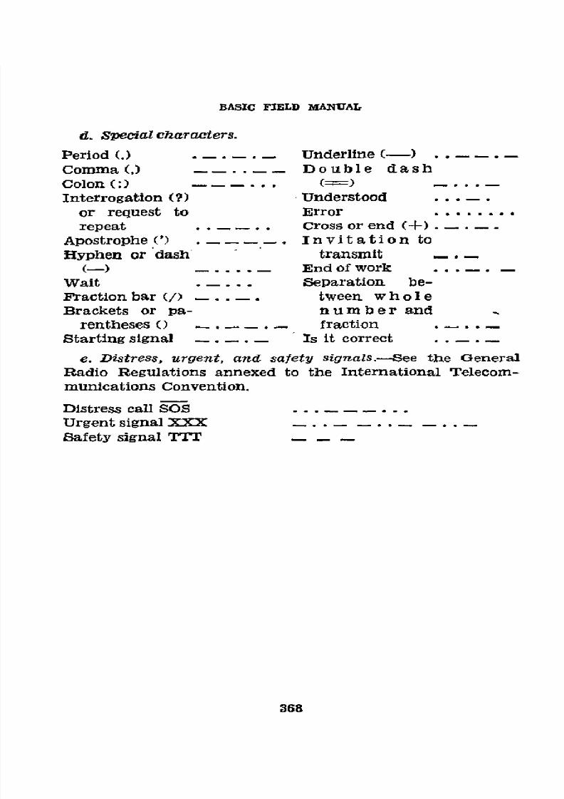
8/16/2019 (1942) FM 24-5 Signal Communication
http://slidepdf.com/reader/full/1942-fm-24-5-signal-communication 372/383
BASIC FIELD
MANUAL
d.
Specialcharacters.
Period (.)
- -.
Underline
(-)
.
.
Comma
(,)
_
. .
Double
dash
Colon (:)
... ()
..
Interrogation
(?)
Understood
. . .
.
or request to
Error
........
repeat
.. .. Cross
or
end (+) . - . -
.
Apostrophe (')
.
_ . Invitat ion to
Hyphen
or dash transmit
_._
(--)
_
...... End of
work ......
Walt
.....
Separation
be-
Fraction
bar
(/) -.. . tween
w h ole
Brackets
or
pa-
number and
rentheses () . -- .. fraction ..
.
Starting signal . - . -
Is
it correct .
. .
e. Distress,
urgent,
and
safety
signals.-See
the
General
Radio Regulations annexed
to the
International
Telecom-
munications
Convention.
Distress
call SOS
.
Urgent
signal
XXX.
.
Safety signal
TTT
- - -
368

8/16/2019 (1942) FM 24-5 Signal Communication
http://slidepdf.com/reader/full/1942-fm-24-5-signal-communication 373/383
INDEX
Paragraph
Page
Abbreviations,
message
center____________________
35
31
Agents -________...............................
71, 81
85,91
Authenticators _________________________________ 32 28
Batteries:
Dry
_________________-_____________________
App.
I
827
Storage
-__________________________________ 251 274
Calls:
Conference__________----______________
177,
App.
I
177,327
Call
signs,
radio, telegraph
and
visual____________
31,
265 28,
290
Cipher
device M-94:
Cryptographing, abbreviations,
punctuation
Cryptographing message____________________59
79
signs,
and
numbers_______________________
60
75
Deoryptographing
message __________________
61 79
Description______-----
_________________-_
56
70
Necessity for
key_--________________________
57 71
Purpose and distribution
_________------____
55
70
Setting
the
device
---------------------
_---- 58
72
Ciphers,
authorized
military--___----_------
_____
53
66
Circuit diagram_____-________________________- 167 262 165, 286
Circuits:
Bridging
simplexed
around
a
switchboard----
229
254
Mutual
interference in simplex
and
phantom
groups
------.
_____--------------------
--- 218
247
Phantom_-______-- __ __--____________---
___ 217
246
Simplex _-________--------_
__---------------
216
245
Code,
International Morse----____--
_--------- App.
III
367
Codes
and ciphers:
Authorized for military use_____------------- 53
66
Comparison
__-_--__
___-_______-__--------_-
52
65
Rules for use-------------------------------
54
68
Colls:
Loading
--------------------------------.---
207
234
Repeating
.-------------------------
15, 216,
217
243,
245, 246
Communication
officer:
Duties -....-________-------
--------------
12 6
Staff and command functions___----------_- 11 6
Conference
calls
_-------------------------------
177 177
Construction center ----------------------------
208
236
Converter
M1-209_---------.....-----------------
62
81
Cryptograms,
use___----------------------------
49
62
Cryptography:
Definitions_____ _--------------------------
50 62
Safety afforded
by_____
- ____--------------
61
65
Definitions:
Cryptography__------5----------------------
50
62
Message
center __-----------------------
...
17
13
Radio
communication__--____---------------
95
110
Signal
communication_______---------------
5 2
Sound
communication
-----------.----------
157
156
Wire communication_---_--------------------
162
158
369

8/16/2019 (1942) FM 24-5 Signal Communication
http://slidepdf.com/reader/full/1942-fm-24-5-signal-communication 374/383
INDEX
Disposition
of
matériel:
Paragraph
Page
Captured
equipment________________________
15
11
Destruction of
matériel____________________
14
9
General
principles__-_______________________
13
8
Responsibility
of
signal
officers
__-------
____
16
12
Fleld wire:
Testing
on
reels
_-------___________________
242,
269
Types
_________________…
---------------
-
184 181
Pleld
wire
lines:
Circuit
troubles__-----______________________
236
257
Construction
and
removal
of
test
stations____..
200
223
Equipment
used
for
testing__________________
237
260
Loading
of
--- __------____________________
207
234
Locating
and
clearing
trouble________________
238 263
Maintenance_______________________________
234
255
Operation
of
test
stations
__________________
239
267
Overhead
construction---____________________
202
226
Patching
circuits
at
test
stations
--
_________
240
268
Patrolling______________________________
241
269
Procedure
in
laying-----____________________
199
206
Railroad
crossings
----
_____________________
204
229
River
crossings
----
_____-_-----__-----------
205
230
Road
crossings______________________________
203
227
Routine
tests____-__________________________
235
256
Routing
__________________-______-_________ 197
220
Surface
construction________________________
201
224
Trench
line
construction
___________________
206
230
,Flags:
Care
---
-
---
_______________----------.-....
132
137
Equipment
-______--_
_______________________
131
136
Semaphore
procedure-______________________
135
137
Training
-----
__-------_____________________
133
137
Use- ------
______
-----__________
-__________
34
137
Wigwag
-___________________________________
136
138
Functions
of
signal
communication___-__________
1
1
Ground
connection
__---________________________
228
253
International
Morse
Code_____________________
App.
III
367
Instructions,
signal
operation_________________
260,
265
284,
290
Lamps:
Adjustment
___________________________-_
124
132
Care
-----
…--a…------------.-.....________
25
133
Equipment
_________-_______________________
123
130
Installation_--________________________ _
127
133
Message
transmission
___________________.--_
129
134
Procedure
---
________--------------------------
130
135
Training
---
________________________________
126
133
Lettering
--------
_----------------_____
33
29
Line
route
map
__________________---_-----___
169,263
167,286
370

8/16/2019 (1942) FM 24-5 Signal Communication
http://slidepdf.com/reader/full/1942-fm-24-5-signal-communication 375/383
INDEX
Message
center:
Paragraph
Page
Abbreviations
__---_----_
__________-________
35
31
Charts,
maps
and diagrams_________________
34
30
Definitions
.-----------------
_
-----________
17
13
Equipment and
forms:
Below
divisions__----_______--
_
_________
45
53
Divisions
and
higher
units__----
_________
37
32
Flexibility
of
organization_____----
__________
21 18
Informal
contact
with
neighboring-_______--
23
20
Organization,
divisions
and higher
units____-
36
31
Principles
of
operation_________-----------
---
24
21
Procedure,
headquarters
below
the
division:
Forms
and equipment-
.----------
____.-
45
General--___---------------------------
43
53
HandIing
messages---_------------------
47
55
Organization
--------
_
---------------
44
53
Records
--
_----------------------------
46
53
Purpose
-----
_-----------------------------
18
13
Records,
headquarters
below
the
division____
46
53
Related
procedures
for
the
electrical
transmis-
sion
of
messages_-------------------------
27
25
Responsibility
-----------------------------
20
17
Training
-----------------------------------
22
19
Messages:
Classification
_____-------------------------
19
14
Dropped messages:
Dropping
grounds
-_______-------------
83
91
Equipment
for
dropping__-----_--------
85
92
Procedure
------------------------------
84
91
Use
------------------------------------
82
91
Handling
of
secret
messages
----------------
41
51
Multiple
distribution
-------
---------------
25
23
Pick-up:
Equipment
-----------------------------
88
95
Field-----------------------------------
87
94
Procedure
------------------------------
89
97
Training
__-----------------------------
90
9'8
Use
------------------------------------
86
94
Preparation
--------------------------------
88
34
Procedure:
Handling
in
lower
units_----------------
47
55
Handling
incoming,
divisions
and
higher
units
.-------------
40
46
Handling
outgoing,
divisions
and
higher
units
--------------------------------
39
87
Handling
relay,
divisions
and
higher
units---_-----------------------------
42
52
Skeleton
copy
----------------------------
39
87
Messenger:
Airplane
------------------------------------
70
85
Basic
training_-----------------------------
66
84
Bicycle
...---------------------------------
69
85
Carrying
messages
--------------------------
75
87
Delivery
of
messages_______--
---------------
76
88
Double
-------------
_----------------------
77
89
Motor
--------------------_----------------
69
85
371

8/16/2019 (1942) FM 24-5 Signal Communication
http://slidepdf.com/reader/full/1942-fm-24-5-signal-communication 376/383

8/16/2019 (1942) FM 24-5 Signal Communication
http://slidepdf.com/reader/full/1942-fm-24-5-signal-communication 377/383
INDEX
Panels-Continued.
Paragraph
Page
Reporting
--------------
____________________
151 149
Special
signals_---_________________________
155
151
Technique
of
display-__.___---
__--
_________
150
148
Phonetic
alphabet_-----_______---
___-----------
178
177
Pigeon
communication,
employment_________-___
91 100
Pigeons:
Delivery,
care, and
use_____-_____----------
92, 252
101,275
Releasing
-_--_-----_--
_________------------
93
102
Transporting
____________-_____________----
-
92 101
Pole
climbing
_________________-______----_
_ _ 193
212
Equipment _______________--___-----------
191
207
Safeguards
___________--_--
___------------- 192
211
Pronunciation
of numerals___
_-----------------.
179
178
Publications relating
to signal
communication_---
4
1
Pyrotechnics:
Care -_____---_----_--------------------
138
142
Equipment
-----------------------------.---
137
140
Signals _-----------_-----------------------
141 143
Training
____________-__-------------------
140
143
Transmission,
message ---------------------
142
143
Use
_____----
_---------------------_---
--
_
139
142
Radio
call
signs
_-----_------------------------
31
28
Radio
communication:
Assignment
of
frequencies and
call signs___--
105
117
Capabilities
__-__---------------------------
97
112
Codes
and
ciphers_________--
____----------
53
66
Cooperation
with
the message
center_____----
110
120
Definitions
-___--_--_----------------------
95
110
Emplpyment
-_-----_----_------------------
96
112
Equipment
--------------------------------
App.
I
327
Procedure,
procedure
signals
and
procedure
signs__----------------______
-____--------
110 120
Radio nets
and
net
control
stations:
Assignment
of frequencies
and
call
signs_
105
117
Control___
__--_-----------------------
102 115
Establishment_________-------------
---
106
117
General____--
________------------------
101
115
Operation_------_---------.-------------
103
116
Regulations,
general
operating_____----
_-----
109
119
Special
uses______-___________--------------
100
114
Station
location ----
_----------------------
99
114
Station records:
Disposition
of records_----------
-------
119
126
Importance-----_----__----------------_
120
126
Operator's
number
sheet_----_----------
115
122
Operator's personal
sign
_______----__--- 956
110
Reception
of messages
___- --
_----------
116
123
Servicing
of messages___--____--
__------
117
123
Station
log____________-_____----------
118
124
Time
entries
and
the
radio
day __----------
113
121
Trafflc
___------_---------
------------------
104 116
Internet__--_________----------------_-
107
118
Training
of
radio
operators____
-
__---
-
98
113
Transmissions___-----_
--
______-----------
112
121
Transmitting
rules
___________--------------
111
120
373
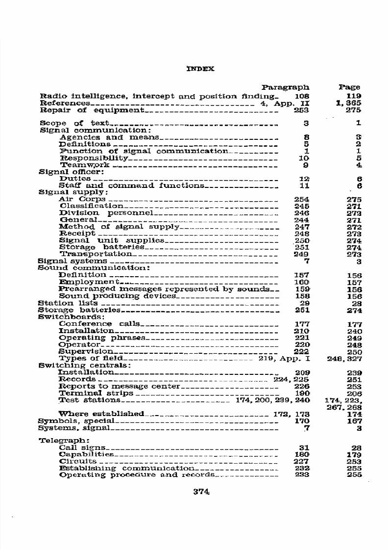
8/16/2019 (1942) FM 24-5 Signal Communication
http://slidepdf.com/reader/full/1942-fm-24-5-signal-communication 378/383
INDEX
Paragraph Page
Radio intelligence,
intercept
and
position
fnding_ 108 119
References
-_______________________________
4, App.
II
1,365
Repair of
equipment___________________________
253 275
Scope
of
text --
_______________________________
3
1
Signal
communication:
Agencies and
means__ --___________________-
8
3
Definitions______________________________
-
-5 2
Function
of
signal
communication_________-
1
1
Responsibility______--_____
-______________
10
5
Teamwork
-
--
_______________________________
9
4
Signal
officer:
Duties
-
-____________________________________
2
6
Staff
and
command
functions_____________
-11
6
Signal
supply:
Air Corps
-
-__________________________________
54
275
Classifcation
___________________________
245
271
Division
personnel_________________________
-246
272
General
--
_---_-- _______-_-________________
244
271
Method
of signal
supply -
----------_______
247
272
Receipt
-
-_________________----------------
48
273
Signal
unit
supplies
--
______________________
250
274
Storage batteries__
- -_______________________
51
274
Transportation
-
-__________________________
49
273
Signal systems
-----------------_-----________
__ 7
3
Sound communication:
Definition
------
____________________________
157
156
Employment-
-------______________________
160
157
Prearranged
messages
represented
by
sounds__
159
156
Sound
producing
devices --____________________
158
156
Station
lists ---------------
---.----------------
29
28
Storage
batteries ------------
___________________
251
274
Switchboards:
Conference
calls-_-__
_______________________
177
177
Installation
_
--
___________________________ 210
240
Operating
phrases___________________________
-221
249
Operator________________________________
-220
248
Supervision
___ _--__________________________
222
250
Types
of
field__________________________
219, App. I
248, 327
Switching centrals:
Installation --
_____________________________
209
239
Records
_--_-__________________.__________
224,
225
251
Reports
to
message
center____________________
-226
253
Terminal
strips_____________________________
-190
206
Test
stations______________________
174,
200,239,240
174, 223,
267,268
Where established_________________________
172, 173
174
Symbols,
special_________________________________
-170
167
Systems,
signal
____________________________
7
3
Telegraph:
Call signs
--------------------
______________
31
28
Capabilities
----____________________________
180
179
Circuits___________________
____________
227
253
Establishing
communication_________________
232
255
Operating procedure
and
records_____________
233
255
374

8/16/2019 (1942) FM 24-5 Signal Communication
http://slidepdf.com/reader/full/1942-fm-24-5-signal-communication 379/383
INDEX
Telegraph--Continued.
Paragraph
Page
Reports
and records_________________________ 182
181
Teletypewriters:
Capabilities____________________________
180
179
Central ---
---
___________-
-----
_ 181
179
Types of feld--------
___-- ____________
231, App. I 254, 327
Way
stations __-____________________________
230
254
Telephone:
Capabilities __________________-_____.________
171
173
Care of equipment__________________________
211
241
Conversations____-- ____-____--
._____________
176 176
Directory__
_______________._________
30, 175,
265in
28, 175,
319
Installation
of
__--__------
__________________
212 241
Testing
feld
telephones__--_________________
214 242
Traffic
diagram ________---
___-------______
223,264
251,
286
Types __-----
-_______--
-
-_-.__- ______ 213, App.
1
242,327
Text:
Object
--------
.
.-------_ -------------
-
2
1
Scope__---___________
__-------------______
3
1
Time,
Army and
Navy methods
of
specifying
_____ 28
27
Units,
signal
and communication_________________
6
3
Visual
call
signs_______
_____---_____--_______--
31
28
Visual
communication:
Airplanes---__---------___----------------_
-
156
154
Possibilities
and
employment____----
__------
122
127
Scope---------------------------------------
121
127
Wire:
Protection
___________-----
----------------
195
218
Recovery
________----
__-----------------
--
196
219
Splices:
Field
wire__-----------------------------
185
183
Special
___________.------------------ 186 189
Taping
__-------------------------------
187 194
Tags,
circuit-marking
-----------------------
189
204
Ties__---------------------------
-----------
188 197
Wire circuits:
Classification
-----------------.-------------
164
160
Designating
_____---------------------------
168
165
Routing
of
wire
lines__
--------------------
197
220
Wire
communication:
Construction center
_------------------------
208
236
Construction
orders
-----.------------------
198
220
Definitions_____
--------------------------
162 158
Movement
of
command
posts______--
___------
165
161
Ordern
and
instructions______-------------
166
165
Purpose
and
scope--__-----------------------
161
158
Transportation
of
equipment
_243
270
Wire-laying
equipment-----------------
194,
208,
App. I
218,236,
327
Wire
system:
Composition
--------------------------------
163
160
Reports
and
records_________---------------
182
181
375

8/16/2019 (1942) FM 24-5 Signal Communication
http://slidepdf.com/reader/full/1942-fm-24-5-signal-communication 380/383
FM
24-5
Cl1
BASIC
FIELD
MANUAL
SIGNAL
COMMUNICATION
CHANGES
1 WAR
DEPARTMENT,
No.1 f WASHINGTON 25,
D. C., 31
July
1943.
FM 24-5, 19 October 1942,
is
changed
as
follows:
·
24.
OPERATION.
* * * * * * *
b.
Location.-(1)
Signs to
mark
* * *
more
precise in-
structions. Message
center
marking
signs
shall
not
show
the
designation
or
size
of
the
unit,
but
may
have a tactical
marking as authorized in
paragraph
11, AR
850-5.
* * * * * * *
[A.
G.
300.7
(22
May
43).]
(C
1,
31
Jul
43.)
*
221.
OPERATING PHRASES.
* * * * * *
i.
"Have
you
finished?"
Used
by
an
* * * reply is
heard.
[A.
G.
300.7
(22
May
43).]
(C
1,
31 Jul
43.)
BY OBDER
OF
THE
SECBETABY
OF
WAR:
G. C.
MARSHALL,
Chief of Staff.
OFFICIAL:
J. A. ULIO,
Major General,
The
Adjutant
General.
376
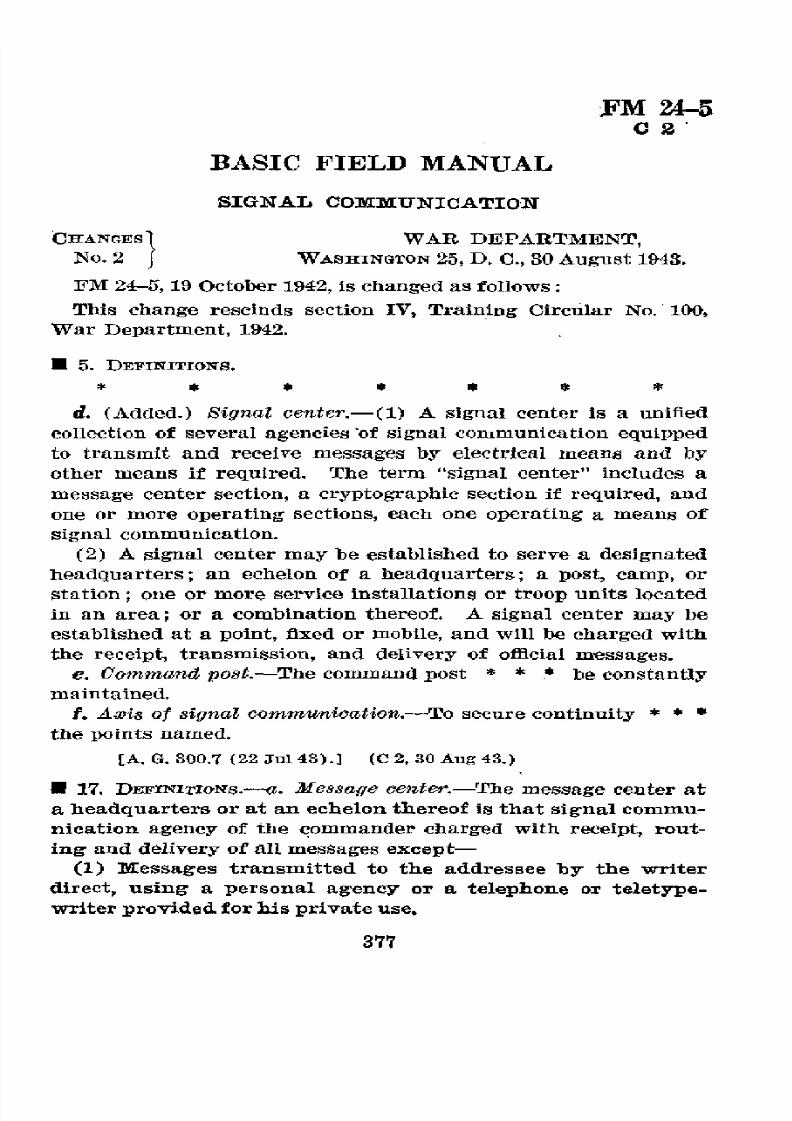
8/16/2019 (1942) FM 24-5 Signal Communication
http://slidepdf.com/reader/full/1942-fm-24-5-signal-communication 381/383
FM
24-5
C2
BASIC FIELD MANUAL
SIGNAL
COMIMUNICATION
CHANGEs
~
WAR
DEPARTMENT,
No. 2
WASHINGTON 25, D. C., 30 August 1943.
FM
24-5, 19 October 1942, is changed as follows:
This
change
rescinds
section
IV, Training
Circular
No. 100,
War Department,
1942.
*5.
DEFINITIONS.
d.
(Added.) Signal center.-(1)
A
signal
center
is
a
unified
collection of several agencies'of
signal
communication equipped
to transmit
and receive messages
by
electrical
means
and
by
other means if required. The term "signal center" includes a
message
center
section,
a
cryptographic
section
if
required, and
one or more operating sections,
each one operating
a means of
signal
communication.
(2)
A signal
center
may
be established
to
serve a designated
headquarters; an
echelon of a
headquarters;
a
post,
camp,
or
station; one or
more
service installations or troop units
located
in an area; or a combination thereof. A
signal center
may be
established
at a
point,
fixed
or
mobile,
and
will
be
charged with
the
receipt,
transmission,
and
delivery
of
official
messages.
e. Command
post.-The
command
post * *
* be
constantly
maintained.
f. Axis
of
signal
communication.-To
secure
continuity
* * *
the
points
named.
[A.
G.
300.7 (22
Jul 43).] (C 2,30
Aug
43.)
U
17.
DFIrrITIoNs.--a.
Message
center.-The
message
center
at
a headquarters or at an echelon thereof is that signal commu-
nication agency
of
the
commander charged
with
receipt, rout-
ing and
delivery
of all
messages
except-
(1) Messages transmitted
to
the addressee
by
the writer
direct, using
a
personal
agency or
a telephone
or
teletype-
writer
provided
for his private
use.
377
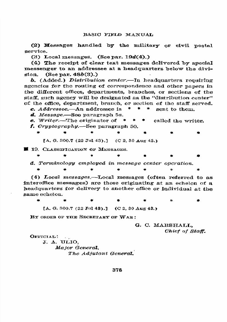
8/16/2019 (1942) FM 24-5 Signal Communication
http://slidepdf.com/reader/full/1942-fm-24-5-signal-communication 382/383
BASlO
FIELD
MANUAL
(2) Messages
handled
by
the military
or
civil postal
service.
(3) Localmessages.
(Seepar. 19d(4).)
(4)
The
receipt
of
clear
text
messages delivered
by
special
messenger to an addressee
at a headquarters
below the divi-
sion. (See par. 48b(3).)
b. (Added.)
Distribution
center.-In headquarters
requiring
agencies
for the routing of correspondence
and
other
papers
in
the different
offices, departments,
branches, or sections
of the
staff,
such
agency
will
be designated
as the "distribution
center"
of
the
oflice,
department,
branch,
or
section of
the
staff
served.
e. Addressee.-An
addressee
is
* * * sent to them.
d.
Message.-See
paragraph 5a.
e.
Writer.-The
originator of
*
*
* called the
writer.
f.
Cryptography.-See
paragraph
50.
*
* *
* * *
*
[A. G. 300.7 (22 Jul 43).]
(C 2,
30
Aug 43.)
O 19. CLASSIFICATION
OF MESSAGES.
* *
* *
* *
$
d. Terminology
employed in message
center
operation.
*
* *
* *
* *
(4)
Local
messages.-Local
messages (often
referred
to as
interoffice
messages)
are those
originating at an
echelon
of a
headquarters
for
delivery to
another
office
or individual
at
the
same
echelon.
* * *
* *
* $
[A. G. 300.7 (22 Ju143).]
(C
2,
30 Aug 43.)
BY ORDEn OF THE
SECBETARY OF WAR:
G. C. MARSHALL,
Chief of
Staff.
OFFICIAL:
J. A.
ULIO,
Major
General,
The Adjutant
General.
378

8/16/2019 (1942) FM 24-5 Signal Communication
http://slidepdf.com/reader/full/1942-fm-24-5-signal-communication 383/383
FM
24-15
C3
BASIC
FIELD MANUAL
SIGNAL
COMMUNICATION
CHANGES
}
WAR
DEPARTMENT,
No. 3
WASHINGTON
25,
D. C., 20 September
1943.
FM 24-5, 19
October 1942,
is
changed as follows:
* 188. WIRE
TIEs.
f.
(Added.) Basket
hitch
method of
tying
fleld wire.-(1)
Use.-The
most suitable
aerial
tie
for
Wire-110-B
under condi-
tions
of
extreme
heat,
long
spans, heavy wind, or sleet loading
is the
basket
hitch tie.
It
is also the
best
method
of tying
larger field
wire (such
as
Wire
W-143)
and
field
cable to
aerlal
fixtures,
and
to ground supports.
(2)
Procedure.-To
make
the tie,
use a single
conductor
of
scrap
field
wire
(W-110-B),
about
6
feet
long,
to
make
a
clove
hitch
around
the field
wire
or
cable
to
be
supported,
at such
a
point
that
the
several
hitches
of
the
completed
tie get a secure
grip
on the supported
conductors (fig.
61.1(1)). Lace
the ends
of
the
tie
wire
around
the field
wire or cable
in opposite
direc-
tlons until
enough
"baskets"
have
been formed
to provide
a
firm
grip
on
the
supported
conductors.
Usually
three complete
"baskets"
will provide
adequate support.
(See
fig. 61.1(2).)
Take
two turns
around
the supporting
structure
with
the
ends
of the tie wire
(fig. 61.1(3)
and (4)), and
terminate
the tie with
a
square
knot.
Cut
off
the
loose
ends,
leaving
the
ends
about
2 inches long.
--
or
CLOCVE
/ITC/