(19) united states (12) patent application publication … · a multi-hole orifice plate for flow...
TRANSCRIPT

(19) United States US 20160070271 A1
(12) Patent Application Publication (10) Pub. No.: US 2016/0070271 A1 HIRATA et al. (43) Pub. Date: Mar. 10, 2016
(54) MULTI-HOLE ORIFICE PLATE FOR FLOW (86). PCT No.: PCT/UP2O14/OO2O41 CONTROL, AND FLOW CONTROLLER S371 (c)(1) USING THE SAME (2) Date: Oct. 20, 2015
(71) Applicant: FUJIKIN INCORPORATED, Osaka (30) Foreign Application Priority Data (JP)
Apr. 25, 2013 (JP) ................................. 2013-09 1867 (72) Inventors: Kaoru HIRATA, Osaka-shi (JP):
Atsushi HIDAKA, Osaka-shi (JP): Masaaki NAGASE, Osaka-shi (JP); Ryousuke DOHI, Osaka-shi (JP): Nobukazu IKEDA, Osaka-shi (JP); Kouji NISHINO, Osaka-shi (JP): Katsuyuki SUGITA, Osaka-shi (JP); Takashi HIROSE, Osaka-shi (JP)
(73) Assignee: FUJIKIN INCORPORATED, Osaka (JP)
(21) Appl. No.: 14/785,789
(22) PCT Filed: Apr. 9, 2014
Publication Classification
(51) Int. Cl. GOSD 7/06 (2006.01) FI6L 55/027 (2006.01)
(52) U.S. Cl. CPC ........ G05D 7/0635 (2013.01); F16L 55/02718
(2013.01) (57) ABSTRACT
A multi-hole orifice plate for flow control includes an orifice plate for controlling the flow rate of a fluid, wherein the opening area of one orifice necessary for the passage of a predetermined flow rate of fluid is divided to provide a plu rality of orifices having a total opening area equal to said opening area.

Patent Application Publication Mar. 10, 2016 Sheet 1 of 9 US 2016/0070271 A1
Fig. 1

Patent Application Publication Mar. 10, 2016 Sheet 2 of 9 US 2016/0070271 A1
Fig. 2
5 F.S.130s.ccm CD67 um 100% n A 50% in 4. 6 input 50% input
3 • 20% input 10% hput
2 S 1 0 . . . . was u- 1
& 2 H. it 3 4 H -5 . . . . . . . . . . . . . . . . . . . . . . . .
O 0.2 0.4 0.6 0.8 1 P2/P1 Ratio
Fig. 3 5 F.S 850s.ccm d.179 um 1oog in A 4. 6 input 50% hput
3 • 20% input 10% input
S 1 6 . . . .
- 1 & 2 H. EE -5
O 0.2 0.4 0.6 0.8 1 P2/P1 Ratio
Patent Application Publication Mar. 10, 2016 Sheet 3 of 9 US 2016/0070271 A1
Fig. 4
FS.1600s.ccm (D250 um . 100% hput a 50% hput
- F
... . . . . . . . . . . . . . . . . . . . O 0.2 0.4 0.6 0.8 1
P2/P1 Ratio
Fig. 5 F.S.130ScCm (D67um
1.
o 1.
0.
1. O 20 40. 60 80
Setting 96) 1 O
Patent Application Publication Mar. 10, 2016 Sheet 4 of 9 US 2016/0070271 A1
Fig. 6
Fig. 7
F.S 850s.ccm (D179 um
-0. 5
1.w O 20 40 60 80 100
Setting 6)
F.S.1600s.ccm CD250 pum
-0.O.1. 1.
2
O 2 O 4 O 6 O 8 O 1 O Setting 6)


Patent Application Publication Mar. 10, 2016 Sheet 7 of 9 US 2016/0070271 A1
Fig. 10
Fig.11 F.S.6660s.ccm p79 pum X 37 orifices
O 100% hput A 50% hput • 20% input 10% hput
O O.2 O.4 O.6 0.8 1.
P2/P 1 Ratio

Patent Application Publication Mar. 10, 2016 Sheet 8 of 9 US 2016/0070271 A1
Fig. 12
i,
O. 5
are i. S
40 8 8 O

Patent Application Publication Mar. 10, 2016 Sheet 9 of 9 US 2016/0070271 A1
: (c/8 in)
6,033
WWWW-----> Upstream Side Pressure P1 kgf/cm2 abs)

US 2016/0070271 A1
MULT-HOLE ORIFICE PLATE FOR FLOW CONTROL, AND FLOW CONTROLLER
USING THE SAME
TECHNICAL FIELD
0001. The present invention relates to the improvement of an orifice plate for flow control and a pressure-controlled flow controller using the same. The invention particularly relates to a multi-hole orifice plate for flow control configured such that, in a pressure-controlled flow controller for use in a gas Supply apparatus for a semiconductor manufacturing system, etc., the range of the pressure ratio P/P between the pressure P. upstream of the orifice and the pressure P, downstream of the orifice, at which the critical expansion conditions of an orifice-passing fluid are established, can be kept wide and stable, thereby making it possible to achieve high-precision flow control over a wide flow range; and also relates to a pressure-controlled flow controller using the same.
BACKGROUND ART
0002. When the pressure ratio P/P between the pressure P. upstream of the orifice and the pressure P, downstream of the orifice is equal to or lower than the pressure ratio at which the critical expansion conditions of a gas are established, the orifice-passing gas flows at the speed of sound, and a variation in the pressure P downstream of the orifice is not transmitted to the upstream side. As a result, when the orifice has a fixed diameter, regardless of the kind of gas, the flow rate of the gas passing through the orifice plate changes in direct proportion to the gas pressure P. upstream of the orifice. 0003. Meanwhile, utilizing such characteristics of an ori
fice, a large number of fluid flow controller using an orifice have been developed. 0004 FIG. 13 shows an example of the configuration of the pressure-controlled flow controller using an orifice previ ously disclosed by the present inventors. The flow controller 21 includes a control valve 22, a pressure detector 23, a temperature detector 24, an orifice 25, an arithmetic and control unit 26, amplifiers 27a and 27b, A/D converters 28a and 28b, and the like (JP-A-8-338546). 0005. The fluid pressure P, upstream of the orifice 25 is detected by the pressure detector 23 and input to the arith metic and control unit 26. In the arithmetic and control unit 26, the flow rate Qc is calculated using the arithmetic expres sion Qc-KP, while Qc is compared with the flow command value QS, and the control signal Qy corresponding to the difference between the two, Qc-Qs, is input to an actuator 30 of the control valve 22. 0006. In addition, the control valve 22 is opened/closed by the control signal Qy in the direction that the difference Qc-Qs approaches zero, whereby the flow rate downstream of the orifice 25 is constantly maintained at the set flow rate (flow command value) QS. 0007 Further, the orifice 25 is formed by making a small hole having an inner diameter of 0.01 to 0.20 mm in a metal plate having a thickness of 0.02 to 0.20 mm by pressing, electric discharge machining, or etching. The diameter of the orifice is appropriately selected according to the required gas flow rate to be controlled. 0008 Furthermore, although electric discharge machining or etching is generally used to form an orifice 25, in some cases, the orifice is formed by So-called cutting using a drill in order to reduce the processing cost (JP-A-11-117915).
Mar. 10, 2016
0009 FIG. 14 shows the flow control characteristics of the pressure-controlled flow controller of FIG. 13 in the case where the gas is nitrogen gas, and shows the case where the pressure downstream of the orifice 25 is atmospheric pres SUC.
0010. As clearly shown in FIG. 14, at a range where the pressure Pupstream side exceeds about twice the pressure P. on the downstream side, the relation between the flow rate Qc and P is kept linear, and Qc is in direct proportion to the pressure P. upstream of the orifice. Thus, by automatically controlling the pressure P. upstream of the orifice, the feed back control of the flow rate through the orifice is possible. Furthermore, in FIG. 14, A shows the flow control character istics in the case where the diameter of the orifice is p0.37 mm, while B is in the case of 0.20(p. 0011. As clearly shown in FIG. 14, when the lines A and B are both within a range of P.<0.5P (i.e., P/P<0.5), the linearity is well maintained, and the flow rate can be precisely controlled by regulating P. 0012 However, it is known that the actual lower limit of P at which the critical expansion conditions of a gas are estab lished (P/P<0.5 or P/P2 >2) (i.e., the lower limit of P at which the linearity is maintained) slightly changes with the inner diameter of the orifice, and the greater the diameterofan orifice is, the smaller the range of P/P at which critical expansion conditions are established tends to be. That is, when P is constant, the lower limit of the control range of P increases. 0013 Specifically, with an increase in the diameter of an orifice, the critical pressure ratioP/P<0.5 decreases to about P/P<0.45, and when P is constant, the lower limit of the control range of P increases, resulting in a smaller control range of P. 0014. In other words, when the diameter of an orifice increases with an increase in the controlled flow rate of a flow controller, the control range of the critical pressure ratio P/P becomes Smaller. This results in various inconveniences in the case where, for example, the gas is Supplied to a vacuum chamber of a semiconductor manufacturing system. 0015. As mentioned above, the conventional pressure type flow controller using an orifice plate provided with one orifice has the drawback that the pressure ratio P/P at which critical expansion conditions are established varies with an increase in the diameter of the orifice, resulting in the varia tion of the flow (pressure) control range. Therefore, in the technical field of pressure-controlled flow controllers applied to semiconductor manufacturing systems, there has been a strong demand for the advent an orifice plate for flow control, in which even when the diameter of an orifice changes, no variation occurs in the actual pressure ratio P/P at which critical expansion conditions are established; and also a pres Sure-controlled flow controller using the same.
CITATION LIST
Patent Literature
Patent Document 1: JP-A-8-338546 Patent Document 2: JP-A-11-117915
0016 0017
SUMMARY OF INVENTION
Technical Problem
0018. A main object of the present invention is to solve the problems of conventional orifice plates for flow control and

US 2016/0070271 A1
pressure-controlled flow controllers using the same men tioned above, that is, the problems that the actual pressure ratio P/P at which critical expansion conditions are estab lished varies (decreases) with an increase in the inner diam eter of an orifice, whereby the control range of the pressure ratio P/P becomes smaller, and also the flow control accu racy of the pressure-controlled flow controller decreases, etc., and provide an orifice plate for flow control, which is config ured such that even when the inner diameter of an orifice is increased with an increase in the fluid flow rate, the pressure ratio P/P in the actual flow control can always be kept constant, and also the production cost for the orifice plate can be reduced; and also provide a pressure-controlled flow con troller using the same.
Solution to the Problems
0019 First, with respect to an orifice plate having one orifice (hereinafter referred to as single-hole orifice plate), the present inventors examined the degree of actual variation of the ratio P/P between the pressure P. upstream of the orifice and the pressure P downstream of the orifice (hereinafter referred to as pressure ratio P/P), at which the critical expansion conditions of a fluid are established, in accordance with a change in the diameter (p of the orifice. 0020 FIG. 1 is a system diagram of a testing device (flow measuring device) used for testing the pressure ratio P/P, flow characteristics and the like of a conventional single-hole orifice plate for flow control and the multi-hole orifice plate for flow control according to the present invention; 1 is a gas inlet, 2 is a pressure regulator, 3 is a pressure meter, 4 is a molblock flow meter, 5 is a pressure-controlled flow control ler, 6 is a control valve, 7 is an orifice plate, 8 is a pressure detector upstream of the orifice, 9 is a pressure detector down stream of the orifice, 10 is a regulation valve for the pressure P downstream of the orifice, 11 is an evacuation pump, P is the pressure upstream of the orifice, and P is the pressure downstream of the orifice. Furthermore, the maximum flow range F.S. is based on N gas. 0021. The orifice plates used for the test were the follow ing three kinds: 50-um-thick steel plates having orifices of (p=67 um, (p=179 um, and cp=250 um, respectively. The orifice of p=67 um is used in a pressure-controlled flow controller 5 with a maximum flow range (full scale) F.S. =130 sccm, the orifice of p=250 um is used in a pressure-controlled flow controller 5 with a maximum flow range F.S. of 850 sccm, and the orifice of p=250 Lum is used in a pressure-type flow con troller 5 with a maximum flow range F.S. =1600 sccm. 0022. In the test, first, the pressure Po of the pressure meter 3 is regulated to 300 kPa abs by the pressure regulator 2. Next, the set flow rate of the pressure-controlled flow controller 5 is set at 100% F.S. (a rated flow rate), and the evacuation pump 11 is operated. Subsequently, while regulating the regulation valve 10 upstream of the evacuation pump 11 to regulate the pressure P downstream of the orifice, the gas flow rates in the molblock flow meter 4 and the pressure-type flow controller 5 are each measured. Furthermore, N gas was used as the test gaS. 0023) Next, using the measured flow rate Qs of the mol block flow meter 4 as the reference value, the error (set point error (S.P.9%)) of the measured flow rate Qc of each pressure controlled flow controller 5 was calculated as (Qc-Qs)x100/ Qs (S.P. 96). Furthermore, the flow measurement was mea sured at 100%, 50%, 20%, and 10% of the set flow rate of the pressure-controlled flow controller 5.
Mar. 10, 2016
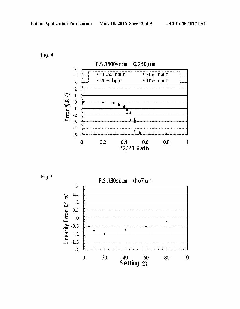
0024. With respect to the three kinds of pressure-con trolled flow controllers having different orifice diameters (F S. 130 sccm, F.S. 850 sccm, F.S. 1600 sccm), each of FIG.2, FIG. 3, and FIG. 4 shows the relation between the pressure ratio (P/P) and the set point error (S.P. 96) by using the set input (set flow rate) to each pressure-controlled flow control ler 5 as a parameter. From the comparison of FIG. 2 to FIG.4, it was confirmed that with an increase in the flow range (rated flow rate S.P.) and a resulting increase in the orifice diameter, the set pointerror (S.P.96) approaches Zero, that is, the range of P/P at which critical expansion conditions are established becomes Smaller.
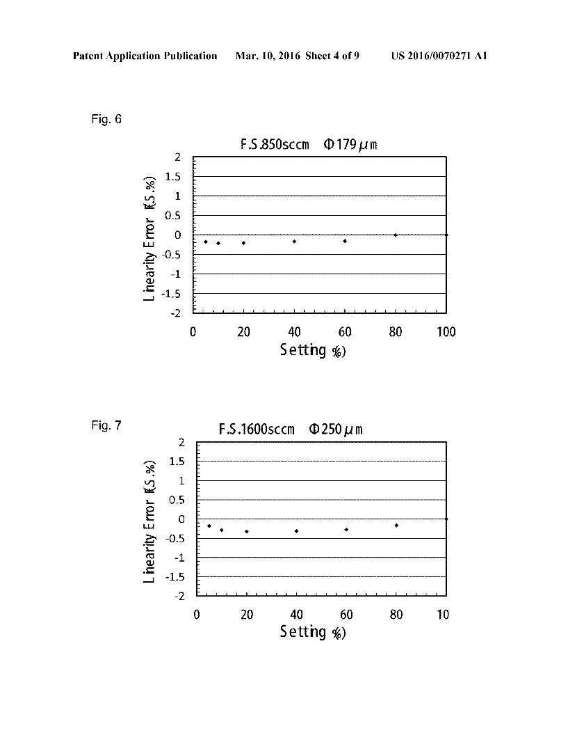
0025. In addition, from the flow control results obtained using the testing device of FIG. 1, FIG. 5, FIG. 6, and FIG.7 each show the relation between the set flow rate (%) of the pressure ratio P/P when the set pointerror (S.P.96) is within +1% and the flow linear error (F.S. 96) based on the controlled flow rate at the time of 100% setting, that is, the relation between the set flow rate (%) and the linearity error (F.S. 96). It was shown that within the range of the pressure ratio P/P at which critical expansion conditions are established, the flow linear error F.S. 9% of the single-hole orifice plate is within +1% F.S.
0026. The present invention has been created based on the results of the flow characteristic tests as shown in FIG. 2 to FIG. 7. Noting that the smaller the diameter of the orifice of a single-hole orifice plate, the greater the range of the pressure ratio P/P at which critical expansion conditions are estab lished, the present inventors have conceived that in the case when the controlled flow rate increases, rather than increasing the diameter of the orifice of a single-hole orifice plate according to the flow rate range as conventional, when the number of orifices of a multi-hole orifice plate on which each orifice has a small diameter is changed, thereby correspond ing to the increase of the controlled flow rate, the flow rate increase can be managed while the range of the pressure ratio P/P at which the critical expansion conditions of the orifice passing fluid are established is being kept maximum and COnStant.
0027. A first aspect of the present invention is basically configured such that in an orifice plate for flow control, the opening area of one orifice necessary for the passage of a predetermined flow rate of fluid is divided to provide a plu rality of Smaller orifices having a total opening area equal to said opening area. 0028. According to a second aspect of the present inven tion, in the first aspect, the plurality of orifices are formed by pressing. 0029. According to a third aspect of the present invention, in the above first aspect, the orifice plate has a thickness of 20 to 200 um and serves as an orifice plate for a pressure-con trolled flow controller.
0030. According to a fourth aspect of the present inven tion, in the above first aspect, the orifice plate has a thickness of 20 to 200 um, the plurality of orifices each have a hole diameter of 0.010 to 0.200 mm, and the number of the plu rality of orifices is 2 to 100. 0031. According to a fifth aspect of the present invention, in the above first aspect, the plurality of orifices each has a longitudinal plane shape including a rectangular part and a trapezoidal part.

US 2016/0070271 A1
0032. According to a sixth aspect of the present invention, in the above fifth aspect, a portion on the backside of the orifice plate having the plurality of orifices bored therein is finished by polishing. 0033 According to a seventh aspect of the present inven
tion, in the first aspect, when the ratio P/P between the pressure (P) upstream of the orifice and the pressure (P.) downstream of the orifice is equal to or lower than the pres Sure ratio at which the critical expansion conditions of a gas are established, the gas flow rate Q changes in direct propor tion to the gas pressure (P) upstream of the orifice. 0034. An eighth aspect of the present invention is basically configured Such that in a pressure-controlled flow controller, the multi-hole orifice according to any one of the preceding aspects is used as an orifice plate for flow control.
Advantageous Effects of Invention
0035. In the present invention, in an orifice plate for flow control configured Such that a fluid flows under critical expan sion conditions, and the flow rate Q of the orifice-passing fluid is in direct proportion to the pressure P. upstream of the orifice, the opening area of one orifice necessary for the passage of a desired flow rate of fluid is divided to provide a plurality of orifices having a total opening area equal to said opening area. 0036. As a result, even when the orifice opening area increases with an increase in the controlled flow rate, the pressure ratio P/P between the pressure P. upstream of the orifice and the pressure P on the downstream side at which critical expansion conditions are established does not actually vary and is maintained at a constant value, whereby the reduc tion of the control range of P/P (flow control range) can be effectively prevented. In addition, in a pressure-controlled flow controller using the orifice plate, it is made possible to increase the flow control range and improve the control pre cision. 0037. In addition, since the plurality of orifices can be easily formed by pressing, the orifice plate can be produced at a lower cost, compared with the conventional production by laser beam machining, etc.
BRIEF DESCRIPTION OF DRAWINGS
0038 FIG. 1 is a system diagram of a testing device used for testing the orifice flow characteristics. 0039 FIG. 2 is a line chart showing the relation between pressure ratio P/P and set pointerror (S.P.96) of a pressure controlled flow controller with F.S. 130 sccm.
0040 FIG. 3 is a line chart similar to FIG. 2 with F.S. 850 SCC.
0041 FIG. 4 is a line chart similar to FIG. 2 with F.S. 1600 SCC.
0042 FIG. 5 is a line chart showing the relation between the set flow rate (%) at a pressure ratio P/P at which the set point error S.P.96 is within +1% and the error relative to full scale (linearity error) (F.S. 96), with respect to a pressure controlled flow controller with F.S. 130 sccm.
0043 FIG. 6 is a line chart similar to FIG. 5 with F.S. 850 SCC.
0044 FIG. 7 is a line chart similar to FIG.5 with F.S. 1600 SCC.
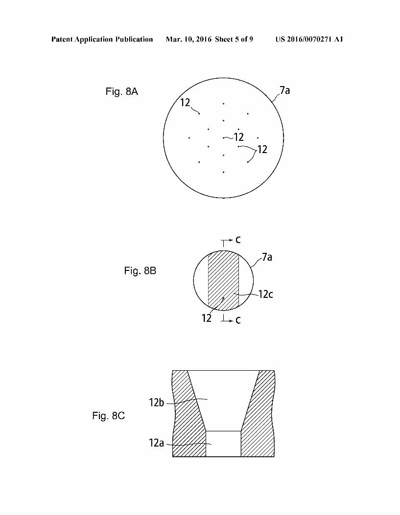
0045 FIG. 8A shows a plane view of an example of the multi-hole orifice plate according to the present invention,
Mar. 10, 2016
FIG.8B shows a back view of FIG. 8A, and FIG. 8C shows a c-c sectional view of FIG. 8B. 0046 FIG. 9A is a plan view showing another example of the multi-hole orifice plate according to the present invention, FIG.9B shows a back view of FIG. 9A and FIG.9C shows a Sectional view of FIG.9B. 0047 FIG. 10 is a plan view showing another example of the multi-hole orifice plate according to the present invention. 0048 FIG. 11 is a line chart showing relation between the pressure ratio P/P and the set point error (S.P.9%) similar to FIG. 2 to FIG. 4 in the case of using the multi-hole orifice plate of FIG. 10. 0049 FIG. 12 is a line chart showing relation between the set flow rate (%) and the linearity error (F.S. 96) similar to FIG. 5 to FIG. 7 in the case of using the multi-hole orifice plate of FIG. 10. 0050 FIG. 13 is a block diagram of a known pressure controlled flow controller. 0051 FIG. 14 is a line chart showing the flow control characteristics of the pressure-controlled flow controller of FIG. 13.
DESCRIPTION OF EMBODIMENTS
0.052 Hereinafter, the present invention will be described based on embodiments and drawings. 0053 FIG. 8A, FIG.8B, and FIG.8C show an example of the orifice plate for flow control according to the present invention: FIG. 8A is a plan view, FIG.8B is a back view, and FIG. 8C is a c-c sectional view. 0054. In FIG. 8A, a total of fifteen orifices 12 with a diameter of 0.085 mm are provided in an orifice plate 7a with an outer diameter of 3.5 mm and a thickness of 0.05 mm 0055. In addition, the longitudinal plane shape of the ori fice 12 is formed by pressing to have a rectangular part 12a and a trapezoidal part 12b as shown in FIG. 8C, and the depth of the orifice 12 is 0.05 mm, which is the same as the thickness of the orifice plate 7a. 0056 Furthermore, the portion on the back side of the orifice plate 7a, where the orifices 12 are provided, is polished in a narrow shape to form a polished surface 12c, and the front and back of the orifice plate 7a are distinguished by the polished surface 12c. 0057 FIG. 9A, FIG. 9B, and FIG. 9C shows another example of the multi-hole orifice plate 7a for flow control according to the present invention, which is the same as the multi-hole orifice plate for flow control of FIG. 8A, FIG.8B, and FIG.8C, except that the number of orifices 12 is 5, and the orifices 12 each has a diameter of 0.135 mm 0.058 FIG. 10 is an enlarged plan view showing another example of the multi-hole orifice plate 7a for flow control according to the present invention, in which thirty-seven ori fices 12 each having a diameter (p of 79 um (0.079 mm) are provided. 0059. The outer diameter, the thickness, and the like of the orifice plate 7a are the same as those of the orifice plates 7a of FIG. 8A and FIG.9A. 0060. The diameter (p of 79 um of the orifice 12 is equal to the diameter of the orifice of a single-hole orifice plate 7 of Pressure-Controlled Flow Controller F180 manufactured by Fujikin Incorporated, which is a control orifice plate with a rated flow rate of 180 sccm (F.S.). 0061 Accordingly, the F.S. flow rate of the multi-hole orifice plate 7a for flow control of FIG. 10 is equivalent to 180 sccmx37 =6.660 sccm.

US 2016/0070271 A1
0062 FIG. 11 shows a curve similar to FIG. 2, showing the relation with the pressure ratio P/P, wherein the single-hole orifice plate 7 of the tester of FIG. 1 is replaced by the multi-hole orifice plate 7a of FIG. 10. 0063 As is clear from the comparison between FIG. 11 and FIG. 2, in the case of the multi-hole orifice plate 7a of the present invention, the pressure ratio P/P value at which the set point error (S.P.9%) is within a range of +1% does not fall below 0.45 even at the time of 10% input (10% of the set flow rate). At the time of 100% input (100% of the set flow rate), the P/P, value of about 0.52 can be obtained. 0064. In contrast, in FIG. 3 in which the maximum flow rate is 850 sccm, the pressure ratio P/P at the time of 100% input is about 0.42. Even in FIG. 4 in which the maximum flow rate is 1600 sccm, the pressure ratio P/P at the time of 100% input is about 0.40. This shows that in the case where the multi-hole orifice plate 7a of the invention of the present application is used, the range of P/P whereat critical expan sion conditions are established can be expanded. In addition, the reason why the theoretical pressure ratio P/P whereat critical expansion conditions are established is slightly dif ferent from the pressure ratio P/P at which critical expan sion conditions are established in actual measurement as above has not been theoretically analyzed yet and is currently under examination. However, it is assumed that it is affected by differences in the flowing condition of the fluid on the orifice outlet side. 0065 FIG. 12 is a line chart similar to FIG. 5 in the case of using the multi-hole orifice plate 7a of the present invention. The line chart shows the relation between the set flow rate (%) at a pressure ratio P/P whereat the set point error (S.P.9%) is within +1% and the error relative to the control flow at the time of 100% setting (flow linear error) (F.S. 96). 0066. As clearly shown in FIG. 12, it has been confirmed that the multi-hole orifice plate 7a of the present invention also results in a flow linear error (F.S. 96) within +1% F.S. 0067. In addition, the pressure-controlled flow controller according to the present invention is given by replacing the orifice plate of the Pressure-Controlled Flow Controller F180 manufactured by Fujikin Incorporated, the pressure-con trolled flow controller shown in FIG. 13, or the like with the orifice plate of the present invention. Thus, the detailed description will be omitted. 0068. As described above, in the multi-hole orifice plate for flow control and the pressure-controlled flow controller using the same according to the present invention, by adjust ing the number of orifices 12 based on the controlled flow rate even when the controlled flow rate increases, the range of the pressure ratio P/P at which critical expansion conditions are established can be maintained wide and constant, thereby making it possible to perform high-precision flow control stably over a wide range.
INDUSTRIAL APPLICABILITY
0069. The multi-hole orifice plate according to the present invention can be applied not only to a pressure-controlled flow controller but also to any orifices in ordinary orifice devices inserted into a pipeline to control the fluid flow, fluid diverters, etc.
REFERENCE SIGNS LIST
1: Gas inlet 2: Pressure regulator
0070 0071
Mar. 10, 2016
0072 3: Pressure meter 0073 4: Molblock flow meter (0074 5: Pressure-type flow controller 0075 6: Control valve (0076 7: Orifice plate (single-hole) (0077 7a: Multi-hole orifice plate 0078 8: Pressure detector on the orifice upstream side 0079 9: Pressure detector on the orifice downstream side 0080 10: Regulation valve for the pressure P, on the ori fice downstream side
I0081) 11: Evacuation pump I0082 P: Pressure on the orifice upstream side I0083 P: Pressure on the orifice downstream side I0084 P: Pressure on the gas supply source side 0085 12: Orifice 1. A multi-hole orifice plate for flow control, comprising an
orifice plate for controlling the flow rate of a fluid, wherein the opening area of one orifice necessary for the passage of a predetermined flow rate of fluid is divided to provide a plu rality of orifices having a total opening area equal to said opening area.
2. The multi-hole orifice plate for flow control according to claim 1, wherein the plurality of orifices are formed by press 1ng.
3. The multi-hole orifice plate for flow control according to claim 1, wherein the orifice plate has a thickness of 20 to 200 um and serves as an orifice plate for a pressure-controlled flow controller.
4. The multi-hole orifice plate for flow control according to claim 1, wherein the orifice plate has a thickness of 20 to 200 um, the plurality of orifices each have a bore of 0.010 to 0.200 mm, and the number of the plurality of orifices is 2 to 100.
5. The multi-hole orifice plate for flow control according to claim 1, wherein the plurality of orifices each have a longitu dinal plane shape including a rectangular part and a trapezoi dal part.
6. The multi-hole orifice plate for flow control according to claim 5, wherein a portion on the back side of the orifice plate having the plurality of orifices bored therein is finished by polishing.
7. The multi-hole orifice plate for flow control according to claim 1, wherein when the ratio P/P between the pressure (P) upstream of the orifice and the pressure (P) downstream of the orifice is equal to or lower than the pressure ratio at which the critical expansion conditions of a gas are estab lished, the gas flow rate changes in direct proportion to the gas pressure (P) upstream of the orifice.
8. A pressure-controlled flow controller using an orifice plate, wherein the orifice plate is the multi-hole orifice plate for flow control according to claim 1.
9. A pressure-controlled flow controller using an orifice plate, wherein the orifice plate is the multi-hole orifice plate for flow control according to claim 2.
10. A pressure-controlled flow controller using an orifice plate, wherein the orifice plate is the multi-hole orifice plate for flow control according to claim 3.
11. A pressure-controlled flow controller using an orifice plate, wherein the orifice plate is the multi-hole orifice plate for flow control according to claim 4.
12. A pressure-controlled flow controller using an orifice plate, wherein the orifice plate is the multi-hole orifice plate for flow control according to claim 5.

US 2016/0070271 A1
13. A pressure-controlled flow controller using an orifice plate, wherein the orifice plate is the multi-hole orifice plate for flow control according to claim 6.
14. A pressure-controlled flow controller using an orifice plate, wherein the orifice plate is the multi-hole orifice plate for flow control according to claim 7.
k k k k k
Mar. 10, 2016