(19) tzz¥ z¥ t
TRANSCRIPT

Printed by Jouve, 75001 PARIS (FR)
(19)E
P3
103
572
A1
(Cont. next page)
TEPZZ¥_Z¥57 A_T(11) EP 3 103 572 A1
(12) EUROPEAN PATENT APPLICATIONpublished in accordance with Art. 153(4) EPC
(43) Date of publication: 14.12.2016 Bulletin 2016/50
(21) Application number: 15843784.8
(22) Date of filing: 18.09.2015
(51) Int Cl.:B23B 27/14 (2006.01) C23C 16/34 (2006.01)
C23C 16/36 (2006.01)
(86) International application number: PCT/JP2015/076645
(87) International publication number: WO 2016/047581 (31.03.2016 Gazette 2016/13)
(84) Designated Contracting States: AL AT BE BG CH CY CZ DE DK EE ES FI FR GB GR HR HU IE IS IT LI LT LU LV MC MK MT NL NO PL PT RO RS SE SI SK SM TRDesignated Extension States: BA MEDesignated Validation States: MA
(30) Priority: 25.09.2014 JP 2014195795
(71) Applicant: Mitsubishi Materials CorporationChiyoda-kuTokyo 100-8117 (JP)
(72) Inventors: • TATSUOKA Sho
Naka-shiIbaraki 311-0102 (JP)
• SATO KenichiNaka-shiIbaraki 311-0102 (JP)
• YAMAGUCHI KenjiNaka-shiIbaraki 311-0102 (JP)
(74) Representative: Gille HrabalBrucknerstrasse 2040593 Düsseldorf (DE)
(54) SURFACE-COATED CUTTING TOOL IN WHICH HARD COATING LAYER EXHIBITS EXCELLENT CHIPPING RESISTANCE
(57) Provided is a coated tool in which a hard coating layer has excellent hardness and toughness and exhibitschipping resistance and defect resistance during long-term use. A surface-coated cutting tool is formed by coating thesurface of a tool body with a (Ti1-xAlx) (CyN1-y) layer (the average amount Xavg of Al and the average amount Yavg ofC satisfy 0.60 ≤ Xavg ≤ 0.95 and 0 ≤ Yavg ≤ 0.005). Crystal grains having an NaCl type face-centered cubic structurein the layer have {111} orientation, a columnar structure in which the average grain width W of the individual crystalgrains having an NaCl type face-centered cubic structure is 0.1 mm to 2.0 mm and the average aspect ratio A thereof is2 to 10 is included, and in the individual crystal grains having an NaCl type face-centered cubic structure, a periodiccompositional variation in Ti and Al in the composition formula: (Ti1-xAlx) (CyN1-y) is present and the difference Δx betweenthe average of maximum values of x which varies periodically and the average of minimum values thereof is 0.03 to 0.25.
EP 3 103 572 A1
2

EP 3 103 572 A1
3
5
10
15
20
25
30
35
40
45
50
55
Description
Technical Field
[0001] The present invention relates to a surface-coated cutting tool (hereinafter, referred to as coated tool), in whicha hard coating layer exhibits excellent chipping resistance during high-speed intermittent cutting work of alloy steel orthe like during which high-temperature heat is generated and an impact load is exerted on a cutting edge, and excellentcutting performance is exhibited during long-term use.
Background Art
[0002] Hitherto, in general, coated tools in which the surfaces of tool bodies made of tungsten carbide (hereinafter,referred to as WC)-based cemented carbide, titanium carbonitride (hereinafter, referred to as TiCN)-based cermet, ora cubic boron nitride (hereinafter, referred to as cBN)-based ultrahigh-pressure sintered body (hereinafter, collectivelyreferred to as a tool body) are covered with a Ti-Al-based complex nitride layer as a hard coating layer through a physicalvapor deposition method are known, and it is known that these coated tools exhibit excellent wear resistance.[0003] However, although the coated tool coated with the Ti-Al-based complex nitride layer in the related art hasrelatively excellent wear resistance, in a case of using the coated tool under high-speed intermittent cutting conditions,abnormal wear such as chipping easily occurs. Therefore, various suggestions for an improvement in the hard coatinglayer have been made.[0004] For example, PTL 1 discloses that a coating which is excellent in wear resistance, seizure resistance, andoxidation resistance, has a low coefficient of friction, and has good sliding characteristics is obtained by forming a complexhard coating made of at least two types of metal nitride among nitrides of Cr, Ti, Al, and V on the surface of a tool bodyand causing the strength ratio I(111) / 1(200) between the strengths I(111) and 1(200) of the X-ray diffraction peaks ofa (111) plane and a (200) plane obtained through X-ray diffraction of the hard coating to be a value of 3 to 6.[0005] For example, PTL 2 describes that by performing chemical vapor deposition in a mixed reaction gas of TiCl4,AlCl3, and NH3 in a temperature range of 650°C to 900°C, a (Ti1-xAlx) N layer in which the value of the amount x of Alis 0.65 to 0.95 can be deposited. However, this literature is aimed at further coating the (Ti1-xAlx) N layer with an Al2O3layer and thus improving a heat insulation effect. Therefore, the effects of the formation of the (Ti1-xAlx) N layer in whichthe value of the amount x of Al is increased to 0.65 to 0.95 on cutting performance is not clear.[0006] In addition, for example, PTL 3 suggests that the heat resistance and fatigue strength of a coated tool areimproved by coating a TiCN layer and an Al2O3 layer as inner layers with a (Ti1-xAlx)N layer (x is 0.65 to 0.90 in termsof atomic ratio) having a cubic structure or a cubic structure including a hexagonal structure as an outer layer, andapplying a compressive stress of 100 MPa to 1100 MPa to the outer layer.
Citation List
Patent Literature
[0007]
[PTL 1] JP-A-2000-144376[PTL 2] JP-T-2011-516722[PTL 3] JP-T-2011-513594
Summary of Invention
Technical Problem
[0008] There has been a strong demand for power saving and energy saving during cutting work in recent years. Inaccordance with this, there is a trend toward a further increase in speed and efficiency during cutting work. Therefore,abnormal damage resistance such as chipping resistance, defect resistance, and peeling resistance is further requiredfor a coated tool, and excellent wear resistance is required during long-term use.[0009] However, in a coated tool described in PTL 1, since the hard coating is deposited through the physical vapordeposition method, for example, it is difficult to increase the amount of Al in the hard coating. Therefore, in a case wherethe coated tool is provided for high-speed intermittent cutting work of alloy steel or the like, there is a problem in that itcannot be said that wear resistance and chipping resistance are sufficient.[0010] On the other hand, in the (Ti1-xAlx)N layer deposited through the chemical vapor deposition method described
EP 3 103 572 A1
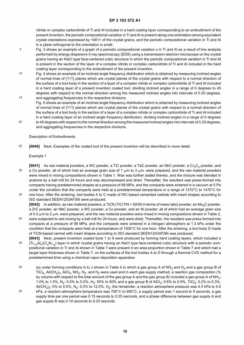
4
5
10
15
20
25
30
35
40
45
50
55
in PTL 2, the amount x of Al can be increased. In addition, since a cubic structure can be formed, a hard coating layerhaving a predetermined hardness and excellent wear resistance is obtained. However, there are problems in that theadhesive strength thereof to a tool body is insufficient and the toughness thereof may be deteriorated.[0011] Furthermore, in the coated tool described in PTL 3, although the coated tool has a predetermined hardnessand excellent wear resistance, the toughness thereof is deteriorated. Therefore, in a case where the coated tool isprovided for high-speed intermittent cutting work of alloy steel or the like, there are problems in that abnormal damagesuch as chipping, defects, and peeling easily occurs and it cannot be said that satisfactory cutting performance is exhibited.[0012] Here, a technical problem to be solved by the present invention, that is, an object of the present invention is toprovide a coated tool which has excellent toughness and exhibits excellent chipping resistance and wear resistanceduring long-term use even in a case of being provided for high-speed intermittent cutting work of alloy steel or the like.
Solution to Problem
[0013] Therefore, from the above-described viewpoints, the inventors intensively studied to improve the chippingresistance and wear resistance of a coated tool in which a hard coating layer containing at least a complex nitride orcomplex carbonitride of Ti and Al (hereinafter, sometimes referred to as "(Ti,Al)(C,N)" or "(Ti1-xAlx)(CyN1-y)") is depositedthrough chemical vapor deposition. As a result, the following knowledge was obtained.[0014] That is, in the related art, in a hard coating layer which includes at least one (Ti1-xAlx)(CyN1-y) layer and has apredetermined average layer thickness, in a case where the (Ti1-xAlx)(CyN1-y) layer is formed in a columnar shape in adirection perpendicular to a tool body, the hard coating layer has high wear resistance. On the other hand, as theanisotropy of the (Ti1-xAlx)(CyN1-y) layer increases, the toughness of the (Ti1-xAlx)(CyN1-y) layer decreases. As a result,the chipping resistance and defect resistance thereof decrease, and sufficient wear resistance is not exhibited duringlong-term use. In addition, it cannot be said that the service life of the tool is satisfactory.[0015] The inventors intensively studied a (Ti1-xAlx)(CyN1-y) layer included in a hard coating layer, and on the basisof a completely novel idea that a periodic compositional variation in Ti and Al in crystal grains having an NaCl type face-centered cubic structure in the (Ti1-xAlx)(CyN1-y) layer is formed, obtained novel knowledge that an increase in bothhardness and toughness is achieved by introducing strain into the crystal grains having an NaCl type face-centeredcubic structure, and as a result, the chipping resistance and wear resistance of the hard coating layer can be improved.[0016] Specifically, it was found that the hard coating layer includes at least a layer of a complex nitride or complexcarbonitride of Ti and Al, which is formed by a chemical vapor deposition method, in a case where the layer is expressedby the composition formula: (Ti1-xAlx)(CyN1-y), the average amount Xavg of Al in the total amount of Ti and Al and theaverage amount Yavg of C in the total amount of C and N (both Xavg and Yavg are atomic ratios) respectively satisfy0.60 ≤ Xavg ≤ 0.95 and 0 ≤ Yavg ≤ 0.005, the layer of a complex nitride or complex carbonitride includes at least a phaseof a complex nitride or complex carbonitride having an NaCl type face-centered cubic structure, regarding the layer, ina case where the layer is analyzed in a longitudinal sectional direction of the layer using an electron backscatter diffractionapparatus, when an inclined angle frequency distribution is obtained by measuring inclined angles of normal lines of{111} planes which are crystal planes of the crystal grains with respect to a normal direction of the surface of the toolbody, dividing inclined angles in a range of 0 degrees to 45 degrees with respect to the normal direction among themeasured inclined angles into intervals of 0.25 degrees, and aggregating frequencies in the respective divisions, ahighest peak is present in an inclined angle division in a range of 0 degrees to 10 degrees and the sum of frequenciesthat are present in the range of 0 degrees to 10 degrees has a proportion of 45% or higher of the total of the frequenciesin the inclined angle frequency distribution, regarding the layer of a complex nitride or complex carbonitride, in a casewhere the layer is observed in the longitudinal sectional direction, a columnar structure in which the average grain widthW of the individual crystal grains having an NaCl type face-centered cubic structure in the layer of a complex nitride orcomplex carbonitride is 0.1 mm to 2.0 mm and the average aspect ratio A thereof is 2 to 10 is included, and in the individualcrystal grains having an NaCl type face-centered cubic structure, a periodic compositional variation in Ti and Al in thecomposition formula: (Ti1-xAlx)(CyN1-y) is present along the normal direction of the surface of the tool body in the layerof a complex nitride or complex carbonitride and the difference Δx between the average of maximum values of x whichvaries periodically and the average of minimum values thereof is 0.03 to 0.25, whereby strain is introduced into thecrystal grains having an NaCl type face-centered cubic structure, the hardness and toughness of the (Ti1-xAlx)(CyN1-y)layer are increased compared to a hard coating layer in the related art, and chipping resistance and defect resistanceare correspondingly improved, and excellent wear resistance is exhibited during long-term use.[0017] In addition, the (Ti1-xAlx)(CyN1-y) layer having the configuration described above can be formed by, for example,the following chemical vapor deposition method in which the composition of a reaction gas varies periodically on thesurface of the tool body.[0018] In a chemical vapor deposition reaction apparatus which is used, a gas group A of NH3, N2, and H2 and a gasgroup B of TiCl4, Al(CH3)3, AlCl3, NH3, N2, and H2 are supplied into the reaction apparatus from separate gas supplytubes, the supplying of the gas group A and the gas group B into the reaction apparatus is performed so that the gases

EP 3 103 572 A1
5
5
10
15
20
25
30
35
40
45
50
55
are allowed to flow at time intervals of a predetermined period only for a shorter time than the period, the supplying ofthe gases of the gas group A and the gas group B has a phase difference of a time shorter than the time for which thegases are supplied, and the composition of the reaction gas on the surface of the tool body can be changed over timebetween (a) the gas group A, (b) a mixed gas of the gas group A and the gas group B, and (c) the gas group B. Moreover,in the present invention, there is no need to introduce a long-term exhaust process intended for strict gas substitution.Therefore, as a gas supply method, for example, it is possible to realize the composition of the reaction gas on thesurface of the tool body being able to be changed over time between (a) a mixed gas primarily containing the gas groupA, (b) a mixed gas of the gas group A and the gas group B, and (c) a mixed gas primarily containing the gas group Bby rotating gas supply ports, rotating the tool body, or reciprocating the tool body while continuously supplying the gasesover time.[0019] The (Ti1-xAlx)(CyN1-y) layer having a predetermined target layer thickness is formed on the surface of the toolbody by performing a thermal CVD method for a predetermined time, for example, using, as the composition of thereaction gas (% by volume with respect to the total amount of the gas group A and the gas group B), the gas group Aof NH3: 1.0% to 2.0%, N2: 0% to 5%, and H2: 55% to 60% and the gas group B of AlCl3: 0.6% to 0.9%, TiCl4: 0.2% to0.3%, Al(CH3)3: 0% to 0.5%, N2: 0.0% to 12.0%, and H2: the remainder, under a reaction atmosphere pressure of 4.5kPa to 5.0 kPa, at a reaction atmosphere temperature of 700°C to 900°C, and with a supply period of 1 second to 5seconds, a gas supply time of 0.15 seconds to 0.25 seconds per one period, and a phase difference between gas supplyA and gas supply B of 0.10 seconds to 0.20 seconds.[0020] As described above, the gas group A and the gas group B are supplied so that the times at which the gas groupA and the gas group B arrive at the surface of the tool body are different from each other, a nitrogen raw material gasin the gas group A is set to NH3: 1.0% to 2.0% and N2: 0% to 5%, and a metal chloride raw material or a carbon rawmaterial in the gas group B is set to AlCl3: 0.6% to 0.9%, TiCl4: 0.2% to 0.3%, or Al(CH3)3: 0% to 0.5%. Therefore, localcompositional unevenness, dislocations, and point defects are introduced into crystal grains, and thus local strain in acrystal lattice is formed. Furthermore, the degree of {111} orientation on the side of the surface of the tool body and onthe side of the surface of a coating in the crystal grains can be changed. As a result, it was found that toughness isdramatically improved while wear resistance is maintained. As a result, particularly defect resistance and chippingresistance are improved. Therefore, it was found that even in a case where the tool body is used for high-speed intermittentcutting work of alloy steel or the like during which intermittent and impact loads is exerted on a cutting edge, the hardcoating layer can exhibit excellent cutting performance during long-term use.[0021] The present invention is made based on the above-described knowledge and is characterized by including
"(1) a surface-coated cutting tool in which a hard coating layer is provided on a surface of a tool body made of anyof tungsten carbide-based cemented carbide, titanium carbonitride-based cermet, and a cubic boron nitride-basedultrahigh-pressure sintered body, in which
(a) the hard coating layer includes at least a layer of a complex nitride or complex carbonitride of Ti and Al, thelayer being formed to an average layer thickness of 1 mm to 20 mm in a chemical vapor deposition method, andin a case where the layer is expressed by the composition formula: (Ti1-xAlx)(CyN1-y), an average amount Xavgof Al of the layer of a complex nitride or complex carbonitride in a total amount of Ti and Al and an averageamount Yavg of C in a total amount of C and N (both Xavg and Yavg are atomic ratios) respectively satisfy 0.60≤ Xavg ≤ 0.95 and 0 ≤ Yavg ≤ 0.005,(b) the layer of a complex nitride or complex carbonitride includes at least a phase of a complex nitride orcomplex carbonitride having an NaCl type face-centered cubic structure,(c) regarding the layer of a complex nitride or complex carbonitride, in a case where crystal orientations ofindividual crystal grains having an NaCl type face-centered cubic structure in the layer of a complex nitride orcomplex carbonitride in a longitudinal sectional direction of the layer of a complex nitride or complex carbonitrideare analyzed using an electron backscatter diffraction apparatus, when an inclined angle frequency distributionis obtained by measuring inclined angles of normal lines of {111} planes which are crystal planes of the crystalgrains with respect to a normal direction of the surface of the tool body, dividing inclined angles in a range of 0degrees to 45 degrees with respect to the normal direction among the measured inclined angles into intervalsof 0.25 degrees, and aggregating frequencies in the respective divisions, a highest peak is present in an inclinedangle division in a range of 0 degrees to 10 degrees, and a sum of frequencies that are present in the range of0 degrees to 10 degrees has a proportion of 45% or higher of a total of the frequencies in the inclined anglefrequency distribution,(d) regarding the layer of a complex nitride or complex carbonitride, in a case where the layer is observed inthe longitudinal sectional direction, a columnar structure in which an average grain width W of the individualcrystal grains having an NaCl type face-centered cubic structure in the layer of a complex nitride or complexcarbonitride is 0.1 mm to 2.0 mm and an average aspect ratio A thereof is 2 to 10 is included, and

EP 3 103 572 A1
6
5
10
15
20
25
30
35
40
45
50
55
(e) in the individual crystal grains having an NaCl type face-centered cubic structure in the layer of a complexnitride or complex carbonitride, a periodic compositional variation in Ti and Al in the (Ti1-xAlx)(CyN1-y) is presentalong one orientation among equivalent crystal orientations expressed by <001> of the crystal grains, and adifference Δx between an average of maximum values of x which varies periodically and an average of minimumvalues thereof is 0.03 to 0.25.
(2) The surface-coated cutting tool described in (1), in which, in the crystal grains having an NaCl type face-centeredcubic structure in which the periodic compositional variation in Ti and Al is present in the layer of a complex nitrideor complex carbonitride, the periodic compositional variation in Ti and Al is present along one orientation amongthe equivalent crystal orientations expressed by <001> of the crystal grains, a period along the orientation is 3 nmto 100 nm, and a change in an amount XO of Al in a plane perpendicular to the orientation in a total amount of Tiand Al is 0.01 or less.(3) The surface-coated cutting tool described in (1) or (2), in which, regarding the layer of a complex nitride orcomplex carbonitride, lattice constants a of the crystal grains having an NaCl type face-centered cubic structure areobtained from X-ray diffraction, and the lattice constants a of the crystal grains having an NaCl type face-centeredcubic structure satisfy a relationship of 0.05aTiN + 0.95aAlN ≤ a ≤ 0.4aTiN + 0.6aAlN for a lattice constant aTiN of cubicTiN and a lattice constant aAlN of cubic AlN.(4) The surface-coated cutting tool described in any one of (1) to (3), in which the layer of a complex nitride orcomplex carbonitride is formed of a single phase of a complex nitride or complex carbonitride of Ti and Al havingan NaCl type face-centered cubic structure.(5) The surface-coated cutting tool described in any one of (1) to (3), in which, regarding the layer of a complexnitride or complex carbonitride, in a case where the layer is observed in the longitudinal sectional direction, in crystalgrain boundaries of the columnar structure constituted by the individual crystal grains having an NaCl type face-centered cubic structure in the layer of a complex nitride or complex carbonitride, fine crystal grains having ahexagonal structure are present, an area proportion of the fine crystal grains present is 30% or lower by area, andan average grain size R of the fine crystal grains is 0.01 mm to 0.3 mm.(6) The surface-coated cutting tool described in any one of (1) to (5), in which, between the tool body and the layerof a complex nitride or complex carbonitride of Ti and Al, a lower layer which is formed of a Ti compound layer thatincludes one layer or two or more layers of a Ti carbide layer, a Ti nitride layer, a Ti carbonitride layer, a Ti oxycarbidelayer, and a Ti oxycarbonitride layer and has an average total layer thickness of 0.1 mm to 20 mm is present.(7) The surface-coated cutting tool described in any one of (1) to (6), in which an upper layer which includes analuminum oxide layer having an average layer thickness of at least 1 mm to 25 mm is present in an upper portion ofthe layer of a complex nitride or complex carbonitride.(8) The surface-coated cutting tool described in any one of (1) to (7), in which the layer of a complex nitride orcomplex carbonitride is formed by a chemical vapor deposition method in which at least trimethylaluminum is con-tained as a reaction gas component."
[0022] The present invention will be described below in detail.
Average Layer Thickness of Layer of Complex Nitride or Complex Carbonitride Included in Hard Coating Layer
[0023] The hard coating layer of the present invention includes at least the layer of a complex nitride or complexcarbonitride of Ti and Al, which is formed through chemical vapor deposition and is expressed by the composition formula:(Ti1-xAlx)(CyN1-y). The layer of a complex nitride or complex carbonitride has high hardness and excellent wear resistance,and the effect thereof is significantly exhibited particularly when the average layer thickness thereof is 1 mm to 20 mm.The reason for this is that when the average layer thickness thereof is smaller than 1 mm, the layer thickness thereof istoo small to sufficiently ensure wear resistance during long-term use, and when the average layer thickness thereof isgreater than 20 mm, the crystal grains of the layer of a complex nitride or complex carbonitride of Ti and Al are likely tocoarsen and chipping easily occurs. Therefore, the average layer thickness thereof was selected to be 1 mm to 20 mm.[0024] In addition, the layer of a complex nitride or complex carbonitride may have a mixed phase of cubic andhexagonal phases. However, when the area proportion of the crystal grains having an NaCl type face-centered cubicstructure is lower than 70% by area, a reduction in hardness occurs. Therefore, it is preferable that the area proportionof the crystal grains having an NaCl type face-centered cubic structure is 70% by area and it is more preferable that thelayer has a single phase of a complex nitride or complex carbonitride of Ti and Al with the NaCl type face-centered cubicstructure.
EP 3 103 572 A1
7
5
10
15
20
25
30
35
40
45
50
55
Composition of Layer of Complex Nitride or Complex Carbonitride Included in Hard Coating Layer:
[0025] The layer of a complex nitride or complex carbonitride included in the hard coating layer of the present inventionis controlled such that that the average amount Xavg of Al in the total amount of Ti and Al and the average amount Yavgof C in the total amount of C and N (both Xavg and Yavg are atomic ratios) respectively satisfy 0.60 ≤ Xavg ≤ 0.95 and0 ≤ Yavg ≤ 0.005.[0026] The reason for this is that when the average amount Xavg of Al is less than 0.60, the hardness of the layer ofa complex nitride or complex carbonitride of Ti and Al deteriorates. Therefore, in a case where the layer is provided forhigh-speed intermittent cutting work of alloy steel or the like, the wear resistance thereof is insufficient. On the otherhand, when the average amount Xavg of Al is more than 0.95, the amount of Ti is relatively reduced, resulting inembrittlement and a reduction in chipping resistance. Therefore, the average amount Xavg of Al was selected to be 0.60≤ Xavg ≤ 0.95.[0027] When the average amount Yavg of the component C contained in the layer of a complex nitride or complexcarbonitride is a small amount in a range of 0 ≤ Yavg ≤ 0.005, the adhesion between the layer of a complex nitride orcomplex carbonitride and the tool body or the lower layer is improved. In addition, the lubricity thereof is improved andthus an impact during cutting is relieved, resulting in an improvement in the defect resistance and chipping resistanceof the layer of a complex nitride or complex carbonitride. On the other hand, when the average amount Yavg of thecomponent C is outside of the range of 0 ≤ Yavg ≤ 0.005, the toughness of the layer of a complex nitride or complexcarbonitride decreases and the defect resistance and chipping resistance in contrast, decrease, which is not preferable.Therefore, the average amount Yavg of C was selected to be 0 ≤ Yavg ≤ 0.005.[0028] Inclined Angle Frequency Distribution for {111} Planes Which Are Crystal Planes of Individual Crystal grainsHaving NaCl Type Face-Centered Cubic Structure in Layer of Complex Nitride or Complex Carbonitride of Ti and Al((Ti1-xAlx)(CyN1-y)Layer) :
Regarding the (Ti1-xAlx)(CyN1-y) layer of the present invention, in a case where the crystal orientations of individualcrystal grains having an NaCl type face-centered cubic structure are analyzed in the longitudinal sectional directionthereof using an electron backscatter diffraction apparatus, the inclined angles of normal lines of {111} planes whichare the crystal planes of the crystal grains with respect to the normal line of the surface of the tool body (a directionperpendicular to the surface of the tool body in a section polished surface) are measured. When inclined angles ina range of 0 degrees to 45 degrees with respect to the normal direction among the measured inclined angles aredivided into intervals of 0.25 degrees and frequencies in the respective divisions are aggregated, in a case wherea form of an inclined angle frequency distribution is shown in which a highest peak is present in an inclined angledivision in a range of 0 degrees to 10 degrees and the sum of frequencies that are present in the range of 0 degreesto 10 degrees has a proportion of 45% or higher of the total of the frequencies in the inclined angle frequencydistribution, the hard coating layer including the layer of a complex nitride or complex carbonitride of Ti and Al hashigh hardness while maintaining the NaCl type face-centered cubic structure. Furthermore, with the form of theinclined angle frequency distribution as described above, the adhesion between the hard coating layer and the bodyis dramatically improved.
[0029] Therefore, even in a case where the coated tool is used, for example, for high-speed intermittent cutting ofstainless steel or the like, the occurrence of chipping, defects, peeling, and the like is suppressed, and excellent wearresistance is exhibited.
Average Grain Width W and Average Aspect Ratio A of Crystal grains Having NaCl Type Face-Centered Cubic Structure Included in Layer of Complex Nitride or Complex Carbonitride
[0030] Regarding the crystal grains having an NaCl type face-centered cubic structure in the layer of a complex nitrideor complex carbonitride, in a case where the grain width thereof in a direction parallel to the surface of the tool body isreferred to as w, and the grain length thereof in the direction perpendicular to the surface of the tool body is referred toas 1, the ratio l/w between w and 1 is referred to as the aspect ratio a of each crystal grain, the average value of theaspect ratios a obtained for the individual crystal grains is further referred to as an average aspect ratio A, and theaverage value of the grain widths w obtained for the individual crystal grains is referred to as an average grain width W,in the present invention, the average grain width W and the average aspect ratio A are controlled to be 0.1 mm to 2.0mm and 2 to 10, respectively.[0031] When this condition is satisfied, the crystal grains having an NaCl type face-centered cubic structure includedin the layer of a complex nitride or complex carbonitride have a columnar structure and exhibit excellent wear resistance.On the other hand, when the average aspect ratio A is lower than 2, a periodic compositional distribution, which is afeature of the present invention, is less likely to be formed in the crystal grains having an NaCl type face-centered cubic

EP 3 103 572 A1
8
5
10
15
20
25
30
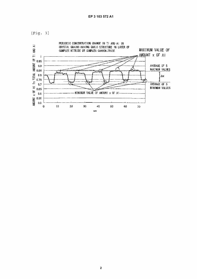
35
40
45
50
55
structure. When the average aspect ratio A is higher than 10, it is difficult to suppress the propagation of cracks. Inaddition, when the average grain width W is smaller than 0.1 mm, wear resistance decreases. When the average grainwidth W is greater than 2.0 mm, toughness decreases. Therefore, the average grain width W of the crystal grains havingan NaCl type face-centered cubic structure included in the layer of a complex nitride or complex carbonitride was selectedto be 0.1 mm to 2.0 mm.
Compositional Variation in Ti and Al Present in Crystal grains Having NaCl Type Face-Centered Cubic Structure
[0032] Furthermore, in a case where crystals having an NaCl type face-centered cubic structure are expressed by thecomposition formula: (Ti1-xAlx)(CyN1-y), when a periodic compositional variation in Ti and Al is present in crystal grains,strain occurs in the crystal grains, resulting in an improvement in hardness. However, when the difference Δx betweenthe average of maximum values of x and the average of minimum values thereof in the composition formula, which isan index of the degree of the compositional variation in Ti and Al, is smaller than 0.03, the degree of strain in the crystalgrains described above is low, and a sufficient improvement in hardness cannot be expected. On the other hand, whenthe difference Δx between the average of the maximum values of x and the average of the minimum values thereof isgreater than 0.25, the degree of strain in the crystal grains becomes too high, there are more lattice defects, and hardnessdecreases. Here, regarding the compositional variation in Ti and Al present in the crystal grains having an NaCl typeface-centered cubic structure, the difference Δx between the average of the maximum values of x which varies periodicallyand the average of the minimum values thereof selected to be 0.05 to 0.25.[0033] In addition, it is preferable that a periodic compositional variation in Ti and Al is present along one orientationamong equivalent crystal orientations expressed by <001> of the crystal grains having an NaCl type face-centered cubicstructure. However, when the period thereof is smaller than 3 nm, toughness decreases. On the other hand, when theperiod is greater than 100 nm, the effect of improving hardness cannot be expected. Therefore, it is preferable that theperiod that is present along one orientation among equivalent crystal orientations expressed by <001> of cubic crystalgrains is 3 nm to 100 nm. In addition, when a change in the amount XO of Al in the total amount of Ti and Al in a planeorthogonal to the orientation is 0.01 or lower, dislocation slip in a {001} plane at an angle with respect to the {111} planeis induced, resulting in an improvement in toughness.
Lattice Constants a of Crystal grains Having NaCl Type Face-Centered Cubic Structure Included in Layer of Complex Nitride or Complex Carbonitride
[0034] An X-ray diffraction test was performed on the layer of a complex nitride or complex carbonitride using an X-ray diffraction apparatus and Cu-Kα radiation as a radiation source and the lattice constants a of the crystal grains havingan NaCl type face-centered cubic structure were obtained. When the lattice constants a of the crystal grains satisfy arelationship of 0.05aTiN + 0.95aAlN ≤ a ≤ 0.4aTiN + 0.6aAlN for the lattice constant aTiN: 4.24173 A of cubic TiN (JCPDS00-038-1420) and the lattice constant aAlN: 4.045 A of cubic AlN (JCPDS 00-046-1200), higher hardness is exhibited,and high thermal conductivity is exhibited. Therefore, in addition to excellent wear resistance, excellent thermal shockresistance is provided.
Fine Crystal Grains Present in Grain Boundaries of Columnar Structure Constituted by Individual Crystal grains Having NaCl Type Face-Centered Cubic Structure in Layer of Complex Nitride or Complex Carbonitride, and Area proportion and Average Grain Size R of Fine Grains:
[0035] Since fine crystal grains having a hexagonal structure are present in grain boundaries of a columnar structureconstituted by the individual crystal grains having an NaCl type face-centered cubic structure, grain boundary sliding issuppressed, resulting in an improvement in toughness. However, when the area proportion thereof is higher than 30%by area, the proportion of crystal phases having an NaCl type face-centered cubic structure is relatively decreased andthus hardness decreases, which is not preferable. In addition, when the average grain size R of the fine crystal grainsis smaller than 0.01 mm, an effect of suppressing grain boundary sliding is insufficient. When the average grain size Rthereof is greater than 0.3 mm, strain in the columnar structure increases and thus hardness decreases, which is notpreferable.
Lower Layer and Upper Layer
[0036] The layer of a complex nitride or complex carbonitride of the present invention exhibits sufficient effects in itself.However, in a case where the lower layer which is formed of a Ti compound layer that includes one layer or two or morelayers of a Ti carbide layer, a Ti nitride layer, a Ti carbonitride layer, a Ti oxycarbide layer, and a Ti oxycarbonitride layerand has an average total layer thickness of 0.1 mm to 20 mm is provided, and/or in a case where the upper layer which
EP 3 103 572 A1
9
5
10
15
20
25
30
35
40
45
50
55
includes an aluminum oxide layer having an average layer thickness of 1 mm to 25 mm is provided, together with theeffects of these layers, better characteristics can be created. In a case where the lower layer which is formed of a Ticompound layer that includes one layer or two or more layers of a Ti carbide layer, a Ti nitride layer, a Ti carbonitridelayer, a Ti oxycarbide layer, and a Ti oxycarbonitride layer is provided, when the average total layer thickness of thelower layer is smaller than 0.1 mm, the effect of the lower layer is insufficiently exhibited. On the other hand, when theaverage total layer thickness thereof is greater than 20 mm, the crystal grains easily coarsen and chipping easily occurs.In addition, when the average total layer thickness of the upper layer including an aluminum oxide layer is smaller than1 mm, the effect of the lower layer is insufficiently exhibited. On the other hand, when the average total layer thicknessthereof is greater than 25 mm, the crystal grains easily coarsen and chipping easily occurs.
Advantageous Effects of Invention
[0037] In the present invention, the surface-coated cutting tool provided with the hard coating layer on the surface ofthe tool body has a configuration unique to the present invention in which the hard coating layer includes at least thelayer of a complex nitride or complex carbonitride of Ti and Al, which is formed by a chemical vapor deposition methodand has an average layer thickness of 1 mm to 20 mm, in a case where the layer is expressed by the composition formula:(Ti1-xAlx)(CyN1-y), the average amount Xavg of Al in the total amount of Ti and Al and the average amount Yavg of C inthe total amount of C and N (both Xavg and Yavg are atomic ratios) respectively satisfy 0.60 ≤ Xavg ≤ 0.95 and 0 ≤Yavg ≤ 0.005, crystal grains having an NaCl type face-centered cubic structure are present among crystal grains con-stituting the layer of a complex nitride or complex carbonitride, in a case where the crystal orientations of the crystalgrains are analyzed in the longitudinal sectional direction thereof using an electron backscatter diffraction apparatus,when an inclined angle frequency distribution is obtained by measuring the inclined angles of normal lines of {111} planeswhich are the crystal planes of the crystal grains with respect to the normal direction of the surface of the tool body,dividing inclined angles in a range of 0 degrees to 45 degrees with respect to the normal direction among the measuredinclined angles into intervals of 0.25 degrees, and aggregating frequencies in the respective divisions, a highest peakis present in an inclined angle division in a range of 0 degrees to 10 degrees and the sum of frequencies that are presentin the range of 0 degrees to 10 degrees has a proportion of 45% or higher of the total of the frequencies in the inclinedangle frequency distribution, regarding the layer of a complex nitride or complex carbonitride, in a case where the layeris observed in the longitudinal sectional direction, a columnar structure in which the average grain width W of the individualcrystal grains having an NaCl type face-centered cubic structure in the layer of a complex nitride or complex carbonitrideis 0.1 mm to 2.0 mm and the average aspect ratio A thereof is 2 to 10 is included, and in the crystal grains having anNaCl type face-centered cubic structure, a periodic compositional variation in Ti and Al in the composition formula:(Ti1-xAlx)(CyN1-y) is present along the layer thickness direction of the layer of a complex nitride or complex carbonitride,and the difference Δx between the average of maximum values of x which varies periodically and the average of minimumvalues thereof is 0.03 to 0.25, whereby strain is introduced into the crystal grains having a cubic structure. Therefore,the hardness of the grains is improved, and the toughness thereof is improved while high wear resistance is maintained.As a result, the effect of improving chipping resistance is exhibited, excellent cutting performance is exhibited duringlong-term use compared to a hard coating layer in the related art, and thus an increase in the service life of the coatedtool is achieved.[0038] Particularly, in the crystal grains having an NaCl type face-centered cubic structure in the layer of a complexnitride or complex carbonitride of Ti and Al, a periodic compositional variation in Ti and Al is present in the crystal grains,and thus strain is introduced into crystal grains, resulting in improvement in hardness. In addition, since the columnarstructure is included, high wear resistance is exhibited. At the same time, since the fine crystal grains having a hexagonalstructure are present in the crystal grain boundaries of the columnar structure, grain boundary sliding is insufficient,resulting in an improvement in toughness. Furthermore, since the crystal grains having an NaCl type face-centered cubicstructure are aligned with {111} planes, both flank wear resistance and crater wear resistance are improved. Moreover,the coated tool of the present invention exhibits excellent wear resistance as well as chipping resistance and defectresistance even in a case of being used for high-speed intermittent cutting work of alloy steel or the like during whichintermittent and impact loads are exerted on a cutting edge.
Brief Description of Drawings
[0039]
Fig. 1 is a film configuration schematic view schematically illustrating the section of a layer of a complex nitride orcomplex carbonitride of Ti and Al included in a hard coating layer of the present invention.Fig. 2 is a schematic view schematically illustrating that, in crystal grains having an NaCl type face-centered cubicstructure in which a periodic compositional variation in Ti and Al is present in the section of a layer of a complex
EP 3 103 572 A1
10
5
10
15
20
25
30
35
40
45
50
55
nitride or complex carbonitride of Ti and Al included in a hard coating layer corresponding to an embodiment of thepresent invention, the periodic compositional variation in Ti and Al is present along one orientation among equivalentcrystal orientations expressed by <001> of the crystal grains, and the periodic compositional variation in Ti and Alin a plane orthogonal to the orientation is small.Fig. 3 shows an example of a graph of a periodic compositional variation x in Ti and Al as a result of line analysisperformed by energy-dispersive X-ray spectroscopy (EDS) using a transmission electron microscope on the crystalgrains having an NaCl type face-centered cubic structure in which the periodic compositional variation in Ti and Alis present in the section of the layer of a complex nitride or complex carbonitride of Ti and Al included in the hardcoating layer corresponding to the embodiment of the present invention.Fig. 4 shows an example of an inclined angle frequency distribution which is obtained by measuring inclined anglesof normal lines of {111} planes which are crystal planes of the crystal grains with respect to a normal direction ofthe surface of a tool body in the section of a layer of a complex nitride or complex carbonitride of Ti and Al includedin a hard coating layer of a present invention coated tool, dividing inclined angles in a range of 0 degrees to 45degrees with respect to the normal direction among the measured inclined angles into intervals of 0.25 degrees,and aggregating frequencies in the respective divisions.Fig. 5 shows an example of an inclined angle frequency distribution which is obtained by measuring inclined anglesof normal lines of {111} planes which are crystal planes of the crystal grains with respect to a normal direction ofthe surface of a tool body in the section of a layer of a complex nitride or complex carbonitride of Ti and Al includedin a hard coating layer of an inclined angle frequency distribution, dividing inclined angles in a range of 0 degreesto 45 degrees with respect to the normal direction among the measured inclined angles into intervals of 0.25 degrees,and aggregating frequencies in the respective divisions.
Description of Embodiments
[0040] Next, Examples of the coated tool of the present invention will be described in more detail.
Example 1
[0041] As raw material powders, a WC powder, a TiC powder, a TaC powder, an NbC powder, a Cr3C2 powder, anda Co powder, all of which had an average grain size of 1 mm to 3 mm, were prepared, and the raw material powderswere mixed in mixing compositions shown in Table 1. Wax was further added thereto, and the mixture was blended inacetone by a ball mill for 24 hours and was decompressed and dried. Thereafter, the resultant was press-formed intocompacts having predetermined shapes at a pressure of 98 MPa, and the compacts were sintered in a vacuum at 5 Paunder the condition that the compacts were held at a predetermined temperature in a range of 1370°C to 1470°C forone hour. After the sintering, tool bodies A to C made of WC-based cemented carbide with insert shapes according toISO standard SEEN1203AFSN were produced.[0042] In addition, as raw material powders, a TiCN (TiC/TiN = 50/50 in terms of mass ratio) powder, an Mo2C powder,a ZrC powder, an NbC powder, a WC powder, a Co powder, and an Ni powder, all of which had an average grain sizeof 0.5 mm to 2 mm, were prepared, and the raw material powders were mixed in mixing compositions shown in Table 2,were subjected to wet mixing by a ball mill for 24 hours, and were dried. Thereafter, the resultant was press-formed intocompacts at a pressure of 98 MPa, and the compacts were sintered in a nitrogen atmosphere at 1.3 kPa under thecondition that the compacts were held at a temperature of 1500°C for one hour. After the sintering, a tool body D madeof TiCN-based cermet with insert shapes according to ISO standard SEEN1203AFSN was produced.[0043] Next, present invention coated tools 1 to 9 were produced by forming hard coating layers, which included a(Ti1-xAlx)(CyN1-y) layer in which crystal grains having an NaCl type face-centered cubic structure with a periodic com-positional variation in Ti and Al shown in Table 7 were present in an area proportion shown in Table 7 and which had atarget layer thickness shown in Table 7, on the surfaces of the tool bodies A to D through a thermal CVD method for apredetermined time using a chemical vapor deposition apparatus
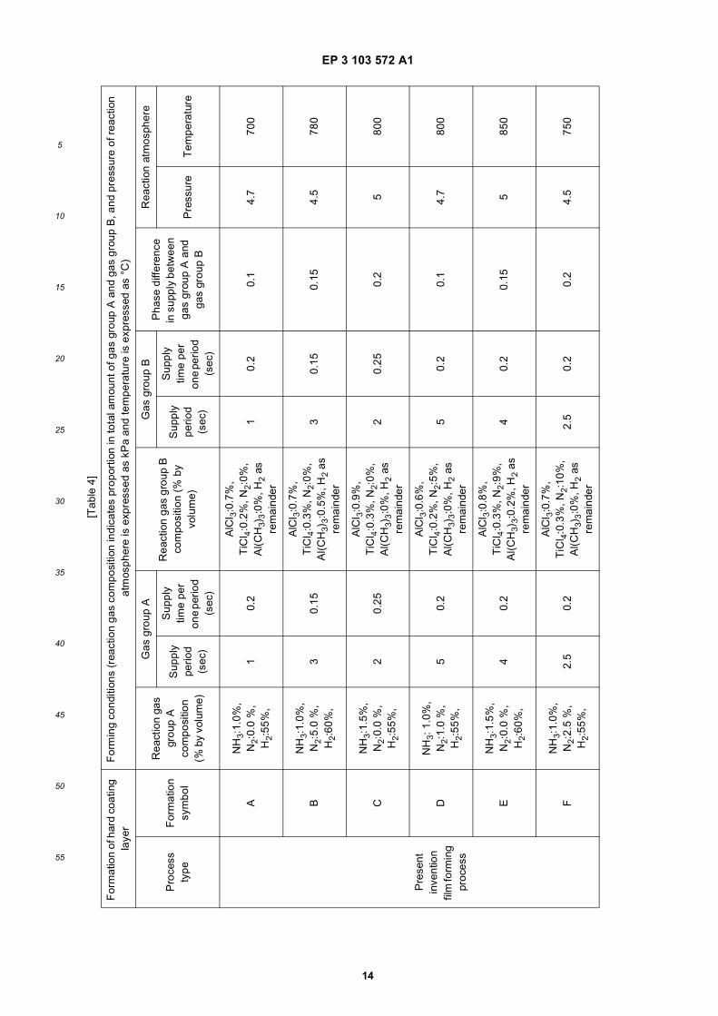
(a) under forming conditions A to J shown in Table 4 in which a gas group A of NH3 and H2 and a gas group B ofTiCl4, Al(CH3)3, AlCl3, NH3, N2, and H2 were used and in each gas supply method, a reaction gas composition (%by volume with respect to the total amount of the gas group A and the gas group B) included a gas group A of NH3:1.0% to 1.5%, N2: 0.0% to 5.0%, H2: 55% to 60% and a gas group B of AlCl3: 0.6% to 0.9%, TiCl4: 0.2% to 0.3%,Al(CH3)3: 0% to 0.5%, N2: 0.0% to 12.0%, H2: the remainder, a reaction atmosphere pressure was 4.5 kPa to 5.0kPa, a reaction atmosphere temperature was 700°C to 900°C, a supply period was 1 second to 5 seconds, a gassupply time per one period was 0.15 seconds to 0.25 seconds, and a phase difference between gas supply A andgas supply B was 0.10 seconds to 0.20 seconds.

EP 3 103 572 A1
11
5
10
15
20
25
30
35
40
45
50
55
[0044] In addition, any of a lower layer and an upper layer shown in Table 6 was formed on the present inventioncoated tools 3 to 9 under forming conditions shown in Table 3.[0045] Regarding a layer of a complex nitride or complex carbonitride of Ti and Al included in the hard coating layersof the present invention coated tools 1 to 15, a plurality of visual fields were observed using a scanning electron microscope(at a magnification of 5000x and 20,000x). As illustrated in a film configuration schematic view in Fig. 1, it was confirmedthat fine crystal grains having a hexagonal structure were present in crystal grain boundaries of a columnar structureconstituted by the crystal grains having an NaCl type face-centered cubic structure, the area proportion thereof was 30or less by area, and the average grain size R of the fine crystal grains was 0.01 mm to 0.3 mm. The average grain sizeR of the fine crystal grains could be obtained by searching a plurality of observation visual fields for three portions havinga grain boundary length of 0.5 mm or greater among the grain boundaries of the columnar structure where the fine crystalgrains were found, counting the number of grain boundaries that were present on a line segment 0.5 mm in each of theportions, and dividing 1.5 mm by the sum of the numbers of grain boundaries in the three portions.[0046] In addition, it was confirmed through line analysis by energy-dispersive X-ray spectroscopy (EDS) using atransmission electron microscope (at a magnification of 200,000x) that a periodic compositional variation of Ti and Alwas present in the crystal grains having an NaCl type face-centered cubic structure. As a result of more detailed analysis,it was confirmed that the difference between the maximum values and the minimum values of the periodic compositionalvariation x in Ti and Al was 0.03 to 0.25.[0047] In addition, for the purpose of comparison, like the present invention coated tools 1 to 9, hard coating layersincluding at least a layer of a complex nitride or complex carbonitride of Ti and Al were deposited on the surfaces of thetool bodies A to D to have a target layer thickness (mm) shown in Fig. 8 under the conditions shown in Tables 3 and 5.At this time, comparative coated tools 1 to 9 were produced by forming the hard coating layers so that the position ofthe reaction gas on the surface of the tool body was not changed over time during a process of forming a (Ti1-xAlx)(CyN1-y)layer.[0048] In addition, like the present invention coated tools 3 to 9, any of a lower layer and an upper layer shown inTable 6 was formed on the comparative coated tools 3 to 9 under the forming conditions shown in Table 3.[0049] For reference, a reference coated tool 10 shown in Table 8 was produced by depositing (Ti1-xAlx)(CyN1-y) layersof a reference example on the surfaces of the tool body B and the tool body C to have target layer thicknesses througharc ion plating using a physical vapor deposition apparatus in the related art. In addition, conditions of the arc ion platingusing the deposition of the reference example are as follows.
(a) The tool bodies B and C were subjected to ultrasonic cleaning in acetone and were dried. In this state, the toolbodies B and C were mounted along outer circumferential portions on a rotating table in an arc ion plating apparatusat positions distant from the center axis thereof by predetermined distances in a radial direction thereof, and an Al-Ti alloy having a predetermined composition was disposed as a cathode electrode (evaporation source).(b) First, while the inside of the apparatus was evacuated and maintained in a vacuum at 10-2 Pa or lower, the insideof the apparatus was heated to 500°C by a heater, and a DC bias voltage of -1000 V was thereafter applied to thetool body that was rotated while being revolved on the rotating table. In addition, arc discharge was generated byallowing a current of 200 A to flow between the cathode electrode made of the Al-Ti alloy and an anode electrodesuch that Al and Ti ions were generated in the apparatus and the surface of the tool body was subjected to bombardcleaning.(c) Next, nitrogen gas as a reaction gas was introduced into the apparatus to form a reaction atmosphere at 4 Pa,and a DC bias voltage of -50 V was applied to the tool body that was rotated while being revolved on the rotatingtable. In addition, arc discharge was generated by allowing a current of 120 A to flow between the cathode electrode(evaporation source) made of the Al-Ti alloy and the anode electrode such that a (Ti,Al)N layer having a targetcomposition and a target layer thickness shown in Table 8 was deposited on the surface of the tool body, therebyproducing the reference coated tool 10.
[0050] The section of each of constituent layers of the present invention coated tools 1 to 9, the comparative coatedtools 1 to 9, and the reference coated tool 10 was measured using a scanning electron microscope (at a magnificationof 5000x). An average layer thickness was obtained by measuring and averaging the layer thicknesses of five points inan observation visual field. All of the results showed substantially the same average layer thicknesses as the target layerthicknesses shown in Tables 6 to 8.[0051] In addition, regarding the average amount Xavg of Al of the layer of a complex nitride or complex carbonitride,a sample of which the surface was polished using an electron probe micro-analyzer (EPMA) was irradiated with electronbeams from the sample surface side, and the average amount Xavg of Al was obtained by averaging 10 points of theanalytic result of obtained characteristic X-rays. The average amount Yavg of C was obtained by secondary ion massspectrometry (SIMS). Ion beams were emitted toward a range of 70 mm 3 70 mm from the sample surface side, andthe concentration of components emitted by a sputtering action was measured in a depth direction. The average amount

EP 3 103 572 A1
12
5
10
15
20
25
30
35
40
45
50
55
Yavg of C represents the average value in the depth direction of the layer of a complex nitride or complex carbonitrideof Ti and Al. However, the amount of C excludes an unavoidable amount of C which is included even though gascontaining C is not intentionally used as a gas raw material. Specifically, the amount (atomic ratio) of the component Ccontained in the layer of a complex nitride or complex carbonitride in a case where the amount of supplied Al(CH3)3 wasset to 0 was obtained as the unavoidable amount of C, and a value obtained by subtracting the unavoidable amount ofC from the amount (atomic ratio) of the component C contained in the layer of a complex nitride or complex carbonitrideobtained in a case where Al(CH3)3 was intentionally supplied was selected to be Yavg.[0052] In addition, regarding the present invention coated tools 1 to 9, the comparative coated tools 1 to 9, and thereference coated tool 10, in the individual crystal grains which were present in a range at a length of 10 mm in a directionparallel to the surface of the tool body in less than the film thickness of the layer of a complex nitride or complexcarbonitride in a normal direction thereof and had an NaCl type face-centered cubic structure in the (Ti1-xAlx) (CyN1-y)layer included in the layer of a complex nitride or complex carbonitride, grain widths w in the direction parallel to thesurface of the body and grain lengths 1 in the direction perpendicular to the surface of the body were measured from asectional direction in the direction perpendicular to the tool body using a scanning electron microscope (at a magnificationof 5000x and 20,000x), the aspect ratio a(= l/w) of each of the crystal grains was calculated, the average value of theaspect ratios a obtained for the individual crystal grains was calculated as an average aspect ratio A, and the averagevalue of the grain widths w obtained for the individual crystal grains was calculated as an average grain width W.Furthermore, the average grain size R of fine crystal grains that were present in the grain boundaries of a columnarstructure constituted by the individual crystal grains having a cubic structure was also calculated. The results are shownin Tables 7 and 8.[0053] In addition, regarding an inclination angle frequency distribution of the hard coating layer, in a state where thesection of the hard coating layer including the layer of a complex nitride or complex carbonitride of Ti and Al in thedirection perpendicular to the surface of the tool body was polished as a polished surface, the polished surface was setin the body tube of a field emission scanning electron microscope, and an electron beam was emitted toward each ofthe crystal grains having a cubic crystal lattice, which were present in a measurement range of the section polishedsurface at an incident angle of 70 degrees with respect to the section polished surface at an acceleration voltage of 15kV and an emission current of 1 nA. Regarding the hard coating layer in a measurement range at a length of 100 mmin the direction parallel to the surface of the tool body in less than the film thickness along the section in the directionperpendicular to the surface of the tool body, inclined angles of normal lines of {111} planes which were crystal planesof the crystal grains with respect to the normal line (the direction perpendicular to the surface of the body in the sectionpolished surface) of the surface of the body were measured using an electron backscatter diffraction imaging device atan interval of 0.01 mm/step. On the basis of the measurement results, measured inclined angles in a range of 0 degreesto 45 degrees among the measured inclined angles were divided into intervals of 0.25 degrees, frequencies in therespective divisions were aggregated, and the presence of the peaks of the frequencies present in a range of 0 degreesto 10 degrees was checked. In addition, the proportion of the frequencies present in the range of 0 degrees to 10 degreeswas obtained. The results are also shown in Tables 7 and 8.[0054] As an example, Fig. 4 shows an inclined angle frequency distribution measured for the present invention coatedtools, and Fig. 5 shows an inclined angle frequency distribution graph measured for the comparative coated tools.[0055] In addition, in a state where the section of the hard coating layer including the layer of a complex nitride orcomplex carbonitride of Ti and Al in the direction perpendicular to the surface of the tool body was polished as a polishedsurface, the polished surface was set in the body tube of the field emission scanning electron microscope, and an electronbeam was emitted toward each of the crystal grains which were present in the measurement range of the section polishedsurface at an incident angle of 70 degrees with respect to the section polished surface at an acceleration voltage of 15kV and an emission current of 1 nA. Regarding the hard coating layer in a range at a length of 50 mm in the directionparallel to the tool body in less than the layer thickness of the layer of a complex nitride or complex carbonitride in thenormal direction thereof, an electron backscatter diffraction image was measured using an electron backscatter diffractionapparatus device at an interval of 0.01 mm/step. By analyzing the crystal structure of the individual crystal grains, finecrystal grains that were present in the grain boundaries of a columnar structure constituted by the crystal grains havingan NaCl type face-centered cubic structure were identified as a hexagonal structure, and the area proportion of the finecrystal grains was obtained. The results are also shown in Tables 7 and 8.[0056] Furthermore, a small region of the layer of a complex nitride or complex carbonitride was observed by usingthe transmission electron microscope (at a magnification of 200,000x), and line analysis from the section side wasperformed using energy-dispersive X-ray spectroscopy (EDS). It was confirmed that a periodic compositional variationin Ti and Al was present in the composition formula: (Ti1-xAlx)(CyN1-y) in the crystal grains having an NaCl type face-centered cubic structure. In addition, through electron diffraction of the crystal grains, it was confirmed that the periodiccompositional variation in Ti and Al was present along one orientation among equivalent crystal orientations expressedby <001> of the crystal grains having an NaCl type face-centered cubic structure. Line analysis through EDS along theorientation was performed, the difference between the average of maximum values of the periodic compositional variation

EP 3 103 572 A1
13
5
10
15
20
25
30
35
40
45
50
55
in Ti and Al and the average of minimum values thereof was obtained as Δx, and furthermore, the period of the maximumvalues was obtained as the period of the periodic compositional variation in Ti and Al. Line analysis along a directionorthogonal to the orientation was performed, and the difference between the maximum value and the minimum valueof the amount x of Al in the total amount of Ti and Al was obtained as a compositional variation XO in Ti and Al.[0057] The results are also shown in Tables 7 and 8.
[Table 1]
TypeMixing composition (mass%)
Co TiC TaC NbC Cr3C2 WC
Tool body
A 8.0 1.5 - 3.0 0.4 Remainder
B 8.5 - 1.8 0.2 - Remainder
C 7.0 - - - - Remainder
[Table 2]
TypeMixing composition (mass%)
Co Ni ZrC NbC Mo2C WC TiCN
Tool body D 8 5 1 6 6 10 Remainder
[Table 3]
Constituent layers of hard coating layerForming conditions (pressure of reaction atmosphere is expressed
as kPa and temperature is expressed as °C)
TypeFormation
symbolReaction gas composition (%
by volume)Reaction atmosphere
Pressure Temperature
(Ti1-xAlx)(CyN1-y) layer
TiAlCN TiAlCN See Tables 4 and 5
Ti compound layer
TiC TiCTiCl4:4.0%, CH4:7.5%,
H2:remainder7 1000
TiN TiNTiCl4:4.0%, N2:30%,
H2:remainder30 780
TiCN TiCNTiCl4:2%, CH3CN:0.7%, N2:10%, H2:remainder
7 780
TiCNO TiCNOTiCl4:1%, CO:0.5%, CO2:1%,
CH3CN:1%, N2:10%, H2:remainder
7 780
Al2O3 layer Al2O3 Al2O3
AlCl3:1.2%, CO2:5.5%, HCl:2.2%, H2S:0.2%,
H2:remainder7 800
EP 3 103 572 A1
14
5
10
15
20
25
30
35
40
45
50
55
[Tab
le 4
]
For
mat
ion
of h
ard
coat
ing
laye
rF
orm
ing
cond
ition
s (r
eact
ion
gas
com
posi
tion
indi
cate
s pr
opor
tion
in to
tal a
mou
nt o
f gas
gro
up A
and
gas
gro
up B
, and
pre
ssur
e of
rea
ctio
n at
mos
pher
e is
exp
ress
ed a
s kP
a an
d te
mpe
ratu
re is
exp
ress
ed a
s °C
)
Pro
cess
ty
peF
orm
atio
n sy
mbo
l
Rea
ctio
n ga
s gr
oup
A
com
posi
tion
(% b
y vo
lum
e)
Gas
gro
up A
Rea
ctio
n ga
s gr
oup
B
com
posi
tion
(% b
y vo
lum
e)
Gas
gro
up B
Pha
se d
iffer
ence
in
sup
ply
betw
een
gas
grou
p A
and
ga
s gr
oup
B
Rea
ctio
n at
mos
pher
e
Sup
ply
perio
d (s
ec)
Sup
ply
time
per
one
perio
d (s
ec)
Sup
ply
perio
d (s
ec)
Sup
ply
time
per
one
perio
d (s
ec)
Pre
ssur
eT
empe
ratu
re
AN
H3:
1.0%
, N
2:0.
0 %
, H
2:55
%,
10.
2
AlC
l 3:0
.7%
, T
iCl 4
:0.2
%, N
2:0%
, A
l(CH
3)3:0
%, H
2 as
re
mai
nder
10.
20.
14.
770
0
BN
H3:
1.0%
, N
2:5.
0 %
, H
2:60
%,
30.
15
AlC
l 3:0
.7%
, T
iCl 4
:0.3
%, N
2:0%
, A
l(CH
3)3:
0.5%
, H2
as
rem
aind
er
30.
150.
154.
578
0
CN
H3:
1.5%
, N
2:0.
0 %
, H
2:55
%,
20.
25
AlC
l 3:0
.9%
, T
iCl 4
:0.3
%, N
2:0%
, A
l(CH
3)3:0
%, H
2 as
re
mai
nder
20.
250.
25
800
Pre
sent
in
vent
ion
film
form
ing
proc
ess
DN
H3:
1.0
%,
N2:
1.0
%,
H2:
55%
,5
0.2
AlC
l 3:0
.6%
, T
iCl 4
:0.2
%, N
2:5%
, A
l(CH
3)3:0
%, H
2 as
re
mai
nder
50.
20.
14.
780
0
EN
H3:
1.5%
, N
2:0.
0 %
, H
2:60
%,
40.
2
AlC
l 3:0
.8%
, T
iCl 4
:0.3
%, N
2:9%
, A
l(CH
3)3:
0.2%
, H2
as
rem
aind
er
40.
20.
155
850
FN
H3:
1.0%
, N
2:2.
5 %
, H
2:55
%,
2.5
0.2
AlC
l 3:0
.7%
, T
iCl 4
:0.3
%, N
2:10
%,
Al(C
H3)
3:0
%, H
2 as
re
mai
nder
2.5
0.2
0.2
4.5
750

EP 3 103 572 A1
15
5
10
15
20
25
30
35
40
45
50
55
(con
tinue
d)
For
mat
ion
of h
ard
coat
ing
laye
rF
orm
ing
cond
ition
s (r
eact
ion
gas
com
posi
tion
indi
cate
s pr
opor
tion
in to
tal a
mou
nt o
f gas
gro
up A
and
gas
gro
up B
, and
pre
ssur
e of
rea
ctio
n at
mos
pher
e is
exp
ress
ed a
s kP
a an
d te
mpe
ratu
re is
exp
ress
ed a
s °C
)
Pro
cess
ty
peF
orm
atio
n sy
mbo
l
Rea
ctio
n ga
s gr
oup
A
com
posi
tion
(% b
y vo
lum
e)
Gas
gro
up A
Rea
ctio
n ga
s gr
oup
B
com
posi
tion
(% b
y vo
lum
e)
Gas
gro
up B
Pha
se d
iffer
ence
in
sup
ply
betw
een
gas
grou
p A
and
ga
s gr
oup
B
Rea
ctio
n at
mos
pher
e
Sup
ply
perio
d (s
ec)
Sup
ply
time
per
one
perio
d (s
ec)
Sup
ply
perio
d (s
ec)
Sup
ply
time
per
one
perio
d (s
ec)
Pre
ssur
eT
empe
ratu
re
GN
H3:
1.0%
, N
2:0.
0 %
, H
2:60
%,
1.5
0.15
AlC
l 3:0
.8%
, T
iCl 4
:0.2
%, N
2:12
%,
Al(C
H3)
3:0
%, H
2 as
re
mai
nder
1.5
0.15
0.2
4.7
800
HN
H3:
1.0%
, N
2:3
.51.
20.
25A
lCl 3
:0.9
%,
TiC
l 4:0
.2%
,1.
20.
250.
14.
790
0
%, H
2:60
%,
N2:3
%, A
l(CH
3)3:0
%,
H2 a
s re
mai
nder
IN
H3:
1.5%
, N
2:0.
0 %
, H
2:55
%,
4.5
0.2
AlC
l 3:0
.6%
, T
iCl 4
:0.3
%, N
2:7%
, A
l(CH
3)3:0
%, H
2 as
re
mai
nder
4.5
0.2
0.15
4.7
800

EP 3 103 572 A1
16
5
10
15
20
25
30
35
40
45
50
55
[Tab
le 5
]
For
mat
ion
of h
ard
coat
ing
laye
rF
orm
ing
cond
ition
s (r
eact
ion
gas
com
posi
tion
indi
cate
s pr
opor
tion
in to
tal a
mou
nt o
f gas
gro
up A
and
gas
gro
up B
, and
pre
ssur
e of
reac
tion
atm
osph
ere
is e
xpre
ssed
as
kPa
and
tem
pera
ture
is e
xpre
ssed
as
°C)
Pro
cess
type
For
mat
ion
sym
bol
Rea
ctio
n ga
s gr
oup
A
com
posi
tion
(%
by v
olum
e)
Gas
gro
up A
Rea
ctio
n ga
s gr
oup
B
com
posi
tion
(% b
y vo
lum
e)
Gas
BP
hase
di
ffere
nce
in
supp
ly b
etw
een
gas
grou
p A
and
ga
s gr
oup
B
Rea
ctio
n at
mos
pher
e
Sup
ply
perio
d (s
ec)
Sup
ply
time
per
one
perio
d (s
ec)
Sup
ply
perio
d (s
ec)
Sup
ply
time
per
one
perio
d (s
ec)
Pre
ssur
eT
empe
ratu
re
A’
NH
3:1.
0%, N
2:0
. 0%
, H2:
55%
,-
-
AlC
l 3:0
.7%
, T
iCl 4
:0.2
%, N
2:0%
, A
l(CH
3) 3
:0%
, H2
as
rem
aind
er
--
-4.
770
0
B’
NH
3:1.
0%, N
2:5
. 0%
, H2:
60%
,-
-
AlC
l 3:0
.7%
, T
iCl 4
:0.3
%, N
2:0%
, A
l(CH
3) 3
:0%
, H2
as
rem
aind
er
--
-4.
578
0
C’
NH
3:1.
5%, N
2:0
. 0%
, H2:
55%
,-
-
AlC
l 3:0
.9%
, T
iCl 4
:0.3
%, N
2:0%
, A
l(CH
3)3:0
.5%
, H2
as
rem
aind
er
--
-5
800
Com
para
tive
film
form
ing
proc
ess
D’
NH
3:1.
0%, N
2:1
. 0%
, H2:
55%
,-
-
AlC
l 3:0
.6%
, T
iCl 4
:0.2
%, N
2:5%
, A
l(CH
3) 3
:0%
, H2
as
rem
aind
er
--
-4.
780
0
E’
NH
3:1.
5%, N
2:3
. 0%
, H2:
60%
,-
-
AlC
l 3:0
.8%
, T
iCl 4
:0.3
%, N
2:9%
, A
l(CH
3) 3
:0%
, H2
as
rem
aind
er
--
-5
850
F’
NH
3:1.
0%, N
2:2
. 5%
, H2:
55%
,-
-
AlC
l 3:0
.7%
, T
iCl 4
:0.3
%, N
2:1
0%,
Al(C
H3)
3:0
.2%
, H2
as
rem
aind
er
--
-4.
575
0

EP 3 103 572 A1
17
5
10
15
20
25
30
35
40
45
50
55
(con
tinue
d)
For
mat
ion
of h
ard
coat
ing
laye
rF
orm
ing
cond
ition
s (r
eact
ion
gas
com
posi
tion
indi
cate
s pr
opor
tion
in to
tal a
mou
nt o
f gas
gro
up A
and
gas
gro
up B
, and
pre
ssur
e of
reac
tion
atm
osph
ere
is e
xpre
ssed
as
kPa
and
tem
pera
ture
is e
xpre
ssed
as
°C)
Pro
cess
type
For
mat
ion
sym
bol
Rea
ctio
n ga
s gr
oup
A
com
posi
tion
(%
by v
olum
e)
Gas
gro
up A
Rea
ctio
n ga
s gr
oup
B
com
posi
tion
(% b
y vo
lum
e)
Gas
BP
hase
di
ffere
nce
in
supp
ly b
etw
een
gas
grou
p A
and
ga
s gr
oup
B
Rea
ctio
n at
mos
pher
e
Sup
ply
perio
d (s
ec)
Sup
ply
time
per
one
perio
d (s
ec)
Sup
ply
perio
d (s
ec)
Sup
ply
time
per
one
perio
d (s
ec)
Pre
ssur
eT
empe
ratu
re
G’
NH
3:1.
0%, N
2:0
. 0%
, H2:
60%
,-
-
AlC
l 3:0
.6%
, T
iCl 4
:0.2
%, N
2:1
2%,
Al(C
H3) 3
:0%
, H2
as
rem
aind
er
--
-4.
780
0
H’
NH
3:1.
0%, N
2:3.
--
AlC
l 3:0
.9%
, T
iCl 4
:0.2
%,
--
-4.
790
0
5%, H
2:60
%,
N2:
3%, A
l(CH
3)3:
0%,
H2
as r
emai
nder
I’N
H3:1
.5%
,N2:
2.
0%, H
2:55
%,
--
AlC
l 3:0
.6%
, T
iCl 4
:0.3
%, N
2:7%
, A
l(CH
3)3:0
.4%
, H2
as
rem
aind
er
--
-4.
780
0

EP 3 103 572 A1
18
5
10
15
20
25
30
35
40
45
50
55
[Table 6]
TypeTool body
symbol
Hard coating layer (numerical value at the bottom indicates target average layer thickness (mm))
Lower layer Upper layer
First layerSecond
layerFirst layer
Second layer
1 A - - - -
2 D - - - -
Present invention coated tool, comparative coated tool, reference coated tool
3 B TiN (0.3) - - -
4 C TiN (0.3) - - -
5 A TiN (0.3) - - -
6 D TiN (0.3) - Al2O3 (2) -
7 B TiN (0.3) -TiCNO (0.3)
Al2O3 (1.5)
8 C TiC (0.5) - -
9 A TiN (0.3) TiCN (2) - -

EP 3 103 572 A1
19
5
10
15
20
25
30
35
40
45
50
55
[Tab
le 7
]
Typ
eT
ool
body
sy
mbo
l
Har
d co
atin
g la
yer
Laye
r of
com
plex
nitr
ide
or c
ompl
ex c
arbo
nitr
ide
of T
i and
Al (
Ti 1
-xA
l x)(
CyN
1-y)
For
ma-
tion
sym
-bo
l of
TiA
lCN
fil
m fo
rm-
ing
proc
-es
s (s
ee
Tab
le 4
)
Ave
r-ag
e am
ount
X
avg
of
Al
Ave
r-ag
e am
ount
Y
avg
of
C
Diff
er-
ence
Dx
betw
een
aver
age
of m
axi-
mum
val
-ue
s of
x
and
an
aver
age
of m
ini-
mum
val
-ue
s
Div
isio
n of
in
clin
ed
angl
es in
w
hich
hi
ghes
t pe
ak is
pr
esen
t in
incl
ined
an
gle
fre-
quen
cy
dist
ribu-
tion
(de-
gree
s)
Pro
port
ion
of fr
eque
n-ci
es o
f 0
degr
ees
to
10 d
e-gr
ees
in in
-cl
ined
an-
gle
divi
sion
in
incl
ined
an
gle
fre-
quen
cy
dist
ribu-
tion
(%)
Ave
r-ag
e gr
ain
wid
th W
of
cub
ic
grai
ns
(mm
)
Ave
r-ag
e as
-pe
ct r
a-tio
A o
f cu
bic
grai
ns
Ave
rage
val
-ue
of p
erio
ds
of c
ompo
si-
tiona
l ch
ange
in T
i an
d A
l alo
ng
<00
1> o
rien-
tatio
n (n
m)
Cha
nge
in
aver
age
amou
nt X
O
of A
l in
plan
e or
thog
onal
to
per
iodi
c co
mpo
si-
tiona
l ch
ange
al
ong
<00
1>
orie
ntat
ion
Latti
ce c
on-
stan
t of
grai
ns h
av-
ing
NaC
l ty
pe fa
ce-
cent
ered
cu-
bic
stru
ctur
e (Å
)
Are
a pr
o-po
rtio
n of
he
xago
-na
l fin
e gr
ains
(%
by a
rea)
Ave
rage
gr
ain
size
R
of h
ex-
agon
al
fine
grai
ns
(mm
)
Tar
get
laye
r th
ick-
ness
(m
m)
Pre
sent
in
ven-
tion
coat
ed
tool
1A
A0.
920.
0001
or
less
0.18
3.5
to 3
.75
48.0
0.3
5.00
150.
024.
061
0-
2.5
2D
B0.
650.
004
0.21
6.25
to 6
.550
.00.
28.
0035
0.01
or
less
4.11
40
-6.
5
3B
C0.
870.
0001
or
less
0.12
0.5
to 0
.75
65.0
1.5
3.50
450.
01 o
r le
ss4.
071
0-
4
4C
D0.
830.
0001
or
less
0.10
1.5
to 1
.75
55.0
1.2
4.50
250.
01 o
r le
ss4.
078
0-
3.5
5A
E0.
780.
0018
0.05
1.25
to 1
.568
.00.
83.
0075
0.01
or
less
4.08
815
0.15
5
6D
F0.
680.
0001
or
less
0.14
0 to
0.2
575
.00.
54.
0010
0.01
or
less
4.10
80
-3
7B
G0.
810.
0001
or
less
0.07
1.75
to 2
.070
.00.
95.
0060
0.01
or
less
4.08
20
-6
8C
H0.
750.
0001
or
less
0.04
5 to
5.2
580
.00.
86.
0025
0.01
or
less
4.09
430
.00
0.08
2
9A
I0.
880.
0001
or
less
0.08
8.75
to 9
.068
.01.
92.
2090
0.01
or
less
4.06
90
-4
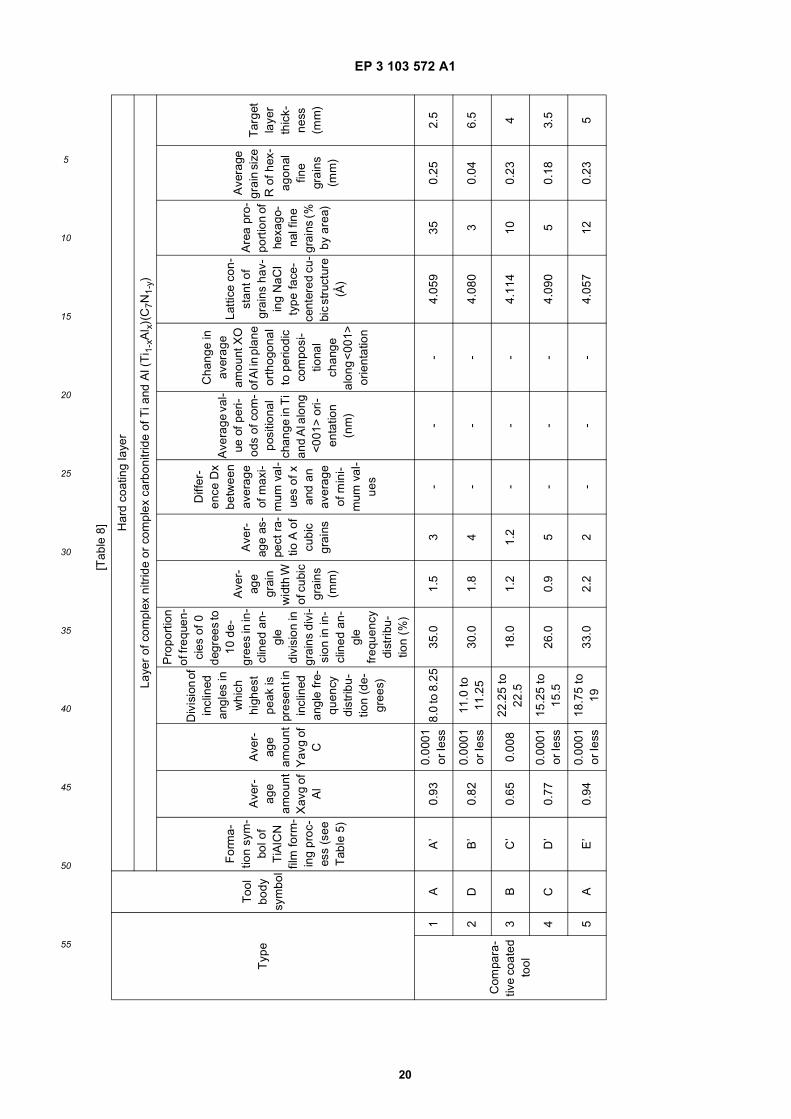
EP 3 103 572 A1
20
5
10
15
20
25
30
35
40
45
50
55
[Tab
le 8
]
Typ
eT
ool
body
sy
mbo
l
Har
d co
atin
g la
yer
Laye
r of
com
plex
nitr
ide
or c
ompl
ex c
arbo
nitr
ide
of T
i and
Al (
Ti 1
-xA
l x)(
C7N
1-y
)
For
ma-
tion
sym
-bo
l of
TiA
lCN
fil
m fo
rm-
ing
proc
-es
s (s
ee
Tab
le 5
)
Ave
r-ag
e am
ount
X
avg
of
Al
Ave
r-ag
e am
ount
Y
avg
of
C
Div
isio
n of
in
clin
ed
angl
es in
w
hich
hi
ghes
t pe
ak is
pr
esen
t in
incl
ined
an
gle
fre-
quen
cy
dist
ribu-
tion
(de-
gree
s)
Pro
port
ion
of fr
eque
n-ci
es o
f 0
degr
ees
to
10 d
e-gr
ees
in in
-cl
ined
an-
gle
divi
sion
in
grai
ns d
ivi-
sion
in in
-cl
ined
an-
gle
freq
uenc
y di
strib
u-tio
n (%
)
Ave
r-ag
e gr
ain
wid
th W
of
cub
ic
grai
ns
(mm
)
Ave
r-ag
e as
-pe
ct r
a-tio
A o
f cu
bic
grai
ns
Diff
er-
ence
Dx
betw
een
aver
age
of m
axi-
mum
val
-ue
s of
x
and
an
aver
age
of m
ini-
mum
val
-ue
s
Ave
rage
val
-ue
of p
eri-
ods
of c
om-
posi
tiona
l ch
ange
in T
i an
d A
l alo
ng
<001
> o
ri-en
tatio
n (n
m)
Cha
nge
in
aver
age
amou
nt X
O
of A
l in
plan
e or
thog
onal
to
per
iodi
c co
mpo
si-
tiona
l ch
ange
al
ong
<00
1>
orie
ntat
ion
Latti
ce c
on-
stan
t of
grai
ns h
av-
ing
NaC
l ty
pe fa
ce-
cent
ered
cu-
bic
stru
ctur
e (Å
)
Are
a pr
o-po
rtio
n of
he
xago
-na
l fin
e gr
ains
(%
by a
rea)
Ave
rage
gr
ain
size
R
of h
ex-
agon
al
fine
grai
ns
(mm
)
Tar
get
laye
r th
ick-
ness
(m
m)
Com
para
-tiv
e co
ated
to
ol
1A
A’
0.93
0.00
01
or le
ss8.
0 to
8.2
535
.01.
53
--
-4.
059
350.
252.
5
2D
B’
0.82
0.00
01
or le
ss11
.0 to
11
.25
30.0
1.8
4-
--
4.08
03
0.04
6.5
3B
C’
0.65
0.00
822
.25
to
22.5
18.0
1.2
1.2
--
-4.
114
100.
234
4C
D’
0.77
0.00
01
or le
ss15
.25
to
15.5
26.0
0.9
5-
--
4.09
05
0.18
3.5
5A
E’
0.94
0.00
01
or le
ss18
.75
to
1933
.02.
22
--
-4.
057
120.
235

EP 3 103 572 A1
21
5
10
15
20
25
30
35
40
45
50
55
(con
tinue
d)
Typ
eT
ool
body
sy
mbo
l
Har
d co
atin
g la
yer
Laye
r of
com
plex
nitr
ide
or c
ompl
ex c
arbo
nitr
ide
of T
i and
Al (
Ti 1
-xA
l x)(
C7N
1-y
)
For
ma-
tion
sym
-bo
l of
TiA
lCN
fil
m fo
rm-
ing
proc
-es
s (s
ee
Tab
le 5
)
Ave
r-ag
e am
ount
X
avg
of
Al
Ave
r-ag
e am
ount
Y
avg
of
C
Div
isio
n of
in
clin
ed
angl
es in
w
hich
hi
ghes
t pe
ak is
pr
esen
t in
incl
ined
an
gle
fre-
quen
cy
dist
ribu-
tion
(de-
gree
s)
Pro
port
ion
of fr
eque
n-ci
es o
f 0
degr
ees
to
10 d
e-gr
ees
in in
-cl
ined
an-
gle
divi
sion
in
grai
ns d
ivi-
sion
in in
-cl
ined
an-
gle
freq
uenc
y di
strib
u-tio
n (%
)
Ave
r-ag
e gr
ain
wid
th W
of
cub
ic
grai
ns
(mm
)
Ave
r-ag
e as
-pe
ct r
a-tio
A o
f cu
bic
grai
ns
Diff
er-
ence
Dx
betw
een
aver
age
of m
axi-
mum
val
-ue
s of
x
and
an
aver
age
of m
ini-
mum
val
-ue
s
Ave
rage
val
-ue
of p
eri-
ods
of c
om-
posi
tiona
l ch
ange
in T
i an
d A
l alo
ng
<001
> o
ri-en
tatio
n (n
m)
Cha
nge
in
aver
age
amou
nt X
O
of A
l in
plan
e or
thog
onal
to
per
iodi
c co
mpo
si-
tiona
l ch
ange
al
ong
<00
1>
orie
ntat
ion
Latti
ce c
on-
stan
t of
grai
ns h
av-
ing
NaC
l ty
pe fa
ce-
cent
ered
cu-
bic
stru
ctur
e (Å
)
Are
a pr
o-po
rtio
n of
he
xago
-na
l fin
e gr
ains
(%
by a
rea)
Ave
rage
gr
ain
size
R
of h
ex-
agon
al
fine
grai
ns
(mm
)
Tar
get
laye
r th
ick-
ness
(m
m)
6D
F’
0.87
0.00
49.
5 to
9.7
525
.01.
61.
2-
--
4.07
128
0.35
3
7B
G’
0.64
0.00
01
or lo
sss
31.2
5 to
31
.526
.00.
83.
5-
--
4.11
616
0.12
6
8C
H’
0.81
0.00
01
or le
ss23
.75
to
2429
.00.
93.
8-
--
4.08
232
0.21
2
9A
I’0.
780.
0025
29.2
5 to
29
.519
.01.
91.
3-
--
4.08
818
.00.
24
Ref
eren
ce
coat
ed to
ol10
BA
IP0.
48-
--
1.2
3.5
--
-4.
147
--
3.5
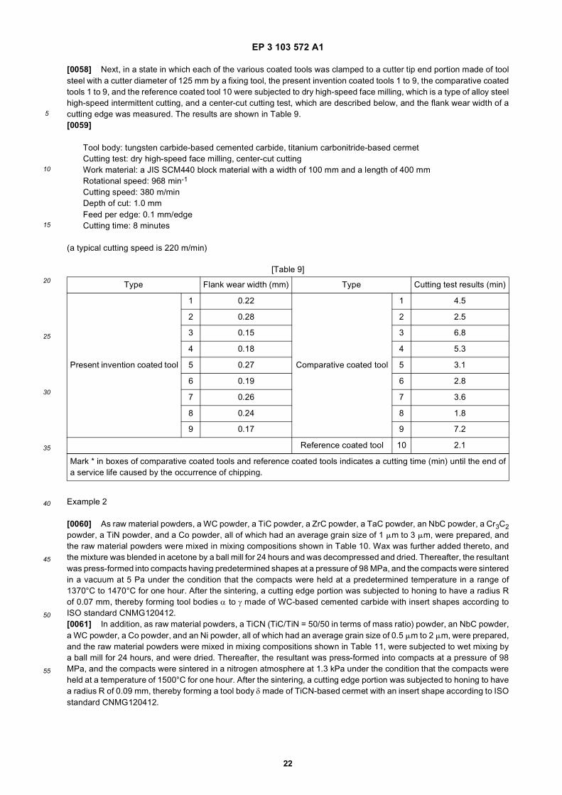
EP 3 103 572 A1
22
5
10
15
20
25
30
35
40
45
50
55
[0058] Next, in a state in which each of the various coated tools was clamped to a cutter tip end portion made of toolsteel with a cutter diameter of 125 mm by a fixing tool, the present invention coated tools 1 to 9, the comparative coatedtools 1 to 9, and the reference coated tool 10 were subjected to dry high-speed face milling, which is a type of alloy steelhigh-speed intermittent cutting, and a center-cut cutting test, which are described below, and the flank wear width of acutting edge was measured. The results are shown in Table 9.[0059]
Tool body: tungsten carbide-based cemented carbide, titanium carbonitride-based cermetCutting test: dry high-speed face milling, center-cut cuttingWork material: a JIS SCM440 block material with a width of 100 mm and a length of 400 mmRotational speed: 968 min-1
Cutting speed: 380 m/minDepth of cut: 1.0 mmFeed per edge: 0.1 mm/edgeCutting time: 8 minutes
(a typical cutting speed is 220 m/min)
Example 2
[0060] As raw material powders, a WC powder, a TiC powder, a ZrC powder, a TaC powder, an NbC powder, a Cr3C2powder, a TiN powder, and a Co powder, all of which had an average grain size of 1 mm to 3 mm, were prepared, andthe raw material powders were mixed in mixing compositions shown in Table 10. Wax was further added thereto, andthe mixture was blended in acetone by a ball mill for 24 hours and was decompressed and dried. Thereafter, the resultantwas press-formed into compacts having predetermined shapes at a pressure of 98 MPa, and the compacts were sinteredin a vacuum at 5 Pa under the condition that the compacts were held at a predetermined temperature in a range of1370°C to 1470°C for one hour. After the sintering, a cutting edge portion was subjected to honing to have a radius Rof 0.07 mm, thereby forming tool bodies α to γ made of WC-based cemented carbide with insert shapes according toISO standard CNMG120412.[0061] In addition, as raw material powders, a TiCN (TiC/TiN = 50/50 in terms of mass ratio) powder, an NbC powder,a WC powder, a Co powder, and an Ni powder, all of which had an average grain size of 0.5 mm to 2 mm, were prepared,and the raw material powders were mixed in mixing compositions shown in Table 11, were subjected to wet mixing bya ball mill for 24 hours, and were dried. Thereafter, the resultant was press-formed into compacts at a pressure of 98MPa, and the compacts were sintered in a nitrogen atmosphere at 1.3 kPa under the condition that the compacts wereheld at a temperature of 1500°C for one hour. After the sintering, a cutting edge portion was subjected to honing to havea radius R of 0.09 mm, thereby forming a tool body δ made of TiCN-based cermet with an insert shape according to ISOstandard CNMG120412.
[Table 9]
Type Flank wear width (mm) Type Cutting test results (min)
1 0.22 1 4.5
2 0.28 2 2.5
Present invention coated tool
3 0.15
Comparative coated tool
3 6.8
4 0.18 4 5.3
5 0.27 5 3.1
6 0.19 6 2.8
7 0.26 7 3.6
8 0.24 8 1.8
9 0.17 9 7.2
Reference coated tool 10 2.1
Mark * in boxes of comparative coated tools and reference coated tools indicates a cutting time (min) until the end ofa service life caused by the occurrence of chipping.

EP 3 103 572 A1
23
5
10
15
20
25
30
35
40
45
50
55
[0062] Subsequently, present invention coated tools 11 to 19 shown in Table 13 were produced by depositing hardcoating layers including at least a (Ti1-xAlx) (CyN1-y) layer on the surfaces of the tool bodies α to γ and the tool body δto have target layer thicknesses using a chemical vapor deposition apparatus under the conditions shown in Tables 3and 4 in the same method as that in Example 1.[0063] In addition, any of a lower layer and an upper layer shown in Table 12 was formed on the present inventioncoated tools 13 to 19 under the forming conditions shown in Table 3.[0064] In addition, for the purpose of comparison, like the present invention coated tools, comparative coated tools16 to 28 shown in Table 14 were produced by depositing hard coating layers on the surfaces of the same tool bodies αto γ and the tool body δ to have target layer thicknesses shown in Fig. 13 under the conditions shown in Tables 3 and5 using a typical chemical vapor deposition apparatus. In addition, like the present invention coated tools 11 to 19, anyof a lower layer and an upper layer shown in Table 12 was formed on the comparative coated tools 11 to 19 under theforming conditions shown in Table 3.[0065] For reference, a reference coated tool 20 shown in Table 14 was produced by depositing (Ti1-xAlx) (CyN1-y)layers of the reference example on the surfaces of the tool body β and the tool body γ to have target layer thicknessesthrough arc ion plating using a physical vapor deposition apparatus in the related art.[0066] The same conditions as those described in Example 1 were used as the conditions of the arc ion plating.[0067] The section of each of constituent layers of the present invention coated tools 11 to 19, the comparative coatedtools 11 to 19, and the reference coated tool 20 was measured using a scanning electron microscope (at a magnificationof 5000x). An average layer thickness was obtained by measuring and averaging the layer thicknesses of five points inan observation visual field. All of the results showed substantially the same average layer thicknesses as the target layerthicknesses shown in Tables 12 to 14.[0068] Regarding the hard coating layers of the present invention coated tools 11 to 19, the comparative coated tools11 to 19, and the reference coated tool 20, using the same method as that described in Example 1, the average amountXavg of Al, the average amount Yavg of C, the average grain width W and the average aspect ratio A of crystal grainshaving a cubic structure included in the (Ti1-xAlx) (CyN1-y) layer of a columnar structure were calculated. In addition,using the same method as that described in Example 1, inclined angles of normal lines of {111} planes which werecrystal planes of the crystal grains having an NaCl type face-centered cubic structure with respect to the normal line(the direction perpendicular to the surface of the body in the section polished surface) of the surface of the body weremeasured. On the basis of the measurement results, measured inclined angles in a range of 0 degrees to 45 degreesamong the measured inclined angles were divided into intervals of 0.25 degrees, frequencies in the respective divisionswere aggregated, and the presence of the peaks of the frequencies present in a range of 0 degrees to 10 degrees waschecked. In addition, the proportion of the frequencies present in the range of 0 degrees to 10 degrees was obtained.[0069] Moreover, the average grain size R of fine crystal grains that were present in the grain boundaries of thecolumnar structure constituted by the individual crystal grains having an NaCl type face-centered cubic structure andthe area proportion of the fine crystal grains were calculated using the same method as that described in Example 1.[0070] The results are shown in Tables 13 and 14.[0071] Regarding a layer of a complex nitride or complex carbonitride of Ti and Al included in the hard coating layersof the present invention coated tools 11 to 19, a plurality of visual fields were observed using a scanning electronmicroscope (at a magnification of 5000x and 20,000x). As illustrated in the film configuration schematic view in Fig. 1,a (Ti1-xAlx) (CyN1-y) layer of a columnar structure in which NaCl type face-centered cubic crystals and hexagonal crystalswere present was confirmed. In addition, it was confirmed through line analysis by energy-dispersive X-ray spectroscopy(EDS) using the transmission electron microscope (at a magnification of 200,000x) that a periodic compositional variationof Ti and Al was present in the NaCl type face-centered cubic crystal grains. As a result of more detailed analysis, it wasconfirmed that Δx between the average of the maximum values of x and the average of the minimum values thereof was0.03 to 0.25.[0072] In addition, regarding the layer of a complex nitride or complex carbonitride, the columnar structure constitutedby the individual crystal grains having a cubic structure were analyzed in the longitudinal sectional direction of the layerof a complex nitride or complex carbonitride of Ti and Al using an electron backscatter diffraction apparatus, and it wasconfirmed that the fine crystal grains present in the grain boundaries had a hexagonal structure.
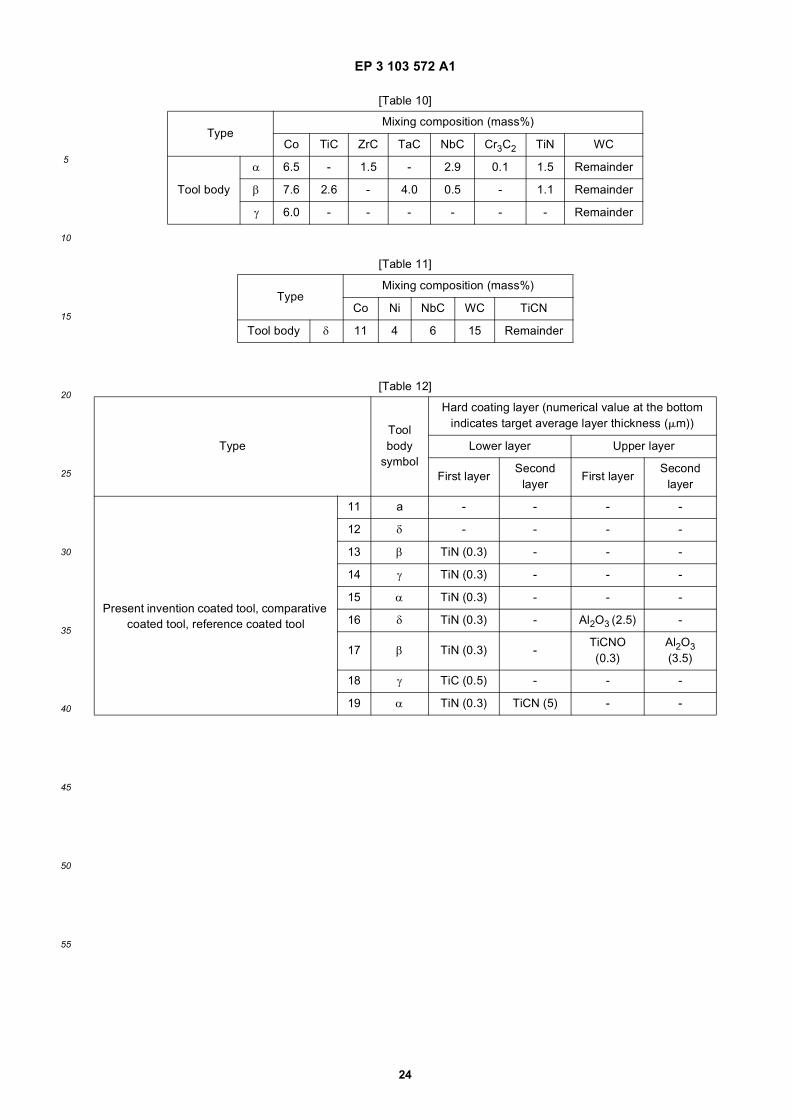
EP 3 103 572 A1
24
5
10
15
20
25
30
35
40
45
50
55
[Table 10]
TypeMixing composition (mass%)
Co TiC ZrC TaC NbC Cr3C2 TiN WC
Tool body
α 6.5 - 1.5 - 2.9 0.1 1.5 Remainder
β 7.6 2.6 - 4.0 0.5 - 1.1 Remainder
γ 6.0 - - - - - - Remainder
[Table 11]
TypeMixing composition (mass%)
Co Ni NbC WC TiCN
Tool body δ 11 4 6 15 Remainder
[Table 12]
TypeTool body
symbol
Hard coating layer (numerical value at the bottom indicates target average layer thickness (mm))
Lower layer Upper layer
First layerSecond
layerFirst layer
Second layer
11 a - - - -
12 δ - - - -
13 β TiN (0.3) - - -
Present invention coated tool, comparative coated tool, reference coated tool
14 γ TiN (0.3) - - -
15 α TiN (0.3) - - -
16 δ TiN (0.3) - Al2O3 (2.5) -
17 β TiN (0.3) -TiCNO (0.3)
Al2O3 (3.5)
18 γ TiC (0.5) - - -
19 α TiN (0.3) TiCN (5) - -

EP 3 103 572 A1
25
5
10
15
20
25
30
35
40
45
50
55
[Tab
le 1
3]
Typ
eT
ool
body
sy
mbo
l
Har
d co
atin
g la
yer
Laye
r of
com
plex
nitr
ide
or c
ompl
ex c
arbo
nitr
ide
of T
i and
Al (
Ti 1
-xA
l x)(
CyN
1-y)
For
ma-
tion
sym
-bo
l of
TiA
lCN
fil
m fo
rm-
ing
proc
-es
s (s
ee
Tab
le 4
)
Ave
r-ag
e am
ount
X
avg
of
Al
Ave
r-ag
e am
ount
Y
avg
of
C
Diff
er-
ence
Dx
betw
een
aver
age
of m
axi-
mum
val
-ue
s of
x
and
an
aver
age
of m
ini-
mum
val
-ue
s
Div
isio
n of
in
clin
ed
angl
es in
w
hich
hi
ghes
t pe
ak is
pr
esen
t in
incl
ined
an
gle
fre-
quen
cy
dist
ribu-
tion
(de-
gree
s)
Pro
port
ion
of fr
eque
n-ci
es o
f 0
degr
ees
to
10 d
e-gr
ees
in in
-cl
ined
an-
gle
divi
sion
in
incl
ined
an
gle
fre-
quen
cy
dist
ribu-
tion
(%)
Ave
r-ag
e gr
ain
wid
th W
of
cub
ic
grai
ns
(mm
)
Ave
r-ag
e as
-pe
ct r
a-tio
A o
f cu
bic
grai
ns
Ave
rage
val
-ue
of p
erio
ds
of c
ompo
si-
tiona
l ch
ange
in T
i an
d A
l alo
ng
<00
1> o
rien-
tatio
n (n
m)
Cha
nge
in
aver
age
amou
nt X
O
of A
l in
plan
e or
thog
onal
to
per
iodi
c co
mpo
si-
tiona
l ch
ange
al
ong
<00
1>
orie
ntat
ion
Latti
ce c
on-
stan
t of
grai
ns h
av-
ing
NaC
l ty
pe fa
ce-
cent
ered
cu-
bic
stru
ctur
e (A
)
Are
a pr
o-po
rtio
n of
he
xago
-na
l fin
e gr
ains
(%
by a
rea)
Ave
rage
gr
ain
size
R
of h
ex-
agon
al
fine
grai
ns
(mm
)
Tar
get
laye
r th
ick-
ness
(m
m)
11α
A0.
900.
0001
or
less
0.14
1.25
-1.5
460.
353.
616
0.01
54.
065
0-
3.5
Pre
sent
in
ven-
tion
coat
ed
tool
12δ
B0.
680.
003
0.19
5.25
-5.5
480.
122.
333
0.01
or
less
4.10
80
-2.
5
13β
C0.
850.
0001
or
less
0.13
1.25
-1.5
722.
23.
848
0.01
or
less
4.07
50
-10
.0
14γ
D0.
860.
0001
or
less
0.09
2.25
-2.5
681.
85
230.
01 o
r le
ss4.
073
0-
7.0
15α
E0.
790.
0012
0.06
1.75
-2.0
781.
67
850.
01 o
r le
ss4.
086
180.
1520
.0
16δ
F0.
710.
0001
or
less
0.13
3.25
-3.5
720.
83.
512
0.01
or
less
4.10
20
-10
.0
17β
G0.
830.
0001
or
less
0.11
3.75
-4.0
661.
16.
565
0.01
or
less
4.07
80
-6.
0
18γ
H0.
770.
0001
or
less
0.05
7.25
-7.5
831.
67
330.
01 o
r le
ss4.
090
250.
119.
0
19α
I0.
840.
0001
or
less
0.09
8.25
-8.5
711.
81.
878
0.01
or
less
4.07
60
-5.
0
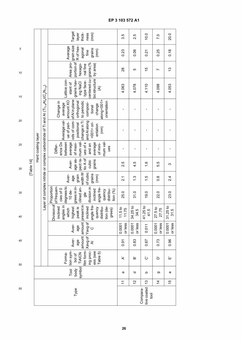
EP 3 103 572 A1
26
5
10
15
20
25
30
35
40
45
50
55
[Tab
le 1
4]
Typ
eT
ool
body
sy
mbo
l
Har
d co
atin
g la
yer
Laye
r of
com
plex
nitr
ide
or c
ompl
ex c
arbo
nitr
ide
of T
i and
Al (
Ti 1
-xA
l x)(
CyN
1-y)
For
ma-
tion
sym
-bo
l of
TiA
lCN
fil
m fo
rm-
ing
proc
-es
s (s
ee
Tab
le 5
)
Ave
r-ag
e am
ount
X
avg
of
Al
Ave
r-ag
e am
ount
Y
avg
of
C
Div
isio
n of
in
clin
ed
angl
es in
w
hich
hi
ghes
t pe
ak is
pr
esen
t in
incl
ined
an
gle
fre-
quen
cy
dist
ribu-
tion
(de-
gree
s)
Pro
port
ion
of fr
eque
n-ci
es o
f 0
degr
ees
to
10 d
e-gr
ees
in in
-cl
ined
an-
gle
divi
sion
in
incl
ined
an
gle
fre-
quen
cy
dist
ribu-
tion
(%)
Ave
r-ag
e gr
ain
wid
th W
of
cub
ic
grai
ns
(mm
)
Ave
r-ag
e as
-pe
ct r
a-tio
A o
f cu
bic
grai
ns
Diff
er-
ence
Dx
betw
een
aver
age
of m
axi-
mum
val
-ue
s of
x
and
an
aver
age
of m
ini-
mum
val
-ue
s
Ave
rage
val
-ue
of p
eri-
ods
of c
om-
posi
tiona
l ch
ange
in T
i an
d A
l alo
ng
<001
> o
ri-en
tatio
n (n
m)
Cha
nge
in
aver
age
amou
nt X
O
of A
l in
plan
e or
thog
onal
to
per
iodi
c co
mpo
si-
tiona
l ch
ange
al
ong
<00
1>
orie
ntat
ion
Latti
ce c
on-
stan
t of
grai
ns h
av-
ing
NaC
l ty
pe fa
ce-
cent
ered
cu-
bic
stru
ctur
e (A
)
Are
a pr
o-po
rtio
n of
he
xago
-na
l fin
e gr
ains
(%
by a
rea)
Ave
rage
gr
ain
size
R
of h
ex-
agon
al
fine
grai
ns
(mm
)
Tar
get
laye
r th
ick-
ness
(m
m)
Com
para
-tiv
e co
ated
to
ol
11a
A’
0.91
0.00
01
or le
ss11
.5 to
11
.75
25.0
2.1
2.5
--
-4.
063
280.
233.
5
12d
B’
0.83
0.00
01
or le
ss34
.25
to
34.5
31.0
1.3
4.5
--
-4.
078
50.
062.
5
13b
C’
0.67
0.01
141
.25
to
41.5
19.0
1.5
1.6
--
-4.
110
150.
2110
.0
14g
D’
0.73
0.00
01
or le
ss27
.5 to
27
.75
22.0
0.8
5.5
--
-4.
098
70.
257.
0
15a
E’
0.96
0.00
01
or le
ss31
.25
to
31.5
23.0
2.4
3-
--
4.05
313
0.18
20.0

EP 3 103 572 A1
27
5
10
15
20
25
30
35
40
45
50
55
(con
tinue
d)
Typ
eT
ool
body
sy
mbo
l
Har
d co
atin
g la
yer
Laye
r of
com
plex
nitr
ide
or c
ompl
ex c
arbo
nitr
ide
of T
i and
Al (
Ti 1
-xA
l x)(
CyN
1-y)
For
ma-
tion
sym
-bo
l of
TiA
lCN
fil
m fo
rm-
ing
proc
-es
s (s
ee
Tab
le 5
)
Ave
r-ag
e am
ount
X
avg
of
Al
Ave
r-ag
e am
ount
Y
avg
of
C
Div
isio
n of
in
clin
ed
angl
es in
w
hich
hi
ghes
t pe
ak is
pr
esen
t in
incl
ined
an
gle
fre-
quen
cy
dist
ribu-
tion
(de-
gree
s)
Pro
port
ion
of fr
eque
n-ci
es o
f 0
degr
ees
to
10 d
e-gr
ees
in in
-cl
ined
an-
gle
divi
sion
in
incl
ined
an
gle
fre-
quen
cy
dist
ribu-
tion
(%)
Ave
r-ag
e gr
ain
wid
th W
of
cub
ic
grai
ns
(mm
)
Ave
r-ag
e as
-pe
ct r
a-tio
A o
f cu
bic
grai
ns
Diff
er-
ence
Dx
betw
een
aver
age
of m
axi-
mum
val
-ue
s of
x
and
an
aver
age
of m
ini-
mum
val
-ue
s
Ave
rage
val
-ue
of p
eri-
ods
of c
om-
posi
tiona
l ch
ange
in T
i an
d A
l alo
ng
<001
> o
ri-en
tatio
n (n
m)
Cha
nge
in
aver
age
amou
nt X
O
of A
l in
plan
e or
thog
onal
to
per
iodi
c co
mpo
si-
tiona
l ch
ange
al
ong
<00
1>
orie
ntat
ion
Latti
ce c
on-
stan
t of
grai
ns h
av-
ing
NaC
l ty
pe fa
ce-
cent
ered
cu-
bic
stru
ctur
e (A
)
Are
a pr
o-po
rtio
n of
he
xago
-na
l fin
e gr
ains
(%
by a
rea)
Ave
rage
gr
ain
size
R
of h
ex-
agon
al
fine
grai
ns
(mm
)
Tar
get
laye
r th
ick-
ness
(m
m)
16d
F’
0.88
0.00
536
.25
to
36.5
31.0
1.5
1.5
--
-4.
069
250.
3410
.0
17b
G’
0.62
0.00
01
or le
ss23
.5 to
23
.75
18.0
1.2
3.2
--
-4.
120
120.
156.
0
18g
H’
0.78
0.00
01
or le
ss17
.5 to
17
.75
26.0
1.3
4.4
--
-4.
088
340.
269.
0
19a
I’0.
80.
003
39.2
5 to
39
.522
.51.
62.
3-
--
4.08
416
0.18
5.0
Ref
eren
ce
coat
ed to
ol20
bA
IP0.
48-
--
1.2
3.5
--
-4.
147
--
3.5
(Not
e) "
AIP
" in
dica
tes
film
form
atio
n th
roug
h ar
c io
n pl
atin
g.

EP 3 103 572 A1
28
5
10
15
20
25
30
35
40
45
50
55
[0073] Next, in a state in which each of the various coated tools was screwed to a tip end portion of an insert holdermade of tool steel by a fixing tool, the present invention coated tools 11 to 19, the comparative coated tools 11 to 19,and the reference coated tool 20 were subjected to a dry high-speed intermittent cutting test for carbon steel and a wethigh-speed intermittent cutting test for cast iron, which are described below, and the flank wear width of a cutting edgewas measured.
Cutting conditions 1:
Work material: a round bar with four longitudinal grooves formed at equal intervals in the longitudinal directionof JIS SCM435Cutting speed: 380 m/minDepth of cut: 1.5 mmFeed rate: 0.2 mm/revCutting time: 5 minutes
(a typical cutting speed is 220 m/min)Cutting conditions 2:
Work material: a round bar with four longitudinal grooves formed at equal intervals in the longitudinal directionof JIS FCD700Cutting speed: 320 m/minDepth of cut: 1.0 mmFeed rate: 0.2 mm/revCutting time: 5 minutes
(a typical cutting speed is 180 m/min)
[0074] The results of the cutting test are shown in Table 15.
Example 3
[0075] As raw material powders, a cBN powder, a TiN powder, a TiCN powder, a TiC powder, an Al powder, and anAl2O3 powder, all of which had an average grain size of 0.5 mm to 4 mm, were prepared, and the raw material powders
[Table 15]
Type
Flank wear width (mm)
Type
Cutting test result (min)
Cutting conditions 1
Cutting conditions 2
Cutting conditions 1
Cutting conditions 2
11 0.26 0.28 11 2.3 3.5
12 0.25 0.31 12 3.6 3.2
Present invention
coated tool
13 0.19 0.21
Comparative coated tool
13 2.1 3.6
14 0.12 0.13 14 4.2 3.3
15 0.15 0.17 15 4.8 2.1
16 0.18 0.16 16 3.6 2.3
17 0.11 0.14 17 1.8 2.5
18 0.22 0.24 18 1.9 2.8
19 0.23 0.21 19 2.3 2.1
Reference coated tool
20 1.2 1.5
Mark * in boxes of comparative coated tools and reference coated tools indicates a cutting time (min) until the endof a service life caused by the occurrence of chipping.

EP 3 103 572 A1
29
5
10
15
20
25
30
35
40
45
50
55
were mixed in mixing compositions shown in Table 16. The mixture was wet-blended by a ball mill for 80 hours and wasdried. Thereafter, the resultant was press-formed into compacts having dimensions with a diameter of 50 mm and athickness of 1.5 mm at a pressure of 120 MPa, and the compacts were then sintered in a vacuum at a pressure of 1 Paunder the condition that the compacts were held at a predetermined temperature in a range of 900°C to 1300°C for 60minutes, thereby producing cutting edge preliminary sintered bodies. In a state in which the preliminary sintered bodywas superimposed on a support piece made of WC-based cemented carbide, which was additionally prepared to containCo: 8 mass% and WC: the remainder and have dimensions with a diameter of 50 mm and a thickness of 2 mm, theresultant was loaded in a typical ultrahigh-pressure sintering apparatus, and was subjected to ultrahigh-pressure sinteringunder typical conditions including a pressure of 4 GPa, a predetermined temperature in a range of 1200°C to 1400°C,and a holding time of 0.8 hours. After the sintering, upper and lower surfaces were polished using a diamond grindingwheel, and were split into predetermined dimensions by a wire electric discharge machining apparatus. Furthermore,the resultant was brazed to a brazing portion (corner portion) of an insert body made of WC-based cemented carbidehaving a composition including Co: 5 mass%, TaC: 5 mass%, and WC: the remainder and a shape (a 80° rhombic shapewith a thickness of 4.76 mm and an inscribed circle diameter of 12.7 mm) according to ISO standard CNGA120412using a brazing filler metal made of a Ti-Zr-Cu alloy having a composition including Zr: 37.5%, Cu: 25%, and Ti: theremainder in terms of mass%, and the outer circumference thereof was machined into predetermined dimensions.Thereafter, a cutting edge portion was subjected to honing to have a width of 0.13 mm and an angle of 25°, and theresultant was further subjected to finish polishing, thereby producing each of tool bodies a and b with an insert shapeaccording to ISO standard CNGA120412.
[0076] Subsequently, present invention coated tools 21 to 24 shown in Table 18 were produced by depositing hardcoating layers including at least a (Ti1-xAlx) (CyN1-y) layer on the surfaces of the tool bodies a and b to have target layerthicknesses using a typical chemical vapor deposition apparatus under the conditions shown in Tables 3 and 4 in thesame method as that in Example 1.[0077] In addition, any of a lower layer and an upper layer shown in Table 17 was formed on the present inventioncoated tools 22 to 24 under the forming conditions shown in Table 3.[0078] In addition, for the purpose of comparison, comparative coated tools 21 to 24 shown in Table 19 were producedby depositing hard coating layers including at least a (Ti1-xAlx) (CyN1-y) layer on the surfaces of the same tool bodies aand b to have target layer thicknesses under the conditions shown in Tables 3 and 5 using a typical chemical vapordeposition apparatus. In addition, like the present invention coated tools 22 to 24, any of a lower layer and an upperlayer shown in Table 17 was formed on the comparative coated tools 22 to 24 under the forming conditions shown inTable 3.[0079] For reference, a reference coated tool 25 shown in Table 19 was produced by depositing (Ti1-xAlx) (CyN1-y)layers on the surfaces of the tool bodies a and b to have target layer thicknesses through arc ion plating using a physicalvapor deposition apparatus in the related art.[0080] The same conditions as those described in Example 1 were used as the conditions of the arc ion plating, andthe reference coated tool 25 was produced by depositing (Al,Ti)N layers having a target composition and a target layerthickness shown in Table 19 on the surfaces of the tool bodies.[0081] The section of each of constituent layers of the present invention coated tools 21 to 24, the comparative coatedtools 21 to 24, and the reference coated tool 25 was measured using a scanning electron microscope (at a magnificationof 5000x). An average layer thickness was obtained by measuring and averaging the layer thicknesses of five points inan observation visual field. All of the results showed substantially the same average layer thicknesses as the target layerthicknesses shown in Tables 17 to 19.[0082] Regarding the hard coating layers of the present invention coated tools 21 to 24, the comparative coated tools21 to 24, and the reference coated tool 25, using the same method as that described in Example 1, the average amountXavg of Al, the average amount Yavg of C, the average grain width W and the average aspect ratio A of crystal grainshaving an NaCl type face-centered cubic structure included in the (Ti1-xAlx) (CyN1-y) layer were calculated. In addition,using the same method as that described in Example 1, inclined angles of normal lines of {111} planes which werecrystal planes of the crystal grains having an NaCl type face-centered cubic structure with respect to the normal line
[Table 16]
TypeMixing composition (mass%)
TiN TiC Al Al2O3 cBN
Tool bodya 50 - 5 3 Remainder
b - 50 4 3 Remainder
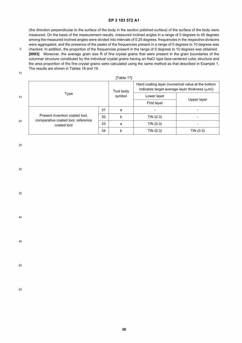
EP 3 103 572 A1
30
5
10
15
20
25
30
35
40
45
50
55
(the direction perpendicular to the surface of the body in the section polished surface) of the surface of the body weremeasured. On the basis of the measurement results, measured inclined angles in a range of 0 degrees to 45 degreesamong the measured inclined angles were divided into intervals of 0.25 degrees, frequencies in the respective divisionswere aggregated, and the presence of the peaks of the frequencies present in a range of 0 degrees to 10 degrees waschecked. In addition, the proportion of the frequencies present in the range of 0 degrees to 10 degrees was obtained.[0083] Moreover, the average grain size R of fine crystal grains that were present in the grain boundaries of thecolumnar structure constituted by the individual crystal grains having an NaCl type face-centered cubic structure andthe area proportion of the fine crystal grains were calculated using the same method as that described in Example 1.The results are shown in Tables 18 and 19.
[Table 17]
TypeTool body
symbol
Hard coating layer (numerical value at the bottom indicates target average layer thickness (mm))
Lower layerUpper layer
First layer
Present invention coated tool, comparative coated tool, reference
coated tool
31 a - -
32 b TiN (0.3) -
33 a TiN (0.3) -
34 b TiN (0.3) TiN (0.3)

EP 3 103 572 A1
31
5
10
15
20
25
30
35
40
45
50
55
[Tab
le 1
8]
Typ
eT
ool
body
sy
mbo
l
Har
d co
atin
g la
yer
Laye
r of
com
plex
nitr
ide
or c
ompl
ex c
arbo
nitr
ide
of T
i and
Al (
Ti 1
-xA
l x)(
CyN
1-y)
For
ma-
tion
sym
-bo
l of
TiA
lCN
fil
m fo
rm-
ing
proc
-es
s (s
ee
Tab
le 4
)
Ave
r-ag
e am
ount
X
avg
of
Al
Ave
r-ag
e am
ount
Y
avg
of
C
Diff
er-
ence
Dx
betw
een
aver
age
of m
axi-
mum
val
-ue
s of
x
and
an
aver
age
of m
ini-
mum
val
-ue
s
Div
isio
n of
in
clin
ed
angl
es in
w
hich
hi
ghes
t pe
ak is
pr
esen
t in
incl
ined
an
gle
fre-
quen
cy
dist
ribu-
tion
(de-
gree
s)
Pro
port
ion
of fr
eque
n-ci
es o
f 0
degr
ees
to
10 d
e-gr
ees
in in
-cl
ined
an-
gle
divi
sion
in
incl
ined
an
gle
fre-
quen
cy
dist
ribu-
tion
(%)
Ave
r-ag
e gr
ain
wid
th W
of
cub
ic
grai
ns
(mm
)
Ave
r-ag
e as
-pe
ct r
a-tio
A o
f cu
bic
grai
ns
Ave
rage
val
-ue
of p
erio
ds
of c
ompo
si-
tiona
l ch
ange
in T
i an
d A
l alo
ng
<00
1> o
rien-
tatio
n (n
m)
Cha
nge
in
aver
age
amou
nt X
O
of A
l in
plan
e or
thog
onal
to
per
iodi
c co
mpo
si-
tiona
l ch
ange
al
ong
<00
1>
orie
ntat
ion
Latti
ce c
on-
stan
t of
grai
ns h
av-
ing
NaC
l ty
pe fa
ce-
cent
ered
cu-
bic
stru
ctur
e (Å
)
Are
a pr
o-po
rtio
n of
he
xago
-na
l fin
e gr
ains
(%
by a
rea)
Ave
rage
gr
ain
size
R
of h
ex-
agon
al
fine
grai
ns
(mm
)
Tar
get
laye
r th
ick-
ness
(m
m)
Pre
sent
in
ven-
tion
coat
ed
tool
21a
A0.
910.
0001
or
less
0.15
5.25
to 5
.555
0.4
318
0.01
54.
063
0-
3.5
22b
B0.
660.
002
0.18
7.5
to 7
.75
480.
25
280.
01 o
r le
ss4.
112
0-
1.2
23a
C0.
850.
0001
or
less
0.09
1.25
to 1
.561
0.9
2.1
430.
01 o
r le
ss4.
075
0-
2.0
24b
D0.
810.
0001
or
less
0.11
2.25
to 2
.553
0.8
2.8
260.
01 o
r le
ss4.
082
0-
2.5

EP 3 103 572 A1
32
5
10
15
20
25
30
35
40
45
50
55
[Tab
le 1
9]
Typ
eT
ool
body
sy
mbo
l
Har
d co
atin
g la
yer
Laye
r of
com
plex
nitr
ide
or c
ompl
ex c
arbo
nitr
ide
of T
i and
Al (
Ti 1
-xA
l x)(
CyN
1-y)
For
ma-
tion
sym
-bo
l of
TiA
lCN
fil
m fo
rm-
ing
proc
-es
s (s
ee
Tab
le 5
)
Ave
r-ag
e am
ount
X
avg
of
Al
Ave
r-ag
e am
ount
Y
avg
of
C
Div
isio
n of
in
clin
ed
angl
es in
w
hich
hi
ghes
t pe
ak is
pr
esen
t in
incl
ined
an
gle
fre-
quen
cy
dist
ribu-
tion
(de-
gree
s)
Pro
port
ion
of fr
eque
n-ci
es o
f 0
degr
ees
to
10 d
e-gr
ees
in in
-cl
ined
an-
gle
divi
sion
in
incl
ined
an
gle
fre-
quen
cy
dist
ribu-
tion
(%)
Ave
r-ag
e gr
ain
wid
th W
of
cub
ic
grai
ns
(mm
)
Ave
r-ag
e as
-pe
ct r
a-tio
A o
f cu
bic
grai
ns
Diff
er-
ence
Dx
betw
een
aver
age
of m
axi-
mum
val
-ue
s of
x
and
an
aver
age
of m
ini-
mum
val
-ue
s
Ave
rage
val
-ue
of p
eri-
ods
of c
om-
posi
tiona
l ch
ange
in T
i an
d A
l alo
ng
<001
> o
ri-en
tatio
n (n
m)
Cha
nge
in
aver
age
amou
nt X
O
of A
l in
plan
e or
thog
onal
to
per
iodi
c co
mpo
si-
tiona
l ch
ange
al
ong
<00
1>
orie
ntat
ion
Latti
ce c
on-
stan
t of
grai
ns h
av-
ing
NaC
l ty
pe fa
ce-
cent
ered
cu-
bic
stru
ctur
e (A
)
Are
a pr
o-po
rtio
n of
he
xago
-na
l fin
e gr
ains
(%
by a
rea)
Ave
rage
gr
ain
size
R
of h
ex-
agon
al
fine
grai
ns
(mm
)
Tar
get
laye
r th
ick-
ness
(m
m)
Com
para
-tiv
e co
ated
to
ol
21a
A’
0.93
0.00
01
or le
ss15
.5 to
15
.75
29.0
0.8
2.2
--
-4.
059
230.
253.
5
22b
B’
0.85
0.00
01
or le
ss22
.25
to
22.5
19.0
0.6
2.5
--
-4.
075
30.
121.
2
23a
C’
0.63
0.00
938
.25
to
38.5
23.0
0.7
1.3
--
-4.
118
160.
182.
0
24b
D’
0.71
0.00
01
or le
ss16
to
16.2
527
.00.
92.
4-
--
4.10
25
0.26
2.5
Ref
eren
ce
coat
ed to
ol25
bA
lP0.
48-
--
1.2
3.5
--
-4.
147
--
2.5
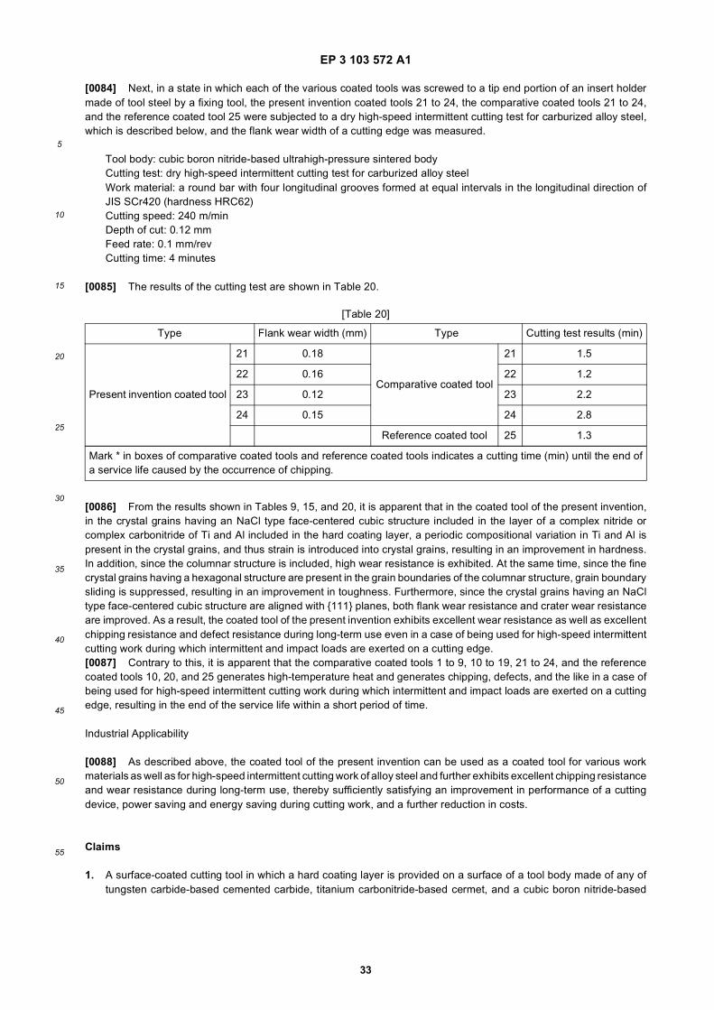
EP 3 103 572 A1
33
5
10
15
20
25
30
35
40
45
50
55
[0084] Next, in a state in which each of the various coated tools was screwed to a tip end portion of an insert holdermade of tool steel by a fixing tool, the present invention coated tools 21 to 24, the comparative coated tools 21 to 24,and the reference coated tool 25 were subjected to a dry high-speed intermittent cutting test for carburized alloy steel,which is described below, and the flank wear width of a cutting edge was measured.
Tool body: cubic boron nitride-based ultrahigh-pressure sintered bodyCutting test: dry high-speed intermittent cutting test for carburized alloy steelWork material: a round bar with four longitudinal grooves formed at equal intervals in the longitudinal direction ofJIS SCr420 (hardness HRC62)Cutting speed: 240 m/minDepth of cut: 0.12 mmFeed rate: 0.1 mm/revCutting time: 4 minutes
[0085] The results of the cutting test are shown in Table 20.
[0086] From the results shown in Tables 9, 15, and 20, it is apparent that in the coated tool of the present invention,in the crystal grains having an NaCl type face-centered cubic structure included in the layer of a complex nitride orcomplex carbonitride of Ti and Al included in the hard coating layer, a periodic compositional variation in Ti and Al ispresent in the crystal grains, and thus strain is introduced into crystal grains, resulting in an improvement in hardness.In addition, since the columnar structure is included, high wear resistance is exhibited. At the same time, since the finecrystal grains having a hexagonal structure are present in the grain boundaries of the columnar structure, grain boundarysliding is suppressed, resulting in an improvement in toughness. Furthermore, since the crystal grains having an NaCltype face-centered cubic structure are aligned with {111} planes, both flank wear resistance and crater wear resistanceare improved. As a result, the coated tool of the present invention exhibits excellent wear resistance as well as excellentchipping resistance and defect resistance during long-term use even in a case of being used for high-speed intermittentcutting work during which intermittent and impact loads are exerted on a cutting edge.[0087] Contrary to this, it is apparent that the comparative coated tools 1 to 9, 10 to 19, 21 to 24, and the referencecoated tools 10, 20, and 25 generates high-temperature heat and generates chipping, defects, and the like in a case ofbeing used for high-speed intermittent cutting work during which intermittent and impact loads are exerted on a cuttingedge, resulting in the end of the service life within a short period of time.
Industrial Applicability
[0088] As described above, the coated tool of the present invention can be used as a coated tool for various workmaterials as well as for high-speed intermittent cutting work of alloy steel and further exhibits excellent chipping resistanceand wear resistance during long-term use, thereby sufficiently satisfying an improvement in performance of a cuttingdevice, power saving and energy saving during cutting work, and a further reduction in costs.
Claims
1. A surface-coated cutting tool in which a hard coating layer is provided on a surface of a tool body made of any oftungsten carbide-based cemented carbide, titanium carbonitride-based cermet, and a cubic boron nitride-based
[Table 20]
Type Flank wear width (mm) Type Cutting test results (min)
Present invention coated tool
21 0.18
Comparative coated tool
21 1.5
22 0.16 22 1.2
23 0.12 23 2.2
24 0.15 24 2.8
Reference coated tool 25 1.3
Mark * in boxes of comparative coated tools and reference coated tools indicates a cutting time (min) until the end ofa service life caused by the occurrence of chipping.

EP 3 103 572 A1
34
5
10
15
20
25
30
35
40
45
50
55
ultrahigh-pressure sintered body, wherein
(a) the hard coating layer includes at least a layer of a complex nitride or complex carbonitride of Ti and Al, thelayer being formed to an average layer thickness of 1 mm to 20 mm in a chemical vapor deposition method, andin a case where the layer is expressed by the composition formula: (Ti1-xAlx) (CyN1-y), an average amount Xavgof Al of the layer of a complex nitride or complex carbonitride in a total amount of Ti and Al and an averageamount Yavg of C in a total amount of C and N (both Xavg and Yavg are atomic ratios) respectively satisfy 0.60≤ Xavg ≤ 0.95 and 0 ≤ Yavg ≤ 0.005,(b) the layer of a complex nitride or complex carbonitride includes at least a phase of a complex nitride orcomplex carbonitride having an NaCl type face-centered cubic structure,(c) regarding the layer of a complex nitride or complex carbonitride, in a case where crystal orientations ofindividual crystal grains having an NaCl type face-centered cubic structure in the layer of a complex nitride orcomplex carbonitride in a longitudinal sectional direction of the layer of a complex nitride or complex carbonitrideare analyzed using an electron backscatter diffraction apparatus, when an inclined angle frequency distributionis obtained by measuring inclined angles of normal lines of {111} planes which are crystal planes of the crystalgrains with respect to a normal direction of the surface of the tool body, dividing inclined angles in a range of 0degrees to 45 degrees with respect to the normal direction among the measured inclined angles into intervalsof 0.25 degrees, and aggregating frequencies in the respective divisions, a highest peak is present in an inclinedangle division in a range of 0 degrees to 10 degrees, and a sum of frequencies that are present in the range of0 degrees to 10 degrees has a proportion of 45% or higher of a total of the frequencies in the inclined anglefrequency distribution,(d) regarding the layer of a complex nitride or complex carbonitride, in a case where the layer is observed inthe longitudinal sectional direction, a columnar structure in which an average grain width W of the individualcrystal grains having an NaCl type face-centered cubic structure in the layer of a complex nitride or complexcarbonitride is 0.1 mm to 2.0 mm and an average aspect ratio A thereof is 2 to 10 is included, and(e) in the individual crystal grains having an NaCl type face-centered cubic structure in the layer of a complexnitride or complex carbonitride, a periodic compositional variation in Ti and Al in the (Ti1-xAlx) (CyN1-y) is presentalong one orientation among equivalent crystal orientations expressed by <001> of the crystal grains, and adifference Δx between an average of maximum values of x which varies periodically and an average of minimumvalues thereof is 0.03 to 0.25.
2. The surface-coated cutting tool according to claim 1,wherein, in the crystal grains having an NaCl type face-centered cubic structure in which the periodic compositionalvariation in Ti and Al is present in the layer of a complex nitride or complex carbonitride, the periodic compositionalvariation in Ti and Al is present along one orientation among the equivalent crystal orientations expressed by <001>of the crystal grains, a period along the orientation is 3 nm to 100 nm, and a change in an amount XO of Al in aplane perpendicular to the orientation in a total amount of Ti and Al is 0.01 or less.
3. The surface-coated cutting tool according to claim 1 or 2,wherein, regarding the layer of a complex nitride or complex carbonitride, lattice constants a of the crystal grainshaving an NaCl type face-centered cubic structure are obtained from X-ray diffraction, and the lattice constants aof the crystal grains having an NaCl type face-centered cubic structure satisfy a relationship of 0.05aTiN + 0.95aAlN≤ a ≤ 0.4aTiN + 0.6 aAlN for a lattice constant aTiN of cubic TiN and a lattice constant aAlN of cubic AlN.
4. The surface-coated cutting tool according to any one of claims 1 to 3,wherein the layer of a complex nitride or complex carbonitride is formed of a single phase of a complex nitride orcomplex carbonitride of Ti and Al having an NaCl type face-centered cubic structure.
5. The surface-coated cutting tool according to any one of claims 1 to 3,wherein, regarding the layer of a complex nitride or complex carbonitride, in a case where the layer is observed inthe longitudinal sectional direction, in grain boundaries of the columnar structure constituted by the individual crystalgrains having an NaCl type face-centered cubic structure in the layer of a complex nitride or complex carbonitride,fine crystal grains having a hexagonal structure are present, an area proportion of the fine crystal grains present is30% or lower by area, and an average grain size R of the fine crystal grains is 0.01 mm to 0.3 mm.
6. The surface-coated cutting tool according to any one of claims 1 to 5,wherein, between the tool body and the layer of a complex nitride or complex carbonitride of Ti and Al, a lower layerwhich is formed of a Ti compound layer that includes one layer or two or more layers of a Ti carbide layer, a Ti nitride

EP 3 103 572 A1
35
5
10
15
20
25
30
35
40
45
50
55
layer, a Ti carbonitride layer, a Ti oxycarbide layer, and a Ti oxycarbonitride layer and has an average total layerthickness of 0.1 mm to 20 mm is present.
7. The surface-coated cutting tool according to any one of claims 1 to 6,wherein an upper layer which includes an aluminum oxide layer having an average layer thickness of at least 1 mmto 25 mm is present in an upper portion of the layer of a complex nitride or complex carbonitride.
8. The surface-coated cutting tool according to any one of claims 1 to 7,wherein the layer of a complex nitride or complex carbonitride is formed by a chemical vapor deposition method inwhich at least trimethylaluminum is contained as a reaction gas component.

EP 3 103 572 A1
36

EP 3 103 572 A1
37
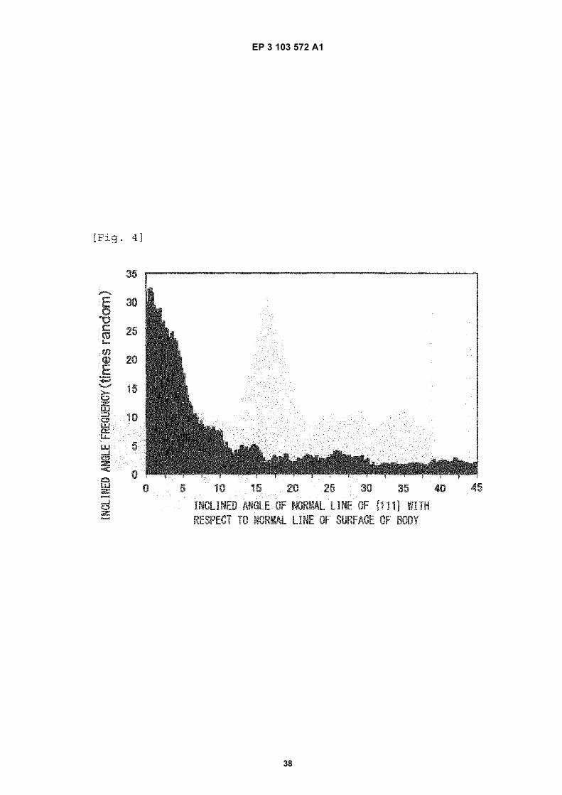
EP 3 103 572 A1
38

EP 3 103 572 A1
39
EP 3 103 572 A1
40
5
10
15
20
25
30
35
40
45
50
55

EP 3 103 572 A1
41
5
10
15
20
25
30
35
40
45
50
55

EP 3 103 572 A1
42
REFERENCES CITED IN THE DESCRIPTION
This list of references cited by the applicant is for the reader’s convenience only. It does not form part of the Europeanpatent document. Even though great care has been taken in compiling the references, errors or omissions cannot beexcluded and the EPO disclaims all liability in this regard.
Patent documents cited in the description
• JP 2000144376 A [0007]• JP 2011516722 T [0007]
• JP 2011513594 T [0007]