18sp628 – mbe4000 oil gallery cup plug – bracket and epoxy
TRANSCRIPT

18SP628 – MBE4000 Oil Gallery Cup Plug – Bracket and Epoxy Installation KIT DESCRIPTION A new service kit (P/N: 23536001) is now available to install a bracket with epoxy to retain and seal two rear oil gallery cup plugs on the MBE4000 engine. The kit contains enough parts for four engines.
NOTICE: • This kit should only be used on unit serial number range 0460817468
through 0460840294. • If there is oil leaking from either of the two rear cup plugs, do NOT install this kit. Call
the Detroit Diesel Customer Support Center at 313-592-5800 for further instructions. • If the plugs are a threaded design, do NOT install this kit. See the picture below.
The threaded plugs protrude out of the cylinder block.
KIT CONTENTS This kit contains the following parts listed in Table 1.
Part Number Quantity Description 23536473 4 Bracket
23536474 4 Stiffening bracket
11503804 4 Bolt M6 x 16
23511786 4 Bolt M10 x 25
23536475 1 Epoxy
98455 1 Epoxy Installation Nozzles (Pack of 10)
18SP628 1 Instruction Sheet Table 1 Content for Service Kit (P/N: 23536001)
18SP628 Page 1 of 6
INSTALLATION PROCEDURE Install the bracket as follows:
1. Apply the parking brake, chock the wheels, and perform any other applicable safety steps.
2. Remove the passenger side inner wheel well and turn the wheels all the way to the left to improve access to the engine.
3. Disconnect vehicle battery power.
4. Remove the starter.
5. Clean and dry the area around the cup plugs so it is free from dirt, debris, oil, etc.
6. Slide the bracket from the kit in from the bottom of the vehicle. See Figure 1.
Figure 1 Inserting the Bracket from Bottom of Vehicle
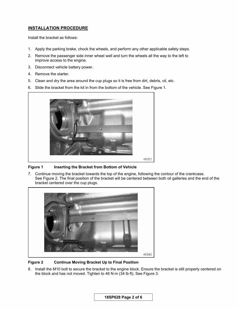
7. Continue moving the bracket towards the top of the engine, following the contour of the crankcase. See Figure 2. The final position of the bracket will be centered between both oil galleries and the end of the bracket centered over the cup plugs.
Figure 2 Continue Moving Bracket Up to Final Position
8. Install the M10 bolt to secure the bracket to the engine block. Ensure the bracket is still properly centered on the block and has not moved. Tighten to 46 N·m (34 lb·ft). See Figure 3.
18SP628 Page 2 of 6
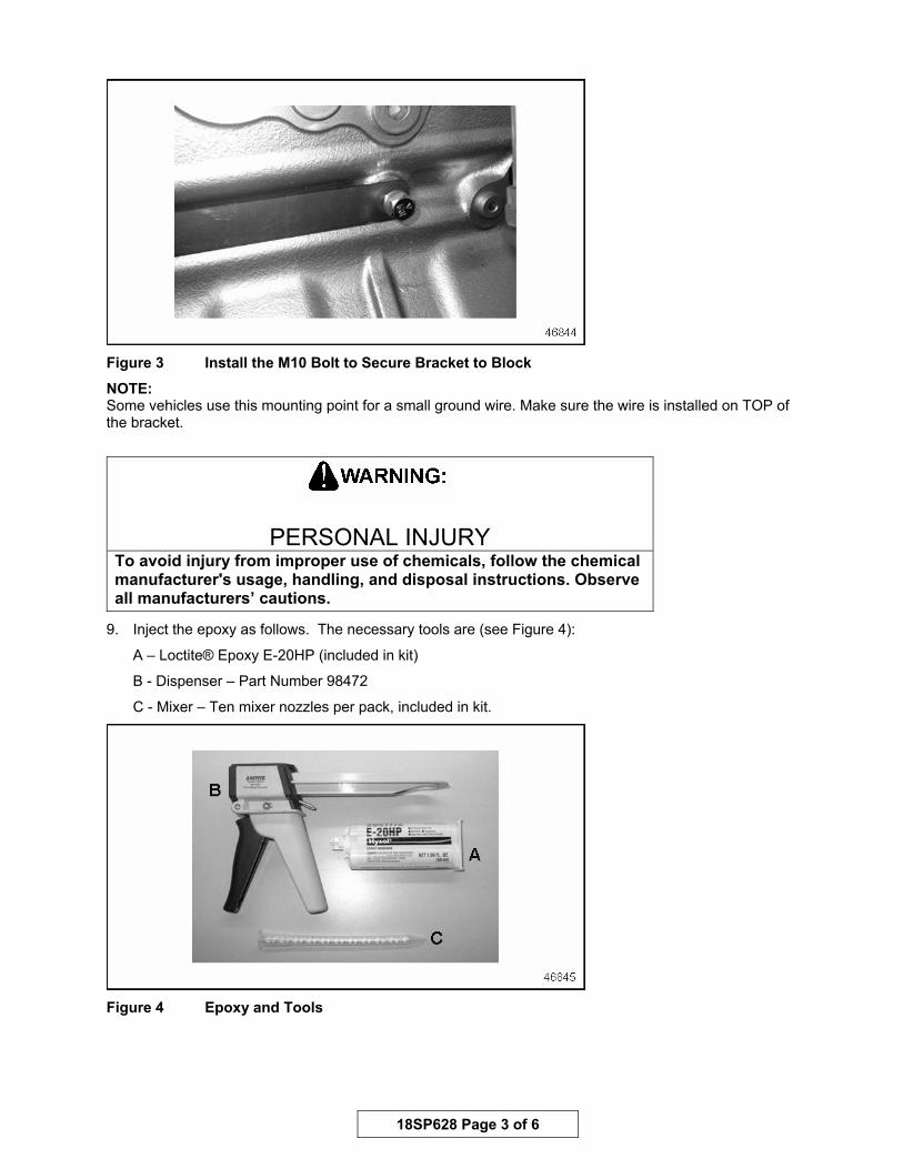
Figure 3 Install the M10 Bolt to Secure Bracket to Block
NOTE: Some vehicles use this mounting point for a small ground wire. Make sure the wire is installed on TOP of the bracket.
PERSONAL INJURY To avoid injury from improper use of chemicals, follow the chemical manufacturer's usage, handling, and disposal instructions. Observe all manufacturers’ cautions.
9. Inject the epoxy as follows. The necessary tools are (see Figure 4):
A – Loctite® Epoxy E-20HP (included in kit)
B - Dispenser – Part Number 98472
C - Mixer – Ten mixer nozzles per pack, included in kit.
Figure 4 Epoxy and Tools
18SP628 Page 3 of 6

10. Install the dispenser ram into the trigger gun. Two rams come with the trigger gun: one with a 2:1 mixture ratio and one with a 1:1 mixture ratio. Use the 2:1 mixture ratio ram. See Figure 5.
Figure 5 Mixture Ratio listed on Trigger Gun Ram
11. Install the epoxy cartridge into the dispenser.
12. Remove the cap from the cartridge and install mixing nozzle.
13. Fill the channels in the bracket. See Figure 6 for a close-up view of the channels in the bracket.
Figure 6 Fill Channels in Bracket with Epoxy
14. Fill the upper channel in the bracket slowly until a steady stream of epoxy comes back out of the channel. See Figure 7.
18SP628 Page 4 of 6
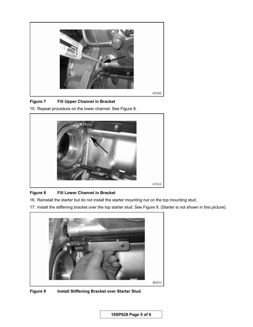
Figure 7 Fill Upper Channel in Bracket
15. Repeat procedure on the lower channel. See Figure 8.
Figure 8 Fill Lower Channel in Bracket
16. Reinstall the starter but do not install the starter mounting nut on the top mounting stud.
17. Install the stiffening bracket over the top starter stud. See Figure 9. (Starter is not shown in this picture).
Figure 9 Install Stiffening Bracket over Starter Stud
18SP628 Page 5 of 6

18. Loosely install the M6 bolt from the stiffening bracket to the main bracket.
19. Install and tighten the top starter nut.
20. Tighten the M6 bolt to 9 N·m (7 lb·ft). See Figure 10. (Starter is not shown in this picture).
Figure 10 Tighten M6 Bolt on Bracket
21. Reinstall any other removed components.
22. Do NOT start the engine until the epoxy has fully cured and hardened. (See Notice).
23. After allowing the epoxy to cure, start and run the engine and check for oil leaks.
NOTICE: • The cure time for the epoxy is 90-120 minutes at 75° F (23° C). Curing time will
increase in colder weather.
• Heating the surrounding area will speed up the curing process, decreasing the curing time. DO NOT APPLY DIRECT HEAT TO EPOXY.
Copyright© 2005 Detroit Diesel Corporation. Detroit Diesel®, DDC®, and the spinning arrows design are registered trademarks of Detroit Diesel Corporation. Loctite® is a registered trademark of Loctite Corporation. All other trademarks are the property of their respective owners. 18SP628 0512 As technical advances continue, specifications will change. All rights reserved. Printed in U.S.A.
18SP628 Page 6 of 6