18/28/38p series - lsr distribuidor filtracion parte 2.pdf · 0 50 100 150 200 250 300 0 10 20 30...
TRANSCRIPT

18/28/38P SeriesHigh Pressure Filters
125

High Pressure Filters 18/28/38P Series
Parker Hannifin CorporationHydraulic Filter DivisionMetamora, OH
Applications for 18/28/38P series■ Injection Molding
■ Die Casting
■ Servo Controls
■ Machine Tools
■ Mobile Equipment
Parker Filtration’s Hydraulic Filter Division engineered the 18/28/38P series of high pressure filters to satisfy demanding applications in the mobile and industrial markets throughout the world. With metric mounting and optional ISO 6149 ports, this new series is truly a global design.
Installed downstream of the pump, this new series with their wide range of high capacity Microglass III elements, offer excellent protection to system components.
Standard filters come complete with industry proven spool type bypass valve. For more critical applications such as servo or proportional controls, a no bypass high strength element combination ensures maximum protection.
The modular low hysteresis differential pressure indicator fitted to this series is unrivaled in its performance. Tests prove it’s accuracy and foolproof design to be a major advance in indicator technology.
126

High Pressure Filters 18/28/38P Series
Parker Hannifin CorporationHydraulic Filter DivisionMetamora, OH127
Ports ■ SAE, ISO 6149 or flange face ports provide maximum mounting flexibility.
Element Assembly ■High efficiency (Bx > 200),
high capacity Microglass III media with it’s multilayered
design is unequalled in performance.
■ IndicatorAvailable as a visual (auto reset) or electrical with choice of several power connections.
■ HeadSG iron material is used to provide high fatigue strength (6000 psi).
■ BypassHigh precision spool type valve, “no bypass” option available for critical applications.
■ BowlSteel bowl provides high strength with precision finish for sealing surfaces. Bowl down design allows for draining prior to element servicing.
Features
Bowl Seal ■ Diametral head to bowl
seal with anti-extrusion ring is reliable for high
cyclic applications.

High Pressure Filters 18/28/38P Series
Parker Hannifin CorporationHydraulic Filter DivisionMetamora, OH
18P Element Performance
128
Efficiency %Efficiency
Beta Rating
1000
10000
99.9
99.599.0100
200
20
2 50.0
95.0
Micron Size (c)
2Q
10Q
20Q
5Q
0 4 8 12 16 20
PSID
50
40
30
20
10
0
GPM
02QH
20QH
05QH
BAR
LPM
3.0
2.0
2.0
1.5
1.0
0.5
0.0
10QH
18P-2 High CollapseElement Only150 SUS
0 20 40 60 80
0 5 10 15 20 25
ModEl
Media 18P-1 18P-1 18P-2 18P-2Code (50 psid) (98 psid) (50 psid) (98 psid)
02Q 5.9 7.4 18.6 22.705Q 8.5 9.4 21.0 23.510Q 7.6 8.0 15.8 17.220Q 7.7 8.6 16.2 17.702QH 4.8 6.3 14.1 17.805QH 7.5 8.8 17.1 19.610QH 6.7 7.2 14.5 16.120QH 6.6 7.2 11.9 12.6
Capacity (grams)PS
ID
50
40
30
20
10
0
GPM
02Q
20Q
05Q
BAR
LPM
3.0
2.5
2.0
1.5
1.0
0.5
0.0
10Q
18P-1 Element Only150 SUS
0 5 10 15 20 25
0 20 40 60 80
02QH
PSID
50
40
30
20
10
0
GPM
20QH05QH
BA
R
LPM
3.0
2.5
2.0
1.5
1.0
0.5
0.0
10QH
18P-1 High CollapseElement Only
Empty Housing
150 SUS
0 5 10 15 20 25
0 20 40 60 80
PSID
50
40
30
20
10
0
GPM
02Q
20Q
05Q
BAR
LPM
3.0
2.5
2.0
1.5
1.0
0.5
0.0
10Q
18P-2 Element Only150 SUS
0 20 40 60 80
0 5 10 15 20 25
Flow vs. Pressure loss

High Pressure Filters 18/28/38P Series
Parker Hannifin CorporationHydraulic Filter DivisionMetamora, OH
Efficiency %Efficiency
Beta Rating
1000
10000
99.9
99.599.0100
200
20
2 50.0
95.0
Micron Size (c)
2Q
10Q
20Q
5Q
0 4 8 12 16 20
129
28P Element PerformancePS
ID
50
40
30
20
10
0
GPM
02QH
20QH
050QH
BAR
LPM
3.0
2.5
2.0
1.5
1.0
0.5
0.0
10QH
28P-1 High Collapse Element Only
Empty Housing
150 SUS
0 10 20 30 40 50 60 70 80
0 50 100 150 200 250 300
PSID
50
40
30
20
10
0
GPM
02Q
20Q
05Q
BAR
LPM
3.0
2.5
2.0
1.5
1.0
0.5
0.0
10Q
28P-1 Element Only150 SUS
0 50 100 150 200 250 300
0 10 20 30 40 50 60 70 80
PSID
50
40
30
20
10
0
GPM
02QH
20QH
05QH
BAR
LPM
3.0
2.5
2.0
1.5
1.0
0.5
0.0
10QH
28P-2 High Collapse Element Only
150 SUS
0 50 100 150 200 250 300
0 10 20 30 40 50 60 70 80
PSID
50
40
30
20
10
0
GPM
02Q
20Q
05Q
BAR
LPM
3.0
2.5
2.0
1.5
1.0
0.5
0.0
10Q
28P-2 Element Only150 SUS
0 50 100 150 200 250 300
0 10 20 30 40 50 60 70 80
ModEl
Media 28P-1 28P-1 28P-2 28P-2Code (50 psid) (98 psid) (50 psid) (98 psid)
02Q 23 28 40 48 05Q 25 28 43 50 10Q 22 24 45 48 20Q 21 24 44 48 02QH 21 24 32 38 05QH 24 27 35 38 10QH 21 23 35 38 20QH 20 22 34 37
Capacity (grams)
Flow vs. Pressure loss

High Pressure Filters 18/28/38P Series
Parker Hannifin CorporationHydraulic Filter DivisionMetamora, OH
38P Element Performance
130
Efficiency %Efficiency
Beta Rating
1000
10000
99.9
99.599.0100
200
20
2 50.0
95.0
Micron Size (c)
2Q
10Q
20Q
5Q
0 4 8 12 16 20
PSI
D
50
40
30
20
10
0
GPM
BA
R
LPM
3.0
2.5
2.0
1.5
1.0
0.5
0.0
38P-1 High Collapse Element Only
02Q H
20Q H
05Q H
10Q H
Empty Housing
150 SUS
0 30 60 90 120 150
0 100 200 300 400 500
PSID
50
40
30
20
10
0
GPM
02Q
20Q
05Q
BAR
LPM
3.0
2.5
2.0
1.5
1.0
0.5
0.0
10Q
38P-1 Element Only150 SUS
0 100 200 300 400 500
0 30 60 90 120 150
PSID
50
40
30
20
10
0
GPM
BAR
LPM
3.0
2.5
2.0
1.5
1.0
0.5
0.0
38P-2 High Collapse Element Only
02QH
20QH
05QH
10QH
150 SUS
0 100 200 300 400 500
0 30 60 90 120 150
PSID
50
40
30
20
10
0
GPM
02Q
20Q
05Q
BAR
LPM
3.0
2.5
2.0
1.5
1.0
0.5
0.0
10Q
38P-2 Element Only150 SUS
0 30 60 90 120 150
0 100 200 300 400 500
ModEl
Media 38P-1 38P-1 38P-2 38P-2Code (50 psid) (98 psid) (50 psid) (98 psid)
02Q 63 74 94 11105Q 70 78 98 10510Q 60 67 94 10120Q 53 60 93 10002QH 48 57 69 87 05QH 55 61 76 88 10QH 50 56 72 80 20QH 49 54 72 78
Capacity (grams)
Flow vs. Pressure loss

High Pressure Filters 18/28/38P Series
Parker Hannifin CorporationHydraulic Filter DivisionMetamora, OH
3.93 (100)
D E
C
I
HM
GL K
J
Torque60 -70 ft/lbs.
Bo wl Rem oval
Hex.35.3836.0 A/F
4 Mounting holesM10 x 1.5 pitchx 12 deep
Single LengthA
Double LengthB
R48
Specifications: 18/28/38P SeriesPressure Ratings:Maximum Allowable Operating Pressure(MAOP): 6000 psi (413.8 bar)Rated Fatigue Pressure: 6000 psi (413.8 bar)Design Safety Factor: 3:1
operating Temperatures:-30oF (-34oC) to 250oF (120oC)
Element Collapse Rating: Standard: 300 psi (20.7 bar)High Collapse “H” option: 3000 psi (206.9 bar)
Materials:Head: SG IronBowl: steelIndicator: stainless steel body, plastic connectors
Weights (approximate):Model Single length Double length18P 9.3 lbs. (4.2 kg) 12.6 lbs. (4.2 kg)28P 14.8 lbs. (6.7 kg) 20.3 lbs. (9.2 kg)38P 34.8 lbs. (15.8 kg) 44.8 lbs. (20.3 kg)
131
E
C
Single LengthA
Double LengthB
3.93 (100)
M
H
I
G
LK
J
D
Torque15-20 ft/lbs.
Bo wl Rem ova l
Hex. 23.324.0 A/F
4 Mounting holesM8 x 1.25-6H pitch
x 12 deep
3.93 (100)
ED
C
H
M
I
G
LK
J
Torque25-30 ft/lbs.
Bo wl Rem oval
Hex. 23.324.0 A/F
4 Mounting holesM10 x 1.5 pitchx 11 deep
Single LengthA
Double LengthB
A B C D E G H I J K L M
7.79 (198) 11.53 (293) 2.95 (75) 1.26 (32) 102 (26) 3.15 (80) 1.57 (40) 3.86 (98) 4.33 (110) 2.17 (55) 1.57 (40) .78 (20)
9.29 (236) 13.58 (345) 3.66 (93) 1.57 (40) 1.14 (29) 3.54 (90) 2.17 (55) 4.72 (120) 4.88 (124) 2.44 (62) 1.77 (45) 1.08 (27.5)
12.76 (324) 17.44 (443) 5.04 (128) 1.73 (44) 1.37 (35) 4.72 (120) 1.97 (50) 6.30 (160) 6.38 (162) 3.19 (81) 2.36 (60) .98 (25)
Dimensions are in(mm)
18P28P38P
18P 28P 38P

High Pressure Filters 18/28/38P Series
Parker Hannifin CorporationHydraulic Filter DivisionMetamora, OH132
Specifications: 18P/28P/38PElement Condition Indicators:
option description Connection/Power Wiring “A” “B”
M2 Visual Auto Reset N/A N/A N/A 1.44 (36.6)
E2 Electrical - Visual Din 43650 3 Pole + Earth Pin 1 - Common 5A@125/250 VAC, 3A@28VDC Pin 2 - Normally Closed 2.90 (73.7) 1.44 (36.6) Pin 3 - Normally Open
E3 Electrical - Visual 3 Pin ANSI/B93.55M Pin 1 - Common 5A@125/250 VAC, 3A@28VDC Pin 2 - Normally Closed 2.32 (58.8) 1.44 (36.6) Pin 3 - Normally Open
H Electrical - Heavy Duty ½” Conduit adapter w/24” leads Black - Normally Open .25A (resistive) Max 5 Watts Blue - Normally Closed N/A 3.31 (84.1) 12 to 28 VDC & 110 to 175 VAC White - Common
H1 Electrical - Heavy Duty 24” wire leads Black - Normally Open .25A (resistive) Max 5 Watts Blue - Normally Closed N/A 2.58 (65.5) 12 to 28 VDC & 110 to 175 VAC White - Common
A B C D E F G
.47 (11.9) .94 (23.8) 1.00 (25.4) 2.00 (50.8) M10 x 1.5-6H x 18 DP 3/8-16 UNC-2B x 18 DP .75 (19.0)
.54 (13.9) 1.09 (27.8) 1.10 (28.0) 2.25 (57.1) M10 x 1.75-6H x 20 DP 7/16-14 UNC-2B x 20 DP 1.00 (25.4)
.62 (15.7) 1.25 (31.7) 1.30 (33.0) 2.63 (66.7) M14 x 2-6H x 20 DP 1/2-13 UNC-2B x 20 DP 1.25 (31.8)
Dimensions are in(mm)
18P28P38P
Thread E metricF SAE
BA
ø G
C
D M.A.O.P flange 6000 psi (414 bar)
Flange Face details
B
E2A
2
1
3
B
E3A
1
32
B
H
B
H1
B
M2

High Pressure Filters 18/28/38P Series
Parker Hannifin CorporationHydraulic Filter DivisionMetamora, OH
6
5
7
4
1
8
9
3
2
Element ServiceA. Stop the system’s power unit.B. Relieve any system pressure
in the filter line.C. Drain the filter bowl if
necessary.D. Loosen and remove bowl.E. Remove element by pulling
downward with a slight twisting motion and discard.
F. Discard used spiral back-up ring (white) and o-ring from filter bowl.
G. Install new solid back-up ring (black). The top/bottom orientation is non-critical.
H. Ensure the back-up ring is not twisted.
I. Replace the bowl o-ring.J. Lubricate element o-ring
with system fluid and place element on post in filter head.
K. Lubricate bowl o-ring, install bowl and tighten to specified torque.
18P - 15-20 ft. lbs. 28P - 25-30 ft. lbs. 38P - 60-70 ft. lbsL. Confirm there are no leaks
after powering the system.
133
Parts list Index description 18P 28P 38P
1 Head Assembly Consult Factory 2 Element (See model code page) 3 Bowl Single length w/o drain S04429 S04437 S04445 Double length w/o drain S04430 S04438 S04446* Not Shown Drain Plug (SAE-5) — — 927363 Not Shown Drain Plug O-Ring Nitrile — — N93905 Fluorocarbon — — V93905 Indicators Not Shown P - Indicator plug kit, 933175 933175 933175 4 M2- Visual autoreset 50 psi 932026 932026 932026 M2- Visual autoreset 98 psi 932027 932027 932027 5 H - Electrical w/conduit connection 50 psi 933130 933130 933130 H - Electrical w/conduit connection 98 psi 933131 933131 933131 H1- Electrical w/12” wire leads 933133 933133 933133 (50 psi) H1- Electrical w/12” wire leads 933134 933134 933134 (98 psi) 6 E2- Electrical/Visual w/ DIN connection (50 psi) 933145 933145 933145 E2- Electrical/Visual w/ DIN connection (98 psi) 933146 933146 933146 7 E3- Electrical/Visual w/ 3-pin connection (50 psi) 934383 934383 934383 E3- Electrical/Visual w/ 3-pin connection (98 psi) 934384 934384 934384 8 Bowl Seal V92144 V92235 V92246 9 Bowl Anti-extrusion Ring 934798 934799 934800 **Seal Kit- Nitrile S04350 S04352 S04354 **Seal Kit - Fluorocarbon S04351 S04353 S04355*Drain plug included**(Includes bowl o-ring, bowl anti-extrusion ring, element o-ring and indicator o-rings.)

High Pressure Filters 18/28/38P Series
Parker Hannifin CorporationHydraulic Filter DivisionMetamora, OH
BoX 5: IndicatorsSymbol description
HoW To oRdER:Select the desired symbol (in the correct position) to construct a model code.
Example:
BoX 6: Bypass
BoX 2: Model NumberSymbol description
18P ¾” Nominal Ports28P 1” Nominal Ports38P 1½” Nominal Ports
BoX 3: Element length
Symbol description
1 Single length2 double length
Symbol Pressure Setting50 50 PSI (3.5 bar)98 98 PSI (7 bar)X No Bypass and No Indicator
BoX 1: Seals
Symbol description
None NitrileF3 FluorocarbonE8 EPR
BoX 4: Element Media
Symbol description
02Q Microglass III05Q Microglass III10Q Microglass III20Q Microglass III
Note: For high collapse 2000 psid rated elements, add “H” behind Q.
N NoneM2 Visual/Auto resetH Electrical w/conduit
(no visual)H1 Electrical/12” leads
(no visual)E2 Electrical/Visual,
dIN ConnectionE3 Electrical/Visual,
3-Pin Connection
BoX 8: options
Symbol description
1 With Bypass11 No Bypass
BoX 9: design Number
Applied to the filter by Parker Hydraulic Filter Division. Use the full model code, including the design number when ordering replacement parts.
BoX 1 BoX 2 BoX 3 BoX 4 BoX 5 BoX 6 BoX 7 BoX 8 BoX 9
BoF3
28P 1 10Q M2 98 C3C3 1
Design number
assigned by Parker
BoX 7: PortsSymbol description
18PM4M4 12, SAE threadB3B3 M27, ISO6149Y9Y9 ¾” SAE flange face
28PN4N4 16, SAE threadC3C3 M33, ISO6149Y9Y9 1” SAE flange face
38PP4P4 24, SAE threadE3E3 M48, ISO6749Y9Y9 1¼” SAE flange face
Replacement Elements STANdARd CollAPSE ElEMENTS HIgH CollAPSE ElEMENTS
Model 02Q 05Q 10Q 20Q 02QH 05QH 10QH 20QH
18P-1 g04246 g04247 g04248 g04249 G04294 G04295 G04296 G04297 18P-2 g04254 g04255 g04256 g04257 G04302 G04303 G04304 G04305 28P-1 g04262 g04263 g04264 g04265 G04310 G04311 G04312 G04313 28P-2 g04270 g04271 g04272 g04273 G04318 G04319 G04320 G04321 38P-1 g04278 g04279 g04280 g04281 G04326 G04327 G04328 G04329 38P-2 g04286 g04287 g04288 g04289 G04334 G04335 G04336 G04337
134
Please note the bolded options reflect standard options with a reduced lead-time. Consult factory on all other lead-time options.

272/372 SeriesReverse Flow Pressure Filters
135

Reverse Flow Pressure Filters 272/372 Series
Parker Hannifin CorporationHydraulic Filter DivisionMetamora, OH136
Specifications High Prssure Hydraulic Filters - 200 Series
Flow Rating: 65 GPM
Pressure Rating: Operating Pressure (Maximum) 6000 PSI Proof Pressure 9000 PSI Burst Pressure 12000 PSI Fatique Pressure (Maximum) 0-4000-0 PSI @3,000,000 Cycles
Fluid Temperature: -40°F to +212°F
Construction: Head Nodular Iron Bowl Extruded Steel Indicators Consult Factory Elements Consult Factory
Weight: S.A.E. or Flange Ports Manifold Ports Length 1 20 Lbs. 24 Lbs. Length 2 22 Lbs. 26 Lbs.Wiring Diagrams:
Features/Applications for High Pressure Hydraulic Filters 272 Series
■ Pressures to 6,000 PSI
■ Flows to 65 GPM
■ Microglass Elements - 3 to 20 Micron Absolute
■ Disposable or Recleanable Elements
■ Reverse Flow
Electrical Ratings: Hirschman Connector without Lamps: T - 250 or 110 VAC or 28 VDC Max.

Reverse Flow Pressure Filters 272/372 Series
Parker Hannifin CorporationHydraulic Filter DivisionMetamora, OH
High Performance New Generation 272 Series Filters
TrueTell Bypass Valve/Clogging IndicatorOver 30 years of testing valves of different configurations led to the combined TruTell bypass valve and indicator. This design produces the best all around characteristics for stability, low hysteresis, minimal leakage and reliability.
A bypass valve that closes quickly and completely is important because a filter in bypass offers no system protection, especially from large particles that can cause catastrophic failure.
The TruTell bypass valve and indicator assembly is a precision machined design from which hysteresis effects have been virtually eliminated. See curve.
(A) 272 Series length 2(B) 272 Series length 2 manifold mounting(C) 272 Series length 1 with visual latching indicator(D) 272 Series length 1 with dual electrical and visual indicators
A rugged modular design for applications to 6000 PSI and 65 GPM. Parker’s high pressure filters are specified worldwide for industrial, mobile, marine and mining applications.Parker’s high pressure filters are the finest you can buy. Here is why:
TruTell combined bypass valve and indicator.1. High performance, low hysteresis bypass valve assures quick return to the
closed position following cold starts or other short-term bypass conditions. Result: the best filter performance and protection for your system. The location of the bypass valve is 90° to the flow stream, which prevents unwanted valve operation and helps cushion the effect of system shocks (when compared with in-line valve location).
2. The bypass condition is indicated by the appearance of a red band under the transparent dome. The indicator has 360° visibility for easy viewing. Several other indicator options are shown below.
Microglass Media Offering3. Microglass III represents a leap forward in the performance obtainable in
hydraulic and lube filter elements. The unique multi-layer design combines high efficiencies with exceptional dirt holding capacities for performance that is unequalled in the industry today. With Microglass III, you do not have to make a compromise between efficiency and capacity; you can have both.
Other Features4. Port options include SAE straight thread, SAE 3000 or 6000 PSI flanges or
manifold mount.5. Bowl-into-head assembly provides positive sealing and easier servicing.6. A rugged, low pressure drop reverse flow valve is available.7. For complete information, see design features section.
137
21
3
5
4
D
B
C
A
0
50
100
150
200
FLOW, GPM
FLOW, LPM
∆ P, P
SI
∆P, B
AR6
4
2
8
10
12
0
50 PSID
73 PSID
Closing
Opening
Opening
Closing
0 20 40 60 80 100 120
0 100 200 300 400

Reverse Flow Pressure Filters 272/372 Series
Parker Hannifin CorporationHydraulic Filter DivisionMetamora, OH
Microglass Media High Performance
Multi-Pass Test Results to ISO 4572 (Time Weighted Average)
Point 1 Competitive bypass valve designs with significantly different areas between the open and closed position or high friction sliding seals have high hysteresis. As a result these bypass valves do not close as quickly as they should and a large percentage of the fluid continues to bypass the filter element completely after a cold start up (usually anything below 68°F).
Point 2Most competitive bypass valves dramatically limits filter assembly performance even with a good element in the filter housing.The TruTell design forces as much fluid as possible through the element even when partially open.
Point 3The TruTell bypass valve location is very important. Our valve and indicator combination is situated near the outlet port at right angles to the flow path. In this position it monitors only element differential pressure. Undesirable leakage and premature bypass associated with in line valve locations are eliminated. This location also helps cushion the effect of system shocks that pass through in-line bypass valves virtually unaffected.
Point 4Our TruTell Bypass valve is magnetically coupled to the indicator. This assures no false warning that element bypass will ever occur. If the indicator actuates, an impending or bypass condition exists period. Unless the indicator is coupled to the bypass valve, it is impossible to accurately indicate bypass valve position under all operating conditions.
Point 5Parker offers the widest selection of indicator types in the industry.
Visual types include:A. A 360° visibility non-latching typeB. A 360° visibility latching type (For remote
locations or flow on demand systems, or where systems must be shut down to inspect the filter.)
Electrical indicators include:C. Visual electricalD. Electrical and VisualE. Dual electrical
For electrical indicator connector options see Box 4 on page 126.
A BC D
E
138
Filter Type
Media
Code
βx>200
β3
β6
β10
β12
β20
β25
02QX FF 3 ≥200 99.5
>1000 99.9
>3000 99.97
>5000 99.98
INF INF
10QX 10 15 3 66.66
12 91.66
50 98.0
75 98.67
>2000 99.95
>5000 99.98
Filter Type
Media
Code
βx>200
β3
β6
β10
β12
β20
β25
GDH3 20 3 ≥100 99.0
>300 99.67
>1500 99.93
>2000 99.95
>5000 99.98
INF
GDH6 21 6 12 91.7
≥100 99.0
>1000 99.9
>2000 99.95
>5000 99.98
INF
GDH10 22 10 8 87.5
22 95.4
100 99.0
≥200 99.5
>5000 99.98
INF
GDH20 23 20 - 2 50.0
8 87.5
20 95.0
≥100 99.0
≥200 99.5
5
300psi High
Collapse
7
290psi Collapse
Filtration Rating
Filtration Rating
Element efficiency in percent Element Beta ratio Bx

Reverse Flow Pressure Filters 272/372 Series
Parker Hannifin CorporationHydraulic Filter DivisionMetamora, OH139
For Bypass Equipped Housings (290 psid min. collapse) For Non-bypass Housings (3000 psid min. collapse)
Find Filter Assembly Pressure Drop
Filter assembly ∆P is equal to the sum of element and housing pressure drops taken from the appropriate curves and adjusted for operating viscosity and specific gravity.
Example:Filer Model: 272A-BV50-JZ222Flow: 50 GPMViscosity: 225 SSU, Sp. Gr.: 1.0Step 1. Correct element ∆P for viscosity. Element ∆P = 6 psi x 225SSU/140SSU = 9.6psiStep 2. Correct housing ∆P for specific gravity. Housing ∆P = 15 psi x 1.0/0.88 = 17.0 psiStep 3. Correct reverse flow Valve ∆P for specific gravity RFV ∆P = 4 psi x 1.0/0.88 = 4.5 psiStep 4. Calculate assembly ∆P = 9.6 psi + 17.0 psi + 4.5 psi = 31.1 psiNOTE: Housing and reverse flow valve ∆P are directly proportional to specific gravity.
10
30 2.0
1.5
1.0
0.5
0
20
0
FLOW, GPM
Housings
0 10 20 30 40 50 60
0 50 100 150 200FLOW, LITERS/MINUTE
S,P &
FPORTS
∆ P, P
SI
∆P, B
AR
J&TPORTS H
PORT
V PORT(manifold)
5
15 1.0
0.8
0.6
0.4
0.2
0
10
0
FLOW, GPM
Reverse FlowValve
0 10 20 30 40 50 60
0 50 100 150 200FLOW, LITERS/MINUTE
∆ P, P
SI
∆P, B
AR
Additive P innormal flowdirection
∆
Additive P inreverse flowdirection
∆
05
15
10
0
FLOW, GPM
0 10 20 30 40 50 60
0 50 100 150 200FLOW, LITERS/MINUTE
∆ P, P
SI
∆P, B
AR
1.0
0.8
0.6
0.4
0.2
0
Length 1
20
21 22 23
Flow/Pressure Drop CurvesDisposable Elements - 272 Series
10
30 2,0
1,5
1,0
0,5
0
20
0
GPM
LPM
BAR
PSID
0 50 100 150 200 250 300 350
250-
Z-1F
F
0 10 20 30 40 50 60
0 50 100 150 200
Length 1
250-Z-110
10
30 2,0
1,5
1,0
0,5
0
20
0
GPM
LPM
PSID
0 10 20 30 40 50 60
0 50 100 150 200
BAR
250-Z-210
250-Z-2FF
Length 2
Fluid Conditions: Viscosity 140 SSU (30 cSt) and SP. Gr. 0.88 Note: Element ∆P is directly proportional to viscosity.
5
15 1.0
0.8
0.6
0.4
0.2
0
10
0
FLOW, GPM
0 10 20 30 40 50 60
0 50 100 150 200FLOW, LITERS/MINUTE
∆ P, P
SI
∆P, B
AR
Length 2 2021
22
23

Reverse Flow Pressure Filters 272/372 Series
Parker Hannifin CorporationHydraulic Filter DivisionMetamora, OH
Dimensions Inches (mm)272 Series
Dim Port Option ‘F’ ‘T’ A 0.937” 1.031” 23.8mm 26.2mm
B 2.000” 2.062” 50.8mm 52.4mm
Reverse Flow Valve Better Three WaysFor hydrostatic drives and other systems where reverse flow is required a valve is incorporated which allows fluid to pass through the element in one direction but to bypass the element when flow is reversed. (See diagrams).
1. Rugged one piece steel body design that is built to last. Unlike stamped metal or aluminum designs. Parker’s Reverse Flow Valve (RFV) is a spool/ disc valve caged in a high strength machined steel body. This greatly reduces the risk of valve failure and resultant filter or component damage.
2. Low pressure drop the spool/disc design keeps system pressure losses at a minimum without sacrificing reliability.
3. Our modular design means easy change over or replacement. The reverse flow valve threads directly into the filter head, replacing the standard element adapter. For customers with more that one application or for system conversions, multiple applications from the dame hardware means less inventory.
140

Reverse Flow Pressure Filters 272/372 Series
Parker Hannifin CorporationHydraulic Filter DivisionMetamora, OH141
Element Kit Length Disposable All Fluids 3 µm abs. 6 µm abs. 10 µm abs. 20 µm abs. 1 270-Z-120 270-Z-121 270-Z-122 270-Z-123 2 270-Z-220 270-Z-221 270-Z-222 270-Z-223 High Collapse Disposable (3000 psid) 3 µm absolute 15 µm absolute 1 250-Z-1FFH 250-Z-110H 2 250-Z-2FFH 250-Z-210H High Collapse Cleanable (3000 psid) 6 µm absolute 20 µm absolute 1 240-Z-101 240-Z-110 2 240-Z-201 240-Z-210 Cleanable 40 µm absolute 75 µm absolute 1 290-Z-140 290-Z-175
2 290-Z-240 290-Z-275
*Included in Seal Kit: 936057 Nitrile 936058 EPR 936059 Fluorocarbon
Electrical Subassembly Bypass Valve Non-Bypass
90.34.000.29 (73 psid) 90.34.000.27 (73 psid)
90.34.000.28 (50 psid) 90.34.000.26 (50 psid)
Non-Indicator Assembly Non-Bypass Plug Bypass Assy.
“—” BN50-2
Bowl Length Part Number 1 FF4282
2 FF4283
Dust SealN72021 Nitrile
Indicator Back-Up Ring FF2957
Bypass Housing to Head Seal*N72022 NitrileV72022 FluorocarbonE82022 EPR
Adapter to Head Seal*N72122 NitrileV72122 FluorocarbonE82122 EPR
Reverse Flow Valve Assembly FF3675
Element to Adapter Seal 81.10.150.92 Nitrile81.10.152.92 Fluorocarbon81.10.161.92 EPR
Head to Bowl Seal* N92235 NitrileV92235 FluorocarbonE82235 EPR
Head to Bowl Back-Up RingFF3141
Parts Breakdown 272 Series Filter
HEAD Description Part Number
SAE-12 (11/16″ 12 Thread) 204-S
SAE-16 (15/16″ 12 Thread) 204-J
SAE-20 (15/8″ 12 Thread) 204-H
SAE 6000 PSI 3/4″Flange, Code 62 204-F
SAE 3000 PSI 1″Flange, Code 61 204-T Manifold Adapter 204-V
Visual Indicator Assembly Bypass Valve No Bypass Valve
BV50-2 NV50-2 Latching Latching BL50-2 NL50-2
Electrical Actuator AssemblyHirschmann Connector
Part Voltages Code Number Available T FF3468 28 VDC, 250 VAC Max.

Reverse Flow Pressure Filters 272/372 Series
Parker Hannifin CorporationHydraulic Filter DivisionMetamora, OH142
HOW TO ORDER 272 Series Filters:Select the desired symbol (in the correct position) to construct a model code. Assembly Example:
Element Example:
7 Microglass Inorganic disposable5 High Strength Disposable
BOX 1: FILTER/ELEMENT TyPESymbol Description
STD BOX 1 STD BOX 6 BOX 7 BOX 8 BOX 3
2 7 0 Z 1 23 A
A NitrileH Fluorocarbon
BOX 3: SEALSSymbol Description
STD BOX 1 BOX 2 BOX 3 BOX 4 BOX 5 BOX 6 BOX 7 BOX 8
2 7 2 A BV50 S Z 1 23
ByPASS NO ByPASS Indicator Type INDICATION @ INDICATION @ 73 PSID (5.0 BAR) 73 PSID (5.0 BAR) VISUAL BV50 NV50 VISUAL-LATCHING BL50 – ELECTRICAL (T) BE50 NE50 28 VDC, 110-250 VAC
BOX 4: INDICATOR
2 With Reverse Flow Valve
BOX 2: FILTER FLOWSymbol Description
S SAE-12 (1-1/16”-12 Thread) 2 J SAE-16 (1-5/16”-12 Thread) 2 H SAE-20 (1-5/8”-12 Thread) 2 F 3/4” SAE Flange, Code 62 2 T 1” SAE Flange, Code 61 2 V Manifold Adaptor 2
BOX 5: PORT OPTIONS Filter Symbol Description Ser.
Z All fluids All ratings
BOX 6: ELEMENT TyPE Absolute Ratings Symbol Element Types Micron 1 Length 1 5, 7
2 Length 2 5, 7
BOX 7: ELEMENT LENGTHSymbol Description Type
FF 3µ 510 15µ 5
20 3µ 721 6µ 722 10µ 723 20µ 7
BOX 8: DEGREE OF FILTRATIONSymbol Absolute Rating Type
Dual Indicator Codes: BEE50 - Bypass with double electrical indicators NEE50 - No bypass with double electrical indicators BEV50 - Bypass with (1) mechanical visual (50 psid) and (1) electrical indicator (73 psid) NEV50 - No bypass with (1) mechanical visual (50 psid) and (1) electrical indicator (73 psid)
Note: Dual Indicators are not available with Port Option “V”

Reverse Flow Pressure Filters 272/372 Series
Parker Hannifin CorporationHydraulic Filter DivisionMetamora, OH
Specifications
High Pressure Hydraulic Filters — 372 SeriesMax Flow Rating: 120 GPM
Pressure Rating: Operating Pressure (Maximum) 6000 PSI Proof Pressure 9000 PSI Burst Pressure 12000 PSI Fatique Pressure (Maximum) 0-4000-0 PSI @3,000,000 Cycles
143
Applications/Features for High Pressure Hydraulic Filters 372 Series■ Pressures to 6,000 PSI
■ Flows to 120 GPM
■ BetaMaze™ Elements - 3 to 20 Micron Absolute
■ Disposable or Recleanable Elements
■ Reverse Flow
Electrical Ratings: Hirschman Connector without Lamps: T - 250 or 110 VAC or 28 VDC Max.
Fluid Temperature: -40°F to +212°F
Construction: Head Nodular Iron Bowl Extruded Steel Indicators Consult Factory Elements Consult Factory
Weight: S.A.E. or Manifold Flange Ports Ports Length 1 31 Lbs. 36 Lbs. Length 2 37.5 Lbs. 42.5 Lbs. Length 3 44 Lbs. 49 Lbs.
Wiring Diagrams:

Reverse Flow Pressure Filters 272/372 Series
Parker Hannifin CorporationHydraulic Filter DivisionMetamora, OH144
High Performance New Generation 372 Series Filters
TruTell Bypass Valve/Clogging IndicatorOver 30 years of testing valves of different configurations led to the combined TruTell bypass valve and indicator. This design produces the best all around characteristics for stability, low hysteresis, minimal leakage and reliability.
A bypass valve that closes quickly and completely is important because a filter in bypass offers no system protection, especially from large particles that can cause catastrophic failure.
The TruTell bypass valve and indicator assembly is a precision machined design from which hysteresis effects have been virtually eliminated. See curve.
(A) 372 Series length 3(B) 372 Series length 3 manifold mounting(C) 372 Series length 1 with dual electrical and visual indicators(D) 372 Series length 2 with visual electrical indicator
A rugged modular design for applications to 6000 PSI and 120 GPM. Parker’s high pressure filters are specified worldwide for industrial, mobile, marine and mining applications.Parker’s high pressure filters are the finest you can buy. Here is why:
TruTell combined bypass valve and indicator.1. High performance, low hysteresis bypass valve assures quick return to the
closed position following cold starts or other short-term bypass conditions. Result: the best filter performance and protection for your system. The location of the bypass valve is 90° to the flow stream, which prevents unwanted valve operation and helps cushion the effect of system shocks (when compared with in-line valve location).
2. The bypass condition is indicated by the appearance of a red band under the transparent dome. The indicator has 360° visibility for easy viewing. Several other indicator options are shown below.
Microglass Media Offering3. Microglass III represents a leap forward in the performance obtainable in
hydraulic and lube filter elements. The unique multi-layer design combines high efficiencies with exceptional dirt holding capacities for performance that is unequalled in the industry today. With Microglass III, you do not have to make a compromise between efficiency and capacity; you can have both.
Other Features4. Port options include SAE straight thread SAE 3000 or 6000 PSI flanges or
manifold mount.5. Bowl-into-head assembly provides positive sealing and easier servicing.6. A rugged, low pressure drop reverse flow valve is available.7. For complete information, see design features section.
21
3
5
4
D
B
C
A
0
50
100
150
200
FLOW, GPM
FLOW, LPM
∆ P, P
SI
∆P, B
AR6
4
2
8
10
12
0
50 PSID
73 PSID
Closing
Opening
Opening
Closing
0 20 40 60 80 100 120
0 100 200 300 400

Reverse Flow Pressure Filters 272/372 Series
Parker Hannifin CorporationHydraulic Filter DivisionMetamora, OH145
Microglass Media High Performance
Multi-Pass Test Results to ISO 4572 (Time Weighted Average)
Point 1Competitive bypass valve designs with significantly different areas between the open and closed position or high friction sliding seals have high hysteresis. As a result these bypass valves do not close as quickly as they should and a large percentage of the fluid continues to bypass the filter element completely after a cold start up (usually anything below 68°F).
Point 2Most competitive bypass valves dramatically limits filter assembly performance even with a good element in the filter housing. The TruTell design forces as much fluid as possible through the element even when partially open.
Point 3The TruTell bypass valve location is very important. Our valve and indicator combination is situated near the outlet port at right angles to the flow path. In this position it monitors only element differential pressure. Undesirable leakage and premature bypass associated with in line valve locations are eliminated. This location also helps cushion the effect of system shocks that pass through in-line bypass valves virtually unaffected.
Point 4Our TruTell Bypass valve is magnetically coupled to the indicator. This assures no false warning that element bypass will ever occur. If the indicator actuates, an impending or bypass condition exists period. Unless the indicator is coupled to the bypass valve, it is impossible to accurately indicate bypass valve position under all operating conditions.
Point 5Parker offers the widest selection of indicator types in the industry.
Visual types include:A. A 360° visibility non-latching typeB. A 360° visibility latching type (For remote
locations or flow on demand systems, or where systems must be shut down to inspect the filter.)
Electrical indicators include:C. Visual electricalD. Electrical and VisualE. Dual electrical
For electrical indicator connector options see Table 5 on back cover.
A BC D
E
Filter Type
Media
Code
βx>200
β3
β6
β10
β12
β20
β25
02QX FF 3 ≥200 99.5
>1000 99.9
>3000 99.97
>5000 99.98
INF INF
10QX 10 15 3 66.66
12 91.66
50 98.0
75 98.67
>2000 99.95
>5000 99.98
Filter Type
Media
Code
βx>200
β3
β6
β10
β12
β20
β25
GDH3 20 3 ≥100 99.0
>300 99.67
>1500 99.93
>2000 99.95
>5000 99.98
INF
GDH6 21 6 12 91.7
≥100 99.0
>1000 99.9
>2000 99.95
>5000 99.98
INF
GDH10 22 10 8 87.5
22 95.4
100 99.0
≥200 99.5
>5000 99.98
INF
GDH20 23 20 - 2 50.0
8 87.5
20 95.0
≥100 99.0
≥200 99.5
5
300psi High
Collapse
7
290psi Collapse
Filtration Rating
Filtration Rating
Element efficiency in percent Element Beta ratio βx

Reverse Flow Pressure Filters 272/372 Series
Parker Hannifin CorporationHydraulic Filter DivisionMetamora, OH146
Flow/Pressure Drop CurvesDisposable Elements - 372 Series
For Bypass Equipped Housings (290 psid min. collapse) For Non-bypass Housings (3000 psid min. collapse)
Fluid Conditions: Viscosity 140 SSU (30 cSt) and SP. Gr. 0.88 Note: Element ∆P is directly proportional to viscosity.
Find Filter Assembly Pressure DropFilter assembly ∆P is equal to the sum of element and housing pressure drops taken from the appropriate curves and adjusted for operating viscosity and specific gravity.
Example:Filer Model: 372A-BV50-FL223Flow: 120 GPMViscosity: 225 SSU, Sp. Gr.: 1.0Step 1. Correct element ∆P for viscosity. Element ∆P = 7 psi x 225SSU/140SSU = 11.2psiStep 2. Correct housing ∆P for specific gravity. Housing ∆P = 27 psi x 1.0/0.88 = 30.7 psiStep 3. Correct reverse flow valve ∆P for specific gravity. RFV ∆P = 6 psi x 1.0/.88 = 6.8 psiStep 4. Calculate assembly. ∆P = 11.2 psi + 30.7 psi + 6.8 psi = 48.7 psi
10
30 2,0
1,5
1,0
0,5
0
20
0
GPM
LPM
BAR
PSID
0 20 40 60 80
350-
Z-1F
F
350-Z-110
0 100 200 300
Length 1
10
30
20
0
GPM
PSI
D BA
R
350-Z-210
350-Z-210
LPM
0 20 40 60 80 100 120
0 100 200 300 400
Length 2
350-
Z-2F
F
350-
Z-2F
F
2,0
0
0,5
1,0
1,5
10
30 2,0
1,5
1,0
0,5
0
20
0
GPM
PSID
Length 3
0 20 40 60 80 100 120
0 100 200 300 400LPM
BAR
350-Z-310
350-
Z-3F
F
5
15 2.5
2.0
1.5
1.0
0.5
0
10
0
FLOW, GPM
0 20 40 60 80 100 120
0 100 200 300 400FLOW, LITERS/MINUTE
∆ P, P
SI
∆P, B
AR
Housings S AND PORT
T PORT
V PORT
5
15 1.0
0.8
0.6
0.4
0.2
0
10
0
FLOW, GPM
0 20 40 60 80 100 120
0 100 200 300 400FLOW, LITERS/MINUTE
∆ P, P
SI
∆P, B
AR
Length 1
2021
22 23
5
15 1.0
0.8
0.6
0.4
0.2
0
10
0
FLOW, GPM
0 20 40 60 80 100 120
0 100 200 300 400FLOW, LITERS/MINUTE
∆ P, P
SI
∆P, B
AR
Length 220
21 22
23
5
15 1.0
0.8
0.6
0.4
0.2
0
10
0
FLOW, GPM
0 20 40 60 80 100 120
0 100 200 300 400FLOW, LITERS/MINUTE
∆ P, P
SI
∆P, B
AR
Length 320
2122
23
5
15 1.0
0.8
0.6
0.4
0.2
0
10
0
FLOW, GPM
0 20 40 60 80 100 120
0 100 200 300 400FLOW, LITERS/MINUTE
∆ P, P
SI
∆P, B
AR
Reverse FlowValve
Additive P innormal flowdirection
∆
Additive P inreverse flowdirection
∆

Reverse Flow Pressure Filters 272/372 Series
Parker Hannifin CorporationHydraulic Filter DivisionMetamora, OH
Dimensions 372 Series Inches (mm)
Dim Port Option ‘F’ ‘T’ A 1.250” 1.406” 31.7mm 35.7mm
B 2.625” 2.750” 66.7mm 69.8mm
Reverse Flow Valve — Better Three WaysFor hydrostatic drives and other systems where reverse flow is required a valve is incorporated which allows fluid to pass through the element in one direction but to by-pass the element when flow is reversed. (See diagrams).
1. Rugged one piece steel body design that is built to last. Unlike stamped metal or aluminum designs. Parker’s Reverse Flow Valve (RFV) is a spool/ disc valve caged in a high strength machined steel body. This greatly reduces the risk of valve failure and resultant filter or component damage.
2. Low pressure drop the spool/disc design keeps system pressure losses at a minimum without sacrificing reliability.
3. Our modular design means easy change over or replacement. The reverse flow valve threads directly into the filter head, replacing the standard element adapter. For customers with more that one application or for system conversions, multiple applications from the dame hardware means less inventory.
147

Reverse Flow Pressure Filters 272/372 Series
Parker Hannifin CorporationHydraulic Filter DivisionMetamora, OH
*Included in Seal Kit: 936060 Nitrile 936061 EPR 936062 Fluorocarbon
Non-Indicator Assembly Non-Bypass Plug Bypass Assy.
–
BN50-2
Dust SealN72021 Nitrile
Indicator Back-Up Ring FF2957
Indicator to Head Seal*N7022 NitrileV72022 FluorocarbonE82022 EPR
Adapter to Head Seal*N72128 NitrileV72128 FluorocarbonE82128 EPR
Reverse Flow Valve Assembly FF3677
Element to Adapter Seal* N72225 NitrileV72225 FluorocarbonE82225 EPR
Head to Bowl Seal* N92346 NitrileV92346 FluorocarbonE82346 EPR
Head to Bowl Back-Up RingFF3142
Filter Parts Breakdown 372 Series
Head Description Part Number SAE-20 (15/8″ 12 Thread) 304-S SAE 6000 PSI 11/4″Flange, Code 62 304-F SAE 3000 PSI 1½″Flange, Code 61 304-T Manifold Adapter 304-V
Element Kit Length Disposable All Fluids 3 µm abs. 6 µm abs. 10 µm abs. 20 µm abs. 1 370-Z-120 370-Z-121 370-Z-122 370-Z-123 2 370-Z-220 370-Z-221 370-Z-222 370-Z-223 3 370-Z-320 370-Z-321 370-Z-322 370-Z-323 Disposable High Collapse (3000 psid) 3 µm absolute 15 µm absolute 1 350-Z-1FFH 350-Z-110H 2 350-Z-2FFH 350-Z-210H 3 350-Z-3FFH 350-Z-310H Cleanable High Collapse (3000 psid) 6 µm absolute 20 µm absolute 1 340-Z-101 340-Z-110 2 340-Z-201 340-Z-210 3 340-Z-301 340-Z-310 Cleanable Mesh 40 µm absolute 75 µm absolute 1 390-Z-140 390-Z-175 2 390-Z-240 390-Z-275
3 390-Z-340 390-Z-375
Bowl Length Part Number 1 FF4287 2 FF4288
3 FF4289
ELECTRICAL SUBASSEMBLy Bypass Valve Non-Bypass
90.34.000.29, 73 PSID 90.34.000.27, 73 PSID
90.34.000.28, 50 PSID 90.34.000.26, 50 PSID
148
Visual Indicator Assembly Bypass Valve No Bypass Valve BV50-2 NV50-2 Latching Latching BL50-2 NL50-2
Electrical Actuator AssemblyHirschmann Connector
Part Voltages Code Number Available T FF3468 28 VDC, 250 VAC Max.

Reverse Flow Pressure Filters 272/372 Series
Parker Hannifin CorporationHydraulic Filter DivisionMetamora, OH
HOW TO ORDER 372 Series Filters:Select the desired symbol (in the correct position) to construct a model code.
Example:
Element Example:
7 Microglass Inorganic disposable5 High Strength Disposable
BOX 1: FILTER/ELEMENT TyPESymbol Description
STD BOX 1 STD BOX 6 BOX 7 BOX 8 BOX 3
3 7 0 Z 1 23 A
A NitrileH Fluorocarbon
BOX 3: SEALSSymbol Description
STD BOX 1 BOX 2 BOX 3 BOX 4 BOX 5 BOX 6 BOX 7 BOX 8
3 7 2 A BV50 S Z 1 23
2 With Reverse Flow Valve
BOX 2: FILTER FLOWSymbol Description
BOX 5: PORT OPTIONSSymbol Description
S SAE-20 (1-5/8”-12 Thread) F S.A.E. 6000PSI 1-¼” Flange T S.A.E. 3000PSI 1-½” Flange V Manifold Adapter
Z All fluids All ratings
BOX 6: ELEMENT TyPE Absolute Ratings Symbol Element Types Micron 1 Length 1 4, 5, 7, 9
2 Length 2 4, 5, 7, 93 Length 3 4, 5, 7,9
BOX 7: ELEMENT LENGTHSymbol Description Type
FF 3µ 510 15µ 5
20 3µ 721 6µ 722 10µ 723 20µ 7
BOX 8: DEGREE OF FILTRATIONSymbol Absolute Rating Type
ByPASS NO ByPASS Indicator Type INDICATION @ INDICATION @ 73 PSID (5.0 BAR) 73 PSID (5.0 BAR) VISUAL BV50 NV50 VISUAL-LATCHING BL50 – ELECTRICAL (T) BE50 NE50 28 VDC, 110-250 VAC
BOX 4: INDICATOR
Dual Indicator Codes: BEE50 - Bypass with double electrical indicators NEE50 - No bypass with double electrical indicators BEV50 - Bypass with (1) mechanical visual (50 psid) and (1) electrical indicator (73 psid) NEV50 - No bypass with (1) mechanical visual (50 psid) and (1) electrical indicator (73 psid)
Note: Dual Indicators are not available with Port Option “V”
149

Reverse Flow Pressure Filters 272/372 Series
Parker Hannifin CorporationHydraulic Filter DivisionMetamora, OH150
Notes

1000 SeriesHigh Pressure Filters
151

Parker Hannifin CorporationHydraulic Filter DivisionMetamora, OH
High Pressure Filters 1000 Series
Features/Applications for High Pressure Hydraulic Filters 1000 Series
■ Pressures to 6,000 PSI
■ Flows to 265 GPM
■ Microglass Elements 3 to 20 Micron
Specifications:Flow Rating: 265 GPMOperating Pressure: 6000 PSIProof Pressure: 9000 PSIBurst Pressure: 12,000 PSIFatigue Pressure: 0-4000-0 PSI@3,000,000 cyclesBypass Setting: 100 PSIDFluid Temperature: -40°F to +212°FConstrution: Head and Cap: Nodular Iron Bowl: Seamless Steel TubeIndicators: BrassElements: Consult FactoryWeight:Length 1 -84 Lbs.Length 2 -104 Lbs.
Electrical Ratings:Hirschman Connector without Lamps: T - 110 VAC, .5 Amp Ind., 2 Amp Res. - 250 VAC, .5 Amp Ind., 2 Amp Res. - 28 VDC, 1 Amp Ind., 2 Amp Res.
152
■ 1½” and 2” Ports - SAE O-Ring or Code 62 Flange
■ Reverse Flow Option

Parker Hannifin CorporationHydraulic Filter DivisionMetamora, OH
High Pressure Filters 1000 Series
Dimensions Inches (mm)
Optional Mounting Bracket
153
��������������
� � �
� ������ ������ ������� � ���������� ������
������� ������
������� � ���������� ������

Parker Hannifin CorporationHydraulic Filter DivisionMetamora, OH
High Pressure Filters 1000 Series
Flow/Pressure Drop Data Fluid Conditions: Viscosity 140 SSU and Sp. Gr. 0.88
154
Multipass Test Results to ISO 4572 (Time Weighted Average)
Media Code βx > 100β3 β6 β10 β12 β20 β25
20 3 >10099.0
>30099.67
>1500 99.93
>200099.95
>500099.98
INF
21 6 1291.7
>10099.0
>100099.9
>200099.95
>500099.98
INF
22 10 887.5
2295.4
>10099.0
>20099.5
>500099.98
INF
23 20 – 250.0
887.5
2095.0
>10099.0
>20099.5
Filtration Rating
Element Beta ratio βxElement efficiency in percent*
∆
HOUSING
“H“ AND “T” PORT
“S“ AND “F” PORT
20
15
10
5
0
0 55 110 165 220 275
P IN
PSI
Length 1
FLOW RATE IN GPM
0 35 70 105 140 175
10
5
15
20
1050
-H-1
FF1050-H
-110
1070-Z-120
1070-Z-121
1070-Z-122
1070-Z-123∆
25
0
P IN
PSI
BYPASS VALVE
FLOW RATE IN GPM
200
0 55 110 165 220 275
500
100
150
∆ P IN
PSI
Length 2
∆
0
P IN
PSI
0 55 110 165 220 275
5
10
15
20
25
FLOW RATE IN GPM
1070-Z-2
20
1070-Z-221
1070-Z-222
1070-Z-223
1050
-H-2
FF1050-H
-210
FLOW RATE IN GPM
403530
25201510
50
∆ P IN
PSI
REVERSEFLOW VALVE
Additive P in reverseflow direction
∆
Additive P, normalflow direction
∆
0 55 110 165 220 275

Parker Hannifin CorporationHydraulic Filter DivisionMetamora, OH
High Pressure Filters 1000 Series
155
Parts Breakdown 1000 Series
*Included in Seal Kit: 936063, Nitrile 936064, Fluorocarbon†Included in Element Kit‡To specify seal material, add the following suffix to the part number: A Nitrile H Fluorocarbon
Options (Not Shown)
Part Number Description
402904 Mounting Bracket, Includes (2) 5/8”-11 x 1-1/4” Hex Flange Bolts
3 Head
Description Part Number
1000-S, SAE-24 (1-7/8²-12 Thread) 84.69.268.16
1000-H, SAE-32 (2-1/2²-12 Thread) 84.69.268.18
1000-F, 1-1/2² SAE 6000 PSI Flange, Code 62 84.69.268.20
1000-T, 2² SAE 6000 PSI Flange, Code 62 84.69.268.22
4 Seals
Description Buna-N Viton
Bypass Assy/Plug Seal* N93924 V93924
Indicator to Head Seal* N72019 V72019
Actuator Dust Seal N72021
Adaptor to Head Seal* 81.10.150.15 81.10.152.15
Head/Bowl/Cap Seal* N92346 V92346
Head to Bowl Back-Up Ring FF3142
Element Seal N72141 V72141
Bowl Cap Seal* 81.10.150.86 81.10.152.86
Drain Plug Seal* N93906 V93906
5 Element Kit‡
Disposable All Fluids
Length 3 µm abs. 6 µm abs. 10 µm abs. 20 µm abs.
1 1070-Z-120 1070-Z-121 1070-Z-122 1070-Z-123
2 1070-Z-220 1070-Z-221 1070-Z-222 1070-Z-223
High Collapse Disposable (3000 psid)
Length 3 µm absolute 15 µm absolute
1 1050-H-1FF 1050-H-110
2 1050-H-2FF 1050-H-210
i
h
g
f
e
d
c
b
a
1 Indicators
Visual Electrical Sub-Assy Indicator Plug
6N50-2A 90.34.000.24 84.01.066.30
2 Electrical Actuator AssemblyHirschmann Connector
Part Voltages Code Number Available T FF3468 28 VDC, 250 VAC Max.

Parker Hannifin CorporationHydraulic Filter DivisionMetamora, OH
High Pressure Filters 1000 Series
156
HOW TO ORDER:Select the desired symbol (in the correct position) to construct a model code.
Example:
Element Example:
10 7 0 Z 1 23 A
5 Microglass High Strength Disposable
7 Microglass Inorganic Disposable
BOX 1: FILTER/ELEMENT TyPESymbol Description
BOX 1 BOX 1 BOX 2 BOX 3 BOX 4 BOX 5 BOX 6 BOX 7 BOX 8 BOX 9
10 7 4 A 2HN70 S Z 1 23 TP
2 With Reverse Flow Valve
4 Normal Flow
BOX 2: FILTER FLOWSymbol Description
A Nitrile
H Fluorocarbon
BOX 3: SEAL CODESymbol Description
NO ByPASS 100 PSID ByPASS Indicator Type INDICATION@ INDICATION@ 73 PSID (5.0 BAR) 73 PSID (5.0 BAR)
Visual 4HN00 2HN70
Electrical (T) 5HT00 3HT70 28 VDC, 110-250 VAC
Note: For Dual Indicator availability please consult Factory.
BOX 4: INDICATOR TyPE
F SAE 6000 PSI 1-1/2” Flange (Code 62)
T SAE 6000 PSI 2” Flange (Code 62)
BOX 5: PORT OPTIONSSymbol Description
Element Types Absolute (with contained O-Ring) Micron Ratings
Suitable for all Conventional Hydraulic Z Fluids, except Phosphate Esters
BOX 6: ELEMENT TyPE
1 Single length
2 Double length
BOX 7: ELEMENT LENGTHSymbol Description
BOX 8: ELEMENT MEDIASymbol Description Type
FF 2µm Microglass III, high strength 510 10µm Microglass III, high strength 520 2µm Microglass III 721 5µm Microglass III 722 10µm Microglass III 723 20µm Microglass III 7
TP Mounting BracketOMIT If not required
BOX 9: OPTIONSSymbol Description
BOX 1 BOX 6 BOX 6 BOX 7 BOX 8 BOX 3
3, 6, 10 and 20

ServoSaver™ SeriesHigh Pressure Filters
157

Parker Hannifin CorporationHydraualic Filter DivisionMetamora, OH
High Pressure Filters ServoSaver™ Series
Features/Applications for High Pressure Filters ServoSaver™ Series
■ Pressures to 4,000 PSI
■ Flows to 30 GPM
■ Microglass 3000 PSI Collapse Elements in 3 or 15 Micron Absolute
■ Point of use filtration
Model HSS981ServoSaver™ FilterServoSaver filters offer point-of-use filtration for some of the most sensitive hydraulic valves that there are, servo/proportional valves. Complete protection is provided by non-bypass filters equipped with high collapse strength elements installed directly at the valve. The ServoSaver is designed specifically for this use and is not an adaption of an in-line filter intended for bypass filtration.
1. The Parker ServoSaver filter can be mounted directly under the servo or proportional pilot valve through use of a subplate or sandwich plate. This eliminates extra plumbing that causes higher pressure drops and system generated contaminant. Direct mounting assures that contaminant is filtered out before it can damage the valve or cause it to malfunction.
2. Microglass elements in 3 and 15 micron absolute ratings provide high efficiency filtration. Actual dirt holding capacity is excellent and contributes to additional cost savings. Elements have a minimum collapse rating of 3000 PSI and can be used with all common hydraulic fluids.
3. TruTell visual or electrical clogging indicators provide advance warning of impending excessive pressure drop across the filter element so that maintenance can be performed before system stability is affected.
4. Filter head and bowl are manufactured from high strength steel alloy to withstand high continuous or intermittent loads.
158
1
2
3
4
Filter Specifications
Material:Head & Bowl:Electroless Nickel Plated Steel Alloy
Element Hardware:Plated, Carbon Steel End Caps and CoreFilter Media: Glass Micro-Fiber, Epoxy End Cap AdhesiveFluid Compatabilty:Suitable for All Conventional Hydraulic Fluids, Except Phosphate Esters
Pressure Rating:Maximum Operating:4000 psi (276 Bar)
Burst Pressure:19,000 psi (1310 Bar)
Rated Fatigue Pressure:0-3000-0 PSID (0-210-0 Bar)106 Cycles per NFPAT2.6.1 R1-1991 (B/99)
Temperature Range:Operating: -40oF to +250oF (-40oC to 120oC)
Weight:04 Length: 11 lbs. (5.0 Kg)08 Length: 15.5 lbs. (7.0 Kg)

Parker Hannifin CorporationHydraulic Filter DivisionMetamora, OH
High Pressure Filters ServoSaver™ Series
(A) ‘S’ Port, Visual Indicator and Sandwich Plate Mounting
(B) ‘M’ Port, Electrical Indicator and Sandwich Plate Mounting
(C) ‘S’ Port, Dual Electrical Indicator
The ServoSaver filter can also be mounted to pumps, cylinders or other hydraulic devices. Special adapter blocks or manifold porting makes direct mounting simple and provides for compact installation.
(D) ‘M’ Port, Visual Indicator(E) ‘S’ Port, Visual and Electrical
Indicator and Subplate Mounting(F) ‘M’ Port, Visual Indicator and
Sandwich Plate Mounting
159
A B C D E F

Parker Hannifin CorporationHydraualic Filter DivisionMetamora, OH
High Pressure Filters ServoSaver™ Series
25
20
15
10
5
0
HOUSINGSP,
PSI
D P, BAR
∆
∆
0 5 10 15 20 25 30
25 50 75 100
FLOW, LITERS/MIN
S PORT
M PORT
FLOW U.S. GPM
1.5
1.0
0.5
0
Microglass Media High Performance
Flow/Pressure Drop Curves
Media Nominal Multipass Test Restults To ISO 4572 Code Micron βx>200 (Time Weighted Averages) Rating β3 β6 β10 β12 β15 β20 β25
03 1 3 200 >1000 >3000 >5000 ∞ ∞ ∞ 99.5 99.9 99.96 99.98
15 10 15 3 12 50 75 >200 >2000 >5000
66.66 91.66 98.0 98.67 99.50 99.95 99.98
Element Beta ratio βx
Element efficiency in percent
Dirt Holding Capacity in Parenthesis (Grams)
Fluid Conditions: Viscosity 140 SSU (30 cSt) and Specific Gravity 0.88 Note: Element ∆P is directly proportional to viscosity.
Find Filter Assembly Pressure Drop
Filter assembly ∆P is equal to the sum of element and housing pressure drops taken from the appropriate curves and adjusted for operating viscosity and specific gravity.
Example:Filter Model: HSS981A-VR-S0803Flow: 20 GPM (76 L/min)Viscosity: 78 SSU, Sp. Gr.: 0.96Step 1. Correct element ∆P for viscosity. Element ∆P = 14 psi x 78SSU/140SSU = 7.8 psi (1.0 bar x 14.6 cSt/30 cSt = 0.5 bar)Step 2. Correct housing ∆P for specific gravity. Housing ∆P = 7 psi x 0.96/0.88 = 7.6 psi (0.5 bar x 0.96/0.88 = 0.55 bar)Step 3. Calculate assembly ∆P. Assy ∆P = 7.8 psi + 7.6 psi = 15.4 psi (0.5 bar + 0.55 bar = 1.05 bar) Fluid Conditions: Specific gravity 0.88
Note: Housing ∆P is directly proportional to specific gravity.
BETA RATINGBeta ratings are the recognized industry standard for measuring filter efficiency. They offer the user an accurate method of comparing different filters’ efficiency. Beta ratings are obtained from strictly controlled laboratory tests, to ISO Specification 4572. The higher the Beta ratio the greater the filter’s capacity to capture particles larger than the indicated Beta size. A Beta rating of Bx ≥ 75 with a corresponding efficiency of 98.6 % is normally considered the absolute rating.
R981
-H_0
403
(2)
R981-
H_041
5 (10
)
FLOW, LITERS/MIN
0 25 50 75 100
0 5 10 15 20 25 30
25
20
15
10
0
P, P
SID P, B
AR∆
∆
1.5
25
1.5
1.0
0.5
20
15
10
5
0
1.5
1.0
0.5
FLOW U.S. GPM
R981-H_0803 (4
)
R981-H_0815 (1
8)
P, P
SID P, B
AR∆
∆
50 100 150
0 10 20 30 40
FLOW, LITERS/MIN
5
160

Parker Hannifin CorporationHydraulic Filter DivisionMetamora, OH
High Pressure Filters ServoSaver™ Series
Dimensions - S Port Inches (mm) ‘S’ Port Option The pressure line is connected directly to the inlet port of the
ServoSaver. The outlet port of the filter is internally connected to the valve through our subplate or a specific manifold pad provided by the user.
Dimensions - M Port Inches (mm)
‘M’ Port Option This unique porting provides internal inlet and outlet porting of the filter as well as an inlet to the valve without any disruption to the existing plumbing. Connection to the valve can be accomplished through our sandwich plate or a specific manifold pad provided by the user.
161

Parker Hannifin CorporationHydraualic Filter DivisionMetamora, OH
High Pressure Filters ServoSaver™ Series
Dimensions - M port Sandwich Plate Inches (mm)
Dimensions - S port Sandwich Plate Inches (mm)
Sandwich (Manifold) Plate Mounting:The ServoSaver filter assembly is mounted to a manifold that is sandwiched between the subplate and valve.
Subplate Mounting: The ServoSaver filter assembly is mounted to a subplate which provides all of the necessary threaded work ports as well as the manifolding surface for the valve.
PORT CODE VALVE INTERFACE CIRCLE DIA. A B C D
1A Vickers SM4-10: Atchley 206 .625 (15.9) 1.38 (35.1) 2.75 (69.9) 1.19 (30.2) 3.19 (81.0) Moog 770 Type II 2A Atchley 207, 211; .780 (19.8) 1.38 (35.1) 2.75 (69.9) 1.19 (30.2) 3.19 (81.0) Moog 770 Type III 1D NFPA D01, CETOP-3+NG-6 Diamond Pattern 1.44 (36.6) 2.88 (73.2) .94 (23.9) 2.75 (69.9) 1M Moog 62: Atchley 215A .875 (22.2) 1.50 (38.1) 3.00 (76.2) 1.62 (41.1) 4.38 (111.3) 4M Vickers SM4-40; Parker BD-30 1.750 (44.5) 2.25 (57.2) 4.50 (114.3) 1.68 (42.7) 4.12 (104.6) 1P Pegasus 142A, 162A, 162R .937 (23.8) 1.50 (38.1) 3.00 (76.2) 1.19 (30.2) 3.25 (82.6) 2P Pegasus 122 A .625 (15.9) 1.38 (35.1) 2.75 (69.9) 1.19 (30.2) 3.19 (81.0) 1V Vickers SM4-15, Atchley 218A .937 (23.8) 1.50 (38.1) 3.00 (76.2) 1.19 (30.2) 3.25 (82.6)
CODE VALVE INTERFACE CIRCLE DIA. A B C D E F G H I
1A Vickers SM4-10: Atchley 206: .625 (15.9) 2.00 (50.8) 4.31 (109.4) 2.00 (50.8) 4.00 (101.6) 2.69 (68.3) 3.34 (84.8) 1.75 (44.5) 3.75 (95.3) 10-32
Moog 770 Type II 2A Atchley 207, 211; .780 (19.8) 2.00 (50.8) 4.31 (109.4) 2.00 (50.8) 4.00 (101.6) 2.69 (68.3) 3.34 (84.8) 1.75 (44.5) 3.75 (95.3) 10-32 Moog 770 Type III 1D NFPA D01, CETOP-3+NG-6 Diamond 2.12 (53.8) 4.25 (108) 1.75 (44.4) 3.75 (95.2) 2.50 (63.5) 3.00 (76.2) 1.72 (43.7) 3.00 (76.2) 10-24 1M Moog 62: Atchley 215A .875 (22.2) 2.00 (50.8) 4.00 (101.6) 2.00 (50.8) 4.62 (117.3) 2.56 (65.0) 3.28 (83.3) 1.51 (38.4) 3.52 (89.4) 5/16-18 1P Pegasus 142A, 162A, 162R .937 (23.8) 2.00 (50.8) 4.31 (109.4) 2.00 (50.8) 4.00 (101.6) 2.69 (68.3) 3.28 (83.3) 1.75 (44.5) 3.75 (95.3) 1/4-20 2P Pegasus 122 A .625 (15.9) 2.00 (50.8) 4.31 (109.4) 2.00 (50.8) 4.00 (101.6) 2.69 (68.3) 3.34 (84.8) 1.75 (44.5) 3.75 (95.3) 10-32 1V Vickers SM4-15, Atchley 218A .937 (23.8) 2.00 (50.8) 4.31 (109.4) 2.00 (50.8) 4.00 (1.75) 2.69 (68.3) 3.34 (84.8) 2.31 (58.7) 3.75 (95.3) 1/4-20
FOR DIMENSIONAL INFORMATION ON OTHER SUBPLATES CONTACT PARKER.
FOR DIMENSIONAL INFORMATION ON OTHER SUBPLATES CONTACT PARKER.
162
PORT

Parker Hannifin CorporationHydraulic Filter DivisionMetamora, OH
High Pressure Filters ServoSaver™ Series
163
Parts Breakdown ServoSaver™ Series
BOWL LENGTH PART CODE NUMBER
04 401766
08 401767
HEAD ASSEMBLY PORT PART TYPE NUMBER
M 402065
S 402066
VISUAL INDICATOR INDICATOR PART CODE NUMBER
V 401810 B 401811
ELECTRICAL INDICATOR SUB-ASSEMBLY ACTUATOR
INDICATOR PART PART CODE QTY NUMBER NUMBER QTY
B,E 1 401814 FF3468 1
D 1 401814 FF3468 2 1 401813
INDICATOR PLUG INDICATOR PART CODE NUMBER E, N, V 505918
SEAL KIT Nitrile 936077
EPR 400913 Fluorocarbon 936078
Vent/Drain O-Ring N93902 Nitrile V93902 Fluorocarbon E83902 EPR
Bowl Back-up Ring400225
S-Port Bolt Kit400323
Element
Bowl
ElectricalActuator
Electric Subassembly
Visual Indicator
Indicator Plug
M-Port Bolt Kit400307
Indicator Seal N93908 Nitrile V93908 Fluorocarbon E83908 EPR
Bowl O-RingN72035 NitrileV72035 FluorocarbonE82035 EPR
Element O-RingN72119 NitrileV72119 FluorocarbonE82119 EPR
Head/Plate O-RingN72017 NitrileV72017 FluorocarbonE82017 EPR
Vent/Drain Plug
Head M-Port
Head S-Port
Vent/Drain Plug(2 req’d for M-Port)400065

Parker Hannifin CorporationHydraualic Filter DivisionMetamora, OH
High Pressure Filters ServoSaver™ Series
HOW TO ORDER:Select the desired symbol (in the correct position) to construct a model code.
Example:
M Manifold inlet & outlet
BOX 3: PORT OPTIONSSymbol Description
A Nitrile
H Fluorocarbon (FKM)
BOX 1: SEALSSymbol Description
ER Electrical IndicatorVR Visual Indicator
BOX 2: INDICATORSymbol Description 04 Single length
08 Double length
BOX 4: ELEMENT LENGTHSymbol Description
03 3 Micron
15 15 Micron
BOX 5: DEGREE OF FILTRATIONSymbol Description
OMIT Direct mount
W Sandwich Plate
BOX 6: MOUNTING STYLESymbol Description
OMIT Direct Mount, No Plate Required
1D NFPA D03, CETOP-3+NG-6
BOX 7: VALVE INTERFACE PLATESymbol Description
164
Please note the bolded options reflect standard options with a reduced lead-time. Consult factory on all other lead-time options.
Media Single length Double length
2µ Microglass III 935191 935193
10µ Microglass III 935192 935192
Replacement Elements
STD BOX 1 BOX 2 BOX 3 BOX 4 BOX 5 BOX 6 BOX 7
HSS981 A VR M 04 03 1D

12S SeriesHigh Pressure Filters
165

Parker Hannifin CorporationHydraulic Filter DivisionMetamora, OH
High Pressure Filters 12S Series
166
Features/Applications■ Offshore – High pressure and aggressive environment
■ DI Water – Water fogging
■ Food Processing – Caustic washdown (poultry, etc.)
■ Test Stands – High pressure
Feature Advantage BenefitLightweight
Porting
Multipass tested elements (per ANSI/NFPA T3.10.8.8 R1-1990)
Optional visual and electrical indicators
Drain port
Optional upstream & downstream sensing ports
High strength Microglass III elements
100% pressure tested
Ease of service and installation
Flexibility
Filter performance backed by recognized and accepted laboratory test standards
Know exactly when to service elements
Drain all oil from assembly prior to servicing
Add additional instrumentation
2000 psid collapse strength Multi-layer media Wire reinforced pleats
Quality
Reduced installation cost
Reduction in piping and use of adaptors
Filters you select have known performance levels
Keeps system clean
Eliminates cross contamination
Product flexibility
High capacity with high efficiency No performance loss from pleat bunching
Reliability

Parker Hannifin CorporationHydraulic Filter DivisionMetamora, OH
High Pressure Filters 12S Series
12SMP (10,000 psi) Specifications
Pressure Ratings:Maximum Allowable Operating Pressure (MAOP): 10,000 psi (690 bar) Proof: 15,000 psi (1035 bar)
Operating Temperatures:Fluorocarbon (FKM) -15°F (-26°C) to 275°F (-135°C)Ethylene Propylene (EPR) -40°F (-40°C) to 225°F (-107°C)Perfluoroelastomer (FFKM) 5°F (-15°C) to 536°F ( 280°C)*
167
30000
25000
20000
15000
10000
5000
0
PSID
BURST TEST
TIME
PROOF TEST ON FILTER HOUSING
Element Collapsing Rate:High Collapse “H” option: 2,000 psi (138 bar)
Materials:Head: Stainless Steel 316L Bowl: Stainless Steel 316L
Weight (approximate): Model Single Length Double Length 12SMP 14 lbs. (6.35 kg.) 17 lbs. (7.71 kg.)
* Consult factory when requesting this seal. A special element may be required to withstand operating temperature.
12SHP (20,000 psi) Specifications
Pressure Ratings:Maximum Allowable Operating Pressure (MAOP): 20,000 psi (1,380 bar) Proof: 30,000 psi (2,070 bar)
Operating Temperatures:Fluorocarbon (FKM) -15°F (-26°C) to 275°F (-135°C)Ethylene Propylene (EPR) -40°F (-40°C) to 225°F (-107°C)Perfluoroelastomer (FFKM) 5°F (-15°C) to 536°F (-280°C)*
Element Collapsing Rate:High Collapse “H” option: 2,000 psi (138 bar)
Materials:Head: Stainless Steel 17-4 Bowl: Stainless Steel 17-4
Weight (approximate): Model Single Length Double Length 12SHP 14 lbs. (6.35 kg.) 17 lbs. (7.71 kg.)
Dimensions
IO
OPTIONAL 1/4" NOM. PRESSURESENSING PORTS (2 PLACES)
OUTLET
INLET
SINGLE LENGTH:8.09 (205.49)
DOUBLE LENGTH:11.80 (299.72)
APPLY PST PIPE SEALANT#567 TO THREADSLUBRICATE O-RINGTORQUE BOWL TO75 ± 10 FT-LBS
OPTIONAL DRAIN PLUGTORQUE SPECIFICATIONS:SAE-4: 18-20 FT-LB1/4 M/P: 20-25 FT-LB
PORT SIZES PERREQUIREMENTS(BOTH SIDES)
2.34 (59.44) ELECTRICAL INDICATOR1.44 (36.58) VISUAL INDICATOR
OI
OPTIONALVISUAL/ELECTRICALINDICATOR
3/8-16 UNC-2B x .63 MIN.FULL THREADMOUNTING HOLES(2 PLACES)
4.25 DIA. REF
1.00(25.4)
.75(19.05)
.75(19.05)
OUTLET
INLET
1.50(38.1)
* Consult factory when requesting this seal. A special element may be required to withstand operating temperature.

Parker Hannifin CorporationHydraulic Filter DivisionMetamora, OH
High Pressure Filters 12S Series
12S-1 Element Performance
Efficiency %Efficiency
Beta Rating
1000
10000
99.9
99.599.0100
200
20
2 50.0
95.0
Micron Size (c)
2Q
10Q
20Q
5Q
0 4 8 12 16 20
LPM
25
20
15
10
5
0
05Q
20Q
10Q
PSID
GPM
1.5
1.0
0.5
0.0
BAR
150SUS
02Q
0 5 10 15 20
0 10 20 30 40 50 60 70
Multipass tests run @ 10 gpm to 100 psid terminal - 5mg/L BUGL
Flow vs. Pressure Loss
CapacityBAR
Grams
100
80
60
40
20
0
6
5
4
3
2
1
0
PSID
0 1 2 3 4 5 6
02Q
20Q
10Q
05Q
168
LPM
25
20
15
10
5
0
PSID
GPM
1.5
1.0
0.5
0.0
BAR
3/4 M/P
SAE-8
SAE-10
SAE-12
1 NPTF
0 20 40 60 80
0 5 10 15 20 25
HOUSINGSHOUSINGS

Parker Hannifin CorporationHydraulic Filter DivisionMetamora, OH
High Pressure Filters 12S Series
Efficiency %Efficiency
Beta Rating
1000
10000
99.9
99.599.0100
200
20
2 50.0
95.0
Micron Size (c)
2Q
10Q
20Q
5Q
0 4 8 12 16 20
LPM
25
20
15
10
5
0
02Q
20Q10Q
PSID
GPM
1.5
1.0
0.5
0.0
BAR
05Q
0 5 10 15 20 25
0 20 40 60 80
150SUS
CapacityBAR
Grams
100
80
60
40
20
0
6
5
4
3
2
1
0
PSID
10Q
02Q
05Q
20Q
0 5 10 15 20
12S-2 Element Performance
Flow vs. Pressure Loss
Multipass tests run @ 15 gpm to 100 psid terminal - 5mg/L BUGL
LPM
25
20
15
10
5
0
PSI
D
GPM
1.5
1.0
0.5
0.0
BA
R
0 20 40 60 80
0 5 10 15 20 25
HOUSINGS
3/4 M/P
SAE-8
SAE-10
SAE-12
1 NPTF
169

Parker Hannifin CorporationHydraulic Filter DivisionMetamora, OH
High Pressure Filters 12S Series
HOW TO ORDER:Select the desired symbol (in the correct position) to construct a model code.
Example:
170
BOX 2: Length
Symbol Description
1 Single2 Double
BOX 3: Element Media
Symbol Description
20QH 20µm Microglass III, 2000 psid collapse10QH 10µm Microglass III, 2000 psid collapse05QH 5µm Microglass III, 2000 psid collapse02QH 2µm Microglass III, 2000 psid collapse
BOX 1: Basic Assembly
Symbol Description
12SMP 10,000 psi MAOP (316 S.S.) 12SHP 20,000 psi MAOP (17-4 S.S.)
BOX 1 BOX 2 BOX 3 BOX 4 BOX 5 BOX 6 BOX 7 BOX 8
12SMP 1 10QH SP MP 6 11
REPLACEMEnT ELEMEnTS
BOX 4: Seals
Symbol Description
None Fluorocarbon (FKM)E1 Ethylene Propylene (EPR)
Note: 1.Recomended for DI Water applications
BOX 5: Indicator
Symbol Description
N No Indicator, no pressure portSP1 1/4” pressure ports only4L352 Visual manual reset, 50 psid setting5T352 Electrical (DIN 43650-A/ISO 4400), 50 psid setting
Note: 1.Pressure ports will match port type selected in BOX 6 2.Available for operating pressure <10,000 psi only
BOX 6: Port Type1
Symbol DescriptionS2 SAE O-ring portN3 NPTF portMP Medium pressure Autoclave (M/P) type portHP High pressure Autoclave (H/P) type port
Notes: 1. For other options, please contact HFD 2. Available for operating pressure <6,000 psi only 3. Available for operating pressure <10,000 psi only
BOX 7: Port Size
Symbol Description (Port Type Options)4 1/4” Nominal (N, MP)6 3/8” Nominal (N, MP)8 1/2” Nominal (N)
10 9/16” Nominal (MP, HP) 12 3/4” Nominal (S,N) 16 1” Nominal (S,N)
BOX 8: OptionsSymbol Description 1 Bypass (60 psid)
11 No Bypass (standard) 191 Bypass with 1/4” drian port 211 No bypass with 1/4” drain port
Note: 1.Drain port will be SAE or M/P Autoclave plug as required. Plug is included.
Media Single Double 12SMP-1 / 12SHP-1 12SMP-2 / 12SHP-2
No-Bypass20QH10QH05QH02QH
403400403399403398403397
403404403403403402403401
403485403484403483403482
403488403487403486403417
Bypass20QH10QH05QH02QH
937442937441937440937439
937446937445937444937443
937474937473937472937471
937478937477937476937475
Microglass III (Ethylene Propylene -EPR)Microglass III (Fluorocarbon)
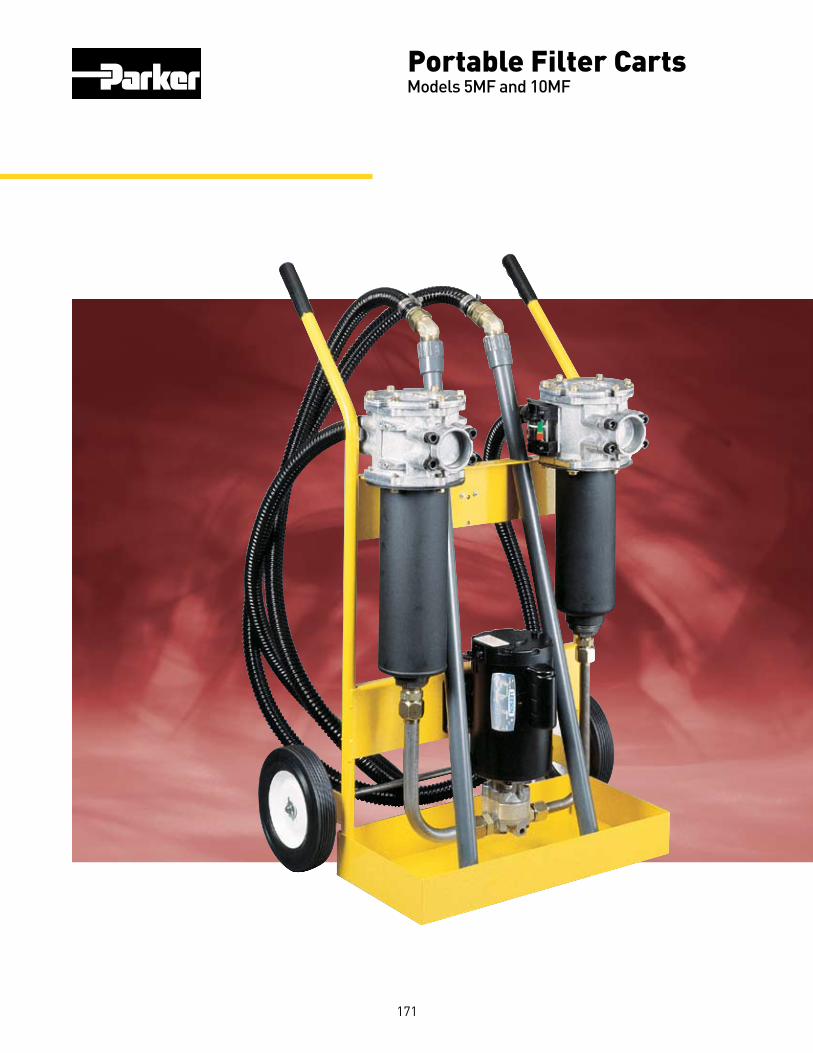
Portable Filter CartsModels 5MF and 10MF zf06
171

5MF and 10MF Portable Filter Cart
Parker Hannifin CorporationHydraulic Filter DivisionMetamora, OH172
Applications for Parker Filter Carts
■ Filtering new fluid before putting into service
■ Transferring fluid from drums or storage tanks to system reservoirs
■ Conditioning fluid that is already in use
■ Complimenting existing system filtration
■ Removing free water from a system
■ For use with fluids such as hydraulic, gear and lube oils
comes into contact with this material, it is removed from the system.
The Parker filter cart uses two high capacity ModuFlow™ filters for long element life and better system protection. The first stage (inlet) filter captures larger particles, while the second stage (outlet) filter controls finer particles or removes water. A rugged industrial quality gear pump gets the job done fast.
Using a Parker portable filter cart is the most economical way to protect your system from the harm that can be caused by contamination.
Parker filter carts are the ideal way to prefilter and transfer fluids into reservoirs or to clean up existing systems.
Fluid should always be filtered before being put into use. New fluid is not necessarily clean fluid. Most new fluids (right out of the drum) are unfit for use due to high initial contamination levels. Contamination, both particulate and water, may be added to a new fluid during processing, mixing, handling and storage.
Water is removed by installing Par-Gel™ elements in the outlet filter. Par-Gel™ elements are made from a polymer which has an extremely high affinity for free water. Once water
Features Advantages Benefits
• Two filters instead of one. • Pump protection and long • Element cost savings and element life. trouble-free service.
• Wide variety of particulate • Capable of getting a fluid to • Avoids excess costs due filter elements available. a desired cleanliness level. to over or under filtration.
• Par-Gel water removal • Removes “free water” from • Gets dirt and water out of elements available. a system. system with one process.
• Heavy duty frame. • Rugged and durable. • Built to last for many hours of use.
• Lightweight and portable. • Easy to move from • One person operation. place-to-place.
• Two flow rates available • Enables use in low or high • Matched to your needs. (5 gpm or 10 gpm). viscosity applications.
• Eleven-foot hose and • Additional hardware • Ready to use as received. wand assemblies included. not necessary.

5MF and 10MF Portable Filter Cart
Parker Hannifin CorporationHydraulic Filter DivisionMetamora, OH173
Dual Filters
■Two-stage filtration for long element life and pump protection
Service Cover
■Top-accessible for easy changing of elements
Elements (not shown)
■Available for both particulate and water removal
Visual Indicator
■Tells you when to change element
Motor
■Industrial brand name
Heavy Duty Frame
■Rugged and built to last
Drip Pan
■Helps keep the work area safe and clean
Electrical Cord (not shown)
■6ft. with on/off switch
■Optional 20 ft. cord with reel
Gear Pump
■Industrial quality
■Quiet operation
■Dependable, long life
Hose & Wand Assembly
■ Ready to use; no additional hardware needed
■ Flexible hoses for tight spots
■ Kink-resistant hose prevents pump cavitation
Features

5MF and 10MF Portable Filter Cart
Parker Hannifin CorporationHydraulic Filter DivisionMetamora, OH174
A
C
B
Dimensions: inches (millimeter)
A - Height: 40.5” (1029)B - Width: 25.5” (648)C - Depth: 19.0” (483)
Specifications
Maximum Recommended Fluid Viscosity: 10MF: 500 SUS (108 cSt) (.85 specific gravity) 5MF: 3000 SUS (627 cSt) (.85 specific gravity)
Visual Indicator: Visual differential type 3-band (clean, change, bypass)
Filter Bypass Valve Settings: Inlet: 3 psid (.2 bar) Outlet: 25 psid (1.7 bar)
Operating Temperatures: Buna N (Nitrile) -40°F to 150°F (-40°C to 66°C)
F3 (high temp option) -15°F to 200°F (-26°C to 93°C)
Electrical Service Required: 10MF - 110/220 volts, 60/50 Hz, single phase, 10/5 amps
5MF - 110/220 volts, 60/50 Hz, single phase, 8/4 amps
Electrical Motor: l0MF - ¾ hp @ 3450 rpm, O.D.P. 5MF - ½ hp @ 1725 rpm, O.D.P. Thermal overload protection
Construction: Cart Frame: Steel Filter Head: Aluminum Filter Bowl: Steel Hoses: PVC (Std.) EDPM (high temp option) Wands: PVC (Std.) Steel tube (high temp option)
Weight (approximate): 110 Lbs. (45.4 kg)

5MF and 10MF Portable Filter Cart
Parker Hannifin CorporationHydraulic Filter DivisionMetamora, OH175
Reservoir Time ProjectedCapacity Required Cleanliness(Gallons) (Hours) Level (ISO)
Efficiency at x,y,zBeta Rating Particle Size Bx = 2 ............................................................50.0% By = 20 ..........................................................95.0% Bz = 75 ..........................................................98.7%
Typical Fluid Cleanliness Filter Cart PerformanceLevel Requirements Fluid cleanliness levels are a function of initialMany manufacturers of hydraulic components have contamination levels, contamination ingression rates,established fluid cleanliness levels for their compo- reservoir size and filter element efficiency. The chartnents. Using a portable filter cart can be a very effective below lists approximate time requirements to achieve way to reach and maintain these cleanliness levels. certain cleanliness levels based on the assumptions noted.
50 0.5 20/18/15 50 1.0 17/15/12 50 2.5 16/14/11 100 1.5 18/16/13 100 2.5 17/15/12 100 4.0 16/14/11 200 2.5 19/17/14 200 3.5 18/16/13 200 5.0 17/15/12 Notes: The results in the chart are based on the following assumption: 1. Initial contamination level is 500,000 particles greater than 10 micrometers per 100 ml of fluid (10MF cart). 2. Inlet filter fitted with 40SA element. outlet with 10C element. 3. System ingression rate equal to 1 X 10⁶ particles greater than 10 micrometers entering the system per minute.
Filter Cart Element Performance Time Averaged Media Filter Beta x/y/z =2/20/75 Capacity Code Media Where x/y/z is: (Grams)
74W Woven Wire 0.00291 * 40W Woven Wire 0.00161 * 40SA Synthetic 40 Micron Nominal2 * 20C Cellulose 20 Micron Nominal2 * 10C Cellulose 6/18/22 Micron 1520Q Microglass II 7.5/12.5/17 Micron 4710Q Microglass II <2/6/9 Micron 4205Q Microglass II <2/<2/3.3 Micron 4602Q Microglass II <2/<2/2 Micron 45
Par-Gel™ Media Water Capacity Model Fluid Viscosity Capacity
5MF 75 SUS 250 ml 200 SUS 140 ml
10MF 75 SUS 190 ml 200 SUS 80 ml
ISO Component Cleanliness LevelServo control valves 16/14/11Proportional valves 17/15/12Vane and piston pumps/motors 18/16/13Directional and pressurecontrol valves 18/16/13Gear pumps/motors 19/17/14 Flow control valvescylinders 20/18/15New fluid 20/18/15
Notes: Multipass test run @ 40 gpm to 25 psid. ANSl/NFPA T3.10/8.8 R1-1990 w/50 ppm anti-static additive *Not Applicable. 1. Not multipass tested- Number shown Is actual pore size in inches. 2. Not multipass tested.
Notes: 1. Par-Gel elements are designed to remove “free water”, which is defined as water that is above a particular fluid’s saturation level. 2. Capacity is very dependent on flow rate and viscosity. Not recommended with fluids in excessof 500 SUS.

5MF and 10MF Portable Filter Cart
Parker Hannifin CorporationHydraulic Filter DivisionMetamora, OH176
Assembly
1) Install hoses to inlet and outlet filters by threading the hose end with the straight thread “o”-ring seal fitting into the filter flange.2) Connect the PVC tube wands to the swivel fitting on the hose end. Whenever servicing the PVC tube wand do not overtorque the metal fittings going into the PVC coupling. Overtorque will result in cracking the coupling. Generally, 1/4 turn beyond handtight is sufficient.
Operating Instructions1) Insert the inlet wand assembly into the supply fluid receptacle (drum/reservoir). The “RF”. filter is the inlet filter.2) Insert the outlet wand assembly into the clean fluid receptacle (drum/reservoir). The “CF” fIlter is the outlet filter.
Caution:Do not kink the hose assemblies, this may result in excessivevacuum or pressure at the pump.
3) Verify that the ON/OFF switch is OFF and plug the cord into a 115V 10A grounded outlet (3 wire). 4) Turn switch to ON position and check outlet wand for oil flow. Allow 30 to 60 seconds for filters to fill with oil. If repeated attempts to obtain oil flow fail, check pump inlet fittings for tightness, remove inlet filter access cover and verify the cover sealing “o”-ring is in place. For very viscous fluids it may be necessary to pour 1 or 2 quarts of fluid into the “RF” inlet filter housing to prime pump initially.5) The condition of the filter element should be monitored by observing the cleanliness indicator on the discharge filter. When the Indicator is in the CHANGE position, both inlet and outlet filter elements MUST be replaced to prevent fluid from going into bypass in the filters.
6) The inlet filter Is provided with a 3PSI bypass spring, and prevents the pump from cavitating If the element is not changed. The outlet filter is provided with a 25PSl bypass spring to prevent excessive pressure which may be harmful to personnel or to the filter cart.
Warning:The filter bypass spring acts as a relief valve for the pump. Do not restrict the discharge hose with a shut-off valve which will defeat the function of the bypass valve, causing excessive pressure, which may be harmful to personnel or to the filter cart.
7) The cleanliness indicator works on differential pressure and will indicate the condition of the element (CLEAN, CHANGE, or BYPASS).
NOTE:The filter cart must be in operation for the indicator to read properly.
Maintenance Instructions1) Turn switch to OFF position and unplug cord from electrical outlet.2) Remove tube wands from oil to prevent siphoning.3) Loosen hex head screws on filter cover. Turn cover to clear screws, remove cover.4) Pull flow diverter assembly from the filter head. Filter element will follow the diverter. a) Replace the cellulose, synthetic or Microglass II elements. Verify replacement. b) Wire mesh elements can be cleaned. Ultrasonic cleaners provide best results.5) Install element on flow diverter and reinstall in filter housing. Make sure diverter “o”-rings seat properly into the head.6) Check to be sure that the notch on the flow diverter lines up with the notch in the head.7) Inspect the cover “o”-ring and replace if necessary.8) Replace cover and tighten hex head screws until they are snug. Do not over-torque these screws. Do not interchange the inlet filter cover with the outlet filter cover. (The inlet filter has a “RF” prefix, the outlet filter has a “CF” prefix).
Problem Cause Solution
Does not start. ON/OFF switch. Turn switch ON, replace switch if defective. No electrical power. Plug in cart. Defective motor. Replace.
Filter housing not filled with oil. Allow pump to run 30 to 60 seconds. Suction leak. Check tightness of inlet fittings. Check “o”-ring in inlet filter cover for nicks. Kink or restriction in inlet hose. Add 1 or 2 quarts of oil to inlet filter. Defective pump. Replace pump.
Element dirty. Replace or clean elements (both filters). Oil extremely cold or viscous. Change element to coarser micron rating. or BYPASS.
No outlet element. Install element. 40 micron element installed Check cart model number to verify correct in outlet filler. element. The inlet filter has a rating “RF” prefix; the ouflet filter has a “CF” preflx.
Trouble Shooting
No oil flow orerratic pump noise.
Indicator does notseem to move.
Indicator readsCHANGE

5MF and 10MF Portable Filter Cart
Parker Hannifin CorporationHydraulic Filter DivisionMetamora, OH177
Filter Cart Replacement Parts
Replacement Element Part Numbers
1 928690 Frame 1 2 928653 Axle 1 3 928650 Wheel 2 4 928651 Handle Grip 2 5 928649 Cord Cleat 1 Opt. 5 928623 Cord Reel 1 6 928731 Pump 1 7 928678 Motor 10MF 1 7 929692 Motor 5MF ó 8 928748 Pipe Reducer 1 9 928728 Tube Fitting 1 10 928652 Adapter Fitting 1 11 928677 Suction Tube Assembly
12 928749 Pipe Reducer 1 13 928729 Adapter Fitting 1 14 928676 Discharge Tube Assembly 15 928727 Tube Fitting 1 16 928663 Hose Assy. - Buna N 2 16 928621 Hose Assy. - Fluorocarbon ó 17 928784 Tube Wand Assy. Buna N 2 17 928620 Tube Wand Assy. Fluorocarbon 18 932187 Name Plate 1 19 RF2-1-**-PP3-YN-F9-1 Inlet Filter - Buna N 1 19 F3-RF2-1-**-PP3-YN-F9-1 Inlet Filter - Fluorocarbon ó 20 CF2-1**-MP25-F9-YN-1 Outlet Filter - Buna N 1 20 F3-CF2-1-**-MP25-F9-YN-1 Outlet Filter - Fluorocarbon ó
Buna Seals Fluorocarbon Media Code (Standard) Seals
74W 924456 925043 40W 924455 925042 40SA 924448 925035 20C 924451 925038 10C 924450 925037 20Q 933742Q 933743Q 10Q 924453Q 925040Q 05Q 924452Q 925039Q 02Q 933068Q 933069Q WR 927584 928908
Item Part No. No. Description Quantity
Item Part No. No. Description Quantity
**Refer to table above
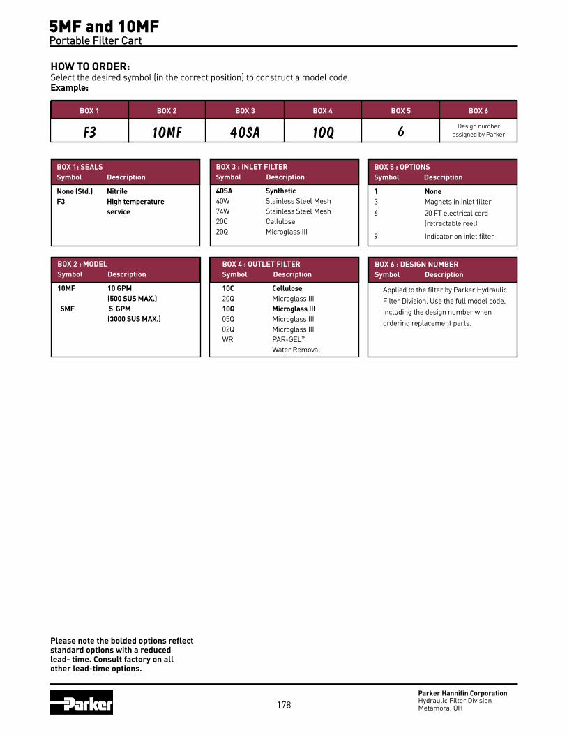
5MF and 10MF Portable Filter Cart
Parker Hannifin CorporationHydraulic Filter DivisionMetamora, OH
HOW TO ORDER:Select the desired symbol (in the correct position) to construct a model code. Example:
BOX 1 BOX 2
10MF
BOX 3
40SA
BOX 4
10Q
BOX 5
6
BOX 6
F3
BOX 1: SEALSSymbol Description
None (Std.) NitrileF3 High temperature service
40SA Synthetic40W Stainless Steel Mesh74W Stainless Steel Mesh20C Cellulose20Q Microglass III
10C Cellulose20Q Microglass III10Q Microglass III05Q Microglass III02Q Microglass IIIWR PAR-GEL™ Water Removal
Applied to the filter by Parker Hydraulic Filter Division. Use the full model code, including the design number when ordering replacement parts.
BOX 2 : MODELSymbol Description
10MF 10 GPM (500 SUS MAX.) 5MF 5 GPM (3000 SUS MAX.)
BOX 3 : INLET FILTERSymbol Description
BOX 5 : OPTIONSSymbol Description
1 None3 Magnets in inlet filter
6 20 FT electrical cord (retractable reel)
9 Indicator on inlet filter
BOX 4 : OUTLET FILTERSymbol Description
BOX 6 : DESIGN NUMBERSymbol Description
178
Design number assigned by Parker
Please note the bolded options reflect standard options with a reduced lead- time. Consult factory on all other lead-time options.

Guardian®
Portable Filtration System zf04
179

Portable Filtration System Guardian®
Parker Hannifin CorporationHydraulic Filter DivisionMetamora, OH
The Guardian portable filtration system is a unique pump/motor/filter combination designed for conditioning and transferring petroleum-based and water emulsion fluids. It protects your system from contamination added with new fluid because new fluid is not necessarily clean fluid. Most new fluids right out of the drum are unfit for use due to high initial concentrations of contaminants. Contamination may be added to a new fluid during processing, mixing, handling, and storage. The Guardian also circulates and “polishes” fluid in your existing systems to reduce the contamination to an acceptable level. There are literally hundreds of applications that the Guardian is suited for, with more being discovered each day. If your system is sensitive to the harmful effects of contamination, then the Guardian may be ideal for you.
Ground Support
Hydraulic Service
Mining
180

Portable Filtration System Guardian®
Parker Hannifin CorporationHydraulic Filter DivisionMetamora, OH
Features Advantages BenefitsLightweight, hand held, compact design (less than 24 Ibs 16” X 8” approximate foot print).
Easy to carry and fits easily on top of 55 gallon drums.
One person operation, capable of getting to hard to reach areas.
Flow rate to 4 gpm. Filters and transfers simultaneously.
One step operation.
Powerful pump/mo-tor combination with Carboxylated Nitrile seals standard.
Handles fluids up to 16,000 SuS viscosity (11,000 SuS -24 VDC).
Reliable performance in a wide variety of operating conditions.
Built-in relief valve with no downstream fluid bypass.
Only filtered fluid reaches downstream components.
100% filtration ensured, even when unattended.
Wide variety of filter elements available.
High capacity 2 micron absolute disposable microglass to 74 micron cleanable wire and water removal.
Maximizes element life between changes.
Clear, wire-reinforced 5’ hose assemblies with wand attachments.
No additional hardware required.
Ready to use and easy to maneuver.
Optional quick disconnect hose connections.
Fast, easy setup and tear-down.
Eliminates messy drips.
Heavy-duty ¼ HP, 115 VAC (230 VAC, 24 VDC- optional) motor with thermal overload protection.
uL recognized and CSA listed, with replaceable brushes.
Safe, reliable performance; field serviceable.
Geroter pump with visible serviceable inlet strainer.
Dirt tolerant design with added protection.
Pump reliability in highly contaminated fluids.
Quiet operation. Less than 70dB noise level @ 3 feet.
Can be used most anywhere with minimal disturbance.
Convenient inlet-to-outlet hose connection.
Contains fluids when transporting.
Clean and safe operation.
Low center of gravity.
Guardian stability. unattended reliability.
Dual motor seals. Added motor protection. Longer motor life.
Auxiliary inlet/outlet ports.
used in place of, or in addition to, standard ports. The outlet can also be used as a sampling port.
Flexibility.
Mobile
Industrial
Marine
181

Portable Filtration System Guardian®
Parker Hannifin CorporationHydraulic Filter DivisionMetamora, OH182
Installation and Specification DataMaximum Allowable Operating Pres-sure (MAOP): 50 psi (3.4 bar) Flow Capacity: up to 4 gpm (15 lpm)Maximum Recommended Fluid Vis-cosity: (.85 specific gravity) 110-120 VAC and 220-240 VAC 16,000 SuS 24VDC 11,000 SuSWarning: Explosion hazard. Do not pump flammable liquids such as gasoline, alcohol, solvents, etc.
Operating Temperatures:Unit: -15°F to 180°F (-26°C to 82°C)Wand/Hose: 25°F to I20°F (-4°C to 49°C)Visual Indicator: differentialpressure type, set at 25 psid.Recommended Fluids: petroleumbased oils, water emulsions, anddiesel fuels.Integral Relief Valve: set at 50 psifor motor protection.Noise Level: <70db at 3 ft.
Electrical Motor: ¼ hp@2500 rpm.24 VDC; 10A max.110-120 VAC; 50/60 Hz; 3A max.220-240 VAC; 50/60 Hz; 1.5A max.Thermal overload protected.Replaceable brushes (500 hours).Weight: approximately 23 lbs. 5 oz.Materials:Housing: cast aluminumCover: die cast aluminumHandle and Indicator: nylon Wands and Hose: PVCFittings: brassSeals: fluorocarbon/ carboxylated nitrile
Guardian Schematic
#10-24 Terminal Studs2-places (24 VDC)
On/offswitch
50.82.00
152.46.00
Alternate customer exchangeable, ½-14 NPT inlet and outlet locations (Plugged).
Inlet
Outlet
1957.68
Motor is uL recognizedand CSA listed
398.515.69
Visible and easilycleanable inlet strainer
Clean inlet strainer as required
18/3 power cord with3 prong plug. 1 ft.length(110/120 VAC).
3 wire (1.5mm2 cross section)power cord, 3 ft. lenth(220/240 VAC).
Quick access, zeroleakage, ¾-11.5 NHgarden hose connections.
Non conductivecarrying handle.
MinimumElement removal clearance.
Removable element.
139.75.50
Vibration isolating rubberfeet 4-pls.
¾”wire reinforced flexibleinlet hose, 5 ft. length. ¾”wire reinforced flexible
outlet hose, 5 ft. length.¾”- 11.5 NH garden hose thread(Outlet).
25 PSI differentialvisual indicator.
208.58.21
¾” lightweight wand assembly, 3 ft. full extended length.
Linear Measure: millimeterinch

Portable Filtration System Guardian®
Parker Hannifin CorporationHydraulic Filter DivisionMetamora, OH183
Guardian Element Performance
Bx = 2 50.0%Bx = 20 95.0%Bx = 75 98.7%Bx = 200 99.5%Bx = 1000 99.9%
Note 1: Guardian not recommended for fluid viscosities greater than 16,000 SuS (11,000 SuS;24VDC)
Note 2: Flows based on Guardian with no element installed
EfficiencyBeta at xRating Particle Size
Guardian Flow vs. Viscosity Performance
Multipass test run at 4 gpm to 35 psid1Reference ratings only. Not multipass tested due to coarseness.* Not applicable
Elements Used Media New Oil ISO ISO Achieved Element Life per 250 gallons
10C 22/20/16 21/19/15 120 gallons 2.08 20Q 22/20/16 21/19/15 486 gallons .51 10Q 22/20/16 19/16/14 407 gallons .61 05Q 22/20/16 17/15/12 330 gallons .75 02Q 22/20/16 15/13/10 316 gallons .79
Estimated Guardian Element Life and Cleanliness LevelsThe following chart shows typical element life (in gallons of oil passed) and cleanliness levels
achieved by standard Parker elements available with the Guardian. Some assumptions have been made.*
* 1. New oil is at ISO 22/20/16. 2. No environment or work ingression. 3. Single pass oil transfer.
NOTE: Data for fluid transfer only. For continuous fluid polishing, lower ISO cleanliness levels will be achieved.
100000
10000
10
1000
100
0 1 2 3 4 5
Visc
osit
y (S
US)
Flow (GPM)
MediaCode
FilterMedia
Time Averaged Beta x/y/z =2/20/75
Where x/y/z is:
DirtCapacity (Grams)
74W Woven Wire 74 micron1 *
40W Woven Wire 40 micron1 *
25W Woven Wire 25 micron1 *
20C Cellulose 20 micron1 *
10C Cellulose 5/8/16 4
20Q Microglass III 7.1/13.7/17.3 16.2
10Q Microglass III 2.7/7.3/10.3 14.4
05Q Microglass III <2/2.1/4.0 14.9
02Q Microglass III <2/<2/<2 14.3

Portable Filtration System Guardian®
Parker Hannifin CorporationHydraulic Filter DivisionMetamora, OH184
Guardian OperationA. Remove all shipping plugs from the hoses and fittings.B. Connect the inlet and outlet hose assemblies to the unit.C. Connect the wand assemblies, if required. D. Place the inlet hose wand assembly into the fluid to be
filtered and/or transferred. E. Place the outlet hose/wand assembly into the container
where the fluid discharge is desired. F. Plug in the unit. G. Flip the switch on the end of the unit to the “on” position.
NOTE: For no-mess transportation, the inlet and outlet hose assemblies can be screwed together by removing the wand assembly.
Element ServicingA. Flip the switch on the end of the unit to the “off” position and
disconnect the electrical plug.B. Rotate the cover counter-clockwise and remove.C. Remove the element from the housing. Discard all
disposable elements. These elements are not cleanable,D. Place the new element In the housing, fitting the o-ring neck
into the large hole at the bottom.E. Inspect the cover o-ring and replace if necessary.F. Replace the cover and hand-tighten.NOTE 1: It is recommended that the Guardian be
cleaned and flushed between uses with dissimilar fluids to prevent fluid mixing.
NOTE 2: Motor brushes may require changeout every 500 service hours
Troubleshooting Guide
Problem Cause SolutionDoes not start. ON/OFF switch. Turn switch on, replace switch if defective. No electrical power. Plug in Guardian, check for tripped circuit breakers, check for blown fuses. Rectifier. Replace if defective. Motor overheats (160°F) Allow motor to cool, thermal overload will automatically reset. Defective motor. Replace motor.
Does not start or erratic Worn motor brushes. Replace motor brushes. motor noise.
Intermittent start/ High viscosity fluids. High viscosity fluids can cause the motor to overheat stop operation. and cycle intermittently. Worn motor brushes. Replace motor brushes. Defective motor. Replace motor.
Hot motor. Pumping under heavy load. It is normal, under a heavy pumping load, for the motor to reach 160°F Defective motor. Replace motor if shell temperature reaches greater than 170°F
No flow or erratic Filter housing not filled with oil. Allow Guardian to run a few seconds.pump noise. Suction leak. Check tightness of inlet fittings and hoses. Check gaskets are in place and are not damaged. Kink or restriction in the inlet hose. Obstructed outlet. Clear outlet. Element dirty. Replace or clean element. Sheared pump key. Replace woodruff key. Defective Guardian. Replace unit.
No flow, erratic pump Gears binding. Disassemble Guardian and thoroughly clean the gear set. noise, motor overheats. Always use the inlet strainer provided to protect the unit. Replace defective gears.
No suction. Plugged strainer. Clean or replace the inlet strainer as required. Clean relief valve. Check for damaged internal o-rings.
Reduced oil flow. High viscosity fluids. High viscosity fluids can cause reduced flow, which is normal. Element dirty. Replace or clean element. Relief valve sticks or is lodged open. Clean relief valve or replace if defective. Partially obstructed inlet or outlet hose. Clear the hose obstruction. Suction leak. Check tightness of inlet fittings and hose. Worn gears. Replace gear set.
Indicator moves to Element dirty, Replace or clean element.RED Area. Oil extremely cold or viscous. Change element to coarser micron rating. Obstructed outlet. Clear outlet obstruction. Defective Indicator. Replace Indicator.
Indicator does not No element. Install element. seem to move. Defective indicator. Replace indicator.
Hoses discolor or Fluid compatibility, Certain fluids, over time, will cause the hoses to discolor. Thisare hard. does not impair their performance. But, some fluids will cause the hoses to become brittle, requiring replacement.
Oil formation under unit. Defective shaft seal. Replace the motor shaft seal.

Portable Filtration System Guardian®
Parker Hannifin CorporationHydraulic Filter DivisionMetamora, OH185
Replacement Parts
Replacement Elements
Media Part No. Box Qty. 02Q 933467Q 2 05Q 932018Q 2 10Q 932017Q 2 20Q 933468Q 2 10C 932016 2 20C 932020 2 25W 922627 1 40W 922628 1 74W 922626 1 WR 932019 2
Parts List
1. Label ....................................Consult Factory 2. Motor, 110-120 VAC .......................... 931913 220-440 VAC ............................ 932381 24 VDC ..................................... 932759 3. SHCS(4),¼-20x1 ................................ 902734 4. Adapter Plate .................................... 931890 5. Housing O-Ring .................................V72041 6. Polypak Seal ...................................... 931921 7. Shadow Plate..................................... 931899 8. Woodruff Key 1/8 x 3/8 . .....................931877 9. SHCS(4), ¼-20 x ¾ ............................. 90267910. Roll Pin 1/8 x ¾ .................................... 903630 11. Geroter Set ........................................ 931873
12. Geroter Ring ...................................... 931903 13. Outlet Plate ....................................... 931900 14. Geroter O-ring ...................................V72135 15. Brass Pipe Plug (2) ½-14 .................. 931920 16. RoIl Pin 1/8 x 5/8 .................................. 903426 17. SHCS (2), ¼-20 x 5/8 ........................... 931889 18. Handle ............................................... 931897 19. Cover .................................................. 931892 20. Cover O-Ring .....................................V72237 21. Element ......................................................... 22. Relief Valve ........................................ 928981 23. Indicator Kit ....................................... 92742224. Housing ............................................. 931838
25. Rubber Bumpers (2) ......................... 93188826. SHCS(2), ¼-20 x ½ ............................ 902907 27. Brass Fitting (2)................................. 931928 28. Gasket (4)........................................... 931956 29. Inlet Screen ....................................... 93192730. Inlet Hose Assembly ......................... 931936 31. Outlet Hose Assembly ...................... 931937 32. Wand Crevice Assembly ................... 931965 33. Wand Adapter Assembly .................. 93196634. Washer (2) ......................................... 926106 35. Quick Disconnect Kit ........................ 932097 (Not Shown)36. Washer .............................................. 93208537. Brush Kit (110/120) ........................... 934329 (220/240 VAC) ................... 934327 (24 VDC) ............................ 932761 Seal Kit ................................................... 932263 Bowl Extension Kit ................................ 932081NOTE: SHCS denotes “socket head cap screw”
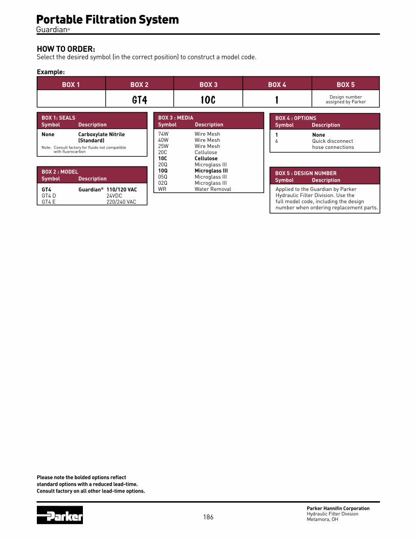
Portable Filtration System Guardian®
Parker Hannifin CorporationHydraulic Filter DivisionMetamora, OH
HOW TO ORDER:Select the desired symbol (in the correct position) to construct a model code.
Example:
BOX 1: SEALSSymbol Description
None Carboxylate Nitrile (Standard)Note: Consult factory for fluids not compatible with fluorocarbon
BOX 5BOX 4
1BOX 3
10C
BOX 2
GT4BOX 1
BOX 2 : MODELSymbol Description
BOX 4 : OPTIONSSymbol Description
1 None6 Quick disconnect hose connections
BOX 5 : DESIGN NUMBERSymbol Description
Applied to the Guardian by Parker Hydraulic Filter Division. use the full model code, including the design number when ordering replacement parts.
74W Wire Mesh40W Wire Mesh25W Wire Mesh20C Cellulose10C Cellulose20Q Microglass III10Q Microglass III05Q Microglass III02Q Microglass IIIWR Water Removal
BOX 3 : MEDIASymbol Description
GT4 Guardian® 110/120 VACGT4 D 24VDC GT4 E 220/240 VAC
186
Design number assigned by Parker
Please note the bolded options reflect standard options with a reduced lead-time. Consult factory on all other lead-time options.

Portable Purification SystemsModels PVS 185, 600, 1200, 1800, 2700 zf05
187

PVS Portable Purification Systems
Parker Hannifin CorporationHydraulic Filter DivisionMetamora, OH
Principles of OperationContaminated oil is drawn into the Parker Portable Purification System by a vacuum of 25 In/Hg. The oil passes through the in-line low watt density heater where the oil is heated to an optimum temperature of 150° F (66°C).
The oil then enters the distillation column where it is exposed to the vacuum through the use of spe-cial dispersal elements. This increases the exposed surface area of the oil and converts the water to vapor form, which is then drawn through the condenser by the vacuum pump.
The water-free oil falls to the bottom of the column and is removed by a heavy duty lube oil pump. This pump forces the dry oil through a final particulate removal filter. Clean oil passes out of the unit, back to the reservoir — and into the system.
Effects of Water ContaminationWater is one of the most common contaminants in a fluid system and one of the most damaging. When water contaminates a system, it can cause serious problems such as:
Corrosion by etching metal
Fluid breakdown, reduction of lubricating properties, additive precipitation, and oil oxidation
Reduced dielectric strength
Abrasive wear in hydraulic components
Free water occurs when oil becomes saturated and cannot hold any more water. This water is usually seen as cloudy oil or puddles of water at the bottom of an oil reservoir. Water which is absorbed into the oil is called dissolved water. At higher temperatures, oil has the ability to hold more water in the dissolved stage due to the expansion of oil molecules. As the oil cools, this ability reverses and free water will appear where not visible before. In addition to temperature, fluid type also determines the saturation point for your system (see chart above).
188

Parker Hannifin CorporationHydraulic Filter DivisionMetamora, OH
PVS Portable Purification Systems
Applications for PVS Portable Purification Systems Paper Mills - Dryer Lubrication - Hydraulic - Compressor Lubrication - Calenders Steel Mills - Bearing Lubrication - Continuous Casters - Press Roll Lubrication Power Generation - Turbine Oil - Transformer Oil - EHC Systems Industrial/Aerospace - Test Stands - Machine Tools
Desiccant Breather
Condenser Vacuum Chamber with Visual Cover
Self Diagnosing Controls
Visual Condensate Holding Tank
Low Watt Density Heater
Moisture Sensor Display
Reverse Phase Switch
Programmable Thermostat
Features Advantages BenefitsVariable flow circuit • Allows oil to heat more quickly • Starts to remove water more quickly
Moisture sensor • Real-time water content indication in % saturation
• At-a-glance visual confirmation
Automatic operation • Unattended use • Designed for 24/7 operation
• Reduces labor costs • Increases operation time
Stainless steel used for all wetted surfaces
• No corrosion • Product reliability
Compact size • Smallest envelope in the industry • Ease of portability
• Fits in tight areas • Encourages use
Clear plexiglass covers on the condensate tank and vacuum chamber
• See the vacuum dehydration process work
• Visual verification of water removal
Desiccant breather • Insures dry, clean intake air • More efficient operation
Reverse phase switch • Enables easy changing of motor rotation if out-of-phase
• Ease of maintenance • Prevents incorrect rotation
Condensate holding tank with optional auto drain
• Large volume for infrequent servicing intervals
• Reduces maintenance costs
Programmable thermostat • Maintains oil within 1°F • Prevents overheating the oil
• Unattended operation
Forklift guides and lifting eyes • Provides safe and secure method of lifting the unit
• Employee safety
Coalescing or packed tower oil dispersal elements
• Flexibility with various fluid viscosities
• Greater efficiency in removing moisture
189

PVS Portable Purification Systems
Parker Hannifin CorporationHydraulic Filter DivisionMetamora, OH
PVS (Vacuum Dehydration) Compared to Other TechnologiesCentrifuge units– Removes free water only; has difficulty breaking stable emulsions; larger envelope dimensions but lower flows; higher initial and operating costs.
Desiccant units– Have limited water removal capability due to absorbing material; only removes air ingressed particles; expensive compared to the volume of water removed.
Coalescer units– Removes free water only; has difficulty breaking stable emulsions; does not work well in viscous fluids (>100 sus); much larger in size compared to PVS.
* When utilizing 2Q media
Potential Contaminant
Solid particulate
Water
Air
Gases
PVS Performance
ISO Cleanliness Code* 14/13/10 Attainable
Removes 100% of free water, 80-90% of dissolved water.
Removes 100% of free air, 90% of dissolved air.
Removes 100% of free gases, 90% of dissolved gases.
Tank Size 60 Gallons (227 liters)
Run Time 62 Minutes
Parker Model PVS 600 (10 GPM)
Water Content (ppm) Start: 10,000 PPM (1.0%) Stop: 50 PPM (0.005%)
Contamination Level Start: ISO 21/18/16 Stop: ISO 16/14/11
Start Stop
Typical Performance
190

Parker Hannifin CorporationHydraulic Filter DivisionMetamora, OH
PVS Portable Purification Systems
S P E C i F i C A T i O n SFlow rate 5 gpm (18.9 lpm)
Height 65" (1651 mm)
Width 33" (838.2 mm)
Length 48" (1219.2 mm)
Weight 650 lbs. (294.8 kg)
Seal material Fluorocarbon (EPR optional)
Condensate tank 4.1 gal (15.5 ltrs)
Dispersal elements 1
Minimum operating capacity 5 gal (18.9 ltrs)
Vacuum (max) 25 In/Hg
Viscosity (max) 500 sus (108 cSt)-Disposable 2150 sus (460 cSt)-Packed Tower
Outlet pressure (max) 60 psi (4.1 bar)
Ports 3/4" JIC (male) inlet 3/4" JIC (male) outlet
FLA (full load amps) 15-41 amps (Depending on voltage used)
PVS 185
REPLACEMENT ELEMENTS
STandaRd CORELESS PaRTICuLaTE (80Cn-2)
02QE (2 micron) 936716Q 05QE (5 micron) 936717Q 10QE (10 micron) 936718Q 20QE (20 micron) 936719Q
OPTIOnaL CORELESSPaRTICuLaTE (IL8-3)
2QE (2 micron) 933734Q 5QE (5 micron) 933612Q 10QE (10 micron) 933735Q
20QE (20 micron) 933736Q
dISPERSaL
disposable 933180 (Coalescing) Packed tower 933553 (Cleanable)
PVS 185 Flow Diagram
.......................................................................................................
.......................................................................................................
.......................................................................................................
.......................................................................................................
.......................................................................................................
.......................................................................................................
.......................................................................................................
.......................................................................................................
.......................................................................................................
.......................................................................................................
.......................................................................................................
.......................................................................................................
.......................................................................................................
.......................................................................................................
Heater
191

PVS Portable Purification Systems
Parker Hannifin CorporationHydraulic Filter DivisionMetamora, OH
PVS 600
PVS 600 Flow Diagram
.......................................................................................................
.......................................................................................................
.......................................................................................................
.......................................................................................................
.......................................................................................................
.......................................................................................................
.......................................................................................................
.......................................................................................................
.......................................................................................................
.......................................................................................................
.......................................................................................................
.......................................................................................................
.......................................................................................................
.......................................................................................................
S P E C i F i C A T i O n SFlow rate 10 gpm (37.9 lpm)
Height 65" (1651 mm)
Width 33" (838.2 mm)
Length 48" (1219.2 mm)
Weight 900 lbs. (408.2 kg)
Seal material Fluorocarbon (EPR optional)
Condensate tank 4.1 gal (15.5 ltrs)
Dispersal elements 2
Minimum operating capacity 6 gal (22.7 ltrs)
Vacuum (max) 25 In/Hg
Viscosity (max) 500 sus (108 cSt) - Disposable
2150 sus (460 cSt) - Packed Tower
Outlet pressure (max) 60 psi (4.1 bar)
Ports 1" JIC (male) inlet 1" JIC (male) outlet
FLA (full load amps) 24-38 amps (Depending on options & voltages)
192
REPLACEMENT ELEMENTS
STandaRd CORELESS PaRTICuLaTE (80Cn-2)
02QE (2 micron) 936716Q 05QE (5 micron) 936717Q 10QE (10 micron) 936718Q 20QE (20 micron) 936719Q
OPTIOnaL CORELESS PaRTICuLaTE (IL8-3)
2QE (2 micron) 933734Q 5QE (5 micron) 933612Q 10QE (10 micron) 933735Q 20QE (20 micron) 933736Q
dISPERSaL disposable 933180 (Coalescing) Packed tower 933553 (Cleanable)

Parker Hannifin CorporationHydraulic Filter DivisionMetamora, OH
PVS Portable Purification Systems
PVS 1200
PVS 1200 Flow Diagram
.......................................................................................................
.......................................................................................................
.......................................................................................................
.......................................................................................................
.......................................................................................................
.......................................................................................................
.......................................................................................................
.......................................................................................................
.......................................................................................................
.......................................................................................................
.......................................................................................................
.......................................................................................................
.......................................................................................................
.......................................................................................................
S P E C i F i C A T i O n SFlow rate 20 gpm (75.7 lpm)
Height 65" (1651 mm)
Width 44" (1117.6 mm)
Length 61" (1549.4 mm)
Weight 1550 lbs. (703.1 kg)
Seal material Fluorocarbon (EPR optional)
Condensate tank 8.3 gal (31.4 ltrs)
Dispersal elements 4
Minimum operating capacity 11 gal (41.6 ltrs)
Vacuum (max) 25 In/Hg
Viscosity (max) 500 sus (108 cSt) - Disposable 2150 sus (460 cSt) - Packed Tower
Outlet pressure (max) 60 psi (4.1 bar)
Ports 1½" NPTF inlet 1" JIC (male) outlet
FLA (full load amps) 30-48 amps (Depending on options & voltages)
REPLACEMENT ELEMENTS
dISPERSaL
Disposable 933180 (Coalescing) Packed tower 933553
(Cleanable)
STandaRd CORELESSPaRTICuLaTE (IL8-3)
02QE (2 micron) 933734Q 05QE (5 micron) 933612Q 10QE (10 micron) 933735Q 20QE (20 micron) 933736Q
193

PVS Portable Purification Systems
Parker Hannifin CorporationHydraulic Filter DivisionMetamora, OH
PVS 1800
REPLACEMENT ELEMENTS
DISPERSAL
Disposable 933180 (Coalescing)
Packed tower 933553 (Cleanable)
STANDARD CORELESSPARTICULATE
02QE (2 micron) 933734Q 05QE (5 micron) 933612Q 10QE (10 micron) 933735Q 20QE (20 micron) 933736Q
...............................................................................................................
...............................................................................................................
...............................................................................................................
...............................................................................................................
...............................................................................................................
...............................................................................................................
...............................................................................................................
...............................................................................................................
...............................................................................................................
...............................................................................................................
...............................................................................................................
...............................................................................................................
...............................................................................................................
...............................................................................................................
S P E C i F i C A T i O n SFlow rate 30 gpm (113.6 lpm)
Height 66” (1676.4 mm)
Width 42” (1066.8 mm)
Length 73” (1854.2 mm)
Weight 2550 lbs. (1156.7 kg)
Seal material Fluorocarbon (EPR optional)
Condensate tank 8.3 gal (31.4 ltrs)
Dispersal elements 8
Minimum operating capacity 18 gal ( 68.1 ltrs)
Vacuum (max) 25 in/hg
Viscosity (max) 500 sus (108 cSt) - Disposable 2150 sus (460 cSt) - Packed Tower
Outlet pressure (max) 60 psi (4.1 bar)
Ports 2” NPTF- inlet 1.5” JIC – outlet
FLA (full load amps) 40-65 amps @ 460 V/60hz
194

Parker Hannifin CorporationHydraulic Filter DivisionMetamora, OH
PVS Portable Purification Systems
PVS 2700
...............................................................................................................
...............................................................................................................
...............................................................................................................
...............................................................................................................
...............................................................................................................
...............................................................................................................
...............................................................................................................
...............................................................................................................
...............................................................................................................
...............................................................................................................
...............................................................................................................
...............................................................................................................
...............................................................................................................
...............................................................................................................
REPLACEMENT ELEMENTS
DISPERSAL
Disposable 933180 (Coalescing)
Packed tower 933553 (Cleanable)
CORELESS 02QE (2 micron) 933734Q 05QE (5 micron) 933612Q 10QE (10 micron) 933735Q 20QE (20 micron) 933736Q
S P E C i F i C A T i O n SFlow rate 45 gpm (170.3 lpm)
Height 66” (1676.4 mm)
Width 42” (1066.8 mm)
Length 73” (1854.2 mm)
Weight 2550 lbs. (1156.7 kg)
Seal material Fluorocarbon (EPR optional)
Condensate tank 8.3 gal (31.4 ltrs)
Dispersal elements 8
Minimum operating capacity 18 gal ( 68.1 ltrs)
Vacuum (max) 25 in/hg
Viscosity (max) 500 sus (108 cSt)- Disposable 2150 sus (460 cSt) – Packed Tower
Outlet pressure (max) 60 psi (4.1 bar)
Ports 3” NPTF - inlet 2” NPTF - outlet
FLA (full load amps) 50-70 amps @ 460 V/60hz
195

PVS Portable Purification Systems
Parker Hannifin CorporationHydraulic Filter DivisionMetamora, OH
PVS Specification Worksheet
1. Application: ______________________________________________________________________
2. Fluid Type: ________________________ Brand: ________________________ Grade: ___________________________ Specific Gravity: _________________
3. Viscosity: Min ______________ SUS/cSt @ ______________ oF/oC Max ______________ SUS/cSt @ ______________ oF/oC Normal ___________ SUS/cSt @ ______________ oF/oC
4. Contamination level: Current ISO level ___ / ___ / ___ Desired ISO level ___ / ___ / ___
5. Water concentration: Current PPM level _____________ Desired PPM level _____________
6. Suction head: Positive/Negative _________________ Ft./meters __________________
7. Operating distance: ______________________________ Ft./meters __________________
8. System fluid operating temperature: ______________ oF/oC Is there a cooler? _____________
9. Operating environment air temperature: (air cooled model) Min _________________________ oF/oC Max ________________________ oF/oC Normal ______________________ oF/oC
10. Water supply temperature: (liquid ring model) Min _________________________ oF/oC Max ________________________ oF/oC Normal ______________________ oF/oC
11. Operating environment above/below sea level: _______________________________ Ft./meters
12. Voltage options: • 230VAC, 3P, 60Hz (185, 600) • 380VAC, 3P, 50Hz (185, 600, 1200, 1800, 2700) • 460VAC, 3P, 60Hz (185, 600, 1200, 1800, 2700) • 575VAC, 3P, 60Hz (185, 600, 1200, 1800, 2700)
13. Available amperage: _______________________________________________________________
14. System volume: __________________________________________________________________
15. Special requirements: ______________________________________________________________
_______________________________________________________________________________
_______________________________________________________________________________
16. Any previous filtration problems with the application: _______________________________________
17. PVS model selected: _______________________________________________________________
*Specification sheet must be completed before order can be entered
196

Parker Hannifin CorporationHydraulic Filter DivisionMetamora, OH
PVS Portable Purification Systems
HOW TO ORDER:Select the desired symbol (in the correct position) to construct a model code. Example:
BOX 1 STD BOX 2 BOX 3 BOX 4 BOX 5 BOX 6 BOX 7 BOX 8 BOX 9
PVS 600 460 DS D 10QE 12KW AC ACD DFLCR
BOX 3: POwer SuPPly *Model Symbol Description
185
230 230VaC, 3P, 60HZ380 380VaC, 3P, 50HZ460 460VaC, 3P, 60HZ575 575VaC, 3P, 60HZ
600380 380VaC, 3P, 50HZ460 460VaC, 3P, 60HZ575 575VaC, 3P, 60HZ
1200380 380VaC, 3P, 50HZ460 460VaC, 3P, 60HZ575 575VaC, 3P, 60HZ
1800380 380VaC, 3P, 50HZ460 460VaC, 3P, 60HZ575 575VaC, 3P, 60HZ
2700380 380VaC, 3P, 50HZ460 460VaC, 3P, 60HZ575 575VaC, 3P, 60HZ
BOX 1: SealS
Symbol Description
none FluorocarbonE8 EPR
BOX 2: BaSe uNIT FlOw raTe
Symbol Description
185 5 GPM (18.9 lpm)
600 10 GPM (37.9 lpm)
1200 20 GPM (75.7 lpm)
1800 30 GPM (113.6 lpm)
2700 45 GPM (170.3 lpm)
BOX 4: VacuuM PuMP
Symbol Description
dS dry sealed
LR Liquid ring
BOX 5: DISPerSal eleMeNT
Symbol Description
d Coalescing (disposable)
P Packed tower (Cleanable)
BOX 6: ParTIculaTe eleMeNT
Symbol Description
2QE 2 Micron Coreless Microglass III
5QE 5 Micron Coreless Microglass III
10QE 10 Micron Coreless Microglass III
20QE 20 Micron Coreless Microglass III
note: above elements are rated for Beta 200+ (99.5% efficiency)
BOX 8: cONDeNSer
Symbol Description
aC air cooled
LC Liquid cooled
BC air and water cooled
BOX 9: OPTIONS
Symbol Description
none Lifting eyes (4)none Moisture Sensornone Variable Flow Circuit3HP 3HP High Viscosity Circuit5dW 5” diameter WheelsaCd auto Condensate drainCdC Condensate drain CounterCE CE MarkedCF Carbon Exhaust FilterCR Cable ReelCSa CSa MarkeddFL dirty Filter LightdPG differential pressure gaugeEXP Explosion Proof (Class I, division II, Zone I and II)ICV Inlet Control ValveIL8 upgrade to IL8-3 coreless filter PnW Pneumatic WheelsRHM Resetable Hour MeterSFI Sight Flow Indicator
197
BOX 7: heaTer
Model Symbol Description
185 12KW 12 KW/3 phase
60012KW 12 KW/3 phase24KW 24 KW/3 phase36KW 36KW/3 phase
120024KW 24 KW/3 phase36KW 36KW/3 phase48KW 48 KW/3 phase
180036KW 36 KW/3 phase48KW 48 KW/3 phase
2700 48KW 48 KW/3 phase
* Consult factory for special voltages

Parker Hannifin CorporationHydraulic Filter DivisionMetamora, OH
198
Notes

Par-Test™
Fluid Analysis zf11
199

Fluid Analysis Par-Test ™
Parker Hannifin CorporationHydraulic Filter DivisionMetamora, OH200
Water Base KitParticle CountPhotomicrographSpectrometric AnalysisViscosity AnalysisNeutralization Analysis
Petroleum Base KitParticle Count PhotomicrographFree Water AnalysisSpectrometric AnalysisViscosity AnalysisWater Analysis (PPM)Neutralization Analysis
Petroleum base fluid kit (single test bottle) 927292
Petroleum base fluid kit (Carton of 10 test bottles) 927293
Water base fluid kit (single test bottle) 932995
How to OrderDescription Part Number
Fluid analysis has proven to be a critical tool for any preventive maintenance program. Fluid analysis is able to identify potential problems that cannot be detected by human senses. A comprehensive fluid analysis program can help prevent major hydraulic or lube oil system failures.
Par-Test is a complete laboratory analysis, performed on a small volume of fluid. The report you receive is a neatly organized three page format. One may quickly analyze the test results of an individual sample and/or look at a trend analysis for up to five different samples. Two types of services are offered through Par-Test, a water base fluid analysis kit or a petroleum base fluid analysis kit. For both types of services the Par-Test kit includes a pre-cleaned glass bottle, mailing container with pre-addressed label, sample information data sheet (to be completely filled out by end user) and the following analysis:
Fluid sampling for Par-Test involves important steps to insure you are getting a representative sample. Often, erroneous sample procedures will disguise the true nature of the system fluid. A
complete sampling procedure is detailed on the back of this brochure. There also is a National Fluid Power Association standard (NFPA T2.9.1-1972) and an American National Standards Institute Standard (ANSI B93.13-1972) for extracting samples
from a fluid power system.

Fluid Analysis Par-Test ™
Parker Hannifin CorporationHydraulic Filter DivisionMetamora, OH
FLUID ANALYSIS REPORT
COMPANY NAME: ABC Corporation
SYSTEM TYPE: Hydraulic
EQUIPMENT TYPE: Press
MACHINE ID: Machine #1
FILTER ID: Parker 10 micron
SAMPLE DATE: 7/12/2004
HOURS: (on oil) 948 (on unit) 2000
SYSTEM VOLUME: 200 Gallons
FLUID TYPE: AW 46
ANALYSIS PERFORMED: N2,S,T,V4,W
Size Counts per ml. ISO Code >4 µm(c) 35000.0 >6 µm(c) 15498.0 >10 µm(c) 6000.0 >14 µm(c) 2600.0 22/21/19 >21 µm(c) 1468.0 >38 µm(c) 754.0 >50 µm(c) 58.0 >70 µm(c) 3.0
PARTEST Fluid Analysis ServiceParker Hannifin Corporation1016 E. Airport Rd.Stillwater, OK 74075Tele: (405)624-0400Fax: (405)624-0401
SAMPLE CODE: 93844 DATE: 09/01/04
Parker Hannifan 16810 Fulton Rd. Co #2 Metamora, OH, 43540
ATTN: Kevin Noe
*The red line in the ISO chart graph indicates recommended cleanliness level.
ALARMS/REMARKS
AUTOMATIC PARTICLE COUNT ISO 11171 FREEWATER
PRESENT
NO
PHOTO ANALYSIS Mag.: 160x Vol 20ml Scale: 1 div = 20 µm
201
X
ISO ChartGraphically illustrates the particle count on a graph. The recommended cleanliness code level, if given on the submittal form, is shown by a broken line on the ISO chart.
Sample DataInformation supplied by the user regarding the fluid to be analyzed. Complete and accurate information is crucial for a useful analysis.
Particle CountResults are reported over 6 different particle size ranges and expressed as an ISO code (modified). The counts are per milliliter of fluid and the reporting is cumulative; ie. The particle count in the >2 micron row includes the number of particles greater than 5, 10, 15, 25 and 50 microns as well as particles between 2-5 microns in size. Particle resuspension method is utilized for water based fluid samples.
Free Water AnalysisDetermines if the water present is beyond the saturation point of the fluid. At the saturation point, the fluid can no longer dissolve or hold any more water. Its appearance becomes cloudy or “milky”. Many hydraulic oils saturate between 500 and 1000 PPM of water.
Photo AnalysisA photomicrograph of a small volume of fluid (20 ml) magnified 100X. This analysis gives a quick glance at the contamination present in the fluid. Each line of the graduated scale represents 20 microns in size.
The full color photomicrograph helps identify particles which would otherwise be grouped by class.
YES

Fluid Analysis Par-Test ™
Parker Hannifin CorporationHydraulic Filter DivisionMetamora, OH
FLUID ANALYSIS REPORT
CST@100C: SSU@210F:
CST@40C: 46.25 SSU@100F: 215.0
WATER CONTENT (PPM): 410.0
TAN: 0.44
WEAR METALSAND ADDITIVES PPM BY WEIGHT STATUS*
The Spectometic Analysis reports the ppm level of 20 different wear metals and additives in the sample. Generally the first 7 and last 5 elements are considered wear elements not normally present in hydraulic oil. Zinc through molybdenum (shaded) represent some common additives in oil. If a baseline oil sample (new oil out of a drum) is provide, then comments on the analyzed sample can be provided on whether the status of the elements are low, normal, or high.
SPECTROMETRIC ANALYSIS
L = LOW N = NORMAL H= HIGH
Viscosity Analysis - ASTM D445
Water Analysis - ASTM D6304
Neutralization Analysis - ASTM D794
PARTEST Fluid Analysis ServiceParker Hannifin Corporation1016 E. Airport Rd.Stillwater, OK 74075Tele: (405)624-0400Fax: (405)624-0401
SAMPLE CODE: 93844 DATE: 09/01/04
Parker Hannifan 16810 Fulton Rd. Co #2 Metamora, OH, 43540
ATTN: Kevin Noe
Comments*Please check spectrometric status for abnormal conditions.
Viscosity at 40C (100F) is reported in Centistokes (cST) and SUS (Saybolt Universal Seconds). The test is conducted in accordance with ASTM D445 procedures for determining the kinematic vis-cosity of fluids
The Total Acid Number (TAN) test measures the acidity of a hydraulic fluid. The higher the number, the more acidic the fluid. Over time this may mean the fluid is becoming oxidized.
The water analysis test shows the actual parts per million of water in a sample. This is known as the Karl Fischer titration test and is conducted in accordance with ASTM D6304.
IRON 120.0 H
COPPER 510.0 H
CHROMIUM < 1.0 N
LEAD < 1.0 N
ALUMINUM 1.0 N
TIN < 1.0 N
SILICON < 1.0 N
ZINC 423.0 N
MAGNESIUM < 1.0 N
CALCIUM 540.0 H
PHOSPHORUS 10.0 L
BARIUM 1.0 N
BORON < 1.0 N
SODIUM < 1.0 N
MOLYBDENUM < 1.0 N
SILVER < 1.0 N
NICKEL < 1.0 N
TITANIUM < 1.0 N
MANGANESE < 1.0 N
ANTIMONY < 1.0 N
202
Viscosity AnalysisViscosity is a very important property of a fluid in terms of system performance. Viscosity expresses the internal friction between molecules in the fluid. Typically a breakdown in viscosity will be seen as an increase. Both SSU at 100º F and cSt at 40º C are reported.
Neutralization AnalysisReferred to as the Total Acid Number (TAN) this titration test measures the acid level of the sample fluid. The production of acidic material causes oxidation degradation or aging of most fluids. This activity is promoted by elevated temperatures, presence of entrained metal particles, and intimate contact with air. It is the rate of increase of the TAN during any given time period that is significant, not just the absolute value.
Water AnalysisKarl Fischer test gives accurate measure of water concentration in the sample fluid. The results are reported in parts per million (PPM) and allow for detection of water levels well below the saturation point.
RemarksQuick statements or alerts about any unusual results from one of the tests reported on this page. Spectrometric Analysis Results obtained by Rotating Disk Electrode (ROE) Spectrometer and reported in terms of parts per million (PPM). Twenty different wear metals and additives are analyzed to help determine the condition of the fluid. The spectrometric test is limited to identifying particles below 5-7 micron in size. Base line (new) fluid samples should be sent in for each different fluid to be analyzed. This will be used to determine the status.
Iron: Ferrous wear particle typically from pumps, gears, cylinders, or rust
Copper: Brass (copper/zinc) and bronze (copper/tin) in bearings and bushings
Chromium: (white non ferrous metal) Chrome from cylinder rods, bearings, valve spools
Lead: Babbitt or copper lead bearings
Aluminum: White nonferrous metal from pump bodies, bushings, bearings, and grinding compounds
Tin: Babbitt bearings, plating
Silicon: Sand/dirt contamination or antifoaming additive in oil
Zinc: Plating or anti-wear additive in oil
Magnesium: Detergent, dispersive additive in oil, bearings, water
Calcium: Dispersant additive or acid neutralizer
Phosphorous: Anti-wear or fire resistant additive in fluid
Barium: Corrosion, rust inhibitor additive in oil
Boron: Detergent, dispersive additive in oil
Sodium: Detergent or coolant additive
Molybdenum: Alloy metal or anti friction additive
Silver: White non ferrous metal
Nickel: Alloy metal
Titanium: White non ferrous metal
Manganese: White non ferrous metal
Antimony: Babbit bearings, greases
WEAR METALS AND ADDITIVES

Fluid Analysis Par-Test ™
Parker Hannifin CorporationHydraulic Filter DivisionMetamora, OH
PARTEST Fluid Analysis ServiceParker Hannifin Corporation1016 E. Airport Rd.Stillwater, OK 74075Tele: (405)624-0400Fax: (405)624-0401
SAMPLE CODE: 93844 DATE: 09/01/04
Parker Hannifan 16810 Fulton Rd. Co #2 Metamora, OH, 43540
ATTN: Kevin Noe
FLUID ANALYSIS REPORT
203
Range Code More than Up to and including 30 5,000,000 10,000,000 29 2,500,000 5,000,000 28 1,300,000 2,500,000 27 640,000 1,300,000 26 320,000 640,000 25 160,000 320,000 24 80,000 160,000 23 40,000 80,000 22 20,000 40,000 21 10,000 20,000 20 5,000 10,000 19 2,500 5,000
Range Code More than Up to and including 18 1,300 2,500 17 640 1,300 16 320 640 15 160 320 14 80 160 13 40 80 12 20 40 11 10 20 10 5 10 9 2.5 5 8 1.3 2.5 7 .64 1.3 6 .32 .64
Trend AnalysisGraphical history for up to 5 samples plotted for 2, 5 and 15 micron and greater size particles. This analysis is a valuable tool for tracking the progress of a system over a given time period.
Sample CodeAssigned to the test kit form for a ready reference. This code can be used to track the sample from start to finish.
ISO Range CodeIndex Number that is associated with a range of particles. Below is a list of the range numbers and the corresponding particle quantities.
NUMBER OF PARTICLES PER ML

Fluid Analysis Par-Test ™
Parker Hannifin CorporationHydraulic Filter DivisionMetamora, OH204
SAMPLING PROCEDUREObtaining a fluid sample for analysis involves important steps to make sure you are getting a representative sample. Often erroneous sampling procedures will dis-guise the true nature of system cleanliness levels. Use one of the following methods to obtain a representative system sample.
I. For systems with a sampling valve
A. Operate system for at least 1/2 hour.B. With the system operating, open the
sample valve allowing 200 ml to 500 ml (7 to 16 ounces) of fluid to flush the sampling port. (The sample valve design should provide turbulent flow through the sampling port.)
C. Using a wide mouth, pre-cleaned sampling bottle, remove the bottle cap and place in the stream of flow from the sampling valve. Do NOT “rinse” out the bottle with initial sample.
D. Close the sample bottle immediately. Next, close the sampling valve. (Make prior provision to “catch” the fluid while removing the bottle from the stream.)
E. Tag the sample bottle with pertinent data; include date, machine number, fluid sup-plier, fluid number code, fluid type, and time elapsed since last sample (if any).
II. Systems without a sampling valve
There are two locations to obtain a sample in a system without a sampling valve: in-tank and in the line. The procedure for both follows:
A. In the Tank Sampling1. Operate the system for at least 1/2 hour.2. Use a small hand-held vacuum pump to
extract sample. Insert sampling device into the tank to one half of the fluid height. You will probably have to weight the end of the sampling tube. Your objective is to obtain a sample in the middle portion of the tank. Avoid the top or bottom of the tank. Do not let the syringe or tubing came in contact with the side of the tank.
3. Put extracted fluid into an approved, pre-cleaned sample bottle as described in the previous sampling valve method.
4. Cap immediately.5. Tag with information as described in
sampling valve method.
B. In-line Sampling1. Operate the system for at least 1/2 hour.2. Locate a suitable valve in the system
where turbulent flow can be obtained (ball valve is preferred). If no such valve exists, locate a fitting which can be easily opened
to provide turbulent flow (tee or elbow).3. Flush the valve or fitting sample point
with a filtered solvent. Open valve or fitting and allow adequate flushing. (Take care to allow for this step. Direct sample back to tank or into a large container. It is not necessary to discard this fluid.)
4. Place in an approved, pre-cleaned sample bottle under the stream of flow per sampling valve methods.
5. Cap sample bottle immediately.6. Tag with important information per the
sampling valve method. Note: Select a valve or fitting where the pressure is limited to 200 PSIG (14 bar) or less.
ON-SITE FLUID ANALYSIS PRODUCT
PLC-3000

Reservoir AccessoriesFiller Breathers, Strainers, Diffusers, Fluid Level / Temperature Gauges ZF07
205

Parker Hannifin CorporationHydraulic Filter DivisionMetamora, OH
Non-Metallic Filler BreathersSingle-Hole and Six-Hole Styles
Specifications:Materials: Body: Non-corrodible glass filled nylon.Valve: Nylon/Nitrile.Dipstick: ABS, acetal Hi/Lo indicators.Filtration Element: Expanded polyurethane foam, 10 micron.Operating Temperatures: -22oF (-30oC) to 195oF (90oC).Seals: Nitrile (single-hole), cork gasket (six-hole).Pressurization Options: 3 psi (0.2 bar).Dipstick: (optional) 7.9 in. (200 mm) or 15.8 in. (400 mm) lengths with adjustable Hi/Lo indicators.
Reservoir Accessories Filler Breathers
Telescopic Strainer
Anti-Splash Design!
(Non-pressurized)US GALS/SEC (air)
0.25
0.20
0.15
0.10
0.05
Flow 1/sec (air)
PSI
3.625
2.9
2.175
1.45
0.275
0
0 1.32 2.64 3.96
Diff
eren
tial P
ress
ure
(bar
)
0 5 10 15
1.2
1.0
0.8
0.6
0.4
0.2
0
Diff
eren
tial P
ress
ure
(bar
)
Flow l/sec (air)
PSI
17.4
14.5
11.6
8.7
5.8
2.9
0
US GALS/SEC (air)0 1.32 2.64 3.96
Differential Pressure Flow Curve(Pressurized)
3psi (.2 bar) valve
Single-Hole Option Six-Hole Option
NOTE: REFER TO UCC PRODUCTIONINSTRUCTIONS FOR ASSEMBLY DETAILSAND PACKING REQUIREMENTS
TANK MOUNTING HOLE Ø63
Ø101
70
271
Ø42
Ø311.22
1.65
3.98
2.76
10.6
7
Ø101
167
10
Ø42
70
Ø101
72
167
A
.164.06x Ø
2.7670
1.651.65
6.57
2.832.
76.3
9
3.98
6.57
3.98
MA
X
Ø42
Ø101
167
10
Ø42
70
Ø101
72
167
A
.164.06x Ø
2.7670
1.651.65
6.57
2.832.
76.3
9
3.98
6.57
3.98
MA
X
Ø42
Linear Measurement= mmin
206
Non-pressurized
AB.98812001.UCAB.98812011.UCAB.98812021.UC
3 psi (.2 bar) without strainer3 psi (.2 bar) with 3.7" (95 mm) strainer3 psi (.2 bar) with telescopic strainer
Six-Hole New Part No. Description
FB1.D1A1A2PFB1.D1A1B2PFB1.D1A1C2P
AB.98210001.UCAB.98210011.UCAB.98210021.UC
Filler breather without strainer Filler breather with 3.7" (95 mm) strainerFiller breather with telescopic strainer
Single-Hole New Part No.
Six-Hole Obs. Part No. Description
Pressurized
(6)-M10x.5(6)-M10x.5(6)-M10x.5
(6)-M10x.5(6)-M10x.5(6)-M10x.5
*Mounting screws for six-hole only
101010
101010
Micron Rating Screws*
Micron Rating Screws*
B.68.206
DIP.FB4
Dipsticks
Pack of (10) x 7.9"
Pack of (10) x 15.8"
Not AvailableNot AvailableNot Available
Single-Hole Part No.
DescriptionNew Part Number
AB.98810001.UCAB.98810011.UCAB.98810021.UC
Six-Hole New Part No.
FB1.A1A1A2PFB1.A1A1B2PFB1.A1A1C2P
Single-Hole Obs. Part No.
FB1.D1B1A2PFB1.D1B1B2PFB1.D1B1C2P
Six-Hole Obs. Part No.
DIP.FB2
–
Obsolete Part Number

Parker Hannifin CorporationHydraulic Filter DivisionMetamora, OH
A
30 A/F HEX
DC
B
Non-Metallic BreathersThreaded Type
Specifications:Materials: Body: Nylon 66.Valve: Nylon/Nitrile.Dipstick: ABS, acetal Hi/Lo indicators.Filtration Element: Expanded polyurethane foam, 10 micron.Operating Temperatures: -22oF (-30oC) to 195oF (90oC).Seals: Nitrile.Pressurization Options: 3 psi (0.2 bar).Dipstick: (optional) 7.9 in. (200 mm) or 15.8 in.(400mm) lengths with adjustable Hi/Lo indicators.
Reservoir Accessories Breathers
B
20 A/F HEX CD
A
Standard Threaded Compact Threaded
Flow 1/sec (air)
0 0.5 1.0 1.5 2.0 2.5 3.0 3.5 4.0 4.5
0.200.180.160.140.120.100.080.060.040.02
0
Diff
eren
tial
Pre
ssur
e (b
ar)
US GALS/SEC (air)0 0.132 0.264 0.396 0.528 0.66 0.792 0.924 1.056 1.188
PSI
2.92.612.322.031.741.451.160.870.580.290
COMPACT THREADED
Anti-Splash Design!
207
Thread size Thread sizeCompact Threaded
DipsticksDescription
Pack of (10) x 7.9"
Pack of (10) x 15.8"
New Part Number
B.68.206
DIP.FB4
New Part NumberAB.683102.UC*AB.68X102.UC*AB.68Y102.UC*AB.68Z102.UC*
Standard ThreadedMicron Rating
10101010
Micron Rating10101010
Thread1/2"NPT1/2" NPT3/4" NPT3/4" NPT
Thread1/4"NPT3/8" NPT1/2" NPT3/4" NPT
"B"2.2" (57 mm)2.3" (57 mm)2.4" (60 mm)2.4" (60 mm)
"A"1.6" (40 mm)1.6" (40 mm)1.6" (40 mm)1.6" (40 mm)
"C".55" (14 mm).49" (12.5 mm).53" (13.5 mm).55" (14 mm)
"D".24" (6 mm).35" (9 mm).35" (9 mm).35" (9 mm)
"B"3.7" (93 mm)3.7" (93 mm)3.8" (95 mm)3.8" (95 mm)
"A"4.0" (101 mm)4.0" (101 mm)4.0" (101 mm)4.0" (101 mm)
"C".51" (13 mm).51" (13 mm).63" (16 mm).63" (16 mm)
"D".39" (10 mm).39" (10 mm).39" (10 mm).39" (10 mm)
Pressurenon-pressurized3 psi (.2 bar)non-pressurized3 psi (.2 bar)
Pressurenon-pressurizednon-pressurizednon-pressurizednon-pressurized
*Pack of (10) pieces.
New Part NumberNot AvailableFB1.C1B3A2PAB.98410201.UCAB.98412201.UC
Obs. Part NumberSB1.A1A2P*SB1.B1A2P*SB1.C1A2P*SB1.D1A2P*
Obs. Part NumberFB1.C1A3A2P–FB1.B1A3A2PFB1.B1B3A2P
Obs. Part Number
DIP.FB2
–

Parker Hannifin CorporationHydraulic Filter DivisionMetamora, OH
Metal Filler BreathersFlange Type
Specifications:Materials: Cap & Plate: Nickel chrome plated steel.Valve: Nylon/Nitrile.Gasket: Cork.Filtration Element: Expanded polyurethane foam, 10 micron.Operating Temperatures: -22oF (-30oC) to 195oF (90oC).Seals: Nitrile.Pressurization Options: none, 5 psi (0.35 bar).
Reservoir Accessories Filler Breathers
3xØ
1.75
1.44
4.33
1.85
1.10
1.63
.16
Ø44.5
36.5
4711
0
Ø28
Ø514.0
41.3
3" Diameter 1.75" Diameter
3.00
1.71
1.95
6.04
2.29
3.27
2.76
.16
Ø76. 2
43.4
58.2
Ø49.5
Ø83
6xØ 4.0
A
153.
5
70
Linear Measurement= mmin
208
New Part No.
AB.1163.10
5561
AB.1380.10
New Part No.
PAB.1730.10.5
Description
3" (76 mm) dia.
3" (76 mm) dia., w/lck lug
1.75" (44.5 mm) dia.
Description
5 psi (.35 bar), 3" (76 mm)dia.
New Part (Cap As.)
CAP.1730.40.5
New Part (Cap As.)
CAP.1163.10
Not Available
CAP.1380.40
Flange Type, Non-pressurized
Flange Type, PressurizedMicron Rtg.
10
Micron Rtg
10
10
10
Screws
(6)-M10x.5
Air Flow
2 gal./sec. (7.5 l/sec.)
Air Flow
2 gal./sec. (7.5 l/sec.)
2 gal./sec. (7.5 l/sec.)
1.3 gal./sec. (5 l/sec.)
Screws
(6)-M10x.5
(6)-M10x.5
(6)-M10x.5
Obs. Part No.
MB1.D1A1B1P
MB1.D1A1B2P
MB1.A1A1B1P
Obs. Part (Cap As.)
CP1.D1A1A1P
Not Available
CP1.A2A1A1P
Obs.Part (Cap As.)
CP1.D1C1A1P
Obs. Part No.
MB1.D1C1B1P

Parker Hannifin CorporationHydraulic Filter DivisionMetamora, OH
Metal BreathersThreaded Type
Specifications:Materials: Cap & Plate: Nickel chrome plated steel.Valve: Nylon/Nitrile.Gasket: Cork.Filtration Element: Expanded polyurethane foam, 10 micron.Operating Temperatures: -22oF (-30oC) to 195oF (90oC).Seals: Nitrile.Pressurization Options: none, 5 psi (0.35 bar).
Reservoir Accessories Breathers
43.4
6
3/4” NPT
35 1.38
Ø76.2
16 65.63
2.561.
71.2
4
3.00
Ø44.5
16 .63
13 56.536
.57
1/4” NPT
2.22.51
.28
1.44
1.75
¾" Threaded ¼" Threaded
Linear Measurement= mmin
209
Description
3" (76 mm) diameter
1.75" (44.5 mm) diameter
Description
5psi (.35 bar) with 3" (76 mm) diameter
Threaded, Pressurized
Threaded, Non-pressurizedMicron Rating
10
10
Thread
3/4" NPT
1/4" NPT
Micron Rating
10
Thread
3/4" NPT
Air Flow
2 gallon/sec. (7.5 l/sec.)
Air Flow
1.3 gallon/sec. (5 l/sec.)
.7 gallon/sec. (2.5 l/sec.)
New Part Number
SAB.1562.10.NPT
SAB.1563.10.NPT
New Part Number
SPA.1731.10.5.NPT
Obs. Part Number
MB1.B1A3A1P
MB1.C1A3A1P
Obs. Part Number
MB1.B1C3A1P

Parker Hannifin CorporationHydraulic Filter DivisionMetamora, OH
Foam PadsIsolates the removal materials from contact with heavy reservoir mist and securely holds materials in place.
Filter PadsSpecially designed filter pads remove solid particulate on upstream side and then regenerate by releas-ing those particles when air flow reverses direction. Lower pad removes airborne contamination and second pad protects against any migration of desiccant.
Air IntakesA total of eight air intakes may be exposed to allow air to freely flow in and out of the TriCeptor.
BreathersDesiccant Type
Specifications:Materials: Casing: Clarified copolymer polypropylene.Cap: Copolymer polypropylene.Stand pipe: PVC.Filtration Element: Polyester, silica gel.Operating Temperatures: -20oF (-29oC) to 250oF (121oC).Seals: None.Maximum Allowable Operating Pressure (MAOP): 5 psi (.34 bar).Particle Removal Efficiency: 98.7% (beta 75) @ 3 micron99.5% (beta 200) @ 4 micron99.9% (beta 1000) @ 5.3 micronWeight: 934330T 1.25 lbs. (.57 kg) each.934331T 1.75 lbs. (.79 kg) each.934332T 2.25 lbs. (1.02 kg) each.
Silica Gel DesiccantHas the highest removal capability by volume of any adsorption method. Indicates condition by changing color.
Foam padInsures filter pad is properly positioned and protects it from external damage.
Molded HousingDurable shock absorbing casing provides reliable service and simple press in mounting.
Features
Reservoir Accessories Breathers
210

Parker Hannifin CorporationHydraulic Filter DivisionMetamora, OH
0 4 8 12 16 20
PSI
D BA
R
2.5
2.0
1.5
1.0
.5
0
3.0
SCFM
Liters/Second
0 1.88 3.78 5.66 7.55 9.44
3.5 .241
.207
.172
.138
.103
.068
.034
0 30 60 90 120 150
PSID
BAR
2.5
2.0
1.5
1.0
.5
0
3.0
3.5 .241
.207
.172
.138
.103
.068
.034
GPM (fluid exchange rate)
41.66
33.53 1.32
101. 6
127.0
9.0
98.55 3.88
1.64
4. 0
5.0
178.07.0
229.0
1“ NPT Thread
Installation
TriCeptor breathers are designed for simple installation on most equipment, regardless of mounting connection. Since TriCeptor breathers are disposable, the threaded connection allows for quick and easy maintenance. Several mounting adapters (shown below) are available to provide the desired mounting. The installation/replacement pro-cess consists of four easy steps:
1. Remove from protective plastic wrap.
2. Remove 1" blue cap from standpipe.
3. Remove foil label to expose the necessary amount of air intake holes.
4. Twist TriCeptor into mounting adapter.
Servicing the TriCeptor breather is also very easy. When the silica gel changes color from blue to a pink, the breather is no longer active and needs to be replaced. Simply remove the unit and discard properly.
Air Flow Performance
The curves below show the air flow performance of the three TriCeptor breathers. To insure the longest life possible, the initial clean pressure drop should not exceed 1.5 psid (.103 bar).
Field Adapter Flange Adapter
Part Number
934330T
934331T
934332T
937546
937463
Model
5" Breather
7" Breather
9" Breather
Field Adapter
Flange Adapter
Reservoir Accessories Breathers
Quantity
6 pcs.
6 pcs.
6 pcs.
1 pc.
1 pc.
Linear Measurement= mmin
211

Parker Hannifin CorporationHydraulic Filter DivisionMetamora, OH
Air inlets are open to meet system requirements, providing
“controlled” breathing. This maximizes the lifespan of
breather.
High performance filter element provides 1-micron filtration.
Color indicating silica gel, absorbs water from incoming
air. During exhalation, dry sys-tem air is passed back through
the silica gel bed partially regenerating the desiccant.
Second filter element protects against any
migration of desiccant dust.
*Patented technology
Rugged aluminum housing.
Foam pad stops oil mist and ensures air is evenly disbursed through the filters and desiccant, providing maximum efficiency for “backflushing” and silica gel regeneration.
Stainless steel standpipe.
Visual indicator window. Replace breather when desiccant color changes from blue to pink.
Foam pads evenly disperse incoming air over filtration and drying media.
Parker's newest air breather is well suited for heavy duty industrial and mobile applications. This new design is equipped to handle high air flow surges as cylinders discharge while providing reliable protection from ingressed water vapor and particulates for clean dry fluids. This also interchanges Pall’s PFD8 series desiccant breather.
Optional breather check valve adator extends breather service life.
Part Number (air breather): 937346
Check vavle breather adaptor: 937347
Dimensions (height x dia): 6.5 in. (165mm) x 5 in. (127mm)
Filtration area: 38 in2 (0.025 m2)
Amount of silica gel: 24 oz. (680 g)
Absorption capacity: 9 0z. (266 ml)
Max. flow rate: 20 cfm @ 1 psid
Filtration: 1µm
Operating temp. range: -200 F (-290 C) to +2500 F (+1210 C)
Hydrophilic agent: Indicating silica gel
Filter media: Polyester/Microglass
Reservoir Accessories Breathers
212

Parker Hannifin CorporationHydraulic Filter DivisionMetamora, OH
168.16.62
MINCANNISTER
REMOVALCLEARANCE
31.81.25130.1
5.12
BreathersSpin-on Type
Specifications:Materials: Low carbon steel.Filtration Element: Cellulose.Operating Temperatures: -40oF (-40oC) to 225oF (107oC).Seals: Nitrile.Weight: 12AT - 1.2 lbs(.54 kg) each. 50AT - 2.3 lbs. (1.0 kg) each.
0 10 20 30 40 50 60 70 80 90 100
12AT
50AT
DIF
FER
ENTI
AL P
RES
SUR
E (P
SI)
AIR FLOW (SCFM) OIL LEVEL CHANGE RATE (GPM)
12AT
0
1
2
3
4
5
6
7
8
9
10
0
1
2
3
4
5
6
7
8
9
10
50AT.1
.2
.3
.4
0 100 200 300 400 500 600
DIF
FER
ENTI
AL
PR
ESSU
RE
(IN
H20
)
Air Rating*
1 micron
2 micron
5 micron
1 micron
2 micron
5 micron
Element
926543
921999
925023
926541
926169
926170
Adaptor Kit
926876
926876
926876
926875
926875
926875
*99% removal efficiency for particles larger than stated size in air.
SizingSelect the proper size cannister for the maximum rate of reservoir draw down or air exchange rate. As a rule of thumb, clean pressure drop should be limited to 0.18 psid (5" H2O).
Recommended cannister change out is after 500 hours of operation. More frequent replacement may be required when operated in heavily contaminated areas such as grinding operations, primary metal mills, and on mobile equipment. Under such conditions, increase replacement frequency to every 250 hours.
Diameter
3.75"
3.75"
3.75"
5.1"
5.1"
5.1"
P/N 926876
P/N 926875
Reservoir Accessories Breathers
12AT
50AT
95.253.75”
148.845.68
MINIMUMREMOVALCLEARANCE
15.7.62
O - RING
1½” - 16 UN
42.71.05
85.13.35
ADAPTER
O - RING
1” - 12 UN
26.71.05
66.82.63
ADAPTER
Linear Measurement= mmin
213
Graphs are for 03C cannisters only. Total pressure drop across cannister, adaptor, and pipe may be found by adding pressure drops below:
+ 1.5% for each inch of 12AT adapter or 3/4" pipe used.+ 3.0% for each 3/4" elbow used.+ 1.0% for each inch of 50AT adapter or 1-1/4" pipe used.+ 2.0% for each 1-1/4" elbow used.

Parker Hannifin CorporationHydraulic Filter DivisionMetamora, OH
Diffusers
Specifications:Operating Temperatures: 195oF (90oC) maximum.Materials: Body & end cap: Zintec. Head: glass-filled nylon.Weight: See chart below.
Benefits:Installing a diffuser in a hydraulic reservoir is a simple change that can make a dramatic difference in system efficiency. With special concentric tubes designed with discharge holes 180o opposed, fluid aeration, foaming and reservoir noise are reduced. Pump life is also extended by reducing cavitation to the pump inlet. The effects of fitting a system with a diffuser are shown below.
Flow without diffuser
Flow with diffuser fitted
Reservoir Accessories Diffusers
A
ØB
MOUNTING THREAD
120° PLAIN AREA
C A/F H
EX
120° PLAIN AREA
214
New PartNumber
2250
2251
2252
2253
Thread(NPT)
3/4"
1"
1 1/2"
2"
Nominal FlowGPM (LPM)
13 (50)
30 (114)
60 (227)
120 (454)
Length "A"Inch (mm)
4.7 (120)
5.0 (127)
7.0 (178)
9.5 (242)
Diameter "B"Inch (mm)
2.4 (62)
3.4 (86)
3.4 (86)
3.4 (86)
WeightLbs. (kg)
.60 (0.27)
.93 (0.42)
1.23 (0.56)
1.52 (0.69)
HEX "C"Inch (mm)
1.81 (46)
2.17 (55)
2.56 (65)
2.95 (75)
Obs. PartNumber
DF1.A2BP
DF1.B4BP
DF1.B6BP
DF1.B9BP

Parker Hannifin CorporationHydraulic Filter DivisionMetamora, OH
Fluid Level/ Temperature Gauges
Specifications:Materials: Lens: Transparent polyamide.Lens base: Nylon 66.Shroud: High impact polystyrene (no aluminum content).Seals: Nitrile.Maximum Operating Pressure: 14.7 psi (1 bar).Operating Temperatures: -22oF (-30oC) to 195oF (90oC).Thermometer Range: 90oF to 210oF (30oC to 90oC).Indicator: Blue alcohol.Fluid Compatibility: Mineral and petroleum based fluids.Mounting: Front or rear fixing, two holes (M10).
Reservoir Accessories Fluid Level/Temperature Gauges
18.5
17
24
76110
43
41.5
3018
17
1.69
1.18
.71
1.63
4.33
3.09
.67
.67
.73 .94
Linear Measurement= mmin
Length 3
215
Part Number Thread Length Description
FL.69121 M10 3 Fluid level and temperature
FL.69221 M10 5 Fluid level and temperature
FL.69321 M10 10 Fluid level and temperature

Parker Hannifin CorporationHydraulic Filter DivisionMetamora, OH
Reservoir Accessories Fluid Level/Temperature Gauges
43
41.5
2274
17
161
127
17
18.5 24
24
1725
4
288
17
43
41.5
2220
2
1.69
2.91
.87
1.63
1.69
7.95
.87
1.63 .67
10.0
0
11.3
4
.67
.94
.67
6.34
5.00
.67
.73 .94
Linear Measurement= mmin
Length 5
Length 10
216
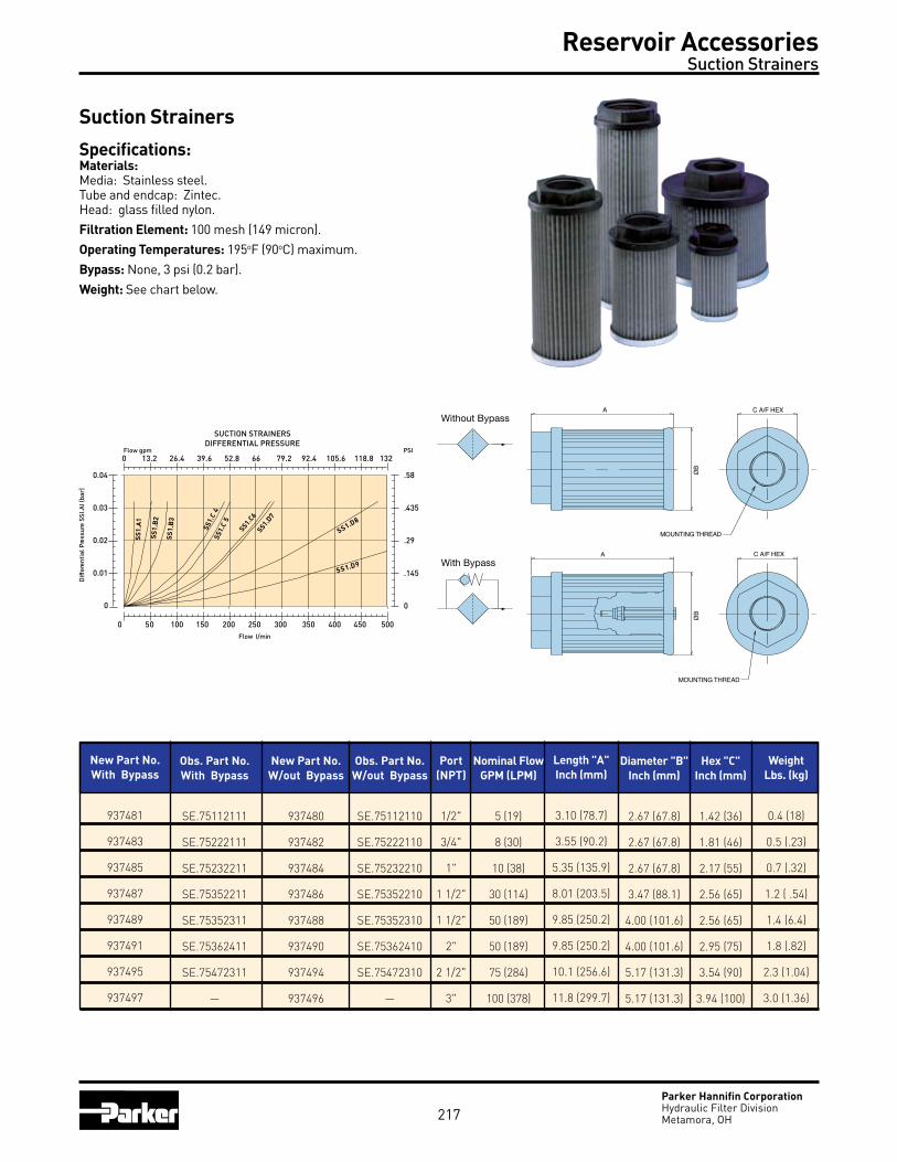
Parker Hannifin CorporationHydraulic Filter DivisionMetamora, OH
Suction Strainers
Specifications:Materials: Media: Stainless steel.Tube and endcap: Zintec.Head: glass filled nylon.Filtration Element: 100 mesh (149 micron).Operating Temperatures: 195oF (90oC) maximum.Bypass: None, 3 psi (0.2 bar).Weight: See chart below.
0 50 100 150 200 250 300 350 400 450 500
SUCTION STRAINERSDIFFERENTIAL PRESSURE
0.04
0.03
0.02
0.01
0
Diff
eren
tial
Pre
ssur
e SS
I.AI (
bar)
Flow l/min
Flow gpm0 13.2 26.4 39.6 52.8 66 79.2 92.4 105.6 118.8 132
PSI
.58
.435
.29
.145
0
SS1.D9
SS1.D8
SS1.D7
SS1.C6
SS1.
C5
SS1.
C4
SS1.
B3
SS1.
B2
SS1.
A1
With Bypass
Without BypassA
ØB
C A/F HEX
MOUNTING THREAD
A
ØB
C A/F HEX
MOUNTING THREAD
Reservoir Accessories Suction Strainers
217
New Part No.With Bypass
937481
937483
937485
937487
937489
937491
937495
937497
Obs. Part No.With Bypass
SE.75112111
SE.75222111
SE.75232211
SE.75352211
SE.75352311
SE.75362411
SE.75472311
—
Port(NPT)
1/2"
3/4"
1"
1 1/2"
1 1/2"
2"
2 1/2"
3"
Nominal FlowGPM (LPM)
5 (19)
8 (30)
10 (38)
30 (114)
50 (189)
50 (189)
75 (284)
100 (378)
Length "A"Inch (mm)
3.10 (78.7)
3.55 (90.2)
5.35 (135.9)
8.01 (203.5)
9.85 (250.2)
9.85 (250.2)
10.1 (256.6)
11.8 (299.7)
Hex "C"Inch (mm)
1.42 (36)
1.81 (46)
2.17 (55)
2.56 (65)
2.56 (65)
2.95 (75)
3.54 (90)
3.94 (100)
WeightLbs. (kg)
0.4 (18)
0.5 (.23)
0.7 (.32)
1.2 ( .54)
1.4 (6.4)
1.8 (.82)
2.3 (1.04)
3.0 (1.36)
Diameter "B"Inch (mm)
2.67 (67.8)
2.67 (67.8)
2.67 (67.8)
3.47 (88.1)
4.00 (101.6)
4.00 (101.6)
5.17 (131.3)
5.17 (131.3)
Obs. Part No.W/out Bypass
SE.75112110
SE.75222110
SE.75232210
SE.75352210
SE.75352310
SE.75362410
SE.75472310
—
New Part No.W/out Bypass
937480
937482
937484
937486
937488
937490
937494
937496
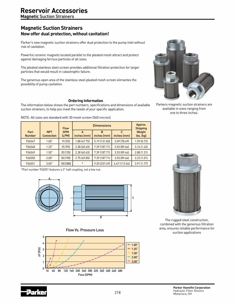
Parker Hannifin CorporationHydraulic Filter DivisionMetamora, OH
Magnetic Suction StrainersNow offer dual protection, without cavitation!
Parker's new magnetic suction strainers offer dual protection to the pump inlet without risk of cavitation.
Powerful ceramic magnets located parallel to the pleated mesh attract and protect against damaging ferrous particles of all sizes.
The pleated stainless steel screen provides additional filtration protection for larger particles that would result in catastrophic failure.
The generous open area of the stainless steel pleated mesh screen elimantes the possibility of pump cavitation.
Parkers magnetic suction strainers are available in sizes ranging from
one to three inches.
Reservoir Accessories Magnetic Suction Strainers
Ordering InformationThe information below shows the part numbers, specifications and dimensions of available suction strainers, to help you meet the needs of your specific application.
NOTE: All sizes are standard with 30 mesh screen (560 micron).
PartNumber
NPTConnection
FlowGPM
(LPM)A
inches (mm)B
inches (mm)C
inches (mm)
Approx.ShippingWeightlbs. (kg)
936547 1.00" 15 (55) 1.88 (47.75) 5.19 (131.83) 3.09 (78.49) 1.59 (0.72)
936548 1.25" 25 (95) 2.38 (60.45) 7.39 (187.71) 3.53 (89.66) 3.16 (1.43)
936549 1.50" 35 (135) 2.38 (60.45) 7.39 (187.71) 3.53 (89.66) 2.88 (1.31)
936550 2.00" 50 (190) 2.75 (69.85) 7.39 (187.71) 3.53 (89.66) 2.22 (1.01)
936551 3.00" 100 (380) * 9.35 (237.49) 4.47 (113.54) 3.91 (1.77)
Dimensions
A
C
B
Flow Vs. Pressure Loss
Flow (GPM)
P (P
SI)
10 40 80 120 160 200 240 280 320 360 400 440 480
5
4
3
2
1
0
1.00”1.25”1.50”2.00”3.00”
218
The rugged steel construction, combined with the generous filtration area, ensures reliable performance for
suction applications
*Part number 936551 features a 3" half coupling, not a hex nut.

Par Gel ™Water Removal Filter Elements zf08
219

Water Removal Filter Elements Par Gel ™
Parker Hannifin CorporationHydraulic Filter DivisionMetamora, OH220
There is more to proper fluid maintenance than just removing particulate matter. You need to remove water as well. Parker has developed Par-Gel water removal elements to be used in combination with particulate filters to provide significant benefits.
■ Less component wear, consequently less component generated contaminants.
■ Significant reduction of costly downtime and replacement of failed components.
■ Increased efficiency of the system, thereby improving machine productivity.
■ Less frequent replacement and disposal of contaminated fluid.
■ Reduced chance of catastrophic failure.
Water as a contaminant.Whether you use a mineral-base or synthetic fluid, each will have a water saturation point. Above this point, the fluid cannot dissolve or hold any more water. This excessive water is referred to as ‘free’ or emulsified water. As little as
Par-Gel filter elements are an effective tool in controlling water related problems in hydraulic power and lubrication systems.
container, or is introduced when the container is opened to add or remove fluid.
In-service. Water can get by worn cylinder and actuator seals, or through reservoir openings. Water can come in contact with these entry points through water based cutting fluids or when water and/or steam are used for cleaning.
.03% (300 ppm) by volume can saturate a hydraulic fluid.Many mineral-base and synthetic fluids, unless
specifically filtered or treated in some way, will contain levels of water above their saturation point.
Water is everywhere!Storage and handling. Fluids are constantly exposed to water and water vapor while being handled and stored. For instance, outdoor storage of tanks and drums is common. Water settles on top of tanks and drums and infiltrates the
.10% WatER 1000 PPm
.03% WatER 300 PPm

Water Removal Filter Elements Par Gel ™
Parker Hannifin CorporationHydraulic Filter DivisionMetamora, OH221
Condensation is also a prime water source. As fluid cools in a reservoir, temperature drop condenses water vapor on inside surfaces, which in turn causes rust. Rust scale in the reservoir eventually becomes particulate contamination in the system.
microbial growth as a contaminant. Once water enters a system, growth of microorganisms begins. Since water is one of the end products of the breakdown of hydrocarbon fluid, once started, the process is somewhat self-sustaining.
Slime is evidence of microbial growth, as is the apparent increase in viscosity of the fluid, obnoxious odor and discolored fluid. The results are: short fluid life, degraded surface finish and rapid corrosion.
Water generated damage and operating problems■ Corrosion■ Accelerated abrasive wear■ Bearing fatigue■ Additive breakdown■ Increased acid level■ Viscosity variance■ Electrical conductivity
Forms of water in fluid■ Dissolved water– below saturation point.■ Free water–emulsified or in droplets*.
Water in the system creates oxides, slimes and resins. Corrosion is an obvious by-product and creates further contaminants in the system.
The effect is compounded, as you now have both particulate contaminant and water working together.
The particulate contamination can be as simple as rust flaking from reservoir walls. Anti-wear additives break down in the presence of water and form acids. The combination of water, heat and dissimilar metals encourages galvanic action. Pitted and corroded metal surfaces and finishes result.
Further complications occur as temperature drops and the fluid has less ability to hold water. As the freeze point is reached, ice crystals form, adversely affecting total system function. Operating functions may become slowed or erratic.
Electrical conductivity becomes a problem when water contamination weakens insulating properties of fluid (decreases dielectric kV strength).
testing your fluid for water. A simple ‘crackle test’ will tell you if there is water in your fluid. Simply take a metal dish or spoon with a small amount of fluid. Apply a flame under the container with a match. If bubbles rise and ‘crackle’ from the point of applied heat, you have free water.
Partest™ fluid analysis. For complete analysis, Parker offers Par-Test fluid analysis. Your Parker representative can supply you with a fluid container, mailing carton and appropriate forms to identify your fluid and its use. An independent lab performs complete spectrometric analysis, particle counts, viscosity and water content.
Results are sent directly to the requester.
* Excessive free water must be removed from the system before filtering is attempted. In systems with gross amounts of water (1% to 2% by volume), settling or vacuum dehydration should be considered before using Par-Gel filter elements.
Typical results of wear due to presence of particulate and water contamination.

Water Removal Filter Elements Par Gel ™
Parker Hannifin CorporationHydraulic Filter DivisionMetamora, OH222
Removing water. Using a Par-Gel water removal element is an effective way of removing free water contamination from your hydraulic system. It is highly effective at removing free water from mineral-base and synthetic fluids.
The Par-Gel filter media is a highly absorbent copolymer laminate with an affinity for water. However, hydraulic or lubrication fluid passes freely through it. The water is bonded to the filter media and forever re-moved from the system. It cannot even be squeezed out.
How many filter elements will I need? Suppose you would like to remove water from contaminated oil stored in a 200 gallon tank. The tank is found to have 1000 ppm of water (very contaminated). The circulation rate will be 10 gpm for the 200 SUS fluid.
Example: How many single length Moduflow™ elements will be needed to reduce the water to normal saturation levels. To find the answer, use the conversion charts and capacity curves for the Moduflow element.1. 1000ppm start - 300ppm finish = 700ppm removed2. 700ppm water x .0001 = .07% .07% x 200 gallons = .14 gallons water total3. Use the capacity curve for Moduflow element P/N 927584. Capacity = 80cc at 200 SUS & 10 gpm to pressure drop of 25 psid. (See graph) 80cc x 0.000264 gal = 0.02 gallons/element cc4. 0.14 gallons total water = 7 elements* 0.02 gallons/element*The replacement value of this fluid may range from $600.00 to $1400.00 ($3 to $7 gallon). At an estimated element cost of $50.00 each, the savings realized would be from $250.00 to $1050.00!
Using Par-Gel filter elements saves money in fluid and replacement component costs. Also, the frequency of fluid disposal and the problems associated with it are greatly reduced.Filter capacity. There are no accepted and approved water capacity testing or reporting standards. Consequently, there is virtually no way to compare one element capacity with another. It is also difficult to simulate a specific application in testing . . . making it hard to predict field performance.
Why the discrepancies? Water removal media capacity is the result of the interplay among four variables: flow rate, viscosity, bypass setting and the media itself.
Here’s an example: two identical elements, testing the same fluid, varying only the flow rate.
Parker technology and expertise at your disposal. Choosing the correct filters can save money and minimize problems caused by particulate and water contaminants in hydraulic and lubricating fluids.
Parker provides hard data and advice on choosing from a wide range of filter configurations, flow patterns and flow pressure capabilities.
Photo above shows ‘dry’ Par-Gel filter media and the same media swollen with absorbed water.
Element A Element A’
Flow Rate: 3 gpm 10 gpm
Viscosity: 75 SUS 75 SUS
Test Capacity: 425 ml 360 ml
This is a 15% reduction in capacity, due to changing only the flow rate! Now, look at what happens when the test flow rate is the same and the viscosity is changed.
Element B Element B’
Flow Rate: 20 gpm 20 gpm
Viscosity: 200 SUS 75 SUS
Test Capacity: 250 ml 550 ml
Twice the capacity can be achieved just by manipulating the test viscosity!Naturally, having a lower bypass valve setting limits the capacity. Since the life
of the element is measured in pressure drop, using higher bypass valve settings will increase apparent life (all other conditions equal).
We recommend 25 psid bypass valves to get adequate life from Par-Gel filter elements.
Capacity also depends on the media itself. That’s why Parker spent two years researching the media used in Par-Gel filter elements. We tested all known media, and worked closely with our suppliers to achieve maximum water absorbency.

Water Removal Filter Elements Par Gel ™
Parker Hannifin CorporationHydraulic Filter DivisionMetamora, OH223
How we report: Our goal is to give our customers usable data. Why show test results at a lower viscosity (65 SUS for example), if the typical application uses 200 SUS fluid? So, we report at 200 SUS to give typical field application capacity, and 75 SUS for competitive comparisons. But keep in mind when comparing, you still have to consider flowrate.
What it all means: You deserve to know how an element will work for you in your applications. So, we test and report our data in such a way that it helps you predict element performance and life.
Be wary of claims that say . . . “this element holds one quart (or one gallon) of water.” What was the test flow rate? fluid viscosity? bypass valve setting? Was it run as a ‘single pass’ or ‘multipass’ test?
Rely on Parker to give you the facts and data you need. Our goal is to better protect your systems and components . . . and we start up-front by telling you what you need to know.Is there any other way to do business? add it all up. Broad selection, competitive prices, off-the-shelf availability, on-time delivery, high-efficiency filter media, reduced system contaminant and longer component life. When you add it all up, we think you’ll agree...
multI-PaSS WatER CaPaCIty
If you Have: Multiply By: To Get:
mg/l 0.00009 %
ppm 0.0001 %
ml 1.0 cc
cc 0.0338 fluid ounces
cc 0.00106 quarts
cc 0.000264 gallons
Fluid PPM %
Hydraulic 300 0.03%
Lubrication 400 0.04%
Transformer 50 0.005%
Conversion Factors
typical Saturation Points
RFP-1/RFP-2 700
600
500
400
300
200
100
0 10 20FLOW (GPM)
CA
PA
CIT
Y (C
C)
30 40 50
200 SUS
200 SUS
75 SUS
75 SUS
IL8-1/IL8-21400
1200
1000
800
600
400
200
0 20 40FLOW (GPM)
CA
PA
CIT
Y (C
C)
60 80 100
200 SUS
200 SUS 75 SUS
75 SUS
40CN-1/40CN-2140
120
100
80
60
40
20
0 5 10FLOW (GPM)
CA
PA
CIT
Y (C
C)
15 20 25
200 SUS
200 SUS 75 SUS
75 SUS
RF7-1 875
750
625
500
375
250
125
0 10 20FLOW (GPM)
CA
PA
CIT
Y (C
C)
30 40 50
200 SUS
75 SUS
RF4-1/RF4-2700
600
500
400
300
200
100
0 10 20FLOW (GPM)
CA
PA
CIT
Y (C
C)
30 40 50
200 SUS
200 SUS
75 SUS
75 SUS
IL8-33500
3000
2500
2000
1500
1000
500
0 20 40FLOW (GPM)
CA
PA
CIT
Y (C
C)
60 80 100
75 SUS
200 SUS
80CN-1/80CN-2525
450
375
300
225
150
75
0 10 20FLOW (GPM)
CA
PA
CIT
Y (C
C)
30 40 50
75 SUS
GUARDIAN®
70
60
50
40
30
20
10
0 2.5 5FLOW (GPM)
CA
PA
CIT
Y (C
C)
7.5 10 12.5
200 SUS
75 SUS
200 SUS
200 SUS
200 SUS
75 SUS

Water Removal Filter Elements Par Gel ™
Parker Hannifin CorporationHydraulic Filter DivisionMetamora, OH
Ideal applications for Par-Gel filter elements:
Guardian® Portable Filtration System
Filter Cart
224
Filter model Series length Element Part Number
RFP-1RFP-2
SingleDouble
927584927585
RF4-1RF4-2
SingleDouble
930156928557
RF7-1RF7-2
SingleDouble
933853932506
IL8-1IL8-2IL8-3
SingleDoubleTriple
929103929109932006
40CN-140CN-2
SingleDouble
931412931414
80CN-180CN-2
SingleDouble
931416931418
Guardian® Single 932019
Parker Par-Gel water removal filter elements are available in these standard Parker filter housings:

Par Fit™ ElementsCompetitive Interchanges zf09
225

Par Fit™ Elements Competitive Interchanges
Parker Hannifin CorporationHydraulic Filter DivisionMetamora, OH
Manufacturer P/N Parker P/N Manufacturer P/N Parker P/N Manufacturer P/N Parker P/N Manufacturer P/N Parker P/N
An extensive range of competitively priced Parker quality replacement filter elements, Par-Fit interchange elements allow the users to acquire all their replacement elements from one quality source regardless of the original equipment manufacturer.
Par-Fit competitive interchange elements must conform to all the same rigorous tests as the standard Parker replacement elements. The elements meet or exceed all specifications for the following tests:
IS02941 Element Collapse/Burst Resistance
IS02942 Fabrication Integrity
IS02943 Material Compatibility
IS03724 Flow Fatigue Resistance
IS04572/ISO16889 Multipass Test
In addition to price and quality, the range of interchange elements available is key to a successful program for the user. Parker has worked diligently over the years to develop a range of elements that will meet this challenge. You can view our complete list of Par-Fit interchange elements in our separate Par-Fit brochure, 2300-PFS, or visit us on the web at the address below.
226

Parker Hannifin CorporationHydraulic Filter DivisionMetamora, OH227
Notes

Parker Hannifin CorporationHydraulic Filter DivisionMetamora, OH228
Notes
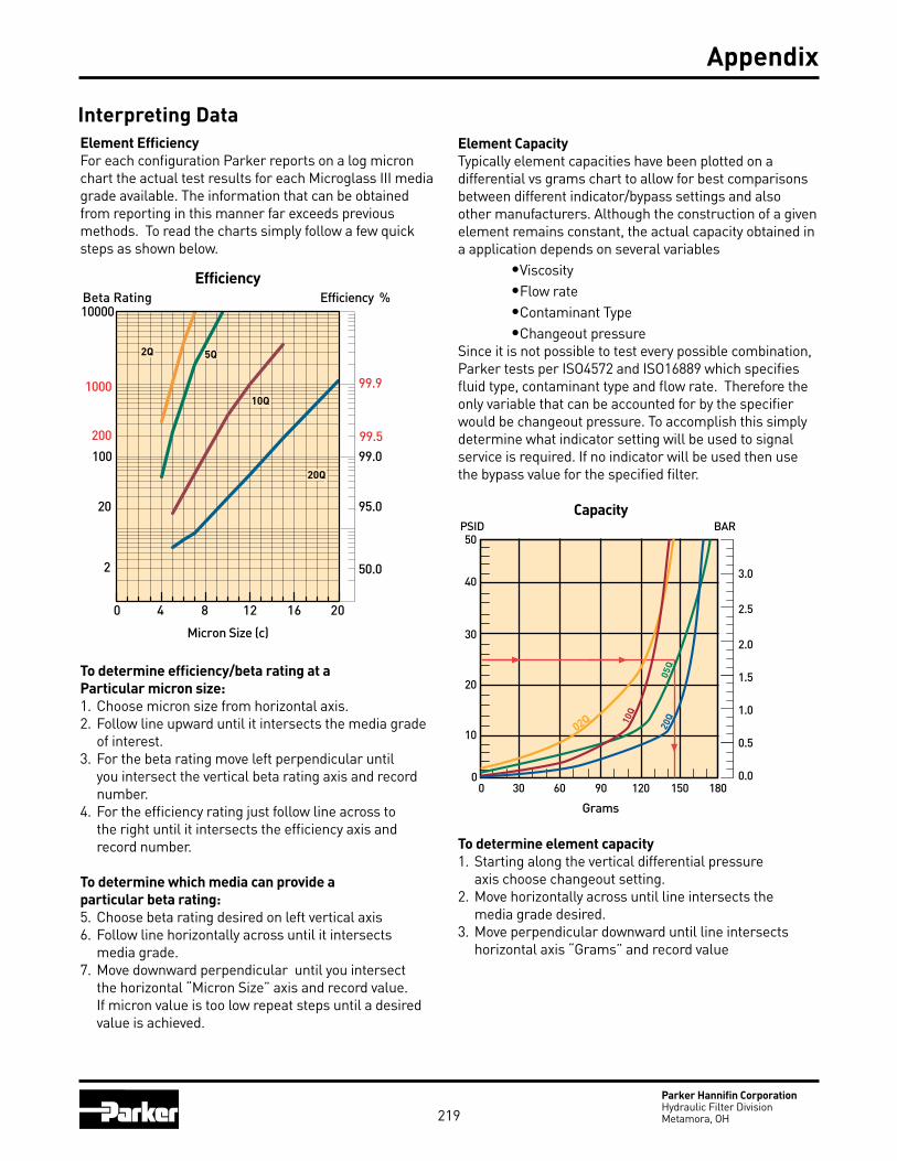
219Parker Hannifin CorporationHydraulic Filter DivisionMetamora, OH
Interpreting DataElement EfficiencyFor each configuration Parker reports on a log micron chart the actual test results for each Microglass III media grade available. The information that can be obtained from reporting in this manner far exceeds previous methods. To read the charts simply follow a few quick steps as shown below.
To determine efficiency/beta rating at a Particular micron size:1. Choose micron size from horizontal axis.2. Follow line upward until it intersects the media grade of interest.3. For the beta rating move left perpendicular until you intersect the vertical beta rating axis and record number.4. For the efficiency rating just follow line across to the right until it intersects the efficiency axis and record number.
To determine which media can provide a particular beta rating:5. Choose beta rating desired on left vertical axis6. Follow line horizontally across until it intersects media grade.7. Move downward perpendicular until you intersect the horizontal “Micron Size” axis and record value. If micron value is too low repeat steps until a desired value is achieved.
Element CapacityTypically element capacities have been plotted on a differential vs grams chart to allow for best comparisons between different indicator/bypass settings and also other manufacturers. Although the construction of a given element remains constant, the actual capacity obtained in a application depends on several variables •Viscosity •Flow rate •Contaminant Type •Changeout pressureSince it is not possible to test every possible combination, Parker tests per ISO4572 and ISO16889 which specifies fluid type, contaminant type and flow rate. Therefore the only variable that can be accounted for by the specifier would be changeout pressure. To accomplish this simply determine what indicator setting will be used to signal service is required. If no indicator will be used then use the bypass value for the specified filter.
To determine element capacity 1. Starting along the vertical differential pressure axis choose changeout setting.2. Move horizontally across until line intersects the media grade desired.3. Move perpendicular downward until line intersects horizontal axis “Grams” and record value
Efficiency %Efficiency
Beta Rating
1000
10000
99.9
99.599.0100
200
20
2 50.0
95.0
Micron Size (c)
2Q
10Q
20Q
5Q
0 4 8 12 16 20
CapacityBAR
Grams
0 30 60 90 120 150 180
50
40
30
20
10
0
3.0
2.5
2.0
1.5
1.0
0.5
0.0
PSID
02Q
05Q
10Q
20Q
Appendix

220Parker Hannifin CorporationHydraulic Filter DivisionMetamora, OH
Flow vs Pressure LossAll performance curves are reported at a standard viscosity of 150 SUS (30 cSt) with element pressure curves independent of the housing. The purpose of reporting individually is to allow for adjustment to other operating viscosities. To adjust for a operating viscosity other then 150 SUS (30 cSt) please use the correction formula below.
High Collapse ElementsIn most cases, filter assemblies are equipped with an internal bypass valve to limit the differential pressure across the element. In some critical applications it may be necessary to equip the filter with a “no bypass” valve which forces all fluid flow to pass through the element. When a filter is equipped with a “no bypass” valve, the element must be able to withstand much higher differential pressures in the event it is not serviced when indicated. Parker high collapse elements are able to withstand 2000 psid (“H” option) or 3000 psid (“X” option) due to their special construction. The high collapse elements are rated for the same efficiencies as the standard elements but also have a higher clean pressure loss. The increase in pressure loss from standard collapse “Q” elements to high collapse “Q” elements varies from media grade and series. To insure adequate element life, a correction factor should be applied to the standard pressure loss curves. Below are the factors that should be applied to the standard element performance curves shown in this catalog. The pressure loss of “H” option elements (2000 psid collapse) may increase as much as 40% over the standard, and the “X” option 3000 psid collapse) as much as 90%.
Correction Factors
Interpreting Data
High Collapse Correction Factors
“QH” Elements (2000 psid) = 1.4 times reported loss
“QX” Elements (3000 psid) = 1.9 times reported loss
Appendix
PSID Element = PSID from catalog x x
PSID Housing = PSID from catalog x
PSID Assembly = PSID Element + PSID Housing
New Viscosity 150
New Specific Gravity.90
New Specific Gravity.90
Viscosity Correction Formula

221Parker Hannifin CorporationHydraulic Filter DivisionMetamora, OH
Filter Media TypesMicroglass IIIThe latest of our media lines, these elements have the highest capacity and efficiency available. The Microglass III is referenced by a “Q” after the micron size ( i.e. 5Q ). Complete information is available for each element size in the catalog. The efficiency is plotted on a beta value versus micron size chart to enable one to find the rating at a specific micron size. The capacity is plotted on a pressure differential versus grams capacity chart. This allows one to find the capacity of the element at the filter’s specific bypass or indicator setting.
Flow data is performed at 150 SUS (32cSt) and plotted separately for the element and housing . Pressure loss for different viscosities can be calculated by using the formula on the opposite page.
CelluloseAn economical type of media (denoted by a “C”) that provides nominal efficiency and capacity. The pore structure of paper media is not efficient for fine filtration or high capacity applications. The data provided for each individual element is limited to flow versus pressure loss. To the left is an efficiency chart which plots what would be considered typical for the various grades of cellulose media.
Stainless Steel Woven WireCommonly referred to as “wire mesh” this filtration medium is typically used in suction filters due to the low flow restriction. Wire mesh elements are unique in that they are designed to be cleaned and reused. These elements are rated for efficiency based on the pore size diameter of the mesh and are denoted by a “W” after the micron rating. For example a 74W element would have a nominal rating of 74 micron based on the diameter of the mesh pores. This should not be confused with “mesh” ratings which are the number of wire strands per inch. Mesh ratings can be correlated to micron ratings, see “Micrometer Conversions” on page 224.
As shown in the chart, cellulose elements are not nearly as efficient as Microglass III elements. They are rated for nominal filtration, typically 50% efficient at rated size. Due to the low particle capture efficiency of 20C cellulose elements, it is not practical to plot on the chart. The 20C elements could be considered a Beta20 = 2 (50% efficient at 20 micron). The same limitations exist with the stainless steel mesh elements.
Efficiency %Efficiency
Beta Rating
1000
10000
99.9
99.599.0100
200
20
2 50.0
95.0
Micron Size (c)
2Q
10Q
20Q
5Q
0 4 8 12 16 20
Appendix
Media Material Capture Efficiency Dirt Holding Capacity Differential Pressure Life In a System Initial Cost
FIberglasss High High Moderate High Moderate
Cellulose Moderate Moderate High Moderate Low
Wire Mesh Low Low Low Moderate High
General Comparison Of Filter Media

222Parker Hannifin CorporationHydraulic Filter DivisionMetamora, OH
Definitions
Absolute Rating:The diameter of the largest hard spherical particle that will pass through a filter under specified test conditions. This is an indication of the largest opening in the filter element. Hydraulic Filter Division defines absolute as 99.5% removal (beta 200) at a given particle size.
Absorb/Absorption:The process of a fluid being taken into the pores of a solid.
Adsorb/Adsorption:To collect and hold a fluid on the surface of a solid.
Beta Ratio:The ratio of the number of particles of a given size and larger of a filter to the number of particles of the same size and larger downstream.
Bubble Point:Pressure drop in inches of water required to expel the first steady (continuous) stream of bubbles from a horizontal disc of wetted filter medium or a filter cartridge immersed in a liquid (usually alcohol). A bubble point test is used to test the integrity of cartridge construction to compare relative porosities of a filter media or monitor product consistency as a quality control method.
Bypass:Fluid flowing through a passage other than the filter medium and/or leakage around filter media seals.
Burst:An outward structural failure of the filter element caused by excessive differential pressure.
Cleanliness Codes:A representation of a fluids contamination level based on a series of index numbers that refer to a table of concentration values.
Collapse Pressure:An inward structural failure of the filter element caused by excessive differential pressure.
Contaminant:Undesirable insoluble solid or gelatinous particles present in fluid.
Crest:The outer fold of a pleat.
Differential Pressure/Pressure Drop:Difference in pressure between two points in a system. In filters, this is typically measured between the inlet and outlet of the filter housing.
Dissolved Water:Water capable of being held by the fluid in solution. The amount held must be below the saturation point.
Duplex Filter:An assembly of two filters with valving for the selection of either element.
Efficiency:The ability of the filter element to remove particles from the filter stream. Efficiency = (1-1/beta)100.
Appendix
Beta Ratios/EfficienciesBeta Ratio Capture Efficiency
(at a given particle size) (at same particle size)
1.01 1.0%
1.1 9.0%
1.5 33.3%
2.0 50.0%
5.0 80.0%
10.0 90.0%
20.0 95.0%
75.0 98.7%
100 99.0%
200 99.5%
1000 99.9%

223Parker Hannifin CorporationHydraulic Filter DivisionMetamora, OH
Effluent:The fluid that has passed through the filter.
Filter Medium:The permeable material used for a filter that separates particles from a fluid passing through it.
Flow Fatigue:The ability of a filter element to withstand structural failure of the filter medium due to flexing of the pleats caused by cyclic differential pressure.
Free Water: Water droplets or globules in a system that tend to accumulate at the bottom of a system’s fluid because it exceeds the solubility of the fluid.
Influent:Fluid entering the inlet of a filter.
In-Line Filter:A filter in which the inlet, outlet and element are in a straight axis.
L-Type Filter:A filter in which the inlet and outlet port axis are at right angles, and the filter element axis is parallel to either port axis.
Laminar Flow:Flow rate at which liquid is in a nonturbulent state (10ft/sec) and should not exceeded to maintain filtration integrity and consistency.
Media Migration:Contamination of the effluent by fibers or other material of which the filter is constructed.
Micron:A unit of length. Correct term is micrometer (µm), which is .000039 inch. Human eye can see a 40 micrometer particle.
Neutralization Number:A measure of the acidity or basicity of a fluid, this includes organic an inorganic acids or bases, or combination thereof.
Nominal Rating:Micron size removed at a given efficiency under a manufacturer’s defined test condition. An arbitrary term assigned by manufacturers which varies and has therefore depreciated in value.
Pinched Pleat:A pleat closed off by excessive differential pressure or crowding, thus reducing the effective area of the filter element.
Pleats:a series of folds in the filter medium usually of uniform height and spacing designed to maximize effective area.
Pressure Line Filter:A filter located in a line conducting working fluid to a working device or devices.
Return Line Filter:A filter located in the line which is conducting working fluid form working devices to a reservoir.
Root:The inside fold of a pleat.
Suction Filter:A filter located in the intake line of a pump where the fluid is below atmospheric pressure.
T-Type Filter:A filter in which the inlet and outlet port axes are in a straight line, and the filter element axis is perpendicular to this line.
Varnish:Materials generated by the hydraulic fluid due to oxidation, thermal instability, or other reactions. These materials are insoluble in the hydraulic fluid and are generally found as brownish deposits in the work surfaces.
Y-Type Filter:A filter in which the inlet and outlet port axes are in a straight line, and the filter element is at an acute angle to this line.
Definitions
Appendix

224Parker Hannifin CorporationHydraulic Filter DivisionMetamora, OH
Note: Lower limit of visibility (naked eye)—40µm
Relative Size of ParticlesMagnification 500x
Linear Equivalents1in = 25.4 mm = 25,400 µm1mm = 0.0394 in = 1,000 µm1µm = 1/25,400 in = 0.001 mm1µm = 3.94 x 10⁻⁵ in = 0.000039 in
FormulasVelocity (ft per sec) = 0.4085 x gpm d2 (ID in)
Conversion Rates1 cu ft = 7.48 gal1 gal = 231 cu in2 cu ft water = 62.42 lb1 gal water = 8.34 lb1 US gal = 0.833 lmp gal1 lb/in2 = 2.31 ft of water = 2.036 in Hg°F = 9/5°C+32
Metric Conversion Formulasmm = inches x 25.4m = feet x 0.3048cm3 = cu in x 16.39m3 = cu ft x 0.028kg = pounds x 0.454kPa = psi x 6.895lpm = gpm x 3.785°C = 5/9 (°F-32)
■ Micrometer Comparisons
74µm
40µm2µm
149µm
Micrometer Conversions
10µm
25µm
Appendix
US and ASTM Std Sieve Number
Actual Opening(in)
(µm)
10 0.0787 2000
12 0.0661 1680
14 0.0555 1410
16 0.0469 1190
18 0.0394 1000
20 0.0331 840
25 0.0280 710
30 0.0232 590
35 0.0197 500
40 0.0165 420
45 0.0138 350
50 0.0117 297
60 0.0098 250
70 0.0083 210
80 0.0070 177
100 0.0059 149
120 0.0049 125
140 0.0041 105
170 0.0035 88
200 0.0029 74
230 0.0024 62
270 0.0021 53
325 0.0017 44
400 0.00142 36
550 0.00099 25
625 0.00079 20
1,250 0.000394 10
1,750 0.000315 8
2,500 0.00097 5
5,000 0.000099 2.5
12,000 0.0000394 1
Substance (µm)
Table Salt 100
Human Hair (average dia) 50-70
White Blood Cell 25
Talcum Powder 10
Cocoa 8-10
Red Blood Cell 8
Bacteria (cocci) 2

225Parker Hannifin CorporationHydraulic Filter DivisionMetamora, OH
To Convert Multiply by To Obtain A atmospheres 33.9 ft of water (at 4×C) atmospheres 29.92 in mercury (at 0×C)
B barrels (US liquid) 31.5 gallons barrels (oil) 42 gallons (oil) bars 0.9869 atmospheres bars 14.5 pounds/sq in
C centimeters 0.03281 feet centimeters 0.3937 inches centimeters 0.00001 kilometers centimeters 0.01 meters centimeters 0.01094 yards centimeters 10,000 microns cubic centimeters 0.00003531 cubic feet cubic centimeters 0.06102 cubic inches cubic centimeters 0.000001 cubic meters cubic centimeters 0.001 liters cubic centimeters 0.002113 pints (US liquid) cubic centimeters 0.001057 quarts (US liquid) cubic feet 28,320 cubic centimeters cubic feet 1,728 cubic inches cubic feet 0.02832 cubic meters cubic feet 0.03704 cubic yards cubic feet 7.48052 gallons (US liquid) cubic feet 28.32 liters cubic feet 59.84 pints (US liquid) cubic feet 29.92 quarts (US liquid) cubic feet/min 62.43 pounds water/min cubic feet/min 1.698 cubic meters/hr cubic feet/sec 448.831 gallons/min cubic inches 16.39 cubic centimeters cubic inches 0.0005787 cubic feet cubic inches 0.00001639 cubic meters cubic inches 0.00002143 cubic yards cubic inches 0.004329 gallons cubic inches 0.01639 liters cubic meters 35.31 cubic feet cubic meters 61,023 cubic inches cubic meters 264.2 gallons (US liquid) cubic meters 1000 liters cubic meters/hour 4.4 gallons (US)/min cubic meters/hour 0.588 cubic feet/min
To Convert Multiply by To Obtain F feet 30.48 centimeters feet 0.0003048 kilometers feet 0.3048 meters feet 304.8 millimeters feet of water 0.0295 atmospheres feet of water 0.8826 inches of mercury feet of water 62.43 pounds/sq ft feet of water 0.4335 pounds/sq in feet/minute 0.01667 feet/second
G gallons 3,785 cubic centimeters gallons 0.1337 cubic feet gallons 231 cubic inches gallons 3.785 liters gallons (liq br imp) 1.20095 gallons (US liquid) gallons (US) 0.83267 gallons (Imp) gallons of water 8.337 pounds of water gallons/min 0.002228 cubic feet/sec gallons/min 0.06308 liters/sec gallons/min 8.0208 cubic feet/hr grams 0.001 kilograms grams 0.002205 pounds grams/cm 0.0056 pounds/in grams/sq in 45.71 ounces/sq yd
I inches 2.540 centimeters inches 0.02540 meters inches 25.4 millimeters inches of mercury 0.03342 atmospheres inches of mercury 1.133 feet of water
K kilograms 2.2046 pounds kilograms 0.009842 tons (long) kilograms 0.001102 tons (short) kilograms/sq cm 2,048 pounds/sq ft kilograms/sq cm 14.22 pounds/sq in kilograms/sq meter 0.00009678 atmospheres kilograms/sq meter 0.00009807 bars kilograms/sq meter 0.003281 feet of water kilograms/sq meter 0.002896 inches of mercury kilograms/sq meter 0.2048 pounds/sq ft kilograms/sq meter 0.001422 pounds/sq in
Measurement Conversion Tables
Appendix

226Parker Hannifin CorporationHydraulic Filter DivisionMetamora, OH
To Convert Multiply by To Obtain L liters 0.2642 gallons (US liquid) liters 2.113 pints (US liquid) liters 1.057 quarts (US liquid) liters/min 0.0005886 cubic ft/sec liters/min 0.004403 gallons/sec liters/hour 0.004403 gallons (US)/min
M meters 3.281 feet meters 39.37 inches meters 0.001 kilometers meters/min 3.281 feet/min meters/min 0.05468 feet/sec microns 0.000001 meters mils 0.00254 centimeters mils 0.000083333 feet mils 0.001 inches mils 0.0000000254 kilometers
O ounces 28.349 grams ounces 0.0625 pounds ounces (fluid) 1.805 cubic inches ounces (fluid) 0.02957 liters ounces/sq in 0.0625 pounds/sq in ounces/sq yard 20.83 pounds/3000 sq ft
P pints (liquid) 0.125 gallons pints (liquid) 0.4732 liters pints (liquid) 0.5 quarts (liquid) pounds 453.59 grams pounds 16 ounces pounds/sq ft 0.0004725 atmospheres pounds/sq ft 0.01602 feet of water pounds/sq ft 0.01414 inches of mercury pounds/sq in 0.06804 atmospheres pounds/sq in 2.307 feet of water pounds/sq in 2.036 inches of mercury pounds/sq in 0.0145 kilo pascals (kPa) pounds/sq in 27.684 inches water column pounds/3000 sq in 0.048 ounces/sq yard
To Convert Multiply by To Obtain Q quarts (liquid) 0.03342 cubic feet quarts (liquid) 57.75 cubic inches quarts (liquid) 0.0009464 cubic meters quarts (liquid) 0.25 gallons quarts (liquid) 0.9463 liters
S square centimeters 0.001076 square feet square centimeters 0.1550 square inches square centimeters 0.0001 square meters square feet 144 square inches square feet 0.0929 square meters square inches 0.006944 square feet square inches 0.0007716 square yards square meters 10.76 square feet square meters 155 square inches square meters 1.196 square yards square yards 9 square feet square yards 1,296 square inches square yards 0.8361 square meters
Measurement Conversion Tables
Appendix
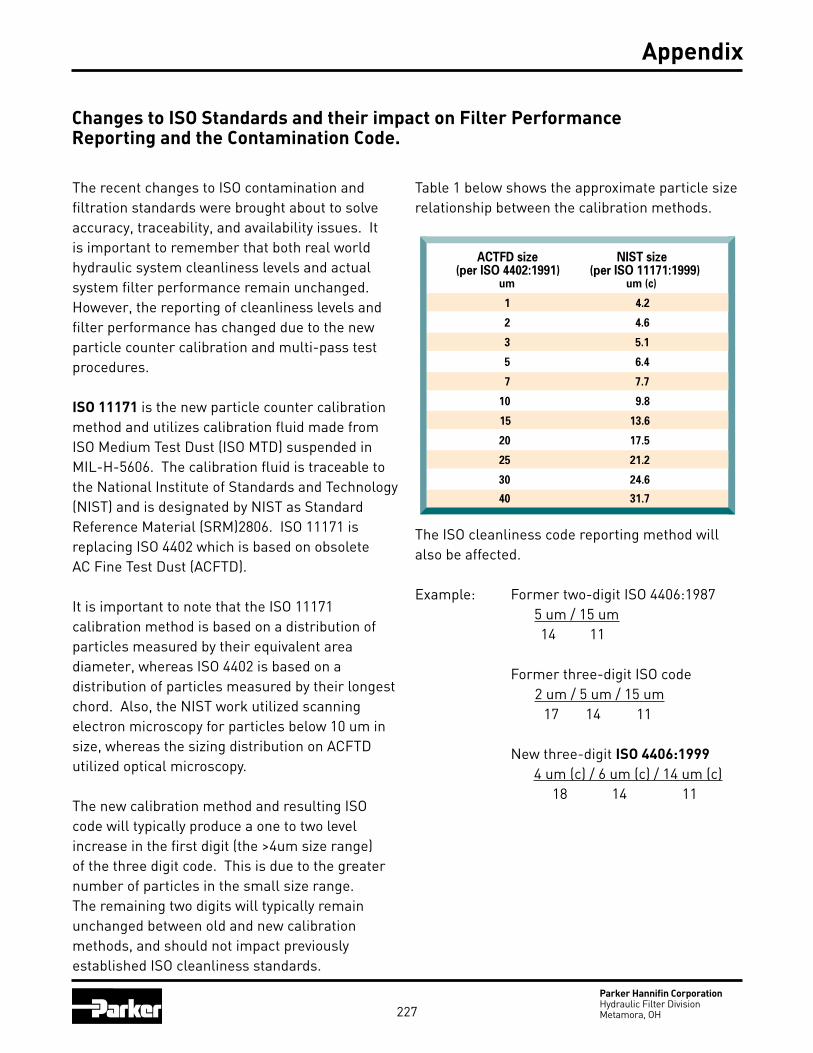
227Parker Hannifin CorporationHydraulic Filter DivisionMetamora, OH
Appendix
Changes to ISO Standards and their impact on Filter PerformanceReporting and the Contamination Code.
The recent changes to ISO contamination and filtration standards were brought about to solve accuracy, traceability, and availability issues. It is important to remember that both real world hydraulic system cleanliness levels and actual system filter performance remain unchanged. However, the reporting of cleanliness levels and filter performance has changed due to the new particle counter calibration and multi-pass test procedures.
ISO 11171 is the new particle counter calibration method and utilizes calibration fluid made from ISO Medium Test Dust (ISO MTD) suspended in MIL-H-5606. The calibration fluid is traceable to the National Institute of Standards and Technology (NIST) and is designated by NIST as Standard Reference Material (SRM)2806. ISO 11171 is replacing ISO 4402 which is based on obsolete AC Fine Test Dust (ACFTD).
It is important to note that the ISO 11171 calibration method is based on a distribution of particles measured by their equivalent area diameter, whereas ISO 4402 is based on a distribution of particles measured by their longest chord. Also, the NIST work utilized scanning electron microscopy for particles below 10 um in size, whereas the sizing distribution on ACFTD utilized optical microscopy.
The new calibration method and resulting ISO code will typically produce a one to two level increase in the first digit (the >4um size range) of the three digit code. This is due to the greater number of particles in the small size range. The remaining two digits will typically remain unchanged between old and new calibration methods, and should not impact previously established ISO cleanliness standards.
ACTFD size NIST size(per ISO 4402:1991) (per ISO 11171:1999)
um um (c)
1 4.2
2 4.6
3 5.1
5 6.4
7 7.7
10 9.8
15 13.6
20 17.5
25 21.2
30 24.6
40 31.7
Table 1 below shows the approximate particle size relationship between the calibration methods.
The ISO cleanliness code reporting method will also be affected.
Example: Former two-digit ISO 4406:1987 5 um / 15 um 14 11
Former three-digit ISO code 2 um / 5 um / 15 um 17 14 11
New three-digit ISO 4406:1999 4 um (c) / 6 um (c) / 14 um (c) 18 14 11

228Parker Hannifin CorporationHydraulic Filter DivisionMetamora, OH
Changes to ISO Standards and their impact on Filter PerformanceReporting and the Contamination Code, continued.
ISO 16889 is the new multi-pass test standard for measuring filter performance and utilizes ISO MTD as the contaminant challenge. This standard is replacing ISO 4572 which utilized ACFTD. See the following graphs below for filtration beta ratio comparisons on our 2Q, 5Q, 10Q, and 20Q Microglass III media. The graphs reflect multi-pass test results using ISO 4572 with ACFTD and the revised ISO 16889 using ISO MTD.
FILTRATION RATIOS FOR 2Q MEDIA
1
10
100
1000
10000
0 1 2 3 4 5 6 7
FILT
RAT
ION
RAT
IO(B
ETA)
200 ISO 16889
ISO 4572
FILTRATION RATIOS FOR 5Q MEDIA
1
10
100
1000
10000
PARTICLE SIZE um or um(c)
FILT
RAT
ION
RAT
IO(B
ETA)
200
0 1 2 3 4 5 6 7 8 9 10
ISO 4572
ISO 16889
FILTRATION RATIOS FOR 10Q MEDIA
1
10
100
1000
10000
PARTICLE SIZE um or um(c)
FILT
RAT
ION
RAT
IO(B
ETA) 200
0 2 4 6 8 10 12 14 16
ISO 16889ISO 4572
FILTRATION RATIOS FOR 20Q MEDIA
1
10
100
1000
10000
PARTICLE SIZE um or um(c)
FILT
RAT
ION
RAT
IO(B
ETA) 200
0 5 10 15 20 25 30
ISO 16889
ISO 4572
Appendix

229Parker Hannifin CorporationHydraulic Filter DivisionMetamora, OH
Notes

230Parker Hannifin CorporationHydraulic Filter DivisionMetamora, OH
The items described in this document are hereby offered for sale at prices to be established by Parker Hannifin Corporation, its subsidiaries and its authorized distribu-tors. This offer and its acceptance by any customer (“Buyer”) shall be governed by all of the following Terms and Conditions. Buyer’s order for any item described in its document, when communicated to Parker Hannifin Corporation, its subsidiary or an authorized distributor (“Seller”) verbally or in writing, shall constitute acceptance of this offer.
1. Terms and Conditions of Sale: All descriptions, quotations, proposals, offers, acknowledgments, acceptances and sales of Seller’s products are subject to and shall be governed exclusively by the terms and conditions stated herein. Buyer’s acceptance of any offer to sell is limited to these terms and conditions. Any terms or conditions in addition to, or inconsistent with those stated herein, proposed by Buyer in any acceptance of an offer by Seller, are hereby objected to. No such additional, different or inconsistent terms and conditions shall become part of the contract between Buyer and Seller unless expressly accepted in writing by Seller. Seller’s acceptance of any offer to purchase by Buyer is expressly conditional upon Buyer’s assent to all the terms and conditions stated herein, including any terms in addition to, or inconsistent with those contained in Buyer’s offer. Acceptance of Seller’s products shall in all events constitute such assent.
2. Payment: Payment shall be made by Buyer net 30 days from the date of delivery of the items purchased hereunder. Any claims by Buyer for omis-sions or shortages in a shipment shall be waived unless Seller receives notice thereof within 30 days after Buyer’s receipt of the shipment.
3. Delivery: Unless otherwise provided on the face hereof, delivery shall be made F.O.B. Seller’s plant. Regardless of the method of delivery, however, risk of loss shall pass to Buyer upon Seller’s delivery to a carrier. Any delivery dates shown are approximate only and Seller shall have no liability for any delays in delivery.
4. Warranty: Seller warrants that the item sold hereunder shall be free from defects in material or workmanship for a period of 18 months from date of shipment from Parker Hannifin Corporation. THIS WARRANTY COMPRISES THE SOLE AND ENTIRE WARRANTY PERTAINING TO ITEMS PROVIDED HEREUNDER. SELLER MAKES NO OTHER WARRANTY, GUARANTEE, OR REPRESENTATION OF ANY KIND WHATSOEVER. ALL OTHER WARRANTIES, INCLUDING BUT NOT LIMITED TO, MERCHANTABILITY AND FITNESS FOR PURPOSE, WHETHER EXPRESS, IMPLIED, OR ARISING BY OPERATION OF LAW, TRADE USAGE, OR COURSE OF DEALING ARE HEREBY DISCLAIMED.
NOTWITHSTANDING THE FOREGOING, THERE ARE NO WARRANTIES WHATSOEVER ON ITEMS BUILT OR ACQUIRED WHOLLY OR PARTIALLY, TO BUYERS DESIGNS OR SPECIFICATIONS.
5. Limitation of Remedy: SELLER’S LIABILITY ARISING FROM OR IN ANY WAY CONNECTED WITH THE ITEMS SOLD OR THIS CONTRACT SHALL BE LIMITED EXCLUSIVELY TO REPAIR OR REPLACEMENT OF THE ITEMS SOLD OR REFUND OF THE PURCHASE PRICE PAID BY BUYER, AT SELLER’S SOLE OPTION IN NO EVENT SHALL SELLER BE LIABLE FOR ANY INCIDENTAL OR SEQUENTIAL OR SPECIAL DAMAGES OF ANY KIND OR NATURE WHATSO-EVER, INCLUDING BUT NOT LIMITED TO LOST PROFITS ARISING FROM OR IN ANY WAY CONNECTED WITH THIS AGREEMENT OR ITEM SOLD HEREUNDER, WHETHER ALLEGED TO ARISE FROM BREACH OF CONTRACT, EXPRESS OR IMPLIED WARRANTY, OR IN TORT, INCLUDING WITHOUT LIMITATION, NEGLIGENCE, FAILURE TO WARN OR STRICT LIABILITY.
6. Changes, Reschedules and Cancellations: Buyer may request to modify the designs or specifications for the items sold hereunder as well as the quantities and delivery dates thereof, or may request to cancel all or part of this order, however, no such requested modification or cancellation shall be-come part of the contract between Buyer and Seller unless accepted by Seller in a written amendment to this Agreement. Acceptance of any such requested modification or cancellation shall be at Seller’s discretion, and shall be upon such terms and conditions as Seller may require.
7. Special Tooling: A tooling charge may be imposed for any special tooling, including without limitation, dies, fixtures, molds and patterns, acquired to manufacture items sold pursuant to this contract. Such special tooling shall be and remain Seller’s property notwithstanding payment of any charges by Buyer. In no event will Buyer acquire any interest in apparatus belonging to Seller which is utilized in the manufacture of the items sold hereunder, even if such apparatus has been specially converted or adapted for such manufacture and notwithstanding any charges paid by Buyer. Unless otherwise agreed, Seller shall have the right to alter, discard or otherwise dispose of any special tooling or other property in its sole discretion at any time.
8. Buyer’s Property: Any designs, tools, patterns, materials, drawings, confidential information or equipment furnished by Buyer or any other items which become Buyer’s property, may be considered obsolete and may be destroyed by Seller after two (2) consecutive years have elapsed without Buyer placing an order for the items which are manufactured using such property. Seller shall not be responsible for any loss or damage to such property while it is in Seller’s possession or control.
9. Taxes: Unless otherwise indicated on the face hereof, all prices and charges are exclusive of excise, sales, use, property, occupational or like taxes which may be imposed by any taxing authority upon the manufacture, sale or delivery of the items sold hereunder. If any such taxes must be paid by Seller or if Seller is liable for the collection of such tax, the amount thereof shall be in addition to the amounts for the items sold. Buyer agrees to pay all such taxes or to reimburse Seller therefore upon receipt of its invoice. If Buyer claims exemption from any sales, use or other tax imposed by any taxing authority, Buyer shall save Seller harmless from and against any such tax, together with any interest or penalties thereon which may be assessed if the items are held to be taxable.
10. Indemnity For Infringement of Intellectual Property Rights: Seller shall have no liability for infringement of any patents, trademarks, copyrights, trade dress, trade secrets or similar rights except as provided in this Part 10. Seller will defend and indemnify Buyer against allegations of infringement of U.S. patents, U.S. trademarks, copyrights, trade dress and trade secrets (hereinaf-ter ‘Intellectual Property Rights’). Seller will defend at its expense and will pay the cost of any settlement or damages awarded in an action brought against Buyer based on an allegation that an item sold pursuant to this contract infringes the Intellectual Property Rights of a third party. Seller’s obligation to defend and indemnify Buyer is contingent on Buyer notifying Seller within ten (10) days after Buyer becomes aware of such allegations of infringe-ment, and Seller having sole control over the defense of any allegations or actions including all negotiations for settlement or compromise. If an item sold hereunder is subject to a claim that it infringes the Intellectual Property Rights of a third party, Seller may, at its sole expense and option, procure for Buyer the right to continue using said item, replace or modify said item so as to make it noninfringing, or offer to accept return of said item and return the purchase price less a reasonable allowance for depreciation. Notwithstanding the foregoing Seller shall have no liability for claims of infringement based on information provided by Buyer, or directed to items delivered hereunder for which the designs are specified in whole or part by Buyer, or infringe-ments resulting from the modification, combination or use in a system of any item sold hereunder. The foregoing provisions of this Part 10 shall constitute Seller’s sole and exclusive liability and Buyer’s sole and exclusive remedy for infringement of Intellectual Property Rights.
If a claim is based on information provided by Buyer or if the design for an item delivered hereunder is specified in whole or in part by Buyer, Buyer shall defend and indemnify Seller for all costs, expenses or judgments resulting from any claim that such item infringes any patent, trademark, copyright, trade dress, trade secret or any similar right.
11. Force Majeure: Seller does not assume the risk of and shall not be liable for delay or failure to perform any of Seller’s obligations by reason of circumstances beyond the reasonable control of Seller (hereinafter ‘Events of Force Majeure’). Events of Force Majeure shall include without limitation, accidents, acts of God, strikes or labor disputes, acts, laws, rules or regulations of any government or government agency, fires, floods, delays or failures in delivery of carriers or suppliers, shortages of materials and any other cause beyond Seller’s control.
12. Entire Agreement/Governing Law: The terms and conditions set forth herein, together with any amendments, modifications and any different terms or conditions expressly accepted by Seller in writing, shall constitute the entire Agreement concerning the items sold, and there are no oral or other representations or agreements which pertain thereto. This Agreement shall be governed in all respects by the law of the State of Ohio. No actions arising out of the sale of the items sold hereunder or this Agreement may be brought by either party more than two (2) years after the cause of action accrues.
Offer of Sale

231Parker Hannifin CorporationHydraulic Filter DivisionMetamora, OH
The Aerospace Group is a leader in the development, design, manufacture and servicing of control systems and components for aerospace and related high-technology markets, while achieving growth through premier customer service.
The Fluid Connectors Group designs, manufactures and markets rigid and flexible connectors, and associated products used in pneumatic and fluid systems.
The Hydraulics Group designs, produces and markets a full spectrum of hydraulic compnents and systems to builders and users of industrial and mobile machinery and equipment.
The Automation Group is a leading supplier of pneu-matic and electro-mechanical components and systems to automation customers worldwide.
The Climate & Industrial Con-trols Group designs, manufactures and markets system-control and fluid-handling components and systems to refrigeration, air-conditioning and industrial customers worldwide.
The Seal Group designs, manufactures and distributes industrial and commercial sealing devices and related products by providing superior quality and total customer satisfaction.
The Filtration Group designs, manufactures and markets quality filtration and clarification products, providing customers with the best value, quality, technical support, and global availability.
The Instrumentation Group is a global leader in the design, manufacture and distribution of high-quality critical flow components for worldwide processinstrumentation, ultra-high-purity, medical and analytical applications.
Parker Hannifin Corporation6035 Parkland Blvd.Cleveland, Ohio 44124-4141Telephone: (216) 896-3000Fax: (216) 896-4000Web site: www.parker.com
Parker Hannifin Corporation
Parker’s CharterTo be a leading worldwide manufacturer of components and systems for the builders and users of durable goods. More specifically, we will design, market and manufacture products controlling motion, flow and pressure. We will achieve profitable growth through premier customer service.
Product InformationNorth American customers seeking product information, the location of a nearby distributor, or repair services will receive prompt attention by calling the Parker Product Information Center at our toll-free number: 1-800-C-PARKER (1-800-272-7537). In the UK, a similar service is available by calling 0500-103-203.
About Parker Hannifin CorporationParker Hannifin is a leading global motion-control company dedicated to delivering premier customer service. A Fortune 500 corporation listed on the New York Stock Exchange (PH), our components and systems comprise over 1,400 product lines that control motion in some 1,000 industrial and aerospace markets. Parker is the only manufacturer to offer its customers a choice of hydraulic, pneumatic, and electromechanical motion-control solutions. Our Company has the largest distribution network in its field, with over 12,000 distributors serving our customers around the world.

232Parker Hannifin CorporationHydraulic Filter DivisionMetamora, OH 20M, 06/06
Printed in USA
Parker Hannifin CorporationHydraulic Filter Division16810 Fulton County Road #2Metamora, OH 43540Phone: (800) 253-1258Phone: (419) 644-4311Fax: (419) 644-6205http://www.parker.com/hydraulicfilter
Parker Worldwide Sales OfficesContact Parker’s worldwide service and distribution network by calling:
Argentina • +54 (1) 752 4129Australia • +61 (2) 634 7777Austria • +43 (2622) 23501 3Belgium • +32 (2) 762 1800Brazil • +55 (11) 3917 1407Canada • 1-800-272-7537China • +86 (21) 6249 9755Czech Republic • +42 (2) 752544Denmark • +45 (43) 541133Finland • +358 (0) 8784211France • +33 (50) 258025Germany • +49 (69) 311096Hong Kong • +852 2428 8008Hungary • +36 (1) 25 22 539India • +91 (22) 577 1671Italy • +39 (02) 451921Japan • +81 (45) 861 3811Korea • +82 (2) 561 0414Mexico • 1-800-272-7537Netherlands • +31 (5410) 85000New Zealand • +64 (9) 573 1523Norway • +55 (99) 867760Poland • +48 (22) 461455Singapore • +65 261 5233South Africa • +27 (11) 9703630Spain • +34 (1) 6757300Sweden • +46 (8) 760 2960Taiwan • +886 (2) 781 3206United Arab Emirates • +971 (2) 788587United Kingdom +44 1924 487000United States of America • 1-800-272-7537Venezuela +58 (2) 238 5422
Filtration Group TechnicalSales & Service Locations
Filter Division EuropeChurwell Vale Shaw Cross Business ParkDewsbury, West YorkshireEngland WF12 7RD Phone: +44 1924 487000Fax: +44 1924 487001
Filter Division U.K.Condition Monitoring CentreBrunel WayThetford, NorfolkIP24 3RT EnglandPhone: (44) 1842-763299Fax: (44) 1842-756300
Parker Hannifin Oy FilterDivision Europe(Finn Filter Division)FIN-31700 Urjala As.FinlandPhone: +358 20 753 2500Fax: +358 20 753 2502
Parker Hannifin Ind. e Com. Ltda. Filter DivisionAv. Getulio Dorneles Vargas 1331/1333 12305-000 Jacarei, SPBrasilPhone: 55 12 3955-1000Fax: 55 12 3955-1010
Parker Hannifin Asia Pacific Company, LTD902 Dae Heung Bldg.648-23 Yeoksam-dongKangnam-ku, Seoul, Korea 135-080Phone: 82 2 561 0414Fax: 82 2 556 8187
Parker Filtration BVFilter Division EuropeStieltjesweg 86827 BV ArnhemThe NetherlandsPhone: +31 26 3760 376Fax: +31 26 3643 620
Finite Filter Division500 Glaspie StreetOxford, Ml 48371Phone: (800) 521-4357Phone: (248) 628-6400Fax: (248) 628-1850
Hydraulic Filter Division16810 Fulton County Road #2Metamora, OH 43540Phone: (800) 253-1258Phone: (419) 644-4311Fax: (419) 644-6205
Process Filtration Division6640 Intech Blvd.Indianapolis, IN 46278Phone: (888) 238-5356Phone: (317) 275-8300Fax: (317) 275-8410
Racor Division3400 Finch RoadP.O. Box 3208Modesto, CA 95353Phone: (800) 344-3286Phone: (209) 521-7860Fax: (209) 529-3278
Filtration and Separation,Balston Operation242 Neck RoadP.O. Box 8223Haverhill, MA 01835-0723Phone: (800) 343-4048Fax: (978) 858-0625