18003 saris stack rack assembly - bike fixation · with riser v - upper ... step 7 - upper mount...
TRANSCRIPT

Saris Stack RackAssembly Instructions
FINALLY – A COMPANY THAT LOVES BIKES AS MUCH AS YOU DO.Chances are, your bikes are just like ours - your most valued possessions. And if it has the Saris name on it, nothing we build goes out the door unless it’s worth putting those possessions on. Call it obsessive. Call it eccentric. We just chalk it up to caring a hell of a lot about creating the last rack you’ll ever need.
84.0
110.0 MINCEILING HEIGHT
64.4A
B
C
52.40
6
54 55.5 45.5
Note:1. Recommended bike spacing is 18”. Bikes can be spaced at customers specifi c requirements.
2. All dimensions are based on fi tting 16 bikes (8 top, 8 bottom) per overall length of rack.
# OF BIKES A - STARTING DIM. B - BIKE SPACING C - OVERALL LENGTH
16 12” 18” 150”
16 12” 20” 164”
16 12” 24” 192”
64.4 84.0
110.0 MINCEILING HEIGHT
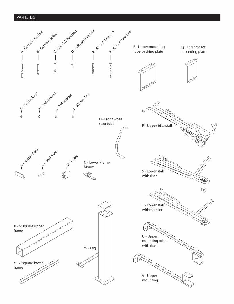
PARTS LIST
A - Cem
ent Anch
or
B - Cem
ent Spike
C -1/4
- 2.5 hex b
olt
D - 3/8
carri
age bolt
E - 3/8
x 3” hex b
olt
F - 3/8
x 4” hex b
olt
G - 1/4
lock
nut
H - 3/8
lock
nut
I - 1/4
wash
er
J - 3/8
wash
er
K - Space
r Plate
L - Ste
el Axe
l
M - R
oller
O - Front wheel stop tube
N - Lower Frame Mount
P - Upper mounting tube backing plate
Q - Leg bracket mounting plate
X - 6” square upper frame
Y - 2” square lower frame
W - Leg
R - Upper bike stall
S - Lower stall with riser
T - Lower stall without riser
U - Upper mounting tube with riser
V - Upper mounting

STEP 1A - FOR MULTIPLE SECTIONS ONLY
1. For multiple sections measure to center of leg bracket for even clamping.
2. Place legs and install 6” square upper frame (X).
STEP 1B - FOR SINGLE SECTIONS ONLY
1. For single sections measure to ends of leg brackets for max clamping support.
2. Place ends and install 6” square upper frame (X).
A. ASSEMBLE RACK
MEASURE
MEASURE
X
X
W
W
X
W

1. Attach leg bracket backing plate (Q) as shown and align holes.
2. Install 3/8 carriage bolts (D) with 3/8 washer (J) and 3/8 lock nut (H).
3. With all leg bracket backing plates installed tighten bolts evenly to 16ft. lbs min.
STEP 2 - LEG BRACKET ASSEMBLY 1
2
3
Q
D
J
H

STEP 3 - LEG MOUNTING
1. Install lower frame mounting feet (N) to 2” square lower frame (Y).
2. Place on leg base plates and align holes.
3. Drill mounting holes using leg mounting plates as templete, mark hole location on concrete fl oor.
4. Move rack to the side and drill holes. OPTION 1 (6263) - Hammer drill 1/2” hole in cement base. OPTION 2 (6260) - Hammer drill 3/8” hole in cement base. Note: Refer to Anchor kit mounting sheet for additional information.
5. Clean holes of cement debris.
6. Move rack back in place and align all holes.
1
2
3
STEP 4 - CEMENT ANCHORS
1. Install cement anchors and tighten nuts evenly or hammer in cement spikes.
DRILL OUT MOUNTING HOLES USING BASE PLATES AS TEMPLETE
(6263) Temporary Mounting(A): Install cement anchors sleeves and tighten bolts to 10ft. lbs.
(6260) Permanent Mounting(B):Hammer in cement spikes.
OPTION 1
OPTION 2
A
B
N
Y
Y
N

STEP 5 - STALL ASSEMBLY
1. Refer to cover page for proper mounting distances and spacing.
2. Place lower stall with riser (S) in fi rst bike position and slide mounting bracket over 2” lower frame.
3. Install 1/4” mounting bolts (C) with 1/4” washer (I) and 1/4” locknut (G) tighten to 4 ft. lbs. (Note: Do not over tighten)
4. Repeat process with lower stall without riser (T).
5. Evenly space and stagger bike stalls along 2” lower frame.
C
G
I
T
S
T
S

1. Align upper mounting tubes (U & V) directly above lower stalls. IMPORTANT!! - Upper mounting tubes with and without rise MUST correspond to lower stalls with and without rise. Example: Part U must be located directly above part S. Part V must be located directly above part T.
2. Evenly space and stagger upper mounting tubes along 6” upper frame.
3. Attach upper mounting tube backing plates (P) as shown and align holes.
STEP 6 - UPPER MOUNT ASSEMBLY
U
V
P
T
S

4. Install 3/8” carriage bolts (D) facing down with 3/8” washer (J) and 3/8” locknut (H).
5. Tighten bolts evenly to 16 ft. lbs. minimum.
6. Align front wheel stop tube (O) and spacer plate (K) with holes on right side of upper mounting tube as shown. Install 3/8” x 4” bolt (F) with 3/8” lock nut (H).
7. Tighten to 16 ft. lbs. maximum. (Note: Do not over tighten or lock nut could crush tube)
STEP 7 - UPPER MOUNT ASSEMBLY CONT.
J
H
D
H
KO F
O

1. Slide steel axle (L) into roller (M) and evenly space ends.
2. Place upper bike stall (R) onto upper mounting tube.
3. Align lower mounting holes with roller and axel and install 3/8” x 3” bolt (E).
4. Tighten 3/8” lock nut (H) to 16 ft. lbs.
5. Repeat for remainder of upper bike stalls.
6. When installation is complete pull out upper bike stall to ensure smooth and free movement.
2
3
STEP 8 - UPPER BIKE STALL ASSEMBLY
1
LM
E
R
H
Saris Cycling Group Inc. 5253 Verona Road Madison WI 53711 800.783.7257 www.sarisparking.com 18003 12/07