17278736 paper ccna osi model
TRANSCRIPT
8/14/2019 17278736 Paper Ccna Osi Model
http://slidepdf.com/reader/full/17278736-paper-ccna-osi-model 1/31
CISCO CCNA Certification knowledge to pass the exam(Taken from the CISCO WEB site)
Knowledge of OSI Reference Model
(1) Identify and describe the functions of each of the seven layers of the OSIreference model.
Open Systems Interconnection (OSI)OSI consists of two environments; the OSI environment, which is made up of sevenlayers of OSI protocols and the local system environment, which is the end computer system. The reason for dividing the environment in this way was to avoid interfering withthe innovation of the design and implementation of computer systems. OSI facilitates avehicle to communicate between dissimilar or similar computer based systems. The localcomputer system environment has a closed operating system and performs its designedfunctions within these bounds. All application processes that do not require
communicating with other systems to complete its tasks, will provide, the end result without any problems. However when an application process needs to communicate withanother application process located in a remote system, both systems must become opento the OSI environment Many operations and concepts are involved in this process. Thereis interaction between peer entities within a layer and interaction between layers.
Important concepts to understand OSI Layering are:
• Each layer performs unique and specific task
•
A layer only has knowledge of its immediately adjacent layers
• A layer uses services of the layer below
• A layer performs functions and provides services to the layer above
• A layer service is independent of the implementation
The Application layer is unique among the seven layers in that, it has no layer above. Theapplication consists of ‘Service Elements’ that are incorporated within the application process when it needs to become a part of the OSI environment.
1

8/14/2019 17278736 Paper Ccna Osi Model
http://slidepdf.com/reader/full/17278736-paper-ccna-osi-model 2/31
CONCEPT OF A LAYER
Each layer contains a logical groupings of functions that provide specific services for facilitating a communication. A function, or a group of functions, making up a functional
unit is a logical entity that accepts one or more inputs (arguments) and produces a singleoutput (value) determined by the nature of the function. Functions can be grouped in acollective unit, which is then defined as (N) layer having (N+1) layer an upper layer boundary and (N-1) layer as a lower boundary. The N layer receives services from N-1layer and provides services to N+1 layer.
SEVEN LAYERS OF THE OSI MODEL AND THEIR FUNCTIONS
• Layer 7 is the APPLICATION layer: provides services directly to applications.
Responsible for identifying and establishing the availability of the intended partner,and required resources. It is also responsible for determining if there exist sufficient
communication resources to reach the remote partner.
• Layer 6 is the PRESENTATION layer: Data encryption, decryption, compression and
decompression are functions of this layer. It does this by using Abstract Syntax Notation 1 (ASN.1) ASN.1 standardization allows differing computer architectures toexchange data that are from differing computer architectures.
• Layer 5 is the SESSION layer: facilitates a dialog between communicating systems
and controls the dialog. Offers three different dialogs, simplex, half-duplex and fullduplex. Session is set up by connection establishment, data transfer and connection
release.
• Layer 4 is the TRANSPORT layer: Segments data and also reassembles data from
upper layers. Delivers data in a connection and connection less modes. Includessimplex (one way) half duplex (both ways one at a time) full duplex (both wayssimultaneously). Also flow control and error recovery.
• Layer 3 is the NETWORK layer: Establishes a connection between two nodes by
physical and logical addressing. Includes routing and relaying data throughinternetworks. This layer’s primary function is to deliver packets from the sourcenetwork to the destination network.
• Layer 2 is the DATA LINK layer: Ensures hardware addressing of the device, and
delivery to the correct device. Translates data messages from upper layers to frames,enabling hardware to transmit upper layer messages as a bit stream. Provides flowcontrol to the layer 2. Also carries a Frame Check Sequence to make sure the framereceived is identical to the one transmitted.
2
8/14/2019 17278736 Paper Ccna Osi Model
http://slidepdf.com/reader/full/17278736-paper-ccna-osi-model 3/31
• Logical Link Control (LLC) Sublayer of the Data Link Control layer
provides flexibility to Network Layer and the Media Access Control (MAC)layer. It runs between Network Layer and the MAC sublayer of the data Link
Layer.
• Media Access Control (MAC) Sub Layer of the Data Link Layer is
responsible for framing. It builds frames from the 1s and 0s that the PhysicalLayer picks up from the wire.
• Layer 1 is the PHYSICAL layer: Which transmits the raw bit stream and includes
electrical signaling and hardware interface.
(2) Describe connection orientated network service and connection less
network service. Identify the key difference between them.
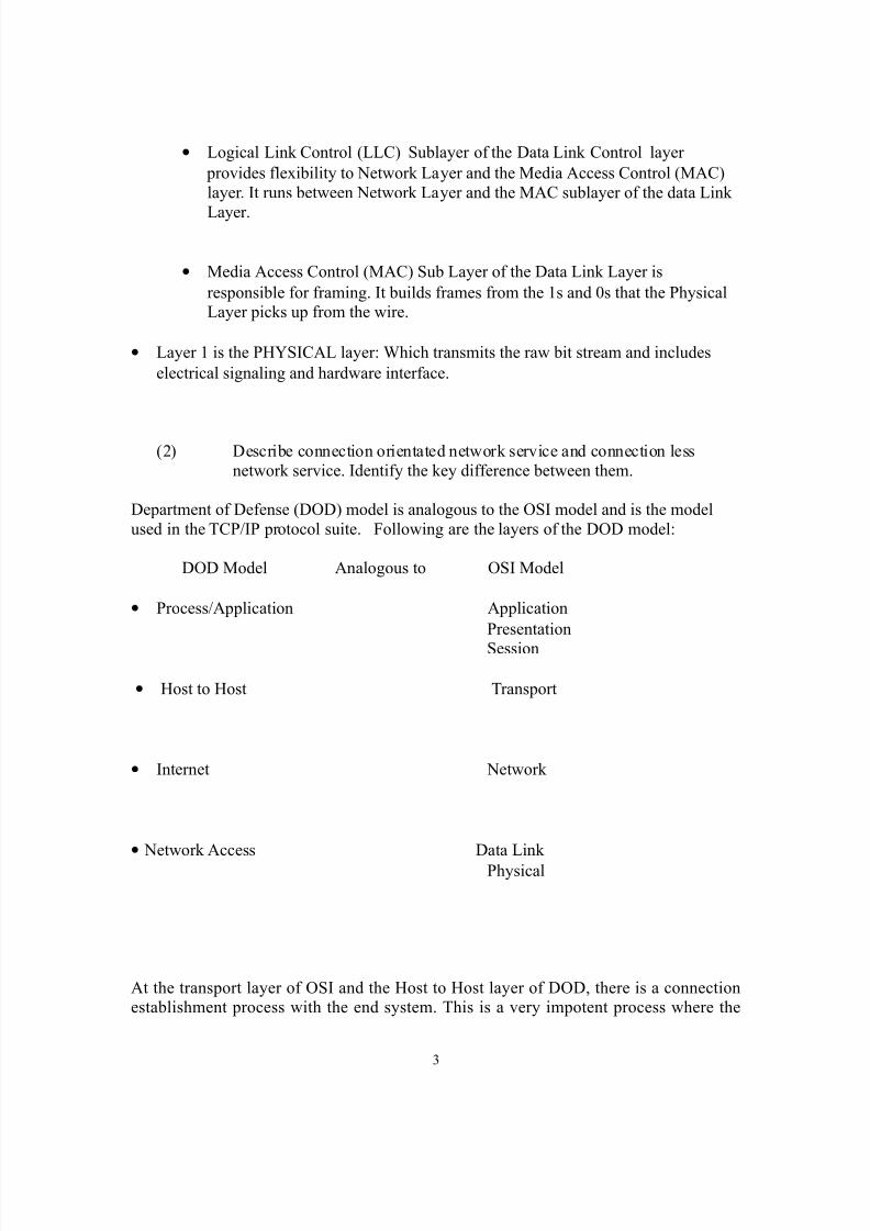
Department of Defense (DOD) model is analogous to the OSI model and is the modelused in the TCP/IP protocol suite. Following are the layers of the DOD model:
DOD Model Analogous to OSI Model
• Process/Application Application
Presentation
Session
• Host to Host Transport
• Internet Network
• Network Access Data Link
Physical
At the transport layer of OSI and the Host to Host layer of DOD, there is a connectionestablishment process with the end system. This is a very impotent process where the
3

8/14/2019 17278736 Paper Ccna Osi Model
http://slidepdf.com/reader/full/17278736-paper-ccna-osi-model 4/31
sending system decides whether to use a reliable link, which is connection orientated,resource intensive or to use an unreliable link, connection less access to the end systemwith very much less resource utilization.
The two protocols involved in the connection establishment of the end system is
Transmission Control Protocol (TCP) for reliable connection and User DatagramProtocol UDP for unreliable connection.
TCP is defined in the RFC 793 and defines a reliable, connection orientated full duplex byte stream for a user process. TCP creates a CONNECTION orientated service bycontacting the end system and establishing a set of guidelines both can support. Suchagreements as how much data segments can be transferred before an acknowledgement isreceived. TCP takes large blocks of data coming from upper layers and segments them.Then it adds numbers to the segments so the end system can sequence them at arrival andassemble the original block before sending it to the upper layer. When TCP creates aconnection between two end systems, it is called a VIRTUAL CIRCUIT. This virtual
circuit is created at the time the one system needs to send a data stream to the end systemand takes it down when the data transfer is completed.
The three phases of the TCP are CONNECTION ESTABLISHMENT, CONNECTIONMAINTENANCE and CONNECTION TIREDOWN.
UDP is defined in RFC 768. It is the protocol that does not consume system resources asmuch as TCP but it unreliable and transfers data to the destination system with outestablishing a connection and hence, connectionless protocol. UDP sends data to thedestination system in numbered segments same as TCP but it can not retransmit erredsegments if they get lost or damaged.
4
8/14/2019 17278736 Paper Ccna Osi Model
http://slidepdf.com/reader/full/17278736-paper-ccna-osi-model 5/31
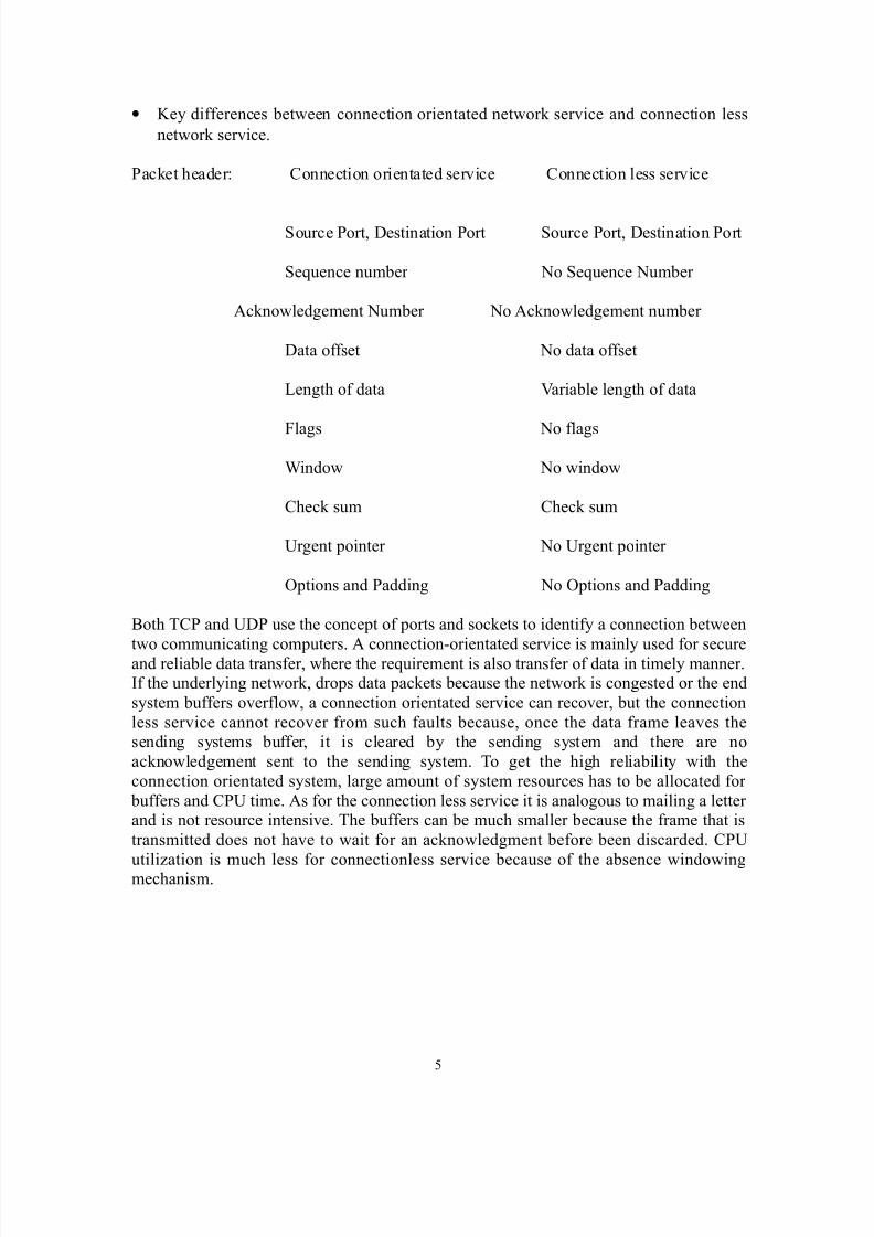
• Key differences between connection orientated network service and connection less
network service.
Packet header: Connection orientated service Connection less service
Source Port, Destination Port Source Port, Destination Port
Sequence number No Sequence Number
Acknowledgement Number No Acknowledgement number
Data offset No data offset
Length of data Variable length of data
Flags No flags
Window No window
Check sum Check sum
Urgent pointer No Urgent pointer
Options and Padding No Options and Padding
Both TCP and UDP use the concept of ports and sockets to identify a connection between
two communicating computers. A connection-orientated service is mainly used for secureand reliable data transfer, where the requirement is also transfer of data in timely manner.If the underlying network, drops data packets because the network is congested or the endsystem buffers overflow, a connection orientated service can recover, but the connectionless service cannot recover from such faults because, once the data frame leaves thesending systems buffer, it is cleared by the sending system and there are noacknowledgement sent to the sending system. To get the high reliability with theconnection orientated system, large amount of system resources has to be allocated for buffers and CPU time. As for the connection less service it is analogous to mailing a letter and is not resource intensive. The buffers can be much smaller because the frame that istransmitted does not have to wait for an acknowledgment before been discarded. CPU
utilization is much less for connectionless service because of the absence windowingmechanism.
5
8/14/2019 17278736 Paper Ccna Osi Model
http://slidepdf.com/reader/full/17278736-paper-ccna-osi-model 6/31
(3) Describe Data Link addresses and Network Address, and identify the keydifferences.
Data Link addresses are the source address and the destination address of the 48 bit BIAof the hardware NIC card. At each interface these addresses change because, on route to
the destination a frame has to pass may INC cards. Address Resolution Protocol (ARP)finds the MAC address when it moves to a different segment. Network layer address hasa source and a destination address, which are end points of the transmitting and receivingsystems. It provides routing and relaying functions to achieve it goal. It provides atransparent path to the transport layer for a best end to end packet delivery service.
(4) Identify at least three reasons why industry uses a layered model
Layered model avoids interfering with the innovation of design and implementation of computer systemsFacilitates communication between dissimilar systemsAllow changes to one layer with out changing other layersFacilitate systematic network trouble shootingReduce the complexity of networking into more manageable layers and sub layers
(5) Define and explain the five conversion steps of data encapculation
•
User information is converted to data• Data is converted to segments
• Segments are converted to packets or datagrams
• Packets or datagrams are converted to frames
•
• Frames are converted to bits (1s and 0s)
(6) Define Flow Control and describe the three basic methods used innetworkig
Flow control stops a sending station from flooding the receiver station buffers, if it has noresources to match the speed of data arriving from the receiving station. Once the buffersare emptied at the receiver, it sends a message to the transmitter to start sending again. Itis called windowing and controls how much data is transmitted from one end to the other.
Has a fixed window say 7, the transmitting station sends seven packets before waiting for an acknowledgement packet. Once the acknowledgement is received at the receiver, itsends another seven packets.
6
8/14/2019 17278736 Paper Ccna Osi Model
http://slidepdf.com/reader/full/17278736-paper-ccna-osi-model 7/31
Window size of one. Every packet sent to the receiver has to be acknowledged before thetransmitter can send the next packet.Variable window, if the receiving station for some reason finds difficult to catch up with buffer emptying, it then tells receiver to reduce the window size and the sender does so.
(6) List the key internetworking functions of the OSI network layer and howthey are performed in a router.
Network layer of the OSI seven layer model conations many protocols that a router useto evaluate the best route it should take and it is updated regularly so the best route isavailable for the packet to be transported. Network layers primary function is to send packets from the originating network to destination network. After the router has decidedthe best path from source to the destination network, the router switches the packet to it.This is known as packet switching. Essentially, this is forwarding the packet received bythe router on one network interface (NIC card), or port to the port that connects to the
best path through the network cloud. An internetwork must continually designate all paths of its media connections. All routers in the internetwork cloud are connected bymedia (cables), each line connecting a router to another is numbered. Routers use thesenumbers as network addresses. These addresses posses and convey important informationabout the path of the media connections. They are used by routing protocols to pass packets from a source onward towards to its destination. The network layer creates acomposite “network map” and a communication strategy model by combininginformation about the sets of links into an internetwork with path discrimination, pathswitching and route processing functions. It can also use these addresses to provide relaycapability and to interconnect independent networks. Routers using network layer protocols streamline network performance by not letting unnecessary broadcasts get intothe internetwok cloud.
Knowledge of WAN protocols
(8) Differentiate between the following WAN services: FRAME RELAY,ISDN/LAPD, HDLC and PPP
Frame relay is used to connect large number of sites in the network because it isrelatively inexpensive to do so. The service provider gives you a frame relay circuit andis charged for the amount of data and the bandwidth you use as oppose to T1 circuit thatcharges with a flat monthly rate whether you use partial bandwidth or the full bandwidthregardless. Frame relay is a high performance WAN protocol that operates at the DataLink layer and the Physical layer of the OSI model.
Integrated Services Digital Network (ISDN) is designed to run over existing telephonenetworks. It can deliver end to end digital service carrying voice and data. ISDN operatesat OSI model, physical layer, data link layer and network layer. It can carry multimediaand graphics with all other voice, data services. ISDN supports all upper layer protocols
7

8/14/2019 17278736 Paper Ccna Osi Model
http://slidepdf.com/reader/full/17278736-paper-ccna-osi-model 8/31
and you can choose PPP, HDLC or LAPD as your encapsulation protocol. It has twoofferings, Primary rate which is 23B+D channels. 23, 64 kbps and one 64kbps mainlyused for signaling. The other is the Basic Rate which has 2B+D channels two 64kbps andone 16kbps.
At data link layer ISDN supports two protocols; LAPB and LAPD. LAPB is used tomainly transfer data from upper layers and has three types of frames. I-Frames carryupper layer information and carries out sequencing, flow control, error detection andrecovery. S- Frames carry control information for the I-frame. LAPD provides anadditional multiplexing function to the upper layers enabling number of network entitiesto operate over a single physical access. Each individual link procedure actsindependently of others. The multiplex procedure combines and distributes the data link channels according to the address information of the frame. Each link is associated with aspecific Service Access Point (SAP), which is identified in the part of the address field.
High Level Data Link Control (HDLC) is a bit oriented data link layer frame protocol
that has many versions similar to LAP, LAPB, and LAPD. CISCO routers defaultencapsulation is HDLC, but it is proprietary to CISCO.
Point to Point Protocol (PPP) is a Data Link Layer protocol that can be used over ether asynchronous (dial up) or synchronous (ISDN) lines. It uses Link Control Protocol (LCP)to build and maintain data link connections. Included in PPP is the authentication protocols, PAP and CHAP, and data compression. It supports IP, IPX, AppleTalk, DECnetand OSI/CLNS.
(9) Recognize key Frame Relay terms and features
Frame Relay is a high performance WAN protocol that operates at the physical and datalink layer of the OSI reference model. It was originally designed to operate on ISDNcircuits, but today it is used on variety of network interfaces. To configure Frame Relayon a CISCO router, we have to specify it as an encapsulation on a serial interface. Thereare only two encapsulation methods are available, CISCO, the default and the type IETF.A frame Relay connection between CISCO devices the type: CISCO is used and betweena CISCO device and a non CISCO device type IETF is used.
#encapsulation frame relay cisco or #encapsulation frame relay ietf
Frame Relay virtual circuits are identified by Data Link Connection Identifiers (DLCI).DLCIs are issued by the Frame Relay service provider. It is used to map IP addresses ateach end of the virtual circuit. Local Management Interface (LMI) was developed byCISCO and others to enhance the CCITT-ITU standard with protocol features thatallowed internetworking devices communicate easily with a Frame Relay network. LMImessages provide current DLCI values, global or local significance of the DLCI valuesand the status of virtual circuits. CISCO supports three types of LMIs: CISCO which isthe default, ANSI and Q933A.
8
8/14/2019 17278736 Paper Ccna Osi Model
http://slidepdf.com/reader/full/17278736-paper-ccna-osi-model 9/31
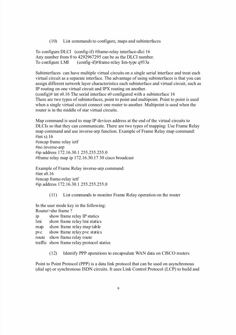
(10) List commands to configure, maps and subinterfaces
To configure DLCI (config-if) #frame-relay interface-dlci 16
Any number from 0 to 4292967295 can be as the DLCI number.To configure LMI (config-if)#frame-relay lim-type q933a
Subinterfaces can have multiple virtual circuits on a single serial interface and treat eachvirtual circuit as a separate interface. The advantage of using subinterfaces is that you canassign different network layer characteristics each subinterface and virtual circuit, such asIP routing on one virtual circuit and IPX routing on another.(config)# int s0.16 The serial interface s0 configured with a subinterface 16There are two types of subinterfaces, point to point and multipoint. Point to point is usedwhen a single virtual circuit connect one router to another. Multipoint is used when therouter is in the middle of star virtual circuits.
Map command is used to map IP devices address at the end of the virtual circuits toDLCIs so that they can communicate. There are two types of mapping: Use Frame Relaymap command and use inverse-arp function. Example of Frame Relay map command:#int s).16#encap frame relay ietf #no inverse-arp#ip address 172.16.30.1 255.255.255.0#frame relay map ip 172.16.30.17 30 cisco broadcast
Example of Frame Relay inverse-arp command:#int s0.16#encap frame-relay ietf #ip address 172.16.30.1 255.255.255.0
(11) List commands to monitor Frame Relay operation on the router
In the user mode key in the following:Router>sho frame ?ip show frame relay IP staticslmi show frame relay lmi staticsmap show frame relay map table pvc show frame relay pvc staticsroute show frame relay routetraffic show frame relay protocol statics
(12) Identify PPP operations to encapsulate WAN data on CISCO routers
Point to Point Protocol (PPP) is a data link protocol that can be used on asynchronous(dial up) or synchronous ISDN circuits. It uses Link Control Protocol (LCP) to build and
9

8/14/2019 17278736 Paper Ccna Osi Model
http://slidepdf.com/reader/full/17278736-paper-ccna-osi-model 10/31
maintain data link connections. Some features included in PPP are: PasswordAuthentication Protocol (PAP) and Challenge Handshake Password AuthenticationProtocol (CHAP). Data compression and multiprotocols such as IP, IPX , AppleTalk DECnet and OSI/CLNS are supported. Encapsulate PPP on the router #int s0
#encapsulate ppp
(13) State a relevant use and context for ISDN networking
Integrated Services Digital Network (ISDN) can run on existing telephones lines to provide an end to end digital service for both domestic and business uses. ISDN cancarry, in addition to voice and data, multimedia as well. ISDN can used as a backupcircuit for high speed network links. CISCO routers can be configured to automaticallydial up on an ISDN link when the main network link goes down.
(14) Identify ISDN protocols, function groups, reference points and channels
ISDN protocols were defined by CCITT (now ITU-T), and there are three protocols thatdefine the complex transmission issues:
• Protocol specifications beginning with latter E, specify ISDN on the existing
telephone network, ie; Analog lines.
• Protocol specifications beginning with letter I, specify concepts, terminology
and services.
• Protocol specifications beginning with letter Q, specify trunk switching and
signaling.
(15) Describe CISCO’s Implementation of ISDN BRI
ISDN Basic Rate Interface (BRI), service provides two B channels and D channel, whichis also known as 2B+D. B channels operate at 64 kbps and carries user information whereD channel operates at 16 kbps and usually carry control and signaling information. Dchannel signaling protocol spans the OSI reference model’s, Physical layer, Data link layer and the Network layer. The two 64 kbps lines can be used as a single 128 kbps
channel. To place a call on ISDN is similar to placing a call on Plain Old Telephones(POTS). For ISDN network to identify a call placed on its network, you must usedirectory numbers and Service Profile Identifiers (SPID)s. These two items are given toyou by the service provider. Directory number is a telephone number you will use whenyou call. The SPID is a number the telephone uses to identify equipment on your ISDNconnection. Majority of switches in US are either AT&T 5ESS, 4ESS or Northern TelcomDMS 100. Attaching a CISCO router to ISDN needs either a Network Termination 1 or
10

8/14/2019 17278736 Paper Ccna Osi Model
http://slidepdf.com/reader/full/17278736-paper-ccna-osi-model 11/31
an ISDN modem. If router has a BRI interface, (called Terminal End Point 1) then it isready to be connected to the ISDN network.
Router#config tRouter(config)#isdn switch-type basic-dms100
Router(config)#int bri0Router(config-if)#encap pppRouter(config-if)#isdn spid 775456721Router(config-if)#ppp authentication chap
IOS
(16) Log in to a router in user and privilege mode
CISCO IOS software has a command interpreter called Exec. Exec has two levels of access: User mode and privilege mode. These two levels serve as for access into the
different levels of commands. In user mode one can only do: Check router status,connecting to remote devices, making temporary changes to terminal settings andviewing basic system information. In the privilege mode you can change theconfiguration of the router and get detail reports of router status. Test and run debugoperations. Access global configuration modes.
When you first log into a router, press ENTER and you will be in the Exec mode. At the prompt it will ask if you need a password. Router> This is the User mode as stated abovevery little can be done at this level. When you type in Enable: Router>Enable and pressreturn it will ask for the password. Once you key in the correct password, your in the privilege mode. Now the prompt will show you Router#.
(17) Use the context-sensitive help facility
One can receive help on any command by typing ? after the command. In the followingexample: Router# clock ? you typed in clock a space and the question mark, and pressedenter. Reply was as follows: set Set the time and date. Now you want to know whatformat to enter. So you put another question after the set as follows: Router# clock set ?. Now you will get the format in the reply as follows: hh:mm:ss: Current Time (hh:mm:ss)
(18) Use the command history and editing features
The user interface comes in with an editing feature to help you type in repetitivecommands. One can turn off editing by typing terminal no editing and again turn it on by typing terminal editing.
The router keeps the last ten commands you entered during your console or terminalsession, in a special memory buffer called command history. One can recall commandsfrom the command history buffer and reuse them or modify slightly to save on typing. Tosee all the commands type the following at the command prompt Router#show history
11
8/14/2019 17278736 Paper Ccna Osi Model
http://slidepdf.com/reader/full/17278736-paper-ccna-osi-model 12/31
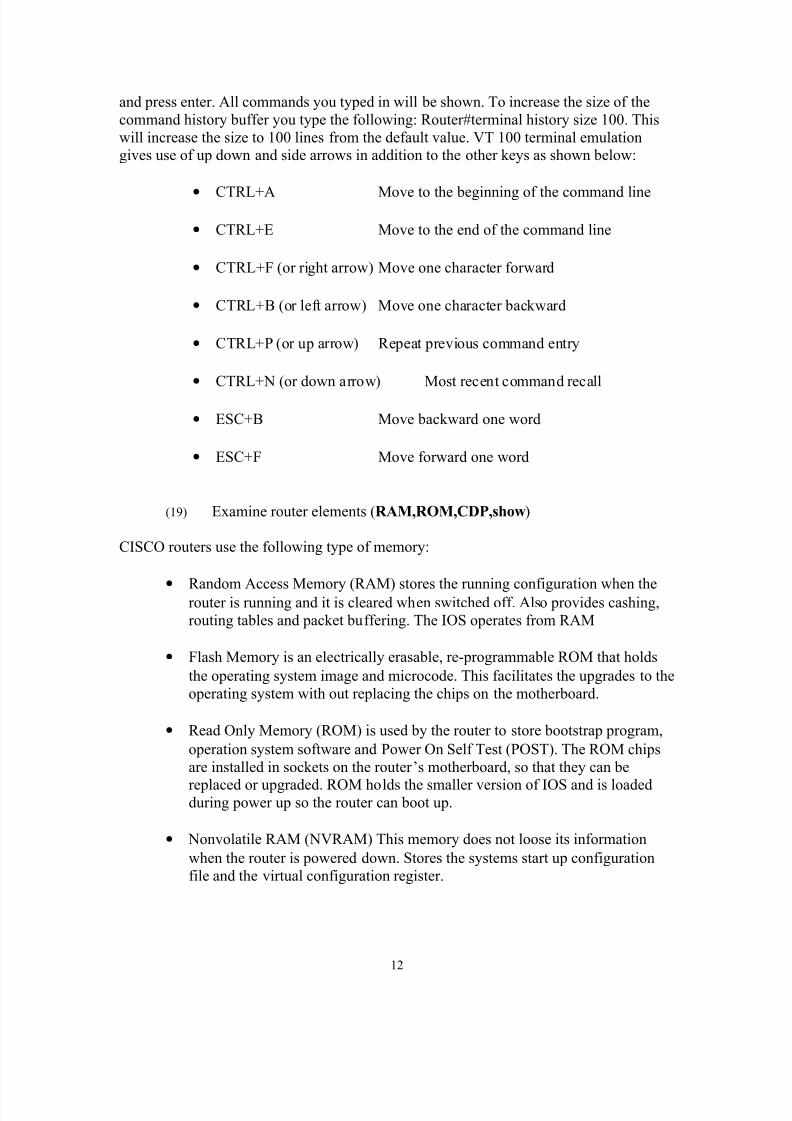
and press enter. All commands you typed in will be shown. To increase the size of thecommand history buffer you type the following: Router#terminal history size 100. Thiswill increase the size to 100 lines from the default value. VT 100 terminal emulationgives use of up down and side arrows in addition to the other keys as shown below:
•
CTRL+A Move to the beginning of the command line
• CTRL+E Move to the end of the command line
• CTRL+F (or right arrow) Move one character forward
• CTRL+B (or left arrow) Move one character backward
• CTRL+P (or up arrow) Repeat previous command entry
• CTRL+N (or down arrow) Most recent command recall
• ESC+B Move backward one word
• ESC+F Move forward one word
(19) Examine router elements (RAM,ROM,CDP,show)
CISCO routers use the following type of memory:
•
Random Access Memory (RAM) stores the running configuration when therouter is running and it is cleared when switched off. Also provides cashing,routing tables and packet buffering. The IOS operates from RAM
• Flash Memory is an electrically erasable, re-programmable ROM that holds
the operating system image and microcode. This facilitates the upgrades to theoperating system with out replacing the chips on the motherboard.
• Read Only Memory (ROM) is used by the router to store bootstrap program,
operation system software and Power On Self Test (POST). The ROM chipsare installed in sockets on the router’s motherboard, so that they can be
replaced or upgraded. ROM holds the smaller version of IOS and is loadedduring power up so the router can boot up.
• Nonvolatile RAM (NVRAM) This memory does not loose its information
when the router is powered down. Stores the systems start up configurationfile and the virtual configuration register.
12

8/14/2019 17278736 Paper Ccna Osi Model
http://slidepdf.com/reader/full/17278736-paper-ccna-osi-model 13/31
Cisco Discovery Protocol (CDP) is CISCO’s proprietary protocol that allows you toaccess configuration on other routers with a single command. By running Sub Network Access Protocol (SNAP) at the data link layer, two devices running different Network Layer protocols can communicate and learn about each other. These devices include allLAN and some WANs. CDP starts by default on any router version 1.3 earlier and
discovers neighboring CISCO routers running CDP by doing a Data Link broadcasts. Itdoes not matter what protocol is running at the network layer. Once CDP has disproved arouter, it can then display information about the upper layer protocols, such as IP andIPX. The router caches the information it receives from its CDP neighbors. Any time arouter receives up dated information that a CDP neighbor has changed, it discards the oldinformation in favor of the broadcast.
There are many show commands available for the administrator to manage the router.They can be found by typing at the command prompt Router#sh ?.
(20) Manage configuration files from the privilege exec mode.
When the router is powered up, it does a self-test, then a loads the IOS image, and findsthe configuration file and loads it. Startup configuration is in NVRAM and the operatingsystem places it on to the RAM. To manage configuration files you must be in privilegemode. At start up you will be in user mode. To get to the privilege mode do the following:Router>enable, if passwords are enabled then enter them when asked. Now your in privilege mode. Router#. By typing config t you can modify configuration files.Following are commands for starting and saving configurations:
•
Show startup-config Shows the configuration that will loaded when therouter boots.
• Show running-config Show the configuration that is currently loaded
to RAM and is running
• Erase startup-config This command will erase the configuration in
NVRAM and put you in to the initial configurationdialog
• Reload This command will reload the startup-config to
Memory
• Setup This command starts the initial configuration dialog
Software version 10.3 and earlier should run the following router commands:
• Show config Same as show startup-config
13
8/14/2019 17278736 Paper Ccna Osi Model
http://slidepdf.com/reader/full/17278736-paper-ccna-osi-model 14/31
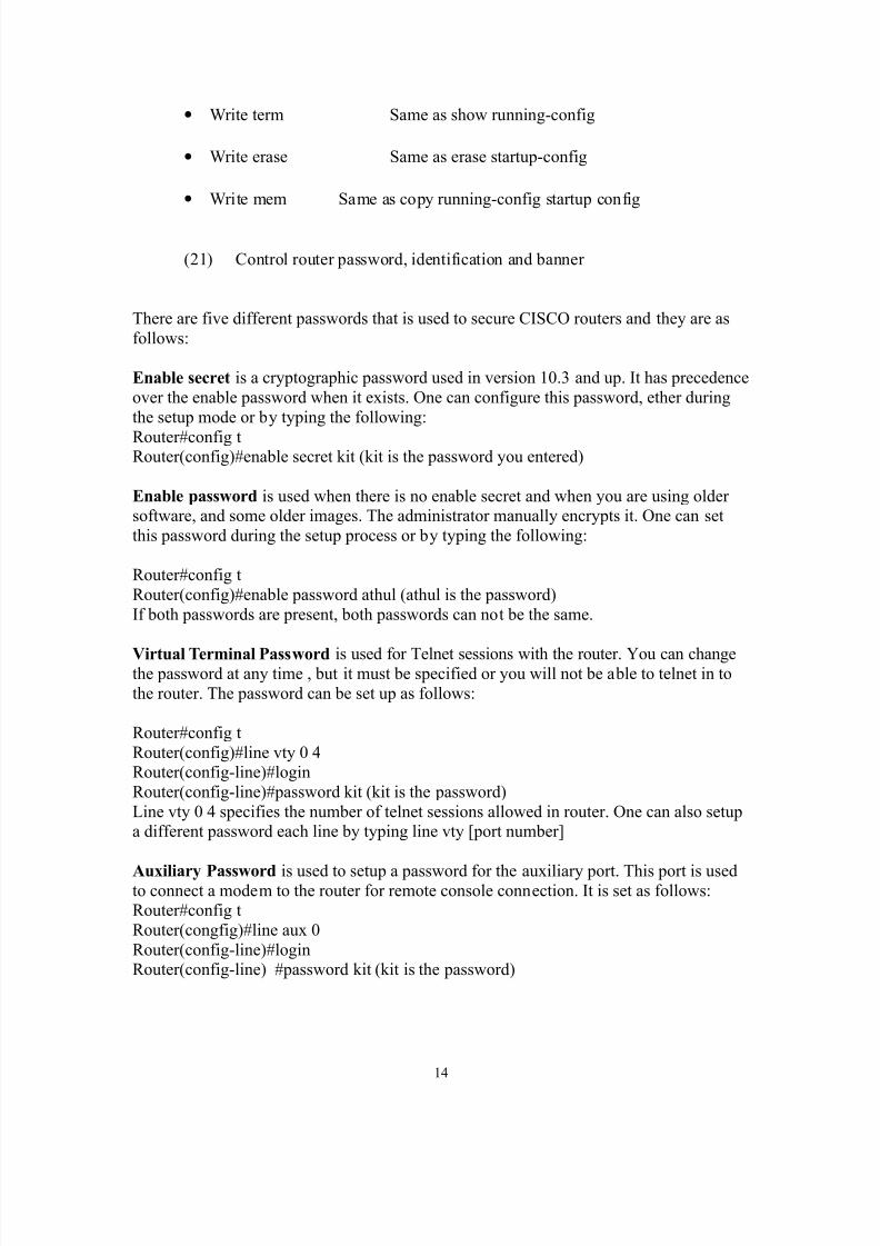
• Write term Same as show running-config
• Write erase Same as erase startup-config
• Write mem Same as copy running-config startup config
(21) Control router password, identification and banner
There are five different passwords that is used to secure CISCO routers and they are asfollows:
Enable secret is a cryptographic password used in version 10.3 and up. It has precedenceover the enable password when it exists. One can configure this password, ether duringthe setup mode or by typing the following:
Router#config tRouter(config)#enable secret kit (kit is the password you entered)
Enable password is used when there is no enable secret and when you are using older software, and some older images. The administrator manually encrypts it. One can setthis password during the setup process or by typing the following:
Router#config tRouter(config)#enable password athul (athul is the password)If both passwords are present, both passwords can not be the same.
Virtual Terminal Password is used for Telnet sessions with the router. You can changethe password at any time , but it must be specified or you will not be able to telnet in tothe router. The password can be set up as follows:
Router#config tRouter(config)#line vty 0 4Router(config-line)#loginRouter(config-line)#password kit (kit is the password)Line vty 0 4 specifies the number of telnet sessions allowed in router. One can also setupa different password each line by typing line vty [port number]
Auxiliary Password is used to setup a password for the auxiliary port. This port is usedto connect a modem to the router for remote console connection. It is set as follows:Router#config tRouter(congfig)#line aux 0Router(config-line)#loginRouter(config-line) #password kit (kit is the password)
14
8/14/2019 17278736 Paper Ccna Osi Model
http://slidepdf.com/reader/full/17278736-paper-ccna-osi-model 15/31
Console Password is used to setup a password for the console port. It can be set up asfollows:
Router#config tRouter(config)$line con 0
Router(config-line)#loginRouter(config-line)#password kit (kit is the password)
Entering a Banner
The banner added will be displayed when ever any one logs in to the CISCO router. Thecommand to enter is banner #.motd. Message of the day (motd) has to start with adelimiting character. Type as follows: Router(config)#banner motd k (k is the delimiter) Now enter the text message and end with the character ‘k’. So we enter the following: If you are not authorized log out immediatelyK(and press enter)Router(config)#end
(22) Identify the main CISCO IOS commands for router startup.
Router’s configuration files contain the configuration of the router. There are two basicconfiguration files for each router: startup and running. Startup configuration is held in NVRAM and is accessed when router is started. The startup configuration is placed inRAM for the router to run. Following command will display the startup configuration.Router#sh star
(23)Enter the initial configuration using the setup command
Setup command facility is an interactive facility that allows you to perform first timeconfiguration and other basic configuration procedure on the router. The command parser allows you to make detail changes to your configuration. However, some major configuration changes do not require granularity provided by the command parser. In thiscase you can use the setup command facility to make major enhancements to theconfiguration. Set up can make add a protocol suite, to make major addressing schemeschanges, or configure a newly installed interface. Setup command facility provides youwith a high level view of the configuration and guides you through the configurationchange process. If you are not familiar with CISCO products and the command parser,the setup command facility is a particularly valuable tool, because it asks you questionsrequired to make configuration changes. To start setup, key in the following:Router#setup and press enter.
15

8/14/2019 17278736 Paper Ccna Osi Model
http://slidepdf.com/reader/full/17278736-paper-ccna-osi-model 16/31
(24)Copy and manipulate configuration files
Binary executable IOS image is held in flash memory. IOS image is the binary programthat parses and executes the configuration, while IOS configuration tells the device itscurrent configuration. You can copy the content of the flash to a TFTP server by entering
the following command Router#copy flash tftpOne can copy TFTP server to flash memory by typing Router#copy tftp flash. Aninteractive dialog begins and asks whether to erase the entire content of the flash beforecopying the file. Content of the flash memory can be displayed by the commandRouter>sh flash
One can copy the current configuration from a router to a TFTP server by typingRouter#copy run tftp.
Or telnet to the router, copy a TFTP configuration file to running conflagration by typingthe following command: Router#copy run
(25)List the commands to load CISCO IOS software from: flash memory,TFTP server, or ROM.
One can specify where the router should look for the CISCO IOS software to create a fall back in case one configuration does not load or one needs to load from a TFTP server. Toload the CISCO IOS from a TFTP server, use the following command string:Boot system TFTP ios_filename TFTP_ipaddress. There are three places that the CISCOrouter can look for the a valid IOS: flash, TFTP server or ROM. Following commandswill load the IOS from flash and ROMRouter(config)#boot flashRouter(config)#boot rom
(26) Prepare to backup, upgrade and load a backup CISCO IOS image Use the TFTP server to backup the IOS image. Type the following command at thecommand prompt: Router(config) copy flash tftp. Flash memory can be used to upgradethe IOS without physically changing the EEPROM. To load a backup image can becarried out from TFTP server, flash and ROM. Typing the following command will causethe router to try the other alternatives if the flash configuration does not come up. boot system flash ios_filename boot system TFTP ios_filename boot system rom
(27)Prepare the initial configuration of your router and enable IP
When you power up the router, it does a POST and finds and loads the IOS image, theoperation system for the router. Before the router can function, as you want it to, it needsto finds its configuration and apply it. If the router does not find a configuration file and it
16

8/14/2019 17278736 Paper Ccna Osi Model
http://slidepdf.com/reader/full/17278736-paper-ccna-osi-model 17/31
is not configured to find one on the network, it will begin the setup dialog. The setup ismenu driven and all you have to do is to answer the questions. Setup dialog will let youget the router up and running with a very basic configuration. It will allow you to give ahost name, set both password and secret password, enable any network layer protocolsassign appropriate addresses to router interfaces and enable dynamic routing protocols.
Every CISCO router has a 16 bit configuration register, which is stored in a secialmemory location in NVRAM. This register controls number of functions and some of which are listed below:
• Force the system in to the bootstrap program
• Select a boot source and default boot file name
• Enable or disable the console Break function
• Set the console terminal baud rate
• Load operating software from ROM
• Enable booting from a TFTP server
The configuration register boot field is the portion of the configuration register thatdetermines whether the router loads an IOS image, and if so where to get it from. Theleast significant four bits, 0 through 3, make up the boot field. If the boot field is 0x0 (allfour bits set to zeros) then the router will enter ROM monitor mode. If the boot fieldvalue is set to 0x1 (binary 0001) the router will boot from the image in ROM. If the bootfield value is 0x2 through 0xF (binary 0000 through 1111) then the router will follow thenormal boot sequence and will look for the boot system commands in the configurationfile on the NVRAM.. Type Router# sh ver, will display the configuration register valuecurrently in effect and the value that will be used at the next reload. Display line in thediscussion is displayed on the screen is as follows:Configuration register is 0x142 (will be 0x102 at next reload)
You can place special commands in the router’s configuration file that will instruct itwhere to find the IOS image. If you do not specify a file name, the router will load thefirst valid file it finds in the flash memory. Following are the boot commands:
Router(config)#boot system flash Boots from flashRouter(config)#boot system tftp 172.16.1.150 Boots from a TFTP server with ip address172.16.1.150Router(config)#boot system ROM Boots from ROM (this is last resort if nothingworks and should be changed after the flash is corrected)
Network Protocols
(28) Monitor Novell IPX operation on the router
Once you have IPX configured and running, following show commands can be used toverify and track router is communicating correctly:Router#sh ipx servers.This command will show the content of the SAP table. Server name, IPX address, port, route, hops and interface.
17

8/14/2019 17278736 Paper Ccna Osi Model
http://slidepdf.com/reader/full/17278736-paper-ccna-osi-model 18/31
Router#sh ipx route This command will display the IPX routing table entries that therouter knows about. The router reports networks to which is connected to directly andalso the networks that it has learned since coming on line.
If you were to up parallel IPX paths between routers, by default, the CISCO routers willnot learn about these paths. The router will learn a single path to the destination anddiscard alternative parallel, equal cost paths. If you need more than one parallel path to adestination then the router has to be configured Router(config)#ipx maximum paths 2 (upto 512).
Router#sh ipx traffic. This command will display a summary of the number of IPX packets received and transmitted by the router. Summary will show IPX, RIP and SAPupdate packets.
Router#sh ipx int e0
The debug IPX command will display IPX packets as its running through your internetwork Router#debug ipx routing can have two commands, debug routing activity or debugrouting events. Since debug IPX command is CPU intensive, it should be switched off assoon as monitoring process is over as shown: Router#undebug ipx routing act
(29) Describe two parts of network addressing, then identify the parts inspecific protocol address examples.
The 32 bit structure of the IP address is comprised of a network address and host address. Number of bits assigned to each of these components varies with the address class.IP addressing is analogues to the address of a letter. Street address is analogues to thenetwork address and the house number is analogues to the host address. The concept of subnetting allows the network portion of the address to be subdivided in to number of logical sections; subnets. With subnetting the two part IP address becomes a three partaddress, a network address, subnetwork address and a host address.
In Class A address, the most significant bit of the first octet is set to 0 and first octet is setfor the network address, leaving 24 bits for the host address. This corresponds to possiblenetwork addresses of 0 to 127. The reserved values are 0 and 127, leaving 1 to 126 for network addressing in class A.
In Class B address, the most significant bit and one after it is set to 10 leaving 16 bits for the network address and 16 bits for the host address. This corresponds to possiblenetwork address of 128 to 191.
In Classes C address, the most significant bit and two bits after are set to 110 leaving 24 bits for network address and 8 bits for host address. This corresponds to possible network address of 192 to 223.
18
8/14/2019 17278736 Paper Ccna Osi Model
http://slidepdf.com/reader/full/17278736-paper-ccna-osi-model 19/31
Class D and Class E is not required for the CCNA examination.
(30) Create different classes of IP addresses (and subnetting)
For the subnet address scheme to work, every host on the network must know which partof the host address will be used as the subnet address. This is accomplished by assigninga subnet mask to each host. Following are the subnet masks for each Class
• Class A net.node.node.node default subnet mask 255.0.0.0
• Class B net.net.node.node default subnet mask 255.255.0.0
• Class C net.net,net,node default sunet mask 255.255.255.0
(31) Configure IP addresses
Following commands will configure the IP address for the Ethernet interface 0Router#config tRouter(config)#int e0Router(config-if)#ip address 172.16.50.10 255.255.255.0Router(config-if)#no shut
(32) Verify IP addresses
Router#sh ip int e0 will display the following:Ethernet0 is up, line protocol is up
Internet address is 172.16.50.10 255.255.255.0Broadcast address is 255.255.255.255Also many other interface details
(33) List required IPX addresses and encapsulation type
IPX performs functions at layer 3 and 4 of the OSI model. It controls the assignment of IPX addresses (software addressing) on individual nodes, governs packet delivery acrossnetworks, and make routing decisions based on information provided by routing protocols, RIP or NLS. IPX is a connectionless protocol and it does not require anacknowledgement from the destination node. To communicate with upper layer protocols,
IPX uses sockets. These are similar to TCP/IP ports, in that they are used to address,multiple independent applications running on the same machine.
Sequence Packet eXchange (SPX) is a connection-orientated protocol as oppose to IPX.Through it upper layers can be assured that the data was delivered from the source to thedestination. SPX works by creating virtual circuits or connections between machines,with each connection having a specific connection ID, included in the SPX header.
19

8/14/2019 17278736 Paper Ccna Osi Model
http://slidepdf.com/reader/full/17278736-paper-ccna-osi-model 20/31
Routing Information Protocol (RIP) is a distance vector routing protocol used to discover IPX routes through internetworks. It employs ticks (1/8 th of a second) and the hop count(number of routers between nodes) as metric for determine preferred routes.
Service Advertising Protocol (SAP) allows servers to advertise the services they provide
on the network. There are three types of SAP packets defined: Periodic updates, servicequires and service response.
Netware Link Services Protocol (NLSP) is an advanced link state routing protocol,intended to replace Novell RIP and SAP.
Netware Core Protocol (NCP) provides clients with server resources such as file access,security and printing.
IPX addressing is somewhat different from IP addressing. The administrator assigns the
network part of the address and the node part is automatically assigned. IPX address has80 bits or 10 bytes. It is divided in to network address, which is 4 bytes and the nodeaddress which is the remaining 6 bytes. An example of an IPX address is as follows:0000.7C80.0000.8609.33E9. The first 8 hex digits (0000.7C80) represents the network part of the address, next 8 hex digits (0000.8609) represents the node part of the addressand the last 4 hex digits (33E9) represents the socket.
Encapsulation or framing is the process of taking packets from upper layer protocols and building frames to transmit across the network. Encapsulation takes IPX datagarms fromLayer 3 and builds frames at layer 2 to transmit on one of the supported media.
Encapsulation on following media is as follows:
• Ethernet Cisco Keyword
Netware Frame: Ethernet_802.3 novell-ether (default Netware 3.11)
Ethernet_802.2 sap
Ethernet_II arpa
Ethernet_snap snap
• Token Ring
Netware Frame: Token-Ring sap (default)
Token-Ring_snap snap
20

8/14/2019 17278736 Paper Ccna Osi Model
http://slidepdf.com/reader/full/17278736-paper-ccna-osi-model 21/31
• FDDI
Netware Frame: fddi_snap snap (default)
Fddi_802.2 sap
Fddi_raw novell-fddi
(34) Enable the Novell IPX protocol and configure interfaces
First you enable IPX routing and after you enable IPX protocol on each interface asfollows:
Router(config)#ipx routingRouter(config)#int e0Router(config-in)#ipx network 2100
You can add multiple frame types to the same interfaces follows: using the old wayRouter(config)#int soRouter(config-in)#ipx netwok 3200 encap hdlc sec
Next is to use the current method:Router(config)#int e0.100
Router(config-subif)#ipx network 2300 sap
(35) Identify functions of the TCP/IP Transport layer
The Transport layer protocol equivalent to the layer in the DOD model is the Host to Host protocol. Its main purpose is to shield the upper layer applications from the complexitiesof the network. Transmission Control Protocol (TCP) and the User Datagram Protocol(UDP) operate at this layer. TCP is a connection-orientated protocol, which means that itfirst establishes a connection on a virtual circuit between source and destination, beforesending user data. UDP is a connection less protocol, which means the source is notconcerned whether the datagram it sent to the destination, did arrive there or not. TCP
and UDP both receive large chunks of data form the upper layers and they break themdown to manageable segments so that they can be transmitted to their destinations. Eachsegment is numbered so that at the destination they can be reassembled. Only TCP keepstract of this reassembly process, by requesting the missing segment from the source. If asegment is missing from a UDP transmission, the destination does not have a mechanismrequest it from the source. Therefore UDP is a unreliable protocol. TCP carries out error checking, and requests a retransmission, also through a windowing mechanism it controls
21

8/14/2019 17278736 Paper Ccna Osi Model
http://slidepdf.com/reader/full/17278736-paper-ccna-osi-model 22/31
the data flow so that receiver buffers are not flooded by the source. TCP is a full duplex,connection orientated, reliable and accurate protocol.
(36) Identify the functions of the TCP/IP network layer protocol.
At network layer, the TCP/IP protocol suit has the Internet Protocol (IP) in operation. Thefunction of IP includes, packet routing and providing a single network interface to theupper layers. The lower layers do not carry out any routing and routing occurs at the IPinternet layer. To route, IP looks at each packet’s IP address, then using a routing table itdecides where a packet is to be sent next, choosing the best path. All hosts on a network has an IP address and it contains the required routing information to enabling the packetto travel to the destination. IP receive data segments from the next upper layer, which isthe Host to Host layer and fragments them to datagrams or packets. Each datagram isassigned an IP address of the sender and the IP address of the recipient. Each machinethat receives the datagram makes a routing decision based upon the packet’s destination
IP address. The IP packet has a header and in it there is a field which carries an IP typenumber. This number indicate the socket number that the IP datagram should use to passthe data to upper layer which is the Host to Host layer. Data travelling on the internetlayer is, either a TCP datagrma or a UDP datagram.
(37) Identify Functions performed by ICMP
Internet Control Message Protocol (ICMP)is a management protocol and a messagingservice provider for IP. Its messages are carried as IP datagrams. RFC 1256 ICMP Router Discovery Messages is an annex to ICMP, which affords hosts extend capability indiscovering routes to gateways. Periodically, router advertisements are announced over the network, reporting IP addresses for its network interfaces. Hosts listens for thesenetwork infomercials to acquire route information. A router solicitation is a request for immediate advertisement and may be sent by a host when it starts up. Following are somecommon events and messages that ICMP relates to:
• Destination Unreachable: If a router cannot send an IP address any further, it
uses ICMP to send a message back to the sender advertising it of thesituation. For example if the router receives a packet destined to a network that the router does not know about, it will send an ICMP DestinationUnreachable message back to the sending station.
• Buffer full: If a router’s memory buffer for receiving in coming datagrams is
full, it will use ICMP to send out this message.
• Hops: Each IP datagram is allotted a certain number of routers that it may go
through, called Hops. If it reaches its limit of hops before arriving at itsdestination, the last router to receive that datagram deletes it. The executioner
22

8/14/2019 17278736 Paper Ccna Osi Model
http://slidepdf.com/reader/full/17278736-paper-ccna-osi-model 23/31
router then uses ICMP to send an message to the originator that the datagramis dead.
• Ping: Packet Internet Groper uses ICMP echo message to check the physical
connectivity of machines on an internetwork.
(38) Configure IPX access lists and SAP filters to control basic Novell traffic
Similar to IP access lists IPX has two types of access lists: Standard IPX Access Lists andExtended IPX Access lists.
Standard IPX access lists allow or deny packets based on source and destination IPXaddresses. Template to enter standard IPX access lists is as follows:
Access-list (number from 800 to 899) (permit or deny) (source network IPX number)
(destination network IPX number)
Following example will show how the access list will permit or deny access to IPX packets.
Router#config tRouter(config)#access-list 810 permit 30 10Router(config)#int e0Router(config-if)#ipx access-group 810 out
810 correspond to the 800 to 899 range. This access-list mean that any network other than
30 will be denied access network 10. If we wanted to allow access all networks to 10other than 50 the access-list entry will be as follows:Router(config)#access-list 810 deny 50 10Once we configure the access-list we must apply it to the interface, and it applied asfollows:Router(config)#int e0Router(config-if)#ipx access-group 810 outWhich means that the above restriction is applied to the interface Ethernet 0, IPXoutgoing packets from the router to the network.
Extended IPX access lists can filter based on the following: Source network, source node,
destination network, destination node, IPX protocol (SAP, SPX etc) and IPX sockets.
Template to enter the extended IPX access list is as follows:access-list (number, 900 to 999) permit or deny (protocol) (source IPX network number)(source socket) (destination IPX network number) (destination socket)
Following example will show how the extended access list will permit or deny IPXnetwork access using extended access lists
23

8/14/2019 17278736 Paper Ccna Osi Model
http://slidepdf.com/reader/full/17278736-paper-ccna-osi-model 24/31
Router(config)#access-list 910 deny –1 50 0 10 0
This means that the access is denied to any IPX protocol type from IPX network 50 on allsockets to enter IPX network 10 on all sockets.If you want to let any network access any network, any protocol and on any socket the
entry will be as follows:
Router(config)#access-list 910 permit –1 –1 0 –1 0Again once the access list is configured it has to be applied the interface as follows:Router(config)int e0Router(config-if)#access-group 910 out
IPX SAP filters are used to control access IPX devices. The template for implementingIPX SAP filters are as follows: access-list (number 1000 to 1099) (permit or deny)(source network.node address of the server) (service type)
Source address here is the IXP internal address for example 0000.7c80.0000.8609.33e9Router(config)#access-list 1010 permit 0000.7c80.0000.33e9 0Access list 1010 is in the range, 1000 to 1099 reserved for IPX SAP filters. This IPX SAPfilter will allow packets from 0000.7c80.0000.8609.33e9 to enter the Ethernet interfaceand be included in SAP updates across the network. The last entry is the service type andwe entered 0, which means all services should be allowed.
Now that we created the SAP filter, lets apply it to the interface for it to be operational.We apply it to the interface as follows:Router(config)#int e0Router(config-if)#ipx input–sap-filter 1010
Routing
(39) Add the RIP routing protocol to your configuration
Route Information Protocol (RIP) is a distance vector routing protocol that practicesclassfull routing, which is used to discover the cost of a given route in terms of hops andstores that information on a routing table.
The router can then consult the table to select the least costly most efficient route to adestination. It gathers information by watching for routing table broadcasts by other routers and updating its own table in the event that a change occurs. RIP routing tableshas following minimum entries: IP destination address, A metric (1 to 15) indicative of the total cost in hops, of a particular route to a destination, IP address of a the next router that a datagram would reach , on the path to its destination, A maker signaling recentchanges to a route, Timers, which are used to regulate performance, Flags, which indicatewhether the information about the routers has recently changed, Hold-downs used to prevent regular update messages from reinstating a route that is no longer functional,
24

8/14/2019 17278736 Paper Ccna Osi Model
http://slidepdf.com/reader/full/17278736-paper-ccna-osi-model 25/31
Split horizon used to prevent routing loops. A poison reverse updates used to preventrouting loops. RIP sends out routing updates at regular intervals and whenever a network topology changes occurs. And uses the following timers to regulate its performance.
Routing table update timer typically 30 seconds
Route invalid timer 90 secondsRoute flush timer 240 secondsTo add RIP routing to a router type in the following:Router#config t
Router(config)#router ripRouter(config-router)#network 172.16.0.0Router(config-router)#^ZRouter#wr mem (write to the running configration)
(40) Add the IGRP routing protocol to your configuration
Interior Gateway Routing Protocol (IGRP) is a CISCO proprietary, distance vector interior routing protocol that was designed by CISCO to overcome the limitations presented by RIP. IGRP hop count is 255 as oppose to RIP’s limited 15 hop count.
IGRP advertises three types of routes:Interior: These are routes between subnets. If a network is not subnetted then IGRP willnot advertise the interior routes.
System: These are routes to networks within an Autonomous System. They are derivedfrom directly connected interfaces, other IGRP routes, or access servers. They do notinclude subnet information.
Exterior: These are routes to networks out side of the Autonomous System. They areconsidered when identifying a gateway of last resort. The gateway of last resort is chosenfrom the list of exterior routes that IGRP provides.
Type in the following to add IGRP routingRouter(config)#router igrp 10 (10 is the Autonomous System number it can be anynumber from 1 to 65535)Router(config-router)#network 172.16.0.0Router(config-router)#^ZRouter#wt mem
(41) Explain the services of separate and integrated multiprotocol routing
A separate protocol routing is when the routing device, eg: a switch uses a routing table based on MAC address, and can accommodate only one encapsulation type. This type of routing is carried out at the data link, MAC sublayer.
25

8/14/2019 17278736 Paper Ccna Osi Model
http://slidepdf.com/reader/full/17278736-paper-ccna-osi-model 26/31
Multiprotocol routing is carried out mostly by routers and similar devices because, therouting decisions are made at network layer and the routing tables are at network layer. Atnetwork layer there can exist, many different protocols and with them comes their ownassociated routing tables. So a router can have a IP routing table, IPX routing table and aApple Talk routing table.
A bridge or a switch connects two or more physical networks into a single logicalnetwork, where as routers connects two or more logical networks and routes betweenthem using information that is built by routing protocols and kept in routing tables. Theadvantage of a router as compared to a bridge or a switch is that it physically andlogically breaks a network in to multiple manageable pieces, allows for control of routed packets, and routes network layer protocols at the same time.
(42) List problems that each routing type encounters when dealing withtopology changes and describe techniques to reduce the number of these problems.
(43) Describe the benefits of network segmentation with routers
Routers filter by both the hardware and network addresses. Routers only forward packetsto the network segment that the packet is destined for. The benefits of network segmentation could be summarized as follows:
Manageability: Multiple routing protocols give the flexibility of designing for optimumrequirements of the network.
Increased functionality: CISCO routers addresses the issues of flow control, error controlcongestion control and fragmentation, Also efficient control over packet lifetime.
Multiple active paths: Using the protocols DSAPs, SSAPs and path metrics, routers canmake informed routing decisions as well as interpret the next layer protocol. CISCOrouters can have more than on active link between routers.
Network Security
(44) Configure standard and extended access lists to filter IP
Access lists are used to control access via a router to the network or from the network toanother network or to a device attached to the router. Packet filtering is performed by theaccess lists, to either, entering packets to the router, or exiting packets from the router.Apart from providing security to the network, access lists provide valuable static on packet flow.
26

8/14/2019 17278736 Paper Ccna Osi Model
http://slidepdf.com/reader/full/17278736-paper-ccna-osi-model 27/31
8/14/2019 17278736 Paper Ccna Osi Model
http://slidepdf.com/reader/full/17278736-paper-ccna-osi-model 28/31
Congestion begins to creep in and the user access to the network begins to slow down.The remedy for this situation is to segment the LAN in to manageable parts so that each part or segment has a amount of users attached to it so that it will get congested even if all the users access simultaneously. There are many ways to do this segmentation.
(47) Describe LAN segmentation using Bridges
Physical segmentation: You can segment by bridges and routers. Bridges segment at theMAC address of the Data Link layer. A bridge will first look at a routing table and matchthe packet to a segment and forwards it.
(48) Describe LAN segmentation using Routers
Routers use the network layer to segment the network with network layer address andthe MAC address of the interface. The routing table will give the MAC address and thenetwork layer addressing protocol address. eg IP address, IPX address or apple Talk
address.
(49) Describe LAN segmentation using Switches
LAN switches uses at line speed by using the destination MAC address. In order toensure that the packet is forwarded to the correct port, cut through switching is used. Cutthrough looks at the in coming frame FCS has passed it as error free, it looks at thedestination MAC address and starts to forward before the full packet is received. Cutthrough switching greatly improves the throughput.
(50) Name and describe two switching methods
The two switching methods or modes are Store and Forward, and Cut Through.
With Store and Forward switching method, the LAN router copies the entire frame in toits buffer and checks the following and discards the frame if they are not correct:A CRC error, if the frame is runt (less than 64 bytes including the CRC) or a giant (morethan 1518 bytes including CRC). The frame has no errors then the router looks up therouting table and sends to the correct interface for transmission down the line. Latencydue to this error checking varies with the length of the frame.
Cut Through switching, the LAN switch copies only the destination address to its buffers(six bytes after the preamble). It then looks at the destination address on the switchingtable, determines the outgoing interface and submits it to the correct interface for transmission down the line. Cut through switching reduce latency because, first it doesnot copy the complete frame to the buffer and secondly it starts to transmitting the frameas soon as it locate the destination address from the routing table.
28

8/14/2019 17278736 Paper Ccna Osi Model
http://slidepdf.com/reader/full/17278736-paper-ccna-osi-model 29/31
(51) Describe full and half duplex Ethernet operation
Full duplex can transmit and receive simultaneously, but to do so one needs a CISCOswitch that has a full duplex interface. The end user needs a full duplex NIC card so thatit can be connected to the switch full duplex switch interface. Full duplex Ethernet uses
point to point connections and it is collusion free transmission. This is because it does notshare bandwidth with any other device. The frames sent by two nodes can not collide because they are on physically separate transmit and receive circuits. If you have a fullduplex 10 Mbps Ethernet operating on the same switch port it can theoretically have athroughput of 20 Mbps.
Half duplex will send and receive, one at a time. When the transmitter is transmitting hisreceiving circuit is in active. Same with the receiver, when his receiving circuit is activehis transmitting circuit is inactive.
(52) Describe the congestion problem in Ethernetworks
Ethernet device gets access to the network by listening to the signals on the cable. If noone is transmitting then the device starts to transmit. If two devices start to transmit at thesame time a collusion will occur and each station will back off and retransmit the framelater. This is good for a small number of devices attached to the network but when thereare too many devices gets attached, the collisions become more frequent and delaysoccur.
(53) Describe the benefits of network segmentation with bridges
Bridges segment the network by the MAC address of the data link layer. By segmenting alogical network in to multiple physical segments, it ensures network reliability,availability, scalability and manageability.
(54) Describe the benefits of network segmentation with switches.
Just like bridges LAN switches use destination MAC address in order to ensure that the packet gets to the right out going port. Switches are similar to bridges with more portsattached to it.
(55) Describe the features and benefits of fast Ethernet
Fast Ethernet is the IEEE 802.3u standard also known as 100 Base T. It is 10 times faster because the bit rate is 100 Mbps instead of 10 Mbps for 10 Base T. This standard definesthe physical layer and the data link layer, and uses the same CSMA/CD transmissiontechnology as 10 Base T. The other standards associated with Fast Ethernet are as
29

8/14/2019 17278736 Paper Ccna Osi Model
http://slidepdf.com/reader/full/17278736-paper-ccna-osi-model 30/31
follows: 100 Base FX which is 100 Mbps two strand multi mode 50/125 or 62.5/125-micron fiber optic cable. 100 Base T4 can use CAT 3,4,or 5 cabling with RJ 45 connector.100 Base TX can use CAT 5 or 100 ohm two pair shielded twisted pair or type 1 cable.
Benefits of fast Ethernet can listed as follows:
• 100 Base T is 10 times faster as 10 Base T
• Existing cabling and network equipment can be used
• 10 Mbps and 100 Mbps can exist on the same cable media
• It uses tried and tested CSMA/CD
• Migration to 100 Mbps from 10 Mbps does not create any problems
(56) Describe the guide lines and distance limitations of Fast Ethernet
To exist on the same cable media, 10 Base T and 100 Base T, the time slots should be thesame. Standard defined round trip is shorter for 100 Base T. Therefore maximum distance between transmitter and receiver is shorter for 100 Base T. Maximum distance betweenend nodes for 100 Base TX is 100 meters and for 100 Base FX is 412 meters
(57) Distinguish between Cut Through and Store and Forward LAN switching
Cut through switching, the LAN switching device copies destination address to its in put buffer and looks at the destination switching table for the destination address. As soon asit finds the destination address, it starts to transmit the frame to the destination. Thisreducers the latency associated with store and forward
Store and forward switching, the LAN switching device copies the entire frame to its in put buffer and does a CRC check, runt check and a giant check on the frame. If any of them checks gives errors then the frame is dropped, if not it looks at the routing table andlocates the destination address and sends the frame to the appropriate interface to transmit
it down the line. All these checks take time and latency time increases for store andforward switching.
(58) Describe the operation of Spanning Tree Protocol and its benefits
IEEE 802.1d standard defines the Spanning Tree Protocol and was developed to preventrouting loops in a network. If a router, a switch or a hub has more than one path to the
30
8/14/2019 17278736 Paper Ccna Osi Model
http://slidepdf.com/reader/full/17278736-paper-ccna-osi-model 31/31
same destination, then a routing loop problem could occur. To prevent this, the spanningtree protocol is executed between devices to detect and logically block redundant pathson the network. For fault networks there should be redundant links between devices, andto be loop free it should also execute the spanning tree protocol.
(59) Describe the benefits of virtual LANs
Virtual LAN (VLAN) is a logical group of end users and resources connected to defined ports on a switch. This logical group communicates at layer 2 and layer 3 to establish theVirtual LAN. Most beneficial asset in implementing is the functional group. It is secure because on out side of the VLAN group can get access to the group and the members of the group can not go out side of the group. Next item is that if a member of the VLANgroup is moved from one floor to another, no set ups are required because the member can go to the next floor be connected to a different switch with a port that is in the sameVLAN group. Because VLAN operates at layer 2 and 3, broadcasts can be controlled.
Following are the primary benefits of VLAN: Broadcast control, Functional groups andSecurity.
(60) Define and describe the function of the MAC address
Media Access Control (MAC) address is the hardware address of the interface and it is burned in to the NIC card. This is a unique number issued by IEEE to the manufacturer. Itis 6 bytes long and the first 24 bits represents the vendor and next 24 bits represents theserial number of the NIC card. This hardware address is used by the MAC layer of theData Link layer to identify uniquely, the LAN device, to the network layer.