17 kv 45ma solid state jacobs ladder kit instructionsphysicsplayground.com/vdg instructions/jacobs...
TRANSCRIPT

17 KV 45MA Solid State Jacobs Ladder
Kit Instructions
by
Physics Playground
www.physicsplayground.com

17KV Jacobs Ladder Kit Instructions
www.physicsplayground.com frederickgraff©2012 Page 2
WARNING: Jacobs Ladders are high voltage devices that may be
lethal if touched and produce very high levels of ozone and
nitrogen oxides which are both toxic gases. These kits are built
and operated at your own risk and should only be assembled and
used by those who are familiar with constructing and operating
high voltage equipment. Once again, use at your own risk.
Jacob’s Ladder Introduction:
Thanks you and welcome to
what might be your first Jacobs
Ladder and from my experience, this
package contains the best
combination for building a compact
high output Jacobs Ladder by utilizing
solid state electronics along with a
very simplistic flow design that will
insure consistent convection currents
plus reduce the buildup of ozone and
nitrogen oxides that commonly taint
the arcing rod tube.
The operation of a Jacob’s
ladder is rather simplistic in its nature
such that it takes two conductive rods
and runs a high voltage across them
to achieve an arc at the location of
the least electrical resistance, which
is at the bottom where the rods are
the closest. The rising of the arcs is
created by the high temperature arcs
that induce a hot rising convection
current, causing the arc to rise along
with it. For the ladder to work
efficiently, the arc must be strong
enough to produce significantly hot

17KV Jacobs Ladder Kit Instructions
www.physicsplayground.com frederickgraff©2012 Page 3
convection currents. While most
ladders operate at 10KV, this unit will
run at 17 kV and pushes 30% more
current then the traditional NST
driven systems. You will find this
combination to produce very bright
fast rising arcs, however at the same
time the high power output will also
produce very high levels of ozone and
nitrogen oxides which cause an
orange tint build within the tube plus
are highly toxic materials, so always
use these in well ventilated areas
under constant supervisions or at
best, only use the ladder outdoors.
To prevent the buildup of these
toxic gases within the tube, you will
see that a fan has been designed into
the system that blows air through a
1/8 hole directly below the bottom of
the arcing rods. This hole ultimately
serves two purposes, the first being
to flush out the toxic gases and
secondly it will aid to the rising
convection currents, meaning that
the arcs will never get stuck.
With these concepts in mind,
let’s get ready to build the Jacobs
Ladder. To complete this ladder, you
will need the tools and materials
listed below and the overall build
process should only take about 1
hour to complete at a moderate
pace. Take your time and carefully
read through the instructions. Should
there be any questions along the way
please do not hesitate to contact me,
Frederick Graff the owner of Physics
Playground at
[email protected] or (209)
914-2619.
Tool and Supplies Needed
Screw Driver
(standard and
Phillips)
Flat Jaw Pliers
Small Vice Press
Box Knife
Electrical Tape
Drill with 1/8 and
3/16 bit
17KV Jacobs Ladder Kit Instructions
Frederick W. Graff©2012 Site Pass: highvoltage Password: john316
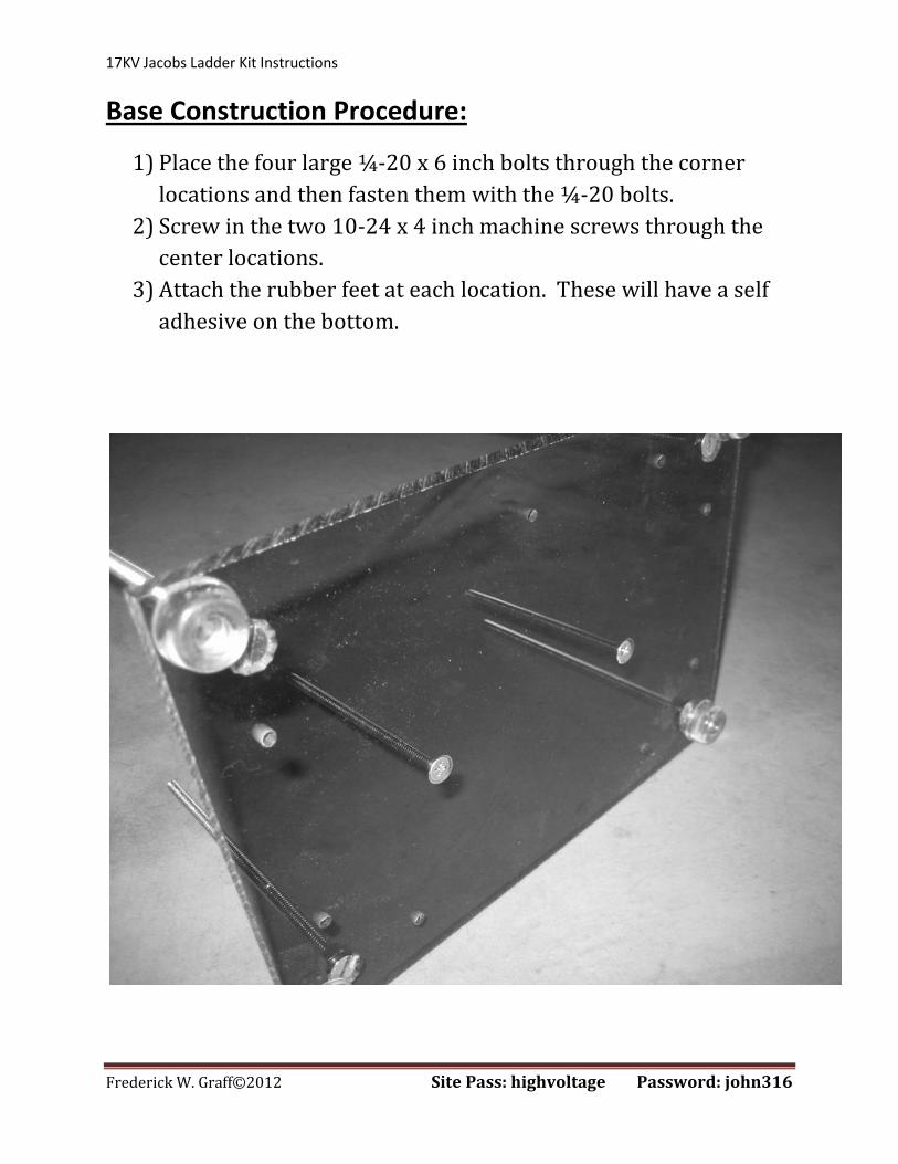
Base Construction Procedure:
1) Place the four large ¼-20 x 6 inch bolts through the corner
locations and then fasten them with the ¼-20 bolts.
2) Screw in the two 10-24 x 4 inch machine screws through the
center locations.
3) Attach the rubber feet at each location. These will have a self
adhesive on the bottom.

17KV Jacobs Ladder Kit Instructions
Frederick W. Graff©2012 Site Pass: highvoltage Password: john316
4) Connect the 6 L-Brackets the side locations and fasten the with
the smaller 10-24 x 3/8 machine screws.
5) Connect the acrylic sides at the L-Bracket location using the
10-24 x 5/8 machine screws along with the 10-24 wing nuts.
6) Place in the appropriate acrylic tubes at the following locations
as seen in the next illustration.
7) Attach the transformer mounting bracket and connect it with the
10-24 wing nuts.
8) Attach the transformer with the smaller screws that will be
located with the rod braces in a smaller bag. These screws look
like small wood screws. Because the transformer is very light,
only slightly snug the screws that hold the transformer to the
aluminum mount.

17KV Jacobs Ladder Kit Instructions
Frederick W. Graff©2012 Site Pass: highvoltage Password: john316

17KV Jacobs Ladder Kit Instructions
Frederick W. Graff©2012 Site Pass: highvoltage Password: john316
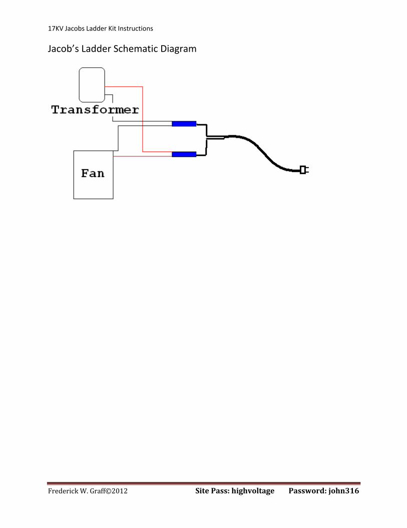
Wiring the circuit:
1) The fan and the transformer are wired in parallel with each other
and will turn on simultaneously.
2) Connect one of the wires from the transformer to one of the
wires from the fan and crimp both of them together on the same
side using the blue wire connector. Do the same with the wires
with another blue crimp terminal. Next, connect the other end of
the crimp terminals to the power cord. Make sure that there is no
wire exposed in the design.
17KV Jacobs Ladder Kit Instructions
Frederick W. Graff©2012 Site Pass: highvoltage Password: john316
Jacob’s Ladder Schematic Diagram

17KV Jacobs Ladder Kit Instructions
Frederick W. Graff©2012 Site Pass: highvoltage Password: john316
3) Fasten the fan using the 10-24 x ½ machine screw by inserting it
from the bottom of the base. Only snug the screw. You may need
to use a few small washers so that the screw does not interfere
with the fan blade.
4) Next, attach the small aluminum wire brace to hold the power
cord and situate the wires so that they are not touching the
transformer aluminum support brace and nor motor fan. Four
black zip ties have been included. If needed, use one of these to
brace the wires, just know that they must be kept distant from
the output wires from the transformer and its support because
they will short out.

17KV Jacobs Ladder Kit Instructions
Frederick W. Graff©2012 Site Pass: highvoltage Password: john316

17KV Jacobs Ladder Kit Instructions
Frederick W. Graff©2012 Site Pass: highvoltage Password: john316
Arcing Rods and Tubing:
1) Connect the bottom of the tubing base to the top plate of the
Jacob’s Ladder Base. The acrylic will be fastened by using 10-24 x
5/8 machine screws.
2) Fasten on the 1 inch L-brackets using the 10-24 x 3/8 machine
screws along with a few washers to space the screws. Next,
attach the arcing rod support braces with two different machine
screws. The side closest to the transformer output leads needs
the larger 10-24 x 1 inch machine screws because these will be
the screws the high voltage wires connect to.

17KV Jacobs Ladder Kit Instructions
Frederick W. Graff©2012 Site Pass: highvoltage Password: john316
3) Prepare the 36 x 3/16 brass arching rods by bending them both at
¾ at each end using a vice press.
4) Using flat jaw priers, curl the other end of each rod. This does
take a bit of effort.
5) VERY IMPORTANT!!! Fasten each of the rods at the base so that
the rods are a 3/8 of an inch apart and no more. If the bottom
gap is too far apart it will initially overload the transformer and
possibly destroy the circuit of the transformer.
6) Manually adjust the angle of the rods so that they gradually draw
apart toward the top. It is better that the rods slightly bow out
than in.
7) Attach the bottom of the tube to the L-brackets with the 10-24
nylon screws.
8) At each end of the red wires, connect the blue ring connectors.
Attach one end to the transformer using the nylon screws and the
other end with the metal 10-24 wing nuts. Make sure that these
wires bow away from each other when connected so that they
cannot touch. Also, make sure that the wires do not touch the
aluminum transformer brace.

17KV Jacobs Ladder Kit Instructions
Frederick W. Graff©2012 Site Pass: highvoltage Password: john316

17KV Jacobs Ladder Kit Instructions
Frederick W. Graff©2012 Site Pass: highvoltage Password: john316
9) Screw on the top plate with the larger wing nuts and prepare for
an initial test.
WARNING: While testing, never make
modifications while the system is plugged in!!! Check that the main power lines are not touching the
aluminum transformer support system or fan blades. Use
black zip ties or electrical tape if needed to separate and
protect wires.
Check that the high voltage red wires are not touching each
other or the aluminum support system.
Make sure all screws are fastened.
Check that the top of the rods are far apart however not yet
fastened because you may need to make adjustments.
Check that the bottoms of the rods are not more that 1/4 to
3/8 of an inch apart.
10) The entire system should be thoroughly connected. With your
left hand behind your back for safety and you are not touching
any part of the ladder except the power supply, turn on the
system for no more that 45 seconds. The fan should start up and
the arc should start to run up the column.
11) Unplug the system before you take the next steps!!!
12) Trouble shooting: (Must have power off while trouble shooting)
If the arc is stuck at the bottom slightly widen the bottom of
the rods.
If the rods are bowed inward the arc may not climb to the
top.

17KV Jacobs Ladder Kit Instructions
Frederick W. Graff©2012 Site Pass: highvoltage Password: john316
13) Once the system is running properly, you will need to find the
top hole locations to run the black zip ties through to secure the
top of the brass rods. Eye the locations and then place a mark to
drill the holes through the acrylic.
14) First drill using a 1/8 drill bit and then use a large 3/16 bit. Run
the drill bits in reverse otherwise the acrylic will crack unless you
have special acrylic drill bits.
15) Connect the top black end cap to the tubing and use a box knife
to cut out a small 1/n hole to allow the gases to escape.

17KV Jacobs Ladder Kit Instructions
Frederick W. Graff©2012 Site Pass: highvoltage Password: john316
Jacobs Ladder Operation and Safety:
1) Only use the Jacob’s Ladder in well ventilated areas.
2) Never leave unattended.
3) Never touch the ladder while in operation and always keep it in
safe location away from reach.
4) Never stick body parts or foreign object in the unit while running
5) Do not operate if under the influence of medication or drugs.
6) The transformers are designed to have a constant duty cycle so
there are no time limits on the run time.
WARNING: Use at your own risk.

17KV Jacobs Ladder Kit Instructions
Frederick W. Graff©2012 Site Pass: highvoltage Password: john316
Solid State Jacob’s Ladder Part Check List:
www.physicsplayground.com
Instructions are accessed from the website under Jacob’s Ladder Kit Instructions
Base and Structure Components:_________________________________________________________
1) ____Top and Bottom
Acrylic
2) ____3 side panels
3) ____ Tubing Base
4) ____ Acrylic Tube
5) ____ 4 Rubber Feet
6) ____ (2) Acrylic
Transformer Supports
7) ____ Aluminum
Transformer Support
Electrical_____________________________________________________________________________
1) ____ 17.5 KV Solid State
Transformer
2) ____ 120 x 120 x 38 AC
Cooling Fan Tapped 10-24
3) ____ Extension Cord
4) ____ 2 Wire Braces
5) ____ 2 Wire Connectors
6) ____ 4 Ring Terminal
Connectors
7) ____ Aluminum Wire
Brace
8) ____ 3/16 x 36 Brass
Electrodes
9) ____ 5 Black Zip Ties
10) ____ Tubing Cover
11) ____ Two Sections of 16
Gauge Wire
12) ____ Danger HV Sticker
13) ____ (2) Brass Electrode
Brace
Hardware:____________________________________________________________________________
1) ____ (4) 1/4 x 20 x 6 Bolts
2) ____ (4) 1/4x20 Bolts
3) ____ (4) 1/4 x 20 W-nuts
4) ____ (10) L-Brackets
5) ____ (2) 10-24 x 4 Bolts
6) ____ (11) 10-24 x 3/8 Screws
7) ____ (12) 10-24 x 5/8 Screws
8) ____ (10) 10-24 W-nuts
9) ____ (2) 10-24 x 1 Screws
10) ____ (2) 10-32 Nylon Wing Nut
11) ____ (2) Transformer Screws

17KV Jacobs Ladder Kit Instructions
Frederick W. Graff©2012 Site Pass: highvoltage Password: john316