168358333-prefabricated-structures.pdf
DESCRIPTION
jTRANSCRIPT

UNIT I
INTRODUCTION
PREFABRICATION
Prefabrication is the practice of assembling components of a structure in a factory or
other manufacturing site and transporting complete assembles to the construction site where
the structure is to be located.
Prefabricated building is the completely assembled and erected building of which the
structural parts consist of prefabricated individual units or assemblies using ordinary or
controlled materials.
Prefabricated construction is a new technique and is desirable for large scale housing
programmes.
PRINCIPLES: (AIMS)
1) To effect economy in cost
2) To improve in quality as the components can be manufactured under controlled
conditions.
3) To speed up construction since no curing is necessary.
4) To use locally available materials with required characteristics.
5) To use the materials which possess their innate characteristics like light weight, easy
workability, thermal insulation and combustibility etc.
NEED FOR PREFABRICATION
1. Prefabricated structures are used for sites which are not suitable for normal
construction method such as hilly region and also when normal construction materials
are not easily available.
2. PFS facilities can also be created at near a site as is done to make concrete blocks
used in plane of conventional knick.
3. Structures which are used repeatedly and can be standardized such as mass housing
storage sheds, godowns, shelter, bus stand security cabins, site offices, fool over
bridges road bridges. Tubular structures, concrete building blocks etc., are
prefabricated structures
PROCESS OF PREFABRICATION
An example from house building illustrates the process of prefabrication. The
conventional method of building a house is to transport bricks, timber, cement, sand, steel
and construction aggregate etc. to the site and to construct the house on site from these
materials.
In prefabricated construction only the foundations are constructed in this way. While sections
of walls floors and roof are prefabricated structures with windows and door frame included
and transported to the site lifted in to place by a crane and boiled together.
USES OF PREFABRICATION

1.The most widely used form of prefabrication building and civil engineering is the
use of prefabrication concrete & prefabricated steel sections in structures where a particular
part or form is repeated many times.
2. Pouring concrete sections in a factory brings the advantages of being able to re-use
moulds and the concrete can be mixed on the spot without having to be transported to and
pumped wet on a congested construction site.
3. Prefabricating steel sections reduces on-site cutting and welding costs as well as the
associated hazards.
4. Prefabrication techniques are used in the construction of apartment blocks and
housing developments with repeated housing units.
5. The technique is also used in office blocks, warehouses and factory buildings.
6. Prefabricated steel and glass section are widely used for the exterior of large
buildings.
7. Prefabricated bridge elements and systems offer bridge designers & contractors
significant advantages in terms of construction time safety environmental impact
constructability and cost.
8. Prefabrication can also help minimize the impact on transfer from bridge building.
9. Radio towers for mobile phone and other services often consist of multiple
prefabricated sections.
10. Prefabricated has become widely used in the assembly of aircraft and space craft
with component such as wings and fuselage sections often being manufactured in different
countries or states from the final assembly site.
ADVANTAGE OF PREFABRICATION
Self supporting readymade components are used so the need for formwork shuttering
and scaffolding is greatly reduced.
Construction time is reduced and buildings are completed sooner allowing on earlier
return of the capital invested.
On-site construction and congestion is minimized.
Quality control can be easier in a factory assembly line setting than a construction site
setting.
Prefabrication can be located where skilled labour, power materials space and
overheads are lower.
Time spent in bad weather or hazardous environments at the construction site is
minimized
Materials for scaffolding is stored partly or in full and used
Availability of precise structure and expect workmanship.
Work time is reduced.
Fewer expansion joints are required.
Interruptions in connecting can be omitted.
Work is done with a better technology.
Less workers are needed.
Members can be used again.

DISADVANTAGES OF PREFABRICATION
Careful handling of prefabricated components such as concrete panels or steel and
glass panels is required.
Attention has to be paid to the strength and corrosion-resistance of the joining of
prefabricated sections to avoid failure of the joint
Similarly leaks can form at joints in prefabricated components.
Transportation costs may be higher for voluminous prefabricated sections than for the
materials of which they are made which can often be packed more efficiently.
Large prefabricated structures require heavy-duty cranes & precision measurement
and handling to place in position.
Large groups of buildings from the same type of prefabricated elements tend to look
drab and monotonous.
Local Jobs are lost.
Main reasons to choose precast construction method over conventional in situ method
1. Economy in large scale project with high degree of repetition in work execution.
2. Special architectural requirement in finishing
3. Consistency in structural quality control
4. Fast speed of construction
5. Constraints in availability of site resources (e.g. materials & labour etc.)
6. Other space & environmental constraints
7. Overall assessment of some or all of the above factors which points to the superiority
of adopting precast construction over conventional method.
The following detail gives the cost implications of precast construction & conventional in-
situ method.
MATERIALS USED:
Prefabricated building materials are used for buildings that are manufactured off site
and shipped later to assemble at the final location some of the commonly used prefabricated
building. The materials used in the prefabricated components are many. The modern trend is
to use concrete steel, treated wood, aluminium cellular concrete, light weight concrete,
ceramic products etc. While choosing the materials for prefabrication the following special
characteristics are to be considered.
Light weight for easy handling and transport and to economic an sections and sizes of
foundations
Thermal insulation property
Easy workability
Durability in all weather conditions
Non combustibility
Economy in cost
Sound insulation
CHARACTERISTICS OF MATERIALS
Easy availability
Light weight for easy handling and transport and to economies on sections and seizes
of foundations.
Thermal insulation property

Easy workability
Durability to all weather conditions
Non combustibility
Economy in cost
MATERIALS ARE ALUMINUM, STEEL, WOOD, FIBERGLASS AND CONCRETE
Prefabricated metal buildings use galvanized steel and galvalume as the chief
materials for building. Galvalume is a form of steel coated with aluminium zinc. This is to
protect the building against corruption rust and fire. It also provides a study and protective
covering to the prefabricated building. Almost all the components of a metal building such as
beams, frames columns wall & roofs are made of steel. Most fabricated military buildings use
steel or aluminium frames.
[Synthetic materials are used for the walls & roofs. To provide enhanced security a
combination of both metal and cloth materials are used plastic flooring materials can be
quickly assembled and are very durable]
Prefabricated building materials used for small prefabricated buildings are steel, wood, fibre
glass plastic or aluminium materials. These materials are cheaper than regular brick and
concrete buildings. Materials like steel, fibre glass, wood and aluminium are used as
prefabricated building materials for sports buildings. These materials provide flexibility and
are preferred for making structures and accessories like stands and seats for stadium and
gyms.
For making low cost houses prefabricated materials like straw bale, Ferro cement consists of
a cement matrix reinforced with a mesh of closely spaced iron rods or wires. In this type of
construction the techniques used are simple & quick.
Using prefabricated material one can make durable, water and fire resistant and cheap
prefabricated buildings Most of the prefabricated building materials are eco-friendly &
affordable.
MODULAR COORDINATION
The modular coordination is defined as the basic module is in adopted the size of
which is selected for general application to building and its components. The value of the
basic module chosen is 100 mm for maximum flexibility and convenience. The symbol used
for basic module is M
1M = 100mm
100mm = 1M = It is international standard value.
Dimensional coordination employing the basic module or a multimodule. The purposes of
modular coordination are
i. To reduce the variety of component size produced
ii. To allow the building designer greater.
AIMS OF MODULAR COORDINATION
Major Objective
Specific Objective
MAJOR OBJECTIVE
The principal object of modular coordinate is to assist the building design
construction professional building industry and its associated manufacturing industries by
standardization in such a way that building components fit with each other with other
components and with building assembly on site thereby improving the economics of building.
SPECIFIC OBJECTIVES
Modular coordination thus
- Facilities cooperation between building designers manufacturers distributors
contractors and authorities.
- In the design work enables buildings to be so dimensionally coordinated that they can
be erected with standard components without undue restriction on freedom of design.
- Permits a flexible type of standardization. This encourages the use of a number of
standardized building components for the construction of different types of buildings.
- Optimize the number of standard sizes of multimodal’s will suit particular
applications.
However if modular coordination is to be achieved the values of multimodal’s should not
be chosen arbitrarily and only standardized multimodal’s shall be used pay using
multimodal’s it is possible to achieve a substantial reduction in the number of modular sizes
particularly for components having at least one dimension equal to one of the dimensions of
the functional element of which they are a part.
A further reduction in the number of modular sizes for components having may be
achieved by mean of as general series of multi modular sizes based on selected multimodal’s
for horizontal coordinating dimensions are 3M , 6M, 12M, 30M & 60M
The multimode 15M may also be used for special applications
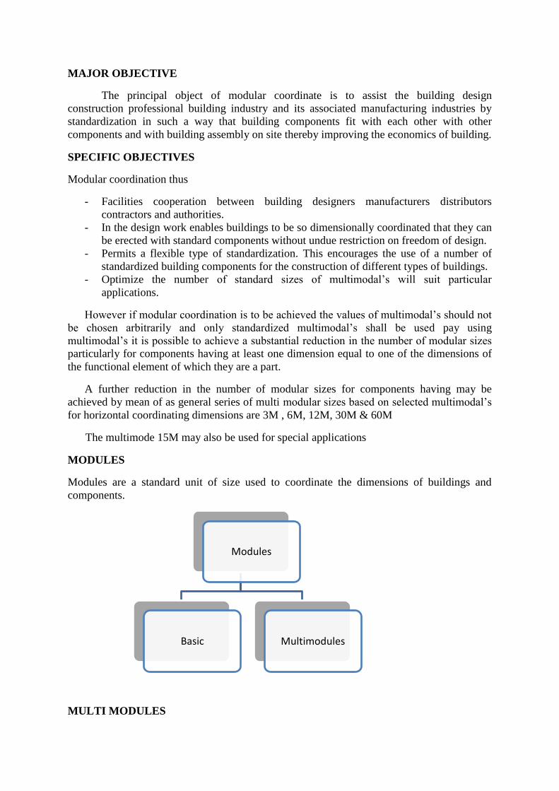
MODULES
Modules are a standard unit of size used to coordinate the dimensions of buildings and
components.
MULTI MODULES
Modules
Basic Multimodules

Multi modules are standardized selected whole multiples of the basic module different single
T beam has resulted the beam to fall 2 basement down. The beam just placed for connection.
BASIC MODULE
The fundamental module used in modular coordination the size of which is selected for
general application to buildings and components
MODULAR CO-ORDINATION DIMENSION:
1) The planning grid in both directions of the horizontal plan shall be:
a. 3m for residential and institutional buildings
b. For industrial buildings,
15M for spans up to 12m
30M for spans between 12m and 18m and
60M for spans over 18m
The centre lines of load bearing walls shall coincide with the grid lines.
2) Incase of external walls, the grid lines shall coincide with the centre line of the wall
50mm from the internal force.
3) The planning module in the vertical direction shall be 1M up to end including a height
of 2.8m, above the height of 2.8m it shall be 2M.
4) Preferred increments for sill heights, doors, windows etc. shall be 1M.
5) In case of internal columns, the grid lines coincide with the centre lines of columns. In
case of external columns and columns near the lift and stair wells the grid lines shall
coincide with centre lines of the column in the top most storey or a line in the column
50mm from the internal face of column in the top most storey.
Modular Grid
A rectangular coordinate reference system in which the distance between consecutive
lines is the basic module or a multi-module. This multi-module may differ for each of the two
dimensions of the grid.
Type of Modular Grid
There are different types of grid patterns which are used to locate the positions and
dimensions of building spaces components are
Elements in building design
Continuous grid
Superimposed grid
Displacement of grid (or) Tartan grids
Interrupted grids as neutral zones.
Continuous grid
Where all dimensions in either direction are based on one increment only.
Superimposed grids

When the modulur grid of 100 mm increment is superimposed on a multi-modular
grid.
Displacement of grid or tartan grids
Where there is a homogenous and repetitive relation between at least two basic increments.
Eg:- 1M +2M (or) 3/2 M + 3M
Interrupted grids (or) neutral zones
Where there are non modular interruptions of grids neutral zones are created to cope
with the economics of building design.
STANDARDIZATION
Standardization is to the creation and use of guidelines for the production of uniform
interchangeable components especially for use in mass production. It also refers to the
establishment and adoption of guidelines for conduct to global marketing the term is used in
describe the simplification of procurement & production to achieve economy
ADVANTAGES OF STANDARDIZATION
1) Easier in design as it eliminates unnecessary choices
2) Easier in manufacture as there are limited number of variants.
3) Makes repeated use of specialized equipments in erection and completion
4) Easier and quicker.
FACTORS INFLUENCING STANDARDIZATION:-
1) To select the most rational type of member for each element from the point of
production, assembly, serviceability and economy.
2) To limit the number of types of elements and to use them in large quantities.
3) To use the largest size of the extent possible, thus resulting in less number of joints.
4) To limit the size and number of prefabricate by the weight in overall dimension that
can be handled by the handling and erection equipment and by the limitation of
transportation.
5) To have all these prefabricates approximately of same weight very near to the lifting
capacity of the equipment.
SYSTEMS
The word system is referred to a particular method of construction of buildings by
using prefabricated components which are inter-related in functions and are produced to a set
of instructions with certain constraints. Several plans are possible using the same set of
components. The degree of flexibility varies from system to system.
CHARACTERISTICS OF A PREFABRICATION SYSTEM:-
The following characteristics among others are to be consideration devising a system.
1) Intensified usage of spaces.
2) Straight and simple walling scheme.
3) Limited sizes and number of components.
4) Limited opening in bearing walls.
5) Regulated locations of partitions.
6) Standardized service and stair units.
7) Limited sizes of doors and windows with regulated positions.
8) Structural clarity and efficiency.
9) Suitability for adoption in low rise and high rise blocks.
10) Ease of manufacturing, storing and transporting.
11) Speed and ease of erection.
12) Simple jointing system.
PREFABRICATED CONSTRUCTION SYSTEMS:-
The system of prefabricated construction depends on the extent of the use of prefabricated
components, their material, sizes and the technique adopted for their manufacture and use in
building. The various prefabrication systems are outlined below.
1) Small prefabrication
2) Medium prefabrication
3) Large prefabrication
4) Open prefabrication system
a. Partial prefabrication open system
b. Full prefabrication open system
5) Large panel prefabrication system
6) Wall system
a. Cross wall system
b. Longitudinal wall system
7) Floor system
8) Stair case system
9) Box type system
SMALL PREFABRICATION
The first 3 types are mainly classified according to their degree of precast elements
using in that construction. for eg:- brick is a small unit precasted and used in buildings. This
is called as small prefabrication. That the degree of precast element is very low.
MEDIUM PREFABRICATION
Suppose the roofing systems and horizontal member are provided with precast
elements. These constructions are known as medium prefabricated construction. Here the
degree of precast elements are moderate.
LARGE PREFABRICATION
In large prefabrication most of the members like wall panels, roofing/flooring
systems, beams and columns are prefabricated. Here degree of precast elements are high.
OFF-SITE (FACTORY) PREFABRICATION
One of the main factors which affect the factory prefabrication is transport. The width
of road walls mode of transport vehicles are the factors which factor the prefabrications
which is to be done on site or factory.
Suppose the factory situated at a long distance from the construction site and the vehicle have
to cross a congested traffic with heavy weighed elements the cost in-situ prefabrication is
preferred even though the same condition are the cast in site prefabrication is preferred only
when number of houses are more for small elements the conveyance is easier with normal

type of lorry and trailors. Therefore we can adopt factory (or) OFF site prefabrication for this
type of construction.
OPEN PREFABRICATION SYSTEM:-
This system is based on the use of the basic structural elements to form whole or part of
a building. The standard prefabricated concrete components which can be used are,
1) Reinforced concrete channel units
2) Hollow core slabs
3) Hollow blocks and battens
4) Precast plank and battens
5) Precast joists and tiles
6) Cellular concrete slabs
7) Prestressed / reinforced concrete slabs
8) Reinforced / prestressed concrete slabs
9) Reinforced / prestressed concrete columns
10 Precast lintels and sunshades
11 Reinforced concrete waffle slabs / shells
12 Room size reinforced / prestressed concrete panels
13 Reinforced / prestressed concrete walling elements
14 Reinforced / prestressed concrete trusses
The elements may be cost at the site or off the site.
Foundation for the columns could be of prefabricated type of the conventional cast in
situ type depending upon the soil conditions and loads. The columns may have hinged or
fixed base connections depending upon the type of components used and the method of
design adopted.
There are two categories of open prefabricated systems depending on the extent of
prefabrication used in the construction as given below.
1) Partial prefabrication open system
2) Full prefabrication open system
PARTIAL PREFABRICATION OPEN SYSTEM:
The system basically emphasizes the use of precast roofing and flooring components
and other minor elements like lintels, sunshades, kitchen sills in conventional building
construction. The structural system could be in the form of insitu frame work or load bearing
walls.
FULL PREFABRICATION OPEN SYSTEM:
In this system, almost all the structural components are prefabricated. The filler walls
may be of bricks or of any other local materials.
LARGE PANEL PREFABRICATION SYSTEM:

This is based on the use of large prefabricated components. The components used are
precast concrete large panels for walls, floor roofs, balconies, stair cases etc. The casting of
the components could be at the site or off the site.
Depending upon the context of prefabrication, this system can also lend itself to
partial prefabrication system and full prefabrication system.
WALL SYSTEM:
Structural scheme with precast large panel walls can be classified as
1) Cross wall system
2) Longitudinal wall system
CROSS WALL SYSTEM:
In this system the cross walls are load bearing walls. The facade walls are non-load
bearing. This system is suitable for high rise buildings.
LONGITUDINAL WALL SYSTEM:
In this system, cross walls are non-bearing, longitudinal walls are load bearing. This
system is suitable for low rise buildings.
A combination of the above systems with all load bearing walls can also be adopted.

Precast concrete walls could be
1) Homogeneous walls
2) Non-homogeneous walls
Homogeneous walls:
The walls could be solid or ribbed.
Non-homogeneous walls:
Based on the structural functions of the walls, the walls could be classified as
a. Load bearing walls
b. Non-load bearing walls
c. Shear walls
Based on their locations and functional requirements the walls are further classified as
(i) External walls which can be load or non-load bearing depending upon the
layout. They are usually non-homogeneous walls of sandwiched type to impart
better thermal comforts.
(ii) Internal walls which provide resistance against vertical loads, horizontal loads,
fire etc. and are normally homogeneous.
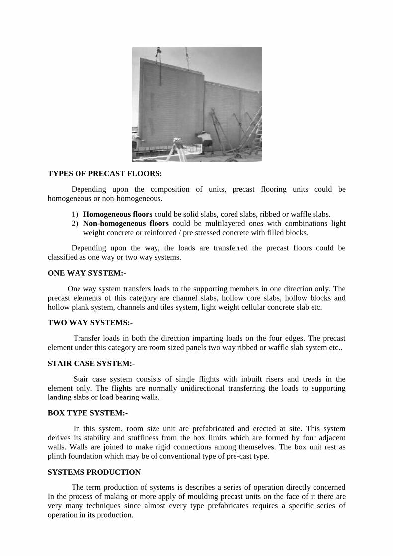
TYPES OF PRECAST FLOORS:
Depending upon the composition of units, precast flooring units could be
homogeneous or non-homogeneous.
1) Homogeneous floors could be solid slabs, cored slabs, ribbed or waffle slabs.
2) Non-homogeneous floors could be multilayered ones with combinations light
weight concrete or reinforced / pre stressed concrete with filled blocks.
Depending upon the way, the loads are transferred the precast floors could be
classified as one way or two way systems.
ONE WAY SYSTEM:-
One way system transfers loads to the supporting members in one direction only. The
precast elements of this category are channel slabs, hollow core slabs, hollow blocks and
hollow plank system, channels and tiles system, light weight cellular concrete slab etc.
TWO WAY SYSTEMS:-
Transfer loads in both the direction imparting loads on the four edges. The precast
element under this category are room sized panels two way ribbed or waffle slab system etc..
STAIR CASE SYSTEM:-
Stair case system consists of single flights with inbuilt risers and treads in the
element only. The flights are normally unidirectional transferring the loads to supporting
landing slabs or load bearing walls.
BOX TYPE SYSTEM:-
In this system, room size unit are prefabricated and erected at site. This system
derives its stability and stuffiness from the box limits which are formed by four adjacent
walls. Walls are joined to make rigid connections among themselves. The box unit rest as
plinth foundation which may be of conventional type of pre-cast type.
SYSTEMS PRODUCTION
The term production of systems is describes a series of operation directly concerned
In the process of making or more apply of moulding precast units on the face of it there are
very many techniques since almost every type prefabricates requires a specific series of
operation in its production.
These techniques however may be grouped into three basic method of production. These are
1. The stand system
2. The conveyor belt or production line system
3. The aggregate system
Stand system
In the stand system the prefabricates mature at the point where they were moulded
While the production team moves to successive stands the bed on which prefabricates.
Conveyor belt
The conveyor belt system of production splits the whole production process in to a
series of operation carried out at a separate successive and permanent point to the heat may
be by means of conveyor belt trolleys & crane etc.
Aggregate system
The word aggregates describes a large, complex permanently installed set of machines
and mechanical application which can carry out most of the separate operation involved in
casting concrete components.
PRODUCTION
The location of precasting yards consist of storage facilities suitable for transporting
and erection equipments and availability of raw materials are the critical factors which should
be carefully planned and provided for effective and economic use of pre-cast concrete
components in construction.
The manufacture of the components can be done in a centrally located factor of in a site
where precasting yards set-up at or near the site of work.
FACTORY PREFABRICATION;
Factory prefabrication is restored in a centrally located plant for manufacture of
standardized components on a long form basis.
It is a capital intensive production where work is done throughout the year preferably under a
covered shed to avoid the effects of seasonal variations high level of mechanization can
always be introduced in this system where the work can be organized in a factory like manner
with the help of constant team of workmen.
The basic disadvantage in factory prefabricated, is the extra cost in occurred in transportation
of elements from plant to site of work sometimes the shape and size of prefabricable are to
be limited due to lack of suitable transportation equipment roads controls etc.
SITE PREFABRICATION:
In this scheme, the components are manufactured at site near the site of work as
possible. This system is normally adopted for a specific job order for a short period. The

work is normally carried out in open space with locally a valuable labour force. The
equipment machinery and moulds are of mobile nature.
Therefore there is a definite economy with respect to cost of transportation. This
system suffers from basic drawback of its non-suitability to any high degree of
mechanization. It has no elaborate arrangements for quality control.
PROCESS OF MANUFACTURE:
The various processes involved in the manufacture of precast elements are
classified as follows:
1) Main process
2) Secondary (auxiliary) process
3) Subsidiary process
MAIN PROCESS:
It involves the following steps.
1) Providing and assembling the moulds, placing reinforcement cage in position for
reinforced concrete work, and
2) Fixing of inserts and tubes where necessary.
3) Depositing the concrete in to the moulds.
4) Vibrating the deposited concrete into the moulds.
5) Demoulding the forms.
6) Curing (steam curing if necessary)
7) Stacking the precast products.
SECONDARY (AUXILLARY) PROCESS:
This process is necessary for the successful completion of the process covered by the
main process.
1) Mixing or manufacture of fresh concrete (done in a mixing station or by a matching
plant).
2) Prefabrication of reinforcement cage (done in a steel yard of workshop)
3) Manufacture of inserts and other finishing items to be incorporated in the main
precast products.
4) Finishing the precast products.
5) Testing the precast products.
STAGES OF PREFABRICATED CONCRETE PRODUCT:
FLOW DIAGRAM OF STAGES OF PROCESSING
CONCRETE---------MOULD-----------------STEEL
MIXING--------------PREPARATION--------CUTTING
FILLING----------------------------------------REINFORCING
COMPONENT
COMPACTION

CURING
DEMOULDING
STORAGE
PRODUCTION TOLERANCE (T)
The limits of deviation in the dimensions (Δs) T/2 the shape of the prefabricates. This
depends very much on the type of moulds, wooden, steel, concrete or plastic the tolerance
also depends on the nominal dimension, nature of prefabricate and its position during casting.
Degree of
accuracy
≤10 cm › 10 cm
≤ 30 cm
730 cm
≤ 3 m
3 m
≤ 9 m
› 9 m
4
5
6
7
8
1 mm
2 mm
3 mm
4 mm
6mm
2 mm
3
4
6
10
3 mm
4
6
10
15
4 mm
6
10
15
25
6 mm
10
15
25
30
TRANSPORT
Transport of prefabrication elements must be carried out and with extreme care to
avoid any flock and distress in elements and handled as far as possible to be placed in final
portion
Transport of prefab elements inside the factory depends on the method of production
selected for the manufacture.
Transport of prefab elements from the factory to the site of action should be planned
in conformity with the trafficable rules and regulations as stipulated by the authouritic the
size of the elements is often restricted by the availability of suitable transport equipment,
such as tractor-am-tailor, to suits the load and dimension of the member in addition to the
load carrying capacity of the bridges on the way.
While transporting the prefab elements in various systems, such as wages, trucks,
bullock cards etc. care should be taken to avoid excessive cantilever actions and desired
supports are maintained. Special care should be taken in negotiating sharp beds uneven of
slushy roads to avoid undesirable stresses in elements and in transport vehicles.
Before loading the elements in the transporting media, care should be taken to ensure
the base packing for supporting the elements are located at specified portion only.
ERECTION
It is the process of assembling the Prefabrication element in the find portion as per the
drawing. In the erection of prefab elements the following items of work are to be carried out.
1).Slinging of the prefab elements.
2).Tying up of erection slopes connecting to the erection hooks.
3).Cleaning the elements and the site of erection.
4).Cleaning the steel inserts before incorporation in the joints lifting and setting the elements
to correct position.
5).Adjustments to get the stipulated level line and plumb.
6).Welding of cleats.
7).Changing of the erection tackles.
8).Putting up and removing the necessary scaffolding or supports.
9).Welding the insorts laying the reinforced in joints.
The erection work in various construction jobs by using prefab elements differs with
risk condition, hence skilled foremen, and workers to be employed on the job.
Equipments required for erection
Equipments required for the prefab elements in industry can be classified as.
1) Machinery required for quarrying of course and fine aggregates
2) Conveying equipment, such as but conveyor, chain conveyors etc.
3) Concrete mixers
4) Vibrators
5) Erection equipment such as cranes, derricks, chain pulley etc.
6) Transport machines
7) Work shop machinery for fabricating and repairing steel.
8) Bar straitening, bending and welding machines
9) Minor tools and takes, such as wheel barreriour, concrete buckets etc…
10) Steam generation a plant for accelerated curing
Planning co-ordination
It is important to have the precaster erector/installer and builder working together to
achieve best performance.
Site Access and storage
Check for site accessibility and precast panels delivery to site especially low
bed trailers
Check whether adequate space for temporary storage before installation and
ground conditions. (firm ground & levelled)
Uneven ground will cause overstress & crack panels.
Planning crane Arrangement
Plan the crane capacity and lifting gears based on
Heaviest weight of precast panels
Lifting heights.
Working radius
Position of crane in relation to final panel location
Plan other equipments
Boom lift and scissor lift for unhooking installed panels.
Lifting gears
Skilled personnel’s
Competent crane operators
Rigger
Signalled etc
General considerations for crane selection

Total lifting weight
Crane model
Crane safe working load (SWL)
(i.e) Based on 15% capacity build in F.O.S. 1.33
o Lifting capacity must be 1.5 times the total weight i.e) F.O.S 1.5
Lifting and swing radius
Crane counter weight
Crane boom length is relation to the vertical and horizontal clearance from the
building.
Installation Process
Installation of vertical components
Verification of Delivered Panels
Check the panels delivered for correct marking lifting hook and position etc.
Surface finishing condition
Pc Dimension compliance
Reinforcement Provision/position
Architectural Detail compliance
1. Setting out
Check the panels delivered for marking, lifting hook and condition.
Set the reference lines & grids
Check starter bars for vertical components before hoisting for installation
2. Setting out Quality control point
Ensure correct offset line
Check shim pedal/plate level and firm
Rubber gasket property secured
For external wall/column place backer rod.
3. Hoisting, Rigging and Installation
While tilting provide rubber pad to avoid chip off.
Lift and rig the panel to designated location
Adjust the panel in position and secure
Lifting of space adding items with balanced centre of gravity.
Ensure horizontal alignment correct
Ensure panel vertically to correct plumb
Check panel to panel gap consistency
Check stability of prop before releasing hoisting cable.
4. Grouting works
Prepare and apply non shrink mortars to seal
For corrugated pipe sleeve on splive sleeve pour NSGT or proprietary grouts
into pipe slab.
Keep installed panels undisturbed for 24 hrs.
Check joint widths are consistent before grouting
Grout used should be same grade of components and self compacting to
prevent cracking.
Collect test cube sample for testing for critical element or load bearing
elements

5. Connecting joints
Cast in situ joints install rebars as required
Set up forms for casting joints
Do Concreting
Remove forms after sufficient strength
For external connections sealant shall be used
Panel with welded connections welding as required
Installation of Horizontal Elements
1. Setting out
Set reference line/offset line to required alignment and level of slab/beam
during installation
Put temporary prop to support the precast slab/beam elements
Before Hoisting chem. Dimensions
Check level and stability of shim
Check protruding/ starter bars are within the Specified tolerance to prevent
any observation during the erection process
2. Hoisting & Installation
Put temporary props to support slab/beam
Lift and rig the elements in designated location
Align and check the level before placement
The beams shall prop atleast 2 location
Balcony planter box and shall be supported more than 2 location based on
design considerations
Check level of precast elements
3. Connections/Jointing
Precast with cast-in-situ joints place the lap rebars as required
Set formwork for casting joints
Remove formwork after concrete strength is achieved
Supporting beams shall be designed to form part of formwork joints
The connecting/lapping rebars tied & secured
Same grade of concrete 10 to be used that of panel.
4. Installation using Big canopy
Big canopy high rise precast concrete construction system
This is used for faster and efficient
5. Erection Purpose
In Japan
o Used to construct the 26 storey pre-cast concrete 30,763m2
o The system realized 60% reduction in labor requirement for the
frame erection.
In Singapore o DBS China square used the system to erect is efficient and
faster
6. Installation constraints Management Example
The project requires precast panel to install 2 basements down.
Constraint
Temporary Decking for various for various works.
Cross bracing with king posts

No direct access for panels
7. Management
Roller frame and plat form was laid.
The panels lowered in roller platform
Push to underneath deck where panel is required
Remove of one deck panel to lift and install panel in correct position.
8. Mishandling of precast panels
Case Study
The hollow core slab was in the process of installation it was placed on the
beam corbel
For making adjustment in position the panel was lifted.
During lifting the panel was broken
Case of Failure
The panel was designed for simply supported condition
The lifting position with over 3 m cantilevered edge that has resulted panel
damage.
Remediation
Use appropriate lifting position
Seek advice from precaster
9. Common Defects in precast panels The common defects to hole in precast panels before installation panel before
installation.
Panel not property touch up.
Damage due to insufficient protection during delivery
Panel dimension deviation
Panel twisted no rectangular
Wrong rib and architectural detail
Missing starter bar or as wrong position
Corrugated pipe duck choked
10. Precast failures
Bridge Deck collapse
Causes reported as inadequate lap length of rebar at cantilevered deck and pier
rebar.
Single T beam collapse
Cause reported as impact lend on the rebar.
TOLERANCE:
It is the sum of acceptable positive and negative discrepancies of actual dimensions
from the theoretical one. The limits of tolerance are based on the manufacture and erection
requirements.
ERECTION TOLERANCE:

These are the limits of deviation of the positioning in the assembly of the
prefabricates. The position tolerance are normally defined by five components namely,
deviation in positioning of the prefabricates in x,y,z, directions (Δx,Δ y,Δ z)and deviation in
positioning with respet to another prefabricate. (Δp) and the deviation in the verticality of the
prefabricate(Δp).
Degree of
Accuracy
Δx,Δ y Δ z Δp Δp
5
6
7
8
6 mm
10
15
25
4 mm
6
10
15
3 mm
4
6
10
4 mm
6
8
12
UNIT II
PREFABRICATED COMPONENTS
Behaviour of structural components large panel construction of roof & floor slabs
walls panels columns shear wall.
Structural Behaviour of Precast structures
a) The design load carrying structures advantages from the viewpoint of prefabrication.
b) Principle of structural analysis
c) Various specifications
d) Dimensioning of joints
e) Elimination of handling stresses
f) Redistribution of stresses in jointed structures due to creep & shrinkage.
g) Calculation of reinforced concrete structures co-operating with strengthening concrete
layer cast in situ.

h) Influence of the sequence and of the method of placing on the stress state of the
structure
i) Stability of precast structural members
j) Quantity of materials used for precast reinforced concrete structures.
STRUCTURAL COMPONENTS
The following are the main components which are frequently used in building are
Slab
Joist
Beams (main secondary)
Wall panels
Columns
The roofing/flooring system consists of R.C planks and joists. The planks are casted to a
standard size and they are connected with R.C.C joist which are provided at a regular
interval. The loads from planks are transmitted to R.C joist and then to main beams.
The main beams are provided with channel sections 10 cm projections on the necessary sides
with the spacing of joist. The joists are seated in the channels and bolted together.
The loads from slab to the main beam will loadings are analysed. The foundation unit is the
only unit which is going to cast in site.
Slab
The roofing slab/flooring slab system consists of planks, which is supported over
R.C.C Joist. The planks can be made in any one of the following form with or without
prestressing. According to the span & loads.
1. Hollow core sections
2. Double tee section\Channel sections
3. Light weight concrete roofing slab
4. Solid rectangular planks
The usual widths of these types of slabs are 0.5 m & spanning to the requirement upto a
maximum limit of 5 m without prestressing. The thicknesses of planks are casted in two steps
with different mould in access invisible action with adjacent slab by putting necessary
reinforcement & concreting site.
Joist
The joists are designed as a small beams loaded from planks. These joists transmit the
loads to the main beams through the channels provided in the main beams in this joist,
triangular shaped stirrups are provided to get the proper bonding or connection with the
planks. The joists are casted partially in the factory the apex portion of the triangular stirrup
will be projecting from the casted top surface. In this projecting a connecting rod will be
inserted and additional base from planks also inserted. This will give monolithic action as
well as the plank will act as a continuous slab over the joists.
Beams (Main & Secondary)
All the main and secondary beams are the same size of 300 x 300 mm varies
reinforcements are provided at varies conditions according to the moments. The beams are
casted for the clear distance between the columns. A square of 10 cm x 10 cm hole or a depth
of 10 cm are provided on either side to achieve the connection with other beam reinforcement
or column reinforcements by proper welding. After welding the concrete has to be done at the
junction with proper care. At the junction of columns and beams it is necessary or part site
controlling for this purpose the top ends of the beams are trap pored properly. So that it with
give access to site concrete and for needle vibrators to get proper compaction.
Wall Panels
The wall panels are casted with all fixing like door, ventilation, window frames.
These wall panels are non load bearing wall. Therefore neglect solid rectangular cross section
wall panel with R.C.C. from the view of thermal effects and safety the minimum of 150 mm
is provided as wall thickness. This wall is a sandwich type. That is cellular concrete blocks of
75 mm thick is sandwiched by R.C.C. M25 grade concrete to a thickness of 37,5 mm on either
face with minimum reinforcement since, the walls are in steel moulds there will be no used to
plastering on either face of wall.
This is one of advantage of precast wall panels. The main design factor is the handling
stresses in wall panels.
The infillings may be any light weight, low cost material like brick bats, bricks light weight
concrete acquainted concrete etc. Since the preparation and availability of raw materials are
easy in the case of cellular concrete we are adopting cellular concrete as infill’s in walls.
Columns
Many type of columns available in prefabricated system. Grooves are provided on the
required faces to keep the walls in position. These grooves will act as a part of columns and
since the area of column has been increased due to tibs will give addition moment carrying as
well as load carrying capacity of columns. At the same time this grooves give a mild
ornamental look to our building.
Construction of roof & floor slabs wall panels
Description
Precast components are 85% recyclable, levels of carbon dioxide generation is low
energy efficient reduces waste during operations reduce construction cost eco friendly. Easy
to install reduces construction time stronger than cost in situ structures can be pre-stressed or
post stressed is increase its performance longer life of structure, saves reinforcement and a in-
line manufacturing process reduces the amount of waste generated casting.
It can be manufactured in mechanized centralized production centres in a variety of shapes
and sizes. Its properties can be altered by altering the constituent raw materials like using
cellular/aerated concrete or light weight aggregates etc, they may also be produced to have
higher thermal insulating values by manufacturing sandwich panels with the integration of
insulating material like polyurethane etc giving this product/technology a great advantage.
Performance of the Components
1. Appearance
In prefabricated construction, there is better quality control shape and size of precast
element. The concrete panels with have a light gray concrete colour and have a smooth even

finish due to high quality mechanized centralized mass production units. Reduction in the
number of joints gives a neat clean image.
2. Structural Capability
Strict quality control system can be put into place to ensure high performance in structural
design full advantage of properties of cement and steel can be exploited. A regular RCC slab
of 125 mm thickness could actually be only 65mm thick to cater to the load above since on
site formwork limitations do not permit such thin sections one has to cast a minimum 125mm
thick slab. A 50% reduction in the cross section area means a similar reduction in the material
consumption and dead load on the structural system pre-cast element can be used efficiently
for most of the building components.
Pre-cast slabs and beams can be designed to carry live/dead loads as per requirements
with safety factors incorporated. Additional reinforcement could be placed while filling up
joints. In slabs provided with interlocking system to avoid independent displacement of slabs
must be manufactured with M40 grade concrete in give durable and stronger slab than cast in
situ slabs.
Pre-cast waffle units provide speedy construction with overall saving up to 10% or more,
besides avoiding shuttering work. The shape is like an inverted through with square or
rectangular in plan having lateral dimension up to 1.2 m suitable for large spans beyond 6m
in either direction on laying in grid pattern with reinforcement and cast-in-situ concrete joints
between them.
3. Thermal Properties
As the pre-cast units have thinner cross sections, components used in roofs or walls
should be provided with adequate thermally insulating coverings for better thermal
performance. This thermal insulation can come as a integral part of the unit during the
manufacture of the pre-cast units as a sandwich, insuring good thermal properties and ease of
use or could be added on as a independent insulation layer of required value like in dry
normal construction practice.
4. Sound Insulation
Pre cast concrete units provide an acceptable degree of sound insulation. Their
performance can be improved by the addition of sound insulating material as in sandwich
during the manufacturing process.
5. Fire and Vermin resistance
Pre cast concrete panels will not burn. They are readily incorporated into fire resistant
rated construction with fire rating achievable up to 4 hrs. It has no problems of Vermin
attacks or infestation and is also resistance to mold formation.
6. Durability & moisture resistance
Due to strict quality control measures safe structural design with adequate
reinforcements precast panels are highly durable and low on maintenance. They perform
well even under high humidity conditions or constant wetting. Water absorption is low
and most cases do not need a water proofing coat even in external applications.
7. Toxicity and breath ability
Pre cast panels are inert non-toxic and not prone to off gassing of volatile materials.
As the production of these units lakes place in a controlled environment pollution of air,
water and site can be reduced and controlled.
8. Sustainability (Environmental impacts)
There is disciplined use of scarce material like cement steel and timber during the
production and use installation of these pre-cast panels. Although there would be a
component of transportation involved from the production centers to the site, it helps in
the management of raw materials in an efficient way away from the site reducing the
work at the site decreasing on site pollution and keeping the work qualitatively better and
reliable. In pre-cast construction similar types of components are produced repeatedly
resulting in increased productivity and economy in cost too.
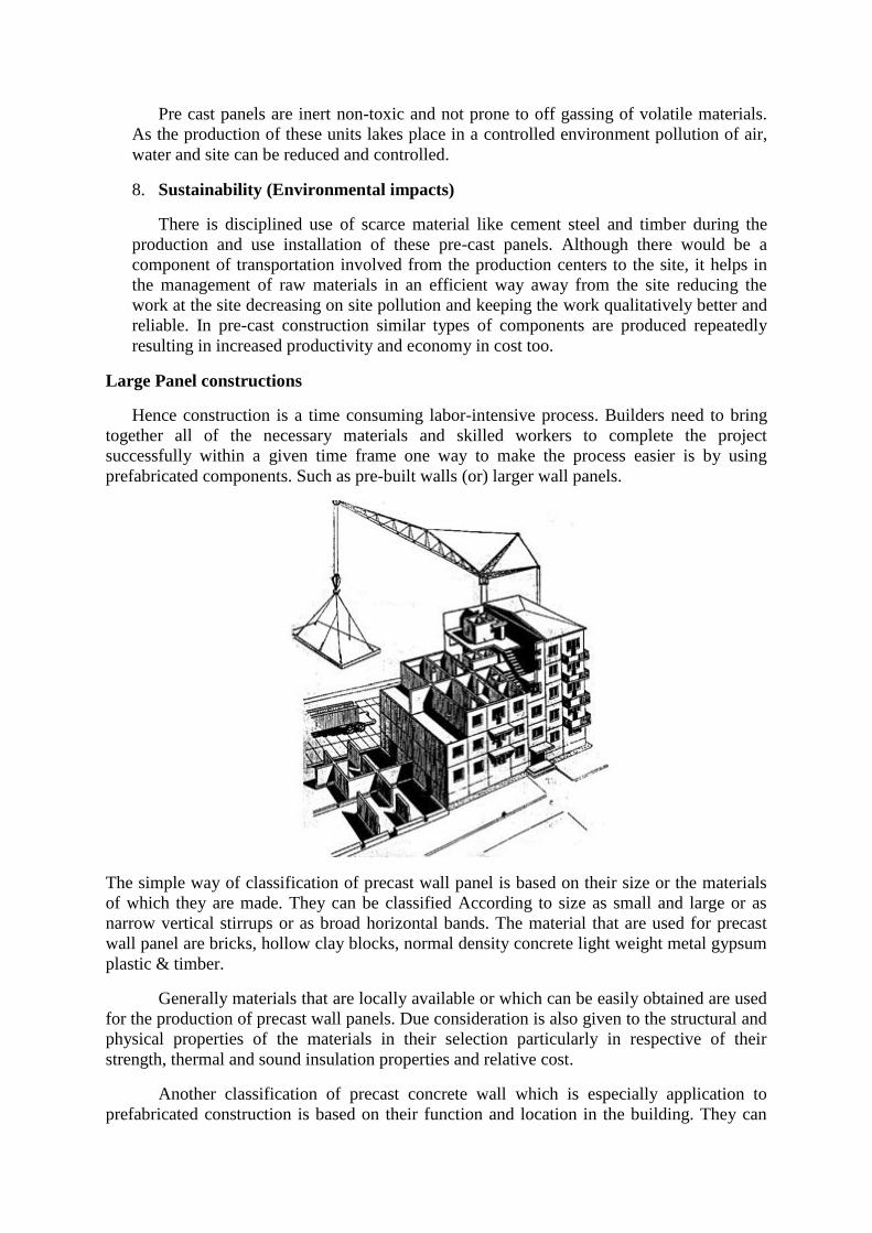
Large Panel constructions
Hence construction is a time consuming labor-intensive process. Builders need to bring
together all of the necessary materials and skilled workers to complete the project
successfully within a given time frame one way to make the process easier is by using
prefabricated components. Such as pre-built walls (or) larger wall panels.
The simple way of classification of precast wall panel is based on their size or the materials
of which they are made. They can be classified According to size as small and large or as
narrow vertical stirrups or as broad horizontal bands. The material that are used for precast
wall panel are bricks, hollow clay blocks, normal density concrete light weight metal gypsum
plastic & timber.
Generally materials that are locally available or which can be easily obtained are used
for the production of precast wall panels. Due consideration is also given to the structural and
physical properties of the materials in their selection particularly in respective of their
strength, thermal and sound insulation properties and relative cost.
Another classification of precast concrete wall which is especially application to
prefabricated construction is based on their function and location in the building. They can
also be distinguished for their cross sectional characteristics. As regards their location the
wall panels may be classified as exterior or interior location walls.
Depended on their function they may be either structural (load bearing) or non-
structural (non-load bearing) elements. They may be of solid ripped sandwich hollow core, or
composite construction they can be either prestressed or conventionally reinforce.
In large panel construction the load bearing wall may be laid out either perpendicular
to the longitudinal axis of the building (cross wall system) or parallel to it ( spine wall
system). A mixed system consists of cross wall and spine wall system. In most Vertical load
carrying elements transfer their loads directly to the foundation without an intermediate frame
Classification of precast large panel
Structural scheme with precast large panel wall can be classified as
1. Cross wall system
2. Longitudinal wall system
Cross wall system
In this scheme the cross wall are load bearing walls where as the façade wall are non-
loading bearing this system is suitable for high rise building.
Longitudinal wall system
In this case cross walls are non-load bearing whereas longitudinal walls are load bearing
walls. This system is suitable for low rise buildings. A combination of the above systems
with all loads bearing wall can also be adopted.
a) Homogeneous wall
The homogeneous wall should be solid hollow or ribbed.
b) Non-homogeneous wall
These could be composite or sandwich panal based on the structural fuctions of the walls,
the wall could be classified as
i. Load bearing walls
ii. Non load bearing walls
iii. Shear walls
Based on their locations and functional requirements the walls are also classified as
1. External walls
2. Internal walls
1. External Walls which can be load bearing depending up to the layout and are usually
non homogeneous walls of sandwiched typed to impart better thermal comforts.
2. Internal walls providing resistance against vertical loads horizontal loads, fire etc. and
are normally homogeneous walls.
CONSTRUCTION OF ROOF AND FLOOR SLABS
Roofing members:-
Roofing members can be divided in to two groups’ short span and long span roofing
members. The short span members rest on purlins. While long span ones are directly
supported by the main girders.
The short span roofing members the reinforced plan mode of porous hollow tiles, light weight
concrete, roofing material and small reinforced concrete roofing members will be dealt with
here.
Among the long span roofing members the reinforced concrete members are discussed.
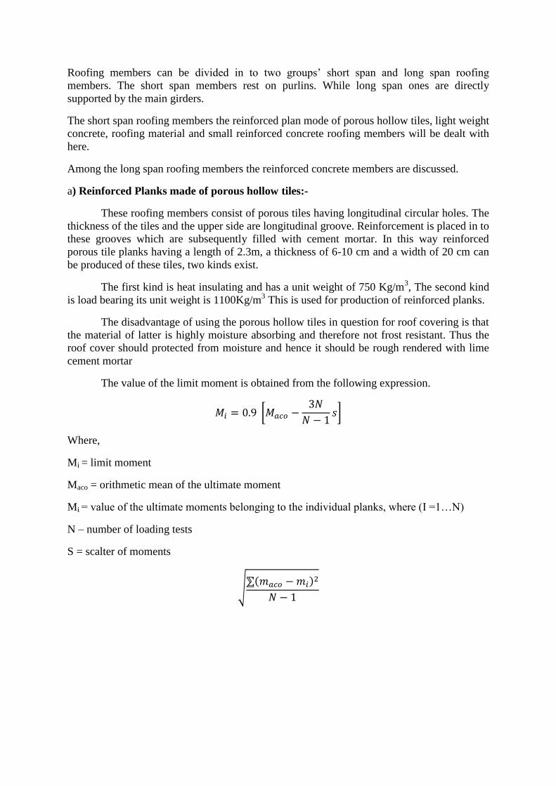
a) Reinforced Planks made of porous hollow tiles:-
These roofing members consist of porous tiles having longitudinal circular holes. The
thickness of the tiles and the upper side are longitudinal groove. Reinforcement is placed in to
these grooves which are subsequently filled with cement mortar. In this way reinforced
porous tile planks having a length of 2.3m, a thickness of 6-10 cm and a width of 20 cm can
be produced of these tiles, two kinds exist.
The first kind is heat insulating and has a unit weight of 750 Kg/m3, The second kind
is load bearing its unit weight is 1100Kg/m3 This is used for production of reinforced planks.
The disadvantage of using the porous hollow tiles in question for roof covering is that
the material of latter is highly moisture absorbing and therefore not frost resistant. Thus the
roof cover should protected from moisture and hence it should be rough rendered with lime
cement mortar
The value of the limit moment is obtained from the following expression.
[
]
Where,
Mi = limit moment
Maco = orithmetic mean of the ultimate moment
Mi = value of the ultimate moments belonging to the individual planks, where (I =1…N)
N – number of loading tests
S = scalter of moments
√ ( )
An 8cm thik plank of porous hollow tiles and its reinforcement.
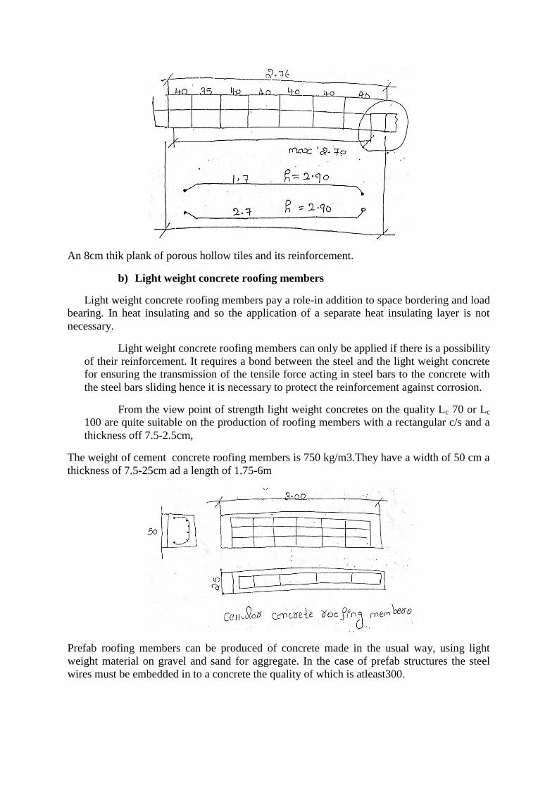
b) Light weight concrete roofing members
Light weight concrete roofing members pay a role-in addition to space bordering and load
bearing. In heat insulating and so the application of a separate heat insulating layer is not
necessary.
Light weight concrete roofing members can only be applied if there is a possibility
of their reinforcement. It requires a bond between the steel and the light weight concrete
for ensuring the transmission of the tensile force acting in steel bars to the concrete with
the steel bars sliding hence it is necessary to protect the reinforcement against corrosion.
From the view point of strength light weight concretes on the quality Lc 70 or Lc
100 are quite suitable on the production of roofing members with a rectangular c/s and a
thickness off 7.5-2.5cm,
The weight of cement concrete roofing members is 750 kg/m3.They have a width of 50 cm a
thickness of 7.5-25cm ad a length of 1.75-6m
Prefab roofing members can be produced of concrete made in the usual way, using light
weight material on gravel and sand for aggregate. In the case of prefab structures the steel
wires must be embedded in to a concrete the quality of which is atleast300.

Roofing
B) Small reinforced – Concrete roofing members;
The small reinforced – concrete roofing member is essentially a precast simply
supported, ribbed reinforced – concrete slab .The width of the member is 50 – 120 cm.
C) Large reinforced concrete roofing members:
The large reinforced – concrete roofing members resting directly on the main girders
of structures represents a more advanced kind of precast roofing structure .These members
are manufactured in a length corresponding to the spacing of the frames ( 6 – 10 m ),their
width is 1.30 – 1.80 m. They are directly supported by the main girders so that purlins are not
required.
A large roofing member consists of two longitudinal edge ribs, cross ribs and a slab
having a thickness of 2.5 – 3 m and the two way reinforcement. The members connected to
each other and to the frame girders form a unified continuous roofing structure.
FLOORING MEMBERS
In industrial buildings the use of prefab members, for floor consist of precast joints
and flooring members.
The flooring member is designed for a span of 9m and for the bearing of a live load of 1000
kg/m2. After the members are placed in final positions a longitudinal load bearing
reinforcement and stirrups are placed in the trough formed between the longitudinal ribs of
the adjacent members. A continuous reinforcement is placed on the top of these members,
there after a 5 cm thick insitu concrete layer is cast on the top of the members and the troughs
between the longitudinal ribs are also filled up with concrete. In this way the slab is
transformed into a continuous.
A prestressed flooring member for a span of 6m and live load of 500 kg/m2 and a wt of 1450
kg are widely used.
Flooring members to be used for smaller loads similarly to roofing members can also be
made of lightweight concrete. These members are used cheaply in house and public building.
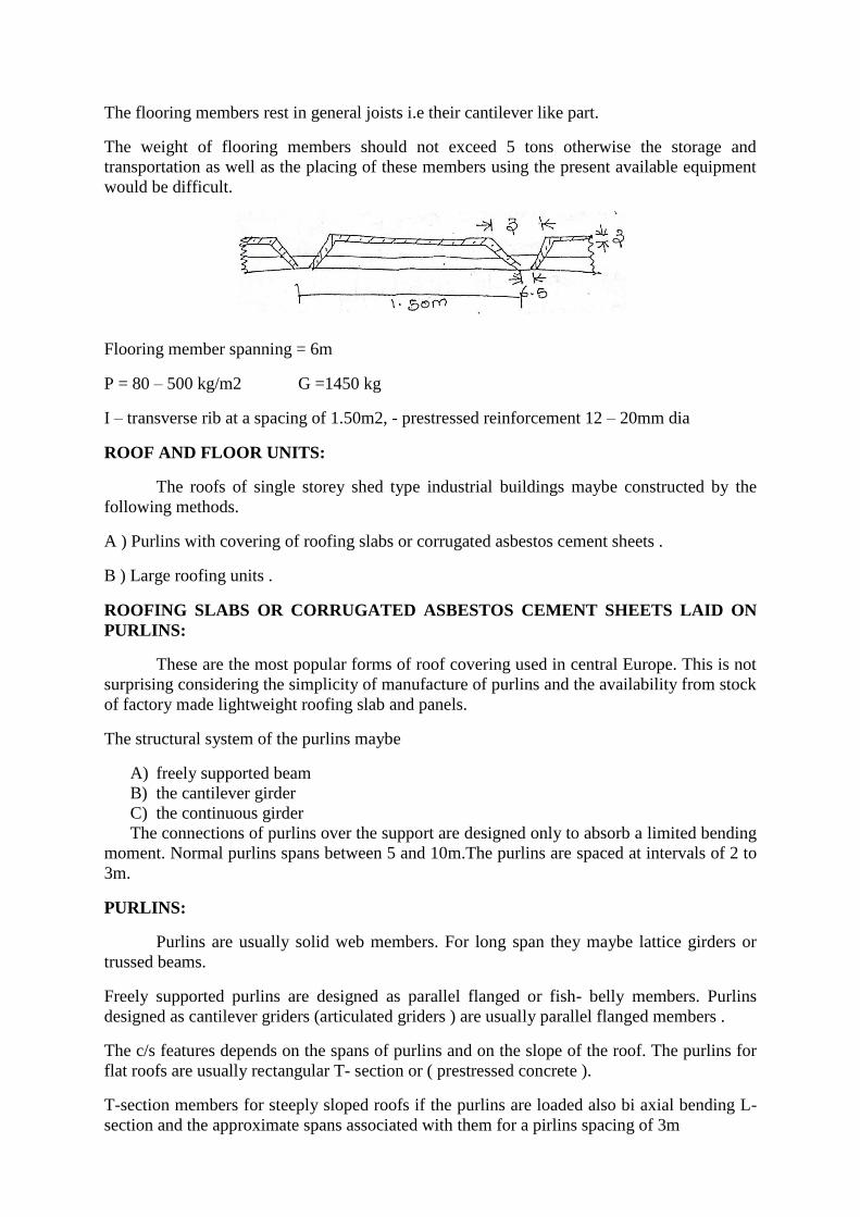
The flooring members rest in general joists i.e their cantilever like part.
The weight of flooring members should not exceed 5 tons otherwise the storage and
transportation as well as the placing of these members using the present available equipment
would be difficult.
Flooring member spanning = 6m
P = 80 – 500 kg/m2 G =1450 kg
I – transverse rib at a spacing of 1.50m2, - prestressed reinforcement 12 – 20mm dia
ROOF AND FLOOR UNITS:
The roofs of single storey shed type industrial buildings maybe constructed by the
following methods.
A ) Purlins with covering of roofing slabs or corrugated asbestos cement sheets .
B ) Large roofing units .
ROOFING SLABS OR CORRUGATED ASBESTOS CEMENT SHEETS LAID ON
PURLINS:
These are the most popular forms of roof covering used in central Europe. This is not
surprising considering the simplicity of manufacture of purlins and the availability from stock
of factory made lightweight roofing slab and panels.
The structural system of the purlins maybe
A) freely supported beam
B) the cantilever girder
C) the continuous girder
The connections of purlins over the support are designed only to absorb a limited bending
moment. Normal purlins spans between 5 and 10m.The purlins are spaced at intervals of 2 to
3m.
PURLINS:
Purlins are usually solid web members. For long span they maybe lattice girders or
trussed beams.
Freely supported purlins are designed as parallel flanged or fish- belly members. Purlins
designed as cantilever griders (articulated griders ) are usually parallel flanged members .
The c/s features depends on the spans of purlins and on the slope of the roof. The purlins for
flat roofs are usually rectangular T- section or ( prestressed concrete ).
T-section members for steeply sloped roofs if the purlins are loaded also bi axial bending L-
section and the approximate spans associated with them for a pirlins spacing of 3m
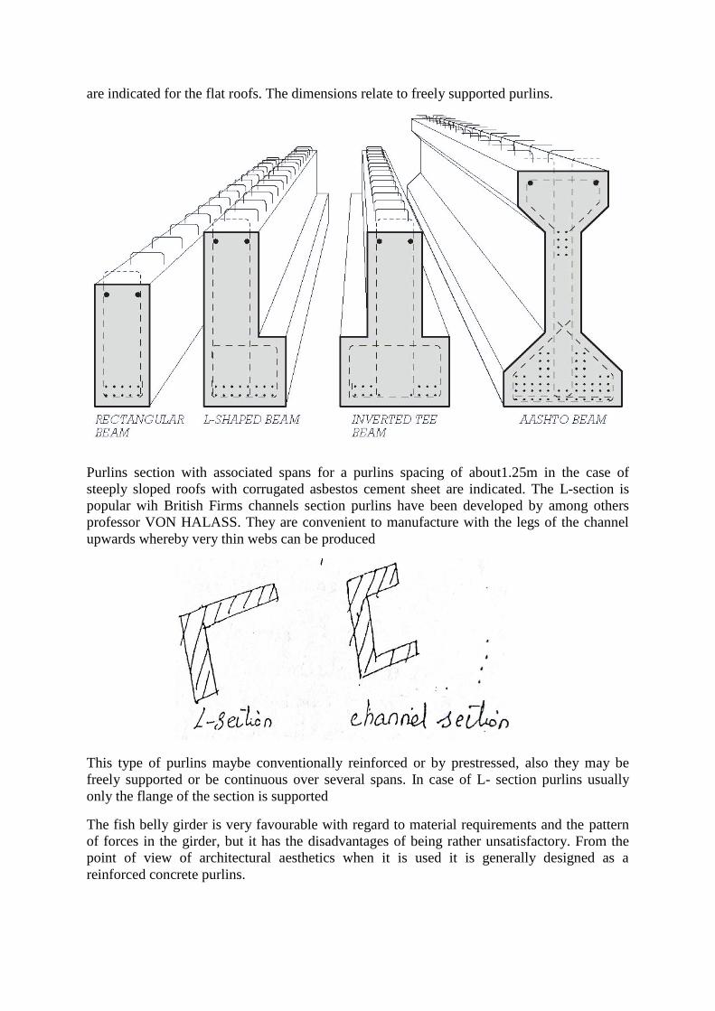
are indicated for the flat roofs. The dimensions relate to freely supported purlins.
Purlins section with associated spans for a purlins spacing of about1.25m in the case of
steeply sloped roofs with corrugated asbestos cement sheet are indicated. The L-section is
popular wih British Firms channels section purlins have been developed by among others
professor VON HALASS. They are convenient to manufacture with the legs of the channel
upwards whereby very thin webs can be produced
This type of purlins maybe conventionally reinforced or by prestressed, also they may be
freely supported or be continuous over several spans. In case of L- section purlins usually
only the flange of the section is supported
The fish belly girder is very favourable with regard to material requirements and the pattern
of forces in the girder, but it has the disadvantages of being rather unsatisfactory. From the
point of view of architectural aesthetics when it is used it is generally designed as a
reinforced concrete purlins.

STRUCTURAL CONNECTIONS TO THE MAIN BEAM MAYBE CONSTRUCTED
AS FOLLOWS:
By supporting the entire c/s of the purlins , the latter being secured to the beams
means of dowels , projections concreted on to the beams so – called shoes thickening the top
flange of the beam with insitu concrete or performed recess in the beam .
The two last – mentioned methods are more particularly suitable for purlins of
rectangular section. If the main beam is not provided with recess to receive the ends of the
purlins, it is desirable to apply an insitu concrete topping to it . else there will be a gap
between its top flange and the roofing slabs , which not only looks rather unsightly but also
adds unutilisable, extra spaced to enclosed volume of the buildings. On the other hand ,when
recess have to be formed in the top of the beams , concreting presents difficulties. Besides the
recess weaken the top flange unless it is possible .fig below ,
In the T-section,IS-section and trapezoidal section purlins the modified to square
section at the supports. Because of this local strengthening it is possible to reduce the depth
of the purlins over the rod beam. There are two possibilities
A) The end of each purlins is reduced the depth of form a nib which rests on the beams .
B) The diaphgram on the flanges of the roof beam is provided with nibs or corbels for
supporting the purlins.
Purlins based on the principles of the cantilever girder .provided with hinges which
are so located as to ensure statically determinacy have not proved satisfactory. The reason for
this are
A) Halved Joints – The requirements of careful workmanship are more stringent than are
normally considered acceptable in practice.
B) Large force will develop, more particularly in the purlins of long buildings; the failure of
one member is liable to result in the collapse of the whole structure. This has indeed
happened in a number or buildings.
The roofing slabs laid on the purlins of flat roofs are usually 0.5 to 1m wide and have spans
of about 2 to 5 m .these slabs also comprise the thermal insulation and where necessary ,also
the cement mortar screed for the gravel roof .
The weight of slabs varies bet 70 to 150 kg/m depending on the bulk density of the
insulating material and on the span.
A) Ordinary concrete “ Waffle “ slabs with a shell thickness of only 1cm have been
produced by the firm of preurs the concrete had a specified 28days strength of
600kg/cm2.
B) Ordinary concrete “HILL” slabs with or without an insulating layer, are manufactured
on vibrating tables in `HUNGARY. The output per vibrating tables is about 100 slabs
per day. The slabs have standardized dimensions of 0.5 -3m.
C) Roofing slabs can be produced in a simple manner from perforated bricks or fixed
insulating clay, the reinforcement is passed through cavities. these slabs are 20 cm
wide 8 to 10 cm thick for span upto 2.8 m
D) Perforated bricks or light wt bricks are used in conjunction with reinforced concrete
ribs to form slabs 0.87 m wide and upto 3 m span.
E) Pumice concrete slabs (“PLANKS”) have been produced in Germany for a god many
years. They are available in 3 forms slabs with circular cavities
“WAFFLE” slabs comprising longitudinal and transverse ribs and solid slabs
F) Durisol roof slabs are used in many countries .THE standard slabs are 50 cm wide and
2 to 4 long.
This concrete is not hygroscopic to that these slabs can also be used in damp surroundings
without suffering any appreciable loss of thermal insulating capacity.
G) Hebel aerated concrete roofing slabs used in germany and Switzerland are likewise 50
cm wide 2 to 6 m long. They are reinforced and light wt concrete of which they are
made has a compressive strength of 35 to 50 kg/cm2.
H) The siporex roofing slabs are also well known is number of countries. They are
siporex reinforced of the light weight which is aerated concrete.
I) Hollow prestressed concrete slabs of the Schafer system are produced with light weight
concrete cored are suitable for span upto 6.5 m.
Many other types of roofing slabs are manufactured from a variety of light weight materials.
How roofing slabs are supported on the purlins?
The standard specification of some countries require that roofing slabs be designed as
freely supported members without taking structural continuity into account. However it is
normal practice always install reinforcing bars in the longitudinal joints not as a means of
establishing true continuity but merely to interconnect and locate the slab.
Structural continuity can be achieved by appropriate forms of construction with pumice or
other light weight concrete slabs tests have confirmed that the failure load is increased as
results of such arrangements.
There are three mabtypes of large precast concrete roof units
1. Slab type units, such as waffle slabs and ribbed slabs.
2. Roof units with 3D structural action such as singly and doubly curved shells and
folded plate structures.
3. Hollow roofing slabs with rectangular cavities.
Slab type roof units are subdivided according to whether they have structural longitudinal and
transverse ribs or only structural longitudinal ribs.
WAFFLE SLABS:
So called waffle slabs are characterized by having transverse ribs which perform a
structural function and which may be so arranged as to form a series of approximately square
panels with the longitudinal ribs or may alternatively be spaced close together. As a result of
this arrangement the actual slabs can be made very thin. Thus they are the lightest of in terms
of material quantities the most economical type of roof unit. The width of the units ranges
from 1 to 3.4 m the span range from 5 to 12 m, depth of the longitudinal ribs being from 20 to
35 m. the transverse ribs are 15cm to 20 cm in depth.
The longitudinal ribs are interconnected by welding or by means of grout and bars left
projecting from the slabs.
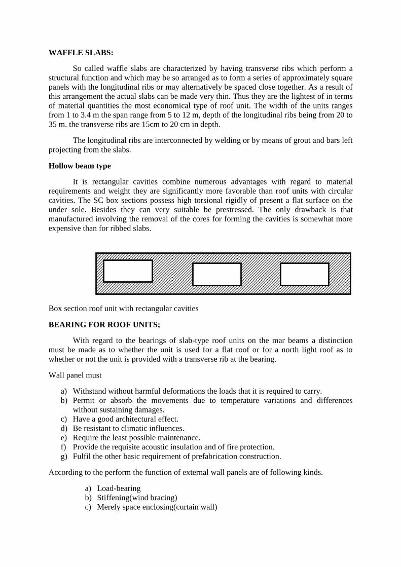
Hollow beam type
It is rectangular cavities combine numerous advantages with regard to material
requirements and weight they are significantly more favorable than roof units with circular
cavities. The SC box sections possess high torsional rigidly of present a flat surface on the
under sole. Besides they can very suitable be prestressed. The only drawback is that
manufactured involving the removal of the cores for forming the cavities is somewhat more
expensive than for ribbed slabs.
Box section roof unit with rectangular cavities
BEARING FOR ROOF UNITS;
With regard to the bearings of slab-type roof units on the mar beams a distinction
must be made as to whether the unit is used for a flat roof or for a north light roof as to
whether or not the unit is provided with a transverse rib at the bearing.
Wall panel must
a) Withstand without harmful deformations the loads that it is required to carry.
b) Permit or absorb the movements due to temperature variations and differences
without sustaining damages.
c) Have a good architectural effect.
d) Be resistant to climatic influences.
e) Require the least possible maintenance.
f) Provide the requisite acoustic insulation and of fire protection.
g) Fulfil the other basic requirement of prefabrication construction.
According to the perform the function of external wall panels are of following kinds.
a) Load-bearing
b) Stiffening(wind bracing)
c) Merely space enclosing(curtain wall)
The class design of wall panels depends on the requirements
a) Single layer solid panels consisting of one material Eg: light weight concrete
b) Multi- layer panels consisting of concrete and insulating materials.
c) Special section slabs, which may be either of single-layer or multi-layer
constructions(sandwich construction)
SHEAR WALL
Shear walls are vertical elements of the horizontal force resisting system. Shear walls
are constructed to counter the effects of lateral load acting on a structure. In residential
construction shear walls are straight external walls that typically form a box which provides
all of the lateral support for the building.
Importance of shear wall
When shear walls are designed and constructed property and they will have the
strength and stiffness to resist the horizontal forces. In building construction a rigid vertical
diaphragm capable of transferring lateral forces from exterior walls floors and roofs to the
ground foundation in a direction parallel to their planes.
Lateral forces caused by wind earthquake and uneven settlement loads. In addition to the
weight of structure and occupants create powerful twisting (torsion) forces. These forces can
literally tear (shear) a building apart. Reinforcing a frame by attaching or placing a rigid wall
inside it maintains that shape of the frame and prevents rotation at the joints shear walls are
especially important in high-rise building subjected to lateral wind and seismic forces.
In the last two decades shear walls became an important part of mid high rise residential
buildings. As part of an earthquake resistant building design these walls are placed in
building plans reducing lateral displacements under earthquake loads. So shear wall frame
structure are obtained.
Shear wall buildings are usually regular in plan and in elevation. However, in some buildings
lower floors are used for commercial purposes and the buildings are characterized with larger
plan dimensions at those floors.
Purpose of constructing shear walls
1. Shear walls are not only designed to resist gravity/vertical loads due to its self-weight
& other living moving loads), but they are also designed for lateral loads of
earthquakes/wind. The walls are structurally integrated with roofs/floors
(diaphragms) and other lateral
2. Shear wall structural systems are more stable because their supporting area (Total
cross sectional area of all shear walls) with reference to total plans area of building is
comparatively more, unlike in the case of RCC framed structures.
3. Walls have to resist the uplift forces caused by the pull of the wind walls have to
resist the shear forces that try to push the walls over walls have to resist the lateral
force of the wind that tries to push the walls in and pull them away from the building.
4. Walls floors and roofs to the ground foundation in a direction parallel to their planes.
Lateral forces caused by wind earthquake and uneven settlement loads. In addition to the
weight of structure and occupants create powerful twisting (torsion) forces. These forces can
literally tear (shear) a building apart. Reinforcing a frame by attaching or placing a rigid wall
inside it maintain the joints shear walls are especially important in high-rise building
subjected to lateral wind and seismic forces.
In the last two decades shear walls became as important part of mid high rise residential
buildings. As part of an earthquake resistant building design, these walls are placed in
building plans reducing lateral displacements under earthquake loads. So shear wall frame
structures are obtained.
Shear wall buildings are usually regular in plan and in elevation. However, in some
buildings lower floors are used for commercial purposes and the buildings are characterized
with larger plan dimensions at these floors.
Comparisons of shear wall with construction of conventional load bearing walls.
Load bearing masonry is very brittle material. Due to different kinds of stresses such
as shear, tensile..etc. Caused by the earthquakes the conventional unreinforced brick masonry
collapses instantly during the unpredictable and sudden earthquakes.
The RCC framed structures are slender. When compared to shear wall concept of box like
three-dimensional structures though it is possible to design the earthquake resistant RCC
frame it requires extra-ordinary skills at design detailing and construction levels. Which
cannot be anticipated in all types of construction projects?
On the other hand even moderately designed shear wall structures not only more stable, but
also comparatively quite ductile. In safety terms it means that during very severe earthquakes
they will not suddenly collapse causing death of people. They give enough indicative
warnings such as widening structural cracks yielding rods etc offering most precious moment
for people to run out off structures before they totally collapse.
For structural purposes we consider the exterior walls as the shear resisting walls. Forces
from the ceiling and roof diaphragms make their way to the outside along assumed paths
enter the walls and exit at the foundation.
Forces on shear wall
Shear wall resist two types of forces
1. Shear forces
2. Uplift forces
Shear Forces
Shear forces are generated in stationary buildings by accelerations resulting from
ground movement and by external forces like wind & waves. This action creates shear
forces throughout the height of the wall between the top and bottom shear wall
connections.
Uplift Forces
Uplift forces exist on shear walls because the horizontal forces are applied to the
top of the wall. These uplift forces try to lift up one end of the wall and push the other end
down. In some cases the uplift force is large enough to tip the wall over. Uplift forces are
greater on tall short walls uplift shear walls need hold down devices at each end when the
gravity loads cannot resist all of the uplift. The hold down device then provides the
necessary uplift resistance.
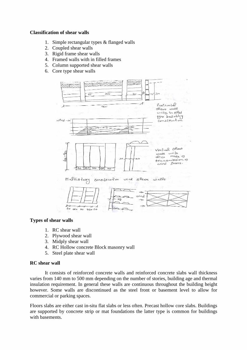
Classification of shear walls
1. Simple rectangular types & flanged walls
2. Coupled shear walls
3. Rigid frame shear walls
4. Framed walls with in filled frames
5. Column supported shear walls
6. Core type shear walls
Types of shear walls
1. RC shear wall
2. Plywood shear wall
3. Midply shear wall
4. RC Hollow concrete Block masonry wall
5. Steel plate shear wall
RC shear wall
It consists of reinforced concrete walls and reinforced concrete slabs wall thickness
varies from 140 mm to 500 mm depending on the number of stories, building age and thermal
insulation requirement. In general these walls are continuous throughout the building height
however. Some walls are discontinued as the steel front or basement level to allow for
commercial or parking spaces.
Floors slabs are either cast in-situ flat slabs or less often. Precast hollow core slabs. Buildings
are supported by concrete strip or mat foundations the latter type is common for buildings
with basements.

Ply wood shear wall
Plywood is the traditional material used in the construction of shear walls the creation
of pre-fabricated shear panels have made it possible to inject strong shear assemblies into
small walls that fall at either side of a opening in a shear wall plywood shear wall consist of
- Plywood to transfer shear forces
- Chords to resist tension/compression generated by the over turning
moments.
- Base connections to transfer shear to foundations
Midply shear wall
The midply shear wall is an improved timber shear wall that was developed by
redesigning the joints between shearing and finishing members. So, that the failure modes
observed in standard wall testing are virtually eliminated at lateral loads levels high enough
to cause failures in standard walls
RC Hollow concrete block masonry walls (RHCBM)
These walls are constructed by reinforcing the hollow concrete block masonry by
taking advantage of hollow spaces & shapes of the hollow blocks. It requires continuous steel
rods (reinforcement) both in the vertical & horizontal directions at structurally critical
locations of the wall panels packed with the fresh grout concrete in the hollow spaces of
masonry bocks.
RHCBC elements are designed both as load bearing walls for gravity loads and also as shear
walls for lateral seismic loads to safety withstand earthquakes.
Steel plate shear wall
In general steel plate shear wall system consists of a steel plate wall boundary
columns and horizontal floor beams. Together the steel plate wall and boundary columns act
as a vertical plate girder. The column act as flanges of the vertical plate girder and the steel
plates wall act as its web. The horizontal floor beams act more or less as transverse stiffeners
in a plate girder steel plate shear wall systems have been used in recent years in highly
seismic area to resist lateral loads.
Thus shear walls are one of the most effective building elements in resisting lateral forces
during earthquake. By constructing shear walls damages due to effect of lateral forces due to
earthquake and high winds can be minimized shear walls construction will provide larger
stiffness to the buildings there by reducing the damage to structure and its contents.
Hence it is preferable to have all these prefabricate approximately of some weight very near
to the lifting capacity of the equipment.
UNIT-III
Disuniting of Structures
The solution of problems connected with the transportation and placing of structures
demands as a rule their disuniting in to smaller members. One bay frames not exceeding, 40
tonnes in weight may represent an exception because the problems of their hoisting and
placing can be solved with the aid of modern available hoisting machines and equipment.
In spite of this framed are frequently disunited at their corners or points of minimum
moments into members to make the hoisting of these smaller members possible, using much
simpler equipment.
In general there is trend towards the use of larger members. This justified by more than one
reason. One is that the bearing of a certain moment can be solved more economically by
using one large girder instead of two or more smaller beams together having the same
capacities.
The table indicates the moment bearing capacity of the girder. While the
enlargements of the cross section lead to an 11 fold dead load, the moment bearing capacity
increased 80 fold. However with regard to the load bearing capacity, the moment bearing
capacity is not the unique .Decisive factor because the shear force that can be borne by a
cross section does not increase in the same ratio as does the moment.
In addition the hoisting of one large member as a rule, less expensive than that of 2 smaller
members having the same combined weight. It is a direct consequence of the following
circumstances:
The assembling of the lifting tackle, the transfer of the hoisting machine, the hoisting, placing
and plumbing must be done for each member separately, independently of its weight.
The disuniting into larger members means lower costs of hoisting and placing as well
as saving in joining costs.
In the first case the expenses of preparation and payments connected with the hire of
the equipment may be higher, but the work itself is much less.
Naturally, if plant prefabrication is practiced, the greatest size of precast members is
determined by the transportation and shipping cost.
But demands are not unlimited either. So, members whose weight would exceed 60
tons cannot be found even in structures of the largest power stations.
Nowadays, the hoisting capacity of derricks is 40 tons, while that of a pair of twinned-
a mast crane reaches 70 tons.
In this case the members should be as large as possible within the limits of the
available hoisting capacity.
(a) Systems consisting of linear members disunited at joints:
Disuniting at joints gives linear members. This means a great advantage and facility from the
view point of both manufacture and assembly.
The disadvantage of the system is that the joints are at the corners, ie at places where the
moments usually reach their maximal values, so the forming of the joints is difficult.

The quality of subsequent concreting executed in situ is only exceptionally and at readily
accessible places as good as the concrete quality of precast members. Therefore, the joints
must be over dimensioned.
(b) System for the prefabrication of entire rigid frame
The trend to lessen number of joints to precast larger members in one pieces loads to the
prefabrication of entire frames.
The construction arched trusses can be properly carried out in the horizontal position only.

Two &Three Hinged Structures
The prefabrication of larger arches in the horizontal position is found to be more economical.
Using this method the arches must be tilted up and this involves the solution of an additional
problem.
The construction of arched trusses can be properly carried out in the horizontal position only.
JOINT DEFORMATION
Joint deformation refers to how the joint behaves in regard to the far field stresses
FLEXIBILITY JOINT
Joint that holds two parts together so that one can swing relative to the other.
UNIT IV
JOINTS IN STRUCTURAL MEMBERS
One of the most intricate and most difficult problems to be solved in both design of
construction of structures assembled of prefabrication members is the joining.
It is highly important that the construction of the joints should be easy that
unavoidable smaller inaccuracies and deviations within dimensional tolerances should neither
influence the designed stresses in a detrimental manner nor cause is admissible changes in the
stress distribution of the structures.
The forming and construction of joints requires owing to their intricacy, great
increased control joints which cannot be inspected should be omitted.
When solving the problem of joints the properties of reinforced concrete must be
taken into consideration. This means in other words, that the design of the construction of the
joint should harmonize with the materials to be used. The properties of steel of timber are
quite different from those of concrete and reinforced concrete. Therefore joints similarly to
those used in timber and steel construction are generally not appropriate for the purpose.
Joints of reinforced concrete structures which should be omitted are shown
These joints have to be seen. This is a solution resembling a butt joint with splayed
table as used in timber construction. This doesn’t comply with the nature of the material of so
is not good for this purpose. The imitating a joint used in steel construction, is not appropriate
either. The steel structure like joint as seen in which the component structural parts are
welded to the reinforcement is also not sufficient adequate. The two halves of the steel
structure forming the main constituents of the joints have to be concrete into the ends of the
jointed. The slightest rotational displacement is sufficient to hinder the teeth to one another
and the placing of the pins.
The joints can be rigid hinge-like or shed rigid joints are adequate in addition to the
bearing the tensile, compressive of shear forces for resistance.
Design of class based an efficiency of the material used:
The plastic concrete can be used for the subsequent concrete of joints of the
fluid cement mortar cast or pressed into the gaps less part of their water during the setting
time of shrink, after setting the shrinkage of the insite concrete of mortar continue.
With respect to two phase of shrinkage same codes on reinforced concrete
construction permit only reduced stresses for a subsequent insite concrete of a mortar casting.
There are generally determined as a function of width of the joint on the gap to be concrete as
cast.
Joints must be designed of executed so that compensation for the allowed dimensional
tolerances is ensured. A relative displacement of the joined member should be impossible
even as a result of a blow or of any other unfavourable force effect. The length of the section
determined for the transmission of forces should be as short as possible but should excluded
any excess of the permissible stress.
The joints can be rigid hinge like or shed. Rigid joints are adequate in addition to the
bearing of tensile, compressive of shear forces for resisting to bending moments too. These

joints make relative displacement and relative relation impossible. Hinge like joints can
transmit forces passing through the hinge itself and also allow a certain motion and rotation.
Rigid joints are generally used for the junction of column to footings, but they can
also be applied for joining of individual groups with one another. The joints generally used in
the construction with precast members are usually hinge like. Their execution is simpler and
requires less working lime than rigid joints “shed joints” are only exceptionally used in
industrial construction of are justified for a long span only. These joints are chiefly used in
bridge construction for long span bridges depending on the necessity of insite concreting; two
kinds of joints can be distinguished.
a) Dry joints = joint accomplished by simple placing of two members on each
other of fasting.
b) Wet joints = joint require not only casting with cement mortar but also
subsequent concreting.
Joints for different structural connections:
Jointing of column to footing
Jointing of column to beam on top of column.
Jointing of column to beam at an intermediate functions.
Lengthening of columns.
Jointing of beams.
Forming of joints of arched structure.
Joining of joints f post tensioned structures.
Joining of precast to monolithic reinforced concrete structures.
(a) JOININNG COLUMNS TO FOOTING:
This joint is usually rigid but also can be hinge. A rigid joint can be made by placing
the column into a calyx of the footing or by using a welded joint. The figure shows the
three variations of this method.
Can be used for smaller.
For average.
For large footings
.
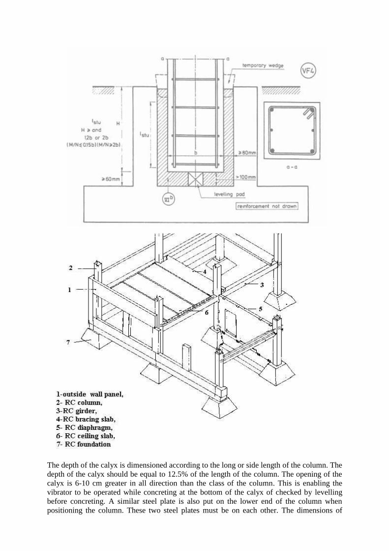
The depth of the calyx is dimensioned according to the long or side length of the column. The
depth of the calyx should be equal to 12.5% of the length of the column. The opening of the
calyx is 6-10 cm greater in all direction than the class of the column. This is enabling the
vibrator to be operated while concreting at the bottom of the calyx of checked by levelling
before concreting. A similar steel plate is also put on the lower end of the column when
positioning the column. These two steel plates must be on each other. The dimensions of
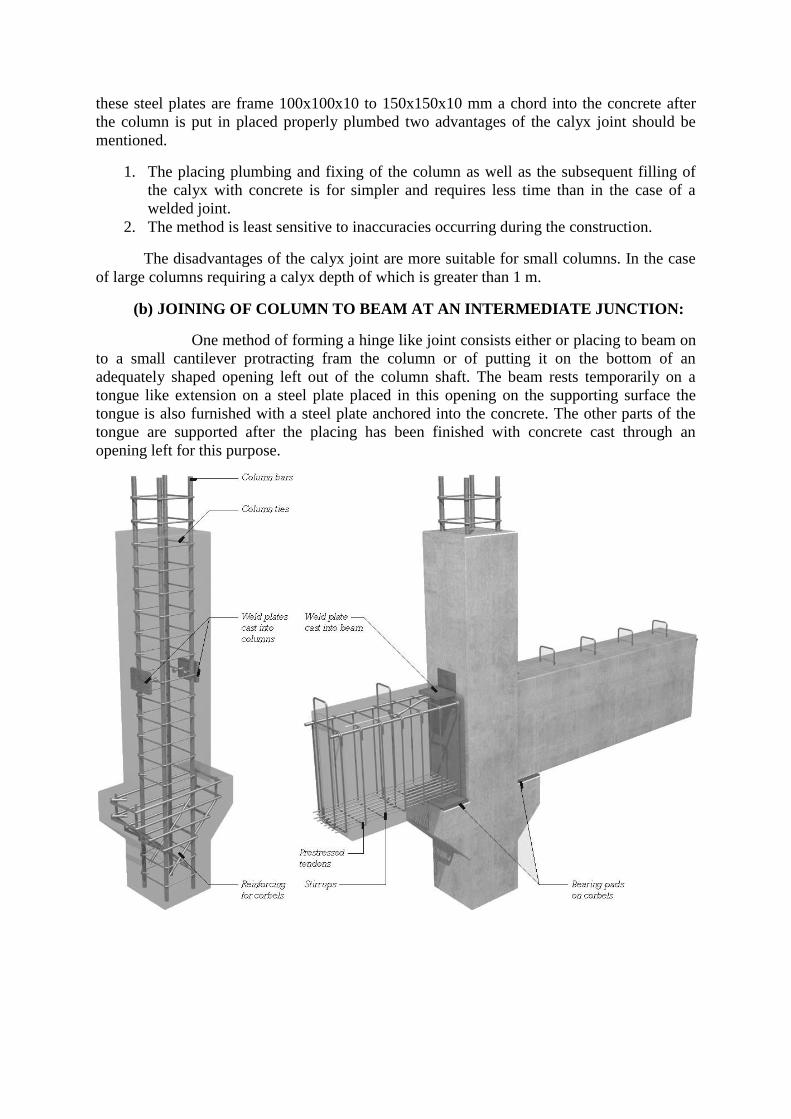
these steel plates are frame 100x100x10 to 150x150x10 mm a chord into the concrete after
the column is put in placed properly plumbed two advantages of the calyx joint should be
mentioned.
1. The placing plumbing and fixing of the column as well as the subsequent filling of
the calyx with concrete is for simpler and requires less time than in the case of a
welded joint.
2. The method is least sensitive to inaccuracies occurring during the construction.
The disadvantages of the calyx joint are more suitable for small columns. In the case
of large columns requiring a calyx depth of which is greater than 1 m.
(b) JOINING OF COLUMN TO BEAM AT AN INTERMEDIATE JUNCTION:
One method of forming a hinge like joint consists either or placing to beam on
to a small cantilever protracting fram the column or of putting it on the bottom of an
adequately shaped opening left out of the column shaft. The beam rests temporarily on a
tongue like extension on a steel plate placed in this opening on the supporting surface the
tongue is also furnished with a steel plate anchored into the concrete. The other parts of the
tongue are supported after the placing has been finished with concrete cast through an
opening left for this purpose.

Hinge like joining of girder to column:
1. Opening for casting.
2. Subsequent concreting.
3. Steel plate.
(c) LENGTHNING OF COLUMNS:
Columns are usually lengthened at floor levels. An intermediate lengthening
should be avoided it possible.
The lengthening of columns can be executed similarly to the joining with
footing, accordingly the upper columns rests on the lower ones by a tongue like extension.
The steel bars of the main reinforcement are joined by overlapping looped steel bars a
welding. There after the stirrups have to be placed of finally the joint must be concreted.

(d) JOINING OF BEAMS:
The functions of beams can be affected either by overlapping the protracting steel
bars or by welding them together.
Fig. shows the hinge like joint of purlins. In this method the whole shear must be
borm by both cantilevers (i.e.) by two separate structures therefore it is expedient to form this
joint at least for large girders.
The method illustrated in the fig presents a dry joint of beams which is called a bolted
front. The advantages of this joint are immediate bearing capacity.
(e) FORMING OF FUNCTIONS OF ARCHED STRUCTURES:
Precast arches are usually produced and assembled in the form of three hinged
structures. When the constant load has already been applied the centre joint is frequently
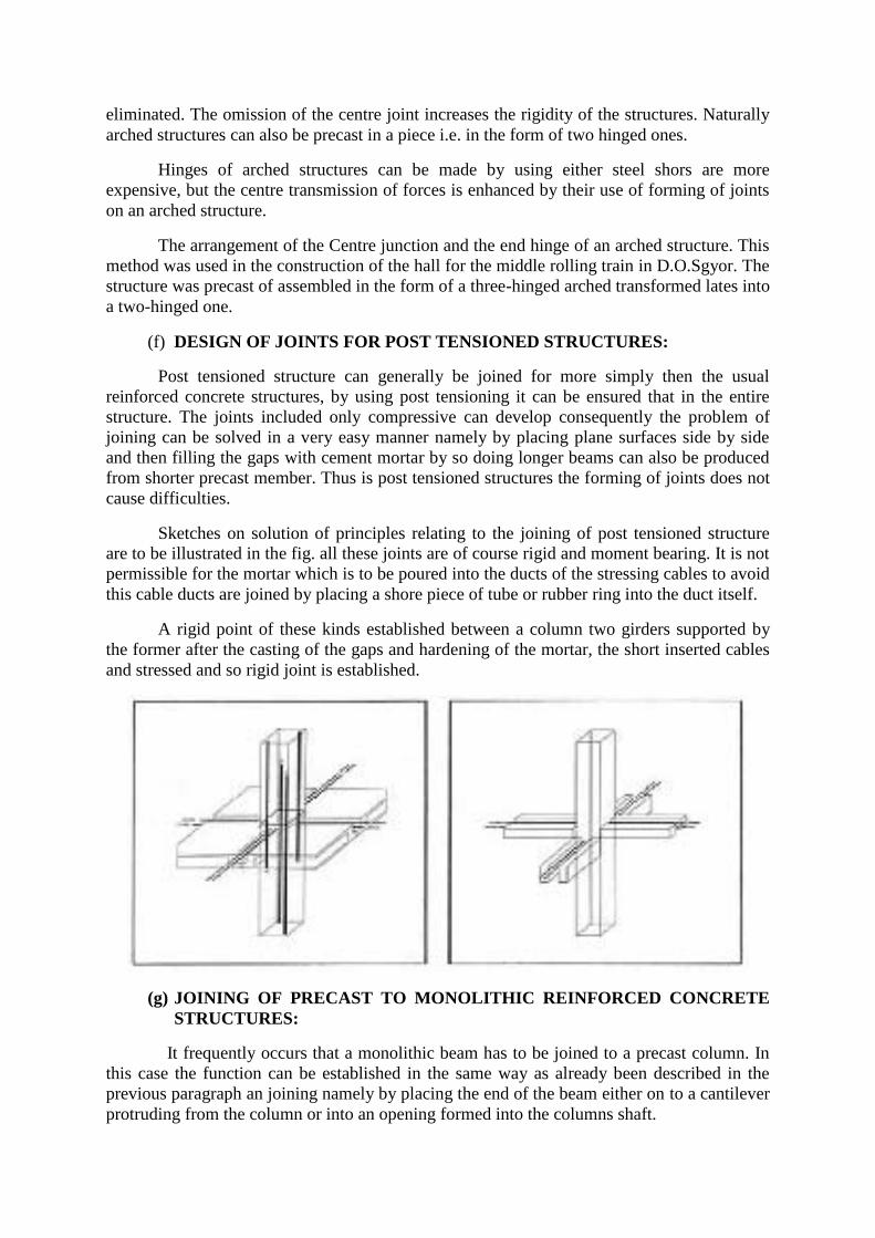
eliminated. The omission of the centre joint increases the rigidity of the structures. Naturally
arched structures can also be precast in a piece i.e. in the form of two hinged ones.
Hinges of arched structures can be made by using either steel shors are more
expensive, but the centre transmission of forces is enhanced by their use of forming of joints
on an arched structure.
The arrangement of the Centre junction and the end hinge of an arched structure. This
method was used in the construction of the hall for the middle rolling train in D.O.Sgyor. The
structure was precast of assembled in the form of a three-hinged arched transformed lates into
a two-hinged one.
(f) DESIGN OF JOINTS FOR POST TENSIONED STRUCTURES:
Post tensioned structure can generally be joined for more simply then the usual
reinforced concrete structures, by using post tensioning it can be ensured that in the entire
structure. The joints included only compressive can develop consequently the problem of
joining can be solved in a very easy manner namely by placing plane surfaces side by side
and then filling the gaps with cement mortar by so doing longer beams can also be produced
from shorter precast member. Thus is post tensioned structures the forming of joints does not
cause difficulties.
Sketches on solution of principles relating to the joining of post tensioned structure
are to be illustrated in the fig. all these joints are of course rigid and moment bearing. It is not
permissible for the mortar which is to be poured into the ducts of the stressing cables to avoid
this cable ducts are joined by placing a shore piece of tube or rubber ring into the duct itself.
A rigid point of these kinds established between a column two girders supported by
the former after the casting of the gaps and hardening of the mortar, the short inserted cables
and stressed and so rigid joint is established.
(g) JOINING OF PRECAST TO MONOLITHIC REINFORCED CONCRETE
STRUCTURES:
It frequently occurs that a monolithic beam has to be joined to a precast column. In
this case the function can be established in the same way as already been described in the
previous paragraph an joining namely by placing the end of the beam either on to a cantilever
protruding from the column or into an opening formed into the columns shaft.

When making the joint, first of all a 2.5 cm deep cavity is chiselled out of the siole of
the precast column. The bottom of this cavity should be roughened so as to attain a belter
band between the concrete of the monolithic beam and the precast column.
EXPANSION JOINT
An Expansion joint is an assembly designed to safely absorb the heat –induced expansion and
contraction of various construction material to absorb vibration or to allow movement due to
ground settlement or earthquakes they are commonly found between sections of sidewalks,
bridges, railway tracks, piping systems, and other structures.
EXPANSION JOINT DESIGN
A design specification shall be prepared for each expansion joint application. Prior to
writing the expansion joint design specification it is imperative that the system designer
complicity review the structural system layout and other items which may affect the
performance of a expansion joint particular attention shall be given to the following items the
system should be reviewed to determined the local and type of expansion joint which is most
suitable for the application. Both the EJMA standards and most reliable expansion joint
manufacturers. catalogs provide numerals examples to assist the user in this effort. The
availability of supporting structures of anchoring and guiding of the system and the direction
and magnitude of thermal moments to be absorbed must be consider when selecting the type
and location of the expansion joint.
CONVENTIONAL RUBBER EXPANSION JOINT
Expansion joints are designed to provide stress relief in piping system that are loaded by
thermal movements and mechanical vibration. To deal with the various forces on the joint
they require fiber reinforcement which guarantees both flexibility and strength. conventional
expansion joints are reinforced using prefabricated fiber pipes, the use of these fiber pipes
makes it impossible to control the orientation of the fiber on complex shape such as the below
of the expansion joint. In both case the inability to use the fiber in the optimal way leads to
the following disadvantages.
High material cost
More fiber needed then necessary
More rubber needed then necessary
Additional parts such as material reinforcement rings necessary with multiple bellows
Lower Performance
High rubber wall thickness and fiber pack make product less flexible
Undesired radial and axial expansion under pressure.
UNIT-V
DESIGN FOR ABNORMAL LOADS
PROGRESSIVE COLLAPSE
Progressive collapse occurs when a key member or member of a structure fail.
The isolated failure of this key member or section then initiates a sequence of events,
coursing failure of the entire structure
Progressive collapse
Progressive collapse can be defined as collapse of all or a large part of a structure by failure
or damage of a relatively small part of it. The general services administration (GSA,2003b)
offers a somewhat more specific description of the phenomenon progressive collapse is a
situation where local failure of a primary structural component leads to the collapse of
adjoining member which in turn leads to additional collapse.
It has also been suggested that the degree of progressivity in a collapse be defined as the ratio
of total collapsed area or volume to the area or volume damaged or destroyed directly by the
triggering event.
CODES AND STANDARDS
ASCE 7-02
The American society of civil engineers minimum design load for buildings and other
structure (ASCE,2002) has a section on general structure integrity that reads thus building
and other structures Shall be designed to sustain local damage with the structural system as
a whole remaining stable and not being damaged to an extent disproportionate to the original
local damage. This shall be achieved through an arrangement of the structural element that
provides stability to the entire structural system by transferring loads from any locally
damaged region to adjacent regions capable of resisting those loads without collapse .This
shall be accomplished by providing sufficient continuity , redundancy, or energy-dissipating
capacity (ductility) or a combination there of in a members of the structure clearly the
focused in the ASCE standard is on redundancy and alternate load paths overall other means
of avoiding susceptibility to disproportionate collapse. But the degree of redundancy is not
specified and the requirements or entirely threat -independent
ACI 318-02
The American concrete institution building code requirement for structural concrete
(ACI, 2002) include extensive requirement for structural integrity in the chapter on
reinforcing steel details. Though the commentary states that it is an intend of this section...to
improve 6 redundancy there is no explicit mention of redundancy or alternate load paths in
the code. The code provisions include a general statement that "In the detailing of
reinforcement and connections members of a structure shall be effectively tied together to
improve integrity of overall structure'' and many specific prescriptive requirements for
continuity of reinforcing steel and interconnection of components. There are additional
requirements for the typing together of precast structural components. None of the ACI
provisions are threat specific in anyway.

GSA PBS Facilities Standards 2003
The 2003 edition of the GSA'"s facilities standards for the public buildings service
(GSA, 2003) a retained the "Progressive Collapse'' heading from the 2000 edition.GSA
Progressive Collapse Guidelines 2003 GSA Progressive Collapse Analysis and Design
Guidelines for new federal of his buildings and major Modernization Projects (GSA,2003b)
begins with a process for determining whether a building is exempt from progressive collapse
considerations. Exemption is based on the type and size of the structure (for instance, any
building of over 10 stories is non-exempt) and is unrelated to the level of threat. Typical non-
exempt buildings in steel are concrete have to be shown by analysis to be able to tolerate
removal of one column of one-30 ft length of bearing wall without collapse. Considerable
detail is provided regarding the features of the analysis and the acceptance criteria.
GSA Progressive Collapse Guidelines 2003
The GSA Progressive collapse analysis and design guidelines for new federal office buildings
and major modernization projects(GSA,2003b) begins with a process for determining
whether a building is exempt from Progressive Collapse considerations. Exemption is based
on the type and size of the structure (for instance any building of over 10 stories is non-
exempt) and is unrelated to the level of threat. Typical non-exempt buildings in steel or
concrete have to be shown by analysis to be able to tolerate removal of one column or one-30
ft length of bearing wall without collapse. Considerable detail is provided regarding the
features of the analysis and the acceptance criteria.
METHODS OF AVOIDING DISPROPORTIONATE COLLAPSE
There are in general three alternate approaches to designing structures to reduce their
susceptibility to disproportionate collapse:
Redundancy or alternate load paths
Local Resistance
Interior or continuity
Redundancy or Alternate paths:
In this approach the structure is designed such that if any one component fails,
alternate paths are available for the load in that component and the general collapse does not
occur. This approach has the benefit of simplicity and directness in its most common
applications, design for redundancy requires that a building structure be able to tolerate loss
of any one column without collapse this is an objective easily understood performance
requirements the problem with the redundancy approach as typically practiced is that it does
not account for difference in vulnerability .Clearly one column redundancy when each
column is a W8x35 does not provide the same level of safety as when each column is a 2000
Ib/ft build up section. Indeed and explosion that cloud take out the 2000 Ib/ft column would
likely destroy several of the W8 columns making one column redundancy inadequate to
prevent collapse in that case. And ate codes and standards mandate redundancy do not
distinguish between two situation they threat every column as equally likely to be destroyed
in fact since it is generally much easier to design for redundancy of a small and lightly loaded
column redundancy requirements may have the unfortunate consequence of encouraging
design with small (and vulnerable) columns rather than fewer larger column. For safety
against deliberate attacks (as opposed to random accidence) this may be a step in wrong
direction.

Local Resistance
In this approach susceptibility to progressive /disproportionate collapse is reduced by
providing critical compoundence that might be subject to attack with additional resistance to
such attacks this requires some knowledge of the nature of potential attacks. And it is very
difficult to codify in a simple and object way.
Interconnection or continuity
This is strictly speaking not a third approach separate from redundancy and local
residence. But a means of improving either redundancy of or local residence (or both).Studies
of many recent building collapses have shown that the figure Could have been avoided or at
least reduced in scale, at fairly small additional cost if structural components had been
interconnect more effectively. This is the basis of the structural integrity requirement in the
ACI 318 specification (ACI 2002)