1600xp series series installation and operation manual product use and warranty restrictions the...
TRANSCRIPT

UninterrUptible power SyStem (UpS)
part # 60616-004march 2011
manufactured in the USA
© Copyright 2011 toSHibA international Corporation All rights reserved.
1600XP SERIESinStAllAtion And operAtion mAnUAl
Single pHASe - 3.6/6/8/10/14/18/22 kVA

1600Xp Series installation and operation manual

1600Xp Series installation and operation manual
UninterrUptible power SyStem (UpS)
inStAllAtion And operAtion mAnUAlSingle pHASe - 3.6/6/8/10/14/18/22 kVA
part # 60616-004march 2011
1600XP SERIES

1600Xp Series installation and operation manual
Product Use and Warranty Restrictions
the toshiba products listed in this document are intended for usage in general electronics applications (computer, personal equipment, office equipment, measuring equipment, industrial robotics, domestic appliances, etc.). these toshiba products are neither intended nor warranted for usage in equipment that requires extraordinarily high quality and/or reliability or where a malfunction or failure may cause loss of human life or bodily injury (Unintended Usage). Unintended Usage includes atomic energy control instruments, airplane or spaceship instruments, transportation instruments, traffic signal instruments, combustion control instruments, surgical operating room or life-support equipment, all types of safety devices, etc. Unintended Usage of toshiba products listed in this document shall be made at the customer’s own risk.
NOTICE
PLEASE INFORM TOSHIBA INTERNATIONAL CORPORATION OR AUTHORIZED REPRESENTATIVE IN CASE OF INCONSISTENCIES, OMISSIONS, OR QUESTIONS.
the instructions contained in this manual are not intended to cover all of the details or variations in equipment, or to provide for every possible contingency concerning installation, operation, or maintenance. Should further information be required or if problems arise which are not covered sufficiently, contact your Toshiba sales office.
the contents of this instruction manual shall not become a part of or modify any prior or existing agreement, commitment, or relationship. the sales contract contains the entire obligation of toshiba international Corporation UpS division. the warranty contained in the contract between the parties is the sole warranty of toshiba international Corporation UpS division and any statements contained herein do not create new warranties or modify the existing warranty.
Any electrical or mechanical modifications to this equipment without prior written consent of Toshiba International Corporation will void all warranties and may void the UL/CUL listing. Unauthorized modifications can also result in personal injury, loss of life, or destruction of the equipment.
QUALIFIED PERSONNEL ONLY
Qualified Personnel are those who have the skills and knowledge relating to the construction, installation, operation, and maintenance of the electrical equipment and have received safety training on the hazards involved (refer to the latest edition of nFpA 70e for additional safety requirements).

1600Xp Series installation and operation manual
UNINTERRUPTIBLE POWER SYSTEM (UPS)
please complete the following information and retain for your records.
Unless otherwise specified, the warranty period for the UpS or UpS part is 36 months from the shipment date (see toshiba international Corporation bill of lading).
Unless otherwise specified, the warranty period for a UPS battery is 24 months from the shipment date (see toshiba international Corporation bill of lading).
Job nUmber
model nUmber
SeriAl nUmber
AppliCAtion
SHipment dAte
inStAllAtion dAte
inSpeCted by

1600Xp Series installation and operation manual
Purpose
this manual provides information on how to safely install your toshiba international Corporation power electronics product. this manual includes a section of general safety instructions that describes the warning labels and symbols that are used throughout the manual. read the manual completely before installing, operating, or performing maintenance on this equipment.
this manual and the accompanying drawings should be considered a permanent part of the equipment and should be readily available for reference and review. dimensions shown in the manual are in metric and/or the english customary equivalent.
toshiba international Corporation reserves the right, without prior notice, to update information, make product changes, or discontinue any product or service identified in this publication.
toshiba is a registered trademark of the toshiba Corporation. All other product or trade references appearing in this manual are registered trademarks of their respective owners.
toshiba international Corporation shall not be liable for direct, indirect, special, or consequential damages resulting from the use of the information contained within this manual.
this manual is copyrighted. no part of this manual may be photocopied or reproduced in any form without the prior written consent of toshiba international Corporation.
© Copyright 2011 toshiba international CorporationAll rights reserved.printed in the U.S.A.
Toshiba Customer Support CenterContact the toshiba Customer Support Center for assistance with application information or for any problems that you may experience with your Uninterruptible power System (UpS).
Toshiba Customer Support Center 8 a.m. to 5 p.m. (CSt) - monday through FridayUSA toll Free (877) 867-8773tel (713) 466-0277Fax (713) 466-8773
you may also contact toshiba by writing to:
Toshiba International Corporation13131 west little york roadHouston, texas 77041-9990Attn: UpS product manager
For further information on toshiba products and services, please visit our website at:
www.toshiba.com/ind

i1600Xp Series installation and operation manual
Table of Contents
General Safety Instructions .............................................................................1Symbols ...................................................................................................1Signal words ...........................................................................................2regulatory Compliance Statement ..........................................................2
IMPORTANT SAFETY INSTRUCTIONS ...........................................................3QUAliFied perSonnel only ............................................................3
INSTRUCTIONS IMPORTANTES CONCERNANT LA SÉCURITÉ ..................4Product Description .........................................................................................5
Application and Use .................................................................................5output rating...........................................................................................5power backup..........................................................................................5power Conditioning..................................................................................5
Inspection/Storage/Disposal ...........................................................................6inspection ................................................................................................6Storage ....................................................................................................6disposal ...................................................................................................6
Installation Precautions ...................................................................................7Conductor Routing and Grounding ................................................................9Operating Precautions .....................................................................................9Equipment Warning Labels .............................................................................10UPS Connections .............................................................................................13
terminal block .......................................................................................13wire Size and tightening torque .............................................................14
Communication Interfaces ..............................................................................16UpS lAn Shutdown Signal operation ....................................................17rS-232C ..................................................................................................18remoteye iii network Card .....................................................................18
UPS Specifications ...........................................................................................19Operating the UPS ............................................................................................25
initial Startup .........................................................................................25battery backup time and discharge process .......................................26Starting/Stopping the UpS .......................................................................27battery recharging ..................................................................................28
Operating Modes ..............................................................................................29on-line (run operation) .......................................................................................29Static-bypass (Stop operation) ................................................................29battery backup (on batteries) .................................................................30

ii 1600Xp Series installation and operation manual
epo (emergency power off) Function ....................................................30Audible Alarm Functions ..........................................................................31
Display and Keys .............................................................................................32Front panel layout ..................................................................................32display manual Controls ..........................................................................32
LCD Touchscreen Layout ................................................................................33operating keys .......................................................................................34Status indicators ......................................................................................35light emitting diodes (led) ....................................................................35
Touchscreen Menu Tree ...................................................................................36Front panel layout ..................................................................................36
Screen Tab: Main ..............................................................................................37keypad Controls ......................................................................................38Screen: Security passwords & keypad ...................................................39
Screen Tab: Monitor .........................................................................................40Screen Tab: Settings ........................................................................................42
Settings parameters ................................................................................46records ..................................................................................................61System Fault messages ..........................................................................62System warning messages .....................................................................63System mode messages .........................................................................65System Status messages ........................................................................65
UPS Protection System....................................................................................67System protection Features ....................................................................67System protection Functions ..................................................................67
Preventive Maintenance/Parts Replacement .................................................68preventive maintenance ..........................................................................68Cleaning the touchscreen .......................................................................68parts replacement ..................................................................................69
Optional Receptacle Panel Installation Instructions .....................................69Optional MB (Maintenance Bypass) Units .....................................................71
internal maintenance bypass .........................................................................................71external maintenance bypass ........................................................................................72
External Layouts/Dimensions/Shipping Weights ..........................................73dimensional data ...................................................................................73electrical Conduit knock-out data ...........................................................73Unit and Shipping weights ......................................................................73
Index ..................................................................................................................77

11600Xp Series installation and operation manual
General Safety Instructions
do not attempt to transport, install, operate, maintain or dispose of this equipment until you have read and understood all of the product safety information provided in this manual.
Symbolsthe symbols listed below are used throughout this manual. when symbols are used in this manual they will include important safety information that must be carefully followed.
Safety Alert Symbol indicates that a potential personal injury hazard exists.
Prohibited Symbol indicates DO NOT take action.
Mandatory Symbol indicates that the following instruction is required.
Ground Symbol indicates the location of the equipment grounding conductor.
Electrical - Voltage & Shock Hazard Symbol indicates parts inside may cause electric shock.
Explosion Hazard Symbol indicates parts may explode.

2 1600Xp Series installation and operation manual
Signal Words
the signal words listed below are used throughout this manual. when the words dAnger, wArning, CAUtion and notiCe are used in this manual they will include important safety information that must be carefully followed.
Regulatory Compliance StatementFCC Class A Noticethis equipment has been tested and found to comply with the limits for a Class A digital device, pursuant to part 15 of the FCC rules. these limits are designed to provide reasonable protection against harmful interference when the equipment is operated in a commercial environment. this equipment generates, uses, and can radiate radio frequency energy, and if it is not installed and used in accordance with the instruction manual, it may cause harmful interference to radio communications. operation of this equipment in a residential area is likely to cause harmful interference, in which case the user will be requiredto correct the interference at his own expense.
this device complies with part 15 of the FCC rules. operation is subject to the following two conditions:this device may not cause harmful interference.1. this device must accept any interference received, including interference that may cause undesired 2. operation.
Notice: The FCC regulations provide that changes or modifications made to this device that are not approved by toshiba international Corporation may void the authority granted to the user by the FCC to operate this equipment.
EMC Directive Class A Notethis UpS is commercial in design and not intended for use at anytime in a residential environment.
the word DANGER in capital letters preceded by the safety alert symbol indicates that an imminently hazardous situation exists, and if not avoided will result in loss of life or serious injury to personnel.
the word WARNING in capital letters preceded by the safety alert symbol indicates that a potentially hazardous situation exists, and if not avoided may result in loss of life or serious injury to personnel.
the word CAUTION in capital letters preceded by the safety alert symbol indicates that a potentially hazardous situation exists, and if not avoided may result in minor or moderate injury.
the word NOTICE in capital letters without the safety alert symbol indicates a potentially hazardous situation exists, and if not avoided may result in equipment and property damage.
NOTICE
CAUTION
WARNING
DANGER

31600Xp Series installation and operation manual
IMPORTANT SAFETY INSTRUCTIONS
this manual contains important instructions that should be followed during the installation and maintenance of the UpS and its batteries.
Hardwired UpS units are not equipped with an over-current protection device nor an output disconnect for the AC output. A circuit breaker should be provided by the user between the UpS output and the load input. this device should be rated as follows:
240VAC RATING
3.6 kVA 6 kVA 8 kVA 10 kVA 14 kVA 18 kVA 22 kVA20 A 35 A 45 A 60 A 80 A 100 A 125 A
the nominal battery voltages for these models are as follows:
BATTERYVOLTAGE
3.6 kVA 6 kVA 8 kVA 10 kVA 14 kVA 18 kVA 22 kVA144 Vdc 216 Vdc 288 Vdc 288 Vdc 288 Vdc 288 Vdc 288 Vdc
Servicing of the batteries should only be performed by a qualified factory authorized representative who is knowledgeable about batteries and the required precautions. keep unauthorized personnel away from batteries. to arrange for battery replacement, contact your nearest factory authorized service center.
turn off, lockout, and tagout all equipment before connecting the power wiring to the equipment or 1. when performing maintenance.Hardwired UpS units are not equipped with an over-current protection device, nor do they have an 2. output disconnect for the AC output. therefore, a user-installed circuit breaker should be provided between the UpS output and the load input.the 3. maximum ambient operating temperature is 104 °F (40 °C).Access panels should only be removed by authorized Toshiba field Service personnel.4. UPS servicing should be performed by qualified Toshiba representatives only.5. Battery servicing should be performed by qualified Toshiba representatives only.6. Contact your toshiba authorized service center for battery replacement.7.
QUALIFIED PERSONNEL ONLYQualified personnel are those who have the skills and knowledge relating to the construction, installation, operation, and maintenance of the electrical equipment and have received safety training on the hazards involved (refer to the latest edition of nFpA 70e for additional safety requirements).
Qualified personnel shall:Have read the entire operation manual.1. be trained and authorized to safely energize, de-energize, ground, lockout and tag circuits and 2. equipment, and clear faults in accordance with established safety practices.be trained in the proper care and use of protective equipment such as safety shoes, rubber gloves, hard 3. hats, safety glasses, face shields, flash clothing, etc., in accordance with established safety practices.Be trained in rendering first aid.4. be knowledgeable about batteries and their required handling and maintenance precautions.5.
For further information about workplace safety visit www.osha.gov.

4 1600Xp Series installation and operation manual
misuse of this equipment may result in human injury and equipment damage. in no event will toshiba Corporation be responsible or liable for either indirect or consequential damage or injury that may result from the misuse of this equipment.
do not dispose of the battery module in a fire. The batteries inside may explode.
do not open or mutilate the batteries. released electrolyte is harmful to the eyes and skin and could also be toxic.
to be performed by Qualified Personnel Only:Verify that the UpS is off and that the power is disconnected from the power source.1. remove watches, rings or other metal objects.2. Use tools with insulated handles to prevent inadvertent shorts.3. wear rubber safety gloves and boots.4. do not place tools or any metal parts on top of batteries.5. determine if the battery is inadvertently grounded. if inadvertently grounded, remove source of 6. ground.
Contact with any part of a grounded battery can result in electrical shock.the likelihood of shock will be reduced if such grounds are removed prior to installation or maintenance.
INSTRUCTIONS IMPORTANTES CONCERNANT LA SÉCURITÉ
CONSERVER CES INSTRUCTIONSCette notice contient des instructions importantes concernant la sécurité.
ATTENTION Une battery peut présenter un risque de choc électrique, de brûlure par transfert d’ énergie.
ATTENTION l’ élimination des batteries est règlementèe. Consulter les codes locaux à cet effet.
WARNING
CAUTION
CAUTION
CAUTION

51600Xp Series installation and operation manual
Product DescriptionAn uninterruptible power system (UpS) is a system that is installed between the commercial power and the load equipment. the UpS provides steady AC output power during commercial power short-term blackouts or brownouts. this power is provided for a long enough time so that the load can be shut down in an orderly fashion. this prevents loss of data and possible damage to both hardware and software.during normal operation, the UpS uses commercial AC power. it absorbs all of the high voltage spikes and transients caused by switching and faults, and all of the common-mode and normal mode noise which is associated with commercial AC power. The UPS converts it all to flat DC power. From this power, the UPS charges its batteries and generates its own extremely high quality AC waveform output. the result of this process is maximum power conditioning and regulation.If the AC power supplied to the UPS drops below a specified voltage level, the unit’s batteries automatically begin supplying power instead of receiving it. this insures that the loads connected to the UpS continue to receive power with no interruption. when AC input power becomes available again, operation returns to normal. the unit’s batteries begin to recharge so they will be ready for the next power interruption.
Application and Usetoshiba 1600Xp Series of on-line UpS provides continuous computer-grade AC power in a compact, high performance, and energy efficient unit. The UPS unit assures safe and reliable operation of critical office equipment. All units feature an audible alarm which sounds if the battery voltage drops below a specified minimum during use. This is an additional aid to help protect valuable office data banks. All units allow for computer interfacing.
Output Ratingtoshiba 1600Xp Series (208/240V) offers UpS models with the following capacities:
MODEL Output Capacity @ 240 V Output kW @ .85PF 240 VUH3g2l036C61t 3.6 kVA 3.1 kwUH3g2l060C61t 6 kVA 5.1 kwUH3g2l080C61t 8 kVA 6.8 kwUH3g2l100C61t 10 kVA 8.5 kwUH3g2l140C61t 14 kVA 11.9 kwUH3g2l180C61t 18 kVA 15.3 kwUH3g2l220C61t* 22 kVA* 18.7 kw*
All models are roHS compliant with the batteries being exempt from the directive.*note: derate to 18.7 kVA (15.9 kw) for 50 Hz operation.
Power Backupwhen an electrical power failure occurs, the UpS’s internal batteries automatically supply back-up power to the load without interruption. For example, when used to support a computer, the UpS back-up assures enough additional time to complete the activity and store the data. this allows an orderly shutdown after a power failure has occurred.
Power Conditioningwhen commercial power is present, the UpS supplies conditioned power to the load while maintaining its batteries in a charged condition. the UpS protects against the normal, everyday problems associated with heavy use of raw commercial power, including power sags, surges, signal interference, and spikes. this protection keeps power-line problems from reaching your load, where they can cause equipment to operate erratically, or damage software and hardware.

6 1600Xp Series installation and operation manual
Inspection/Storage/Disposal
Inspectioninspect for shipping damage upon receipt of the UpS. Use caution when removing the unit from the pallet. refer to labels or documentation attached to packing material.
UnpackingCheck the unit for loose, broken, bent or otherwise damaged parts. if damage has occurred during shipping, keep all original crating and packing materials for return to the shipping agent. the warranty does not apply to damage incurred during shipping. Ensure that the rated capacity and the model number specified on the nameplate conform to the order specifications.
Storageduring periods of non-use, the following guidelines are recommended for storage.
Storage Preparationpower up the UpS and allow it to operate with no load for 24 hours to fully charge the 1. batteries.Stop the unit2. (see Stop operation on page 29).place the mCCb switch 3. (see page 65-66 for location) in the off position.
Storing ConditionsFor best results, store the UpS in the original shipping container and place on a wood •or metal pallet.Storage temperature: -4 – 104 °F (-20 – 40 °C).•the optimum storage temperature is 70 °F (21 °C). A higher ambient temperature will •require recharging more frequently during storage.
Avoid storage locations that:Are subject to extreme temperature changes or high • humidity.Are subject to high levels of dust or metal particles.•Are subject to excessive vibration.•Have inclined floor surfaces.•
Storage Maintenanceif stored at an ambient temperature less than 68 °F (20 °C), recharge the batteries every •9 months.if stored at an ambient temperature of 68 – 86 °F (20 – 30 °C), recharge the batteries •every 6 months.if stored at an ambient temperature of 86 – 104 °F (30 – 40 °C), recharge the batteries •every 3 months.
DisposalContact your local or state environmental agency for details on disposal of electrical components and packaging in your particular area.It is illegal to dump lead-acid batteries in landfills or dispose of improperly.please help our earth by contacting the environmental protection agencies in your area, the battery manufacturer, or call toshiba toll-free at (877) 867-8773 for more information about recycling.

71600Xp Series installation and operation manual
Installation Precautions
NOTICEobserve the following environmental restrictions:1.
install the unit in a well-ventilated location; allow at least 4 inches (10 cm) on all sides for air •ventilation and for maintenance.Install the unit where the ambient temperature is within the range specified on• pages 20 and 23.do not install the UpS in areas that are subject to high humidity.•do not install the UpS in areas that allow exposure to direct sunlight.•do not install the UpS in areas that allow exposure to high levels of airborne dust, metal •particles, or flammable gases.do not install the UpS in areas near sources of electrical noise. ensuring a proper earth • ground will reduce the effects of electrical noise and will reduce the potential for electrical shock.DO NOT install the UPS in areas that would allow fluids or any foreign object to get inside the •UpS.
UpS is intended for permanent installation only. install the unit in a stable, level and upright position 2. that is free of excessive vibration. Allow at least 4 inches (100 mm) clearance on all sides of the ups 3. for air ventilation.
Follow the instructions on the unpacking label affixed to the exterior of the UPS. 4.
WARNINGThis unit contains sealed lead acid batteries.lack of preventative maintenance could resultin batteries exploding and emitting gasses and/orflame. Annual preventative maintenance must beperformed by an authorized, trained technician.
WARNINGCRITICAL FUSE SIZINGincorrect fu se replacem ent sizemay result in fire or inadeq uateequ ipm ent protection.re pla ce only with same t ypeand rating of fuse.
49455 SHEET
CAUtion/Attention
do not disconnectwhile unit isoperatingon battery power.nes pas debranchersous charge.
48524 SHEET
risk of electric sho ck. do not re move cover. . refer servic ing to qualified se rvice personnel.
no USer SerViCeAble pArtSinSide
to reduce the risk of fire or electric shock, install in a te mperature and hum id ity controlled indoor area free of conduc tive conta mina nts.
en c as utilisa tion en atm osphe re controlee. Consulter la notice technique.
note: Service pe rsonnel only.Haza rd ous live p arts inside the UpS are energized from the ba ttery supp lyeven when the input AC power is d isconnected.
Capac itors store hazard ous energ y. do not rem ove cover until 5 minutes after d isconnecting all sources of supp ly.
battery b ackup time, which wa s factory-set at a pred etermined level,decreases gradually b etween service period s. the ba tterie s should b ereplaced every three yea rs after the last servic ing, the da te of which iswritten on the id plate lo cated on the rea r side of the UpS unit, or in the boxes b elow.
date of last ba ttery cha rge:
WARNING
CAUTIONDo not insert battery trays with the power off !
This unit is designed for hot changeable batteries!When installing batteries, the UPS must be in theonline or bypass mode. Contact ToshibaInternational Corporation for further details.
6041
2
pn 51727
EXTERNAL BATTERY CABINETThe battery cabinet must have a nominal battery voltage of 288VDC.
WARNING
DANGER/ATTENTIONrisk of electrical shock. do n ot touch u nin su lat edbatt ery terminals. batter ies sh ould be serviced b yqua lified service repre se ntative only. miswiring ofbatt ery could result in ele ctrcal sh ock a nd/or fire.
risque de choc electrique . le circuit des ba tteriesnest pa s e so led e secteur. le s cosses des ba tteriespeu ven t prese nter une te nsion dange reu se partrapport a la terre . Ve rifier avan t de to uch er.
DANGERbatte ry fuse is alwayslive. r isk of ele ctr ica lshock. Ch eck fu sevoltage an d discon nectexternal batte riesbefo re cha nging fuse.
48518 SHEET
fig 1
fig 2
1
2
3
Unpacking instructionsp/n 48537
typeForm
oUtpUt
mFd. in U.S.A. From Foreign And domeStiC ComponentS
HoUSton, teXAS
UninterrUptible power SUpply
inpUt
SeriAl no.pn 60381
LISTEDPOWERSUPPLY27E5
C US
epo
14 15 16 17
epo
1
epo
2
rem
ote
remote
1
l1 l2 g X1 X2
208V
120V 120V
208/240V
oUtpUtinpUt
n X3 g 208V
USe Copper 90 CondUCtorS only. reFer to inStrUCtion mAnUAl regArding tigHtening torQUe oF terminAl bloCkS. FACtory wired For 2 08V inpUt.
Com
2 3 4 5 6 7 8 11 12 13
240V
240V
rem
ote
JUmpe r Sel eCtion5080
2
right
minimum 4 in. (100 mm)
Clearance all sides
Front
rear
left

8 1600Xp Series installation and operation manual
once the installation is complete, use a 3/4 inch wrench to screw down the UpS leveling feet located 5. next to the four casters, until the unit is no longer resting on the casters.the UpS generates and can radiate radio-frequency energy during operation. Although rFi noise 6. filters are installed inside of the unit, there is no guarantee that the UPS will not influence some sensitive devices that are operating near by. if such interference is experienced, the UpS should be installed farther away from the affected equipment and/or powered from a different source than that of the affected equipment.
WARNING
THE METAL OF CONDUIT IS NOT AN ACCEPTABLE GROUND.
it is the responsibility of the installer of this equipment to provide a suitable disconnect for the Control 7. panel supplying power to this equipment.
this disconnect must:be suitable for the Voltage and Full load Ampere rating of all downstream equipment supplied by the panel;the supply disconnecting device shall be one of the following types:
Switch-disconnector, with or without fuses, in accordance with ieC 60947-3, utilization •category AC-23b or dC-23bAs above, except one that has an auxiliary contact that in all cases causes switching devices •to break the load circuit before the opening of the main contacts of the disconnector.A circuit breaker suitable as an isolation device per ieC 60947-2•Any other switching device in accordance with an ieC product standard that also meets the •isolation requirements of ieC 60947-1 and is appropriate for on-load switching of motors or other inductive loads;
be approved for use as a disconnect for the country in which this equipment is installed.be provided with a lock out tag out capability in the off (down) position.
Allow 5 minutes after power is removed for internal capacitors to fully discharge before attempting 8. to service the unit.The user should provide output over-current protection for hardwired UPS systems. See Specifications 9. section on pages 19 and 22 for the device rating.After ensuring that all power sources are turned off and isolated in accordance with established 10. lockout/tagout procedures, connect the power source wiring of the correct voltage to the input terminals of the UpS.the end user must supply suitable strain relief for the power cord and the cord must extend a 11. distance of 1/2 diameter beyond the clamp.Connect the output terminals of the UpS to the load in line with local wiring regulations. Size the 12. branch circuit conductors in accordance with neC table 310.16.

91600Xp Series installation and operation manual
Conductor Routing and GroundingUse separate metal conduits for routing the input power, output power, and control circuits.1. Follow the wire size and tightening torque specifications listed on page 14.2. Always ground the unit to reduce the potential for electrical shock and to help reduce electrical 3. noise.A separate ground cable should be run inside the conduit with the input power, output power, and 4. control circuits.
WARNING
THE METAL OF CONDUIT IS NOT AN ACCEPTABLE GROUND.
Operating Precautions
the UpS should not be powered up until the entire operation manual has been read.1. the voltage of the input power source must be within the range of +10% to -30% of the rated 2. input voltage. the input frequency must be within the rated input frequency range. Voltages and frequencies outside of the permissible range may activate the internal protection devices.the UpS should not be used with a load that has a rated input that is greater than the rated output 3. of the UpS.
4. do not use the UpS to provide power to motors that require high starting current or with motors that require a long starting time, such as vacuum cleaners and machine tools (oversizing the UpS for lock rotor current would be required).do not insert metal objects or combustible materials in the 5. ventilation slots of the UpS.do not place, hang, or paste any objects on the exterior surfaces of the UpS.6. the capacitors of the UpS maintain a residual charge for a while after turning the UpS off. the 7. required discharge time for each UpS typeform is provided via a cabinet label and a CHARGE LED. wait for at least the minimum time indicated on the label and ensure that the CHARGE LED has gone out before opening the door of the UpS once the UpS power has been turned off.do not attempt to disassemble, modify, or repair the UpS. repairs and servicing should only be 8. performed by toshiba Field Service personnel.do not remove any covers of the UpS when the power is on.9. turn the power on only after installing All of the covers.10. if the UpS should emit smoke, produce an unusual odor, or make sound, turn the power off 11. immediately.the heat sink and other components may become extremely hot to the touch. Allow the unit to cool 12. before touching these items.Changing/replacing the UPS Batteries should only be performed by Toshiba field service 13. personnel.

10 1600Xp Series installation and operation manual
14. Warning signs should be placed on or near the load as a notification that the load is being powered by the UpS.
15. Additional warnings and notifications shall be posted at the equipment installation location as deemed required by Qualified Personnel.
when operating in the inverter mode, placing the breaker in the OFF position will switch the UpS to the battery backup mode. the output of the UpS will continue uninterrupted to the load. the unit must be in the bypass mode at the time that the breaker is placed in the OFF position for the UpS to shutdown power to the load.
Equipment Warning Labels
the following pages show examples of warning labels that may be attached to either the interior or ex-terior of the UpS. do not remove or cover any of the labels. if the labels are damaged or if additional labels are required, contact your equipment representative for additional labels.
these labels are placed to provide useful information or to indicate an imminently hazardous situation that may result in severe equipment/property damage, serious injury, or loss of life if instructions are not followed.
WARNING

111600Xp Series installation and operation manual
p/n 48518 – battery terminals can deliver dangerous electrical shock. Service by qualified service representatives only.
WARNINGThis unit contains sealed lead acid batteries.lack of preventative maintenance could resultin batteries exploding and emitting gasses and/orflame. Annual preventative maintenance must beperformed by an authorized, trained technician.
WARNINGCRITICAL FUSE SIZINGincorrect fu se replacem ent sizemay result in fire or inadeq uateequ ipm ent protection.re pla ce only with same t ypeand rating of fuse.
49455 SHEET
CAUtion/Attention
do not disconnectwhile unit isoperatingon battery power.nes pas debranchersous charge.
48524 SHEET
risk of electric sho ck. do not re move cover. . refer servic ing to qualified se rvice personnel.
no USer SerViCeAble pArtSinSide
to reduce the risk of fire or electric shock, install in a te mperature and hum id ity controlled indoor area free of conduc tive conta mina nts.
en c as utilisa tion en atm osphe re controlee. Consulter la notice technique.
note: Service pe rsonnel only.Haza rd ous live p arts inside the UpS are energized from the ba ttery supp lyeven when the input AC power is d isconnected.
Capac itors store hazard ous energ y. do not rem ove cover until 5 minutes after d isconnecting all sources of supp ly.
battery b ackup time, which wa s factory-set at a pred etermined level,decreases gradually b etween service period s. the ba tterie s should b ereplaced every three yea rs after the last servic ing, the da te of which iswritten on the id plate lo cated on the rea r side of the UpS unit, or in the boxes b elow.
date of last ba ttery cha rge:
WARNING
CAUTIONDo not insert battery trays with the power off !
This unit is designed for hot changeable batteries!When installing batteries, the UPS must be in theonline or bypass mode. Contact ToshibaInternational Corporation for further details.
6041
2
pn 51727
EXTERNAL BATTERY CABINETThe battery cabinet must have a nominal battery voltage of 288VDC.
WARNING
DANGER/ATTENTIONrisk of electrical shock. do n ot touch u nin su lat edbatt ery terminals. batter ies sh ould be serviced b yqua lified service repre se ntative only. miswiring ofbatt ery could result in ele ctrcal sh ock a nd/or fire.
risque de choc electrique . le circuit des ba tteriesnest pa s e so led e secteur. le s cosses des ba tteriespeu ven t prese nter une te nsion dange reu se partrapport a la terre . Ve rifier avan t de to uch er.
DANGERbatte ry fuse is alwayslive. r isk of ele ctr ica lshock. Ch eck fu sevoltage an d discon nectexternal batte riesbefo re cha nging fuse.
48518 SHEET
fig 1
fig 2
1
2
3
Unpacking instructionsp/n 48537
typeForm
oUtpUt
mFd. in U.S.A. From Foreign And domeStiC ComponentS
HoUSton, teXAS
UninterrUptible power SUpply
inpUt
SeriAl no.pn 60381
LISTEDPOWERSUPPLY27E5
C US
epo
14 15 16 17
epo
1
epo
2
rem
ote
remote
1
l1 l2 g X1 X2
208V
120V 120V
208/240V
oUtpUtinpUt
n X3 g 208V
USe Copper 90 CondUCtorS only. reFer to inStrUCtion mAnUAl regArding tigHtening torQUe oF terminAl bloCkS. FACtory wired For 2 08V inpUt.
Com
2 3 4 5 6 7 8 11 12 13
240V
240V
rem
ote
JUmpe r Sel eCtion5080
2
p/n 49455 – UpS batteries require an-nual preventative maintenance. Failure to perform regular maintenance could result in batteries exploding, or emitting gasses or flame.
WARNINGThis unit contains sealed lead acid batteries.lack of preventative maintenance could resultin batteries exploding and emitting gasses and/orflame. Annual preventative maintenance must beperformed by an authorized, trained technician.
WARNINGCRITICAL FUSE SIZINGincorrect fu se replacem ent sizemay result in fire or inadeq uateequ ipm ent protection.re pla ce only with same t ypeand rating of fuse.
49455 SHEET
CAUtion/Attention
do not disconnectwhile unit isoperatingon battery power.nes pas debranchersous charge.
48524 SHEET
risk of electric sho ck. do not re move cover. . refer servic ing to qualified se rvice personnel.
no USer SerViCeAble pArtSinSide
to reduce the risk of fire or electric shock, install in a te mperature and hum id ity controlled indoor area free of conduc tive conta mina nts.
en c as utilisa tion en atm osphe re controlee. Consulter la notice technique.
note: Service pe rsonnel only.Haza rd ous live p arts inside the UpS are energized from the ba ttery supp lyeven when the input AC power is d isconnected.
Capac itors store hazard ous energ y. do not rem ove cover until 5 minutes after d isconnecting all sources of supp ly.
battery b ackup time, which wa s factory-set at a pred etermined level,decreases gradually b etween service period s. the ba tterie s should b ereplaced every three yea rs after the last servic ing, the da te of which iswritten on the id plate lo cated on the rea r side of the UpS unit, or in the boxes b elow.
date of last ba ttery cha rge:
WARNING
CAUTIONDo not insert battery trays with the power off !
This unit is designed for hot changeable batteries!When installing batteries, the UPS must be in theonline or bypass mode. Contact ToshibaInternational Corporation for further details.
6041
2
pn 51727
EXTERNAL BATTERY CABINETThe battery cabinet must have a nominal battery voltage of 288VDC.
WARNING
DANGER/ATTENTIONrisk of electrical shock. do n ot touch u nin su lat edbatt ery terminals. batter ies sh ould be serviced b yqua lified service repre se ntative only. miswiring ofbatt ery could result in ele ctrcal sh ock a nd/or fire.
risque de choc electrique . le circuit des ba tteriesnest pa s e so led e secteur. le s cosses des ba tteriespeu ven t prese nter une te nsion dange reu se partrapport a la terre . Ve rifier avan t de to uch er.
DANGERbatte ry fuse is alwayslive. r isk of ele ctr ica lshock. Ch eck fu sevoltage an d discon nectexternal batte riesbefo re cha nging fuse.
48518 SHEET
fig 1
fig 2
1
2
3
Unpacking instructionsp/n 48537
typeForm
oUtpUt
mFd. in U.S.A. From Foreign And domeStiC ComponentS
HoUSton, teXAS
UninterrUptible power SUpply
inpUt
SeriAl no.pn 60381
LISTEDPOWERSUPPLY27E5
C US
epo
14 15 16 17
epo
1
epo
2
rem
ote
remote
1
l1 l2 g X1 X2
208V
120V 120V
208/240V
oUtpUtinpUt
n X3 g 208V
USe Copper 90 CondUCtorS only. reFer to inStrUCtion mAnUAl regArding tigHtening torQUe oF terminAl bloCkS. FACtory wired For 2 08V inpUt.
Com
2 3 4 5 6 7 8 11 12 13
240V
240V
rem
ote
JUmpe r Sel eCtion5080
2
p/n 49455 – replace Fuse only with one of same type and range. incorrect fuse size may result in equipment damage.
WARNINGThis unit contains sealed lead acid batteries.lack of preventative maintenance could resultin batteries exploding and emitting gasses and/orflame. Annual preventative maintenance must beperformed by an authorized, trained technician.
WARNINGCRITICAL FUSE SIZINGincorrect fu se replacem ent sizemay result in fire or inadeq uateequ ipm ent protection.re pla ce only with same t ypeand rating of fuse.
49455 SHEET
CAUtion/Attention
do not disconnectwhile unit isoperatingon battery power.nes pas debranchersous charge.
48524 SHEET
risk of electric sho ck. do not re move cover. . refer servic ing to qualified se rvice personnel.
no USer SerViCeAble pArtSinSide
to reduce the risk of fire or electric shock, install in a te mperature and hum id ity controlled indoor area free of conduc tive conta mina nts.
en c as utilisa tion en atm osphe re controlee. Consulter la notice technique.
note: Service pe rsonnel only.Haza rd ous live p arts inside the UpS are energized from the ba ttery supp lyeven when the input AC power is d isconnected.
Capac itors store hazard ous energ y. do not rem ove cover until 5 minutes after d isconnecting all sources of supp ly.
battery b ackup time, which wa s factory-set at a pred etermined level,decreases gradually b etween service period s. the ba tterie s should b ereplaced every three yea rs after the last servic ing, the da te of which iswritten on the id plate lo cated on the rea r side of the UpS unit, or in the boxes b elow.
date of last ba ttery cha rge:
WARNING
CAUTIONDo not insert battery trays with the power off !
This unit is designed for hot changeable batteries!When installing batteries, the UPS must be in theonline or bypass mode. Contact ToshibaInternational Corporation for further details.
6041
2
pn 51727
EXTERNAL BATTERY CABINETThe battery cabinet must have a nominal battery voltage of 288VDC.
WARNING
DANGER/ATTENTIONrisk of electrical shock. do n ot touch u nin su lat edbatt ery terminals. batter ies sh ould be serviced b yqua lified service repre se ntative only. miswiring ofbatt ery could result in ele ctrcal sh ock a nd/or fire.
risque de choc electrique . le circuit des ba tteriesnest pa s e so led e secteur. le s cosses des ba tteriespeu ven t prese nter une te nsion dange reu se partrapport a la terre . Ve rifier avan t de to uch er.
DANGERbatte ry fuse is alwayslive. r isk of ele ctr ica lshock. Ch eck fu sevoltage an d discon nectexternal batte riesbefo re cha nging fuse.
48518 SHEET
fig 1
fig 2
1
2
3
Unpacking instructionsp/n 48537
typeForm
oUtpUt
mFd. in U.S.A. From Foreign And domeStiC ComponentS
HoUSton, teXAS
UninterrUptible power SUpply
inpUt
SeriAl no.pn 60381
LISTEDPOWERSUPPLY27E5
C US
epo
14 15 16 17
epo
1
epo
2
rem
ote
remote
1
l1 l2 g X1 X2
208V
120V 120V
208/240V
oUtpUtinpUt
n X3 g 208V
USe Copper 90 CondUCtorS only. reFer to inStrUCtion mAnUAl regArding tigHtening torQUe oF terminAl bloCkS. FACtory wired For 2 08V inpUt.
Com
2 3 4 5 6 7 8 11 12 13
240V
240V
rem
ote
JUmpe r Sel eCtion5080
2
Safety label explanations
p/n 63094 – external warning sign. Unit contains potentially dangerous voltages. • read the instruction manual before operating. • there are no user serviceable parts inside. • Refer service to qualified personnel.do not open the cover while power is applied, • or within five minutes after removal of power.potentially hazardous leakage current may • exist. ensure the grounding is connected before connecting the utility power..

12 1600Xp Series installation and operation manual
1
L1
(L*)
2
L2
(N*)
3
G
4
X1
5
X2
6
N
(0V*)
7
X3
8
G
11
208V
12
COM
13
240V
14
EPO1
15
EPO2
16
REMOTE
17
REMOTE
USE�COPPER�90 CONDUCTORS�ONLY.�REFER�TO�INSTRUCTION�MANUAL�REGARDING�TORQUE�OF�TERMINAL�BLOCKS.�FACTORY�WIRED�FOR�208V�INPUT.o
208/240V 208V
120V
240V
120VINPUT�VOLTAGE
JUMPER�SELECTION
EPO REMOTE
INPUT OUTPUT (�*)�FOR�SINGLE�HOT�WIRE
p/n63093 - power terminal label
p/n 63109 – there are no user-serviceable parts behind cover. Wait five minutes after disconnect-ing the UpS to allow the internal capacitors to discharge completely.
date of last recorded battery change.
p/n 51727 – external battery Cabinet Con-nection, nominal battery Cabinet Voltage of 288VdC required.

131600Xp Series installation and operation manual
UPS Connections
Terminal Block the following illustration is a detail view of the terminal block and wiring connections used for 208/240 volt units (see pages 65-66 for terminal block location).
* – if only one input line is hot, connect hot line to terminal 1 (l), and connect the neutral line to terminal 2 (n).
note 1 – if AC input power is 208 Vac rated, short terminals 11 and 12 with a jumper wire. do not jumper terminal 13 to 12 or 11. Factory Setting is 208Vac. Use the jumper wire provided by Toshiba. DO NOT add any additional jumpers.
note 2 – if AC input power is 240 Vac rated, short terminals 12 and 13 with a jumper wire. do not jumper terminal 11 to 12 or 13. Use the jumper wire provided by Toshiba. DO NOT add any additional jumpers.
240V208/240 Vin
REMOTE1208 EPO2EPO1 REMOTE2COM 240gX31
l2 (n*) g X1 X2 n (0V)
2 3 12 1413 158765 114 16 17l1 (l*)
120 V
240 V
120 V
208 V208V
Jumper selection See notes 1&2
inpUt oUtpUt

14 1600Xp Series installation and operation manual
Wire Size and Tightening TorqueUse the following table to select the recommended wire size and terminal lug tightening torque for i/o wire connections. Use 90 °C copper conductors for all input, output, and ground wiring.
Item Terminal Number
Cable Size - AWG Tightening Torque
lb.-in. (N•m)3.6 kVA 6 kVA 8 kVA 10 kVA 14-18 kVA 22 kVA
AC input lines 1 and 2 10 (8) 8 (8) 8 (1/0) 6 (1/0) 4 (1/0) 1 (1/0) 14.2 (1.56)
AC output lines 4, 5, and 7 12 (8) 10 (8) 8 (1/0) 6 (1/0) 4 (1/0) 1 (1/0) 14.2 (1.56)
AC output neutral 6 12 (8) 10 (8) 8 (1/0) 6 (1/0) 4 (1/0)) 1 (1/0) 14.2 (1.56)
ground 3 and 8 12 (8) 10 (8) 8 (1/0) 6 (1/0) 4 (1/0)) 1 (1/0) 14.2 (1.56)
epo Switch 14 and 15 16 16 16 16 16 16 9.0 (0.99)remote Switch 16 and 17 16 16 16 16 16 16 9.0 (0.99)
note: wire size is presented as the recommended size followed by a bold number in () that is the maximum wire size the terminal block can accommodate. See page 64 for knock-out hole sizes on the back of each model.

151600Xp Series installation and operation manual
Optional Battery Cabinet Connectionsoptional external battery cabinets can be used to extend the backup time of the UpS beyond that available with the internal batteries. the external battery cabinets connect to the UpS via Anderson-style connectors.
mCCb(battery Cabinetmain Circuitbreaker)
UPS Model Battery Cabinet MCCB Capacity
3.6, 6 kVA 50 A8, 10, 14, 18, 22 kVA 100 A
See the applicable battery cabinet manual for additional details.

16 1600Xp Series installation and operation manual
Communication Interfaces
Remote Contactsthe remote contacts interface is provided as a set of solid state switching devices. the switches are available through a db9 male connector on the rear of the UpS. the following chart shows the pin assignment for each signal.
MAxIMUM CURRENT CARRYING CAPACITYOF THE SWITCH
DB9 MALE CONNECTOR OUTLINE (FACING CONNECTOR)
Voltage Current48 Vdc peak 70 mA peak30 Vac rms
(42 Vac peak)50 mA rms
(70 mA peak)
Pin Signal Function Logic In the UPS
1 Fault Signal Closed when fault detected
2 UpS stop common backup stop when the level changes from low (-3 to -15 V) to High (+3 to +15 V)3 UpS stop signal input
4 normal input power supply Closed with normal supply power
5 Signal common Common signal return
6 bypass operation Closed during bypass operation
7 battery voltage drop Closed at voltage drop
8 UpS operation Closed during inverter operation
9 power failure signal Closed at power failure
NOTE: pin switches are shown in their inactive states. For example, if battery voltage is low, pin 7 will be connected to pin 5.

171600Xp Series installation and operation manual
UPS LAN Shutdown Signal Operation when the UpS stop signal is sent to the UpS through pin 2 and 3 of the external contact interface, it is possible to automatically reset the following operating systems (oS), which can automatically implement the shutdown function and restart the operation: Windows NT, IBM OS/2 LAN server, LANtasticparameter 646 – UpS Shutdown by lAn input Signal enabled/disabledparameter 647 – UpS Shutdown by lAn Signal permitted time window (Adjustable)with the UPS Shutdown by LAN Signal function enabled, when line power fails and the UpS goes to backup the lAn will shutdown even if the UpS returns to normal mode during the shutdown process. lAn shutdown can take several minutes. the UPS Shutdown by LAN Signal function has a companion UPS Shutdown by LAN Signal Permitted Time Window parameter that can be set to allow sufficient time to complete the lAn shutdown process (default: 10 minutes) even if line power is restored during lAn shutdown.lAn shutdown is treated as a restart after battery shutdown. the restart of the lAn will be determined by the Restart After Battery Shutdown timer.Connect only the UpS stop signal to the external contact interface for automatic processing so that the UpS output will not be turned off by mistake. If the computer is started/restarted within 10 minutes after the recovery from a power failure, the power supply may be reset while the computer is restarting.

18 1600Xp Series installation and operation manual
RS-232Cthe rS232C port can be used by authorized service personnel. the port is provided using a db9 female connector located on the rear of the UpS. For reference, the pinout of the connector is illustrated below.
RS-232C CONNECTOR PIN ASSIGNMENT DB9 FEMALE CONNECTOR OUTLINE (FACING CONNECTOR)
Pin I/O Symbol Description1 this pin is not used2 input rXd receive data3 output tXd transmit data4 output dtr data terminal ready5 - Sg Signal ground6 input dSr data set ready7 output rtS request to send8 input CtS Clear to send9 this pin is not used
RemotEye III Network Cardthe remoteye iii is an optional network card for the toshiba UpS. this card slides into a slot located on the back side (page 65-66) of the UpS. the card provides a network, or lAn-based communication interface for the UpS. when installed, the UpS can be managed remotely using the common Snmp and Http web-based network protocols. The following diagram shows the flow of the Network Management Station.
NETWORK ETHERNET BACKBONE
NETWORK MANAGEMENTSTATION OR PC WITH
WEB BROWSER
REMOTEYE IIINETWORK CARD
TOSHIBA UPS

191600Xp Series installation and operation manual
UPS SpecificationsSTANDARD MODEL: 3.6 – 10 KVA
Unit (Capacity) 3.6kVA (3.1 kW) 1 6 kVA (5.1 kW) 1 8 kVA (6.8 kW) 1 10 kVA (8.5 kW) 1
generaltopology true on-line
Certifications AnSi C62.41 (ieee 587), Ul 1778, CUl, Ce, FCC Class A , neC (nFpS-70), nemA/pe1-1993, oSHA, ASme, iSo 9001, iSo 14001:2004 , roHS Compliant
input Characteristicsinput Voltage1 Single-phase, 208/240 Vac, +10% to -30%1
input Frequency 45 – 65 Hz (auto-sensing)input Capacity 3.6 kVA 6 kVA 8.0 kVA 10 kVAinput /(max input) Current @208V 17.9 (18.7) A 29.8 (31.1) A 38.9 (40.5) A 48.6 (50.2) Ainput/(max. input) Current @240V 15.5 (16.2) A 25.9 (27.0) A 33.7 (35.1) A 42.1 (43.5) Ainput power Factor 0.98 typical, 0.95 minimum@ 100% loadCurrent tHd (linear load) < 5% total harmonic distortioninternal AC input breaker rating 30 A/277 V 50 A/277 V 60 A/277 V 63 A/277 Vbattery Characteristicsbattery type Valve regulated lead Acid, Flame retardantbackup time, fully charged @ 0.7 power factor, 77 °F 8 min.2 8 min.2 7 min.2 7 min.2
backup time, fully charged @ 0.85 power factor, 77 °F 7 min.2 7 min.2 7 min.2 5 min.2
recharge time 24 hr. (full), 12 hr. (90%) for internal batteries only3
battery Voltage (nominal) 144 Vdc 216 Vdc 288 Vdcoutput Characteristicsoutput Voltage Single-phase, 240/208/120 Voutput Voltage regulation = ± 3% output Frequency ±0.5 Hz/1.0 Hz/1.5 Hz (factory or authorized service center selectable only)AUto/mAn Frequency Factory or authorized service center selectable onlyVoltage tHd < 3% for linear load; < 6% for non-linear loadCommon-mode noise < 0.5 Vrmsrated load power Factor1 0.85 (0.6 – 1.0) laggingEfficiency (ac-dc-ac) >83% >85%Voltage transient < ±8% (load of 0 – 100 %)Voltage transient recovery 50 ms to within 2% of nominalrated output Current (rms) 15 A 25 A 33.3 A 41.6 Amax peak output Current 45 A 75 A 100 A 125 Ainverter overload Capacity 125% for 30 sec./150% for 10 sec.bypass overload Capacity 125% for 10 min./1000% for 1 cycle
Crest Factor 3.0
Input/output figures rated for 240 volts unless otherwise stated. Output ratings given for 0.85PF are only valid 1. when the input voltage is greater than 204 volts; otherwise, ratings given for 0.70PF are applicable.battery 2. backup time may vary depending on the operating conditions and ambient temperature at the installation site.An initial charge time of 24 hrs. is necessary to obtain proper battery performance level before unit is placed in operation.3.

20 1600Xp Series installation and operation manual
STANDARD MODELS: 3.6 – 10 KVA (CONT’D)
Unit (Capacity) 3.6kVA (3.1 kW) 1 6 kVA (5.1 kW) 1 8 kVA (6.8 kW) 1 10 kVA (8.5 kW) 1
environmentoperating temperature59 – 77 °F (15 – 25 °C) recommended
60 Hz 32 – 104 °F (0 – 40 °C) 50 Hz 32 – 91 °F (0 – 33 °C)
Storage temperature -4 – 104 °F (-20 – 40 °C)
installation Area to be installed in a well ventilated area free of airborne dust, metal particles or flammable gas, allow at least 4 inches on all sides
operating Humidity 30 – 90% non-condensingAltitude < 6600 ft. (2000 m) above sea level 2
Acoustical noise 50 db (A) maximum @ 1 meter from front panelHeat generation (typical) 2139 btU/Hr 3564 btU/Hr 4095 btU/Hr 5118 btU/Hroperation diagnosisbattery Check Performed on start up, by schedule, on-demand (user configurable)input oV protection Standard
battery lifetime UpS calculates battery replacement time based upon battery ambient temperature (lCd display, led and beeps)
internal temperature UpS gives indication of internal temperature, alarm when high tempevent data Storage 32 – operation, 32 – backup, 32 - warnings, 32 – Faults, 32 - test, 32 - SystemApplicationsSwitches generator compatiblebypass Switchbypass disable Static switch < ¼ cycle (50 Hz – 5 ms/60 Hz – 4.16 ms)Automatic retransfer Factory or authorized service center selectable onlyinterface/Communicationsreal time Clock real time Clock with backup lithium ion batterySchedule operation Schedule on/oFF operation of UpS using optional remtoeye iii communication software
Autostart Automatic UpS Startup when AC is applied - option can be enabled or disabled at user’s discretion
remote on/oFF Standard – external terminalemergency power off Standard – terminal contacts onlyled display 3 led’s indicating on-line/Fault, warning, and A/C inputoperator interface interactive touchscreenbuzzer Volume Standard (Fixed Volume)power Connections Standard – Hard wire, optional – receptacle panel w/ power Cordremote Contacts Standard (inV, byp, bAtt, lb, AC, Flt)rS232 ASCii interface toshiba UpS Communication protocol 2.0
Input/output figures rated for 240 volts unless otherwise stated. Output ratings given for 0.85PF are only valid 1. when the input voltage is greater than 204 volts; otherwise, ratings given for 0.70PF are applicable.At 6600 ft (2000 m) above sea level, output capacity should be derated by 3%2.

211600Xp Series installation and operation manual
STANDARD MODELS: 3.6 – 10 KVA (CONT’D)
Unit (Capacity) 3.6kVA (3.1 kW) 1 6 kVA (5.1 kW) 1 8 kVA (6.8 kW) 1 10 kVA (8.5 kW) 1
mechanical designtopology Unit enclosure is made from sheet metal meeting nemA1 and Ul type 1
Size (Hxwxd) (max) 22.1x 10 x 34 in.(561 x 254 x 864 mm)
27.5 x 10 x 34 in.(699 x 254 x 864 mm)
28.4x 13 x 34.9 in.(721 x 330 x 886 mm)
28.4x 13 x 34.9 in.(721 x 330 x 886 mm)
paint System powder coatingFan panel2 panel mounted on back of UpS to allow for easy replacement of fansbattery System
battery replacement Slide out battery packs accessible from front of UpS. Factory or authorized service center serviceable only.
battery packs designed for battery acid leakage containment with six (6) batteries per pack
battery pack Size (Hxwxd) max.
5.0 x 7.3 x 19.0 in.(127 x 185 x 483 mm)
battery pack Quantity 2 3 4battery manufacturer yUASAbattery type rew45-12Fr
toshiba’s part number for battery pack 51896-FS 60995-FS
Input/output figures rated for 240 volts unless otherwise stated. Output ratings given for 0.85PF are only valid 1. when the input voltage is greater than 204 volts; otherwise, ratings given for 0.70PF are applicable.Remove all sources of main AC power and wait five minutes before replacing fans.2.

22 1600Xp Series installation and operation manual
STANDARD MODELS: 14 – 22 KVA
Capacity 14 kVA (11.9 kW)1 18 kVA (15.3 kW)1 22 kVA (18.7 kW)1, 5
generaltopology true on-line
Certifications AnSi C62.41 (ieee 587), Ul 1778, CUl, Ce, FCC Class A , neC (nFpS-70), nemA/pe1-1993, oSHA, ASme, iSo 9001, iSo 14001:2004 , roHS Compliant
input Characteristics
input Voltage 1 Single-phase, 208/240 VAC, +10% to –30%1 1
input Frequency 45-65 Hz (auto-sensing)
input Capacity 14 kVA 18 kVA 22 kVA
input /(max input) Current @208V 67.2 (68.9) A 86.4 (88.1) A 106 (107) A
input /(max input) Current @240V 58.2 (59.7) A 74.9 (76.3) A 92.0 (93.0) A
input power Factor 0.98 typical, 0.95 minimum@ 100% load1
Current tHd (linear load) < 5%
internal AC input breaker rating 100 A / 277 V 125 A / 277 V
battery Characteristicsbattery type Valve regulated lead Acid, Flame retardantbackup time, fully charged @ 0.7 power factor, 77 F
7 min.2 5 min.2
backup time, fully charged @ 0.85 power factor, 77 F
7 min.2 5 min.2 3 min.2
recharge time 24hr. (full), 12hr.(90%) for internal batteries only3
battery Voltage (nominal) 288 VdCoutput Characteristicsoutput Voltage Single-phase, 240/208/120 voltsoutput Voltage regulation = ±3% output Frequency ±0.5Hz/1.0Hz/1.5Hz (factory/authorized service center selectable only)AUto/mAn Frequency Factory or authorized service center selectable onlyVoltage tHd < 3% for linear load; < 6% for non-linear loadCommon-mode noise < .5 Vrmsrated load power Factor1 0.85 (0.6 - 1.0) laggingEfficiency (AC-DC-AC) >86% 4
Voltage transient < ±8% (load of 0 to 100 %)Voltage transient recovery 50 ms to within 2% of nominal rated output Current (rms) 58 A 75 A 91.6 Amax peak output Current 174 A 225 A 275 Ainverter overload Capacity 125%-30 sec./150%-10 secbypass overload Capacity 125%-10 min./1000%-1 cycleCrest Factor 3.0
Input/output figures rated for 240 volts unless otherwise stated. Output ratings given for 0.85PF are only valid 1. when the input voltage is greater than 204 volts; otherwise, ratings given for 0.70PF are applicable.battery 2. backup time may vary depending on the operating conditions and ambient temperature at the installation site.An initial charge time of 24 hrs. is necessary to obtain proper battery performance level before unit is placed in operation.3. Subject to update without notice.4. derate to 18.7 kVA (15.9 kw) for 50 Hz operation.5.

231600Xp Series installation and operation manual
STANDARD MODELS: 14 – 22 KVA (CONT’D)
Capacity 14 kVA (11.9 kW)1 18 kVA (15.3 kW)1 22 kVA (18.7 kW)1, 4
environmentoperating temperature 59 – 77 °F (15 – 25 °C) recommended
60 Hz 32 – 104 °F (0 – 40 °C) 50 Hz 32 – 91 °F (0 – 33 °C)
Storage temperature -4 – 104 °F (-20 – 40 °C)
installation Area to be installed in a well ventilated area free of airborne dust, metal particles or flammable gas, allow at least 4 inches on all sides
operating Humidity 30 – 90% (no condensation)
Altitude < 6600 ft. (2000 m) above sea level 2
Acoustical noise 50 db (A) maximum @ 1 meter from front panel
Heat generation (typical) 6610 btU/Hr3 8499 btU/Hr3 10,387 btU/Hr3
operation diagnosis
battery Check Performed on start up, by schedule, on-demand (user configurable)
input oV protection Standard
battery lifetime UpS calculates battery replacement time based uponbattery ambient temperature (lCd display, led and beeps)
internal temperature UpS gives indication of internal temperature, alarm when high temp
event data Storage 32 – operation, 32 – backup, 32 - warnings, 32 – Faults, 32 - test, 32 - System
ApplicationsSwitches generator compatiblebypass Switchbypass disable Static switch <1/4 cycle (50Hz: 5 ms/60Hz: 4.16 ms)Automatic retransfer Factory or authorized service center selectable onlyinterface/Communicationsreal time clock real time Clock with backup lithium ion battery
Schedule operation Schedule on/oFF operation of UpS using optional remoteye iii communication software
Autostart Automatic UpS Startup when AC is applied - option can be enabled or disabled at user’s discretion
remote on/oFF Standard – external terminalled display 3 led’s indicating on-line/Fault, warning, and A/C inputoperator interface interactive touchscreenbuzzer Volume Standard (Fixed Volume)power Connections Standard – Hard wireemergency power off Standard – terminal contacts onlyremote Contacts Standard (inV, byp, bAtt, lb, AC, Flt)rS232 ASCii interface toshiba UpS Communication protocol 2.0
Input/output figures rated for 240 volts unless otherwise stated. Output ratings given for 0.85PF are only valid 1. when the input voltage is greater than 204 volts; otherwise, ratings given for 0.70PF are applicable.At 6600 ft (2000 m) above sea level, output capacity should be derated by 3%2. Subject to update without notice.3. derate to 18.7 kVA (15.9 kw) for 50 Hz operation.4.

24 1600Xp Series installation and operation manual
STANDARD MODELS: 14 – 22 KVA (CONT’D)
Capacity 14 kVA (11.9 kW)1 18 kVA (15.3 kW)1 22 kVA (18.7 kW) 1, 2
mechanical designenclosure enclosure of unit made from sheet metal meeting nemA1 and Ul
Size (Hxwxd) (max) 39.0 x 17.5 x 36.1 in.(991 x 445 x 917 mm)
paint System powder coating
Fan panel panel mounted on back of UpS to allow for easy replacement of fans
battery System
battery replacement Slide out battery packs accessible from front of UpS,factory or authorized service center serviceable only
battery packs designed for battery acid leakage containment with (6) batteries per pack
battery pack Size (Hxwxd) max.
5.0 x 7.3 x 19.0 in.(127 x 185 x 462 mm)
battery pack Quantity 8battery manufacturer yUASAbattery type rew45-12Frtoshiba part number for battery pack 51896-FS 60995-FS
Input/output figures rated for 240 volts unless otherwise stated. Output ratings given for 0.85PF are only valid 1. when the input voltage is greater than 204 volts; otherwise, ratings given for 0.70PF are applicable.derate to 18.7 kVA (15.9 kw) for 50 Hz operation.2.

251600Xp Series installation and operation manual
Operating the UPS
the 1600Xp should be installed and adjusted by an operator. once installed, the 1600Xp is designed to be operated by laymen. Anyone not familiar with this UpS should read the manual before attempting to operate it.
Initial Startup (First Power-Up) The first time the UPS is activated after being shipped from the factory, an initialization program will require the operator to input the following parameters. input rated Voltage, output rated Voltage, UpS date, and UpS time. the UpS display operation is explained in detail on pages 32-59. the input frequency defaults to 60 Hz. The first screen displayed during the initial startup sequence requires the operator to select the nominal input Voltage. Select from 208V, 230V, or 240V, and press the Write key.
if the command has been accepted, the word “Successful” will appear at the bottom left side of the display.repeat the process in step 1 in selecting the rated output Voltage.1. Use the keypad to type in the current date in the format: 2. Mon 10/05/2009. and press Write.Use the keypad to type in the current time in 12 hour format: 3. 12:15 PM and press Write.the main screen is now displayed. Verify the UpS is in bypASS mode. the mode (lower right side 4. of the display) should display Bypass. if it does not display Bypass, press and momentarily hold the STOP button on the main display. with the UpS in bypass mode, cycle power to the UpS as follows:5.
At the rear of the UpS switch the main circuit breaker mCCb to oFF.•leave the UpS off until the dC bus is safely discharged (approximately 5-10 minutes).•restart the UpS by switching the main circuit breaker on.•
the table below summarizes the initialization parameters:
ID Command Options111 rated Vin Select from 208V, 230V, or 240V, and press Write.215 rated Vout Select from 208V, 230V, or 240V, and press Write.634 UpS date input the date in this format: Mon 10/05/2009. and press Write.635 UpS time input the current time in 12 hour format: 12:15 PM and press Write.

26 1600Xp Series installation and operation manual
Battery Backup Time and Discharge Process the UpS batteries provide approximately 5-7 minutes of back-up time depending on the 1600Xp unit kVA rating. these times are valid when the unit is operating under full load and at the rated power factor. the exact length of these times will depend on the UpS model used, condition of the batteries, amount and type of load, temperature and other variables. See battery backup time in ‘UPS Specifications’ beginning on page 19. the following illustration graphically shows the battery discharge process at full load conditions.
Battery Low Voltage Tolerancesexcessive discharge will cause the UpS battery voltage to drop. the chart shown below lists the voltage level at which each UpS low-voltage alarm will sound and at what level the low-voltage condition will cause the unit to automatically shut down.
UPS Capacity 3.6 kVA 6 kVA 8 kVA 10 kVA 14 kVA 18 kVA 22 kVA
nominal voltage (Vnom) 144 Vdc 216 Vdc 288 Vdc 288 Vdc 288 Vdc 288 Vdc 288 Vdc
Alarm voltage (Vlow) 130 Vdc 192 Vdc 246 Vdc 246 Vdc 246 Vdc 246 Vdc 246 Vdc
Shutdown voltage (Vmin) 114 Vdc 170 Vdc 227 Vdc 227 Vdc 227 Vdc 227 Vdc 227 Vdc
BATTERY CAPACITY
SHUTDOWN
IMAx
IMIN
VNOM
VLOW
VMIN
100% 20% 0%
CURRENT VOLTAGE

271600Xp Series installation and operation manual
Starting/Stopping the UPSturn the main circuit breaker (mCCb) on the back of the UpS (see pages 65-66) to the ON position. the breaker should normally remain in the ON position.
Verify that the On-Line led on the front panel (see page 32) lights green. All led’s on the front panel may light for a moment when the input breaker is turned on. this is normal. the UpS will now be supplying power in the bypass mode.
NOTICEWhen running the UPS for the first time or after the power failure backup operation, charge the batteries for at least 24 hours (input breaker on) before operating the connected load. Using the UpS without charging the battery shortens the battery backup operation time, which may result in the destruction of data in case of a power failure.
press RUN key to begin UpS operation (see page 37 for startup screens).
NOTICE If the input breaker is turned off while UPS is in the bypass state, the output power stops. Any load devices will lose power. ensure that all sensitive loads have been previously shut down.
Stopping the UPSto stop the UpS press and hold the STOP key approximately 1 second until the On-Line led changes from green to off. the UpS is now in the bypass mode.
to completely stop the UpS, turn the input breaker at the back of the UpS to the OFF position.

28 1600Xp Series installation and operation manual
Battery Rechargingthe illustration below shows a graphical representation of the UpS battery recharge process after a full discharge.
The recharge process usually consists of three periods. During the first period, the current is maintained at approximately 1 ampere. this current limit is the maximum value that can be used to charge the batteries (for minimal recharge time) while assuring safety and long battery life. in the second period, constant-voltage control starts and current gradually decreases as the batteries charge to their normal fully charged state. In the third period, a slight trickle current continues to flow into the batteries to keep them fully charged and floating at the normal Vdc level. A full recharge usually requires 24 hours (90% recharge in 12 hours) after a complete discharge. the following chart shows the rated maximum and minimum battery voltages and the charge current for each of the sizes.
RATED BATTERY VOLTAGES
Model Vmax Vmin Icharge3.6 kVA 163 V 114 V 1.0 A6 kVA 245.7 V 170 V 1.0 A8 kVA 327 V 227 V 1.0 A
10 kVA 327 V 227 V 1.0 A14 kVA 327 V 227 V 1.0 A18 kVA 327 V 227 V 1.0 A22 kVA 327 V 227 V 1.0 A
BATTERY CHARGEVOLTAGE
CURRENT VOLTAGE
CHARGING CURRENT
ICHARGEVMAx
VMIN
DISCHARGESHUT-OFFPOINT
PERIOD 1 PERIOD 2 PERIOD 3
TIME
FULLY CHARGED
0 0

291600Xp Series installation and operation manual
Operating Modes
On-Line (Run operation) The following illustration shows circuit power flow when the UPS is operating normally in the on-line mode. The UPS rectifier, including a boost chopper circuit, converts AC input power to DC power. The boost chopper circuit maintains a constant voltage, with current limiting, for charging the batteries. it also supplies a dC voltage of the proper level to the inverter section. the inverter section generates a high quality sinusoidal output voltage. the unit’s batteries are always maintained in a constantly charged state when the UpS is in the run operation mode.
Static-Bypass (Stop operation)If the UPS unit is severely overloaded or develops an internal fault, power flow is automatically switched from the unit’s main circuit to the bypass circuit. Power flow through the bypass is shown in the following illustration. this change-over occurs automatically in phase in less than one-quarter cycle of the input waveform. the switching period is not long enough to cause interruptions to occur in most loads.
If the power flow is transferred to the bypass circuit because of an overload and that overload condition •ends within a specified period of time then the power flow will be transferred back to the On-Line mode (run operation) automatically. If the power flow is transferred to the bypass circuit due to an external • fault the UpS will shut down power through the bypass to the load and indicate a system fault message. If the power flow is transferred to the bypass circuit due to an internal fault the UPS will continue to •supply power to the load through the bypass and indicate a system fault message (see system fault messages on pages 53–54). If the power flow is transferred to the bypass circuit due to an overload condition (see system warning •messages on pages 54–55), then the power flow will automatically transfer from the UPS’s bypass circuit back to the inverter circuit after removing the overload if set to do so (AutoreXfer parameter (Cmd id 662)).
Output PowerLine Filter Inverter
*Static SwitchIsolation
Transformer
Input Power
Input Fuse
Power Flow
Bypass
* Switches are solid state devices.
MCCBOutput Fuse
Surge Absorber Batteries +
–
Rectifier/Chopper
POWER FLOW IN ON-LINE MODE FOR ALL MODELS
Negative Bus
POWER FLOW IN BYPASS FOR ALL MODELS
Output PowerLine Filter Inverter
*Static SwitchIsolation
Transformer
Input Power
Input Fuse
Power Flow
Bypass
* Switches are solid state devices.
MCCBOutput Fuse
Surge Absorber Batteries +
–
Rectifier/Chopper
Negative Bus

30 1600Xp Series installation and operation manual
Battery Backup (On batteries)The following illustration shows power flow during the battery backup mode. When commercial AC power failures occur, the UpS’s batteries instantly begin supplying dC voltage to the UpS’s main inverter circuit. this circuit changes (inverts) the dC power into AC power. the AC power is available at the output of the unit.
this back-up process will continue until the UpS’s battery voltage drops below a specific minimum level. when this occurs, the batteries will stop supplying power to the load. this minimum level is the rated minimum voltage (Vmin). the rated battery voltage chart on page 28 shows (Vmin). the battery backup time and discharge process is explained on page 28.
EPO (Emergency Power Off) Functionthese units are equipped with terminals for receiving an emergency power-off (epo) command via a closed-contact switch at a remote location (see terminal block details on page 13 and terminal block location on pages 65-66). this safety feature enables quick shut-down of the UpS’s AC output and battery circuits.
Usually the emergency power off switch is installed in a central location that is easily accessible to personnel concerned with the operation of the UpS unit and the load equipment connected to it. the epo function is initiated by pressing the switch to the closed (shutdown) position.
the effect of using the epo switch is the same whether the UpS unit is in AC input mode, battery backup mode, or the circuit bypass mode. The following figure shows the UPS condition after application of the epo switch.
POWER FLOW IN BATTERY BACKUP FOR ALL MODELS
Output PowerLine Filter
*Static SwitchIsolation
Transformer
Input Power
Input Fuse
Power Flow
Bypass
* Switches are solid state devices.
MCCBOutput Fuse
Surge Absorber Batteries +
–
Rectifier/Chopper Inverter
Negative Bus
POWER FLOW AFTER AN EPO COMMAND FOR ALL MODELS
Output PowerLine Filter Inverter
*Static SwitchIsolation
Transformer
Input Power
Input Fuse
Power Flow
Bypass
* Switches are solid state devices.
MCCBOutput Fuse
Surge Absorber Batteries +
–
Rectifier/Chopper
Negative Bus

311600Xp Series installation and operation manual
Audible Alarm FunctionsAn audible alarm (buzzer) will sound when the UpS is in the battery backup mode, has a fault, has low battery voltage, or is in an overload condition. the buzzer will also beep each time an effective item is touched on the touchscreen. the following chart shows the buzzer pattern durations for each condition. time units are shown in seconds.
AUDIBLE ALARMS
Condition Audible Pattern
Any Fault (interrmittant buzz until fault clears)
Switch to Backup (Single five-second buzz)
backup operation (intermittant buzz once every ten seconds)
UpS battery Shutdown Voltage(batt. Voltage 79% normal)
warnings:ol110 (overload timer)lb (low battery - batt. Voltage 90% normal)blFn (battery life pre-alarm - batt exp in 6 mo.)blFe (battery life end)CHrgoV (Charger over Voltage)btStFl (battery test Fail)boH (battery overheat)AoH (Ambient overheat)Clmt (Current limit) dCer (display disconnected)bdepl (battery depletion)
touching effective item on touchscreen
the buzzer can be silenced by selecting the Settings tab, then set the mute enable parameter to 1. this will turn off the buzzer for the current alarm status, but the buzzer will still sound when the next Fault/warning condition occurs.
the buzzer can be disabled by selecting the Settings tab then setting the mbuzzer parameter to 0. this will disable the alarm so that no alarm sounds for any Fault or warning condition.
0.1 s
5.0 s
0.5 s0.5 s
1.0 s 1.0 s
5.0 s
9.0 s1.0 s

32 1600Xp Series installation and operation manual
Display and Keys Front Panel Layoutthe front panel consists of several elements for monitoring and operation of the UpS. panel components are shown in the illustration below:
Display Manual ControlsHardware Start/Stop Switch – pressing the contact switch momentarily will toggle the UpS state
between rUn and bypass. For instance, while the UpS is in rUn mode, pressing the switch will change the mode to bypass. pressing the switch again will switch the UpS back to rUn mode.
Display Reset Switch – when necessary, the touchscreen display can be reset by using a thin probe, such as a paper clip, to press the display reset switch.
Display Contrast Adjustment – the display is shipped with the display adjusted for optimum visibility. if necessary use a trimmer adjustment tool to fine tune the display contrast for improved visibility.
DISPLAY CONTRAST ADjUSTMENT (MIDDLE LEFT SIDE OF PANEL)
LCD TOUCH SCREEN
HARDWARE RUN/STOP SWITCH
STATUS LEDS (PAGE 35)DISPLAY RESET SWITCH
(LOWER RIGHT SIDE OF PANEL)
On-Line/Fault Warning A/C Input
1600XP On-Line UPS
ShutdownASyndVCoH on-linedVCoH ASyn
1600XPOn-Line UPS
UPS Serial Number20080112345
UPS TypeformUXpb2b100C6
RUN
STOP
UpS Controls
Main Monitor Settings Records
12:35 pminV
HOME USR
96% 100%
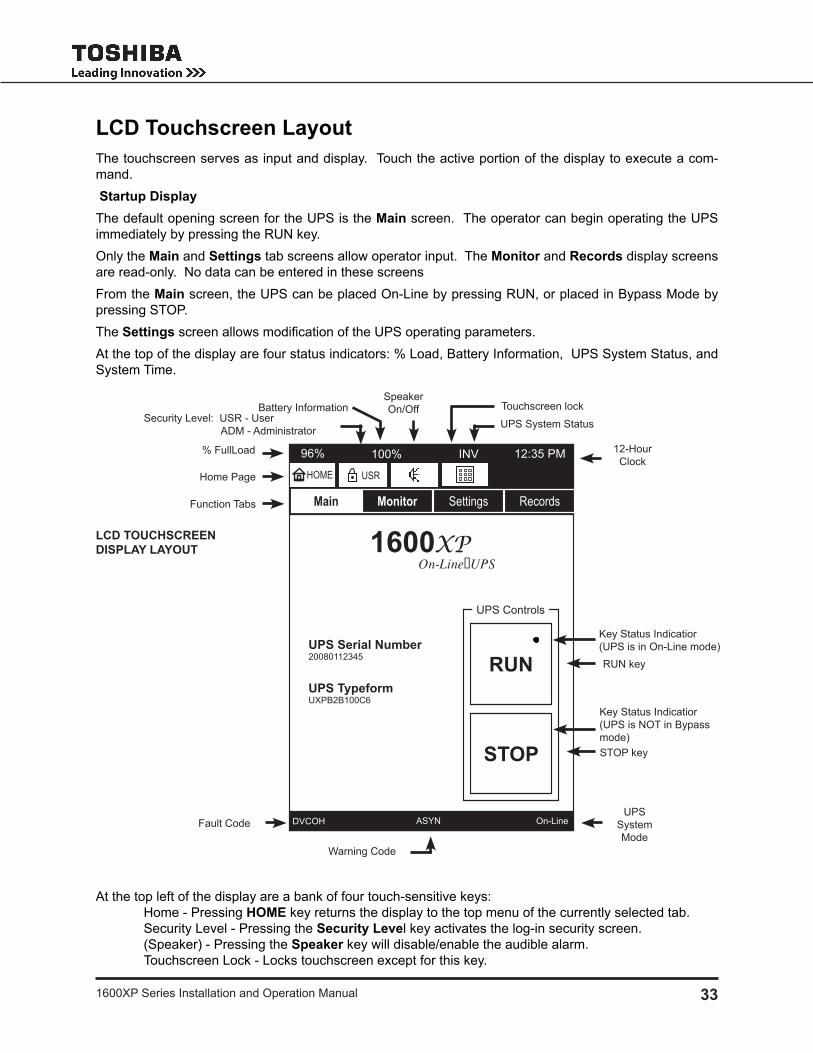
331600Xp Series installation and operation manual
LCD Touchscreen Layoutthe touchscreen serves as input and display. touch the active portion of the display to execute a com-mand. Startup Displaythe default opening screen for the UpS is the Main screen. the operator can begin operating the UpS immediately by pressing the rUn key.only the Main and Settings tab screens allow operator input. the Monitor and Records display screens are read-only. no data can be entered in these screensFrom the Main screen, the UpS can be placed on-line by pressing rUn, or placed in bypass mode by pressing Stop.the Settings screen allows modification of the UPS operating parameters. At the top of the display are four status indicators: % load, battery information, UpS System Status, and System time.
At the top left of the display are a bank of four touch-sensitive keys: Home - pressing HOME key returns the display to the top menu of the currently selected tab. Security level - pressing the Security Level key activates the log-in security screen. (Speaker) - pressing the Speaker key will disable/enable the audible alarm. touchscreen lock - locks touchscreen except for this key.
LCD TOUCHSCREEN DISPLAY LAYOUT
UpS System Status
warning Code
UpS System mode
Fault Code
12-Hour Clock
Security level: USr - User Adm - Administrator
Function tabs
Home page
rUn key
Stop key
on-linedVCoH ASyn
1600XPOn-Line UPS
UPS Serial Number20080112345
UPS TypeformUXpb2b100C6
RUN
STOP
UpS Controls
Speaker on/off
Main Monitor Settings Records
12:35 pminV
HOME USR
touchscreen lock
96% 100%% Fullload
battery information
key Status indicatior(UpS is in on-line mode)
key Status indicatior(UpS is not in bypass mode)

34 1600Xp Series installation and operation manual
the second row of keys are the function tabs.At the bottom of the display three event codes display the latest operational information: Faults, warnings, and the current UpS System mode. (See pages 53–56.)
Operating Keys the icons listed in the table below identify the touch-sensitive keys on the main touchscreen. the keys are different types of controls that can be activated by pressing that area of the touchscreen.
Key Functional Descriptionrun key - press and hold the key 1-2 seconds (until the UpS ‘beeps’) to put the UpS in on-line mode. the active status indicator (upper left hand dot) will appear on the rUn key and disappear from the Stop key..Stop key - press and hold the key 1-2 seconds (until the UpS ‘beeps’) to put the UpS in bypass mode. the active status indicator (upper left hand dot) will appear on the Stop key and disappear from the rUn key.
Home key - press to return to top menu of respective tab.
Security level key. press to open security login screen.
event Alarm mute key- press to silence current event alarm.
Alarm muted key- Alarm remains silenced until next event.
touchscreen enabled key- press to disable (lockout) all touchscreen keys except this key.touchscreen disabled key - press to enable (un-lock) touchscreen.
Four function tab keys: main, monitor, Settings, records main - Start and Stop keys, UpS Serial number and typeform. monitor - Shows mimic display for accessing input/output/bypass/battery data. Settings - provides access to adjustable performance parameters. records - Access fault, warning and other records.
As displayed on: Monitor and Settings screens:
Records screens:
go to First page/record key.
go to previous page/record key.
menu selection under monitor and Settings tabs.
Shows the current page or record number, and total number of pages or records.
go to next page/record key.
go to last page/record key.
2 / 3
2 / 3
bAt
bAt 2 / 3
USR
HOME
Main
Monitor
Settings
Records
RUN RUN
STOP STOP

351600Xp Series installation and operation manual
Status Indicatorsthe four top and three bottom UpS status indicators on the main screen and their meanings are listed in the table below. .
Indicator Functional Description96% Shows the current load percentage.
100% / 11’100% / 9’ 35”
100% / n/A
battery information: in on-line and battery back-up mode the display alternates between battery charge percentage and estimated remaining battery runtime in: minutes for runtimes > 10 min. minutes and Seconds for runtimes < 10 min.
in other modes, the display alternates between battery charge percentage and “n/A.”
inV Shows current UpS Status. indicator will change as the UpS status changes. For a detailed listing see page 56.
12:35 pm System time
dVCoH Fault description Code - For a detailed listing see 53.
ASyn warning description Code - For a detailed listing see page 54.
on-line Current operating mode of the UpS - For a detailed listing see page 56.
Light Emitting Diodes (LED)the following table describes the front panel led behaviors and the associated meaning.
LED Behavior Significance/Meaninggreen - on UpS is in on-line, backup, or battery test mode.green - oFF UpS in bypass mode.green - oFF UpS in shutdown mode.red - on one or more faults occurred. See Records: Faults for details. red - Flashing Charger overvoltage occurred.red - oFF no fault occurred.
Amber - on Service Call needed, Less than 6 mo. of Battery Life or Battery Life End.
Amber - Flashing one or more warnings occurred. See Records: Warnings for details. Amber - oFF no warning (normal, UpS in operation).
green - on Input and Bypass voltage is within specified range.green - Flashing Input and Bypass voltage is over specified range.green - oFF Input and Bypass voltage is under specified range.
NOTE: On-Line/Fault LEDs - Appear Orange if Green and Red flash concurrently.
AC input
warning
on-line/ Fault

36 1600Xp Series installation and operation manual
Touchscreen Menu Tree
Front Panel Layoutthe diagram below shows the menu tree for the touchscreen display. the four folder tabs and their associated sub-menu choices are shown on the left, and a description of the displays /choices are detailed on the right.
MAIN – displays the starting screen. it has a RUN and STOP key that place the UpS in in-line or bypass mode respectively.
MONITOR – graphically displays the current status of the UpS (on-line, backup, bypass, Shutdown) in an interactive power flow block diagram. Selecting one of the blocks provides additional detailed data of the input (IN), output (OUT), bypass (BYP), battery (BAT), and dC bus (DC), Control & Configura-tion (C&C), and display & external (D&E) devices.
SETTINGS – Allows monitoring and/or modification of UPS pa-rameters. parameters that can be viewed or modified vary depending on the security level of the login password entered using keypad.
Records – displays the most re-cent 32 Test, Backup, Faults, Warning, Operation, and System change records.
System records are only available at the distributor and depot security levels.
in any record set, if more than 32 incidences have occurred, only the most recent 32 record are retained in each report.
Tab: Main ID/RUN-STOP
Tab: Settings Settings Menu
Disp/Reye
Ctrl/Cfg
DC Bus
Output
ID Input
History
Batt
Bypass
Tab: Records Records Menu
Warnings
Backup
SystemOperation
Faults
Test
Tab: Monitor Monitor Menu
BYP
OUT
DC
IN BAT
D&E
C&C

371600Xp Series installation and operation manual
Screen Tab: Main
the main tab is also the opening tab on startup for the UpS. press RUN to place the UpS in on-line mode, and press STOP to place the UpS in bypass mode.
RUN/Stop the UPSpress and momentarily hold (approximately one to two seconds) the RUN or STOP key to place the UpS in on-line or bypass mode respectively.
the touchscreen display can be disabled for safety or convenience by pressing the touchscreen lockout key,
.
(note: the touchscreen lockout key is disabled when the screen is in keypad mode.)
the lockout key will change to and the touch-screen will not respond to any input except a touch to the lockout key.
touching the lockout key again will toggle the lockout off, the graphic will change to indicating the touch-screen is active.
MAIN SCREEN
on-linedVCoH ASyn
1600XPOn-Line UPS
UPS Serial Number20080112345
UPS TypeformUXpb2b100C6
RUN
STOP
UpS Controls
Main Monitor Settings Records
12:35 pminV
HOME USR
MAIN SCREEN DISABLED
on-linedVCoH ASyn
1600XPOn-Line UPS
UPS Serial Number20080112345
UPS TypeformUXpb2b100C6
RUN
STOP
UpS Controls
Main Monitor Settings Records
12:35 pminV
HOME USR
96% 100%
96% 100%

38 1600Xp Series installation and operation manual
Keypad Controlsthe keypad uses a alphanumeric format similar to that used on telephone 12-key keypad. rapidly press a key 1 to 5 times to select the desired character. For instance, quickly press the 7PQRS key four times to enter an “r.”
pause a moment, then key in the next value.
press the backspace key to delete the last character entered.
the keypad can be toggled to access to lower case let-ters and the space “ “ key by pressing the Shift key. enter the lower case letters as above.
the Space key is used to enter a space between alpha-numeric characters.
example: by using the additional characters available with the shift key you can type in a device name:
“toshiba H3” instead of “toSHibAH3”
return to the Upper Case format keypad by pressing Shift again.
exit the keypad display by pressing either the Quit or Write key.
on-linedVCoH ASyn
Main Monitor Settings Records
12:35 pminV
HOME USR
USR
2ABC
5JKL
8TUV
0-:
1./
4GHI
7PQRS
3DEF
6MNO
9WXYZ
Shift
Quit
Write
619 Change Secu. Lvl
KEYPAD
on-linedVCoH ASyn
Main Monitor Settings Records
12:35 pminV
HOME USR
USR
2abc
5jkl
8tuvV
1./
4ghi
7pqrs
3def
6mno
9wxyz
Shift
Quit
Write
619 Change Secu. Lvl
SHIFTED KEYPAD
“Space” key
backspace key
96% 100%
96% 100%

391600Xp Series installation and operation manual
Screen: Security Passwords & Keypadthe UpS has several levels of security password avail-able: USer (USr) , Admin (Adm), and other security levels for use by service and factory representatives. the security level is indicated on the Security key.the UpS stays in a security level until a new level is entered. For example, once the UpS is placed in the USr level, it remains at that level until the security level is changed.
Login:press the 1. Security Level key, USR . the keypad replaces the main screen to allow en-2. tering the password. by default the password are set to:
User: USer Administrator: Admin
typing in USer in the keypad will change the se-3. curity level to User. enter the password using the alphanumeric keys.press 4. Write to store the password in the UpS. if the password is accepted the text “Successful” will display at the bottom left of the touchpad, as shown here.
if the password entered was not accepted, the text “error15 – write Function” or some similar message will indicate that the password or level change was not ac-cepted.
press the 5. QUIT key and the keypad will close and the original display restored.
this same keypad is used for data input for parameters in the Settings tab.
KEYPAD
on-linedVCoH ASyn
Main Monitor Settings Records
12:35 pminV
HOME USR
USER
2ABC
5JKL
8TUV
0-:
1./
4GHI
7PQRS
3DEF
6MNO
9WXYZ
Shift
Quit
Write
619 Change Secu. Lvl
Successful
96% 100%

40 1600Xp Series installation and operation manual
Screen Tab: Monitor
The top screen under the Monitor tab is a graphical power flow block diagram that acts as a mimic display showing power flow through the UPS sections (Input, Output, Bypass, and Battery) and the UPS status (on-line, backup, bypass, Shutdown). Additional information screens are available that display the de-tailed status of the various parameters for the input, output, bypass, battery, dC bus, System Status, and remote Communications.
the monitor tab illustration, next page, shows the screens available and how to navigate between them.
Mimic Displayin the mimic display of the monitor tab screen, the four UpS selection keys, input (IN), dC bus, (DC) output (OUT), bypass (BYP), and battery (0) are connected by lines indicating power flow. A thick line indicates power flowing, and thin line indicates no power flowing.
The Monitor display, below, shows the UPS in Shutdown Mode: Power is flowing to charge the battery, but no power is going to the bypass or output.
Monitor Detailspress the IN, BYP, OUT, DC, or BAT key on the mimic display to view the parameter details for that section of the UpS.
The MONITOR TAB figure on the following page shows the relationship of the various data displays.
press the Home key, Home , to return to the opening monitor tab screen.
MIMIC DISPLAY STATUS INDICATOR
on-linedVCoH ASyn
Main Monitor Settings Records
12:35 pminV
HOME USR
BYP
BAT
D&E
IN OUTDC
C&C
MIMIC DISPLAY
ON-LINE MODE BYPASS MODE
BACKUP MODE OUTPUT SHUTDOWN MODE
on-line
Main Monitor Settings Records
12:35 pminV
HOME USR
BYP
BAT
D&E
IN OUTDC
C&C
bypassdVCoH ASyn
Main Monitor Settings Records
12:35 pmbyp
HOME USR
BYP
BAT
D&E
IN OUTDC
C&C
backupdVCoH ASyn
Main Monitor Settings Records
12:35 pminV
HOME USR
BYP
BAT
D&E
IN OUTDC
C&C
ShutdowndVCoH ASyn
Main Monitor Settings Records
12:35 pmwrn
HOME USR
BYP
BAT
D&E
IN OUTDC
C&C
96% 100%96% 100% 96% 100%
96% 100% 96% 100%
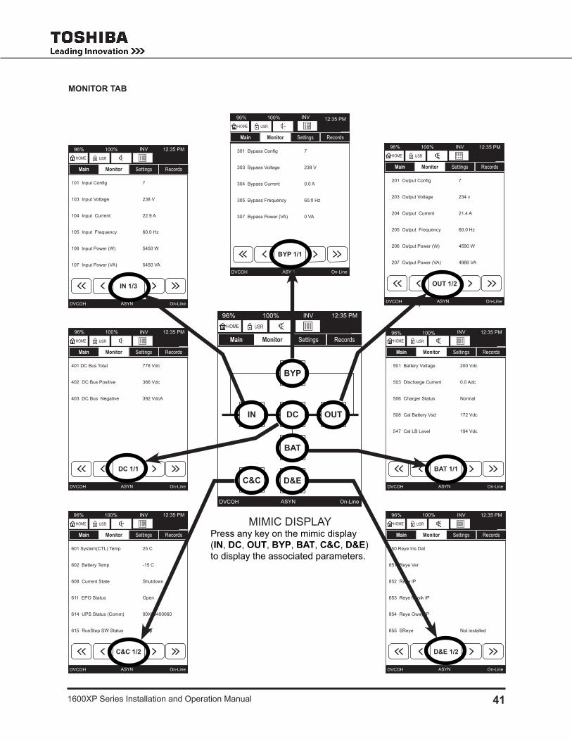
411600Xp Series installation and operation manual
MONITOR TAB
on-linedVCoH ASyn
Main Monitor Settings Records
12:35 pminV
HOME USR
BYP
BAT
D&E
IN OUTDC
C&C
on-linedVCoH ASyn
Main Monitor Settings Records
12:35 pminV
HOME USR
IN 1/3
101 Input Config
103 input Voltage
104 input Current
105 input Frequency
106 input power (w)
107 input power (VA)
7
238 V
22.9 A
60.0 Hz
5450 w
5450 VA
on-linedVCoH ASyn
Main Monitor Settings Records
12:35 pminV
HOME USR
DC 1/1
401 dC bus total
402 dC bus positive
403 dC bus negative
778 Vdc
366 Vdc
392 VdcA
on-linedVCoH ASyn
Main Monitor Settings Records
12:35 pminV
HOME USR
BYP 1/1
301 Bypass Config
303 bypass Voltage
304 bypass Current
305 bypass Frequency
307 bypass power (VA)
7
238 V
0.0 A
60.0 Hz
0 VA
on-linedVCoH ASyn
Main Monitor Settings Records
12:35 pminV
HOME USR
BAT 1/1
501 battery Voltage
503 discharge Current
506 Charger Status
508 Cal battery Vsd
547 Cal lb level
200 Vdc
0.0 Adc
normal
172 Vdc
194 Vdc
on-linedVCoH ASyn
Main Monitor Settings Records
12:35 pminV
HOME USR
OUT 1/2
201 Output Config
203 output Voltage
204 output Current
205 output Frequency
206 output power (w)
207 output power (VA)
7
234 v
21.4 A
60.0 Hz
4590 w
4986 VA
on-linedVCoH ASyn
Main Monitor Settings Records
12:35 pminV
HOME USR
C&C 1/2
601 System(Ctl) temp
602 battery temp
608 Current State
611 epo Status
614 UpS Status (Comm)
615 runStop Sw Status
25 C
-15 C
Shutdown
open
00X00400060
Stop
on-linedVCoH ASyn
Main Monitor Settings Records
12:35 pminV
HOME USR
D&E 1/2
850 reye ins dat
851 reye Ver
852 reye ip
853 reye masik ip
854 reye gway ip
855 Sreye not installed
mimiC diSplAypress any key on the mimic display (IN, DC, OUT, BYP, BAT, C&C, D&E) to display the associated parameters.
96% 100%
96% 100%
96% 100%
96% 100%
96% 100%
96% 100%
96% 100%96% 100%

42 1600Xp Series installation and operation manual
Screen Tab: Settingsthe tables on pages 47 – 51 list the 1600Xp Settings parameters that can be viewed in the monitor tab. example: the Settings parameter Batt Test Freq (battery test Frequency) can be viewed by USr (User) level and above, only logged in Adm (Administrators) and above can edit the value.each key displays a block of relevant command parameters: Key – (Cmd ID range) Types of Parameters
ID –• (000-099) UPS specific information such as serial number, software versions, installation date.Input –• (100-199) input measured/calculated data such as input voltage, frequency, current, power, over-/under- voltage settings.Output –• (200-299) output measured/calculated data such as output voltage, frequency, current, power, over-/under- voltage settings.Bypass –• (300-399) Bypass data such as configuration, voltage, current, power, OV detection level.DC Bus –• (400-499) data such as total voltage, rated voltage, positive and negative bus voltages.Batt –• (500-599) battery voltage, charger status, total discharges, shutdown voltage.Ctrl/Cfg –• (600-699) Control and configuration list system and battery temperatures, system status, startup delay, auto-transfer window, restart mode.History –• (700-799) History lists metrics like system operation time, total over loads, hi system temp.Disp/Reye –• (800-849) Display specific parameters like Disp. Firmware version, sleep timer, buzzer status, display calibration points, and remoteye iii settings.
(850-859) lists remoteye iii ip address, ip mask, Status, baud rate, datalink status.
on-line
Main Monitor Settings Records
12:35 pminV
HOME USR
Ctrl/Cfg History
ID Input
Output Bypass
DC Bus Batt
Disp/Reye Debug
SETTINGS OPENING SCREEN
96% 100%

431600Xp Series installation and operation manual
ID BLOCK
BYPASS BLOCK
CTRL/CFG (SCC)BLOCK
on-linedVCoH ASyn
Main Monitor Settings Records
12:35 pminit
HOME USR
ID 1/3
001 manufacturer
002 typeform
003 Serial no.
004 main Fware Ver
005 main bSector Ver
006 main bloader Ver
toSHibA
UH3g2l060C6
20080112345
UH3mSV00013
UH3mbS01000
UH3mbl01000
on-linedVCoH ASyn
Main Monitor Settings Records
12:35 pminit
HOME USR
BYP 1/1
302 no of bypass line
315 VbypUV delevel*
316 VbypUV relevel*
317 VbypoV delevel*
318 VbypoV relevel*
1 line
62 %
66 %
284 V
274 V
on-linedVCoH ASyn
Main Monitor Settings Records
12:35 pmFlt
HOME USR
C&C 1/5
609 requested State
610 timed operation
612 Faults
613 warnings
619 Change Secu. lvl
621 reset Admin pwe
idle
0 Sec
0x00020000
0x00000060
USr
idle
INPUT BLOCK
DC BUS BLOCK
HIST BLOCK
on-linedVCoH ASyn
Main Monitor Settings Records
12:35 pmepoHOME USR
IN 1/1
102 no of input line
111 rated Vin*
119 VioV delevel*
120 VioV relevel*
141 Freq on Fierr*
1 line
240 V
274 V
264 V
50.0 Hz
on-linedVCoH ASyn
Main Monitor Settings Records
12:35 pmFlt
HOME USR
DC 1/1
404 rated dC bus* 770 Vdc
on-linedVCoH ASyn
Main Monitor Settings Records
12:35 pmFlt
HOME USR
HIS 1/4
701 System op time
702 inverter op time
703 backup op time
704 UpS lifetime
705 Hi System temp
706 Hi battery temp
07031 Sec
0 Sec
0 Sec
6118 Hr0
28 C
-8 C
OUTPUT BLOCK
BATT BLOCK
DISP/REYE BLOCK
on-linedVCoH ASyn
Main Monitor Settings Records
12:35 pmFlt
HOME USR
BAT 1/3
507 total discharges
509 batt life remain
511 rated Ahr*
512 no batt (Series)*
513 no batt (paral)*
514 batt install date
0
4341 Hr
9 AHr
18
1
8/24/2009
on-linedVCoH ASyn
Main Monitor Settings Records
12:35 pmFlt
HOME USR
D&E 1/4
801 dFw Ver
802 dFw bdate
803 dFw btime
804 dbS Ver
805 dbl Ver
807 tmrsleep
UX3FV00000
Feb 25 2009
15:29:50
UH3dbS01000
UH3dbl01000
10 min
on-linedVCoH ASyn
Main Monitor Settings Records
12:35 pmFltHOME USR
OUT 1/1
202 no of output line
215 rated Volt*
220 VoUV delevel*
222 VooV delevel*
224 Fo Syn window*
226 Vout Adjust
1 line
240 V
90 %
110 %
1.0 Hz
5 /128
96% 100% 96% 100%
96% 100% 96% 100%96% 100%
96% 100%96% 100% 96% 100%
96% 100%

44 1600Xp Series installation and operation manual
Changing UPS Parameter Settings
press the parameter to be changed and the display will open with an appropriate data entry screen. Settings that cannot be changed will respond with “item cannot be changed” shown at the bottom of this page.
Some parameters will display one of a set of fixed values, such as example 1.
example 1:
the UpS can have either one or two input lines. the value displayed in the Active Value box is the parameter in use. Alternate values are displayed in keys below the Active Value box.
After selecting the parameter value, press Write to write the entered value to the UpS memory and return to the original parameter screen.
Some parameters can be any of a range of values, such as rated Volt-age in example 2.
example 2:
the rated Voltage in can vary over a range. press the “rated Vin” pa-rameter listing and enter the correct value in the Active Value box. using the standard alphanumeric keypad.
Use the back arrow to delete an incorrect keystroke.
After changing the parameter value, press Write to write the entered value to the UpS memory.
Some parameters are informational, some can be changed by the user, and others can only be changed by a higher security access. if a param-eter cannot be changed under the current security access level, selecting the parameter for change will generate the message “Item cannot be changed”.
press OK to return to the original display.
on-line
Main Monitor Settings Records
12:35 pminV
HOME USR
Quit
Write
102 No of Input Line
240V
230V
5JKL
8TUV
0-:
208V
4GHI
7PQRS
240V
6MNO
9WXYZ
Shift
on-line
Main Monitor Settings Records
12:35 pminV
HOME USR
Quit
Write
117 VIUV Hysteresis*
8
2 ABC
5JKL
8TUV
0-:
1./
4GHI
7PQRS
3DEF
6MNO
9WXYZ
Shift
on-linedVCoH ASyn
Main Monitor Settings Records
12:35 pminit
HOME USR
1 / 32
Item cannot be changed
OK
96% 100%
96% 100%
96% 100%

451600Xp Series installation and operation manual
Recalibrate the Touchscreen
the touchscreen on the UpS is shipped from the factory already calibrated. However, at some point the touchscreen calibration may need to be refreshed so that the active portion of the screen matches the underlying graphics.
recalibrate the touchscreen as follows:
press the 1. Settings tab.
press the 2. Disp/Reye key.
page forward to the second page and press the line: 3. 810 Cali Display
the settings display will show the Cali display screen.4.
press the 5. Enable key.
press the 6. Write key. (this will write the subsequent calibration val-ues to the Control board.)
the display will switch to the C7. AlibrAtion SCreen shown below.
Gently press a stylus, or similar fine pointed tool, to the center of the 8. X located at the top left-hand side of the display.
As soon as the information is read, a second X will be displayed at 9. the top right-hand of the display. repeat Step 7.
repeat Step 7 for X displayed at the lower right-hand side of the 10. display.
repeat Step 7 for the X displayed at the lower left-hand side of the 11. display.
After completing Step 10, the display will return to the 12. Cali Display screen. press the Quit key.
the touchscreen has been successfully recalibrated and the resulting values stored on the Control pCb.
on-line
Main Monitor Settings Records
12:35 pminV
HOME USR
Quit
Write
810 Cali Display
Disabled
Enable
5JKL
8TUV
0-:
208V
4GHI
7PQRS
240V
6MNO
9WXYZ
Shift
Cali display SCreen
CAlibrAtion SCreen

46 1600Xp Series installation and operation manual
Settings Parametersthe following table lists parameters parameters that can be viewed under the monitor tab of the touch-screen display.
the security levels are, from lowest to highest level: Access Level Sec. Abbreviation User USr Administrator Adm the table headings are:
Cmd ID• - Command id number. A three digit number between 000 and 999. not all numbers have an associated parameter.Description on LCD• - display text, often abbreviated.Brief Description• - brief description of the function of the parameter.Location Map - Tab/Blk• - gives the menu location for the parameter by tab and block. the tabs are main, monitor, Settings, records.
e.g. Cmd 501 (battery Voltage can be viewed under the monitor tab, in the bAtt block) UPS Status is displayed in the display header Status field. UpS Faults and warnings are shown in the display footer, at the bottom of the display.Example• - Shows an example of the parameter displayed on the touchscreen.Rqd Security Level to Change/By• - the required security level to change a parameters value or set-ting: User, Administrator, distributor.

471600Xp Series installation and operation manual
1600
xP C
omm
and
Para
met
ers
Tabl
eC
md
IDD
escr
iptio
n on
LC
DB
rief D
escr
iptio
nLo
catio
n M
apEx
ampl
eR
qd S
ecur
ity
Leve
l to
chan
geB
yTa
bB
lock
001
man
ufac
ture
r
Up
S m
anuf
actu
rer
- Sto
res
up to
16
char
acte
rs.
Set
tings
id
to
SH
ibA
non
chan
geab
le
non
chan
geab
leU
ser
Adm
inis
trato
r00
2ty
pefo
rm*
Up
S t
ypef
orm
Set
tings
id
U
H3b
2b06
0C6
n
onch
ange
able
n
onch
ange
able
Use
r A
dmin
istra
tor
003
Ser
ial n
o.U
pS
Ser
ial n
umbe
r1.
mai
n
2. S
et-
tings
id
2008
0112
345
non
chan
geab
le
non
chan
geab
leU
ser
Adm
inis
trato
r
004
mai
n Fw
are
Ver
m
ain
Firm
war
e Ve
rsio
n - t
he la
st 5
dig
it re
pres
ents
mai
n C
ontro
ller’s
so
ftwar
e ve
rsio
n. in
this
exa
mpl
e, th
e ve
rsio
n is
1.0
00
Set
tings
id
U
H3m
Sw
0100
0
non
chan
geab
le
non
chan
geab
leU
ser
Adm
inis
trato
r
005
mai
n b
Sec
tor
Ver
mai
n b
oots
ecto
r Ver
sion
- t
he la
st 5
dig
it re
pres
ents
mai
n C
ontro
ller’s
b
oots
ectio
r Ver
sion
. in
this
exa
mpl
e, th
e ve
r-si
on is
1.0
00
Set
tings
id
U
H3m
bS
0100
0 n
onch
ange
able
n
onch
ange
able
Use
r A
dmin
istra
tor
006
mai
n b
load
er
Ver
mai
n b
ootlo
ader
Ver
sion
- t
he la
st 5
dig
it re
pres
ents
mai
n C
ontro
ller’s
b
ootlo
ader
sof
twar
e ve
rsio
n. in
this
exa
mpl
e,
the
vers
ion
is 1
.000
Set
tings
id
U
H3m
bl0
1000
n
onch
ange
able
n
onch
ange
able
Use
r A
dmin
istra
tor
007
Job
no.
Job
num
ber
- tos
hiba
’s m
anuf
actu
ring
job
num
ber.
Set
tings
id
Jb
0123
4567
89
non
chan
geab
le
non
chan
geab
leU
ser
Adm
inis
trato
r00
8te
st p
erso
n
te
st p
erso
n’s
Firs
t and
las
t ini
tial
Set
tings
id
t
An
onch
ange
able
n
onch
ange
able
Use
r A
dmin
istra
tor
009
test
dat
e
Up
S t
est d
ate
at th
e p
rodu
ctio
n - F
orm
at is
yy
yy
mm
dd
Set
tings
id
20
0801
01
non
chan
geab
le
non
chan
geab
leU
ser
Adm
inis
trato
r01
0H
war
e b
uilt
dat
e H
ardw
are
bui
lt d
ate
- For
mat
is y
yy
ym
md
dS
ettin
gs
id
2008
0101
n
onch
ange
able
n
onch
ange
able
Use
r A
dmin
istra
tor
013
mai
n e
ep
ro
m
Ver
mai
n e
ep
ro
m V
ersi
onS
ettin
gsid
non
chan
geab
le
non
chan
geab
leU
ser
Adm
inis
trato
r01
5S
yste
m n
ame
S
yste
m n
ame
Set
tings
id
to
SH
ibA
H3,
C
ontro
l pla
ntn
onch
ange
able
C
hang
eabl
eU
ser
Adm
inis
trato
r01
6A
ttach
ed d
e-vi
ce
Up
S A
ttach
ed d
evic
esS
ettin
gs
id
no
ne
n
onch
ange
able
C
hang
eabl
eU
ser
Adm
inis
trato
r 01
7in
stal
led
dat
e
Up
S in
stal
led
dat
e at
end
use
r site
Set
tings
id
20
0801
01n
onch
ange
able
C
hang
eabl
eU
ser
Adm
inis
trato
r

48 1600Xp Series installation and operation manual
1600
xP C
omm
and
Para
met
ers
Tabl
eC
md
IDD
escr
iptio
n on
LC
DB
rief D
escr
iptio
nLo
catio
n M
apEx
ampl
eR
qd S
ecur
ity
Leve
l to
chan
geB
yTa
bB
lock
101
Inpu
t Con
fig
In
put C
onfig
urat
ion
whi
ch te
ll th
e vo
ltage
and
fre
quen
cy.
mon
itor
in
240V
- 60
Hz
non
chan
geab
le
non
chan
geab
leU
ser
Adm
inis
trato
r10
2n
o of
inpu
t li
ne
no
of in
put l
ines
- A
lway
s 1
inpu
t lin
e fo
r 160
0Xp
serie
sS
ettin
g in
1
line
non
chan
geab
le
non
chan
geab
leU
ser
Adm
inis
trato
r10
3in
put V
olta
ge
in
put V
olta
ge
- Up
S p
rese
ntly
cal
cula
ted
inpu
t vol
tage
mon
itor
in
240
Vn
onch
ange
able
n
onch
ange
able
Use
r A
dmin
istra
tor
104
inpu
t Cur
rent
inpu
t Cur
rent
- U
pS
pre
sent
ly c
alcu
late
d in
put c
urre
ntm
onito
r in
25
.0 A
non
chan
geab
le
non
chan
geab
leU
ser
Adm
inis
trato
r10
5in
put F
re-
quen
cy
inpu
t Fre
quen
cy
- Up
S p
rese
ntly
cal
cula
ted
inpu
t fre
quen
cym
onito
r in
60
.0 H
zn
onch
ange
able
n
onch
ange
able
Use
r A
dmin
istra
tor
106
inpu
t pow
er(w
)in
put A
ctiv
e p
ower
- U
pS
pre
sent
ly c
alcu
late
d in
put a
ctiv
e po
wer
. if
Up
S c
an n
ot c
alcu
late
for i
nput
app
aren
t p
ower
, dis
play
sho
ws
n/A
.
mon
itor
in
5100
w
non
chan
geab
le
non
chan
geab
leU
ser
Adm
inis
trato
r
107
inpu
t p
ower
(VA
) in
put A
ppar
ent p
ower
- U
pS
pre
sent
ly c
alcu
late
d in
put a
ppar
ent
pow
er (i
nput
vol
tage
* in
put c
urre
nt)
mon
itor
in
6000
VA
non
chan
geab
le
non
chan
geab
leU
ser
Adm
inis
trato
r
108
inpu
t pFa
ctor
in
put p
ower
Fac
tor
- if c
onve
rter i
s no
t run
ning
, dis
play
sho
ws
n/A
.m
onito
r in
1.
0n
onch
ange
able
n
onch
ange
able
Use
r A
dmin
istra
tor
111
rat
ed V
in*
rat
ed in
put V
olta
ge
- Use
d to
cal
cula
te p
erce
ntag
e an
d re
quire
d to
se
tup
prop
erly
at v
ery
first
tim
e st
artu
p.
Set
ting
in
240
V
non
chan
geab
le
Cha
ngea
ble
Use
r A
dmin
istra
tor
112
rat
ed ii
n
rat
ed in
put C
urre
nt
- Use
this
set
up to
cal
cula
ted
perc
enta
ge.
mon
itor
in
25.0
An
onch
ange
able
n
onch
ange
able
Use
r A
dmin
istra
tor
113
rat
ed F
in
rat
ed in
put F
requ
ency
- d
etec
ted
if au
to d
etec
tion
and
man
ual
mon
itor
in
60.0
Hz
non
chan
geab
le
non
chan
geab
leU
ser
Adm
inis
trato
r11
9V
ioV
del
evel
in
put o
verv
olta
ge d
etec
tion
leve
l - O
f rat
ed in
put v
olta
ge w
hich
was
con
figur
ed
with
Com
man
d id
111
.
Set
ting
in
274
V
non
chan
geab
le
non
chan
geab
leU
ser
Adm
inis
trato
r
120
Vio
V r
elev
el
inpu
t ove
rvol
tage
rec
over
y le
vel -
of r
ated
in
put v
olta
ge w
hich
was
con
figur
ed w
ith C
om-
man
d id
111
.
Set
ting
in
264
V
non
chan
geab
le
non
chan
geab
leU
ser
Adm
inis
trato
r
135
inpu
t Vol
t-ag
e(%
) in
put V
olta
ge p
erce
ntag
e m
onito
r in
10
0 %
non
chan
geab
le
non
chan
geab
leU
ser
Adm
inis
trato
r

491600Xp Series installation and operation manual
1600
xP C
omm
and
Para
met
ers
Tabl
eC
md
IDD
escr
iptio
n on
LC
DB
rief D
escr
iptio
nLo
catio
n M
apEx
ampl
eR
qd S
ecur
ity
Leve
l to
chan
geB
yTa
bB
lock
136
inpu
t Cur
-re
nt(%
) in
put C
urre
nt p
erce
ntag
em
onito
r in
10
0 %
non
chan
geab
le
non
chan
geab
leU
ser
Adm
inis
trato
r13
7V
iUV
del
evel
in
put U
nder
volta
ge d
etec
tion
- C
alcu
late
d ac
cord
ing
to lo
ad a
nd a
djus
ted
by
itsel
f.
mon
itor
in
190
V
non
chan
geab
le
non
chan
geab
leU
ser
Adm
inis
trato
r
138
ViU
V r
elev
el
inpu
t Und
ervo
ltage
rec
over
y
- Cal
cula
ted
acco
rdin
g to
load
and
adj
uste
d by
its
elf.
mon
itor
in
200
Vn
onch
ange
able
n
onch
ange
able
Use
r A
dmin
istra
tor
139
rat
ed
inp
ower
(w)
rat
ed in
put p
ower
in w
att
- Cal
cula
ted
from
type
form
com
man
d id
002
.m
onito
r in
60
00 w
non
chan
geab
le
non
chan
geab
leU
ser
Adm
inis
trato
r14
1Fr
eq o
n Fi
-e
rr
*
Freq
set
up o
n in
put f
requ
ency
err
or
- tos
hiba
Up
S tr
y to
det
ect i
nput
freq
uenc
y bu
t ve
ry ti
ny p
erce
ntag
e w
hen
Up
S c
an n
ot d
etec
t th
e in
put f
requ
ency
bec
ause
of fl
uctu
atio
n,
1600
Xp
Up
S w
ill s
tart
by u
sing
this
set
up.
Set
ting
in
60.0
Hz
non
chan
geab
le
Cha
ngea
ble
Use
r A
dmin
istra
tor
201
Out
put C
onfig
O
utpu
t Con
figur
atio
n
- dis
play
s th
e vo
ltage
and
freq
uenc
y 24
0 V
60
Hz,
or 2
08 V
60
Hz
mon
itor
oU
t 24
0V -
60H
zn
onch
ange
able
n
onch
ange
able
Use
r A
dmin
istra
tor
202
no
of o
utpu
t li
nen
o of
out
put l
ines
- A
lway
s 1
inpu
t lin
e fo
r 160
0Xp
serie
sS
ettin
g o
Ut
1 li
nen
onch
ange
able
n
onch
ange
able
Use
r A
dmin
istra
tor
203
out
put V
olta
ge
out
put V
olta
ge
- Up
S p
rese
ntly
cal
cula
ted
outp
ut v
olta
gem
onito
r o
Ut
240
Vn
onch
ange
able
n
onch
ange
able
Use
r A
dmin
istra
tor
204
out
put C
urre
nt
out
put C
urre
nt
- Up
S p
rese
ntly
cal
cula
ted
outp
ut c
urre
ntm
onito
r o
Ut
25.0
An
onch
ange
able
n
onch
ange
able
Use
r A
dmin
istra
tor
205
out
put F
re-
quen
cy
out
put F
requ
ency
- U
pS
pre
sent
ly c
alcu
late
d ou
tput
freq
uenc
ym
onito
r o
Ut
60.0
Hz
non
chan
geab
le
non
chan
geab
leU
ser
Adm
inis
trato
r20
6o
utpu
t p
ower
(w)
out
put A
ctiv
e p
ower
- U
pS
pre
sent
ly c
alcu
late
d ou
tput
act
ive
pow
er.
if U
pS
can
not
cal
cula
te fo
r out
put a
ctiv
e po
wer
, dis
play
sho
ws
n/A
. esp
ecia
lly, b
ypas
s an
d sh
utdo
wn
mon
itor
oU
t 51
00 w
non
chan
geab
le
non
chan
geab
leU
ser
Adm
inis
trato
r
207
out
put
pow
er(V
A)
out
put A
ppar
ent p
ower
- U
pS
pre
sent
ly c
alcu
late
d ou
tput
app
aren
t po
wer
.
mon
itor
oU
t 60
00 V
An
onch
ange
able
n
onch
ange
able
Use
r A
dmin
istra
tor

50 1600Xp Series installation and operation manual
1600
xP C
omm
and
Para
met
ers
Tabl
eC
md
IDD
escr
iptio
n on
LC
DB
rief D
escr
iptio
nLo
catio
n M
apEx
ampl
eR
qd S
ecur
ity
Leve
l to
chan
geB
yTa
bB
lock
209
out
put l
oad
(%)
out
put l
oad
per
cent
age
- Up
S p
rese
ntly
cal
cula
ted
outp
ut lo
ad p
erce
nt-
age
mon
itor
oU
t 10
0 %
non
chan
geab
le
non
chan
geab
leU
ser
Adm
inis
trato
r
215
rat
ed V
out*
rat
ed o
utpu
t Vol
tage
- m
ust b
e se
tup
prop
erly
at i
nitia
l sta
rtup.
r
ated
out
put v
olta
ge is
use
d to
cal
cula
te p
er-
cent
ages
for i
d 2
20, 2
22
Set
ting
oU
t 24
0 V
non
chan
geab
le
non
chan
geab
leU
ser
Adm
inis
trato
r
216
rat
ed io
ut
rat
ed o
utpu
t Cur
rent
- U
pS
cal
cula
ted
rate
d ou
tput
cur
rent
from
ty
pefo
rm c
omm
and
id 0
02.
mon
itor
oU
t 25
.0 A
non
chan
geab
le
non
chan
geab
leU
ser
Adm
inis
trato
r
217
rat
ed F
out
rat
ed o
utpu
t Fre
quen
cy
-UP
S c
onfig
ures
out
put f
requ
ency
acc
ordi
ng to
au
to o
r man
ual m
ode,
mon
itor
oU
t 60
.0 H
zn
onch
ange
able
n
onch
ange
able
Use
r A
dmin
istra
tor
218
rat
ed p
out(w
) r
ated
out
put A
ctiv
e p
ower
-
Cal
cula
ted
from
type
from
com
man
d id
002
.m
onito
r o
Ut
5100
wn
onch
ange
able
n
onch
ange
able
Use
r A
dmin
istra
tor
219
rat
ed p
out(V
A)
rat
ed o
utpu
t App
aren
t pow
er
- Cal
cula
ted
from
type
from
com
man
d id
002
.m
onito
r o
Ut
6000
VA
non
chan
geab
le
non
chan
geab
leU
ser
Adm
inis
trato
r22
0V
oU
V d
e-le
vel*
o
utpu
t Und
ervo
ltage
det
ectio
n le
vel i
n p
er-
cent
age
- Of r
ated
out
put v
olta
ge w
hich
was
con
figur
ed
with
Com
man
d id
215
.
Set
ting
oU
t 90
%n
onch
ange
able
n
onch
ange
able
Use
r A
dmin
istra
tor
222
Vo
oV
de-
leve
l*
out
put o
verv
olta
ge d
etec
tion
leve
l in
perc
ent-
age
- Of r
ated
out
put v
olta
ge w
hich
was
con
figur
ed
with
Com
man
d id
215
Set
ting
oU
t 11
0 %
non
chan
geab
le
non
chan
geab
leU
ser
Adm
inis
trato
r
224
Fo S
yn w
in-
dow
*
out
put F
requ
ency
Syn
chro
niza
tion
win
dow
Set
ting
oU
t 1.
0 H
zn
onch
ange
able
n
onch
ange
able
Use
r A
dmin
istra
tor
226
Vout
Adj
ust
out
put V
olta
ge A
djus
tmen
t - C
an a
djus
t up
to +
/- 5
incr
emen
t of o
ne in
or
der t
o in
crea
se o
r dec
reas
e ou
tput
vol
tage
to
com
pens
ate
line
volta
ge d
rop.
Set
ting
oU
t 0
non
chan
geab
le
Cha
ngea
ble
Use
r A
dmin
istra
tor
301
Byp
ass
Con
fig
Byp
ass
Con
figur
atio
n - w
hich
tell
the
volta
ge a
nd fr
eque
ncy
240
V 6
0 H
z or
208
V 6
0 H
z
mon
itor
by
p 24
0V -
60H
zn
onch
ange
able
n
onch
ange
able
Use
r A
dmin
istra
tor
302
no
of b
ypas
s li
nen
o of
byp
ass
line
s - A
lway
s 1
inpu
t lin
e fo
r 160
0Xp
serie
sS
ettin
g b
yp
1 li
nen
onch
ange
able
n
onch
ange
able
Use
r A
dmin
istra
tor

511600Xp Series installation and operation manual
1600
xP C
omm
and
Para
met
ers
Tabl
eC
md
IDD
escr
iptio
n on
LC
DB
rief D
escr
iptio
nLo
catio
n M
apEx
ampl
eR
qd S
ecur
ity
Leve
l to
chan
geB
yTa
bB
lock
303
byp
ass
Volta
ge
byp
ass
Volta
ge
- pre
sent
cal
cula
ted
bypa
ss v
olta
gem
onito
r b
yp
240
Vn
onch
ange
able
n
onch
ange
able
Use
r A
dmin
istra
tor
304
byp
ass
Cur
rent
b
ypas
s C
urre
nt
- Up
S p
rese
ntly
cal
cula
ted
bypa
ss c
urre
ntm
onito
r b
yp
25.0
An
onch
ange
able
n
onch
ange
able
Use
r A
dmin
istra
tor
305
byp
ass
Fre-
quen
cy
byp
ass
Freq
uenc
y - U
pS
pre
sent
ly c
alcu
late
d by
pass
freq
uenc
ym
onito
r b
yp
60.0
Hz
non
chan
geab
le
non
chan
geab
leU
ser
Adm
inis
trato
r30
7b
ypas
s p
ower
(VA
) b
ypas
s A
ppar
ent p
ower
- U
pS
pre
sent
ly c
alcu
late
d by
pass
app
aren
t po
wer
.
mon
itor
by
p 60
00 V
An
onch
ange
able
n
onch
ange
able
Use
r A
dmin
istra
tor
315
Vb
ypU
V d
e-le
vel*
b
ypas
s U
nder
volta
ge d
etec
tion
leve
l - p
er-
cent
age
of ra
ted
inpu
t vol
tage
com
man
d id
11
1.
Set
ting
by
p 62
%n
onch
ange
able
n
onch
ange
able
Use
r A
dmin
istra
tor
316
Vb
ypU
V
rel
evel
*
byp
ass
Und
ervo
ltage
rec
over
y le
vel i
n pe
r-ce
ntag
e - o
f rat
ed in
put v
olta
ge c
omm
and
id 1
11.
Set
ting
by
p 66
%n
onch
ange
able
n
onch
ange
able
Use
r A
dmin
istra
tor
317
Vb
ypo
V d
e-le
vel
b
ypas
s o
ver V
olta
ge d
etec
tion
leve
l in
Volt
Set
ting
by
p 28
4 V
non
chan
geab
le
non
chan
geab
leU
ser
Adm
inis
trato
r31
8V
byp
oV
r
elev
el
byp
ass
ove
r Vol
tage
rec
over
y le
vel i
n Vo
ltS
ettin
g b
yp
274
Vn
onch
ange
able
n
onch
ange
able
Use
r A
dmin
istra
tor
401
dC
bus
tot
al
d
C b
us V
olta
ge t
otal
- C
urre
ntly
cal
cula
ted
dC
bus
tota
l vol
tage
mon
itor
dC
77
0 V
dcn
onch
ange
able
n
onch
ange
able
Use
r A
dmin
istra
tor
402
dC
bus
pos
i-tiv
e
dC
bus
Vol
tage
(+)
- Up
S p
rese
ntly
cal
cula
ted
dC
bus
pos
itive
vo
ltage
mon
itor
dC
38
5 V
dcn
onch
ange
able
n
onch
ange
able
Use
r A
dmin
istra
tor
403
dC
bus
neg
a-tiv
e
dC
bus
Vol
tage
(-)
- Up
S p
rese
ntly
cal
cula
ted
dC
bus
neg
ativ
e vo
ltage
mon
itor
dC
38
5 V
dcn
onch
ange
able
n
onch
ange
able
Use
r A
dmin
istra
tor
404
rat
ed d
C b
us*
rat
ed d
C b
us V
olta
ge
- Use
d to
cal
cula
ted
perc
enta
ge.
Set
ting
dC
77
0 V
dcn
onch
ange
able
n
onch
ange
able
Use
r A
dmin
istra
tor
501
bat
tery
Vol
tage
C
harg
er o
r bat
tery
Vol
tage
- U
pS
cal
cula
tes
and
show
s cu
rren
t cha
rger
vo
ltage
dur
ing
char
ging
or b
atte
ry v
olta
ge d
ur-
ing
bac
kup
mon
itor
bAt
t 23
4 V
dcn
onch
ange
able
n
onch
ange
able
Use
r A
dmin
istra
tor

52 1600Xp Series installation and operation manual
1600
xP C
omm
and
Para
met
ers
Tabl
eC
md
IDD
escr
iptio
n on
LC
DB
rief D
escr
iptio
nLo
catio
n M
apEx
ampl
eR
qd S
ecur
ity
Leve
l to
chan
geB
yTa
bB
lock
503
dis
char
ge C
ur-
rent
bat
tery
dis
char
ge C
urre
nt
- Up
S c
alcu
late
s an
d sh
ows
disc
harg
ed c
urre
nt
durin
g b
acku
p an
d 0.
0 V
dc fo
r oth
ers
mod
es
of U
pS
mon
itor
bAt
t 22
.0 V
dcn
onch
ange
able
n
onch
ange
able
Use
r A
dmin
istra
tor
506
Cha
rger
Sta
tus
bat
tery
Cha
rger
Sta
tus
- Sho
ws
char
ger’s
sta
tus
whi
ch c
an b
e n
orm
al,
pre
vent
ive
and
Sto
p
mon
itor
bAt
t n
orm
aln
onch
ange
able
n
onch
ange
able
Use
r A
dmin
istra
tor
507
tota
l dis
char
g-es
n
umbe
r of b
atte
ry d
isch
arge
s - i
ncre
men
t cou
nt b
y on
e af
ter U
pS
in b
acku
p m
ode
for 1
0 se
cond
s
Set
tings
b
Att
123
non
chan
geab
le
non
chan
geab
le
508
Cal
bat
tery
Vsd
C
alcu
late
d b
atte
ry S
hutd
own
Volta
ge
- Cal
cula
ted
from
the
disc
harg
e ra
te d
urin
g b
acku
p m
ode
mon
itor
bAt
t 17
2 V
dcn
onch
ange
able
n
onch
ange
able
Use
r A
dmin
istra
tor
509
bat
t life
re-
mai
n b
atte
ry l
ifetim
e r
emai
ning
Set
tings
b
Att
4380
0 H
rn
onch
ange
able
n
onch
ange
able
Use
r A
dmin
istra
tor
511
rat
ed A
hr*
rat
ed b
atte
ry A
mpe
re H
our
- one
of t
he b
atte
ry’s
pro
perti
esS
ettin
gs
bAt
t 9
AH
rn
onch
ange
able
n
onch
ange
able
Use
r A
dmin
istra
tor
512
no
bat
t(Ser
ies)
* n
umbe
r of b
atte
ry in
Ser
ies
Set
tings
b
Att
18n
onch
ange
able
n
onch
ange
able
Use
r A
dmin
istra
tor
513
no
bat
t(par
al)*
n
umbe
r of b
atte
ry in
par
alle
lS
ettin
gs
bAt
t 1
non
chan
geab
le
non
chan
geab
leU
ser
Adm
inis
trato
r51
4b
att i
ns d
ate
b
atte
ry in
stal
latio
n d
ate
- yy
yy
/mm
/dd
form
atS
ettin
gs
bAt
t 20
08/0
1/01
non
chan
geab
le
non
chan
geab
leU
ser
Adm
inis
trato
r51
6b
att S
dow
n le
vel*
bat
tery
Shu
tdow
n le
vel
- p
erce
ntag
e se
tting
for s
hutd
own
leve
l cal
cu-
late
d. A
ctua
l shu
tdow
n le
vel m
ight
be
diffe
rent
de
pend
s on
the
rate
of d
isch
arge
Set
tings
b
Att
79 %
non
chan
geab
le
non
chan
geab
leU
ser
Adm
inis
trato
r
524
Sba
tex
ext
erna
l bat
tery
Sta
tus
Set
tings
b
Att
dis
able
non
chan
geab
le
non
chan
geab
leU
ser
Adm
inis
trato
r52
5e
x #
bat
t (S
erie
s)n
umbe
r of e
xter
nal b
atte
ry in
Ser
ies
Set
tings
b
Att
18n
onch
ange
able
n
onch
ange
able
Use
r A
dmin
istra
tor
526
ex
# b
att
(par
alle
l) n
umbe
r of e
xter
nal b
atte
ry in
par
alle
lS
ettin
gs
bAt
t 1
non
chan
geab
le
non
chan
geab
leU
ser
Adm
inis
trato
r52
7e
x b
att r
ated
A
hre
xter
nal b
atte
ry’s
rat
ed A
mpe
re-H
our c
apac
ityS
ettin
gs
bAt
t 9
AH
rn
onch
ange
able
n
onch
ange
able
Use
r A
dmin
istra
tor

531600Xp Series installation and operation manual
1600
xP C
omm
and
Para
met
ers
Tabl
eC
md
IDD
escr
iptio
n on
LC
DB
rief D
escr
iptio
nLo
catio
n M
apEx
ampl
eR
qd S
ecur
ity
Leve
l to
chan
geB
yTa
bB
lock
528
ex
bat
t C r
ate
e
xter
nal b
atte
ry C
rate
Set
tings
b
Att
0 C
non
chan
geab
le
non
chan
geab
leU
ser
Adm
inis
trato
r52
9e
x b
att i
ns
dat
e e
xter
nal b
atte
ry in
stal
latio
n d
ate
Set
tings
b
Att
01/0
1/20
08n
onch
ange
able
n
onch
ange
able
Use
r A
dmin
istra
tor
545
low
bat
t lev
el*
low
bat
tery
lev
el in
per
cent
age
- per
cent
age
of n
omin
al (#
bat
tery
in s
erie
s *
12 V
dc) w
ill is
sue
low
bat
tery
war
ning
dur
ing
bac
kup
Set
tings
b
Att
90 %
non
chan
geab
le
non
chan
geab
leU
ser
Adm
inis
trato
r
546
VC
hrgo
V d
e-d
elay
b
atte
ry o
verv
olta
ge F
ault
det
ectio
n d
elay
- C
onfig
urab
le b
etw
een
0 to
300
Sec
Set
tings
b
Att
60 S
ecn
onch
ange
able
n
onch
ange
able
Use
r A
dmin
istra
tor
547
Cal
lb
lev
el
C
alcu
late
d b
atte
ry S
hutd
own
Volta
ge
- Cal
cula
ted
from
the
disc
harg
e ra
te d
urin
g b
acku
p m
ode
mon
itor
bAt
t 19
4 V
dcn
onch
ange
able
n
onch
ange
able
Use
r A
dmin
istra
tor
601
Sys
tem
(Ctl
) te
mp
Am
bien
t tem
pera
ture
- m
easu
red
on c
ontro
l pC
bm
onito
r C
&C
26
Cn
onch
ange
able
n
onch
ange
able
Use
r A
dmin
istra
tor
602
bat
tery
tem
p
bat
tery
tem
pera
ture
- m
easu
red
on b
atte
ry tr
aym
onito
r C
&C
25
Cn
onch
ange
able
n
onch
ange
able
Use
r A
dmin
istra
tor
608
Cur
rent
Sta
te
Cur
rent
Up
S S
tate
Foot
er :
mon
itor
rig
ht
C&
C
on-
line
non
chan
geab
le
non
chan
geab
leU
ser
Adm
inis
trato
r60
9r
eque
sted
S
tate
r
eque
sted
Up
S S
tate
mai
n S
ettin
gs
rU
n/
Sto
p C
&C
on-
line
Cha
ngea
ble
Cha
ngea
ble
Use
r A
dmin
istra
tor
610
tim
ed o
pera
-tio
n
tim
ed o
pera
tion
req
uest
- C
ount
dow
n tim
er to
sw
itch
Up
S o
pera
tions
Set
tings
C
&C
o
n-li
neC
hang
eabl
eC
hang
eabl
eU
ser
Adm
inis
trato
r61
1e
po
Sta
tus
em
erge
ncy
pow
er o
ff S
tatu
sm
onito
r C
&C
o
pen
non
chan
geab
le
non
chan
geab
leU
ser
Adm
inis
trato
r61
2Fa
ults
Up
S F
aults
- U
PS
Fau
lts d
ecod
ed a
t foo
ter f
ault/
s fie
ld o
r S
ettin
g ta
b in
hex
form
at
Foot
er:
Set
ting
Faul
t/s
Fiel
d :
C&
C
dV
Co
H
0X00
0000
08n
onch
ange
able
n
onch
ange
able
Use
r A
dmin
istra
tor
613
war
ning
s
Up
S w
arni
ngs
- Up
S w
arni
ngs
deco
ded
at fo
oter
war
ning
/s
field
or S
ettin
g Ta
b in
hex
form
at
Foot
er:
Set
ting
war
ning
/s
Fiel
d :
C&
C
Vio
V
0X00
0000
01n
onch
ange
able
n
onch
ange
able
Use
r A
dmin
istra
tor
615
run
Sto
p S
w
Sta
tus
run
/Sto
p S
witc
h S
tatu
sm
onito
rC
&C
S
top
non
chan
geab
le
non
chan
geab
leU
ser
Adm
inis
trato
r

54 1600Xp Series installation and operation manual
1600
xP C
omm
and
Para
met
ers
Tabl
eC
md
IDD
escr
iptio
n on
LC
DB
rief D
escr
iptio
nLo
catio
n M
apEx
ampl
eR
qd S
ecur
ity
Leve
l to
chan
geB
yTa
bB
lock
617
Sp
ort S
tatu
s
S
ervi
ce p
ort S
tatu
sm
onito
rC
&C
U
nkno
wn,
idle
non
chan
geab
le
non
chan
geab
leU
ser
Adm
inis
trato
r61
8in
ter C
omm
S
tatu
sin
tern
al C
omm
unic
atio
n S
tatu
s - V
erifi
es c
omm
unic
atio
n oc
curr
ing
betw
een
disp
lay
and
mai
n co
ntro
ller p
Cg
s
mon
itor
C&
C
ok
non
chan
geab
le
non
chan
geab
leU
ser
Adm
inis
trato
r
619
Sec
urity
lev
elS
ecur
ity l
evel
- C
hang
e th
e pa
ssw
ord
with
this
com
man
d id
to
hav
e di
ffere
nt le
vel o
f sec
urity
Set
tings
C
&C
U
Se
r, A
dm
inC
hang
eabl
eC
hang
eabl
eU
ser
Adm
inis
trato
r
620
man
age
Adm
in
pw
m
anag
e A
dmin
pas
swor
d - d
efau
lt is
Ad
min
Set
tings
C
&C
A
dm
inn
onch
arge
able
C
hang
eabl
eU
ser
Adm
inis
trato
r62
1r
eset
Adm
in
pw
r
eset
Adm
in p
assw
ord
- res
tore
adm
inis
trato
r’s p
assw
ord
to d
efau
lt A
dm
in
Set
tings
C
&C
id
leC
hang
eabl
eC
hang
eabl
eU
ser
Adm
inis
trato
r
634
Up
S d
ate
U
pS
rea
l tim
e d
ate
(bat
tery
bac
kup)
- F
ollo
w th
e sa
me
form
at a
s di
spla
y sh
ows
( m
on 1
0/05
/200
9)
Set
tings
C
&C
m
on 1
0/05
/200
9C
hang
eabl
eC
hang
eabl
eU
ser
Adm
inis
trato
r
635
Up
S t
ime
U
pS
rea
l tim
e (b
atte
ry b
acku
p)
- U
se th
e sa
me
form
at a
s di
spla
y sh
ows
(12
hour
form
at)
Set
tings
C
&C
11
:46
Am
Cha
ngea
ble
Cha
ngea
ble
Use
r A
dmin
istra
tor
636
tim
esta
mp
U
pS
rea
l tim
e d
ate
and
tim
e S
tam
p - U
sed
for r
ecor
ding
feat
ure
mon
itor
C&
C
0X26
8Ab
487
non
chan
geab
le
non
chan
geab
leU
ser
Adm
inis
trato
r63
7e
n r
eye
Up
S
Ctl
ena
ble
re
ye U
pS
Con
trol
- ena
ble
or d
isab
le r
emot
eeye
net
wor
k C
ard
to c
ontro
l Up
S m
odes
Set
tings
C
&C
e
nabl
en
onch
ange
able
C
hang
eabl
eU
ser
Adm
inis
trato
r
639
en
Sta
rtup
del
ay*
ena
ble
Sta
rtup
tim
e d
elay
- N
on-v
olat
ile c
onfig
urat
ion.
Def
ault
from
fac-
tory
is d
isab
le.
Set
tings
C
&C
d
isab
len
onch
ange
able
C
hang
eabl
eU
ser
Adm
inis
trato
r
640
Sta
rtup
mod
e*
Sta
rtup
Up
S m
ode
- Non
-vol
atile
con
figur
atio
n. D
efau
lt fro
m fa
c-to
ry is
byp
ass.
it c
an b
e ch
ange
d to
on-
line
.
Set
tings
C
&C
b
ypas
sn
onch
ange
able
C
hang
eabl
eU
ser
Adm
inis
trato
r
641
Sta
rtup
del
ay*
S
tartu
p ti
me
del
ay in
Sec
ond
- Non
-vol
atile
con
figur
atio
n. D
efau
lt fro
m
fact
ory
is z
ero.
You
can
con
figur
e up
to 8
00
Sec
onds
.
Set
tings
C
&C
0
Sec
non
chan
geab
le
Cha
ngea
ble
Use
r A
dmin
istra
tor

551600Xp Series installation and operation manual
1600
xP C
omm
and
Para
met
ers
Tabl
eC
md
IDD
escr
iptio
n on
LC
DB
rief D
escr
iptio
nLo
catio
n M
apEx
ampl
eR
qd S
ecur
ity
Leve
l to
chan
geB
yTa
bB
lock
644
rem
ote
Sd
S
tatu
s S
tatu
s of
rem
ote
Shu
tdow
n C
onta
ct
- if c
lose
, Up
S g
o to
shu
tdow
n m
ode
if co
m-
man
d id
645
is c
onfig
ured
. If o
pen
afte
r th
en it
w
ill g
o to
pre
viou
s up
s m
ode
Set
tings
C
&C
o
pen
non
chan
geab
le
Cha
ngea
ble
Use
r A
dmin
istra
tor
645
mod
e of
rm
t S
dow
nm
ode
of r
emot
e S
hutd
own
- Non
-vol
atile
con
figur
atio
n. W
hen
rem
ote
con-
tact
is c
lose
, it c
ould
go
to b
ypas
s or
shu
tdow
n.
Set
tings
C
&C
S
hutd
own
non
chan
geab
le
Cha
ngea
ble
Use
r A
dmin
istra
tor
646
en
dC
ntct
lA
nS
d
ena
ble
dry
Con
tact
lA
n S
hutd
own
- Non
-vol
atile
con
figur
atio
n. D
efau
lt fro
m fa
c-to
ry is
ena
ble.
Set
tings
C
&C
e
nabl
en
onch
ange
able
C
hang
eabl
eU
ser
Adm
inis
trato
r
647
dC
ntct
lA
nS
d
wnd
wti
me
win
dow
of l
An
Shu
tdow
n - N
on-v
olat
ile c
onfig
urat
ion.
Def
ault
from
fac-
tory
is 6
00 S
econ
ds
Set
tings
C
&C
60
0 S
ecn
onch
ange
able
C
hang
eabl
eU
ser
Adm
inis
trato
r
648
bk
dC
onta
ct
del
ayti
me
del
ay r
emot
e C
onta
ct o
n b
acku
p - N
on-v
olat
ile c
onfig
urat
ion.
Tim
e de
lay
for
bac
kup
dry
cont
act w
ill b
e on
afte
r Up
S g
oes
to b
acku
p m
ode.
def
ault
from
fact
ory
is 1
0 S
ec
Set
tings
C
&C
10
Sec
non
chan
geab
le
Cha
ngea
ble
Use
r A
dmin
istra
tor
649
lb d
Con
tact
d
elay
tim
e d
elay
rem
ote
Con
tact
on
low
bat
tery
- N
on-v
olat
ile c
onfig
urat
ion.
Tim
e de
lay
for L
ow
bat
tery
dry
con
tact
will
be
on a
fter U
pS
det
ects
lo
w b
atte
ry w
arni
ng. d
efau
lt fro
m fa
ctor
y is
0
Sec
Set
tings
C
&C
0
Sec
non
chan
geab
le
Cha
ngea
ble
Use
r A
dmin
istra
tor
652
en
bat
t tes
t S
up*
ena
ble
bat
tery
tes
t at U
pS
Sta
rtup
- Non
-vol
atile
con
figur
atio
n. D
efau
lt fro
m fa
c-to
ry is
dis
able
Set
tings
C
&C
d
isab
len
onch
ange
able
C
hang
eabl
eU
ser
Adm
inis
trato
r
653
en
bat
t tes
t*
e
nabl
e or
dis
able
bat
tery
tes
t - N
on-v
olat
ile c
onfig
urat
ion.
Def
ault
from
fac-
tory
is e
nabl
e.
Set
tings
C
&C
e
nabl
en
onch
ange
able
C
hang
eabl
eU
ser
Adm
inis
trato
r
654
bat
t tes
t Con
d
bat
tery
tes
t con
ditio
n st
atus
- b
atte
ry te
st c
an b
e pe
rform
ed if
this
com
man
d id
is e
nabl
e. it
will
set
by
Up
S d
isab
le a
ccor
d-in
g to
Com
man
d b
atte
ry te
st fr
eque
ncy.
mon
itor
C&
C
ena
ble
non
chan
geab
le
non
chan
geab
leU
ser
Adm
inis
trato
r
655
bat
t tes
t Fre
q*
max
bat
tery
tes
t Fre
quen
cy
- Non
-vol
atile
con
figur
atio
n. D
efau
lt fro
m fa
c-to
ry is
mon
thly.
Set
tings
C
&C
m
onth
lyn
onch
ange
able
C
hang
eabl
eU
ser
Adm
inis
trato
r

56 1600Xp Series installation and operation manual
1600
xP C
omm
and
Para
met
ers
Tabl
eC
md
IDD
escr
iptio
n on
LC
DB
rief D
escr
iptio
nLo
catio
n M
apEx
ampl
eR
qd S
ecur
ity
Leve
l to
chan
geB
yTa
bB
lock
658
en
res
tart
ena
ble
res
tart
- Non
-vol
atile
con
figur
atio
n. A
fter s
hutd
own
by
batte
ry, U
pS
will
rest
art i
f inp
ut p
ower
reco
ver.
def
ault
from
fact
ory
is e
nabl
e.
Set
tings
C
&C
e
nabl
en
onch
ange
able
C
hang
eabl
eU
ser
Adm
inis
trato
r
659
res
tart
del
ay
res
tart
del
ayS
ettin
gs
C&
C
10 S
ecn
onch
ange
able
C
hang
eabl
eU
ser
Adm
inis
trato
r66
0e
n A
utoX
fer
ena
ble
Aut
o tr
ansf
er
- Non
-vol
atile
con
figur
atio
n. E
nabl
e au
to
trans
fer w
hen
curr
ent l
imit
occu
rs. i
t will
sw
itch
bypa
ss a
nd o
n-li
ne m
ode.
Set
tings
C
&C
e
nabl
en
onch
ange
able
C
hang
eabl
eU
ser
Adm
inis
trato
r
662
Aut
oXfe
r win
-do
wA
uto
tran
sfer
tim
e w
indo
w
- Non
-vol
atile
con
figur
atio
n. D
efau
lt fro
m fa
c-to
ry is
3 S
econ
ds.
Set
tings
C
&C
3
Sec
non
chan
geab
le
Cha
ngea
ble
Use
r A
dmin
istra
tor
663
Srv
por
t bau
d*
Ser
vice
por
t bau
d r
ate
- Non
-vol
atile
con
figur
atio
n. D
efau
lt fro
m fa
c-to
ry is
576
00.
Set
tings
C
&C
57
600
non
chan
geab
le
Cha
ngea
ble
Use
r A
dmin
istra
tor
682
Spe
cial
p
urpo
se(C
all F
acto
ry fo
r Fur
ther
info
rmat
ion)
Set
tings
C&
Cn
onch
ange
able
n
onch
ange
able
Use
r A
dmin
istra
tor
693
inve
rt r
mt
Sd
own
rem
oted
Shu
tdow
n in
verte
d lo
gic
- Non
-vol
atile
con
figur
atio
n. D
efau
lt fro
m fa
c-to
ry is
nor
mal
ly o
pen
Set
tings
C
&C
n
orm
ally
ope
nn
onch
ange
able
C
hang
eabl
eU
ser
Adm
inis
trato
r
695
res
tart
mod
e*
res
tart
Up
S m
ode
- Non
-vol
atile
con
figur
atio
n. D
efau
lt fro
m fa
c-to
ry is
on-
line
Set
tings
C
&C
o
n-li
nen
onch
ange
able
C
hang
eabl
eU
ser
Adm
inis
trato
r
697
Spe
cial
p
urpo
se(C
all F
acto
ry fo
r Fur
ther
info
rmat
ion)
Set
tings
C&
Cn
onch
ange
able
n
onch
ange
able
Use
r A
dmin
istra
tor
701
Sys
tem
op
tim
e
tota
l Sys
tem
ope
ratio
n ti
me
- non
-vol
atile
his
tory
reco
rd. d
efau
lt fro
m fa
c-to
ry is
zer
o.
Set
tings
H
iSt
123
Sec
non
chan
geab
le
non
chan
geab
leU
ser
Adm
inis
trato
r
702
inve
rter o
p ti
me
tota
l inv
erte
r ope
ratio
n ti
me
- non
-vol
atile
his
tory
reco
rd. d
efau
lt fro
m fa
c-to
ry is
zer
o.
Set
tings
H
iSt
123
Sec
non
chan
geab
le
non
chan
geab
leU
ser
Adm
inis
trato
r
703
bac
kup
op
tim
e
tota
l bac
kup
ope
ratio
n ti
me
- non
-vol
atile
his
tory
reco
rd. d
efau
lt fro
m fa
c-to
ry is
zer
o.
Set
tings
H
iSt
123
Sec
non
chan
geab
le
non
chan
geab
leU
ser
Adm
inis
trato
r

571600Xp Series installation and operation manual
1600
xP C
omm
and
Para
met
ers
Tabl
eC
md
IDD
escr
iptio
n on
LC
DB
rief D
escr
iptio
nLo
catio
n M
apEx
ampl
eR
qd S
ecur
ity
Leve
l to
chan
geB
yTa
bB
lock
704
Up
S l
ifetim
e
Up
S l
ifetim
e r
emai
ning
tim
e - n
on-v
olat
ile h
isto
ry re
cord
. def
ault
from
fac-
tory
is 6
1320
Hou
r
Set
tings
H
iSt
6132
0 H
rn
onch
ange
able
n
onch
ange
able
Use
r A
dmin
istra
tor
705
Hi S
yste
m
tem
p
Hig
hest
Sys
tem
tem
pera
ture
rec
orde
d - n
on-v
olat
ile h
isto
ry re
cord
. def
ault
from
fac-
tory
is 0
C.
Set
tings
H
iSt
0 C
non
chan
geab
le
non
chan
geab
leU
ser
Adm
inis
trato
r
706
Hi b
atte
ry
tem
p
Hig
hest
Am
bien
t tem
pera
ture
rec
orde
d - n
on-v
olat
ile h
isto
ry re
cord
. def
ault
from
fac-
tory
is -1
5 C
.
Set
tings
H
iSt
-15
non
chan
geab
le
non
chan
geab
leU
ser
Adm
inis
trato
r
707
tota
l ViU
Vs
tota
l no.
of i
nput
Und
ervo
ltage
- n
on-v
olat
ile h
isto
ry re
cord
. def
ault
from
fac-
tory
is 0
.
Set
tings
H
iSt
0n
onch
ange
able
n
onch
ange
able
Use
r A
dmin
istra
tor
708
tota
l ols
to
tal n
o. o
f ove
rload
- n
on-v
olat
ile h
isto
ry re
cord
. def
ault
from
fac-
tory
is 0
.
Set
tings
H
iSt
0n
onch
ange
able
n
onch
ange
able
Use
r A
dmin
istra
tor
709
tota
l tes
ts
to
tal n
o. o
f tes
ts
- non
-vol
atile
his
tory
reco
rd. d
efau
lt fro
m fa
c-to
ry is
0
Set
tings
H
iSt
0n
onch
ange
able
n
onch
ange
able
Use
r A
dmin
istra
tor
710
test
rec
ord
test
rec
ord
- det
ail V
iew
at r
ecor
d ta
bS
ettin
gs
HiS
t n
onch
ange
able
n
onch
ange
able
Use
r A
dmin
istra
tor
711
tota
l bac
kups
to
tal n
o. o
f bac
kup
- non
-vol
atile
his
tory
reco
rd. d
efau
lt fro
m fa
c-to
ry is
0
Set
tings
H
iSt
0n
onch
ange
able
n
onch
ange
able
Use
r A
dmin
istra
tor
712
bac
kup
rec
ord
bac
kup
rec
ord
- Vie
w a
t rec
ord
tab
Set
tings
H
iSt
non
chan
geab
le
non
chan
geab
leU
ser
Adm
inis
trato
r71
3to
tal F
aults
tota
l no.
of F
ault
- non
-vol
atile
his
tory
reco
rd. d
efau
lt fro
m fa
c-to
ry is
0
Set
tings
H
iSt
0n
onch
ange
able
n
onch
ange
able
Use
r A
dmin
istra
tor
714
Faul
t rec
ord
Faul
t rec
ord
- det
ail V
iew
at r
ecor
d ta
bS
ettin
gs
HiS
t n
onch
ange
able
n
onch
ange
able
Use
r A
dmin
istra
tor
715
tota
l ope
ra-
tions
to
tal n
o. o
f ope
ratio
n - n
on-v
olat
ile h
isto
ry re
cord
. def
ault
from
fac-
tory
is 0
Set
tings
H
iSt
0n
onch
ange
able
n
onch
ange
able
Use
r A
dmin
istra
tor
716
ope
ratio
n r
ecor
do
pera
tion
rec
ord
- det
ail V
iew
at r
ecor
d ta
bS
ettin
gs
HiS
t n
onch
ange
able
n
onch
ange
able
Use
r A
dmin
istra
tor

58 1600Xp Series installation and operation manual
1600
xP C
omm
and
Para
met
ers
Tabl
eC
md
IDD
escr
iptio
n on
LC
DB
rief D
escr
iptio
nLo
catio
n M
apEx
ampl
eR
qd S
ecur
ity
Leve
l to
chan
geB
yTa
bB
lock
719
tota
l war
ning
s
tota
l no.
of w
arni
ngS
ettin
gs
HiS
t 0
non
chan
geab
le
non
chan
geab
leU
ser
Adm
inis
trato
r72
0w
arni
ng r
e-co
rd
war
ning
rec
ord
- det
ail V
iew
at r
ecor
d ta
bS
ettin
gs
HiS
t n
onch
ange
able
n
onch
ange
able
Use
r A
dmin
istra
tor
721
tota
l Sys
C
hang
e to
tal n
o. o
f Sys
tem
Cha
nges
Set
tings
H
iSt
0n
onch
ange
able
n
onch
ange
able
Use
r A
dmin
istra
tor
722
Sys
Cha
nge
rec
ord
Sys
tem
Cha
nges
rec
ord
- det
ail V
iew
at r
ecor
d ta
bS
ettin
gs
HiS
t n
onch
ange
able
n
onch
ange
able
Use
r A
dmin
istra
tor
725
tota
l res
ets
tota
l Up
S r
eset
s S
ince
initi
al S
tartu
pS
ettin
gsH
iSt
4n
onch
ange
able
n
onch
ange
able
Use
r A
dmin
istra
tor
726
res
et r
ecor
dVi
ew th
e re
set r
ecor
dsS
ettin
gsH
iSt
See
rec
ords
ta
bn
onch
ange
able
n
onch
ange
able
Use
r A
dmin
istra
tor
801
dFw
Ver
dis
play
Firm
war
e Ve
rsio
nS
ettin
gs
d&
r
UH
3dFV
2001
non
chan
geab
le
non
chan
geab
leU
ser
Adm
inis
trato
r80
2d
Fw b
dat
e
d
ispl
ay b
uild
dat
e S
ettin
gs
d&
r
Sep
30
2009
non
chan
geab
le
non
chan
geab
leU
ser
Adm
inis
trato
r80
3d
Fw b
tim
e
d
ispl
ay b
uild
tim
eS
ettin
gs
d&
r
16:4
5:42
non
chan
geab
le
non
chan
geab
leU
ser
Adm
inis
trato
r80
4d
bS
Ver
dis
play
boo
tsec
tor V
ersi
onS
ettin
gs
d&
r
UH
3db
S01
000
non
chan
geab
le
non
chan
geab
leU
ser
Adm
inis
trato
r80
5d
bl
Ver
d
ispl
ay b
ootlo
ader
Ver
sion
Set
tings
d
&r
U
H3d
bl0
1000
non
chan
geab
le
non
chan
geab
leU
ser
Adm
inis
trato
r80
7tm
rsl
eep
d
ispl
ay S
leep
tim
er
- Non
-vol
atile
con
figur
atio
n.S
ettin
gs
d&
r
3 m
inC
hang
eabl
eC
hang
eabl
eU
ser
Adm
inis
trato
r80
8e
n bu
zzer
e
nabl
e bu
zzer
- N
on-v
olat
ile c
onfig
urat
ion.
Def
ault
from
fac-
tory
is e
nabl
e
Set
tings
d
&r
e
nabl
eC
hang
eabl
eC
hang
eabl
eU
ser
Adm
inis
trato
r
810
Cal
i dis
p
ena
ble
Cal
ibra
tion
of t
ouch
pan
el d
ispl
ay
- if t
his
is e
nabl
ed, t
ouch
pan
el c
alib
ratio
n w
ill
begi
n an
d en
d th
e us
er w
ill b
e re
quire
d to
touc
h th
e ta
rget
as
accu
rate
ly a
s po
ssib
le
Set
tings
d
&r
d
isab
leC
hang
eabl
eC
hang
eabl
eU
ser
Adm
inis
trato
r
811
p1X
Cal
i
poi
nt#1
X C
alib
ratio
nS
ettin
gs
d&
r
2937
2n
onch
ange
able
n
onch
ange
able
Use
r A
dmin
istra
tor
812
p1y
Cal
i
poi
nt#1
y C
alib
ratio
nS
ettin
gs
d&
r
2959
8n
onch
ange
able
n
onch
ange
able
Use
r A
dmin
istra
tor

591600Xp Series installation and operation manual
1600
xP C
omm
and
Para
met
ers
Tabl
eC
md
IDD
escr
iptio
n on
LC
DB
rief D
escr
iptio
nLo
catio
n M
apEx
ampl
eR
qd S
ecur
ity
Leve
l to
chan
geB
yTa
bB
lock
813
p2X
Cal
i
poi
nt#2
X C
alib
ratio
nS
ettin
gs
d&
r
3906
non
chan
geab
le
non
chan
geab
leU
ser
Adm
inis
trato
r81
4p
2y C
ali
p
oint
#2 y
Cal
ibra
tion
Set
tings
d
&r
29
798
non
chan
geab
le
non
chan
geab
leU
ser
Adm
inis
trato
r81
5p
3X C
ali
p
oint
#3 X
Cal
ibra
tion
Set
tings
d
&r
39
22n
onch
ange
able
n
onch
ange
able
Use
r A
dmin
istra
tor
816
p3y
Cal
i
poi
nt#3
y C
alib
ratio
nS
ettin
gs
d&
r
3038
non
chan
geab
le
non
chan
geab
lee
Use
r A
dmin
istra
tor
817
p4X
Cal
i
poi
nt#4
X C
alib
ratio
nS
ettin
gs
d&
r
2928
6n
onch
ange
able
n
onch
ange
able
Use
r A
dmin
istra
tor
818
p4y
Cal
i
poi
nt#4
y C
alib
ratio
nS
ettin
gs
d&
r
3028
non
chan
geab
le
non
chan
geab
leU
ser
Adm
inis
trato
r82
11s
t Sta
rtup*
Firs
t tim
e st
artu
p - I
f UP
S is
firs
t tim
e st
artu
p, D
ispl
ay w
ill g
uide
th
e us
er th
roug
h th
ose
com
man
ds n
eces
sary
to
set
up th
e U
pS
pro
perly
.
Set
tings
d
&r
d
isab
len
onch
ange
able
C
hang
eabl
eU
ser
Adm
inis
trato
r
839
test
res
ult
dis
play
s re
sults
of s
elec
ted
syst
em te
st.
Set
tings
d&
rn
onch
ange
able
n
onch
ange
able
Use
r A
dmin
istra
tor
850
rey
e in
s d
at
d
Cm
onito
r d
&r
n
onch
ange
able
n
onch
ange
able
Use
r A
dmin
istra
tor
851
rey
e Ve
r
rem
ote
ye F
irmw
are
Vers
ion
mon
itor
d&
r
non
chan
geab
le
non
chan
geab
leU
ser
Adm
inis
trato
r85
2r
eye
ip
r
emot
eye
ip A
ddre
ss
- if r
emot
eye
Car
d is
not
ava
ilabl
e, th
e ip
ad-
dres
s w
ill b
e bl
ank.
mon
itor
d&
r
1.2.
3.4
non
chan
geab
le
non
chan
geab
leU
ser
Adm
inis
trato
r
853
rey
e m
ask
ip
rem
ote
ye m
ask
ip A
ddre
ss
- if r
emot
eye
Car
d is
not
ava
ilabl
e, th
e m
ask
ip A
ddre
ss w
ill b
e bl
ank.
mon
itor
d&
r
1.2.
3.4
non
chan
geab
le
non
chan
geab
leU
ser
Adm
inis
trato
r
854
rey
e g
way
ip
rem
otee
ye g
atew
ay ip
Add
ress
- i
f rem
otee
ye C
ard
is n
ot a
vaila
ble,
the
gat
e-w
ay ip
Add
ress
will
be
blan
k
mon
itor
d&
r
1.2.
3.4
non
chan
geab
le
non
chan
geab
leU
ser
Adm
inis
trato
r
855
Sr
eye
Sta
tus
of r
emot
e e
ye (U
nkno
wn,
idle
, ok
)m
onito
r d
&r
U
nkno
wn,
idle
, o
kn
onch
ange
able
n
onch
ange
able
Use
r A
dmin
istra
tor

60 1600Xp Series installation and operation manual
1600
xP C
omm
and
Para
met
ers
Tabl
eC
md
IDD
escr
iptio
n on
LC
DB
rief D
escr
iptio
nLo
catio
n M
apEx
ampl
eR
qd S
ecur
ity
Leve
l to
chan
geB
yTa
bB
lock
856
re
ye b
aud*
rem
ote
eye
’s b
aud
rat
e - N
on-v
olat
ile c
onfig
urat
ion.
Def
ault
from
fac-
tory
is 5
7600
.
Set
tings
d
&r
57
600
non
chan
geab
le
Cha
ngea
ble
Use
r A
dmin
istra
tor
857
Sr
eye
dat
link
S
tatu
s of
rem
ote
eye
’s d
ata
link
(Up
S)
(Un-
know
n, id
le, o
k)
mon
itor
d&
r
Unk
now
n, id
le,
ok
non
chan
geab
le
non
chan
geab
leU
ser
Adm
inis
trato
r85
8S
rey
e n
etlin
k
Sta
tus
of r
emot
e e
ye’s
net
wor
k li
nk (U
n-kn
own,
idle
, ok
)m
onito
r d
&r
U
nkno
wn,
idle
, o
kn
onch
ange
able
n
onch
ange
able
Use
r A
dmin
istra
tor

611600Xp Series installation and operation manual
Records if the selected record buffer has no records, the display will return the message “no reCord.”
Each record file can be accessed by pressing the labeled key, and the records paged through using the standard next record, previous record, first record, and last record control keys at the bottom of the touchscreen. (See page 34.)
Samples of the five record screens and the data they record are shown below.
SAMPLE RECORD SCREENS
on-linedVCoH ASyn
Main Monitor Settings Records
12:35 pminit
HOME USR
1 / 32
Operational Recordrec no. 124
date 04/15/09
Sin 240/60Hz
Vin 99 %
iout 92 %
Vbst 92 %
From bypnorm
branch 6
time 9:51:50
Sout 240/60Hz
Vout 99 %
Vdc 101 %
to on-line
why fc
on-linedVCoH ASyn
Main Monitor Settings Records
12:35 pminit
HOME USR
1 / 2
Backup Recordrec no. 2
date 04/15/09
Sin 240/60Hz
Vin 24 %
iout 84 %
Vbst 92 %
backup 140 s
trigger source: ViVU
time 10:17:29
Sout 240/60Hz
Vout 98 %
Vdc 101 %
Vbend 92 %
on-linedVCoH ASyn
Main Monitor Settings Records
12:35 pminitHOME USR
1 / 16
Fault Recordrec no. 803
date 04/14/09
Sin 240/60Hz
Vin 99 %
iout 89 %
Vbst 92 %
VoUV
time 12:54:17
Sout 240/60Hz
Vout 98 %
Vdc 101 %
on-linedVCoH ASyn
Main Monitor Settings Records
12:35 pminit
HOME USR
1 / 32
Test Recordrec no. 1
date 04/14/09
Sin 240/60Hz
Vin 98 %
iout 84 %
Vbst 92 %
type battery
trigger source: diSplAy
time 12:54:17
Sout 240/60Hz
Vout 98 %
Vdc 101 %
result pASS
on-linedVCoH ASyn
Main Monitor Settings Records
12:35 pminit
HOME USR
1 / 1
Warning Recordrec no. 0
date 04/15/09
Sin 240/60Hz
Vin 98 %
iout 88 %
Vbst 135 %
CHrgoV
time 12:11:51
Sout 240/60Hz
Vout 98 %
Vdc 101 %
on-linedVCoH ASyn
Main Monitor Settings Records
12:35 pminit
HOME USR
1 / 32
NO RECORD
EMPTY BUFFER SCREEN
96% 100%
96% 100%96% 100%
96% 100%96% 100%

62 1600Xp Series installation and operation manual
System Fault MessagesA Fault message is generated when either a fault condition occurs, or a warning condition occurs three times within ten minutes. the table below shows the possible fault messages and what actions need be taken.
if the input voltage is normal when the fault occurs then the UpS will switch immediately to the bypass mode to continuously feed power to the load.
if the fault condition occurs while the input power is abnormal and the UpS is in bypass mode the UpS will shut down the output to prevent load equipment damage.
when a Fault condition exists, the red led on the UpS display panel will illuminate until the fault is cleared.
Display Meaning ActionbypoH bypass overheat – overheating
condition occurred.Check unit for blocked or in-operable fan. lower am-bient temperature if it is greater than 104 °F (40 °C). bypass operation will also cease if overheat condition is not corrected within 1 hr. of inverter shutdown. try restarting. if condition re-occurs plan for total shut-down and call for service.
bypol bypass overload – UpS is over-loaded.
Shut down excess equipment to reduce load.
CHrgoV Charger overvoltage – Charger overvoltage condition occurred.
UpS is possibly faulty. Check the UpS operation conditions at time of fault. not advisable to restart the UpS. Call for service.
Clmt Current limit – load on UpS out-put exceeds unit specifications.
reduce load on UpS output.
dCib dC bus imbalance – dC voltage imbalance occurred.
possible causes are UpS fault are connection of half-wave rectifier load. Check load and try restarting. If condition persists, call for service.
dCoC dC bus overcurrent – dC overcur-rent condition occurred.
UpS is possibly faulty. Check the UpS operation conditions at time of fault. not advisable to restart the UpS. Call for service.
dCoV dC bus overvoltage – dC over-voltage condition occurred.
UpS is possible faulty, input wiring error, input over-voltage or connection of a motor load. try restarting. if condition persists call for service.
dCUVbS dC bus Undervoltage during boostup mode – dC bus under-voltage condition occurred.
UpS is possibly faulty. Check the UpS operation conditions at time of fault. not advisable to restart the UpS. Call for service.
dCUVC dC bus Undervoltage during Charging mode – dC bus under-voltage condition occurred.
UpS is possibly faulty. Check the UpS operation conditions at time of fault. not advisable to restart the UpS. Call for service.
dVCoH device overheat – overheating condition occurred.
reduce equipment load to 100% or less and try restarting.
FSopen Fuse open. replace fuse.inVolnr inverter overload (not reset-
table) – output overload condition occurred.
reduce equipment load to 100% or less and manually restart the UpS.

631600Xp Series installation and operation manual
inVolr inverter overload (resettable) – output overload condition oc-curred.
reduce equipment load to 100% or less, the UpS will auto-restart.
ooC output overcurrent – UpS is over-loaded.
Shut down excess equipment to reduce load.
VooV output overvoltage – output over-voltage condition occurred.
UpS is possibly faulty. Check the UpS operation conditions at time of fault. not advisable to restart the UpS. Call for service.
VoUV output Undervoltage – output undervoltage condition occurred.
UpS is possibly faulty. Check the UpS operation conditions at time of fault. not advisable to restart the UpS. Call for service.
System Warning Messageswarning messages are generated when a noncritical abnormal operating condition occurs. the following tables shows possible messages and their meaning.
When a Warning condition exists, the amber LED on the UPS display panel will flash for the duration of the warning condition.
Display Meaning ActionAoH Ambient overheat – the unit is
overheated (warning is given when the internal temperature reaches and exceeds 50° C ambient).
Check to see if the ambient temperature is greater than 104 °F (40 °C) if so, turn on air conditioning and check the ventilation fan at the back of the unit for operation or obstructions. otherwise, shut down the unit and call for service.
ASyn Asynchronous mode – input and output frequency are different. bypass is disabled.
no Action needed.
bdepl battery depleted – battery not within specifications.
Contact the nearest toshiba authorized representa-tive for service.
blFe battery lifetime end – batteries at end of life.
Have batteries replaced immediately.
blFn battery lifetime near end – bat-teries are nearing the end of their expected lifetime.
Contact the nearest toshiba authorized representa-tive to arrange for battery replacement.
boH battery overheat – battery not within specifications.
Contact the nearest toshiba authorized representa-tive for service.
brpl replace battery – battery at end of life expectancy.
replace battery immediately.
bSdV battery Shutdown Voltage – bat-tery is discharged down to mini-mum level.
UpS will shut down.
btStFl battery test Failed – battery not within specifications.
Contact the nearest toshiba authorized representa-tive for service.
bypoV bypass overvoltage – bypass voltage exceeds UPS specifica-tions.
depends on UpS mode.

64 1600Xp Series installation and operation manual
bypUV bypass Undervoltage – bypass voltage less than UPS specifica-tions.
depends on UpS mode.
CAll Service Call required – inspection of the unit is advised.
Have inspection/service performed.
CHrgoV Charger overvoltage – battery Charger not within specifications.
Contact the nearest toshiba authorized representa-tive for service.
Clmt Current limit – UpS not within specifications.
Contact the nearest toshiba authorized representa-tive for service.
dCer display Cable error – display cable is disconnected.
Connect the display cable.
ddCn Communication error between display and main Controllers.
Contact the nearest toshiba authorized representa-tive for service.
Fbyper bypass Frequency error – input frequency outside of UPS specifi-cations.
depends on UpS mode.
Fier input Frequency error – input fre-quency outside of 45-65 Hz range.
depends on UpS mode.
lb low battery – the battery level has dropped low (about 90% or less) during operation. Continued operation in this mode will deplete battery and cause output shut down.
immediately shut down the load equipment in an orderly fashion and then press the Stop key.
ol110 overload – UpS is overloaded (110% and above) Unit will switch to bypass operation or shut down if no action is taken.
Shut down excess equipment to reduce load.
rCer Communication error between remoteeye and UpS.
ensure remoteye is connected to UpS. Contact the nearest toshiba authorized representative for service.
rSer Communication error at Service port.
Contact the nearest toshiba authorized representa-tive for service.
rUer Communication error at lAn. Contact the nearest toshiba authorized representa-tive for service.
VdCUVbt dC bus Undervoltage during bat-tery test.
Contact the nearest toshiba authorized representa-tive for service.
VioV input overvoltage – input voltage exceeds UPS specifications.
depends on UpS mode.
ViUV input Undervoltage – input voltage less than UPS specifications.
depends on UpS mode.

651600Xp Series installation and operation manual
System Mode MessagesA UpS mode message is generated when the UpS changes operating mode. the following tables list the possible operating modes for the UpS.
Display Meaningbackup backup – power comes from other than input.batttest battery test – battery test in progress.bypass Bypass – UPS is offline, power is being provided directly from UPS input.on-line on-line – input converter and inverter are running (double conversion mode).Shutdown Shutdown – no output, dC bus is charged through Softstart resistor.Startup Startup – UpS is starting up.
System Status MessagesA UpS Status message is generated when the UpS changes its status (from inverter to bypass mode, for example). the table below shows the possible Status messages and their meaning.
Display Meaning Actionbyp bypass mode – power is supplied by UpS input. no action needed.CHrgerr Charger error – Charger overvoltage error. Contact the nearest toshiba autho-
rized representative for service.dlySt delay Start – UpS is counting down prior to
startup.no action needed.
ee1St eeprom is loaded with default values. no action needed.ee2rAerr eeprom to rAm loading error. Contact the nearest toshiba autho-
rized representative for service.eeUperr eeprom updating error. Contact the nearest toshiba autho-
rized representative for service.epo epo circuit is active. reset epo switch to start.FierrSt Frequency input error Start – input frequency
could not be detected and UpS starts up with default eeprom setup.
ensure correct input frequency is selected in UpS settings.
Flt A fault has occurred. See Fault records.FwUperr Firmware Update error. Contact the nearest toshiba autho-
rized representative for service.init initialization – UpS is inatilizing. no action needed.inV inverter mode. inverter is running (it can be on-
line, battery test, or backup)lAnSd UpS goes to Shutdown triggered from lAn Sd
circuit.deactivate lAn shutdown signal to reset.
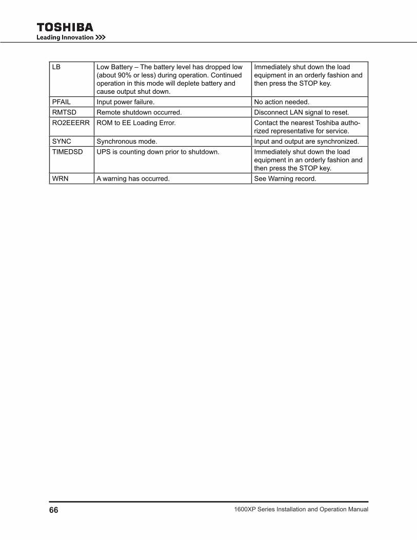
66 1600Xp Series installation and operation manual
lb low battery – the battery level has dropped low (about 90% or less) during operation. Continued operation in this mode will deplete battery and cause output shut down.
immediately shut down the load equipment in an orderly fashion and then press the Stop key.
pFAil input power failure. no action needed. rmtSd remote shutdown occurred. disconnect lAn signal to reset.ro2eeerr rom to ee loading error. Contact the nearest toshiba autho-
rized representative for service.SynC Synchronous mode. input and output are synchronized.timedSd UpS is counting down prior to shutdown. immediately shut down the load
equipment in an orderly fashion and then press the Stop key.
wrn A warning has occurred. See warning record.

671600Xp Series installation and operation manual
UPS Protection System
System Protection Featuresthe following schematic shows the electrical locations of the protection devices on the UpS.
System Protection Functions the following charts show the built-in system fault protection functions on all the UpS models.
BUILT-IN UPS FAULT PROTECTION FUNCTIONS
Protection Item Output Overvoltage Output Undervoltage Output Overload
lCd message OUT-OV OUT-UV OVERLOAD
Cause Control malfunction; chip error
Control malfunction; Fuse opened; load issue overload – Short circuit at load
operation mode After Fault
bypass operation – Chopper and inverter are stopped
inverter ol: transfer to bypass; bypass ol: inverter, chopper
stopped
Audible Alarm yes – Continuous buzzer See Audible Alarm Functions on page 31
Visible Alarm red Fault led on inverter ol: Fault lamp off bypass ol: Fault lamp on
relay Contact Alarm
Fault relay closed bypass relay closed
Fault relay open; inverter ol: bypass relay closed bypass ol: bypass relay open
Auto-retransfer no inverter ol: yes if bypass is ok bypass ol: no
input Abnormal
low battery level
overheating overcurrentCurrent limit
overload
overvoltage/Undervoltage
Output PowerLine Filter Inverter
*Static SwitchIsolation
Transformer
Input Power
Input Fuse
Power Flow
Bypass
* Switches are solid state devices.
MCCBOutput Fuse
Surge Absorber Batteries +
–
Rectifier/Chopper
Negative Bus

68 1600Xp Series installation and operation manual
BUILT-IN UPS FAULT PROTECTION FUNCTIONS (CONT’D)
Protection Item Internal Overheat DC Circuit Overvoltage
DC Circuit Overcurrent
lCd message oVerHeAt dC-oV dC-oC
Cause Fan failure; High ambient temperature Chopper malfunction inverter/chopper fault
operation mode After Fault Shutdown – no output bypass operation – Chopper and inverter are stopped
inverter ol – transfer to bypassAudible Alarm yes – Continuous buzzerVisible Alarm red Fault led onrelay Contact Alarm
Fault relay closed bypass relay closed
Auto-retransfer no
Preventive Maintenance/Parts Replacement
Preventive Maintenancetoshiba 1600Xp Series of uninterruptible power systems have been designed to provide years of trouble-free operation requiring a minimum of preventive maintenance.the best preventive measure that the UpS user can take is to keep the area around the unit, particularly the air inlet vents, clean and free of moisture and dust accumulations. if the atmosphere of the installation site is very dusty, use a vacuum cleaner to periodically remove dust accumulations around and from the unit.
CAUTIONOnly a qualified Toshiba representative should be allowed to perform any routine maintenance or service on this equipment other than those preventive maintenance details which are described directly above this caution.
Cleaning the TouchscreenThe touchscreen display is covered with a protective Teflon coating. It should be cleaned with a clean, damp cotton cloth to avoid scratching the coating.

691600Xp Series installation and operation manual
Parts Replacementthe following list shows recommended intervals for periodic replacement of certain UpS parts:
Aluminum electrolytic 1. capacitors: replace once every 5 years.Fuses: replace once every 7 years.2.
3. Cooling fan: when operated in an ambient temperature of 86 °F (30 °C) to 104 °F (40° C), replace every 3.5 years. when operated in an ambient temperature of less than 86 °F (30 °C) , replace every 5 years.note: the cooling fans are not hot swappable. remove all power from the UpS before replacing the cooling fans.(open the UpS main circuit breaker, disconnect external battery cabinets, and partially slide out the top battery trays enough to open the internal dC power circuit.)`batteries: in order to maintain system reliability, the UpS batteries should be replaced on a 4. regular schedule. to ensure reliable operation, all of the batteries should be replaced at the same time. Use the following chart for replacement:
UPS BATTERY REPLACEMENT
BATT AMB TEMP* AVERAGE LIFETIME68 – 77 °F (20 – 25 °C) Approximately 5 yrs.
86 °F (30 °C) Approximately 3.5 yrs. 95 °F (35 °C) Approximately 2.5 yrs.104 °F (40 °C) Approximately 1.8 yrs.113 °F (45 °C) Approximately 1.25 yrs.
* Continual operation at ambient temperatures above 25 °C will degrade the battery life.
Optional Receptacle Panel Installation Instructions
these are the instructions for installing the optional modular output receptacle panels for the 1600Xp Series UpS. these instructions apply to all UH3-rp-XX panel options.
wArning: the work outlined in these instructions is to be performed only on a completely un-energized UpS system.

70 1600Xp Series installation and operation manual
refer to Figure 1 for location of UpS referenced material. refer to Figure 2 for material referring to the receptacle panel module. there are different panels available depending on the UpS typeform.
Step 1: remove the modular receptacle panel cover plate.
on the rear of the UpS, locate the cover plate for the receptacle panel module interface (see Figure 1).
remove the 6 mounting screws.
remove the cover plate. A square-shaped plug will be exposed.
Step 2: Snap-in output receptacle modular panel.
Carefully mate the square-shaped connector on the UpS to its matching counter part on the rear of the modular panel.
Step 3: mount the receptacle panel.
Attach the screws removed from the cover plate through the mounting holes of the receptacle panels and back into the UpS mounting points.
Figure 1 Figure 2

711600Xp Series installation and operation manual
Optional MB (Maintenance Bypass) Units
The following illustration shows the circuit power flow when the UPS is operating in the optional Mainte-nance bypass mode. the input jumper on the UpS must be set for 240 VAC.
NOTICEensure the UpS is in Static bypass before switching the unit from UpS to maintenance bypass mode or from maintenance bypass to UpS mode. Failure to do so could result in damage to the maintenance bypass switch or the UpS.
this maintenance bypass unit can only be used for 240 V applications. ensure the UpS voltage selector jumper is set to 240 V. See page 13 for the correct 240 V setting.
Internal Maintenance Bypassthe optional internal maintenance bypass is mounted on the rear of the UpS.
internal maintenance bypass instructions:
From inverter mode to maintenance bypass modeturn the rUn/Stop switch to the Stop position on the UpS.1. turn the maintenance bypass Switch to the bypass position. the bypass led should be on and the 2. UpS led should be oFF. the leds are next to the maintenance bypass switch, on the back of the UpS.turn the mCCb input breaker on the UpS to the oFF position. the UpS is now operating in mainte-3. nance bypass mode.
From maintenance bypass mode to inverter modeturn the mCCb input breaker on the UpS to the on position.1. turn the maintenance bypass switch to the UpS position. the UpS led should be on and the bypass 2. led oFF.turn the rUn/Stop switch to the rUn position on the UpS. the UpS is now operating in the UpS 3. mode.
POWER FLOW IN MAINTENANCE BYPASS MODE FOR ALL MODELS
Output Power
Line Filter Inverter
*Static SwitchIsolation
Transformer
Input Power
Input Fuse
Power Flow
Bypass
* Switches are solid state devices.
MCCBOutput Fuse
Surge Absorber Batteries +
–
Rectifier/Chopper
Maintenance Bypass Switch
Negative Bus

72 1600Xp Series installation and operation manual
External Maintenance Bypasswiringthe following connections must be made to the Utility panel and the load panel. the main UpS output is located on the terminal block on the back of the UpS. (tb-4(X1) and tb-7(X3) 240 VAC.)
See the application instructions included with the external maintenance bypass Unit for wiring details.
mAin oUtpUt
Utility pAnel
l1l2ng
loAd pAnel
l1l2ng
UpS
l1l2
g
X1X3ng
mAintenAnCe bypASS

731600Xp Series installation and operation manual
External Layouts/Dimensions/Shipping Weights
Dimensional Data
DIMENSIONAL DATA
3.6 kVA 6 kVA 8 kVA 10 kVA 14 kVA 18 kVA 22 kVA
A 22.1 in.(561 mm)
27.5 in.(698 mm)
28.3 in.(719 mm)
28.3 in.(719 mm)
39.0 in.(991 mm)
39.0 in.(991 mm)
39.0 in.(991 mm)
b 10.0 in.(254 mm)
10.0 in.(254 mm)
13.0 in.(330 mm)
13.0 in.(330 mm)
17.5 in.(445 mm)
17.5 in.(445 mm)
17.5 in.(445 mm)
C 34.0 in.(863 mm)
34.0 in.(864 mm)
34.9 in.(886 mm)
34.9 in.(886 mm)
36.1 in.(917 mm)
36.1 in.(917 mm)
36.1 in.(917 mm)
d 19.7 in.(500 mm)
25.1 in.(637 mm)
25.7 in.(654 mm)
25.7 in.(654 mm)
35.6 in.(904 mm)
35.6 in.(904 mm)
35.6 in.(904 mm)
e 2.4 in.(61 mm)
2.4 in.(61 mm)
2.6 in.(65 mm)
2.6 in.(65 mm)
3.4 in.(87 mm)
3.4 in.(87 mm)
3.4 in.(87 mm)
Electrical Conduit Knock-out Data
ELECTRICAL CONDUIT KNOCK-OUT HOLE SIZES (DIAMETER)
3.6 kVA 6 kVA 8 kVA 10 kVA 14 kVA 18 kVA 22 kVA3 ea. back/
bottom 1.125 in.
(28.575 mm)
3 ea. back/bottom
1.125 in. (43.69 mm)
2 ea. back/ 3 ea. bottom
1.72 in. (43.69 mm)
2 ea. back/ 3 ea. bottom
1.72 in. (43.69 mm)
4 ea. back/bottom1.72 in.
(43.69 mm)
4 ea. back/bottom1.72 in.
(43.69 mm)
4 ea. back/bottom1.72 in.
(43.69 mm)
– –1 ea. back
1.5 in. (38.1 mm)
1 ea. back 1.5 in.
(38.1 mm)– – –
Unit and Shipping Weights
ModelUnit Weight Shipping Weight
Pounds Kilograms Pounds Kilograms3.6 kVA 250 113 325 1476 kVA 288 130 395 1798 kVA 466 211 533 242
10 kVA 491 223 527 23914 kVA 7841 3551 8351 3761
18 kVA 7841 3551 9041 4101
22 kVA 7841 3551 9041 4101
Subject to change without notice.1.

74 1600Xp Series installation and operation manual
external layout for 3.6kVA and 6kVA units
remoteye iii
rS232 port
remote Contacts port (male)
terminal block Cover
mCCb

751600Xp Series installation and operation manual
SNMP Port(Remote -Eye III
Slot)
SNMP Port(Remot -Eye III
Slot)

76 1600Xp Series installation and operation manual

771600Xp Series installation and operation manual
Index
A
AC input mode 29
Altitude 20, 23
Application 5
Audible alarm 5, 58, 59
functions 31
Automatic retransfer 23
B
backup mode 30
battery
backup mode 30, 31
backup time 19, 22, 26, 30
disposal 6
lifetime 23
low-voltage tolerances 26
manufacturer 24
pack 24
pack (quantity) 24
recharge tolerances 28
recharging 28
replacement 3, 23, 60
voltage drop 5, 16, 30
battery Cabinet 15
buzzer volume 23
bypass
disable 23
mode 27, 29, 37
overload capacity 22
switch 23
C
Cable size 14
capacitors 60
Common-mode noise 5, 22
Communication interface 16
Conduit knock-out, sizes 64
Cooling fan 60
D
data. See data display Screens, data Setting
Screens
db9 Connector
female pinouts 18
male pinouts 16
dimensional data 64, 66
display
Adjustment 32
disposal 6
E
emergency power off (epo) function 14, 30
enclosure 24
environment 6, 23
event data Storage 23
F
fan 24, 59
Fault
protedtion functions 58, 59
signal 16, 29, 31
Frequency

78 1600Xp Series installation and operation manual
AUto/mAn 22
input 22
output 22
warning 10
Front panel layout 32, 33, 36, 38, 39
G
ground
importance of, 7
terminals 14
ground
rS-232C 18
grounding 9
H
Humidity 23
humidity 6
I
input Capacity 22
input Frequency 22
warning 10
input Voltage 19, 20, 21, 22, 23, 24
requirements 10
inspection 6
installation precautions 7
interface
communications 16, 17, 18
receptacle panel module 61
rS232 ASCii 23
inverter overload Capacity 22
K
keypad
controls 38
password 39
keys 34
knock-out, sizes 64
L
labels, warning 11
lifetime
battery 23, 60
capacitors, Aluminum electrolytic 60
fan, cooling 60
fuses 60
liquid Crystal display (lCd) Functions 32
low Voltage tolerance 26
M
mAin tab 36
maintenance bypass 62, 63
maintenance bypass, voltage restrictions 62
maintenance bypass Unit 62
maximum ambient operating temperature 3
mimic display 40
mode
AC input 29
monitor tab 40
N
normal input power supply 16
O
off 32
operation modes. See modes

791600Xp Series installation and operation manual
output disconnect 3
overload Capacity 22
overvoltage
dC 59
output 58
P
parameters
changing 44, 46
passwords 39
peak output Current 22
power backup 5
power Conditioning 5
power factor
output, rated load 26
power factor
input 22
output, rated load 22
power failure signal 16, 17
precautions 10
preventive maintenance 59
protection System 58
R
real time Clock 23
receptacle panels 60, 61
recharge time 22, 28
reCordS tab
Fault messages 53
mode messages 56
Status messages 56
warning messages 54
relay switch 16
remote contacts interface 16
remote Switch 14
remoteye network Card 18
restrictions on UpS use 10
rS-232C 18
run 32
S
Safety instructions 1, 3Schedule operation 23
Security
access 39
passwords 39
Security access 46
SettingS tab 42
parameters 46
Shipping weight 64
Shutdown voltage 26
Signal Function
rS-232C 16
Signal words 2
Size
battery packs 24
UpS dimensions 24
wire 14
Specifications 19
Starting the UpS 27, 37
Startup, initial 25
Stopping the UpS 27, 32
Stop Signal operation 17
Storage 6, 23
temperature 23

80 1600Xp Series installation and operation manual
T
terminal block 13, 15
theory of operation 5
torque, tightening 14
touchscreen
calibrate 45
control icons 34
keypad 38
layout 33
menu tree 36
mimic display 40
passwords 39
screen disable 37
U
Unpacking 6
UpS
discharge process 26, 30
UpS Connections 13
UpS functional overview 5
UpS stop signal input 16, 17
V
ventilation 10
Voltage transient 22
Volume, buzzer. See buzzer Volume
W
warning labels 11
warranty d, e, 6weights, shipping 64
weights, UpS 64


INDUSTRIAL DIVISION13131 west little york road, Houston, texas 77041tel (713) 466-0277 Fax. (713) 466-8773US (800) 231-1412 Canada (800) 872-2192 mexico 01/800/527-1204www.toshiba.com/ind
printed in the U.S.A.