16-port hpna (enhanced) switch with snmp...
TRANSCRIPT
11216M-10
16-Port HPNA (Enhanced) Switch with SNMP Management

21216M-10
FCC Certifications This Equipment has been tested and found to comply with the limits for a Class A digital device, pursuant to part 15 of the FCC Rules. These limits are designed to provide reasonable protection against harmful interference when the equipment is operated in a commercial environment. This equipment generates, uses, and can radiate radio frequency energy and, if not installed and used in accordance with the instruction manual, may cause harmful interference to radio communications. Operation of this equipment in a residential area is likely to cause harmful interference in which case the user will be required to correct the interference at his own expense. This device complies with Part 15 of the FCC Rules. Operation is subject to the following two conditions: (1) this device may not cause harmful interference, and (2) this device must accept any interference received; including interference that may cause undesired operation. CE Mark Warning This equipment complies with the requirements relating to electromagnetic compatibility, EN 55022 class A for ITE, the essential protection requirement of Council Directive 89/336/EEC on the approximation of the laws of the Member States relating to electromagnetic compatibility. Company has an on-going policy of upgrading its products and it may be possible that information in this document is not up-to-date. Please check with your local distributors for the latest information. No part of this document can be copied or reproduced in any form without written consent from the company. Trademarks: All trade names and trademarks are the properties of their respective companies. Copyright © 2004, All Rights Reserved. Document Version: 1.0
31216M-10
Table of Contents Unpacking Information ................................................................................................. 5 Introduction to 16-Port HPNA manageable Switch.................................................... 6
General Description................................................................................................ 6 Key Features........................................................................................................... 7 The Front Panel ...................................................................................................... 8
LEDs Definition............................................................................................ 8 Power LED .......................................................................................... 8 Status1 LED......................................................................................... 8 Status2 LED......................................................................................... 8 Management LED................................................................................ 8 Port LEDs (HPNA).............................................................................. 8 Port LEDs (Ethernet ports) ................................................................. 9 POST/ Factory RESET Button........................................................... 10 Console Port...................................................................................... 11
The Rear Panel ..................................................................................................... 11 Power Receptacle........................................................................................ 11
Installing 16-Port HPNA manageable Switch............................................................ 12 Desktop Installation.............................................................................................. 12 Rack-mount Installation ....................................................................................... 13
Management Guide...................................................................................................... 14 Console Port (Out-of-band) connection ............................................................... 15 In-Band Connections (Web Browser / Telnet)...................................................... 16
Starting a Telnet Session ............................................................................. 16 Starting a Web Browser Session ................................................................. 16 The User Interface ...................................................................................... 16 Ports ............................................................................................................ 16
Information........................................................................................ 16 Configuration .................................................................................... 17 Set up Name ...................................................................................... 17 Set up Admin..................................................................................... 17 Set up Speed ...................................................................................... 18 Set up Self Adjusting Mode............................................................... 18 Set up TX Power and RX Noise........................................................ 19 Set up Bandwidth Limitation............................................................. 19 Set up CRC Threshold....................................................................... 20
System Information..................................................................................... 21 Network configure ...................................................................................... 22 Ports Info/Configure ................................................................................... 23 Port name search......................................................................................... 24 VLAN Table................................................................................................ 25
Create VLAN entry ........................................................................... 25 VLAN Port Member configuration ................................................... 26
PVID& Ingress filter................................................................................... 28 To change the PVID .......................................................................... 29 To Enable/Disable Ingress Filtering .................................................. 29
Security ....................................................................................................... 30

41216M-10
Device configuration ......................................................................... 30 HPNA ports ....................................................................................... 32
SNMP ......................................................................................................... 34 Community ........................................................................................ 34 Trap Manager.................................................................................... 35 Trap Filtering .................................................................................... 37
IGMP Snooping .......................................................................................... 38 MAC Search ............................................................................................... 38 Over-Heat Warning ..................................................................................... 38
Product Specifications ................................................................................................. 39
51216M-10
Unpacking Information
Thank you for purchasing the 16-Port HPNA Manageable Switch. Before you start, please check all the contents of this package.
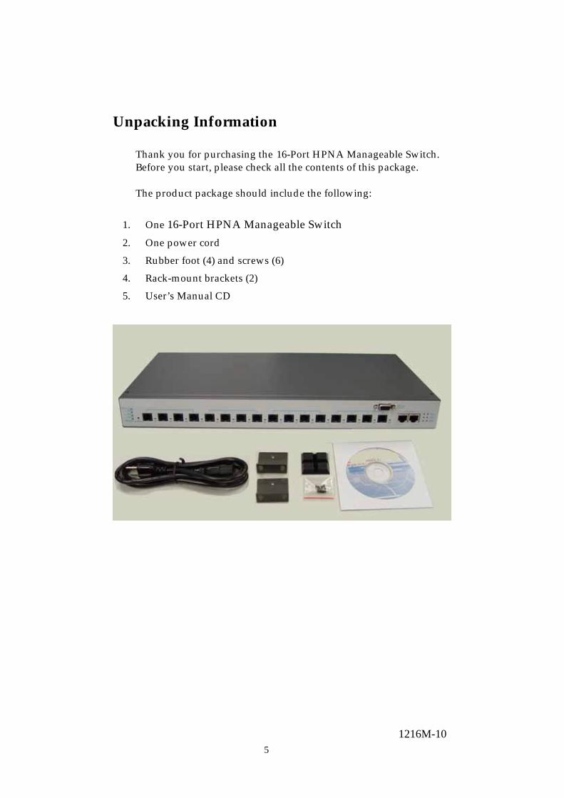
The product package should include the following:
1. One 16-Port HPNA Manageable Switch
2. One power cord
3. Rubber foot (4) and screws (6)
4. Rack-mount brackets (2)
5. User’s Manual CD
61216M-10
Introduction General Description
The device is a powerful and innovative Normal/Enhanced HPNA Manageable switch hub, with 16 ports 1Mbps switching ports and two 10/100Mbps Fast Ethernet switching ports. It is ideal to deliver a dedicated 1Mbps connection for each attached home network or a single hotel room.
The 1Mbps HPNA is a new technology that provides the
network connections through the most widespread telephone wires with no impact on current voice communication. Therefore, users do not need to setup the new network cables and share the network resources. HPNA technology becomes more and more important especially the multi-PC home environment is booming.
With rich management features, the device can be easily
managed by any SNMP manager and web browser. This is very useful for system administrator to remote control and monitor each connected room or house whenever there is any malfunction happen. The user-friendly graphical interface makes the management as straightforward as possible.
Store-and-forward switching mode promises the low latency
and eliminates all the network errors, including runt and CRC error packets. The switching hub is plug-n-play and fully compliant with all kinds of network protocols. Moreover, the rich diagnostic LEDs on the front-panel provide the operating status of individual port and whole system.

71216M-10
Key Features 2 10/100BASE-TX Fast Ethernet port Support 16 independent HPNA ports Wire speed layer 2 switching 4M bits packet switching 2M bits control data, including the Switching address and
VLAN table Prevents packet loss with back pressure and 802.3x flow control Store-and-forward forwarding scheme Error packet filtering Support 12K MAC entries Support up to 255 VLAN table entries Support remote upgrade function Support 2MByte Flash EPROM for code upgrade Support 8M bytes SDRAM for run time data storage Provides wide range of management tools – Web, SNMP,
Console and Telnet. Internal switching power supply (90-264Vac/47-440Hz) Operating temp. 0℃ ~ 50℃(320 ~ 1220F) Humidity: 10 ~ 90 % System temperature sensor Over-heat warning
81216M-10
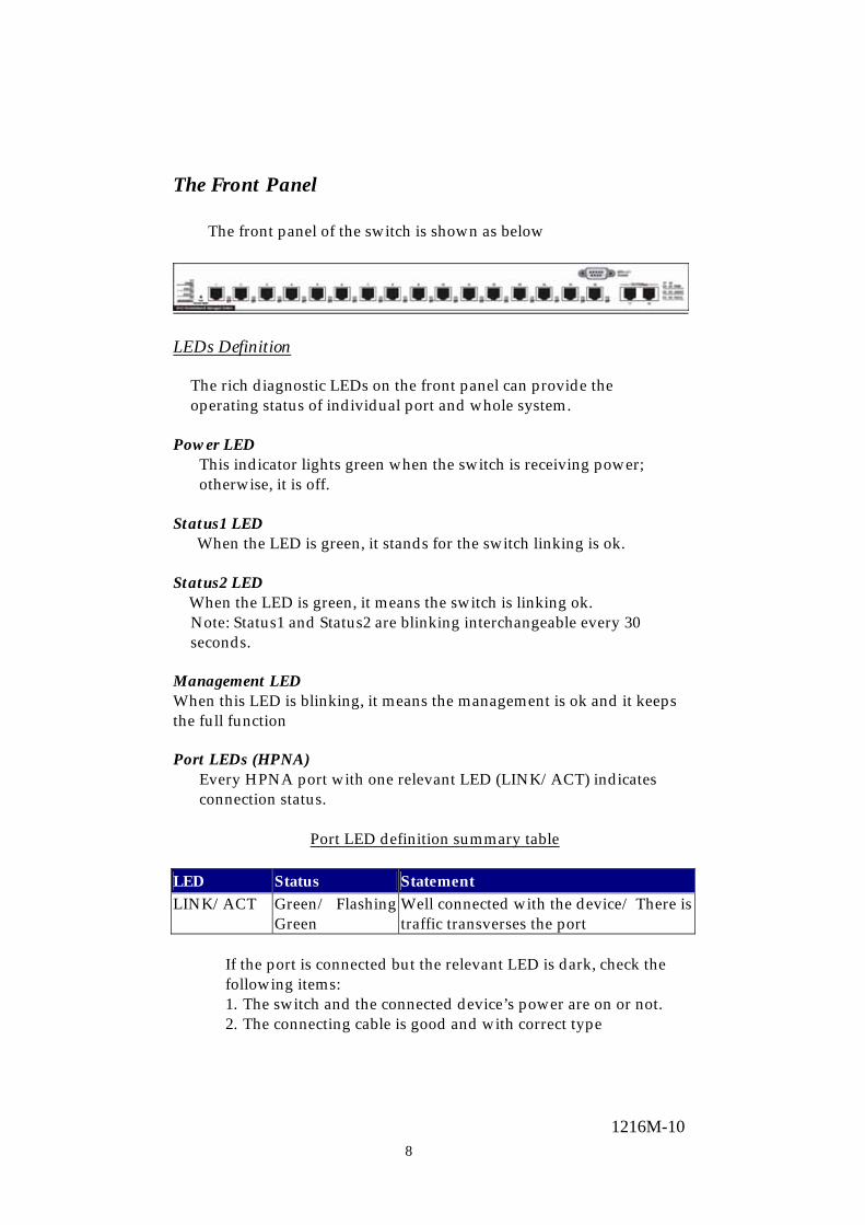
The Front Panel
The front panel of the switch is shown as below
LEDs Definition
The rich diagnostic LEDs on the front panel can provide the operating status of individual port and whole system.
Power LED
This indicator lights green when the switch is receiving power; otherwise, it is off.
Status1 LED When the LED is green, it stands for the switch linking is ok.
Status2 LED When the LED is green, it means the switch is linking ok.
Note: Status1 and Status2 are blinking interchangeable every 30 seconds.
Management LED When this LED is blinking, it means the management is ok and it keeps the full function Port LEDs (HPNA)
Every HPNA port with one relevant LED (LINK/ACT) indicates connection status.
Port LED definition summary table
LED Status Statement LINK/ACT Green/ Flashing
Green Well connected with the device/ There is traffic transverses the port
If the port is connected but the relevant LED is dark, check the following items: 1. The switch and the connected device’s power are on or not. 2. The connecting cable is good and with correct type

91216M-10
3. The cable is firmly seated in its connectors in the switch and in the associated device
4. The connecting device, including any network adapter is well installed and functioning
5. Confirm the device is implemented within the scope of operative without interference
Port LEDs (Ethernet)
Port LEDs indicators locate on the front panel for showing the operating status of 10/100Mbps Fast Ethernet switching ports.
FDX/COL LED
A collision occurs when two stations within a collision domain attempt to transmit data at the same time. Intermittent flashing amber of the collision LED is normal; the contending adapters resolve each collision by means of a wait-then-retransmit algorithm. Frequency of collisions is an indicator of heavy traffic on the network. If the FDX/COL lights amber it means the port is under full-duplex operation or dark for half-duplex mode. The following table is a summary of LAN Port LEDs.
LED Operation SPEED 100Mbps (Green), 10Mbps (Off) LINK/ACT Link is present (Green), Activity (Blinking Green)
FDX/COL Full-Duplex (Amber), Half-Duplex (Off), Collision (Blinking Amber)
LINK/ACT LED
Every port has a LINK/ACT LED. Steady green (link state) indicates that the port has good linkage to its associated devices. Flashing green indicates that the port is receiving or transmitting data between its associated devices.
Speed LED Link/Activity LED Status
Off Off No Connection Off Green Connect as 10Mbps Green Green Connect as 100Mbps
SPEED LED
The SPEED LED indicates the link speed of each port. If the LED lights green then the connection speed is 100Mbps, off for 10Mbps.

101216M-10
POST/ Factory RESET Button
POST: Press it at the beginning of power supplying, system will run self-test procedure.
Factory Reset:
To restore the default value such as IP, VLAN, etc, press it during the operation.

111216M-10
Console Port The RS-232 console is an interface for connecting a terminal directly. Through the console port, it provides rich diagnostic information includes network statistics, link status and system setting. The operating mode of the console port is:
DCE 9600 (Fix baud rate) n (No parity checking) 8 (8 Data bits) 1 (1 stop bit) None (No flow control)
You can use a normal RS-232 cable and connect to the console port on the device. After the connection, you can run any terminal emulation program (Hyper Terminal, Winterm, Telix, etc.) to enter the startup screen of the device. All the detail software operation, please refer to “Console port (out-of-band) connection” session of chapter 4. The Rear Panel The rear panel of the switch is shown as below
Power Receptacle For compatibility with electric service in most areas of the world, the switch’s power supply automatically adjusts to line power in the range 90-264Vac/47-440Hz. Plug the female end of the power cord firmly into the receptacle on the rear panel of the switch. Plug the other end of the power cord into an electric service outlet then the power will be ready.
121216M-10
Hardware Installation
This switch can be placed directly on your desktop, or mounted in a rack. If you install the device in a normal-standalone standard, the switch is an Intelligent Switch, and users can immediately use most of the features simply by attaching the cables and turning the power on. In this case, any managerial proceedings are effective only in the range of the switch. After management stacking, you can enjoy the powerful management functions and control the whole system.
Desktop Installation
For desktop installation, the switch needs to put on a clean, flat desk or table close to a power outlet. Plug in all network cables and the power cord, and then the system is ready to work.
Before installing the switch, you must ensure:
1. It is accessible and cables can be connected easily 2. Cabling is away from:
• Sources of electrical noise such as radios, transmitters and broadband amplifiers
• Power lines and fluorescent lighting fixtures. 3. Keep water or moisture off 4. Airflow around the unit and through the vents in the side of
the case is great for heat radiation (company recommends that you provide a minimum of 25 mm clearance)
To prolong the operational life of your units:
1. Never stack unit more than eight sets high if freestanding 2. Do not place objects on top of any unit or stack 3. Do not obstruct any vents at the sides of the case
131216M-10
Rack-mount Installation
The switch may standalone, or may be mounted in a standard 19-inch equipment rack. Rack mounting produces an orderly installation when you have a number of related network devices. The switch is supplied with rack mounting brackets and screws. These are used for rack mounting the unit.
Rack Mounting the Switch in the 19-inch rack:
1. Disconnect all cables from the switch before continuing. 2. Place the unit the right way up on a hard, flat surface with the
front facing toward you. 3. Locate a mounting bracket over the mounting holes on one side
of the unit. 4. Insert the screws and fully tighten with a suitable screwdriver. 5. Repeat the two previous steps for the other side of the unit. 6. Insert the unit into the 19" rack and secure with suitable screws
(not provided). 7. Reconnect all cables.
141216M-10
Management Guide This section instructs you how to enter and proceed the advanced management capability, which can be accessed by RS-232 serial port (out-of-band) on the rear panel or by Telnet session / Internet Browser over the network (in-band). The management functions such as:
· Port Information/configuration/Statistic/Location Search/Duplex mode/Flow Control
· SNMP parameters · IGMP snooping · 802.1Q/Port Group VLAN · Address Table · Upgrade system firmware · Reboot system, etc…
Factory Default value:
IP: 10.0.0.1 Subnet Mask: 255.0.0.0 Default Gateway: 10.0.0.254
Standalone switch can be managed using either a standard Web Browser or a Telnet session from any computer attached to the network. The SNMP management feature also permits the switch to be managed from any SNMP network management station running a network management program. To manage the Standalone switch: Access the switch with its IP address “10.0.0.1” (factory default value) Privilege levels: “root”: root can do any configuration includes changing password
and enable/disable management capability via console port. The default password of root is “superuser”
“admin”: admin can do any configuration except changing password. The default password of admin is “admin”
“guest”: guest can view whole the runtime information only, moreover, access to Web management interface is not allowed. The default password is “guest”
151216M-10
Console Port (Out-of-band) connection After attaching a RS-232 cable (Straight-through) to the serial port of a PC running a terminal emulation program, press “Enter” key then login screen appears. Enter your username and password to login the management console. Note: The management functions of console program are exactly the same with web-based management interface but in text mode. For further operation, please refer to ’Starting a Web Browser Session’.
Attention:1. The factory default value of UserName and Password is “admin”
2. For detail console port configurations, please refer to “Console Port” in chapter 2
3. System configurations via the Console Port only will be allowed by the way of master device
161216M-10
In-Band Connections (Web Browser / Telnet) To manage the switch through in-band access, you should configure the management station with an IP address and subnet mask compatible with your clustering switch.
Starting a Telnet Session To access the switch through a Telnet session:
1. Sure of the switch is configured with an IP address and the switch is reachable from a PC
2. Start the Telnet program on a PC and connect to the switch
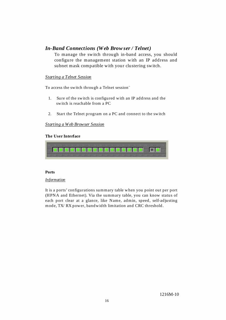
Starting a Web Browser Session The User Interface
Ports
Information It is a ports’ configurations summary table when you point out per port (HPNA and Ethernet). Via the summary table, you can know status of each port clear at a glance, like Name, admin, speed, self-adjusting mode, TX/RX power, bandwidth limitation and CRC threshold.
171216M-10
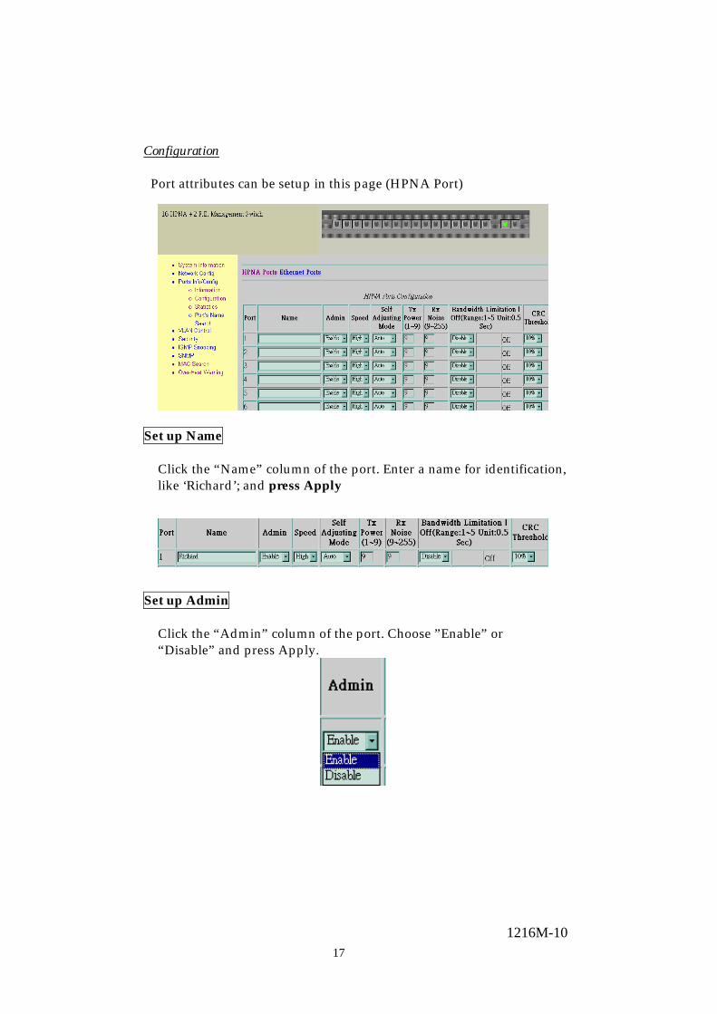
Configuration Port attributes can be setup in this page (HPNA Port)
Set up Name
Click the “Name” column of the port. Enter a name for identification, like ‘Richard’; and press Apply
Set up Admin
Click the “Admin” column of the port. Choose ”Enable” or “Disable” and press Apply.
181216M-10
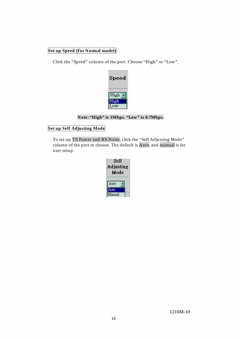
Set up Speed (For Normal model)
Click the “Speed” column of the port. Choose “High” or “Low”.
Note: “High” is 1Mbps. “Low” is 0.7Mbps. Set up Self Adjusting Mode
To set up TX Power and RX Noise, click the “Self Adjusting Mode” column of the port to choose. The default is Auto, and manual is for user setup.
191216M-10
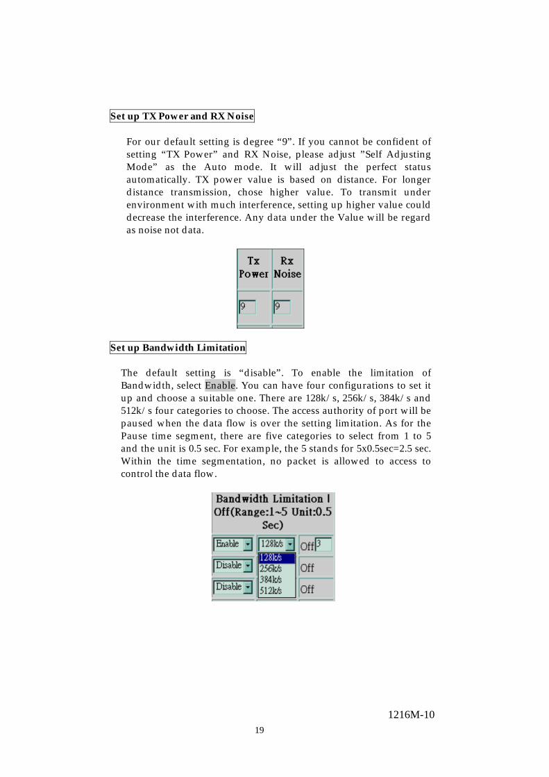
Set up TX Power and RX Noise For our default setting is degree “9”. If you cannot be confident of setting “TX Power” and RX Noise, please adjust ”Self Adjusting Mode” as the Auto mode. It will adjust the perfect status automatically. TX power value is based on distance. For longer distance transmission, chose higher value. To transmit under environment with much interference, setting up higher value could decrease the interference. Any data under the Value will be regard as noise not data.
Set up Bandwidth Limitation
The default setting is “disable”. To enable the limitation of Bandwidth, select Enable. You can have four configurations to set it up and choose a suitable one. There are 128k/s, 256k/s, 384k/s and 512k/s four categories to choose. The access authority of port will be paused when the data flow is over the setting limitation. As for the Pause time segment, there are five categories to select from 1 to 5 and the unit is 0.5 sec. For example, the 5 stands for 5x0.5sec=2.5 sec. Within the time segmentation, no packet is allowed to access to control the data flow.

201216M-10
Set up CRC Threshold
User could adjust the column of each port including three modes to choose, 1%, 5% and 10%. The higher percentage makes the trap easier.

211216M-10
System Information Information From these columns, you can get the detailed information about the Software and Hardware. Also, you can have your system setting.
Note. The version will be different from the one of final goods.
221216M-10
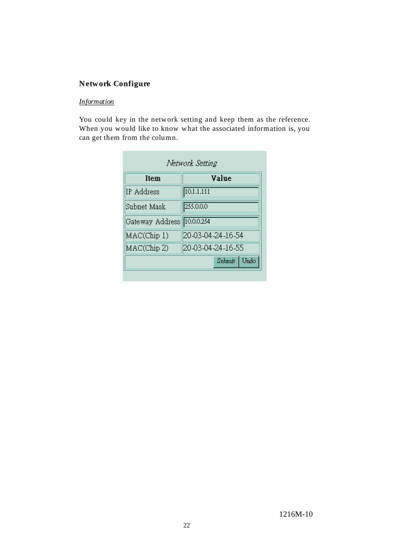
Network Configure
Information You could key in the network setting and keep them as the reference. When you would like to know what the associated information is, you can get them from the column.

231216M-10
Ports Info/Configure Information For this item, you can know the information of ports, configuration, statistics and port’s name search. It provides you an effective way to know the status.
241216M-10
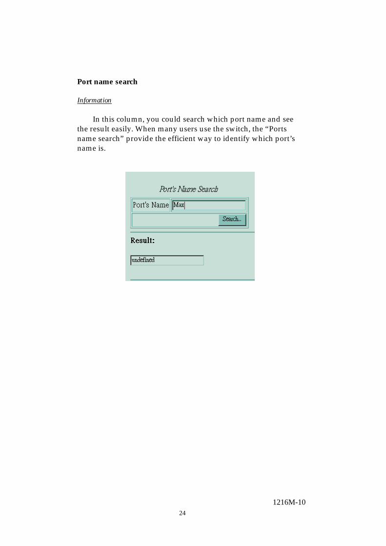
Port name search Information In this column, you could search which port name and see the result easily. When many users use the switch, the “Ports name search” provide the efficient way to identify which port’s name is.

251216M-10
VLAN Table
Information The VLAN is a group of ports that may spread around the
network but communicate as though they belong to one subnet. By using IEEE 802.1Q compliant VLAN, all ports can be reorganized into separate broadcast domains for security reasons and reduce bandwidth occupation instead of using routers to divide whole network into subnets. It produces cleaner network environment by reducing broadcast traffic and simplify network management by allowing you to move devices to another VLAN without changing physical connections.
802.1Q VLAN
Before enabling 802.1Q VLAN , pay attention to: • All ports are default to VLAN 1 and assigned PVID 1 • All the ports of a Aggregation Group must be treated as an
integer when added to/deleted from a VLAN Create VLAN entry
This screen is used to Add / Remove VLAN and up to 255 groups with VID 1~4094. The VLAN groups that have been created are all listed here.
To create a new VLAN Entry
1. Specify the name for the new VLAN Entry (VLAN name is only used for identification)
2. Enter a number (VLAN ID) and Name for the new VLAN group
3. Click <<Add button to create the new VLAN Entry
261216M-10
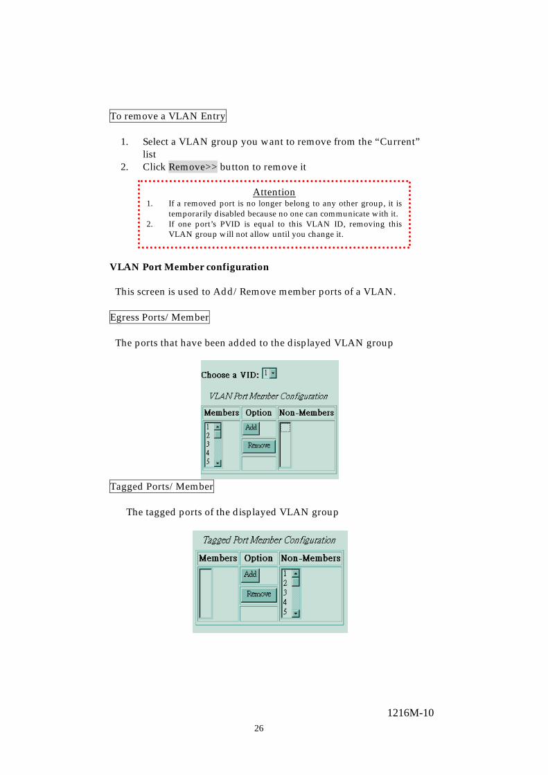
To remove a VLAN Entry
1. Select a VLAN group you want to remove from the “Current” list
2. Click Remove>> button to remove it
VLAN Port Member configuration
This screen is used to Add/Remove member ports of a VLAN.
Egress Ports/Member
The ports that have been added to the displayed VLAN group
Tagged Ports/Member
The tagged ports of the displayed VLAN group
Attention 1. If a removed port is no longer belong to any other group, it is
temporarily disabled because no one can communicate with it. 2. If one port’s PVID is equal to this VLAN ID, removing this
VLAN group will not allow until you change it.
271216M-10
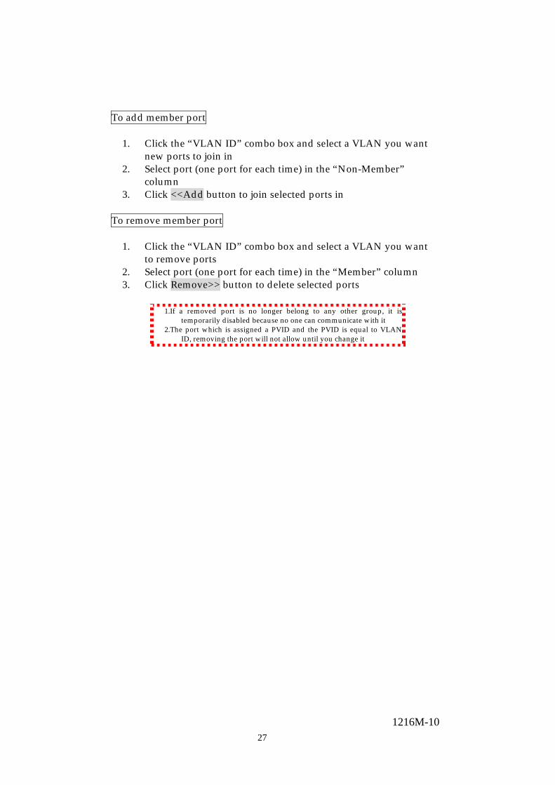
To add member port
1. Click the “VLAN ID” combo box and select a VLAN you want new ports to join in
2. Select port (one port for each time) in the “Non-Member” column
3. Click <<Add button to join selected ports in To remove member port
1. Click the “VLAN ID” combo box and select a VLAN you want to remove ports
2. Select port (one port for each time) in the “Member” column 3. Click Remove>> button to delete selected ports
1.If a removed port is no longer belong to any other group, it is
temporarily disabled because no one can communicate with it 2.The port which is assigned a PVID and the PVID is equal to VLAN
ID, removing the port will not allow until you change it

281216M-10
PVID& Ingress filter
When the VLAN-enabled switch receives an untagged packet, the packet will be sent to the port’s default VLAN according to the PVID (port VLAN ID) of the receiving port.

291216M-10
To change the PVID 1. Double click the “PVID” column of a port 2. Input a new VLAN ID (1~4094) 3. Press “Enter” to submit the value 4. Click Apply button to apply it Note: 1. All the ports are default as members of VLAN 1 and assigned PVID 1 2. The port which was assigned a PVID and the PVID is equal to VLAN ID, removing the
port will not allow until you change it 3. Inherently, a port will join the VLAN of its PVID, and if the VLAN does not exist, system
will create it
To Enable/Disable Ingress Filtering
When one packet comes in from Port X to VLAN Y, but Port X is not a member of VLAN Y Ingress Filter Enabled:The filter checks the packet and detects Port X
does not belong to the VLAN Y, the Ingress Filter discards the packet.
Ingress Filter Disabled:All the packets destined to VLAN Y are all unobstructed.
Click the “Ingress Filtering” column of a port and select ‘Enable’ to activate Ingress Filter

301216M-10
Security Information
To configure the device and ports access authority limitation of SWITCH Web-based user interface/telnet console, click the security option on the main menu.
Security page
Device configuration
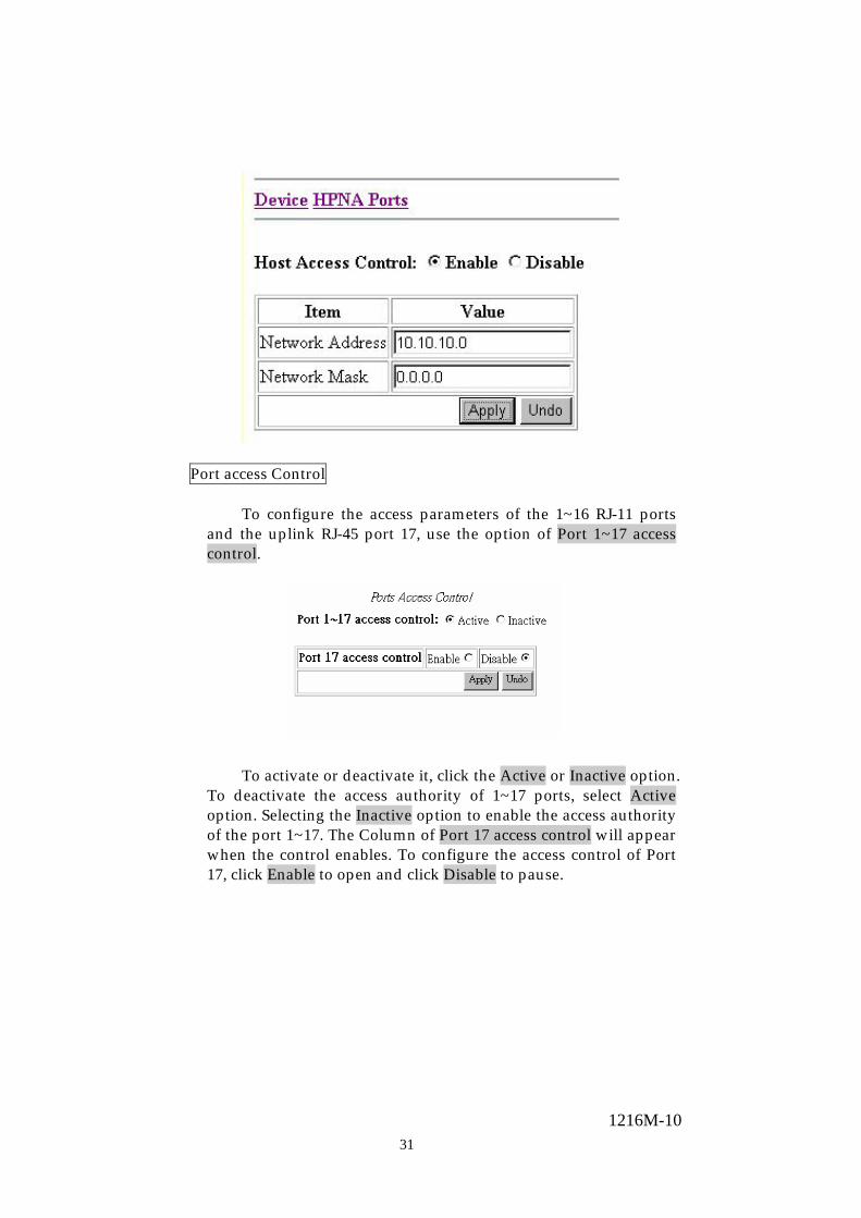
Host access control
On the Device option, it contains two parts, one is Host access control, and another is Port access control. The host access control provides three options. On Host access control option, user defines the subnet IP that is cable to access the SWITCH. The user is able to activate or deactivate the function of access authority limitation by click Enable or Disable.
The Column of Value will appear when the control enables. Type the Network IP address in the column of Network address and the subnet mask value in the column of Network Mask, and then click the Apply gray button to save the change. Click Undo button to erase the wrong key-in value.
311216M-10
Port access Control
To configure the access parameters of the 1~16 RJ-11 ports and the uplink RJ-45 port 17, use the option of Port 1~17 access control.
To activate or deactivate it, click the Active or Inactive option. To deactivate the access authority of 1~17 ports, select Active option. Selecting the Inactive option to enable the access authority of the port 1~17. The Column of Port 17 access control will appear when the control enables. To configure the access control of Port 17, click Enable to open and click Disable to pause.
321216M-10
HPNA ports
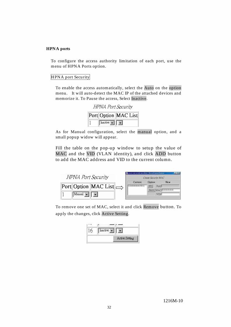
To configure the access authority limitation of each port, use the menu of HPNA Ports option.
HPNA port Security
To enable the access automatically, select the Auto on the option menu. It will auto-detect the MAC IP of the attached devices and memorize it. To Pause the access, Select Inactive.
As for Manual configuration, select the manual option, and a small popup widow will appear. Fill the table on the pop-up window to setup the value of MAC and the VID (VLAN identity), and click ADD button to add the MAC address and VID to the current column.
To remove one set of MAC, select it and click Remove button. To apply the changes, click Active Setting.

331216M-10
For the sack of user-friendly, Mac-list will memorize the Mac IP of attached devices up to eight sets. The Mac IP list provides a reference log for attached device MAC address.
Attention: Due to data processing, the program will delay for one or two minutes when applying new security setting
341216M-10
SNMP Simple Network Management Protocol (SNMP) is a
communication protocol for managing devices on a network. It is commonly used for network administrators to communicate with multiple devices (hub, switch, router etc…) for configuring and monitoring while convenient for troubleshooting but no miscellaneous platform consideration. The built-in SNMP is an agent, which watches the status of it self. The Network Management Station (A computer attached to network with SNMP management program well installed) can be used to access it. Community
A valid entry of Community String and IP Address is for
authentication to login to the SNMP agent for configuration. Moreover, the community capacity can up to 3 sets and only by the way of specified IP address here will be allowed to access the agent. One entry consist of IP address “0.0.0.0” will allow the ones who know the community string to access the agent (with Read-Only access right) without limitation.
To add a community
1. Input a name as a community string for authentication in the “Community String” field (ex: administrator)
2. Enter the IP address in the “IP address” field you allow to access from (ex: 192.168.1.22)
3. Click the “Access Mode” combo box and select a authority (Read-Only / Read-Write)
4. Click <<Add button to add this entry
To Remove a Trap manager
1. Select the Trap manager you want to remove from the “Current” list
2. Click Remove>> button to remove it
351216M-10
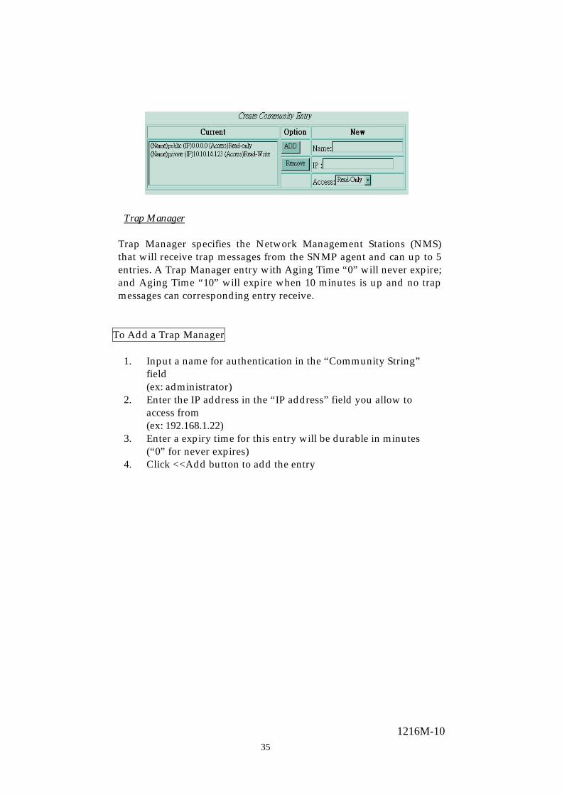
Trap Manager Trap Manager specifies the Network Management Stations (NMS) that will receive trap messages from the SNMP agent and can up to 5 entries. A Trap Manager entry with Aging Time “0” will never expire; and Aging Time “10” will expire when 10 minutes is up and no trap messages can corresponding entry receive.
To Add a Trap Manager
1. Input a name for authentication in the “Community String” field (ex: administrator)
2. Enter the IP address in the “IP address” field you allow to access from (ex: 192.168.1.22)
3. Enter a expiry time for this entry will be durable in minutes (“0” for never expires)
4. Click <<Add button to add the entry

361216M-10
To Remove a Trap manager
1. Select the community you want to remove from the “Current” list
2. Click Remove>> button to remove it
371216M-10
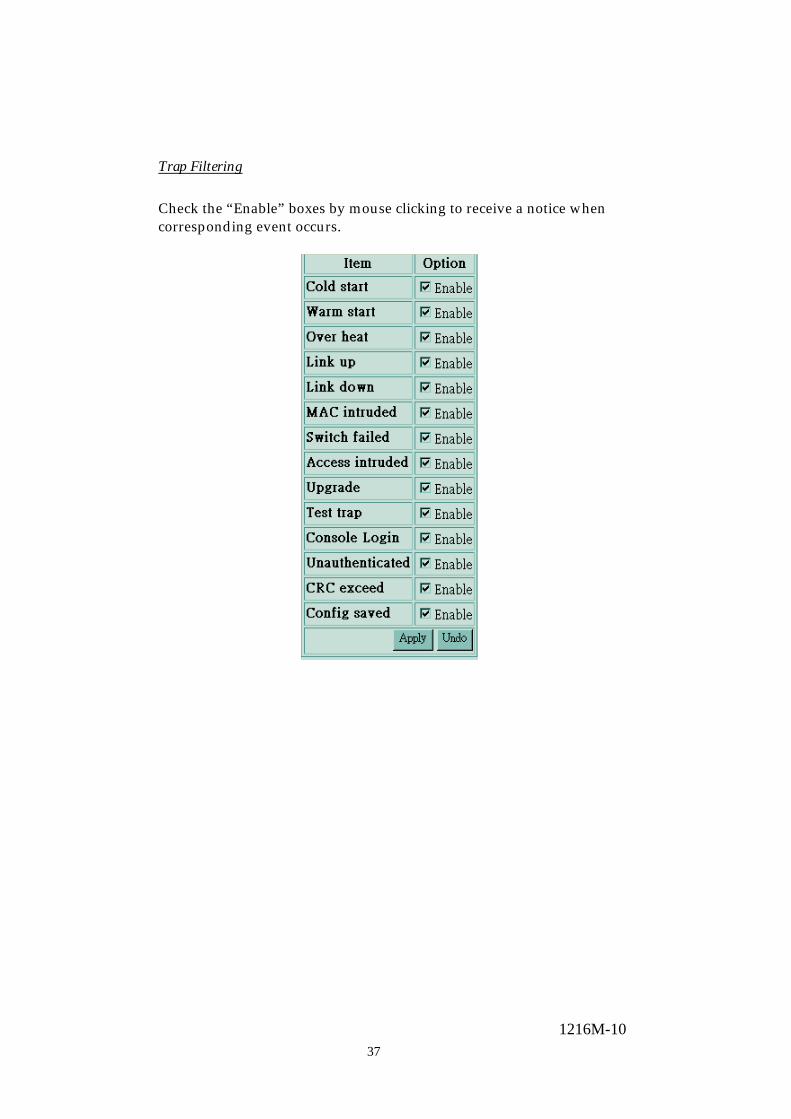
Trap Filtering
Check the “Enable” boxes by mouse clicking to receive a notice when corresponding event occurs.

381216M-10
IGMP Snooping
Multicasting is widely used to support multi-media applications such as video conferencing. The multicasting simply broadcasts its services to the group of a network instead of establishing connections separately with every host that subscribed the services. With no Multicast Filtering-aware switches, a multicast server may floods broadcast-data overall the broadcast domain and wastes a lot of bandwidth. The Internet Group Management Protocol (IGMP) snooping uses the protocol to make switches join/leave multicast group and interacts switches to optimize the network performance by monitoring the IGMP packets and forward to the ports containing multicast hosts or switches. This will efficiently reduce the multicast traffic rather than flooding overall network. IGMP snooping is more and more important especially when the multi-media demand is booming.
Note: As IGMP Snooping only operates under 802.1Q VLAN mode, please change VLAN mode from Port Group VLAN to 802.1Q VLAN before enabling IGMP Snooping.
MAC Search
To search for a specific MAC IP, use Mac search to save time.
Over-Heat Warning
To set up over heat alarm standard and monitor the system temperature, use Over-heat warming setting.

391216M-10
Product Specifications
Standard
IEEE802.3 10BASE-T IEEE802.3u 100BASE-TX IEEE802.3x full-duplex operation and flow control IEEE 802.1 Q VLAN
Interface
16 * HPNA RJ-11 ports 2 * 10/100Mbps Fast Ethernet Ports 1 * RS-232 console port 1 * post/factory reset button
Cable Connections
RJ-45 (10BASE-T): Category 3,4,5 UTP/STP RJ-45 (100BASE-TX): Category 5 UTP/STP 1Mbps Home Net: Twisted-pair telephone wires
LED indications
System Power; Status 1; Status 2; Management
Port (1Mbps HPNA port) Link /Activity x1
Port (10/100Mbps Fast Ethernet port) Speed x1 Link/Activity x1 FDX/COL x1
Memory 12K MAC entries; 4M bit packet switching 2M bit control data
Emission FCC Class A, CE Operating Temperature
00 ~ 500C (320 ~ 1220F)
Operating Humidity 10% - 90% Power Supply 90~264 VAC, 47~440 Hz