16 dc circuits
DESCRIPTION
Lesson Content & Exercises for Combined Science 5129 Physics Topic for D.C Circuit.Presentation Slides created for 'Bengkel Kecemerlangan Akademik 2015'TRANSCRIPT

“D.C CIRCUITS”
Combined Science 5129BENGKEL KECEMERLANGAN AKADEMIK 2015
CURRENT & POTENTIAL DIFFERENCE IN CIRCUITSSERIES & PARALLEL CIRCUITS

LEARNING OUTCOMES

CIRCUIT SYMBOLS
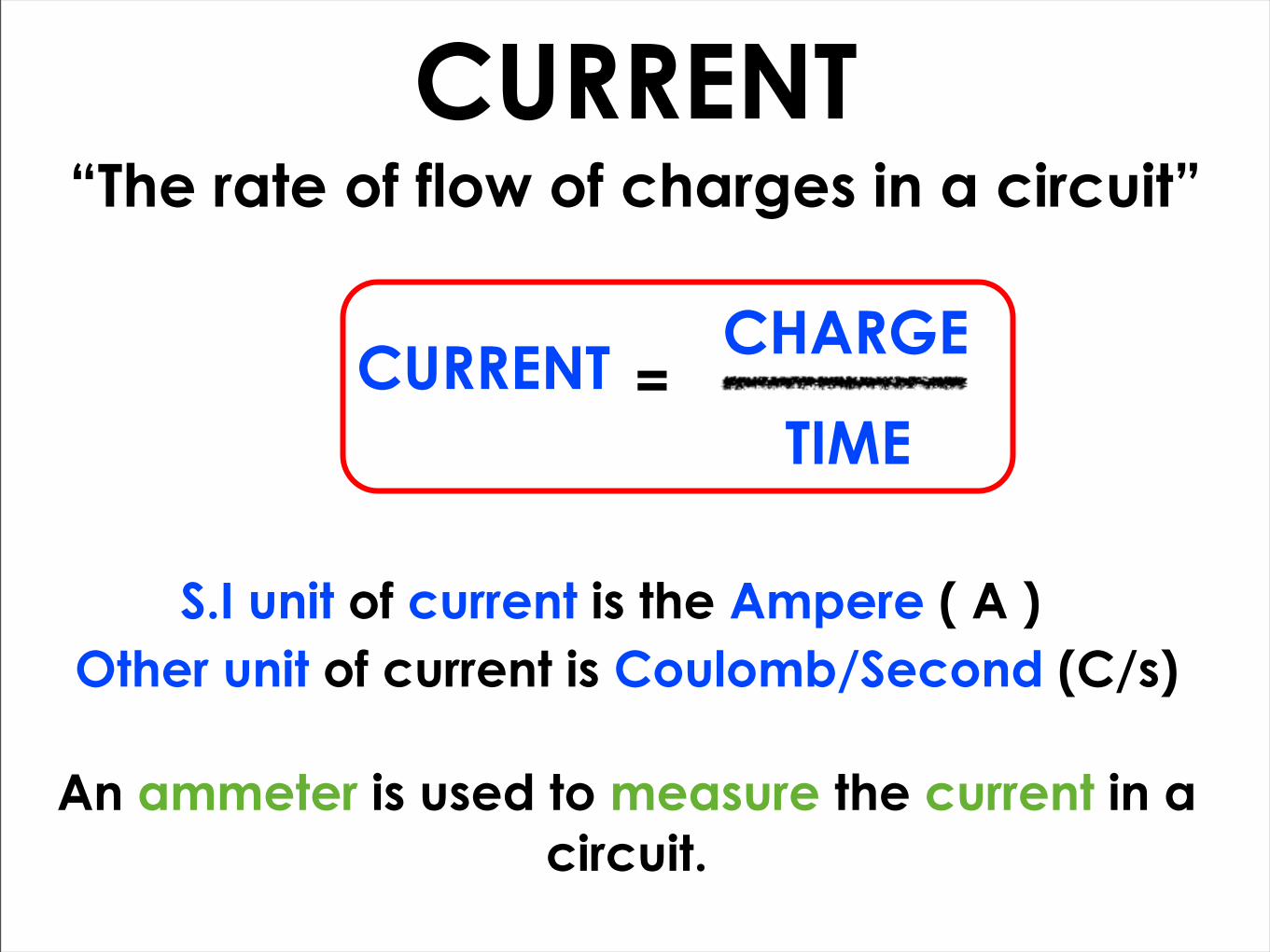
CURRENT“The rate of flow of charges in a circuit”
CURRENT CHARGE
TIME=
S.I unit of current is the Ampere ( A )Other unit of current is Coulomb/Second (C/s)
An ammeter is used to measure the current in a circuit.

CURRENT IN SERIES CIRCUIT
A
A A
A1
2 3
4
Current is the same everywhere in a series circuit.
I1 I2 I3 I4= = =

CURRENT IN PARALLEL CIRCUIT
A1
A2
A3
A4
A5
= I5I2 I3 I4= +I1 +
Current in the main branch is the sum of
current in each branch.

CURRENT IN PARALLEL CIRCUIT
A1
A2
A3
A4
A5
Branch with the highest resistance will
have the smallest current.
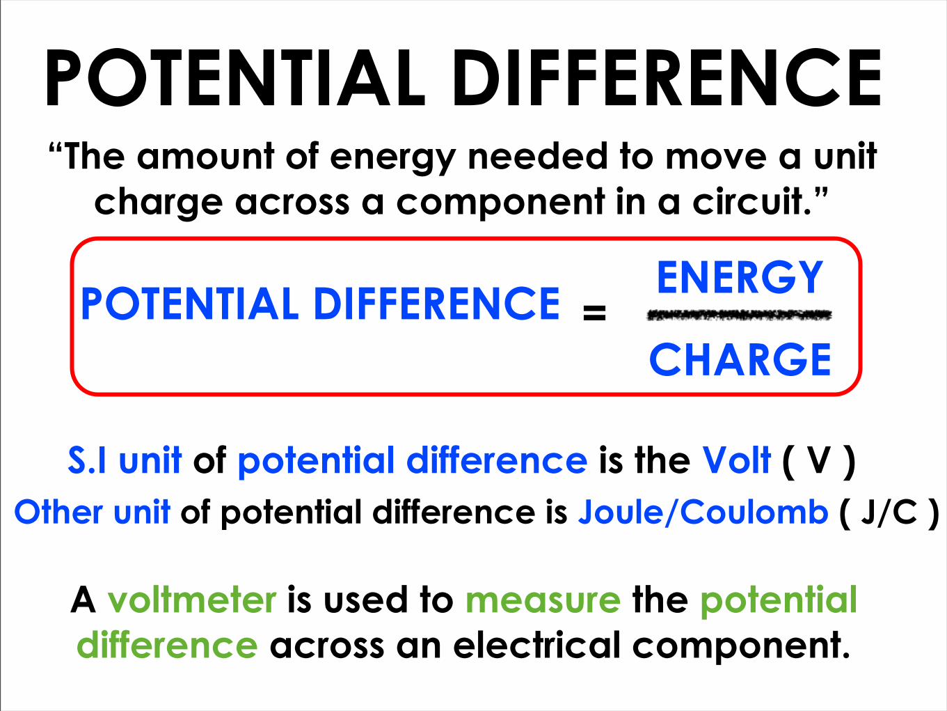
POTENTIAL DIFFERENCE“The amount of energy needed to move a unit
charge across a component in a circuit.”
POTENTIAL DIFFERENCE ENERGY
CHARGE=
S.I unit of potential difference is the Volt ( V )Other unit of potential difference is Joule/Coulomb ( J/C )
A voltmeter is used to measure the potential difference across an electrical component.

POTENTIAL DIFFERENCE IN SERIES CIRCUIT
The sum of the potential difference (pd) across each of the components of the circuit is equal to the potential
difference across the cell.
V1 V2 V3 V4= + +
V3 V4V2
V1
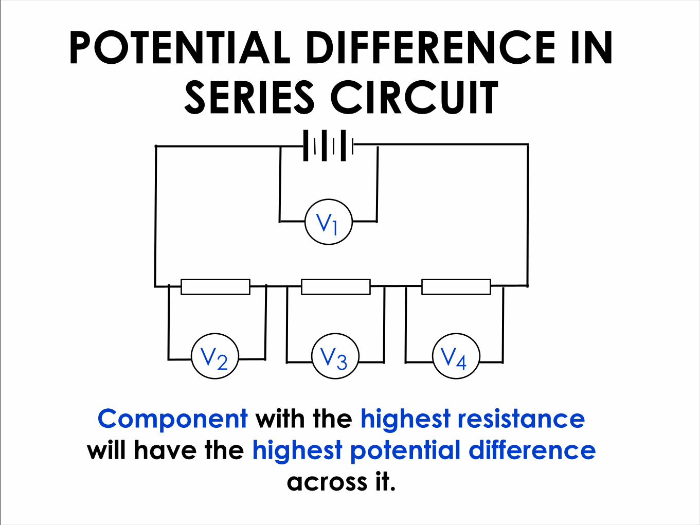
POTENTIAL DIFFERENCE IN SERIES CIRCUIT
Component with the highest resistance will have the highest potential difference
across it.
V3 V4V2
V1

POTENTIAL DIFFERENCE IN PARALLEL CIRCUIT
In a parallel circuit, the potential difference (pd) across all the branches are the same.
V1 V2 V3 V4= = =
V3 V4V2V1

RESISTANCE“The measure of the degree to which an electrical
component opposes the flow of an electric current.”
High Resistance, Low Current,
High Potential Difference
Low Resistance, High Current,
Low Potential Difference
An electrical conductor that has:
through it.
RESISTANCE POTENTIAL DIFFERENCE
CURRENT=
S.I unit of resistance is the Ohm ( Ω )

FUNCTION OF RESISTORS
Resistors in a circuit
Main function is to control
the amount of current flowing
in a circuit.

RESISTORS IN SERIES
R RR1 2 3
The total resistance is the sum of each resistance in the series circuit.
R TOTAL R1 R2 R3= + +
MORE resistors in series, HIGHER total resistance.

RESISTORS IN PARALLEL
R1
R2
R3
MORE resistors in parallel, SMALLER total resistance.
R TOTAL R1 R2 R3= + +
1 1 1 1

EXAMPLE EXERCISE 15129/12/M/J/12 Q36
A resistor in a circuit has a value of resistance of 3.0 Ω.
In 20 s, a charge of 10 C passes through the resistor.
What is the potential difference across the resistor?
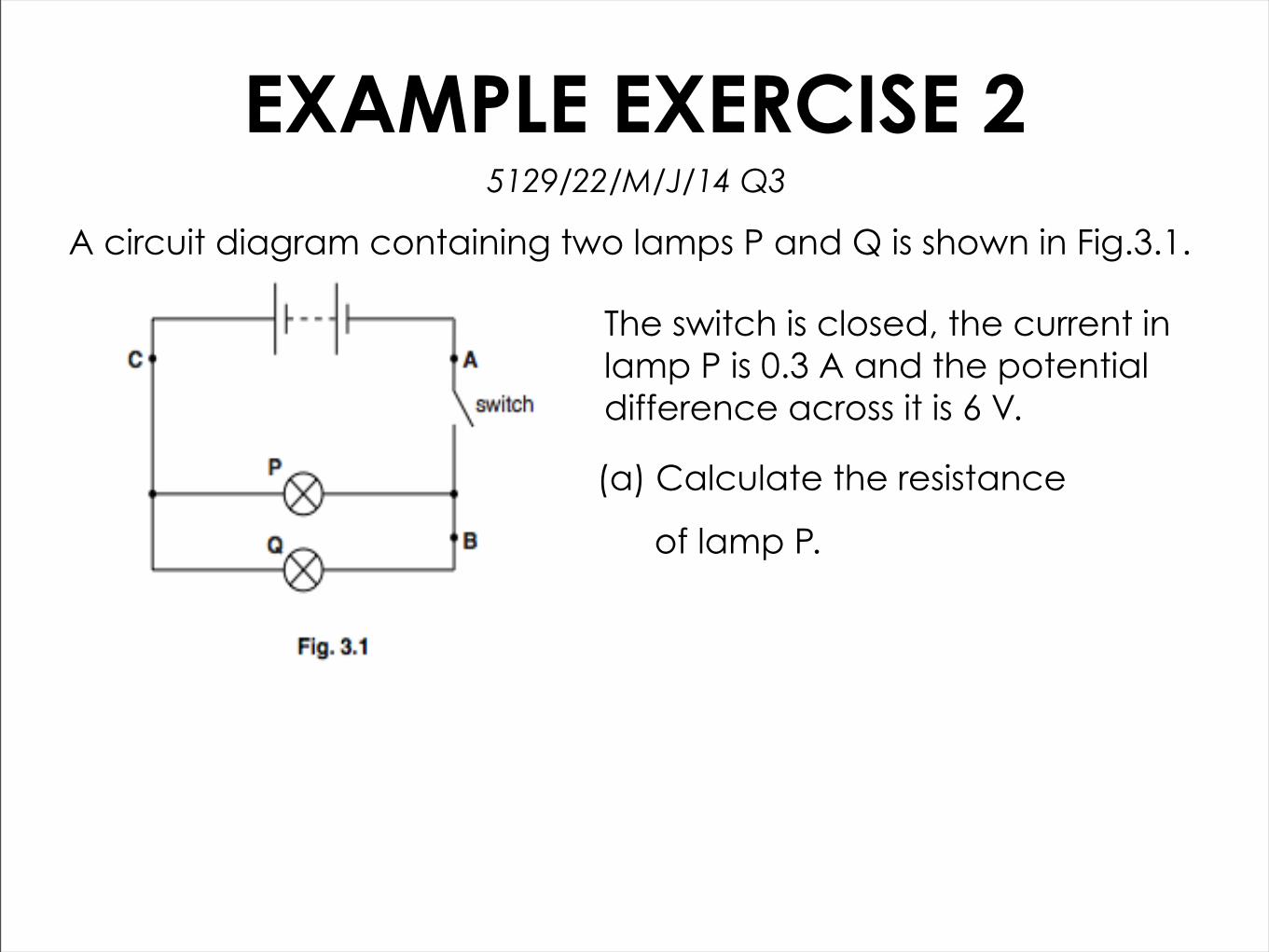
EXAMPLE EXERCISE 25129/22/M/J/14 Q3
A circuit diagram containing two lamps P and Q is shown in Fig.3.1.
(a) Calculate the resistance
of lamp P.
The switch is closed, the current in lamp P is 0.3 A and the potential difference across it is 6 V.

EXAMPLE EXERCISE 25129/22/M/J/14 Q3
A circuit diagram containing two lamps P and Q is shown in Fig.3.1.
(b) The current in lamp Q is 0.2 A.
Determine the current in the circuit at:
(i) Point A
(ii) Point B
(iii) Point C
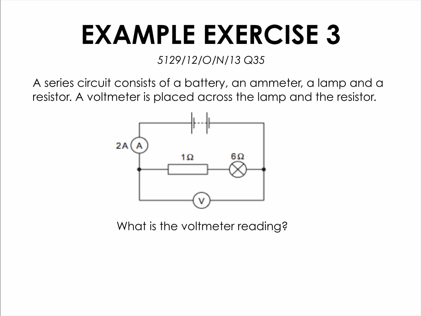
EXAMPLE EXERCISE 35129/12/O/N/13 Q35
A series circuit consists of a battery, an ammeter, a lamp and a resistor. A voltmeter is placed across the lamp and the resistor.
What is the voltmeter reading?
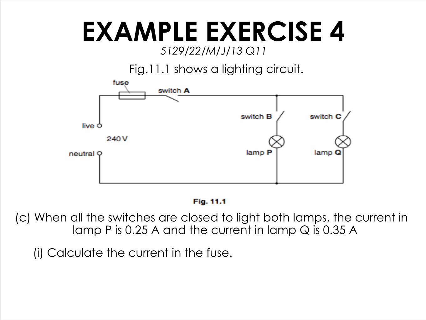
EXAMPLE EXERCISE 4Fig.11.1 shows a lighting circuit.
5129/22/M/J/13 Q11
(c) When all the switches are closed to light both lamps, the current in lamp P is 0.25 A and the current in lamp Q is 0.35 A
(i) Calculate the current in the fuse.

EXAMPLE EXERCISE 55129/12/M/J/13 Q37
A circuit consists of a battery and four resistors. The current in three of the resistors is shown.
What is the current in X?

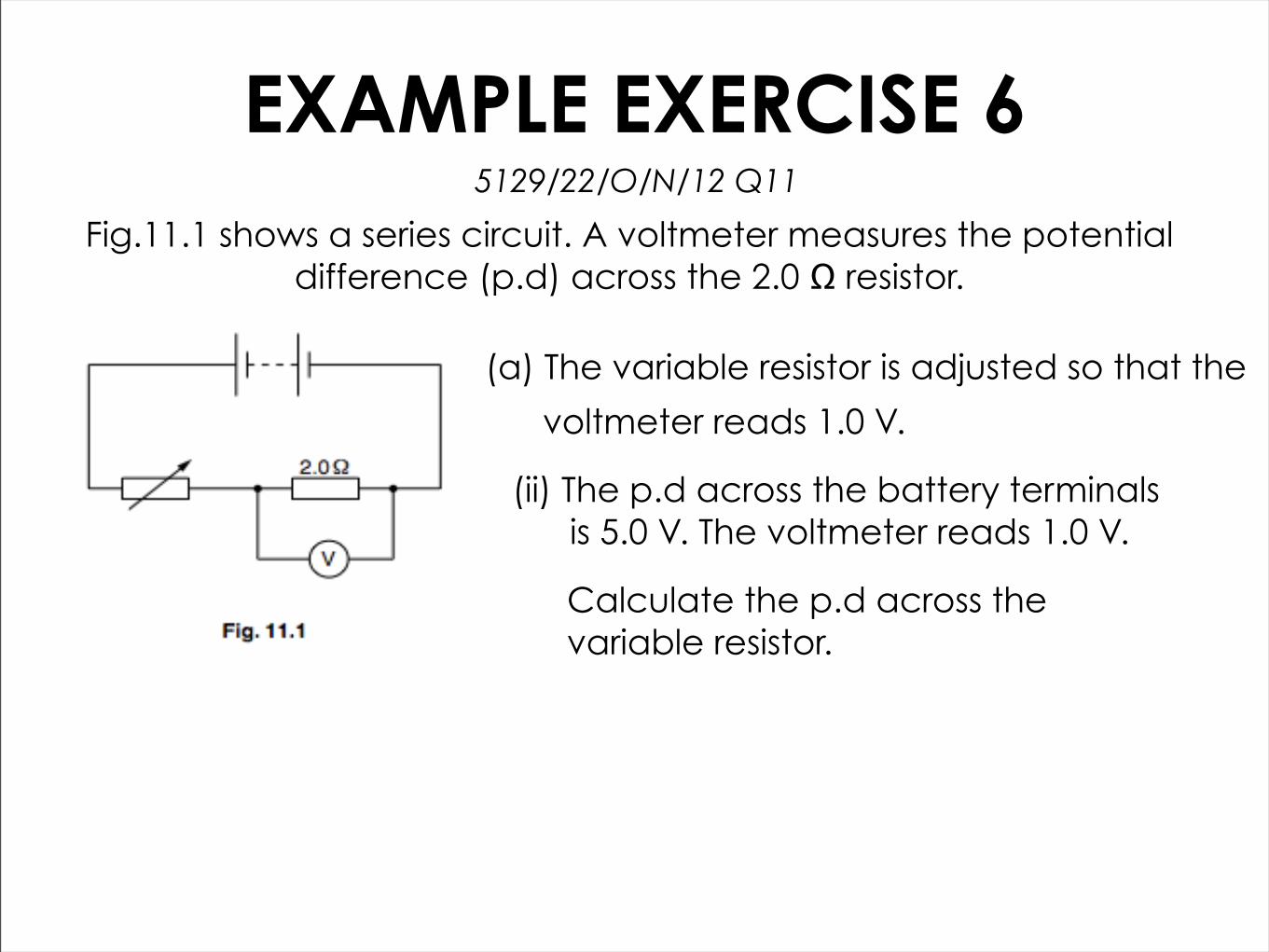
EXAMPLE EXERCISE 65129/22/O/N/12 Q11
Fig.11.1 shows a series circuit. A voltmeter measures the potential difference (p.d) across the 2.0 Ω resistor.
(a) The variable resistor is adjusted so that the
voltmeter reads 1.0 V.
(i) Calculate the current in the 2.0 Ω resistor.
EXAMPLE EXERCISE 65129/22/O/N/12 Q11
Fig.11.1 shows a series circuit. A voltmeter measures the potential difference (p.d) across the 2.0 Ω resistor.
(a) The variable resistor is adjusted so that the
voltmeter reads 1.0 V.
(ii) The p.d across the battery terminals is 5.0 V. The voltmeter reads 1.0 V.
Calculate the p.d across the variable resistor.

EXAMPLE EXERCISE 65129/22/O/N/12 Q11
Fig.11.1 shows a series circuit. A voltmeter measures the potential difference (p.d) across the 2.0 Ω resistor.
(b) The resistance of the variable resistor is increased.
(i) the current in the variable resistor
(ii) the p.d across the 2.0 Ω resistor
State what happens, if anything, to:
PRACTISE QUESTIONS
5129/12/O/N/14 Q37
Complete the following questions in pairs.
5129/12/O/N/14 Q38
5129/22/O/N/14 Q14
Remember to raise your hands if you needed help with the question.