16. crankcase/transmission/crankshaft/balancer (after...
TRANSCRIPT

16. CRANKCASE/TRANSMISSION/CRANKSHAFT/BALANCER (After '05)
SYSTEM COMPONENTS 16-2 TRANSMISSION 16-13
SERVICE INFORMATION 16-3 CRANKSHAFT 16-17
TROUBLESHOOTING 16-6 CRANKCASE BEARING 16-19
BALANCER GEAR/BALANCER •••• 16-7 CRANKCASE ASSEMBLY 16-25
CRANKCASE SEPARATION 16-11
16-1

CRANKCASE/TRANSMISSION/CRANKSHAFT/BALANCER (After '05)
SYSTEM COMPONENTS
108 N-m (11.0 kgfm, 80 Ibfft)
54 N-m (5.5 kgf m,40 Ibfft)
16N-m(1.6kgf-m, 12 Ibfft)
12N-m(1.2kgf-m,9 Ibfft)
10N-m(1.0kgf
16N-m(1.6kgf-m, 12
12 N-m (1.2 kgfm, 9 Ibf-ft)
12 N-m (1.2 kgf-m, 9 Ibf-ft)
(1.2 kgfm, 9 Ibf-ft)
12 N-m (1.2 kgfm, 9 Ibfft)
12 N-m (1.2 kgfm, 9 Ibfft)
12 N-m (1.2 kgfm,9 Ibfft)
16-2

CRANKCASE/TRANSMtSSION/CRANKSHAFT/BALANCER (After '05)
SERVICE INFORMATIONGENERAL• The crankcase halves must be separated to service the transmission, crankshaft and oil pump. To service these parts,
the engine must be removed from the frame (page 10-5).• Be careful not to damage the crankcase mating surfaces when servicing.
SPECIFICATIONSUnit: mm (in)
ITEMShift fork,shaft
Transmission
Crankshaft
Fork I.D.
Shaft O.D.
LeftRightCenterLeft/rightCenter
Fork claw thicknessGear I.D;
Gear bushing O.D.
Gear bushing I.D.
Mainshaft O.D.Countershaft O.D.
Runout
M4M5C1C2C3M4, M5C1C2C3M5C1C2C3atM5atCiatC2atC3LeftRight
Big end side clearanceBig end radial clearance
STANDARD12.035 - 12.056 (0.4738 - 0.4746)12.003 - 12.024 (0.4726 - 0.4734)11.003 - 11.024 (0.4332 - 0.4340)11.966 - 11.984 (0.4711 - 0.4718)10.969 - 10.980 (0.4319 - 0.4323)4.93-5.00(0.194-0.197)28.007 - 28.028 (1.1026 - 1.1035)28.020 - 28.033 (1.1031 - 1.1037)22.020 - 22.041 (0.8669 - 0.8678)30.020-30.041 (1.1819-1.1827)28.020 - 28.041 (1.1031 - 1.1040)27.959 - 27.980 (1.1007 - 1.1016)21.959 - 21.980 (0.8645 - 0.8654)29.959 - 29.980 (1.1795 - 1.1803)27.959 - 27.980 (1.1007 - 1.1016)25.020-25.041 (0.9850-0.9859)19.020-19.041 (0.7488-0.7496)27.020 - 27.041 (1.0638 - 1.0646)25.020 - 25.041 (0.9850 - 0.9859)24.967 - 24.980 (0.9830 - 0.9835)18.959 - 18.980 (0.7464 - 0.7472)26.959 - 26.980 (1.0614 - 1.0622)24.959 - 24.980 (0.9826 - 0.9835)
--
0.30-0.75(0.012-0.030)0.006 - 0.018 (0.0002 - 0.0007)
SERVICE LIMIT12.07(0.475)12.04(0.474)11.04 (0.435)11.950 (0.4700)10.969 (0.4319)4.8 (0.19)28.05(1.104)28.06(1.105)22.07 (0.869)30.07(1.184)28.07 (1.105)27.94(1.100)21.94 (0.864)29.94(1.179)27.94(1.100)25.06 (0.987)19.06 (0.750)27.06(1.065)25.06 (0.987)24.95 (0.982)18.94(0.746)26.94(1.061)24.94 (0.982)0.05 (0.002)0.03(0.001)0.75 (0.030)0.05 (0.002)
TORQUE VALUE
Balancer shaft lock nut
Cam chain tensioner boltPrimary drive gear boltBearing set plate boltCrankshaft Bearing set plate boltCountershaft Bearing set plate torxscrewTransmission oil drain boltNeutral switch (hole plug bolt)Piston jet mounting bolt
54 N-m (5.5 kgf-m, 40 Ibf-ft)
12N-m(1.2kgfm, 9 Ibfft)108 N-m (11.0 kgfm, 80 Ibf-ft)12 N-m (1.2 kgfm, 9 Ibf-ft)16 N-m (1.6 kgf-m, 12 Ibf-ft)12 N-m (1.2 kgf-m, 9 Ibf-ft)
22 N-m (2.2 kgf-m, 16 Ibf-ft)12 N-m (1.2 kgf-m, 9 Ibf-ft)10 N-m (1.0 kgf-m, 7 Ibf-ft)
Apply oil to the threads and seating surface.Replace with a new one and stake.Apply locking agent to the threads.Apply oil to the threads and seating surface.Apply locking agent to the threads.Apply locking agent to the threads.Apply locking agent to the threads.
Apply oil to the threads and seating surface.
Apply locking agent to the threads.
16-3

CRANKCASE/TRANSMISSION/CRANKSHAFT/BALANCER (After '05)
TOOLS
Bearing remover handle07936-3710100
Bearing remover, 17 mm07936-3710300
Bearing remover, 20 mm07936-3710600
Remover weight07741-0010201
Driver07749-0010000
Attachment, 32 x 35 mm07746-0010100
or 07936-3710200 or 07936-371020A(U.S.A. only)
Attachment, 37 x 40 mm07746-0010200
Attachment, 42 x 47 mm07746-0010300
Attachment, 52 x 55 mm07746-0010400
Attachment, 62 x 68 mm07746-0010500
Attachment, 72 x 75 mm07746-0010600
Pilot, 17 mm07746-0040400
16-4

CRANKCASE/TRANSMISSION/CRANKSHAFT/BALANCER (After '05)
Pilot, 20 mm07746-0040500
Pilot, 25 mm07746-0040600
Pilot, 30 mm07746-0040700
Lock nut wrench, 20 x 24 mm07716-0020100
w
Extension bar07716-0020500
or commercially availableequivalent
Gear holder, M2.507724-0010100
or 07724-001A100 (U.S.A. only)
Gear holder, M1.507724-0010200
or 07724-001A200 (U.S.A. only)
16-5

CRANKCASE/TRANSMISSION/CRANKSHAFT/BALANCER (After '05)
TROUBLESHOOTINGExcessive engine noise• Worn connecting rod big end bearing• Worn crankshaft main journal bearing• Worn balancer bearing• Improper balancer installation• Worn transmission gears• Worn transmission bearings
Transmission jumps out of gear• Worn gear dogs or dog holes• Worn shift drum guide groove• Worn shift fork guide pin• Worn gear shifter groove• Worn shift fork• Bent shift fork shaft
Hard to shift• Incorrect clutch adjustment• Bent shift fork• Bent shift fork shaft• Bent shift fork claw• Damaged shift drum guide grooves• Damaged shift fork guide pin
Engine vibration• Excessive crankshaft runout• Improper balancer timing
16-6

CRANKCASE/TRANSMISSION/CRANKSHAFT/BALANCER (After '05)
BALANCER GEAR/BALANCERREMOVALRemove the following:
- right crankcase cover (page 14-5)- flywheel (page 21-12)- clutch assembly (page 14-6)
Temporarily install the clutch outer guide, needlebearing and clutch outer onto the mainshaft.Install the special tool between the primary driveand driven gears as shown, and loosen the primarydrive gear bolt.
TOOL:Gear holder, M2.5 07724-0010100 or
07724-001A100(U.S.A. only)
GEAR HOLDER•1BOLT/WASHER
Remove the clutch outer, needle bearing and clutchouter guide.Remove the primary drive gear bolt, washer andgear.
TRX450ER only: Remove the starter clutch assembly.
Install the special tool between the balancer driveand driven gears as shown, and loosen the balancershaft lock nut using the special tool.
TOOLS:Gear holder, M1.5
Lock nut wrench, 20 x 24 mmExtension bar
07724-0010200 or07724-001A200(U.S.A. only)07716-002010007716-0020500 orcommerciallyavailableequivalent
PRIMARY DRIVE GEAR
Remove the lock nut and washer.
STARTER CLUTCH ASSEMBLY
16-7

CRANKCASE/TRANSMISSION/CRANKSHAFT/BALANCER (After '05)
Remove the balancer drive and driven gears.
Position the balancer weight as shown and removethe balancer shaft.
INSPECTIONCheck the balancer shaft for wear, damage orscratches.
INSTALLATIONApply molybdenum oil solution to the balancershaft ball bearing and needle bearing.Apply grease to the balancer shaft oil seal lip.Position the balancer weight as shown, install thebalancer shaft into the crankcase.
16-8
CRANKCASE/TRANSMISSION/CRANKSHAFT/BALANCER (After '05)
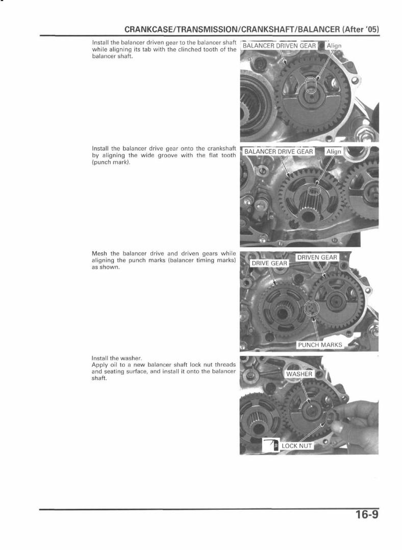
Install the balancer driven gear to the balancer shaft T . , 4 N r F R
while aligning its tab with the clinched tooth of the B A L A I N I ^ t h l
balancer shaft.
Install the balancer drive gear onto the crankshaftby aligning the wide groove with the flat tooth(punch mark).
Mesh the balancer drive and driven gears whilealigning the punch marks (balancer timing marks)as shown.
Install the washer.Apply oil to a new balancer shaft lock nut threadsand seating surface, and install it onto the balancershaft.
16-9
CRANKCASE/TRANSMISSION/CRANKSHAFT/BALANCER (After '05)
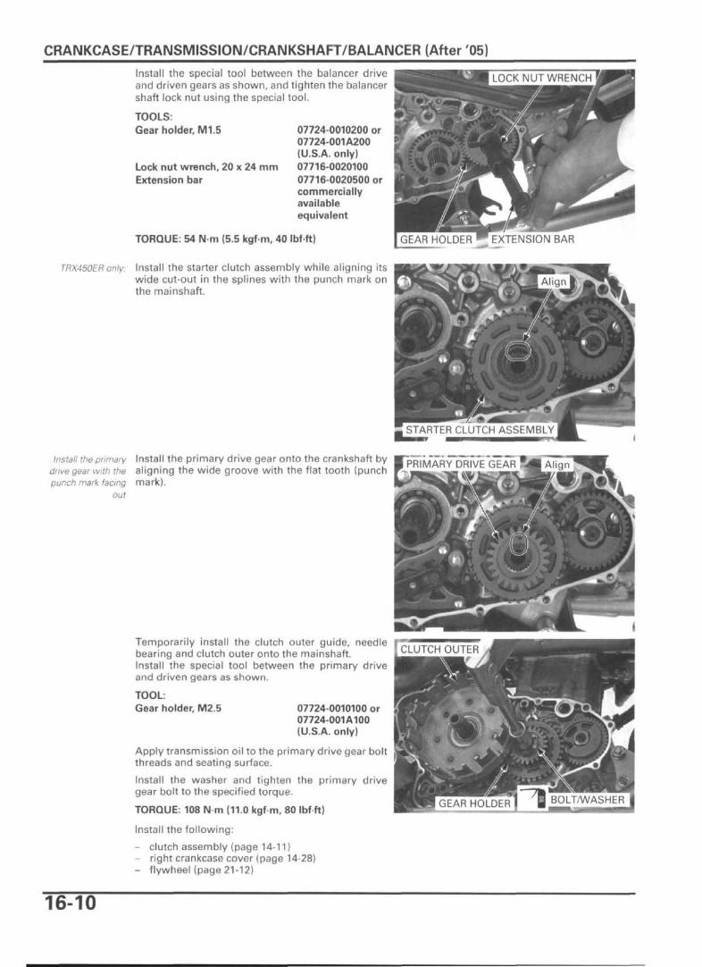
Install the special tool between the balancer driveand driven gears as shown, and tighten the balancershaft lock nut using the special tool.
TOOLS.Gear holder, M1.5
Lock nut wrench, 20 x 24 mmExtension bar
07724-0010200 or07724-001A200(U.S.A. only)07716-002010007716-0020500 orcommerciallyavailableequivalent
TORQUE: 54 N-m (5.5 kgf-m, 40 Ibfft)
TRX450ER only: Install the starter clutch assembly while aligning itswide cut-out in the splines with the punch mark onthe mainshaft.
Install the primarydrive gear with thepunch mark facing
out
Install the primary drive gear onto the crankshaft byaligning the wide groove with the flat tooth (punchmark).
Temporarily install the clutch outer guide, needlebearing and clutch outer onto the mainshaft.Install the special tool between the primary driveand driven gears as shown.
TOOL:Gear holder, M2.5 07724-0010100 or
07724-001A100(U.S.A. only)
Apply transmission oil to the primary drive gear boltthreads and seating surface.
Install the washer and tighten the primary drivegear bolt to the specified torque.
TORQUE: 108 N m (11.0 kgf m, 80 Ibf ft)
Install the following:
- clutch assembly (page 14-11)- right crankcase cover (page 14-28)- flywheel (page 21-12)
STARTER CLUTCH ASSEMBLY
16-10
CRANKCASE/TRANSMISSION/CRANKSHAFT/BALANCER (After '05)
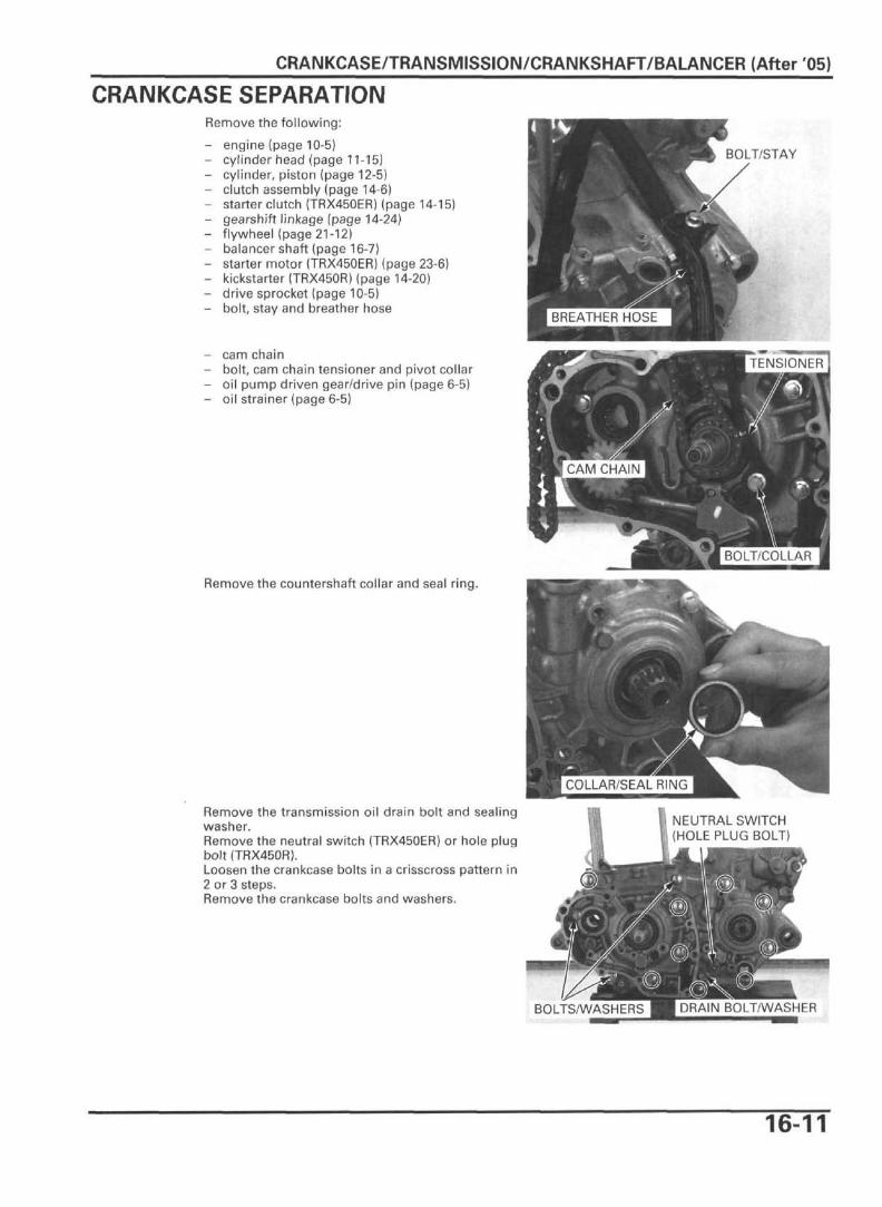
CRANKCASE SEPARATIONRemove the following:
- engine (page 10-5)- cylinder head (page 11-15)- cylinder, piston (page 12-5)- clutch assembly (page 14-6)- starter clutch (TRX450ER) (page 14-15)- gearshift linkage (page 14-24)- flywheel (page 21-12)- balancer shaft (page 16-7)- starter motor (TRX450ER) (page 23-6)- kickstarter (TRX450R) (page 14-20)- drive sprocket (page 10-5)- bolt, stay and breather hose
cam chainbolt, cam chain tensioner and pivot collaroil pump driven gear/drive pin (page 6-5)oil strainer (page 6-5)
BOLT/STAY
Remove the countershaft collar and seal ring.
Remove the transmission oil drain bolt and sealingwasher.Remove the neutral switch (TRX450ER) or hole plugbolt (TRX450R).Loosen the crankcase bolts in a crisscross pattern in2 or 3 steps.Remove the crankcase bolts and washers.
NEUTRAL SWITCH(HOLE PLUG BOLT)
BOLTS/WASHERS
16-11

CRANKCASE/TRANSMISSION/CRANKSHAFT/BALANCER (After f05)
Place the left crankcase down, separate the rightcrankcase from the left crankcase. RIGHT CRANKCASE
Remove the dowel pins and gasket.
Remove the oil pump shaft, inner and outer rotorsfrom the left crankcase if necessary.
Remove the reed valve from the right crankcase.
DOWEL PINS
GASKET
OIL PUMP SHAFT
16-12
CRANKCASE/TRANSMISSION/CRANKSHAFT/BALANCER (After '05)
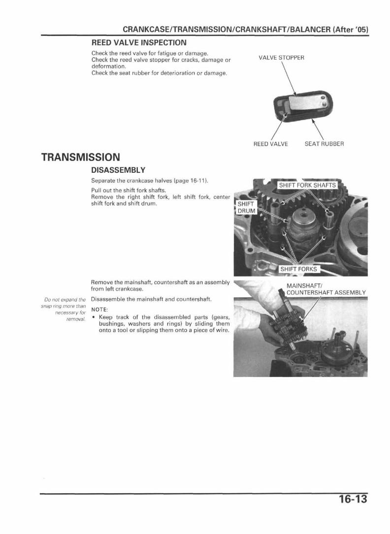
REED VALVE INSPECTIONCheck the reed valve for fatigue or damage.Check the reed valve stopper for cracks, damage ordeformation.Check the seat rubber for deterioration or damage.
VALVE STOPPER
REED VALVE SEAT RUBBER
TRANSMISSIONDISASSEMBLYSeparate the crankcase halves (page 16-11).
Pull out the shift fork shafts.Remove the right shift fork, left shift fork, centershift fork and shift drum.
Do not expand thesnap ring more than
necessary forremoval.
Remove the mainshaft, countershaft as an assemblyfrom left crankcase.
Disassemble the mainshaft and countershaft.
NOTE:• Keep track of the disassembled parts (gears,
bushings, washers and rings) by sliding themonto a tool or slipping them onto a piece of wire.
MAINSHAFT/COUNTERSHAFT ASSEMBLY
16-13

CRANKCASE/TRANSMISSION/CRANKSHAFT/BALANCER (After '05)
INSPECTIONCheck the gear shifter groove, dogs, dog holes andteeth for abnormal wear or damage.
Measure the I.D. of each gear.
SERVICE LIMITS: M4: 28.05 mm (1.104 in)M5: 28.06 mm (1.105 in)C1: 22.07 mm (0.869 in)C2: 30.07 mm (1.184 in)C3: 28.07 mm (1.105 in)
Check the bushings for abnormal wear or damage.Measure the O.D. of each bushing.
SERVICE LIMITS: M4, M5: 27.94 mm (1.100 in)C1: 21.94 mm (0.864 in)C2: 29.94 mm (1.179 in)C3: 27.94 mm (1.100 in)
Measure the I.D. of each bushing.
SERVICE LIMITS: M5: 25.06 mm (0.987 in)C1:19.06 mm (0.750 in)C2: 27.06 mm (1.065 in)C3: 25.06 mm (0.987 in)
Check the spline grooves and sliding surfaces of themainshaft and countershaft for abnormal wear ordamage.Measure the O.D. of the mainshaft and counter-shaft.
SERVICE LIMITS: at M5: 24.95 mm (0.982 in)at C1: 18.94 mm (0.746 in)at C2: 26.94 mm (1.061 in)at C3: 24.94 mm (0.982 in)
Inspect the shift drum journals for scoring,scratches or evidence of insufficient lubrication.
Check the shift drum guide grooves for abnormalwear or damage.
SHIFT DRUM
16-14

CRANKCASE/TRANSMISSION/CRANKSHAFT/BALANCER (After '05)
Check the shift fork shafts for abnormal wear ordamage.
Measure each shift fork shaft O.D.
SERVICE LIMITS:Left and right: 11.950 mm (0.4700 in)Center: 10.969 mm (0.4319 in)
Check the shift forks for abnormal wear or damage.
Measure the I.D. of each shift fork.
SERVICE LIMITS:Left: 12.07 mm (0.475 in)Right: 12.04 mm (0.474 in)Center: 11.04 mm (0.435 in)
Measure claw thickness of each shift fork.
SERVICE LIMIT: 4.8 mm (0.19 in)
ASSEMBLYMAINSHAFT
M5 BUSHING
M1 GEAR(13T)
MAINSHAFT
THRUST WASHER
SPLINE WASHER
M4 BUSHING
M5 GEAR (27T)
SPLINE WASHER
M3GEAR(16T)SPLINE WASHER
M2 GEAR (14T)
LOCK WASHER
THRUST WASHER
16-15

CRANKCASE/TRANSMISSION/CRANKSHAFT/BALANCER (After '05)
COUNTERSHAFT
C1 GEAR (29T) THRUST WASHER
THRUST WASHER
C5 GEAR (26T)
SNAP RING
SPLINE WASHER
C3 GEAR (23T)
C3 BUSHINGTHRUST WASHER
C2 BUSHING
THRUST WASHER
THRUST WASHER
C2 GEAR (25T)
Apply molybdenum oil solution to the sliding sur-faces of the transmission gears.
Assemble the mainshaft and countershaft.
NOTE:• Always install the washer and snap ring with the
chamfered (rolled) edge facing away from thethrust load.
• Do not reuse worn snap ring which could easilyspin in the groove.
• Install the snap ring so that its end gap alignswith the groove in the splines.
• Make sure that the snap ring is fully seated in theshaft groove after installing it.
Install the mainshaft and countershaft as an assem-bly into the left crankcase.
: Gear sliding surfaces MAINSHAFT
COUNTERSHAFT
MAINSHAFT/I COUNTERSHAFT ASSEMBLY
16-16

CRANKCASE/TRANSMISSION/CRANKSHAFT/BALANCER (After '05)
Make sure the shift fork identification marks.The left shift fork has an "EYL" mark, the center shiftfork has a "CP1" mark and the right shift fork has an"RP1" mark.
"EYL" "CP1" "RP1"
Face the shift fork marks as follows:- Left shift fork mark to the left crankcase- Center and right shift fork marks to the
crankcaseright
Apply molybdenum oil solution to the claws andguide pins of the left, center and right shift forks.Install the shift forks to the grooves in the slidinggears.
Apply oil to the shift drum guide grooves and installit into the left crankcase.Install the shift fork guide pins into the shift drumguide grooves.
Apply molybdenum oil solution to the shift forkshafts and install them through the shift forks andinto the left crankcase.
Assemble the crankcase halves (page 16-25).
CRANKSHAFTREMOVALSeparate the crankcase halves (page 16-11).Remove the transmission (page 16-13).
Remove the crankshaft from the left crankcase.
CRANKSHAFT
INSPECTIONSet the crankshaft on a stand or V-blocks and mea-sure the runout using a dial indicator.
SERVICE LIMITS: L: 0.05 mm (0.002 in)R: 0.03 mm (0.001 in)
4.0 mm (0.16 in) 6.0 mm (0.24 in)
16-17

CRANKCASE/TRANSMISSION/CRANKSHAFT/BALANCER (After '05)
Measure the connecting rod big end side clearance.
SERVICE LIMIT: 0.75 mm (0.030 in)FEELER GAUGE
Measure the connecting rod big end radial clear-ance.
SERVICE LIMIT: 0.05 mm (0.002 in)
INSTALLATIONCoat the oil seal contacting surface of the crankshaftwith oil.Apply grease to a new crankshaft oil seal lip andinstall it into the left crankcase.Install the crankshaft into the left crankcase.
Install the transmission (page 16-15).Assemble the crankcase halves (page 16-25).
CRANKSHAFT LEFT CRANKCASE
16-18

CRANKCASE/TRANSMISSION/CRANKSHAFT/BALANCER (After '05)
LEFT CRANKCASE BEARINGREPLACEMENTRemove the crankshaft oil seal.
Remove the set plate bolts, washers and set platesfrom the left crankcase.
Drive the crankshaft bearing out of the left crank-case.
Remove the countershaft and balancer shaft oils e a l s - - , COUNTERSHAFT
Remove the torx screws and countershaft bearingset plates.
Drive the countershaft bearing out of the left crank-case.
Remove the snap ring from left crankcase.
CRANKSHAFTBEARING
BOLTS/WASHERS
BALANCER SHAFT
* m TORX SCREWS/SET PLATES
COUNTERSHAFTBEARRING
BALANCER SHAFT BEARING
16-20

CRANKCASE/TRANSMISSION/CRANKSHAFT/BALANCER (After '05)
CRANKCASE BEARINGCRANKCASE BEARING/OIL SEAL LOCATION
OIL SEAL (39 x 60 x 7.5)
RIGHT CRANKCASE:
RIGHT BALANCER SHAFTBEARING (17x42x13)
I I M
\RIGHT CRANKSHAFTBEARING (30x76x19)
IQI IDT
RIGHT COUNTERSHAFTBEARING (17x42x12)
RIGHT MAINSHAFTBEARING (25x56x15)
LEFT CRANKCASE:
LEFT BALANCER SHAFTBEARING (20x32x14)
LEFT CRANKSHAFTROLLER BEARING LEFT COUNTERSHAFT
BEARING (24x56x22.1)
OIL SEAL (20x33x7.5) OIL SEAL (38x52x7) LEFT MAINSHAFTBEARING (6203 SPL) OIL SEAL (31 x40x7)
INSPECTIONRemove the crankshaft (page 16-17).
Turn the inner race of each crankcase bearing withyour finger. The bearing should turn smoothly andquietly.Also check that the bearing outer race fits tightly inthe crankcase.
Replace any bearing if the inner race does not turnsmoothly, quietly or if the outer race fits loosely inthe crankcase.
16-19
CRANKCASE/TRANSMISSION/CRANKSHAFT/BALANCER (After '05)
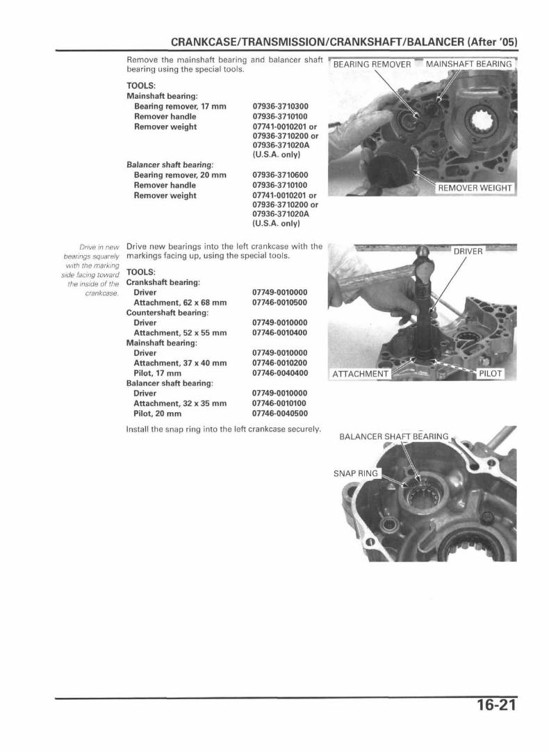
Remove the mainshaft bearing and balancer shaft - BEARING REMOVER ~ MAINSHAFT BEARING "bearing using the special tools.
TOOLS:Mainshaft bearing:
Bearing remover, 17 mmRemover handleRemover weight
Balancer shaft bearing:Bearing remover, 20 mmRemover handleRemover weight
07936-371030007936-371010007741-0010201 or07936-3710200 or07936-371020A(U.S.A. only)
07936-371060007936-371010007741-0010201 or07936-3710200 or07936-371020A(U.S.A. only)
IREMOVER WEIGHT IIGHT|
Drive in newbearings squarelywith the marking
side facing towardthe inside of the
crankcase.
Drive new bearings into the left crankcase with the t,markings facing up, using the special tools.
TOOLS:Crankshaft bearing:
DriverAttachment, 62 x 68 mm
Countershaft bearing:DriverAttachment, 52 x 55 mm
Mainshaft bearing:DriverAttachment, 37 x 40 mmPilot, 17 mm
Balancer shaft bearing:DriverAttachment, 32 x 35 mmPilot, 20 mm
07749-001000007746-0010500
07749-001000007746-0010400
07749-001000007746-001020007746-0040400
07749-001000007746-001010007746-0040500
Install the snap ring into the left crankcase securely.BALANCER SHAFT BEARING
SNAP RING
16-21

CRANKCASE/TRANSMISSION/CRANKSHAFT/BALANCER (After '05)
Apply locking agent to the torx screw threads.Install the countershaft bearing set plates andtighten the torx screws to the specified torque.
TORQUE: 12 N m (1.2 kgf m, 9 Ibfft)
Apply grease to a new countershaft and balancershaft oil seal lips.Install the oil seals to the crankcase until it is flushwith the crankcase surface.
Apply a locking agent to the set plate bolt threads.Install the set plates, washers and bolts to the leftcrankcase.Tighten the set plate bolts to the specified torque.
TORQUE: 16 N-m (1.6 kgf m, 12 Ibfft)
Apply grease to a new crankshaft oil seal lip.Install the oil seal to the crankcase until it is flushwith the crankcase surface.
TORX SCREWS/SET PLATES
COUNTERSHAFTBEARRING
COUNTERSHAFTOIL SEAL
BALANCER SHAFTOIL SEAL
RIGHT CRANKCASERemove the bolts and oil guide plate from the rightcrankcase.
OIL GUIDE PLATE
16-22
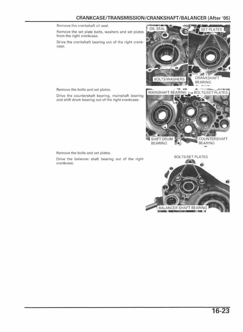
CRANKCASE/TRANSMISSION/CRANKSHAFT/BALANCER (After '05)Remove the crankshaft oil seal.
Remove the set plate bolts, washers and set platesfrom the right crankcase.
Drive the crankshaft bearing out of the right crank-case.
Remove the bolts and set plates.
Drive the countershaft bearing, mainshaft bearingand shift drum bearing out of the right crankcase.
MAINSHAFT BEARING ^ BOLTS/SET PLATES
I SHIFT DRUMBEARING
COUNTERSHAFTBEARING
Remove the bolts and set plates.
Drive the balancer shaft bearing out of the rightcrankcase.
BOLTS/SET PLATES
BALANCER SHAFT BEARING
16-23
CRANKCASE/TRANSMISSION/CRANKSHAFT/BALANCER (After 05)
Drive in newbearings squarelywith the marking
side facing towardthe inside of the
crankcase.
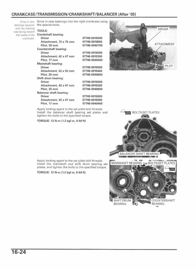
Drive in new bearings into the right crankcase usingthe special tools.
TOOLS:Crankshaft bearing:
DriverAttachment, 72 x 75 mmPilot 30 mm
Countershaft bearing:DriverAttachment, 42 x 47 mmPilot, 17 mm
Mainshaft bearing:DriverAttachment, 52 x 55 mmPilot, 25 mm
Shift drum bearing:DriverAttachment, 42 x 47 mmPilot, 25 mm
Balancer shaft bearing:DriverAttachment, 42 x 47 mmPilot, 17 mm
07749-001000007746-001060007746-0040700
07749-001000007746-001030007746-0040400
07749-001000007746-001040007746-0040600
07749-001000007746-001030007746-0040600
07749-001000007746-001030007746-0040400
Apply locking agent to the set plate bolt threads.Install the balancer shaft bearing set plates andtighten the bolts to the specified torque.
TORQUE: 12 N m (1.2 kgf m, 9 Ibf ft)
Apply locking agent to the set plate bolt threads.Install the mainshaft and shift drum bearing setplates, and tighten the bolts to the specified torque.
TORQUE: 12 N m (1.2 kgf m, 9 Ibf ft)
PILOT
BOLTS/SET PLATES
f»
I SHIFT DRUMBEARING
COUNTERSHAFTBEARING
16-24
CRANKCASE/TRANSMISSION/CRANKSHAFT/BALANCER (After '05)
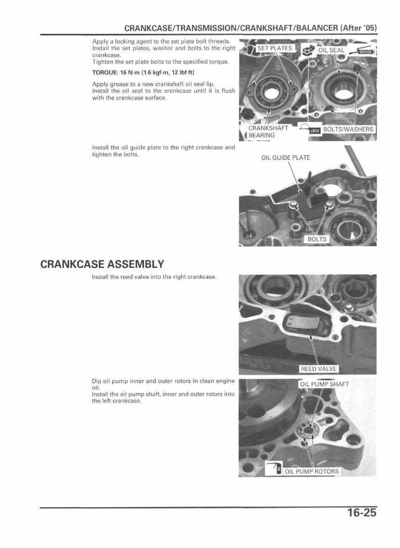
Apply a locking agent to the set plate bolt threads.Install the set plates, washer and bolts to the rightcrankcase.Tighten the set plate bolts to the specified torque.
TORQUE: 16 Nm (1.6 kgf-m, 12 Ibfft)
Apply grease to a new crankshaft oil seal lip.Install the oil seal to the crankcase until it is flushwith the crankcase surface.
Install the oil guide plate to the right crankcase andtighten the bolts.
CRANKSHAFTBEARING
CRANKCASE ASSEMBLYInstall the reed valve into the right crankcase.
Dip oil pump inner and outer rotors in clean engineoil.Install the oil pump shaft, inner and outer rotors intothe left crankcase.
16-25
CRANKCASE/TRANSMISSION/CRANKSHAFT/BALANCER (After '05)
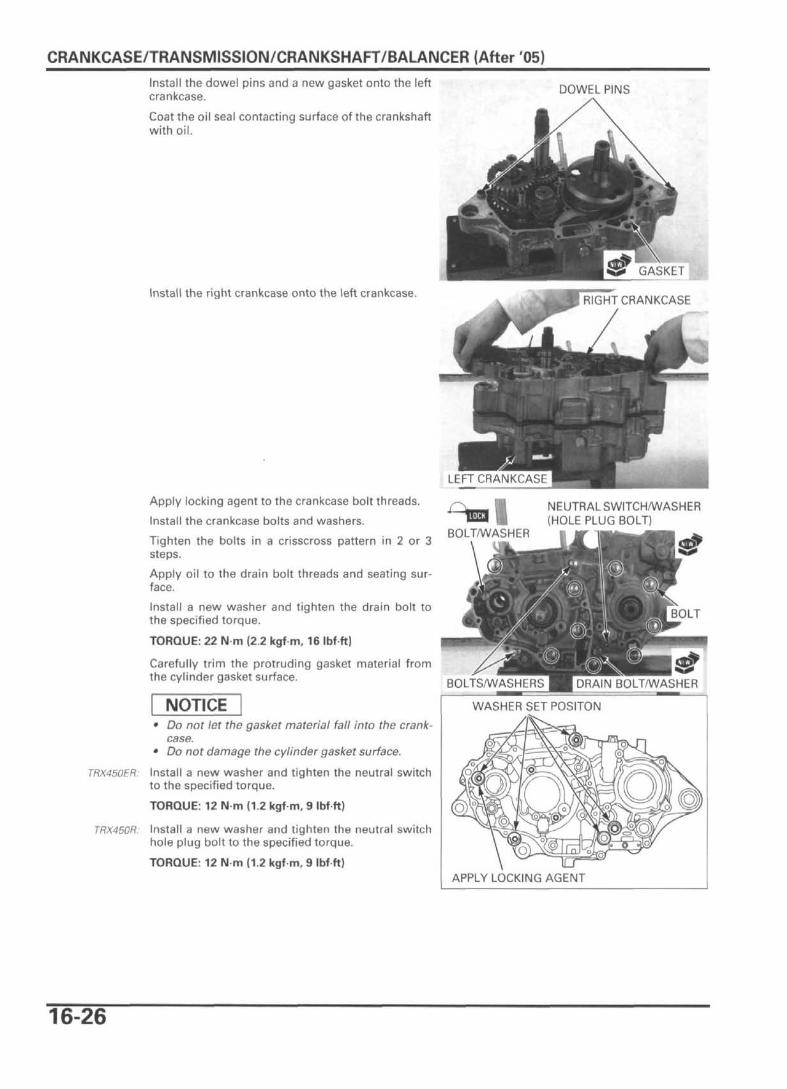
Install the dowel pins and a new gasket onto the leftcrankcase.
Coat the oil seal contacting surface of the crankshaftwith oil.
DOWEL PINS
Install the right crankcase onto the left crankcase.
GASKET
RIGHT CRANKCASE
Apply locking agent to the crankcase bolt threads.
Install the crankcase bolts and washers.
Tighten the bolts in a crisscross pattern in 2 or 3steps.
Apply oil to the drain bolt threads and seating sur-face.
Install a new washer and tighten the drain bolt tothe specified torque.
TORQUE: 22 N m (2.2 kgf m, 16 Ibfft)
Carefully trim the protruding gasket material fromthe cylinder gasket surface.
NOTICE• Do not let the gasket material fall into the crank-
case.• Do not damage the cylinder gasket surface.
TRX450ER: Install a new washer and tighten the neutral switchto the specified torque.
TORQUE: 12 N m (1.2 kgf m, 9 Ibfft)
TRX450R. Install a new washer and tighten the neutral switchhole plug bolt to the specified torque.
TORQUE: 12 N-m (1.2 kgf m, 9 Ibfft)
'iLUU IBOLT/WASHER
NEUTRAL SWITCH/WASHER(HOLE PLUG BOLT)
BOLTS/WASHERS H DRAIN BOLT/WASHER
WASHER SET POSITON
APPLY LOCKING AGENT
16-26

CRANKCASE/TRANSMISSION/CRANKSHAFT/BALANCER (After '05)
Coat the countershaft seal ring with grease andinstall the countershaft collar onto the countershaft.
Apply locking agent to the cam chain tensioner boltthreads.Install the cam chain tensioner and collar, andtighten the bolt.
TORQUE: 12 N-m (1.2 kgf-m, 9 Ibf-ft)
Install the cam chain.
Install the following:
- oil strainer (page 6-6)- oil pump driven gear/drive pin (page 6-6)
breather hosesdrive sprocket (page 10-9)kickstarter (TRX450R) (page 14-23)starter motor (TRX450ER) (page 23-12)balancer shaft (page 16-8)flywheel (page 21-12)gearshift linkage (page 14-26)starter clutch (TRX450ER) (page 14-19)clutch assembly (page 14-11)cylinder, piston (page 12-10)cylinder head (page 11-24)engine (page 10-9)
16-27