150 series “apco-chem” regenerative turbine process pumps ... · pdf file150...
TRANSCRIPT

150 Series “APCO-CHEM”Regenerative Turbine Process Pumps for Low FlowHigh Pressure Applications
• Capacities To 115 GPM• Heads To 1200 Feet• Temperatures To 500° F• Meets ANSI B73.1 Std.
BULLETIN 150 / REV. F

150 Series “APCO-CHEM” Process Turbine Pump
Low Flow, High Pressure Regenerative Turbine Process Pump
Process Industry Field Proven For: ● Chemicals ● Petrochemicals ● Refinery ● Pulp and Paper ● General Industry
Services: ● Boiler Feed ● Condensate ● Chemical Transfer ● Injection
Design Features: ● Steep head capacity curves for applications that require minimal flow change. ● Ability to handle vapors up to 20% by volume. ● Steady flow—eliminates pulsation problems associated with other pump designs. ● Back pull-out design for low cost, one craft maintenance. ● Top vertical centerline discharge. ● Pump has known shut-off pressure as opposed to positive displacement designs. ● Reduced down-time for bearing and seal maintenance. ● Pump built to ANSI B73.1 dimensional standards for maximum interchangeability. ● Lower operating costs than standard centrifugal pumps at low flow conditions. ● Balanced double suction impeller design reduces axial thrust.
Shaft Arrangement – With shaft sleeve. Seal Types – Single or double, inside,balanced or unbalanced. Glands – Plain, flush, quench, vent anddrain. Seat Mounting – Flexibly mounted “O”-ring or clamped stationary seat.Flush Plans – ANSI and APIconfigurations available.
Sealing FlexibilityType 1100Single inside seal – cartridge seal
Type 88 Double seal or tandem cartridge
© John Crane Inc., Seal Pictures
Type 1BSingle inside

“APCO-CHEM” Design Features of the One and Two Stage Turbine Typ
Optional Design Features● Jacketed stuffing box for cooling or heating mechanical seal cavity.● Jacketed bearing frame provides bearing cooling for high temperature services.● Case centerline mounting for high temperature services (not available on Model 151).
Rigid shaft and shortbearing span increasemechanical seal life.
Sealing flexibility(mechanical seal orpacking).
Double suction floating impelleraxial thrust load
Model 151 and 152(Single Stage Design)
Hook type shaft sleeveallows expansion fortemperature changes.
Single row radial anddouble row thrustbearings for extended life.
Oil or greaselubrication.

Model 153 and 154Liquid End
Replaceable channelrings allow ease ofmaintenance. Balancing holes reduce
axial thrust.
Two stage designfor ultra highheads.
pe Pump
ndbalances.

Optimal Hydraulic Coverage
“APCO-CHEM” TurbinePumps Specific speed (Ns)1 can be thought of asa hydraulic index number indicating aspecific type of pump best suited for aparticular application. The HydraulicInstitute lists a range of Ns from 500through 20,000 for centrifugal pumpsstarting at a straight radial impeller andprogressing through an axial-flow design.2
But, what about Ns’s below 500? This iswhere the unique Apco-Chemregenerative turbine can best serve thosespecial pumping applications. Considerthe following pumping requirements at3500 RPM.
Now try to find a good centrifugal pumpthat would meet those pumping require-ments at a reasonable efficiency, NPSHrequirement, and operating life. Ratherdifficult!
However, look at the quality performancea regenerative turbine can give to thoserequirements. Specific speed, then, is anindex that indicates the type of pump bestsuited for the myriad pumping appli-cations in the marketplace. Ns below 500can best be handled by regenerative
Head (FT) 600 600 600 600
Flow (GPM) 10 30 60 90
NS 91 158 224 274
1500
1100
1000
500
400
300
200
900
100
90
5060
40
30
20
10
TO
TA
L D
YN
AM
IC H
EA
D-F
EE
T
30 4050
6070
8090
100 200300
400500
600700
1000
CAPACITY–GPM
APCO-CHEMTURBINEPUMPS
2000
1200
ANSICENTRIFUGAL
PUMPS
turbines that have the inherent hydrauliccapabilities of pumping low flows andhigh head requirements.
1Specific Speeds Ns = (RPM) (GPM)1/2
(FT. of Head)3/42See ANSI/HI 1.1-1.5-1994 standards page 3.
EXAMPLE: Select a pump for20 G.P.M., 320 feet TotalDynamic Head, with 3 footN.P.S.H. available. Enter curveat 320 ft. and move to right to3’ N.P.S.H. line. Read down to20.5 G.P.M. To determine theB.H.P., go back to 320 foot lineand continue to right to solidHead-Capacity curve, thendown to B.H.P. curve, then toright and read 4.7 B.H.P. Forapplication where N.P.S.H.available exceeds that as shownby dotted lines, select pumpcapacity and B.H.P. on solidlines. 11PC-115661
150 SERIES TURBINE TYPE PUMPS
EFF40
30
20
10
U.S. GPM0
SHAFTPOWER
(BHP
)
(KW)
2.9
5.97
4
8
128.95
4
HEAD
(MET
ERS)
0
361
1632
4864
8096
8 12 16 20 24 28 320
5010
015
020
025
030
0
2 3 4 5 6 7 8
HEAD
(FEE
T)
M /HR3
MAXIMUM HEAD
BHP
2' NPSH
HEAD-CAPACITY
4' NPSH
EFFICIENCY
EXAMPLE
SIZE: CT 9231750 R.P.MIMPELLER NO. 444-2195R.H. RING NO. 676-1933L.H. RING NO. 676-1926PERFORMANCE BASEDON WATER SP. GR. 1.0

Process Turbine Pump Principles of Operation
Turbine pumps derive theirname from the many bucketsmachined into the peripheryof the rotating impeller.They have long since beenrecognized for theireffectiveness in the areas oflow flow, high headapplication. The turbinepump offers higher headsthan centrifugal pumps.
Because the head capacitycurve is steep in a turbinepump, a greater degree offlexibility is available to theprocess engineer. Turbinepumps having top center linedischarge are self-ventingand have the ability tohandle vapors without vaporlock.
This characteristic allowshandling of boiling liquidsand liquefied gases at suctionheads slightly over the vaporpressure.
The turbine pump also hashigher efficiencies at low
flows than a centrifugalpump.
Turbine pumps utilize closerunning clearances and arenormally utilized on cleanliquid applications. Viscousmaterials up to 500 S.S.U.can be pumped.
Turbine pumps are unique inoperation. The pumpedliquid is directed by theliquid passage so that theliquid circulates in and out ofthe impeller buckets manytimes on its way from thepump inlet to the pumpoutlet. Both centrifugal andshearing action combine toimpart additional energy tothe liquid each time it passesthrough the buckets.
Heads over 900 feet aresuccessfully developed in asingle stage. The impellerruns at very close axialclearances with the pumpchannel rings to minimizerecirculation losses. The
channel rings provide acircular channel around theblade area of the impeller,from the inlet to the outlet.Liquid entering the channelfrom the inlet is picked upimmediately by the bucketson both sides of the impellerand pumped through thechannel (Figure 1) by ashearing action.
The flow of the liquid withinthe impeller buckets isillustrated in Figure 2. Thisprocess is repeated over andover, each cycle impartingmore energy until the liquidis discharged. This flow issmooth and continuous.
In two stage pumps, theliquid is directed to a secondstage impeller where theprocess is repeated, doublingthe discharge head. Byoffsetting the discharges by180°, the radial loads on thebearing are nearly balancedand shaft deflection isminimized.
50% of Discharge PressureFig. 1
75% ofDischargePressure
25% ofDischargePressure
100% of Discharge Pressure
Fig. 2
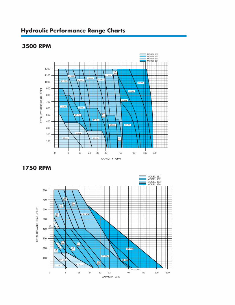
Hydraulic Performance Range Charts
3500 RPM
1200
1100
1000
900
800
700
600
500
400
300
200
100CT914
CT-821
CT912
CT-111
CT-211
CT-715
CT914
0 8 16 24 32 40 60 80 100 120
MODEL 152MODEL 151
MODEL 153MODEL 154
CT-994
CT-993
CT-992
CT-991CT-913
CT-713
CT-922
CT-923
CT-723
TO
TA
L D
YN
AM
IC H
EA
D -
FE
ET
CAPACITY - GPM
CT-212
CT-911
CT-811
CT-921CT-725
CT924
1750 RPM
500
600
700
800
400
300
200
100
TO
TA
L D
YN
AM
IC H
EA
D -
FE
ET
CT921
CT821
CT - 715
CT723
CT912
CT922
CT923
CT713
CT - 212
0 8 16 24 32 32 40 80 100 120
CAPACITY–GPM
CT - 924
CT - 725
CT811
CT - 211
CT - 1 11
CT-992
CT-994
CT-993
CT-914
CT913
CT911
MODEL 152MODEL 151
MODEL 153MODEL 154

Modular Design
Materials of Construction
PUMP MATERIAL CODE*PART 14 19 22
316 STAIN. DUCTILE ALLOY 20CASING STL. IRON ASTM A743
ASTM A743 ASTM A395 CN7M
316 STAIN. DUCTILE ALLOY 20IMPELLER STL. IRON ASTM A743
ASTM A743 ASTM A395 CN7M
316 STAIN.SHAFT STL. STEEL CARPENTER
AISI 316 AISI C1045 20
316 STAIN.** ALLOY 20**CHANNEL STL. CAST IRON ASTM A743
RINGS ASTM A743 ASTM A48 CN7M
316 STAIN. HDN. STAIN.SLEEVE STL. STL. CARPENTER
AISI 316 ASTM A276 20
316 STAIN. DUCTILE ALLOY 20GLAND STL. IRON ASTM A743
AISI 316 ASTM A395 CN7M
316 STAIN. DUCTILE ALLOY 20STUFFING STL. IRON ASTM A743
BOX ASTM A743 ASTM A395 CN7M
Pumps come standard with packing.– Braided acrylic with graphite/TFE
(Teflon lantern ring furnished upon request.)
*Other material combinations available.**Chromium oxide ceramic coated sealing surfaces.
APCO-CHEM offers for standard construction, 2 power frames, 3 shafts, 2 stuffing box covers, 10 impellerand channel ring sets and 4 casings for maximum interchangeability.
Two stage utilizes single stage parts with exception of shaft and casing.Duplex utilizes two stage parts with exception of the casing.
Model 151Single Stage
Model 152Single Stage
Model 153Two Stage
Model 154Duplex
1 Frame1 Stuffing Box3 L.H. Rings3 Impellers3 R.H. Rings1 Casing1 Shaft
CT111CT211CT212
CT713CT715CT811CT911CT912CT913CT914
CT723CT725CT821CT921CT922CT923CT924
1 Frame1 Stuffing Box7 L.H. Rings7 Impellers7 R.H.
Rings3 Casings
CT991CT992
CT993CT994
Model 153 Model 154

-200 0 200 400 600WORKING TEMPERATURE (°F.)
MAX.
CAS
E WOR
KING
PRE
SSUR
E (P.S
.I.G)
(Diff
eren
tial p
ressu
re p
lus su
ction
pre
ssure
)
0
100
200
300
400
MODEL 151
A & C
B
-200 0 200 400 600WORKING TEMPERATURE (°F.)
0
100
200
300
400
MODEL 152
MAX.
CAS
E WOR
KING
PRE
SSUR
E (P.S
.I.G)
(Diff
eren
tial p
ressu
re p
lus su
ction
pre
ssure
)
A & C
B
-100 0 200 400 600WORKING TEMPERATURE (°F.)
MAX.
CAS
E WOR
KING
PRE
SSUR
E (P.S
.I.G)
(Diff
eren
tial p
ressu
re p
lus su
ction
pre
ssure
)
0
100
200
300
400
MODEL 153/154
500
600A & C
B
Pressure & Temperature Capability
Construction Details
Code For Pressure – Temperature ChartA B C
316 SS Ductile Iron Alloy 20
Maximum Temperature Limitations for Pumped Liquid
NOTES:1. Pumps with standard mechanical seals on continuous duty water applications
MUST NOT exceed 180° F without providing cooling at the stuffing box.Special seal face materials will increase this limit – refer to factory.
2. Pumps with packing on water applications MUST NOT exceed 250° F withoutproviding cooling at the stuffing box.
3. For temperatures above 300° F in models 152, 153 and 154, the centerlinecasing support is recommended.
Gen
eral
Stuf
fing
Box
Shaf
tBe
arin
gs
*Model 151 has 2 taps.**Optional
TAPPED OPENINGS
NO. OFTAP SIZE
PURPOSE151 152-3-4TAPS
Lantern Ring Connection 1 B NPSF B NPSF
Frame Adapter Drain 1* A NPSF A NPSF
Discharge Gauge Connection** 1 B NPT B NPT
Suction Gauge Connection** 1 B NPT B NPT
PUMP MODELS
DESCRIPTION 151 152-3-4
Mechanical Seal – without stuffingbox cooling (See Note 1). 300° F 300° F
Mechanical Seal – with water cooledstuffing box and water jacketed frame. N/A 500° F
Packing – without stuffing box cooling(See Note 2). 300° F 300° F
Packing – with water cooled stuffingbox and jacketed frame. N/A 500° F
PUMP MODEL
SERIES 150 151 152 153 154
Dia. at Impeller M" 1D"
Dia. at Sleeve G" 1A"
Dia. Between Bearings 1L" 2D"
Dia. at Coupling End G" 1D"
Keyway I Sq. B Sq.
Maximum Deflection 0.002"
Radial Bearing 306 309
Thrust Bearing 5306 5309
Bearing Centers 5.37" 6.87"
Radial Brg. and 1st Stg. 5.37" 6.56"Center
Radial Brg. and 2nd Stg. 5.75" 6.87"Center
Min. B10 Bearing LIfe 2 years
PUMP MODEL
SERIES 150 151 152 153 154
Discharge Flanges (300) 1 1A 1A 2
Suction Flange 1A 3 3 3
Number of Stages 1 1 2 2
Casing Wall Thickness A F C C
Nominal Impeller Dia. 4A – 6 –
Corrosion Allowance D
Impeller Clearance 0.005' to 0.007'
Rotation From CPLG CW
Bore 1C" 2A"
Depth 2" 2F"
O.D. Sleeve 1D" 1C"
Packing Size E Sq. F Sq.
Distance To First Obstruction 1O 2L
Total Rings 5 5

NOTE: Aurora Pump reserves the right to make revisions to its products and their specifications, and to this bulletin and related information without notice.
AP-
150
(KC
C P
RIN
TED
IN U
.S.A
.)
The contractor shall furnish (andinstall as shown on plans) AuroraModel (151 - 17-1/2” A.N.S.I.horizontal flexible coupled) (152 -23-1/2” A.N.S.I. horizontalflexible coupled) (153 - 23-1/2”,154-23-1/2” A.N.S.I. horizontalflexible coupled) back pull outregenerative turbine pump(s)size……… x ……… x……… Thepump shall be constructed with(ductile iron) (316 stainless steel)pressure containing parts having aminimum tensile strength of(60,000 PSI ductile iron) (80,000PSI 316 stainless steel) and shallbe of sufficient thickness to with-stand stresses and strains at fulloperating pressures. Casings shallbe subject to a hydrostatic pres-sure test at 150% of the specifiedduty point. The pump shall becapable of delivering at designconditions a capacity of………G.P.M. when operating against aTotal Dynamic Head of………
feet, with a temperatureof………;°F, ……… Liquidspecific gravity ………Pump shalloperate at a maximum synchro-nous speed of . . . R.P.M. A unitoperating at a lesser rotative speedwill be considered, but in no eventwill a pump operating at morethan the maximum speed specifiedbe acceptable. Each pump is to befurnished with a (standard) (watercooled) stuffing box with(………mechanical seal) (packing).The unit must be equipped with(316 stainless steel) (440Chardened stainless steel, packpumps) pin locked shaft sleeve thatextends the length of the stuffingbox. The pump shaft extensionshall be “O” ring sealed from thepumped liquid. The discharge shallbe in a vertical position and thepump shall be self-venting. Theimpeller shall be hydraulically self-centering and no external adjust-ment shall be necessary. Pump andmotor are to be mounted on a
common (A.N.S.I. cast iron) (steel)baseplate. The pump shaft shall bemade of high grade……… steel orequal. The minimum diameteracceptable will be………”. Theshaft shall be installed in a cast ironpower frame. Pumps shall have ashaft designed for .002” deflectionat the face of the stuffing box withthe pump running under maximumload condition. (Oil) (Grease)lubricated ball bearings, having a 2-year minimum life (AFBMA B-10)under the maximum condition ofload protected by separate oil sealsand slingers, shall be used. Thepump shall be flexible coupled tostandard horizontal NEMA………HP………phase……….Hertz………volts……… RPM(drip-proof) (totally enclosed)(explosion-proof) motor. Align-ment shall be checked in accord-ance with the standards of theHydraulic Institute after installationand there shall be no strain trans-mitted to the pumps.
General Dimensions and Engineering Specifications
B
C A
1-1/4
HB
HF
4-1/2
1-1/4 1-1/2
HA
HE
4-HHHOLES
D
HG
HE
X
Y
SP
DIMENSIONS DETERMINED BY MOTOR
MODELMOTOR BEDPLATE
MOTOR FRAME SIZE C MAX HA HB HG HF HH HE
151 1T 56 - 145T 10 35 3 32A C 4
151 2T 182 - 215T 12 39 3B 36A C 4A
152 1 143T - 215T 12 45 3C 42A C 4A
153 2 245T - 286TS 15 52 4D 49A C 6
154 3 324T - 365TS 18 58 4C 55A 1 7
PUMP DISCHARGE SUCTIONMODEL SIZE SIZE SIZE A D X Y B SP
151 1x1Ax6 1 1A 17A 5B 6A 7B 4 3A
152 1Ax3x6 1A 3 23A 8B 8A 12A 4 3A
153 1Ax3x6 1A 3 *23A 8B 8A 12A 4* 3A
154 2x3x6 2 3 *23A 8B 9A 12A 4* 3A
When optional 300# flange is used, add I" to Model 153 and O" to Model 154.
HYDRA
ULI
C
19
INSTIT
UTE
17
MARKETING & SALES:800 AIRPORT ROAD • NORTH AURORA, ILLINOIS U.S.A. • 60542PHONE: (630) 859-7000 U.S.A./CANADA FAX: (630) 859-7060 WORLDWIDE FAX: (630) 859-1226
AURORA MFG. PLANT: 800 AIRPORT ROAD • NORTH AURORA, ILLINOIS U.S.A. • 60542
SALES OFFICES IN ALL MAJOR CITIES AND COUNTRIESRefer to “Pumps” in yellow pages of your phone directoryfor your local Distributor
— Your Authorized Local Distributor —
ISO90
01
QUALITY SYSTEM CERTIFIED
AURORAPUMP