15 ae frequency
TRANSCRIPT

Analogue ElectronicsPaolo Colantonio
A.A. 2015-16
Università degli Studi di Roma Tor VergataDipartimento di Ingegneria Elettronica

P. Colantonio – Analogue Electronics 2|17A.A. 2015/16
The frequency behavior of a BJT amplifier• The hybrid ‐model gives a better representation at high frequencies for the BJT
• At medium frequency the hybrid ‐model and the hybrid model should beequivalent

P. Colantonio – Analogue Electronics 3|17A.A. 2015/16
Model equivalence
gm
rb’e
rb’c
rbb’
gce

P. Colantonio – Analogue Electronics 4|17A.A. 2015/16
Typical values
IC VCE T
gm n10 mA/V
rbb’ n102
rb’e n103
Cb’e (Ce) n102 pF
Cb’c (Cc) n pF
hfe n100
hie n103
Legend• means increases• means decreases• means is stable

P. Colantonio – Analogue Electronics 5|17A.A. 2015/16
Identification of the BW of an amplifier• The direct methods requires to evaluate the amplifier transfer function
• The cut‐off frequency are found by solving the equation
• Being G0 the medium frequency amplifier gain• Obviously, the approach is rigorous, but not even simple…
• Two simplified methods are typically adopted• The poles method• The method of time constant in open or short circuit

P. Colantonio – Analogue Electronics 6|17A.A. 2015/16
The poles method• If the capacitance present in the circuit are not interacting, thus for each capacitor
CX is computed the time constant
• Being RX the equivalent resistor seen by CX
• The low cut‐off frequency is given by:
• The high cut‐off frequency is given by:
The bandwidth is approximated in excess

P. Colantonio – Analogue Electronics 7|17A.A. 2015/16
The method of time constant in o.c. or s.c.• If the capacitance present in the circuit are interacting, then the following approach
is adopted
• The low cut‐off frequency is given by:
• The high cut‐off frequency is given by:
• Being• n,sc the time constant associated to the capacitance Cn, assuming all the
other capacitance as short circuit• n,oc the time constant associated to the capacitance Cn, assuming all the
other capacitance as open circuit
The bandwidth is approximated in defect

P. Colantonio – Analogue Electronics 8|17A.A. 2015/16
Bandwidth
fL fH
poles method poles method
s.c. or o.c. time constant method

P. Colantonio – Analogue Electronics 9|17A.A. 2015/16
Cascaded amplifiers• Capacitive coupling between amplifier stages
• A two-stage DC-coupled amplifier

P. Colantonio – Analogue Electronics 10|17A.A. 2015/16
Cascode• To obtain a large bandwidth, a cascode configuration is usually adopted• It is realized by a CE amplifier loaded by a CB amplifier

P. Colantonio – Analogue Electronics 11|17A.A. 2015/16
Cascode• The AC circuit becomes the following
• For the analysis at medium frequency, starting from the CB amplifier:
P. Colantonio – Analogue Electronics 12|17A.A. 2015/16
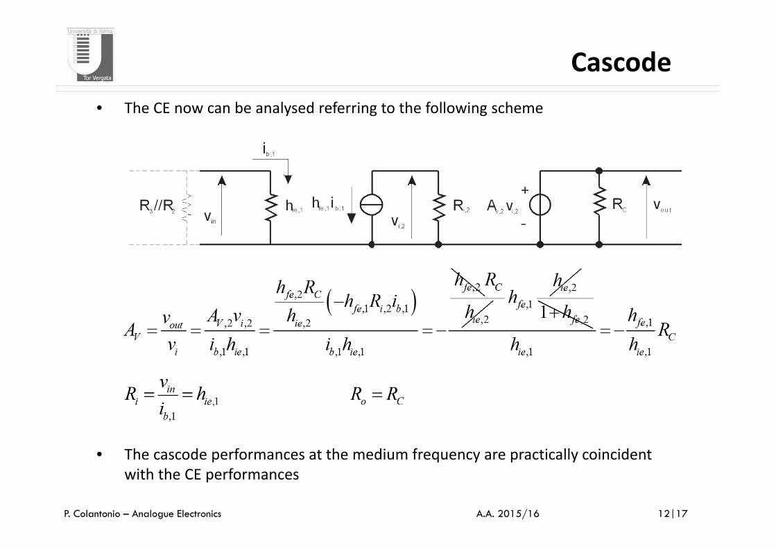
Cascode• The CE now can be analysed referring to the following scheme
• The cascode performances at the medium frequency are practically coincident with the CE performances

P. Colantonio – Analogue Electronics 13|17A.A. 2015/16
Cascode• For the analysis of the bandwidth, we can analyse what is the behaviour of a CE
and CB separately, by using the hybrid model
CE
• For the determination of the high frequency limitation, applying the methods of time constant it follows

P. Colantonio – Analogue Electronics 14|17A.A. 2015/16
Cascode
• The high cut‐off frequency of a CE is given by
• To have a large gain, a big value of RC is required, which however reduces the bandwidth• The adoption of the CB as loading impedance, allows to reach the same voltage gain (as
previously saw) but presenting to the CE stage an equivalent resistance (RC) much lower

P. Colantonio – Analogue Electronics 15|17A.A. 2015/16
Cascode• Assuming now the CE loaded by the CB, with an input resistance very low

P. Colantonio – Analogue Electronics 16|17A.A. 2015/16
CascodeCB
• For the determination of the high frequency limitation, applying the methods of time constant it follows

P. Colantonio – Analogue Electronics 17|17A.A. 2015/16
Cascode• The cascode high cut‐off frequency is given by