1444 ieee transactions on smart grid, vol. 3, no. … paper/p76_matlabi... · co-simulation of...
TRANSCRIPT
1444 IEEE TRANSACTIONS ON SMART GRID, VOL. 3, NO. 3, SEPTEMBER 2012
GECO: Global Event-Driven Co-SimulationFramework for Interconnected Power System and
Communication NetworkHua Lin, Student Member, IEEE, Santhosh S. Veda, Student Member, IEEE,
Sandeep S. Shukla, Senior Member, IEEE, Lamine Mili, Senior Member, IEEE, and James Thorp, Life Fellow, IEEE
Abstract—The vision of a smart grid is predicated upon perva-sive use of modern digital communication techniques to today’spower system. As wide area measurements and control tech-niques are being developed and deployed for a more resilientpower system, the role of communication network is becomingprominent. Power system dynamics gets influenced by the commu-nication delays in the network. Therefore, extensive integration ofpower system and communication infrastructure mandates thatthe two systems be studied as a single distributed cyber-physicalsystem. This paper proposes a power system and communica-tion network co-simulation framework (GECO) using a globalevent-driven mechanism. The accuracy is tunable based on thetime-scale requirements of the phenomena being studied. Thisco-simulation can improve the practical investigation of smartgrid and evaluate wide area measurement and control schemes. Asa case study, a communication-based backup distance relay pro-tection scheme is co-simulated and validated on this co-simulationframework.
Index Terms—Co-simulation, event-driven, wide area protectionand control.
I. INTRODUCTION
T HE MODERN power system has advanced to the pointwhere the system can no longer be operated without
wide area control systems [1], [2]. The advent of systeminfrastructure restructuring and the vision of smart grid havefurther prompted the concomitant control systems to reach anunprecedented level of sophistication. It can be predicted thatmore such state-of-the-art computation and communicationtechniques will be integrated into the power system to carrythe control system from local to wide area scope. As a result,the power system will be operated and controlled with thehelp of an underlying communication network where largeamount of information will be exchanged. This new interde-pendent configuration of the power system and communicationnetwork brings challenges which have not been seen before.The structure of the communication network to be laid out in
Manuscript received October 09, 2011; revised February 02, 2012; acceptedMarch 14, 2012. Date of publication May 15, 2012; date of current version Au-gust 20, 2012. This work was supported in part by the National Science Foun-dation under Grant NSF EFRI-0835879. Paper no. TSG-00572-2011.The authors are with the Department of Electrical and Computer Engineering,
Virginia Tech, Blacksburg, VA 24061 USA (e-mail: [email protected]; [email protected]; [email protected]; [email protected]; [email protected]).Color versions of one or more of the figures in this paper are available online
at http://ieeexplore.ieee.org.Digital Object Identifier 10.1109/TSG.2012.2191805
the national power grid, the communication protocols to beused, the physical media, the distributed algorithms to makedecisions on power system state and required control actions,the hierarchy of communication and control network, and manyother issues remain unsettled to date. This mandates that weneed power system and communication network co-simulationas opposed to only a stand-alone power grid simulator. It isprudent that we take into account these considerations duringthe designing phase.A report prepared by the US Department of Homeland Se-
curity [3] advocates the need for a national power grid sim-ulator. It is recommended that such a simulator should allowfor modeling various possible disruptive events, studying inter-dependencies between the power grid and other critical infra-structures, and allow for planning and design of smarter capa-bilities of the national grid to enhance resilience, robustness,integration of renewable energy sources. Even though this re-port does not specifically deal with the embedded computationaland communication capabilities envisioned for the future smartgrid, there are already many efforts worldwide to enable variouspower grids to communicate data in real-time over wide areas,and use networked and distributed control to avoid various dis-astrous scenarios including blackouts, unwarranted generationshutdowns, unwarranted frequency excursions, inter-area oscil-lations, voltage instability, and so on.If we can implement an effective, scalable and efficient power
grid and communication network co-simulator, we can designwide-area measurement and control schemes that have hithertonot been considered yet, and easily simulate its effectivenessand optimize the design and cost. For instance, PMU-basedwide area measurement systems (WAMS) would have readilybenefit from such a simulator [4]. However, it is not an easy taskto get this done, as there is a mismatch in the models of com-putation in the two simulation worlds [5]. Continuous time sim-ulation of power system and discrete event simulation of com-munication network have to be seamlessly integrated and this isthe key issue that is being discussed in this paper.The following paper is organized as follows: Section II sum-
marizes the related work. Section III presents the co-simulationframework GECO and an implementation of it using PSLF andNS2. A communication-based backup relay protection schemeis discussed as a case study on GECO in Section IV. Severalco-simulation scenarios and simulation results are shown inSection V to demonstrate the effectiveness of our method.Section VI summarizes the discussion and concludes the paper.
1949-3053/$31.00 © 2012 IEEE
Downloaded from http://www.elearnica.ir

LIN et al.: GECO: GLOBAL EVENT-DRIVEN CO-SIMULATION FRAMEWORK 1445
TABLE ICOMPARISON OF INTEGRATED POWER/NETWORK SIMULATORS
II. RELATED WORK
Co-simulation of heterogeneous systems which integratesdifferent simulation models is not a rarity in other researchdomains [6]–[9]. However, it is relatively new for powersystem applications. There has been some research on powersystem control analysis with consideration of communicationnetworks [10], [11]. However, owing to lack of proper mod-eling tools, the characteristics of the communication networksin their research have to be either largely simplified or somevery optimistic assumptions have to be made [12]. Apparently,one-sided simulation is insufficient for the investigation offully integrated power system and communication network.In the progress of power system restructuring, co-simulationof power system and communication network has graduallybecome researchers’ favorite. Table I summarizes the relatedwork in this new research area.EPOCHS [13] pioneered the efforts to build a power system
modeling tool with attention to the underlying communicationnetwork. The EPOCHS approach is based on federated dynamicsimulation using multiple components. Three off-the-shelf sim-ulators: PSCAD/EMTDC for transient time scales, PSLF forpower system modeling, and NS2 for computer network mod-eling, are configured as an integral platform. A carefully de-signed software mediator, called “runtime infrastructure” (RTI),is responsible for interfacing and synchronization between theindividual simulators by allowing them to exchange data period-ically. The synchronization algorithm is a simple time-steppedmethod. In this method, the individual simulators run respec-tively but halt at fixed synchronization points where informationis exchanged between simulators. However, if certain systemevent which requires interacting among those simulators hap-pens between the synchronization points, the event has to bebuffered in a cache and wait to be processed until the next syn-chronization point. Therefore system errors could be accumu-
lated and hamper the simulation fidelity, in particular if the ap-plication is time-critical and requires numerous interfacing be-tween the power system and communication network. The usersof EPOCHS will face a dilemma between precision and effi-ciency when choosing the proper size of a synchronization step.A work similar to EPOCHS is reported in [14] where the au-
thors try to improve the synchronization algorithm. The powersystem is modeled using DEVS formalism and integratedwith NS2. Theoretically, this hybrid simulation environmentgives better synchronization than EPOCHS since DEVS isdesigned for discrete event system modeling. However, theDEVS package that has been used is designed for generaldiscrete event system and not for power system simulationsspecifically. Therefore, the users have to implement their owncode conforming to DEVS specification for power systemdynamic simulation which may affect the reliability of powersystem models and scalability of the hybrid simulation. At thesame time, since most commercial power system modeling andsimulation tools do not adopt this approach, this implementa-tion cannot be readily applied to federations of simulators.In [15], an integration of MATLAB Simulink and OPNET
is reported to study the Information & Communication Tech-nology (ICT) architecture’s impact on the reliability of WAMSapplications. The authors use OPNET to model a detailed hi-erarchical ICT infrastructure which includes all the processespertaining to phasor data collection. The communication delaysare tuned to study the sensitivity of PMU-based applications.Although this paper presents an interesting way showing howto use integrated simulation of power system and communica-tion network to study system interdependence, information onsynchronization method and the actual integration of the twosimulators have not been addressed.In [16], an integration of Virtual Test Bed (VTB) software and
OPNET called VPNET is introduced for simulating remotelycontrolled power electronic devices in the system. The synchro-

1446 IEEE TRANSACTIONS ON SMART GRID, VOL. 3, NO. 3, SEPTEMBER 2012
nization method used in this paper is similar to the EPOCHS’smethod. The co-simulation coordinator samples value from bothsimulators based on a global simulation time step. Therefore itaccumulates the same kind of system errors as EPOCHS. More-over, VTB is a software tool for simulating power electronicsand energy systems, and so may not scale well to fit large scalepower networks. So far as we are concerned with a few powerdevices, the magnitude of inter-device communications may notbe significant. In the case study reported in this paper, the net-work infrastructure consists of only two nodes. A similar workcalled PowerNet is reported in [17] which integrates Modelicaand NS2. The synchronization method and scalability featureare about the same as described above.An extension of OPNET to simulate wide area communica-
tion network in power system is built in [18]. In this frame-work, the power system dynamic simulation is simplified as avirtual demander. Whenever the demander requests to transmitdata on the network, it suspends itself and creates a packet inOPNET. OPNET will simulate the total communication delayof this packet and report it back to the virtual demander. At thistime, the virtual demander will reactivate itself and simulatefor the same time as the communication delay before furtherprocessing. In this way, no synchronization errors are accumu-lated. But this method is only suitable for one agent, one re-quest scenario. If there are multiple agents in the system willingto transmit data within the same time period, this frameworkwould fail due to single-threaded implementation. To simulatea complex hybrid system, alternative solutions are necessary.Another kind of integration of power system and communi-
cation network is reported in [19] where a SCADA cyber secu-rity test bed is designed. The research focus of this test bed isto assess the vulnerability of the communication infrastructureof the power system to cyber attacks, and therefore static powersystem simulation is sufficient and synchronization considera-tions can be neglected. Moreover, the test bed runs on severaldifferent computers. The power system is simulated in Pow-erWorld software on an individual server. There are also sev-eral computers called network clients which can read data fromPowerWorld through a VPN network and a real-time networksimulator RINSE. The network attacks can be generated andstudied as part of network simulations and the power system dy-namics is not a big concern here. A very similar SCADA cybersecurity test bed is proposed in [20] which integrates Power-World and OPNET.Most of the works reported in Table I involve the reuse of
existing off-the-shelf software. This is a natural choice sincethey are more reliable and scalable as long as they can beproperly modified and customized. Rewriting new simulationengines from scratch is costly and time-consuming. Otherpossible options include software/hardware hybrid emulationenvironments or hardware testbeds. For example, since thescale of some SCADA systems is smaller than WAMS ap-plications, it is possible to build emulation environments forSCADA testbeds. In [21], [22], a SCADA testbed PowerCyberusing scale-down field devices to represent the real system isdocumented. However, our co-simulation framework GlobalEvent-driven CO-simulation platform (GECO) aims at themodeling and simulation for the wide area power systemmonitoring, protection and control schemes. Building hardware
emulation system at the national level is prohibitively expen-sive. Even if it is possible to make assumptions to scale downthe system, the fidelity of the emulation cannot be guaranteed.For example, the communication infrastructure dedicated tothe power system could be isolated from other overwhelmingnetworks such as Internet. The communication topology, proto-cols, routing scheme and background traffic at different levelscan be significantly different.Another attractive solution is to use real-time simulators to
represent the real world system. RTDS is a well-known real-time power system simulator which is capable of performingclosed loop testing of devices [23]–[25]. RTDS simulation re-lated to IEC 61850 communication has been reported in [26].However, the scale of the hardware in the closed loop is limitedto local scope. Deploying RTDS simulation results on a largescale distributed network is difficult. Therefore integrating an-other real-time communication network simulator with RTDSwill be a better option. But real-time simulators allowing openaccess are always rare so that this kind of real-time co-simula-tion implementation has not been published. Synchronizing tworeal-time simulators is also a challenging problem as both simu-lators are synchronized to real world clock. This requires that areal-time simulation coordinator be designed to exchange infor-mation between the simulators. Nevertheless, Real-time co-sim-ulation platform will draw more interest in the future.
III. CO-SIMULATION FRAMEWORK
The key issue of the power/communication co-simulationframework is to accurately synchronize the simulation time intwo distinct simulation models. In this section, the simulationtechniques for power system and communication network willbe briefly reviewed. Then the co-simulation framework willbe introduced based on careful analysis of those simulationtechniques.
A. Power System Dynamic Simulation
Power system dynamic simulation is commonly modeledas a continuous time system simulation. In a continuous timesystem, the system state variables change in a continuousmanner with respect to time. Typically the system dynamicsis represented by a set of differential equations in which thetransitions between continuous state variables are defined.For simple cases, the differential equations can be solvedanalytically to get closed form solutions. However in mostcases such closed form solutions are not available. Instead,numerical algorithms are studied for general cases. Usuallythe differential equations are discretized and the time base isdivided into small steps. The next system state is derived fromcurrent system state. Then the small variations of the statevariables are integrated to approximate the system trajectory.The discretized time step is often very small so that the systemvariables do not have an abrupt transition within the time step.An example of this numerical algorithm for power system
dynamic simulation is illustrated in Fig. 1. The system is ini-tialized by solving power flows which calculates initial systemstate values. Then the simulation enters a loop which representsthe main part of the algorithm. Within this loop, the network

LIN et al.: GECO: GLOBAL EVENT-DRIVEN CO-SIMULATION FRAMEWORK 1447
Fig. 1. Example of the power system dynamic simulation.
boundary variables for dynamic models connected directly tothe system network are calculated. Then the secondary variablesof dynamic models are calculated from system state variables. Acomplete iteration in this loop is completed by calculating statevariable derivatives and integrations. At this point, the systemtime is advanced by a preset time step or a time calculated fromthe current system state. The loop continues until the simulationreaches the stop time or an accept state. Alternatively, if the sim-ulation loop is expanded on a time axis which is shown in Fig. 1,a sequence of discrete iteration rounds can be found with smalltime intervals in between. This sequence actually shows that acontinuous time system in fact is numerically solved in a dis-crete manner.
B. Communication Network Simulation
Communication network simulation is usually performedusing a discrete event-driven method. Discrete event-drivensimulation is suitable for systems whose state is only subjectto change due to discrete events. The occurrences of eventsare usually unevenly distributed with respect to time. Timediscretization into small time intervals as done in continuoustime systems cannot be appropriately applied to discrete eventsystems since the time step is difficult to select. If the time stepis selected too small then it will waste simulation times sincesystem state remains unchanged during many consecutive timesteps. If the time step is selected too long, then many eventscould be missed during a single time step. Instead, in discreteevent-driven simulation, the system time instead hops betweenevents. An event scheduler is designed to record current systemtime and also to maintain an event list. Event list is a queuethat stores system events with timestamps in a chronologicalsequence. The scheduler initializes the system state and theevent list in the beginning of the simulation. When the simu-lation starts the scheduler proceeds with the event on top ofthe list and sorts out the relevant processes. Then the scheduleradjusts the system time directly to the timestamp of the nextevent in the list. The entire simulation stops when the systemtime reaches the stop time or the system reaches a certainstate. Fig. 2 shows an example of a communication network
Fig. 2. Example of the communication network simulation.
simulation that uses event-driven method. When the simulationstarts, node 1 sends a packet to node 4 via node 2. The firstevent in the list should be “node 1 sends a packet to node 2”with its timestamp. A receiving event by node 2 is predictedbased on the communication link properties. Then the secondevent “node 2 receives a packet from node 1” will be createdand placed in the event list. The simulation will continue thisway until the ending criteria is satisfied.
C. Co-Simulation Framework
Since the simulation techniques for power system and com-munication network are different, synchronization mechanismbetween them is the most crucial issue leading to a successfulco-simulation design. An intuitive method is to use explicittime-stepped synchronization [13] as shown in Fig. 3. Inthis method, several synchronization points are predefined.In Fig. 3, the top axis represents the power system dynamicsimulation process and the bottom axis represents the commu-nication network simulation process. When the co-simulationstarts, two processes run independently until both of themreach a synchronization point, as denoted by dashed verticallines. It is here that the two processes suspend themselves andexchange information. Typical interaction information includespower devices uploading data to control center or smart relayreceiving a remote command to trip the circuit breaker. Afterthat, two processes restart and repeat the synchronization asdone before.This synchronization method can easily bring in simulation
errors. If an interaction request appears between the synchro-nization points, it has to wait until the next synchronization tobe processed. This problem is indicated by “Error 1” and “Error2” in Fig. 3. These errors create unwanted time delays whichdo not exist in a real system and might accumulate over time.Theoretically, each error can be the same as one synchroniza-tion time step.A new co-simulation framework is accordingly proposed
which avoids these synchronization errors. Our co-simulationruns globally in a discrete event driven manner as shownin Fig. 4. Since the power system dynamic simulation is infact solved in discrete manner as shown in Fig. 1, each ofthe iteration rounds is treated as a special discrete event in

1448 IEEE TRANSACTIONS ON SMART GRID, VOL. 3, NO. 3, SEPTEMBER 2012
Fig. 3. Synchronization with errors.
Fig. 4. Event-driven synchronization without errors.
this framework. A global event scheduler is designed as theglobal time reference and coordinator. A global event list isalso prepared by mixing up the power system iteration eventswith other communication network events according to theirtimestamps. Therefore, only one event process is allowed torun at the same time. This is illustrated by the only axis inFig. 4. The global scheduler checks the global event list toidentify if the next event is a power system simulation eventor a communication network event and yields the controlaccordingly. More importantly, the simulation processes cansuspend themselves after each event and yield the controlback to the global scheduler. In this way whenever there isan interaction request, it can be processed immediately by theglobal scheduler without unnecessary time delay. Both errorsin Fig. 3 are eliminated in this framework.
D. Formalism
It is necessary to show that our global even-driven co-simula-tion does not undermine the simulation integrity in each of theindividual simulator since all the events are mixed up. In thissubsection, we will verify it using a formal approach.Discrete Event System Specifications (DEVS) is a popular
formalism to model and analyze general discrete event systems.There are also many other equivalent formalisms but DEVS is
more suitable for this co-simulation framework. It is defined asa 7-tuple [27]:
(1)
where:
is the set of input events;
is the set of output events;
is the set of system partial states;
is the lifespan function of the partial state;
is the internal transition function;
is the external transition function;
is the output function.
is the set of totalstates including which is the time elapsed since last transition;
The interpretation of (1) for a communication network simu-lation is straightforward where are still the system input/output; is the system state when a certain discrete event isbeing processed; represents the time delay between the cur-rent event and the next event in the event list. stands for therelevant processes associated with an event where standsfor the impact of the input to the system state. Even-driven sim-ulation is commonly used for the system which can be modeledby DEVS.It has also been shown that the power system dynamic simu-
lation can be modeled by DEVS [14]. For this particular case,is the set of system state variables (voltage, current, etc.) aftereach iteration round. represents the iteration time step and
stands for the system change after the integration of eachtime step.The co-simulation framework in fact couples the power
system and communication network together. That is: theoutput event of the power system simulation is the input eventof the communication network simulation and vice versa.From the DEVS formalism point of view, these two atomicDEVS systems actually form a coupled-DEVS which is another7-tuple [27]:
(2)
where:
is the set of input events;
is the set of output events;
is the name set ofsub-components;
is the set of DEVSs that formthe coupled-DEVS;
is the set of external inputcouplings;
is the set of internal couplings;

LIN et al.: GECO: GLOBAL EVENT-DRIVEN CO-SIMULATION FRAMEWORK 1449
is the set of external outputcouplings;
Select is a tie-breaker function fortime conflict of events.
The couplings define how the atomic DEVSs are connectedto form a coupled-DEVS. For the co-simulation framework,will be which represents power system and communi-cation network respectively. will be the DEVS modelsfor them. EIC and EOC will be both empty and ITC will be
.It has been proved that DEVS is closed under coupling which
means a coupled-DEVS is equivalent to a DEVS . Theproof can be done by construction [27] where:
The new is the lifespan of the new partial state con-sidering that event from other DEVSs can potentially reduceits own original lifespan. This equivalent DEVS can alsobe simulated using event-driven method. Therefore the integrityof the individual simulators still holds under our co-simulationframework. The proof also indicates that global event-drivensimulation is an effective approach for the interconnected powersystem and communication network.
E. Implementation
The co-simulation framework is realized by carefully inte-grating two individual simulators: GE’s Positive Sequence LoadFlow (PSLF) and Network Simulator 2 (NS2). The integrationinvolves major modifications and extensions on both parts. Thesimulators we choose are the same as EPOCHS [13] but ourinternal design is different and the difference will be shown inlater sections through comparison of simulation results.PSLF is a power system simulator designed byGEwhich pro-
vides both steady-state and dynamic power system simulations.PSLF is able to simulate a system with up to 60 000 buses and isequipped with a rich library of power system dynamic models.The software is written in Java and provides plenty of APIs inthe format of a script language called EPCL for further cus-tomized extensions. New models written in EPCL can also beintegrated into the existing software package. EPCL can accessthe runtime simulation data and change the simulation settingsas needed. Although PSLF is not an open-source software, itsdesign feature enables users to build flexible extensions.NS2 is a well-known communication network simu-
lator aiming at the evaluation of network performance. It is
Fig. 5. The structure of the co-simulation framework.
open-source and thus widely used in networking research do-main. NS2 is basically a general discrete event simulator witha rich library of network models which covers four protocollayers in the network reference model excluding the physicallayer. The core of NS2 is written in C++ which is complex.Therefore a script language called Object Tcl (OTcl) is pro-vided to users for easier simulation configuration and reuse. Aframework called “OTcl linkage” links the OTcl codes to thebackground implementation by C++. Following this way, userscan write and compile new network protocols or models in C++and manipulate them in OTcl.Fig. 5 shows the structure of our co-simulation framework
implementation. The global scheduler and global event list arederived directly from the counterpart in NS2 so that a subcom-ponent in NS2 drives the whole co-simulation overall. A bi-di-rectional interface is designed between NS2 and PSLF to ex-change information.On the PSLF side, a new dynamic model “epcmod” is added
as the main port to the NS2. Within each iteration round, thismodel updates all the power data for NS2 and receives feed-backs from NS2 to change the settings of the power system ac-cordingly. After each round, it is also able to suspend the PSLFsimulation, yield the control to the global scheduler and wait forthe command to run the next round.On the NS2 side, a new C++ class “tcl PSLF” is written
to drive the simulation of PSLF and coordinate the actionsin between. This new class is independent from all the othernetworking classes but still compiled together with othercomponents in NS2. When the simulation starts, this classpre-allocated a sequence of power system iteration roundsand put them in the global event list. When an iteration roundneeds processing, it sends the command to PSLF to restartthe suspended simulation. Potential network-based powersystem control strategies are designed in the power applicationclasses which are derived from class “Application” in NS2.These classes represent the functionalities of the softwareagents in current power devices such as digital relays, PhasorMeasurement Units (PMUs) and Intelligent Electronic Devices

1450 IEEE TRANSACTIONS ON SMART GRID, VOL. 3, NO. 3, SEPTEMBER 2012
Fig. 6. Distance relay protection zones.
(IEDs). The power data updated from PSLF will be distributedto them for further analysis. The software agents are able tocommunicate with each other through the network infrastruc-ture modeled in NS2 and control decisions are also made bythem. The communication protocols of the power applicationsare variants of existing famous network protocols like UDPand TCP. Minor changes are applied to UDP and TCP classesto enable them to carry power data.In the following sections, a communication-based distance
relay backup protection scheme will be introduced as a casestudy on this co-simulation platform. The purpose of the casestudy is to show what kinds of applications are suitable forco-simulation and how to use co-simulation to test a design andto study system interdependences.
IV. COMMUNICATION-BASED DISTANCE RELAYBACKUP PROTECTION
Distance (impedance) relays are usually utilized on the trans-mission system level. The operation of the distance protectionrelays is governed by apparent impedance which is the ratio ofthe magnitudes of voltage and current measured by the relay.When a short circuit fault occurs, the fault can be identified bya sharp drop in the measurement apparent impedance. Also thisimpedance tells the relay the distance from the fault location toitself.As shown in Fig. 6, it is common practice to assign three
protection zones for the distance relays. Zone 1 protection isthe primary protection for each distance relay. It covers about80%–90% of the length of the first transmission line as shownin Fig. 6. Zone 2 protection covers a little bit longer than zone 1extending beyond the bus 2 which is about 120% of the lengthof the first line. Zone 3 protection provides the longest coveragewhich includes the entire first line and about 80% of the secondline. By properly adjusting zone 1, zone 2 and zone 3 settingsthe distance relays can achieve both primary and backup pro-tection of the transmission lines. Usually zone 1 protection op-erates instantaneously while zone 2 and zone 3 protections areassociated with time delays as backups. It is common practiceto use longer time delay for longer reach of the relays so thatthey can provide effective system protection without unneces-sary power loss. The time delay can be as long as 1 second forzone 3 relays.Although the transmission systems with protective relaying
usually have the redundancy in the form of backup relays, itis reported that such a system still may suffer from differentkinds of failures. For instance, zone 3 backup relays work in a
time-delayed manner, the system may encounter instability is-sues during the delay. It is also known that zone 3 relays canactually erroneously trip due to hidden failures [28]. A hiddenfailure is usually rare but could happen due to software or hard-ware errors in the zone 3 relay. It may go unidentified for along time. However, such problems may manifest as extra sen-sitivity of a Zone 3 relay to even remote line overloading. Eventhough such an overloading might be transient, or might nothave reached a level where the zone 1 and zone 2 relays needto take action, an over active zone 3 relay may trip, starting asequence of other trips which may lead to a cascading failure[29], [30]. New protection techniques are being sought out tosolve this problem [31]–[37]Accordingly a new communication-based distance relay
backup protection scheme is introduced in this section thatleverages the present distance relay protection framework withthe addition of an underlying network infrastructure. Modernmicroprocessor-based digital relays are more reliable and effi-cient than traditional electromechanical ones, thus it is possibleto enhance them with software agents in order to design moreelaborate protection schemes. The distance relays can com-municate with each other through their software agents fromwhich a coordinated system protection scheme can be formed.By virtue of extensive communication new protection schemescould have faster backup relay protection and additional ro-bustness to prevent false tripping. Based on the communicationtype, two related protection schemes are discussed: supervisory(master to slave) and ad-hoc (peer to peer).
A. Supervisory Protection
In the supervisory protection scheme, distance relays areinter-connected as a network using a communication infra-structure and their functioning is coordinated through extensivecommunication links. A central protection controller called“Master Agent” coordinates the operations of the digital relaysin the system. Each distance relay has a software agent (SlaveAgent) associated with it. This software agent works as aninterface for information exchange between the Master &the corresponding distance relay. In this mode, the protectionscheme system is able to provide more secure protection byavoiding hidden failure induced false tripping.The primary protection for the distance relays remains the
same as the traditional distance protection scheme, while thebackup protection is different. In this scheme, when a backuprelay sees zone 2 or zone 3 faults, instead of waiting for a pre-settime delay to trip, the relay proactively collects informationfrom other relays to evaluate the status and make the decision.This procedure is done by communication between slave agentsand the master agent. Firstly, the slave agent whose associatedrelay sees a remote fault submits a request to the master agentfor decision. The master agent then asks other slave agents inthe fault zone to see if others see the fault as well. Based on thefeedback from other slave agents, the master agent sends thefinal decision to the original slave agents.Detailed operations of this master-slave mode supervisory
protection scheme are shown in Figs. 7 and 8 using a finite statemachine (FSM) representation. In the FSM, a circle representsa certain state. An arrow line represents a transition from one

LIN et al.: GECO: GLOBAL EVENT-DRIVEN CO-SIMULATION FRAMEWORK 1451
Fig. 7. FSM of supervisory protection: slave agent.
Fig. 8. FSM of supervisory protection: master agent.
state to another. There is a fraction associated with each transi-tion. The numerator position shows the event which causes thetransition and the denominator position shows the action takendue to that event.On the slave agent side, the relay starts from the “normal
monitoring” state and keeps monitoring the transmission line.If a zone 1 (local) fault is observed the relay should trip thetransmission line immediately. If a zone 2 or zone 3 fault (re-mote) is observed, the slave agent sends a decision request tothe master agent and enters the “wait for decision” state. If thefault disappears during the wait state, the slave agent would goback to the normal state and block whatever decision receivedfrom the master agent since this condition indicates the faultmay have been cleared by its own primary protection. If thefault persists and the slave agent receives a trip decision fromthe master agent, the relay should trip the line since the primaryprotection may have failed. If the slave agent receives a blockdecision from the master agent but still sees the fault, this indi-cates the relay may have a hidden failure or wrong setting. Thenthe slave agent should put the relay out of service and call formaintenance. In this manner the slave agents can both expeditethe backup protection and prevent hidden failure induced falsetripping.On the master agent side, when it receives a decision request
from a slave agent, it enters the “processing decision request”state. A group of relays which are entrusted with the fault areaare selected and queried by the master agent. When the softwareagents of the selected relays receive the queries, nomatter whichstate they are in, they should report if they see a fault back to the
Fig. 9. FSM of ad-hoc protection.
master agent. The master agent will try to make the final deci-sion when it receives a feedback. As long as a final decisioncould be made, the master should send it to the original slaveagent to take action. Fig. 8 only shows the master agent opera-tion for one slave agent. Actually when a fault happens in thesystem, multiple slave agents could send request to the masteragent. Therefore, the master agent should be a multi-threadedprogram which can handle all the requests simultaneously.Although there is extensive communication, the total commu-
nication time could still be shorter than the traditional time delaysettings for the zone 2 or zone 3 protections. However the timedelay associated with zone 2 or zone 3 should not be eliminatedsince the network itself may fail. Either link failure or trafficcongestion may significantly increase the communication delayor even result in messages dropping. Hence if the communica-tion-based protection cannot complete within a certain time, therelays would revert to the traditional distance protection mode.
B. Ad-Hoc Protection
In the supervisory protection scheme, the master agent is themost crucial component since it coordinates all the slave agents.If the master agent fails, the entire protection scheme fails. An-other issue of the supervisory scheme is that the slave agentsalways communicate with the master agent. This could lead tolong and unstable communication times, depending on how farthe slave agent is from the master agent. In order to overcomethese difficulties, an ad-hoc protection scheme is considered. Inthis scheme, the master agent is removed and its functions areduplicated in every slave agents. Now the slave agents can di-rectly communicate with each other in a peer-to-peer manner.Fig. 9 shows the FSM representation of the ad-hoc protec-
tion operations. The only type of agent in this scheme is thepeer agent. Each peer agent actually combines the operationsof the slave agent and the master agent. The main difference isthat when a peer agent sees a remote fault, it queries other peeragents in its zone directly. On receiving a report from other peeragents, the peer agent makes the decision on its own. Hencethis is a fully distributed and autonomous application based onad-hoc communication.
1452 IEEE TRANSACTIONS ON SMART GRID, VOL. 3, NO. 3, SEPTEMBER 2012
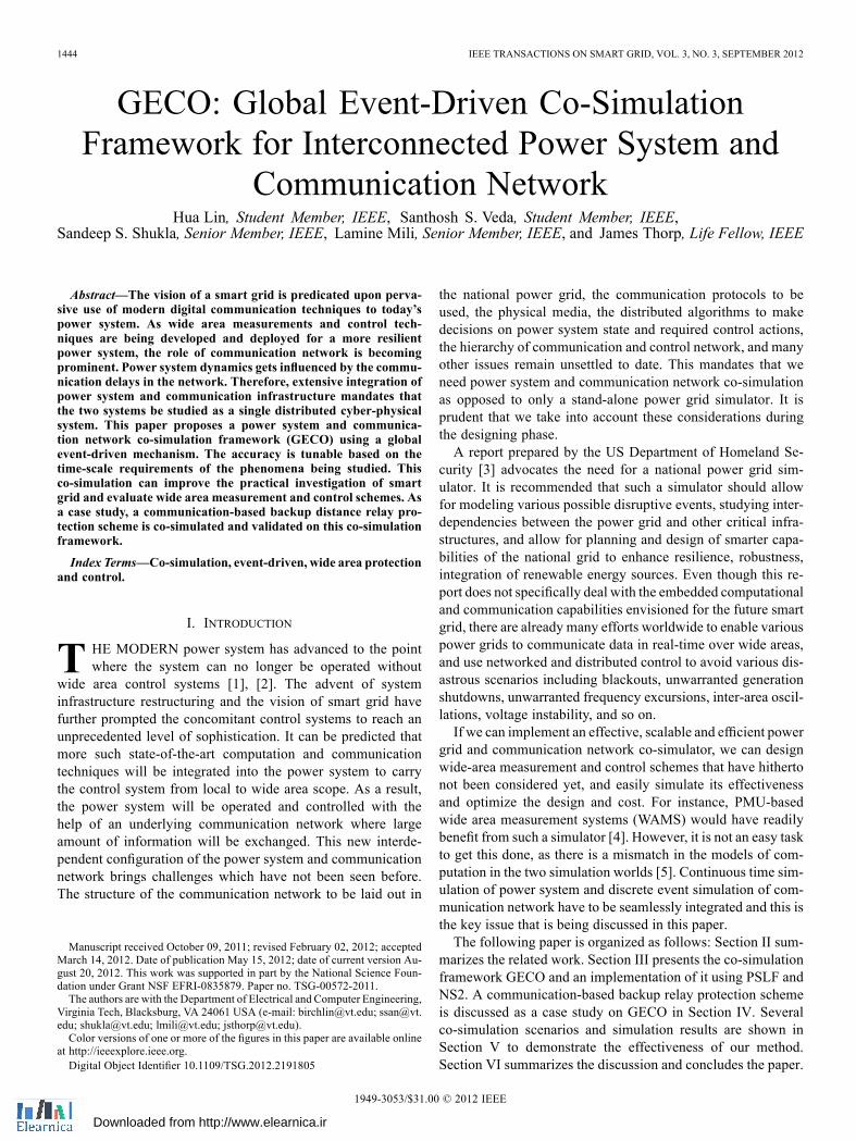
Fig. 10. The steps of relay searching.
C. Relay Search and Decision Making
In both protection schemes, a relay search procedure is re-quired for the agents to determine the responsible relay groupwhen a fault is observed. A relay searching algorithm is imple-mented on a graph abstraction of the power system topology.The step by step instruction of this algorithm is shown in Fig. 10.The power system topology is represented by an undirectedgraph . All the transmission lines are represented byedges and the buses connecting to transmission lines are repre-sented by vertices. The relay in this graph can be representedby an ordered pair which means the relay locatesat the side of bus of the transmission line . The algo-rithm basically consists of two major steps. First, based on therelay who submits the decision request, the algorithm find outthe possible faulted lines. Then for each possible faulted line,the algorithm finds out two primary protection relays and all thebackup relays for this line.As long as the responsible relay group is determined, the pro-
tection decision will be made based on the feedbacks from thisgroup. Since relay protection is a time-critical application, asimple but effective decision making method is applied to theagents:a. Whenever a second relay sees the fault, a trip decision ismade for the relay who submits the request.
b. If and only if none of the relays see a fault, a block deci-sion is made for the relay who submits the request.
V. CO-SIMULATION RESULTS
In this section, the communication-based protection schemesare validated and studied on the co-simulation platform GECO.
A. Simulation Settings
The protection schemes are applied to the New England39-bus system. In this benchmark, there are in total 34 trans-mission lines and consequently 68 distance relay agents are
placed in the system—two for each line. The 10 generators inthe system are cylindrical rotor machines represented by equalmutual inductances on the direct and quadrature axes. Eachgenerator is equipped with an IEEE type 1 excitation systemmodel with added speed multiplier and basic steam turbine andgovernor. The PSLF simulation time step is set as 0.001 sThe relay agents are connected with each other by a commu-
nication infrastructure which is modeled in NS2. This commu-nication infrastructure contains two levels: substation level andwide area level. We assume that Ethernet is adopted for the localarea network (LAN) for each substation. Then at the substationlevel, all the relay agents in the same substation share a 100Mbps Ethernet. For example, there are 5 transmission lines con-nected to bus 16, then 5 distance relay agents should be placedin bus 16 and connected by an Ethernet. In NS2, these relayagents are represented by individual network nodes in the Eth-ernet model. The relay agents can communicate with other relayagents at different substations via a gateway router. On the widearea level, the substations are connected by high speed directcommunication links. These links have the same topology asthe transmission lines. Each communication link is of 1 Gbpsbandwidth and 5 ms communication delay. These parametersstay constant through the simulation. Since the size of messagesexchanged among relay agents are small [10], UDP is selectedas the main transport protocol between them. The network is as-sumed to be dedicated to the protection scheme so that no back-ground traffic is considered at this stage. However its effect canbe easily evaluated in NS2 as long as the detailed traffic modelis available.
B. Validation of Protection Schemes
In the supervisory protection scheme, the master agent isplaced at bus 16 since this bus has the highest connectiondegree. Two different protection scenarios are co-simulatedrespectively:1. There is a real fault but the primary relay fails2. There is no fault but the backup relay has false readingFirst, a real short circuit fault is created at 0.1 second on the
transmission line between bus 4 and bus 14 as shown in Fig. 11.Then the primary relay covering this line at bus 4 is assumed tofail to isolate the fault so that its zone 3 backup protection relayscan take action instead. In this case, the backup relays are bus3 and bus 5 will submit requests to the master agent and waitfor decision. The master agent will collect information from allthe responsible relays to make a decision and send it back tothe backup relays at bus 3 and bus 5. Second, there is no faultplaced in the system. However, the same backup relay at bus 3is assumed to see a fake zone 3 fault due to a false reading asshown in Fig. 12. According to the protection scheme, it willsend a request to the master for decision. However, the deci-sion is expected to be different from the first protection scenario.The same protection scenarios are also tested for the ad-hoc pro-tection scheme. The results are compared with the supervisorycase.The simulation results of these four protection scenarios are
shown in Fig. 13. From Fig. 13(a) we can see that the fault hasbeen removed after the communication between the agents andthe voltage level at bus 3 recovers back to a normal value. This

LIN et al.: GECO: GLOBAL EVENT-DRIVEN CO-SIMULATION FRAMEWORK 1453
Fig. 11. Backup protection for a real fault [38].
Fig. 12. Backup protection for a fake fault [38].
means that after the master agent collects information from theresponsible relays, the situation is determined as a real fault anda trip decision is sent to the backup relays. Traditional backupdistance relays can also protect the system from this fault butthe supervisory protection is faster. As in Fig. 13(a), the faultis removed within 0.1 second. From Fig. 13(b) we can find thefalse-tripping by backup relay is avoided after the communica-tion. The voltage level at bus 3 remains the same. This showsthat after the master agent collects information from the respon-sible relays, the situation is determined as a fake fault and ablock decision is sent to the backup relay with false reading.Traditional backup distance relays, however, will trip the lineand may result in cascading failures due to very limited systemvisibility. Figure Fig. 13(c) and (d) shows the protection resultsfor the ad-hoc protection scheme. It shows that the real fault issuccessfully isolated and the false-tripping is blocked as well.But the total time needed to finish the action is less than the su-pervisory protection scheme.It is very important that the communication time between
agents has to be limited within a certain threshold. The com-munication time for the four protection scenarios is shown inTable II. All of the protection actions can be completed withinthe general Zone 2 time delay of 100 ms and that the ad-hoc
Fig. 13. Voltage magnitude seen by the relay at bus 3: (a) supervisory protec-tion for real fault; (b) supervisory protection for fake fault; (c) adhoc protectionfor real fault; (d) adhoc protection for fake fault.
TABLE IICOMMUNICATION TIME OF THE PROTECTION SCHEMES
protection scheme takes significantly lesser time than the super-visory protection. Moreover, a block decision always requireslonger time than a trip decision which is reasonable consideringthe decision making mechanism we have adopted.
C. Comparison of Different Synchronization Methods
In previous sections, the disadvantages of alternative syn-chronization method have been discussed. Further, the com-munication-based protection scheme is also experimented on aco-simulation platform using the time-stepped synchronizationmethod [13]. The platform tested in this part is not the originalplatform as in [13], but instead a similarly reproduced one. Theprotection scenario in this experiment is the supervisory protec-tion for a real fault. The initial fault time, fault location, masteragent location and the relay agents involved are all the same.This scenario is repeated on the time-stepped synchronizationplatform using different synchronization steps and the resultsare compared with the one on GECO. As a simulation index,the voltage levels at bus 3 among all the simulation results areplotted all together in Fig. 14. From the figure, we can easily tellthe difference among simulations. As the synchronization timestep increases, simulation errors are accumulated and the pro-tection action is delayed accordingly. With this delay in hand,the real system dynamics will be difficult to estimate. In gen-eral, for the time-stepped synchronization method, the larger thetime step is chosen, the more inaccurate results are expected.However, in the extreme case, if the time step is as small as thepower system iteration time step, this method can provide the

1454 IEEE TRANSACTIONS ON SMART GRID, VOL. 3, NO. 3, SEPTEMBER 2012
Fig. 14. Simulation results using different synchronization methods.
same simulation fidelity as the global event-driven co-simula-tion framework. In Fig. 14, the voltage level of time-steppedsynchronization using 0.001 s time step is almost the same asGECO. This similarity further proves the advantage and neces-sity of our co-simulation framework for fully integrated powersystem and communication network.
D. Co-Simulation Scalability
The scalability of the co-simulation platform is another im-portant factor considering the actual power system of interestcan be much larger than this 39-bus benchmark. Since GECOintegrates two individual simulators, the overall co-simulationscalability will be largely determined by the scalability of theindividual simulators themselves and how the integration inter-face is handled. More specifically, in this case, PSLF is able tosimulate a system as large as 60 000 buses and NS2 is able tosimulate a network with at least 20 000 nodes and the simula-tion time is on the order of [39]. Therefore, GECOhas the capacity to model and simulate large national systemslike WECC. On the other hand, the two simulators are inte-grated using a bi-directional interface where system informa-tion is exchanged. As the system scale grows, the amount ofsystem information through this interface will increase accord-ingly. The time needed to complete a co-simulation case mayalso increase depending on the number of interactions betweenthe two simulators.As an example, the same communication-based protection
scheme is implemented on a 127-bus WECC system and theco-simulation speed is compared to the 39-bus case. There are112 transmission lines, 28 generators in this 127-bus system incomparison to 34 lines and 10 generators in the 39-bus system.The co-simulation speeds are shown in Table III. The stop timein both simulators is set as 0.5 second. Two PSLF simulationtime steps: 0.001 second and 0.01 second, are selected for com-parison. Smaller PSLF time step results in more discrete powersystem events and more interactions through the interface be-tween the PSLF and NS2. In Table III, the total simulation timerequired for different settings are measured on a regular PC. Itis clear that co-simulations for larger systems or with smallerpower steps both require longer simulation time. However, thelatter factor contributes significantly more than the former one.The co-simulation results in Table III indicate that the inter-
face between PSLF and NS2 may be a bottleneck for GECO
TABLE IIICOMPARISON OF THE SIMULATION SPEED
as far as larger scale systems are concerned. This is due to thenature that these two individual simulators are not designedfor the purpose of integration with each other. The interfaceis mainly designed to make information exchange and globalevent scheduler feasible rather than to optimize the overallco-simulation speed. However, there are many potential ways toimprove the co-simulation speed since PSLF and NS2 is not theonly solution for GECO. Many other power system and com-munication network simulators can be readily integrated usingGECO framework like PSS/E, InterPSS, OPNET, OMNET++etc. Depending on the simulators, it is possible to parallel theco-simulation or use distributed resources to expedite the simu-lation speed [40], [41]. However it requires great support fromthe simulators and the coordination between simulators can bemuch more complicated. In the case of current implementationof GECO, PSLF is not an open source software. Therefore verylimited change can be made to facilitate the speedup.
VI. CONCLUSION
In this paper a global event-driven co-simulation frame-work GECO is proposed which integrates the simulations ofpower system and communication network. Compared to otherpeople’s related work, our co-simulation framework providesbetter synchronization accuracy and the feasibility of thismethod is proved using formal method. The co-simulationframework is implemented using PSLF and NS2 software. Acommunication-based backup distance relay protection schemeis discussed as a case study on the co-simulation platform. Inthis scheme, the relay agents proactively communicate witheach other to gain better system visibility and make coordinatedprotection decisions. The co-simulation results validate theprotection scheme and the communication time needed is lessthan the threshold. In the end, a comparison between the globalevent-driven method and other synchronization methods isshown. The results present the advantages of our co-simulationframework.
REFERENCES[1] A. G. Phadke and R. M. de Moraes, “The wide world of wide-area
measurement,” IEEE Power Energy Mag., vol. 6, pp. 52–65, 2008.[2] D. Karlsson, M. Hemmingsson, and S. Lindahl, “Wide area system
monitoring and control—Terminology, phenomena, and solution im-plementation strategies,” IEEE Power Energy Mag., vol. 2, pp. 68–76,2004.
[3] “National power grid simulator workshop report,” U.S. Dept. Home-land Security, 2008.
[4] J. De La Ree, V. Centeno, J. S. Thorp, and A. G. Phadke, “Synchro-nized phasor measurement applications in power systems,” IEEETrans. Smart Grid, vol. 1, pp. 20–27, 2010.
[5] S. M. Rinaldi, J. P. Peerenboom, and T. K. Kelly, “Identifying, un-derstanding, and analyzing critical infrastructure interdependencies,”IEEE Control Syst., vol. 21, pp. 11–25, 2001.
LIN et al.: GECO: GLOBAL EVENT-DRIVEN CO-SIMULATION FRAMEWORK 1455
[6] M. C. D’Abreu and G. A. Wainer, “Models for continuous and hy-brid system simulation,” in Proc. 2003 Winter Simul. Conf., vol. 1, pp.641–649.
[7] F. Bouchhima, M. Briere, G. Nicolescu, M. Abid, and E. M.Aboulhamid, “A SystemC/Simulink co-simulation framework forcontinuous/discrete-events simulation,” in Proc. 2006 IEEE Int.Behav. Modeling Simul. Workshop, pp. 1–6.
[8] J. H. Taylor and Z. Jie, “Rigorous hybrid systems simulation with con-tinuous-time discontinuities and discrete-time components,” in Proc.Mediterranean Conf. Control Autom. (MED’07), pp. 1–6.
[9] J. Eker, J. W. Janneck, E. A. Lee, L. Jie, L. Xiaojun, J. Ludvig, S.Neuendorffer, S. Sachs, and X. Yuhong, “Taming heterogeneity—Theptolemy approach,” Proc. IEEE, vol. 91, pp. 127–144, 2003.
[10] A. G. Phadke and J. S. Thorp, “Communication needs for wide areameasurement applications,” in Proc. 2010 5th Int. Conf. Critical In-frastruct. (CRIS), pp. 1–7.
[11] M. Chenine and L. Nordstrom, “Modeling and simulation of wide-areacommunication for centralized PMU-based applications,” IEEE Trans.Power Del., vol. 26, pp. 1372–1380, 2011.
[12] J. W. Stahlhut, T. J. Browne, G. T. Heydt, and V. Vittal, “Latencyviewed as a stochastic process and its impact on wide area powersystem control signals,” IEEE Trans. Power Syst., vol. 23, pp. 84–91,2008.
[13] K. Hopkinson, W. Xiaoru, R. Giovanini, J. Thorp, K. Birman, andD. Coury, “EPOCHS: A platform for agent-based electric power andcommunication simulation built from commercial off-the-shelf com-ponents,” IEEE Trans. Power Syst., vol. 21, pp. 548–558, 2006.
[14] J. Nutaro, P. T. Kuruganti, L. Miller, S. Mullen, and M. Shankar, “In-tegrated hybrid-simulation of electric power and communications sys-tems,” in Proc. IEEE Power Eng. Soc. Gen. Meet. 2007, pp. 1–8.
[15] K. Zhu, M. Chenine, and L. Nordstrom, “ICT architecture impact onwide area monitoring and control systems’ reliability,” IEEE Trans.Power Del., vol. 26, no. 4, pp. 2801–2808, Oct. 2011.
[16] W. Li, A. Monti, M. Luo, and R. A. Dougal, “VPNET: A co-simula-tion framework for analyzing communication channel effects on powersystems,” in Proc. 2011 IEEE Electr. Ship Technol. Symp. (ESTS), pp.143–149.
[17] V. Liberatore and A. Al-Hammouri, “Smart grid communication andco-simulation,” in Proc. 2011 IEEE Energytech, pp. 1–5.
[18] T. Xiaoyang, “The co-simulation extending for wide-area communi-cation networks in power system,” in Proc. 2010 Asia-Pacific PowerEnergy Eng. Conf. (APPEEC), pp. 1–4.
[19] C. M. Davis, J. E. Tate, H. Okhravi, C. Grier, T. J. Overbye, and D.Nicol, “SCADA cyber security testbed development,” in Proc. 38thNorth Amer. Power Symp. (NAPS 2006), pp. 483–488.
[20] M. Mallouhi, Y. Al-Nashif, D. Cox, T. Chadaga, and S. Hariri, “Atestbed for analyzing security of SCADA control systems (TASSCS),”in Proc. 2011 IEEE PES Innov. Smart Grid Technol. (ISGT), pp. 1–7.
[21] A. Ashok, A. Hahn, and G. Manimaran, “Cyber-physical securitytestbed: System architecture and studies,” presented at the CyberSecurity Inf. Intell. Res. (CSIIR) Workshop, Oak Ridge NationalLaboratory (ORNL), Oak Ridge, TN, 2011.
[22] A. Hahn, B. Kregel, M. Govindarasu, J. Fitzpatrick, R. Adnan, S.Sridhar, and M. Higdon, “Development of the PowerCyber SCADAsecurity testbed,” presented at the 6th Annu. Workshop Cyber SecurityInf. Intell. Res., Oak Ridge, TN, 2010.
[23] T. Chiocchio, R. Leonard, Y. Work, R. Fang, M. Steurer, A. Monti, J.Khan, J. Ordonez, M. Sloderbeck, and S. L. Woodruff, “A co-simula-tion approach for real-time transient analysis of electro-thermal systeminteractions on board of future all-electric ships,” presented at the 2007Summer Comput. Simul. Conf., San Diego, CA.
[24] I. Leonard, T. Baldwin, and M. Sloderbeck, “Accelerating the cus-tomer-driven microgrid through real-time digital simulation,” in Proc.IEEE Power Energy Soc. Gen. Meet. (PES’09), 2009, pp. 1–3.
[25] C. Zhang, V. K. Vijapurapu, A. K. Srivastava, N. N. Schulz, J. Bastos,and R. Wierckx, “Hardware-in-the-loop simulation of distance relayusing RTDS,” presented at the 2007 Summer Comput. Simul. Conf.,San Diego, CA.
[26] R. Kuffel, D. Ouellette, and P. Forsyth, “Real time simulation andtesting using IEC 61850,” in Proc. 2010 Proc. Int. Symp. ModernElectr. Power Syst. (MEPS), pp. 1–8.
[27] B. P. Zeigler, Theory of Modeling and Simulation, 2nd ed. NewYork:Academic, 2000.
[28] A. G. Phadke and J. S. Thorp, “Expose hidden failures to prevent cas-cading outages [in power systems],” IEEE Comput. Appl. Power, vol.9, pp. 20–23, 1996.
[29] H. Wang and J. S. Thorp, “Optimal locations for protection systemenhancement: A simulation of cascading outages,” IEEE Trans. PowerDel., vol. 16, pp. 528–533, 2001.
[30] J. De La Ree, Y. Liu, L. Mili, A. G. Phadke, and L. DaSilva, “Cata-strophic failures in power systems: Causes, analyses, and countermea-sures,” Proc. IEEE, vol. 93, pp. 956–964, 2005.
[31] W. R. Lachs, “A new horizon for system protection schemes,” IEEETrans. Power Syst., vol. 18, pp. 334–338, 2003.
[32] S. Song, Y. Zhu, M. Huang, and H. Yu, “Multiagent and WAN basedadaptive coordinated protection system,” in Proc. 2005 IEEE/PESTransm. Distrib. Conf. Exhib. Asia Pacific, 2005, pp. 1–6.
[33] T. Shono, K. Sekiguchi, T. Tanaka, and S. Katayarna, “A remote super-visory system for a power system protection and control unit applyingmobile agent technology,” in Proc. 2002 IEEE/PES Transm. Distrib.Conf. Exhib. Asia Pacific, vol. 1, pp. 148–153.
[34] W. Dong-Qing, M. Shi-Hong, L. Xiang-Ning, L. Pei, W. Ying-Xin,and Y. Dan, “Design of a novel wide-area backup protection system,”in Proc. 2005 IEEE/PES Transm. Distrib. Conf. Exhib. Asia Pacific,pp. 1–6.
[35] X. Tianqi, Y. Xianggen, Y.Dahai, L. Yan, andW.Yangguang, “A novelcommunication network for three-level wide area protection system,”in Proc. 2008 IEEE Power Energy Soc. Gen. Meet.—Convers. Del.Electr. Energy 21st Century, pp. 1–8.
[36] M. M. Eissa, M. E. Masoud, and M. M. M. Elanwar, “A novel backup wide area protection technique for power transmission grids usingphasor measurement unit,” IEEE Trans. Power Del., vol. 25, pp.270–278, 2010.
[37] R. Giovanini, K. Hopkinson, D. V. Coury, and J. S. Thorp, “A primaryand backup cooperative protection system based on wide area agents,”IEEE Trans. Power Del., vol. 21, pp. 1222–1230, 2006.
[38] I. Hiskens, “Significance of load modeling in power system dynamics,”presented at the Symp. Specialists Electr. Oper. Expansion Plan., 2006.
[39] S. Bak, “Large-scale network simulation scalability and anFPGA-based network simulator,” Univ. Illinois Tech. Rep. [On-line]. Available: http://hdl.handle.net/2142/30815, 2012
[40] S. Kristiansen and T. Plagemann, “Ns-2 distributed clients emulation:Accuracy and scalability,” presented at the 2nd Int. Conf. Simul. ToolsTech., Rome, Italy, 2009.
[41] G. Carl, “Towards large-scale testing of policy-based routing via pathalgebraic and scaled-down topological modeling,” D.Phil. dissertation,Dept. Electr. Eng., Pennsylvania State University, State College, PA,2008.
[42] L. Hua, S. Sambamoorthy, S. Shukla, J. Thorp, and L. Mili, “Powersystem and communication network co-simulation for smart grid appli-cations,” in Proc. 2011 IEEE PES Innov. Smart Grid Technol. (ISGT),pp. 1–6.
[43] L. Hua, S. Sambamoorthy, S. Shukla, J. Thorp, and L. Mili, “Ad-hocvs. supervisory wide area backup relay protection validated on power/network co-simulation platform,” presented at the 17th Power Syst.Comput. Conf. (PSCC), Stockholm, Sweden, 2011.
[44] S. Garlapati, L. Hua, S. Sambamoorthy, S. K. Shukla, and J. Thorp,“Agent based supervision of zone 3 relays to prevent hidden failurebased tripping,” inProc. 2010 1st IEEE Int. Conf. Smart Grid Commun.(SmartGridComm), pp. 256–261.
[45] G. N. Ericsson, “On requirements specifications for a power systemcommunications system,” IEEE Trans. Power Del., vol. 20, pp.1357–1362, 2005.
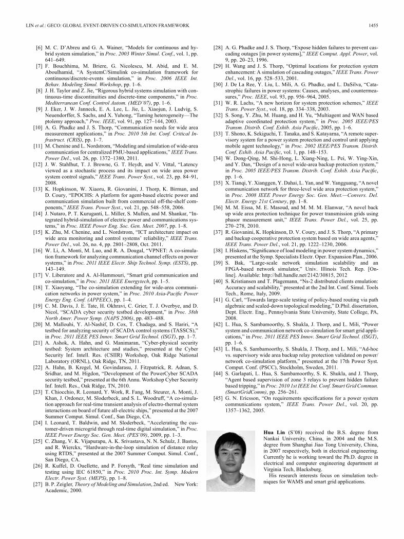
Hua Lin (S’08) received the B.S. degree fromNankai University, China, in 2004 and the M.S.degree from Shanghai Jiao Tong University, China,in 2007 respectively, both in electrical engineering.Currently he is working toward the Ph.D. degree inelectrical and computer engineering department atVirginia Tech, Blacksburg.His research interests focus on simulation tech-
niques for WAMS and smart grid applications.

1456 IEEE TRANSACTIONS ON SMART GRID, VOL. 3, NO. 3, SEPTEMBER 2012
Santosh S. Veda (S’07) received the B.S. degreein electrical and electronics engineering from AnnaUniversity, Chennai, India, in 2008 and the M.S.degree in electrical engineering from Virginia Tech,Blacksburg in 2011. He is currently working towardthe Ph.D. degree in the Electrical and ComputerEngineering Department at Virginia Tech.His research interests include power system sta-
bility analysis, modeling and simulation, and widearea monitoring protection and control (WAMPAC).Mr. Veda was conferred Vocational Excellence
Award by the Rotary Club of Coimbatore in 2008.
Sandeep K. Shukla (SM’03) received the Ph.D. de-gree from the State University of NewYork at Albanyin 1997.He is an Associate Professor in the Department
of Electrical and Computer Engineering at VirginiaPolytechnic and State University, Blacksburg. He isalso the director of the Center for Embedded Systemsfor Critical Applications (CESCA).Prof. Shukla is Associate Editor of IEEE
TRANSACTIONS ON COMPUTERS and IEEE Em-bedded Systems Letters. He was associate editors
for IEEE Design & Test of Computers (2003–2011), and IEEE TRANSACTIONSON INDUSTRIAL INFORMATICS (2005–2006). He was awarded the PECASE in2004, Virginia Tech Engineering Faculty Fellow award in 2005, SUNY AlbanyDistinguished Alumni Award in 2007, and Humboldt Foundation’s Besselaward in 2008. He is an IEEE Computer Society Distinguished Visitor, and anACM Distinguished Speaker.
Lamine Mili (SM’90) received an Electrical Engi-neering Diploma from the Swiss Federal Institute ofTechnology, Lausanne, in 1976, and the Ph.D. degreefrom the University of Liège, Belgium, in 1987.He is a Professor of Electrical and Computer
Engineering at Virginia Tech, Blacksburg. He hasfive years of industrial experience with the Tunisianelectric utility, STEG. At STEG, he worked in theplanning department from 1976 to 1979 and then atthe Test and Meter Laboratory from 1979 till 1981.He was a Visiting Professor at the Swiss Federal
Institute of Technology, Lausanne, the Grenoble Institute of Technology and theÉcole Supérieure d’Électricité in France, the École Polytechnique de Tunisie, inTunisia, and did consulting work for the French Power Transmission companyRTE. His research has focused on power system planning for enhanced re-siliency and sustainability, risk management of complex systems to catastrophicfailures, robust estimation and control, nonlinear dynamics, and bifurcationtheory. He is the co-founder and co-editor of the International Journal ofCritical Infrastructures, http://www.inderscience.com/browse/index.php?jour-nalCODE=ijcis.
James Thorp (F’89–LF’03) received the Ph.D. de-gree from Cornell University, Ithaca, NY, in 1962.He is an Emeritus Professor in the Department
of Electrical and Computer Engineering at Vir-ginia Polytechnic Institute and State University,Blacksburg.Prof. Thorp was an Associate Editor for IEEE
TRANSACTIONS ON CIRCUITS AND SYSTEMS from1985 to 1987. He is a member of the NationalAcademy of Engineering, a member of the IEEEPower System Relaying Committee, CIGRE, Eta
Kappa Nu, Tau Beta Pi, and Sigma Xi. He is also co-recipient of the BenjaminFranklin Medal in 2008.