14’ wide & 28’ wide at/ut/uss induced draft...
TRANSCRIPT

1
AT/UT/USS Cooling Towers
Cert no. BV-COC-080211
Bulletin 144X
Rigging andAssembly Instructions
14’ WIDE & 28’ WIDE AT/UT/USSINDUCED DRAFT COOLING TOWERS
EVAPCO, Inc.North American HeadquartersP.O. Box 1300Westminster, MD 21158 USAPhone: 410-756-2600Fax: 410-756-6450E-mail: [email protected]
EVAPCO East5151 Allendale LaneTaneytown, MD 21787 USAPhone: 410-756-2600Fax: 410-756-6450E-mail: [email protected]
EVAPCO Midwest1723 York RoadGreenup, IL 62428 USAPhone: 217-923-3431Fax: 217-923-3300E-mail: [email protected]
EVAPCO West1900 West Almond AvenueMadera, CA 93637 USAPhone: 559-673-2207Fax: 559-673-2378E-mail: [email protected]
EVAPCO Iowa925 Quality DriveLake View, IA 51450 USAPhone: 712-657-3223Fax: 712-657-3226
EVAPCO IowaSales & Engineering1234 Brady BoulevardOwatonna, MN 55060 USAPhone: 507-446-8005Fax: 507-446-8239E-mail: [email protected]
Refrigeration Valves & Systems CorporationA wholly owned subsidiary of EVAPCO, Inc.1520 Crosswind Dr.Bryan, TX 77808 USAPhone: 979-778-0095Fax: 979-778-0030E-mail: [email protected]
McCormack Coil Company, Inc.A wholly owned subsidiary of EVAPCO, Inc.P.O. Box 17276333 S.W. Lakeview BoulevardLake Oswego, OR 97035 USAPhone: 503-639-2137Fax: 503-639-1800E-mail: [email protected]
EvapTech, Inc.A wholly owned subsidiary of EVAPCO, Inc.8331 Nieman RoadLenexa, KS 66214 USAPhone: 913-322-5165Fax: 913-322-5166E-mail: [email protected]
Tower Components, Inc.A wholly owned subsidiary of EVAPCO, Inc.5960 US HWY 64ERamseur, NC 27316Phone: 336-824-2102Fax: 336-824-2190E-mail: [email protected]
EVAPCO Newton701 East Jourdan StreetNewton, IL 62448Phone: 618-783-3433Fax: 618-783-3499E-mail: [email protected]
EVAPCO Europe, N.V.European HeadquartersIndustrieterrein Oost 40103700 Tongeren, BelgiumPhone: (32) 12-395029Fax: (32) 12-238527E-mail: [email protected]
EVAPCO Europe, S.r.l.Via Ciro Menotti 10I-20017 Passirana di RhoMilan, ItalyPhone: (39) 02-939-9041Fax: (39) 02-935-00840E-mail: [email protected]
EVAPCO Europe, S.r.l.Via Dosso 223020 Piateda Sondrio, Italy
EVAPCO Europe, GmbHBovert 22D-40670 Meerbusch, GermanyPhone: (49) 2159-69560Fax: (49) 2159-695611E-mail: [email protected]
EVAPCO S.A. (Pty.) Ltd.A licensed manufacturer of Evapco, Inc.18 Quality RoadIsando 1600Republic of South AfricaPhone: (27) 11-392-6630Fax: (27) 11-392-6615E-mail: [email protected]
Tiba Engineering Industries Co.A licensed manufacturer of Evapco, Inc.5 Al Nasr Road StreetNasr CityCairo, EgyptPhone: (20)2-290-7483/(20)2-291-3610Fax: (20)2-404-4667/(20)2-290-0892E-mail: [email protected]
EVAPCO ChinaAsia/Pacific Headquarters1159 Luoning Rd. Baoshan Industrial ZoneShanghai, P. R. ChinaPost Code: 200949Phone: (86) 21-6687-7786Fax: (86) 21-6687-7008E-mail: [email protected]
EVAPCO (Shanghai) Refrigeration Equipment Co., Ltd1159 Luoning Rd. Baoshan Industrial ZoneShanghai, P. R. ChinaPost Code: 200949Phone: (86) 21-6687-7786Fax: (86) 21-6687-7008E-mail: [email protected]
Aqua-Cool Towers (Pty.) Ltd.A licensed manufacturer of Evapco, Inc.34-42 Melbourne St.P.O. Box 436Riverstone, N.S.W. Australia 2765Phone: (61) 29-627-3322Fax: (61) 29-627-1715E-mail: [email protected]
EvapTech Asia Pacific sdn. BhdA wholly owned subsidiary of EvapTech, Inc.IOI Business Park, 2/F Unit 21 Persiaran Puchong Jaya Selatan Bandar Puchong Jaya,47170 Puchong Selangor, MalaysiaPhone: +(60-3) 8070 7255Fax: +(60-3) 8070 5731E-mail: [email protected]
EVAPCO North America
EVAPCO, Inc. - World Headquarters & Research/Development Center
EVAPCO Europe EVAPCO Asia/Pacific
EVAPCO, Inc. P.O. Box 1300 Westminster, MD 21158 USAPhone: 410-756-2600 Fax: 410-756-6450 E-mail: [email protected]
2
AT/UT/USS Cooling Towers
IntroductionThank you for purchasing your EVAPCO cooling tower. This manual will provide instructions for installation of the cooling tower. If you have purchased a model UT cooling tower or AT or USS with the Super Low Sound Fan option, please be sure to pay attention to the proper rigging instructions for that special option enclosed herein. If any questions arise during the installation, please contact your local EVAPCO representative or us directly at our Global Headquarters location.
International Building Code ProvisionsThe International Building Code (IBC) is a comprehensive set of regulations addressing the structural design and installation requirements for building systems – including HVAC and industrial refrigeration equipment. As of June 2008, all 50 states plus Washington D.C. have adopted the International Building Code. The code provisions require that evaporative cooling equipment and all other components permanently installed on a structure must meet the same seismic design criteria as the building. The AT/UT/USS Series of Open Cooling Towers are IBC 2006 compliant up to 1g with standard construction and up to 5.12g with additional structural modifications.
All items attached to the Evapco AT/UT/USS cooling tower must be independently reviewed and isolated to meet applicable wind and seismic loads. This includes piping, ductwork, conduit, and electrical connections. These items must be flexibly attached to the Evapco unit so as not to transmit additional loads to the equipment as a result of seismic or wind forces.
Method of ShipmentAll 14’ and 28’ wide units are shipped with the top section(s) separate from the bottom section(s). These sections have mating flanges and will join together in a waterproof joint when sealed and bolted together as described in the following instructions. Miscellaneous items, such as sealer, screws, drip channels, splash guards and any other required materials, are packaged and placed inside the pan for shipment.
StorageDo not place tarps or other coverings over the top of the units if the units are to be stored before installation. Excessive heat can build up if the units are covered, causing possible damage to the PVC eliminators, PVC louvers, or PVC fill. For extended storage beyond six months rotate the fan and fan motor shaft(s) monthly. The fan shaft bearings should also be purged and regreased prior to start-up if it has been stored.
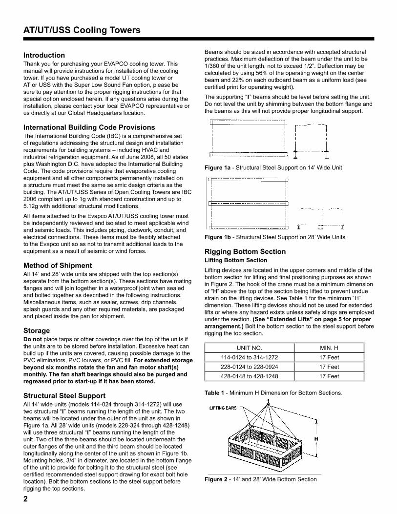
Structural Steel SupportAll 14’ wide units (models 114-024 through 314-1272) will use two structural “I” beams running the length of the unit. The two beams will be located under the outer of the unit as shown in Figure 1a. All 28’ wide units (models 228-324 through 428-1248) will use three structural “I” beams running the length of the unit. Two of the three beams should be located underneath the outer flanges of the unit and the third beam should be located longitudinally along the center of the unit as shown in Figure 1b. Mounting holes, 3/4” in diameter, are located in the bottom flange of the unit to provide for bolting it to the structural steel (see certified recommended steel support drawing for exact bolt hole location). Bolt the bottom sections to the steel support before rigging the top sections.
Beams should be sized in accordance with accepted structural practices. Maximum deflection of the beam under the unit to be 1/360 of the unit length, not to exceed 1/2”. Deflection may be calculated by using 56% of the operating weight on the center beam and 22% on each outboard beam as a uniform load (see certified print for operating weight).
The supporting “I” beams should be level before setting the unit. Do not level the unit by shimming between the bottom flange and the beams as this will not provide proper longitudinal support.
Figure 1a - Structural Steel Support on 14’ Wide Unit
Figure 1b - Structural Steel Support on 28’ Wide Units
Rigging Bottom SectionLifting Bottom SectionLifting devices are located in the upper corners and middle of the bottom section for lifting and final positioning purposes as shown in Figure 2. The hook of the crane must be a minimum dimension of “H” above the top of the section being lifted to prevent undue strain on the lifting devices. See Table 1 for the minimum “H” dimension. These lifting devices should not be used for extended lifts or where any hazard exists unless safety slings are employed under the section. (See “Extended Lifts” on page 5 for proper arrangement.) Bolt the bottom section to the steel support before rigging the top section.
UNIT NO. MIN. H114-0124 to 314-1272 17 Feet228-0124 to 228-0924 17 Feet428-0148 to 428-1248 17 Feet
Table 1 - Minimum H Dimension for Bottom Sections.
H
Figure 2 - 14’ and 28’ Wide Bottom Section
3
AT/UT/USS Cooling Towers
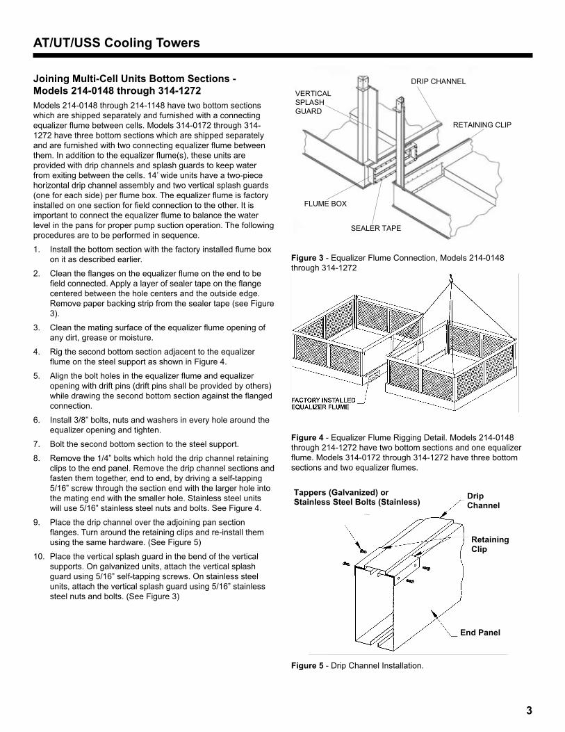
Joining Multi-Cell Units Bottom Sections - Models 214-0148 through 314-1272Models 214-0148 through 214-1148 have two bottom sections which are shipped separately and furnished with a connecting equalizer flume between cells. Models 314-0172 through 314-1272 have three bottom sections which are shipped separately and are furnished with two connecting equalizer flume between them. In addition to the equalizer flume(s), these units are provided with drip channels and splash guards to keep water from exiting between the cells. 14’ wide units have a two-piece horizontal drip channel assembly and two vertical splash guards (one for each side) per flume box. The equalizer flume is factory installed on one section for field connection to the other. It is important to connect the equalizer flume to balance the water level in the pans for proper pump suction operation. The following procedures are to be performed in sequence.
Install the bottom section with the factory installed flume box 1. on it as described earlier.
Clean the flanges on the equalizer flume on the end to be 2. field connected. Apply a layer of sealer tape on the flange centered between the hole centers and the outside edge. Remove paper backing strip from the sealer tape (see Figure 3).
Clean the mating surface of the equalizer flume opening of 3. any dirt, grease or moisture.
Rig the second bottom section adjacent to the equalizer 4. flume on the steel support as shown in Figure 4.
Align the bolt holes in the equalizer flume and equalizer 5. opening with drift pins (drift pins shall be provided by others) while drawing the second bottom section against the flanged connection.
Install 3/8” bolts, nuts and washers in every hole around the 6. equalizer opening and tighten.
Bolt the second bottom section to the steel support.7.
Remove the 1/4” bolts which hold the drip channel retaining 8. clips to the end panel. Remove the drip channel sections and fasten them together, end to end, by driving a self-tapping 5/16” screw through the section end with the larger hole into the mating end with the smaller hole. Stainless steel units will use 5/16” stainless steel nuts and bolts. See Figure 4.
Place the drip channel over the adjoining pan section 9. flanges. Turn around the retaining clips and re-install them using the same hardware. (See Figure 5)
Place the vertical splash guard in the bend of the vertical 10. supports. On galvanized units, attach the vertical splash guard using 5/16” self-tapping screws. On stainless steel units, attach the vertical splash guard using 5/16” stainless steel nuts and bolts. (See Figure 3)
DRIP CHANNEL
RETAINING CLIP
VERTICAL SPLASH GUARD
FLUME BOX
SEALER TAPE
Figure 3 - Equalizer Flume Connection, Models 214-0148 through 314-1272
Figure 4 - Equalizer Flume Rigging Detail. Models 214-0148 through 214-1272 have two bottom sections and one equalizer flume. Models 314-0172 through 314-1272 have three bottom sections and two equalizer flumes.
Tappers (Galvanized) orStainless Steel Bolts (Stainless)
DripChannel
RetainingClip
End Panel
Figure 5 - Drip Channel Installation.
4
AT/UT/USS Cooling Towers
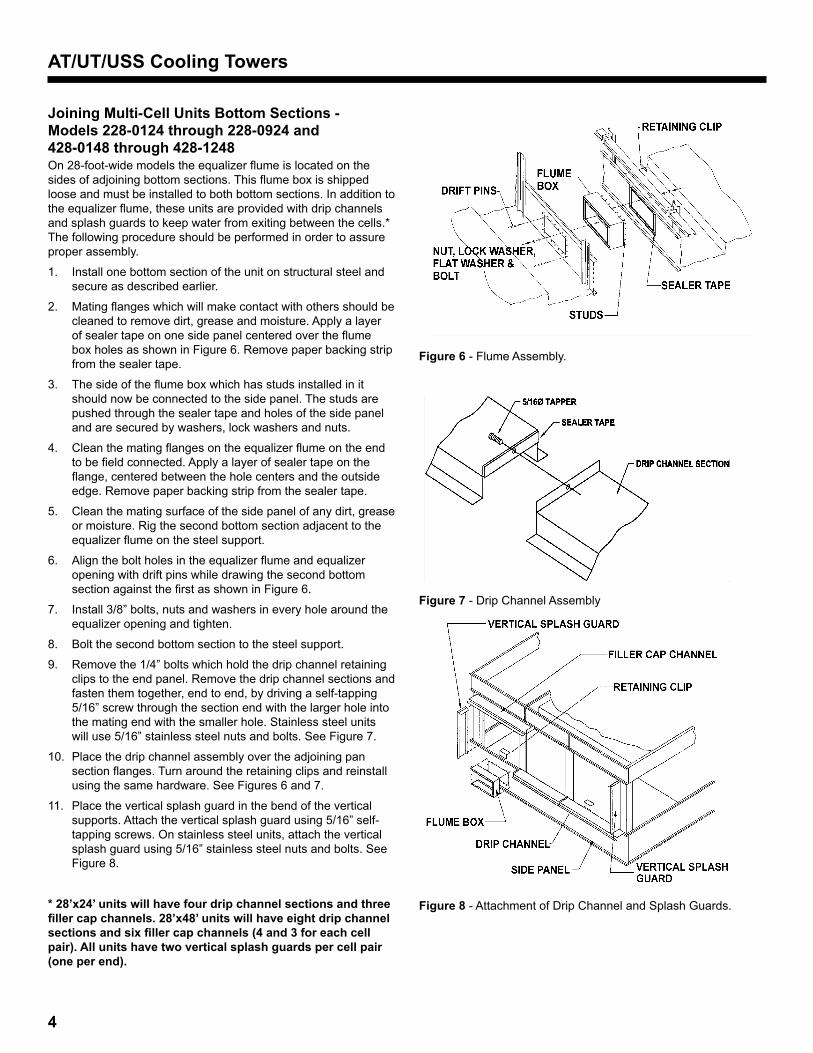
Joining Multi-Cell Units Bottom Sections - Models 228-0124 through 228-0924 and 428-0148 through 428-1248On 28-foot-wide models the equalizer flume is located on the sides of adjoining bottom sections. This flume box is shipped loose and must be installed to both bottom sections. In addition to the equalizer flume, these units are provided with drip channels and splash guards to keep water from exiting between the cells.* The following procedure should be performed in order to assure proper assembly.
Install one bottom section of the unit on structural steel and 1. secure as described earlier.
Mating flanges which will make contact with others should be 2. cleaned to remove dirt, grease and moisture. Apply a layer of sealer tape on one side panel centered over the flume box holes as shown in Figure 6. Remove paper backing strip from the sealer tape.
The side of the flume box which has studs installed in it 3. should now be connected to the side panel. The studs are pushed through the sealer tape and holes of the side panel and are secured by washers, lock washers and nuts.
Clean the mating flanges on the equalizer flume on the end 4. to be field connected. Apply a layer of sealer tape on the flange, centered between the hole centers and the outside edge. Remove paper backing strip from the sealer tape.
Clean the mating surface of the side panel of any dirt, grease 5. or moisture. Rig the second bottom section adjacent to the equalizer flume on the steel support.
Align the bolt holes in the equalizer flume and equalizer 6. opening with drift pins while drawing the second bottom section against the first as shown in Figure 6.
Install 3/8” bolts, nuts and washers in every hole around the 7. equalizer opening and tighten.
Bolt the second bottom section to the steel support.8.
Remove the 1/4” bolts which hold the drip channel retaining 9. clips to the end panel. Remove the drip channel sections and fasten them together, end to end, by driving a self-tapping 5/16” screw through the section end with the larger hole into the mating end with the smaller hole. Stainless steel units will use 5/16” stainless steel nuts and bolts. See Figure 7.
Place the drip channel assembly over the adjoining pan 10. section flanges. Turn around the retaining clips and reinstall using the same hardware. See Figures 6 and 7.
Place the vertical splash guard in the bend of the vertical 11. supports. Attach the vertical splash guard using 5/16” self-tapping screws. On stainless steel units, attach the vertical splash guard using 5/16” stainless steel nuts and bolts. See Figure 8.
* 28’x24’ units will have four drip channel sections and three filler cap channels. 28’x48’ units will have eight drip channel sections and six filler cap channels (4 and 3 for each cell pair). All units have two vertical splash guards per cell pair (one per end).
Figure 6 - Flume Assembly.
Figure 7 - Drip Channel Assembly
Figure 8 - Attachment of Drip Channel and Splash Guards.

5
AT/UT/USS Cooling Towers
Optional Equalizer Blank-Off Plate For All Multi-Cell UnitsAn accessory is available to isolate the bottom sections for individual cell operation, periodic cleaning or maintenance. This optional equalizer blank-off plate is factory installed on the equalizer flume and secured by wing nuts. See Figure 9.
For units not requiring the blank-off plate under normal operating conditions, remove the wing nuts, washers, plate and gasket. Reinstall washers and wing nuts for proper leakfree operation of the flume.
Figure 9 - Optional Blank-Off Plate on the Equalizer Flume.
Application of Sealer TapeOnce the bottom section has been set on the supporting steel and bolted in place, the top flanges should be wiped down to remove any dirt or moisture. Sealer Tape should be placed over the mounting hole centerline on the side flanges. Apply two strips of sealer tape, one partially overlapping the other, on the end flanges.
The sealer tape should overlap on the corners as shown in Figure 10. Do not splice the sealer tape along the end flanges and preferably not on the side flanges if it can be avoided. Always remove the paper backing from the sealer tape.
2 OVERLAPPING LAYERS OF SEALER TAPEON THE ENDS
END
SIDE
1 LAYER OF SEALER TAPE CENTEREDOVER THE MOUNTING HOLES
Figure 10 - Sealer Tape on flange of Bottom Section.
Models 428-0148 through 428-1248 have four top sections. In these cases, sealer tape must be applied to internal flanges as shown in Figure 11.
TAPE OVER
SEALER TAPE
OVERLAP SEALER TAPE
Figure 11 - Sealer Tape Detail for Center Joint of Units with four Top Sections.
Rigging Top Section“U” bolts are provided in the four corners of the top section for lifting and final positioning (See Figure 12). The hook of the crane must be a minimum dimension “H” above the top section being lifted to prevent undue strain on the “U” bolts. See Table 2 for the minimum “H” dimension.
UNIT NO. Standard Fan
Super Low Sound Fan
114-0124 to 314-1272 17 Feet 18 Feet228-0124 to 228-0924 17 Feet 18 Feet428-0148 to 428-1248 17 Feet 18 Feet
Table 2 -Minimum H Dimension for Top Sections.
Figure 12 - Top Section
6
AT/UT/USS Cooling Towers
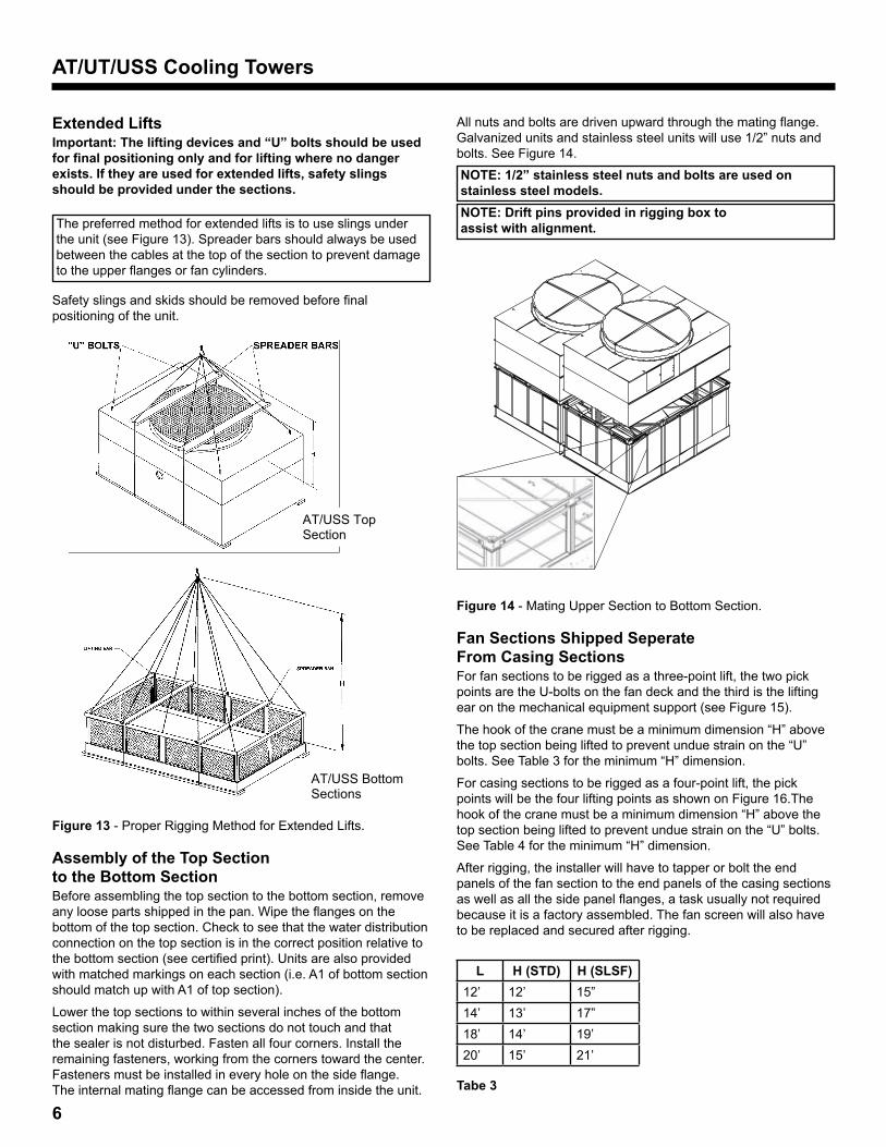
Extended LiftsImportant: The lifting devices and “U” bolts should be used for final positioning only and for lifting where no danger exists. If they are used for extended lifts, safety slings should be provided under the sections.
The preferred method for extended lifts is to use slings under the unit (see Figure 13). Spreader bars should always be used between the cables at the top of the section to prevent damage to the upper flanges or fan cylinders.
Safety slings and skids should be removed before final positioning of the unit.
AT/USS Top Section
AT/USS Bottom Sections
Figure 13 - Proper Rigging Method for Extended Lifts.
Assembly of the Top Section to the Bottom SectionBefore assembling the top section to the bottom section, remove any loose parts shipped in the pan. Wipe the flanges on the bottom of the top section. Check to see that the water distribution connection on the top section is in the correct position relative to the bottom section (see certified print). Units are also provided with matched markings on each section (i.e. A1 of bottom section should match up with A1 of top section).
Lower the top sections to within several inches of the bottom section making sure the two sections do not touch and that the sealer is not disturbed. Fasten all four corners. Install the remaining fasteners, working from the corners toward the center. Fasteners must be installed in every hole on the side flange. The internal mating flange can be accessed from inside the unit.
All nuts and bolts are driven upward through the mating flange. Galvanized units and stainless steel units will use 1/2” nuts and bolts. See Figure 14.NOTE: 1/2” stainless steel nuts and bolts are used on stainless steel models. NOTE: Drift pins provided in rigging box to assist with alignment.
Figure 14 - Mating Upper Section to Bottom Section.
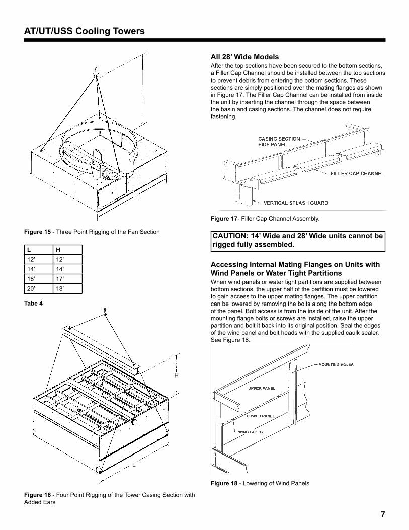
Fan Sections Shipped Seperate From Casing Sections For fan sections to be rigged as a three-point lift, the two pick points are the U-bolts on the fan deck and the third is the lifting ear on the mechanical equipment support (see Figure 15).
The hook of the crane must be a minimum dimension “H” above the top section being lifted to prevent undue strain on the “U” bolts. See Table 3 for the minimum “H” dimension.
For casing sections to be rigged as a four-point lift, the pick points will be the four lifting points as shown on Figure 16.The hook of the crane must be a minimum dimension “H” above the top section being lifted to prevent undue strain on the “U” bolts. See Table 4 for the minimum “H” dimension.
After rigging, the installer will have to tapper or bolt the end panels of the fan section to the end panels of the casing sections as well as all the side panel flanges, a task usually not required because it is a factory assembled. The fan screen will also have to be replaced and secured after rigging.
L H (STD) H (SLSF)12’ 12’ 15”14’ 13’ 17”18’ 14’ 19’20’ 15’ 21’
Tabe 3
7
AT/UT/USS Cooling Towers
Figure 15 - Three Point Rigging of the Fan Section
L H 12’ 12’14’ 14’18’ 17’20’ 18’
Tabe 4
Figure 16 - Four Point Rigging of the Tower Casing Section with Added Ears
All 28’ Wide ModelsAfter the top sections have been secured to the bottom sections, a Filler Cap Channel should be installed between the top sections to prevent debris from entering the bottom sections. These sections are simply positioned over the mating flanges as shown in Figure 17. The Filler Cap Channel can be installed from inside the unit by inserting the channel through the space between the basin and casing sections. The channel does not require fastening.
Figure 17- Filler Cap Channel Assembly.
CAUTION: 14’ Wide and 28’ Wide units cannot be rigged fully assembled.
Accessing Internal Mating Flanges on Units with Wind Panels or Water Tight PartitionsWhen wind panels or water tight partitions are supplied between bottom sections, the upper half of the partition must be lowered to gain access to the upper mating flanges. The upper partition can be lowered by removing the bolts along the bottom edge of the panel. Bolt access is from the inside of the unit. After the mounting flange bolts or screws are installed, raise the upper partition and bolt it back into its original position. Seal the edges of the wind panel and bolt heads with the supplied caulk sealer. See Figure 18.
Figure 18 - Lowering of Wind Panels
H
L
8
AT/UT/USS Cooling Towers
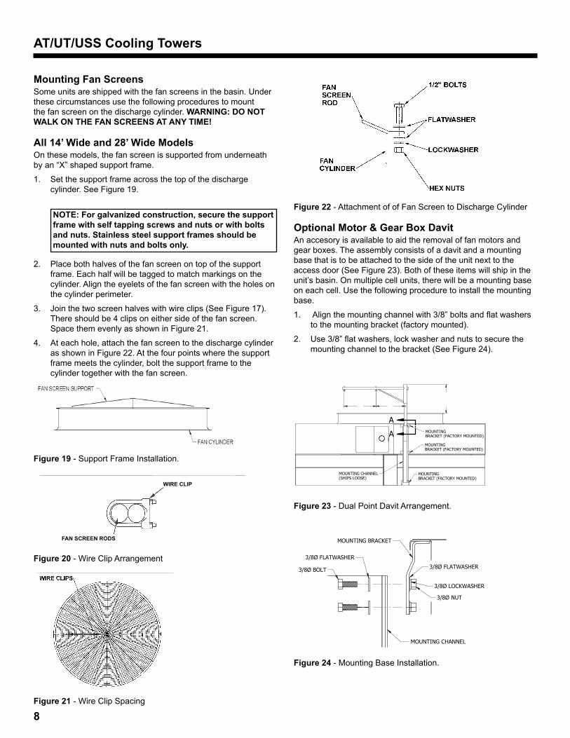
Mounting Fan ScreensSome units are shipped with the fan screens in the basin. Under these circumstances use the following procedures to mount the fan screen on the discharge cylinder. WARNING: DO NOT WALK ON THE FAN SCREENS AT ANY TIME!
All 14’ Wide and 28’ Wide ModelsOn these models, the fan screen is supported from underneath by an “X” shaped support frame.
Set the support frame across the top of the discharge 1. cylinder. See Figure 19.
NOTE: For galvanized construction, secure the support frame with self tapping screws and nuts or with bolts and nuts. Stainless steel support frames should be mounted with nuts and bolts only.
Place both halves of the fan screen on top of the support 2. frame. Each half will be tagged to match markings on the cylinder. Align the eyelets of the fan screen with the holes on the cylinder perimeter.
Join the two screen halves with wire clips (See Figure 17). 3. There should be 4 clips on either side of the fan screen. Space them evenly as shown in Figure 21.
At each hole, attach the fan screen to the discharge cylinder 4. as shown in Figure 22. At the four points where the support frame meets the cylinder, bolt the support frame to the cylinder together with the fan screen.
Figure 19 - Support Frame Installation.
FAN SCREEN RODS
WIRE CLIP
Figure 20 - Wire Clip Arrangement
Figure 21 - Wire Clip Spacing
Figure 22 - Attachment of of Fan Screen to Discharge Cylinder
Optional Motor & Gear Box DavitAn accesory is available to aid the removal of fan motors and gear boxes. The assembly consists of a davit and a mounting base that is to be attached to the side of the unit next to the access door (See Figure 23). Both of these items will ship in the unit’s basin. On multiple cell units, there will be a mounting base on each cell. Use the following procedure to install the mounting base.
Align the mounting channel with 3/8” bolts and flat washers 1. to the mounting bracket (factory mounted).
Use 3/8” flat washers, lock washer and nuts to secure the 2. mounting channel to the bracket (See Figure 24).
NOTES:
REMOVABLE DAVIT
M = MOTOR A.
DAVIT IS DESIGNED FOR RAISING OR LOWERING EVAPCOFAN MOTORS OR FANS AND GEARS AS UNIT ISEQUIPPED. DO NOT USE FOR ANY OTHER PURPOSE.
B.
DAVIT IS DESIGNED TO PIVOT FREELY AND CAN BEREMOVED FROM ITS MOUNTING BASE FOR STORAGE.
C.
DIMENSIONS LISTED AS FOLLOWS: ENGLISH [METRIC] IN [mm]
D. MDAIBFTM-DA
MOUNTING BRACKET
MOUNTING CHANNEL
3/8Ø BOLT
3/8Ø FLATWASHER
3/8Ø FLATWASHER
3/8Ø NUT
3/8Ø LOCKWASHER
ASSEMBLY ARRANGEMENT(TYPICAL)
SECTION A-A
MOUNTINGBRACKET (FACTORY MOUNTED)
MOUNTINGBRACKET (FACTORY MOUNTED)
MOUNTINGBRACKET (FACTORY MOUNTED)
MOUNTING CHANNEL(SHIPS LOOSE)
A
A
FOR STD AND UNITS WITH PLATFORM
M
Figure 23 - Dual Point Davit Arrangement.
NOTES:
REMOVABLE DAVIT
M = MOTOR A.
DAVIT IS DESIGNED FOR RAISING OR LOWERING EVAPCOFAN MOTORS OR FANS AND GEARS AS UNIT ISEQUIPPED. DO NOT USE FOR ANY OTHER PURPOSE.
B.
DAVIT IS DESIGNED TO PIVOT FREELY AND CAN BEREMOVED FROM ITS MOUNTING BASE FOR STORAGE.
C.
DIMENSIONS LISTED AS FOLLOWS: ENGLISH [METRIC] IN [mm]
D. MDAIBFTM-DA
43 1/2 [1105] STAND
MOUNTING BRACKET
MOUNTING CHANNEL
3/8Ø BOLT
3/8Ø FLATWASHER
3/8Ø FLATWASHER
3/8Ø NUT
3/8Ø LOCKWASHER
ASSEMBLY ARRANGEMENT(TYPICAL)
SECTION A-A
MOUNTINGBRACKET (FACTORY MOUNTED)
MOUNTINGBRACKET (FACTORY MOUNTED)
MOUNTINGBRACKET (FACTORY MOUNTED)
MOUNTING CHANNEL(SHIPS LOOSE)
A
A
4448
FOR STD AND UNITS WITH PLATFORM
500LBMAX
1250LBMAX
M
14 X 24/48/72 AT2/AT3 BELT DRIVE
Figure 24 - Mounting Base Installation.

9
AT/UT/USS Cooling Towers
Assembly of Sloped LaddersWhen sloped ladders are supplied with a unit, they are shipped in the basin of the unit. One sloped ladder will be provided for each cell. Assembly is identical for each cell. Sloped ladders are attached at a minimum of three points. Taller units will be attached at four points. At each point of attachment, the ladder will be fitted with a ladder bracket assembly. The ladder bracket assembly looks like a metal box and is shown in detail (component #4) in Figure 25 below. The upper two assembly brackets will be rigidly mounted to the ladder and are not adjustable. These two bracket define the slope of the ladder. The lower brackets are adjustable.
Figure 25 - Detail of Ladder, Ladder Bracket Assembly and Mounting Channel
To install the ladder assembly, follow the steps outlined below which refer to Figure 26:
Remove the ladder bracket mounting bolts (1) from the 1. ladder mounting channels (2) on pan and casing sections.
Loosen, but do not remove, the ladder bracket and assembly 2. bolts (3).
Slide the ladder bracket assembly (4) over the ladder 3. mounting channels (2) located on the pan and casing sections. Do not remove the ladder bracket assembly (4) from the ladder.
Align the bolt holes and reinstall the ladder bracket mounting 4. bolts (1) through the ladder bracket assembly and the ladder mounting channels (2).
Tighten all bolts.5.
Tighten the adjusting screw (5) in the adjustable mounting 6. bracket where applicable.
NOTE: Upper Section of Unit Must Be Properly Oriented with Respect to Lower Section. All Mounting Brackets Must be on Same Side of Unit. Refer to Certified Print For Proper Orientation.
Figure 26A - End View of Ladder Assembly
Figure 26B - Side View of Ladder Assembly

10
AT/UT/USS Cooling Towers
10
Field Assembly of Working Platform and LadderThe working platform/ladder assemblies are shipped in the basin of the unit. In some cases they are shipped separately due to basin accessories that interfere with storage. The platform is partially assembled prior to shipment for minimal field assembly.
For 14’ and 28’ wide units, there will be one working platform/ladder assembly per fan section.
The platform and ladder assembly should be attached after the unit is fully rigged following the instructions below.

11
AT/UT/USS Cooling Towers
Field Assembly of the Bottom Inlet OptionAn option is available which locates the hot water inlet connection on the bottom of the unit. There is a bottom inlet connection assembly that ships loose and requires field installation. Follow these assembly instructions to complete the bottom inlet connection installation.
Assembly Instructions (Refer to Figure 27.) (read all instructions before proceeding):
Assemble the cooling tower in accordance with the unit 1. Rigging & Assembly Instructions.
Find the bottom inlet connection assembly. The assembly, 2. consisting of the pipe spool, flexible reinforced pipe connectors and pipe clamps, comes uninstalled, fastened securely inside the basin section. See Table 5 for details on the assembly.
Position the bottom inlet connection assembly over the lower 3. pipe nipple on the basin section. (See Figure 27.)
Loosen the pipe clamps and slip the pipe connector down 4. over the lower pipe nipple.
Align the bottom inlet connection assembly with the upper 5. pipe nipple on the unit fill section, loosen the pipe clamps and slip the connector up over the upper pipe nipple.
Tighten all pipe clamps. A ratchet wrench is recommended.6.
Repeat for multi-cell units.7.
Upper PipeNipple
UpperPipe Connector andPipeClamps
Lower PipeConnectorandPipeClamps
Lower Pipe Nipple
Bottom Inlet ConnectionAssembly
Figure 27 - Bottom Inlet Pipe Spool Installation
MODEL NUMBER # B
otto
m In
let
Con
nect
ion
Ass
embl
ies
Ass
embl
y
Leng
th
(inch
es)
# P
ipe
C
onne
ctor
s
# P
ipe
C
lam
ps
114-0124 to 114-1224 1 73 2 4228-0124 to 228-0924 2 73 4 8428-0148 to 428-1248 4 73 8 16214-0148 to 214-1148 2 73 4 8314-0172 to 314-1272 3 73 6 12
Table 5 - Bottom Inlet Connection Assembly details

12
AT/UT/USS Cooling Towers
General Information - Start-up & Maintenance Start-up Details Shipping Chocks and DebrisRemove any chocks that have been placed inside the unit for shipping purposes. Be sure to remove the chocks from between the fan and fan guard. Clean all debris from the pan prior to start-up. Close and secure all access doors.
Belt Tensioning and Sheave AlignmentATs are equipped with a factory mounted motor on a sliding base with single bolt adjustment on each motor. Check the belt tension by applying moderate hand pressure to the center of the belt, it should deflect approximately 1/2”. As a final check, confirm the sheave alignment by laying a straight edge from sheave to sheave. There should be four point contact (see Figure 28). Adjust the position of the motor sheave as necessary.
Figure 28 - Sheave Alignment Check.
Bleed-off LineMake sure a bleed line and valve are installed on the pump discharge side of the system piping to a convenient drain. The bleed-off valve should be open. For installation details, see the “Operation and Maintenance Instructions, Bulletin 113 (latest edition).”
StrainerCheck the strainer(s) in the pan to make sure they are in the proper location over the pump suction, alongside of the anticavitation hood. See Figure 29.
Figure 29 - Strainer Location.
Adjustment of Float ValveThe float valve should be adjusted to maintain the proper water level as specified in the maintenance instructions. At start-up, the pan should be filled to the overflow level.
During operation, the water level will drop to no more than 5” below the overflow. The water level can be checked during operation by opening the removable louver section at the valve while the pump is running and the fans are off.
ScreensProtective fan screens are provided across the top of the fan cylinders of all models. Check and tighten all bolts.
Starting SequenceBefore starting the unit, check that all access openings, safety screens and covers are in place. Start the unit as outlined below:
Fill the pan to the overflow level.1.
Start the water pumps. Check the water flow to the unit 2. by checking the spray water pressure at the water inlet. It should be the same as the pressure indicated on the certified drawing.
Start the fans. Check the fans for proper rotation. Directional 3. arrows are on the side of the fan cylinder.
NOTE: Do not operate the fans while the pump is off. Damage to the PVC fill can result during dry operation. Always start the water pumps first.
MaintenanceOnce the installation is complete and the unit is turned on, it is important that it be properly maintained. Maintenance is not difficult or time-consuming but must be done regularly to assure full performance of the unit. Refer to the maintenance instructions enclosed with the unit for proper maintenance procedures.
Freeze ProtectionProper freeze protection must be provided if the unit is located in a cold climate. Refer to maintenance instructions as well as product bulletins for further information.
Rigging Hardware Parts ListThe following table lists those parts which are shipped together with the unit(s) for field assembly and/or spare parts.
AT/USS Model Number
Flume Hardware1
Rigging Hardware2
Sealer Tape
114-0124 to 114-1224 0 34 8214-0148 to 214-1148 26 68 16314-0172 to 314-1272 52 102 24228-0124 to 228-0924 26 68 16428-0148 to 428-1248 52 136 32
Notes:1. 3/8 x 1” bolt, hex nut, lockwasher and flat washer. 2. 1/2 x 1” bolt, (2) flat washers and lock nut
1M/1008/YGS ©2008 EVAPCO, Inc.