14 tm-safety-dresden italy alemberti
DESCRIPTION
14 TM-Safety-Dresden Italy AlembertiTRANSCRIPT
TECHNICAL MEETING ON
“I MPACT OF FUKUSHIMA EVENT ON CURRENT AND FUTURE FAST REACTOR DESIGNS” 19 - 23 MARCH 2012: HELMHOLTZ-ZENTRUM DRESDEN-ROSSENDORF
DRESDEN, GERMANY
ELFRThe European Lead Fast Reactor
DESIGN, SAFETY APPROACH AND SAFETY CHARACTERISTICS
Alessandro Alemberti
“Impact of Fukushima Event on Current and Future Fa st Reactor Designs” - 19 - 23 March 2012 – HZDR – Dresd en - Germany
SUMMARY
From ELSY to ELFR (The LEADER project)
ELFR DESIGN
LEAD: Advantages (how they are used in ELFR)Disadvantages (design provisions to limit….)
SAFETY APPROACH
MAIN DBA and DEC Results
ELFR response to extreme natural events
Conclusion
“Impact of Fukushima Event on Current and Future Fa st Reactor Designs” - 19 - 23 March 2012 – HZDR – Dresd en - Germany
LFR development in Europe - The ELSY project
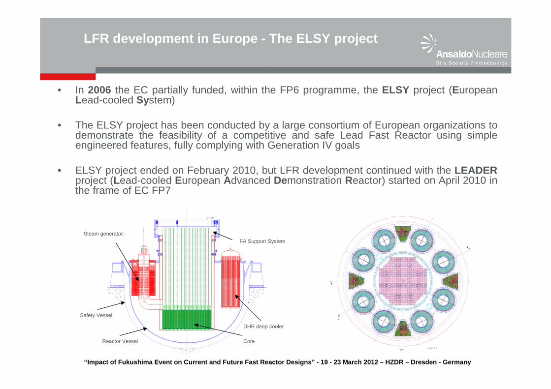
• In 2006 the EC partially funded, within the FP6 programme, the ELSY project (EuropeanLead-cooled System)
• The ELSY project has been conducted by a large consortium of European organizations todemonstrate the feasibility of a competitive and safe Lead Fast Reactor using simpleengineered features, fully complying with Generation IV goals
• ELSY project ended on February 2010, but LFR development continued with the LEADERproject (Lead-cooled European Advanced Demonstration Reactor) started on April 2010 inthe frame of EC FP7
B
B
C
C
Steam generator:FA Support System
DHR deep cooler
CoreReactor Vessel
Safety Vessel
“Impact of Fukushima Event on Current and Future Fa st Reactor Designs” - 19 - 23 March 2012 – HZDR – Dresd en - Germany
Advanced nuclear systems for increased sustainabili tyFP7-Fission 2009 2.2.1
Conceptual Design for Lead Cooled Fast Reactor Syst ems (LEADER)
� 16 European Organization are participating to the project� Ansaldo Nucleare is the Project Coordinator� 3 year Project (2010-2013), started April 1st 2010
LEADER Objectives� Deep analysis of the hard points of ELSY design to identify improvements with
the goal to reach an European Lead Fast Reactor (ELFR) configuration
� Definition of a new “frozen” ELFR configuration to be used as a reference plant
� Conceptual design of a scaled down facility respect to the reference plant theAdvanced Lead Fast Reactor European Demonstrator - ALFRED (300 MWth)
LFR development in Europe – The LEADER project
“Impact of Fukushima Event on Current and Future Fa st Reactor Designs” - 19 - 23 March 2012 – HZDR – Dresd en - Germany
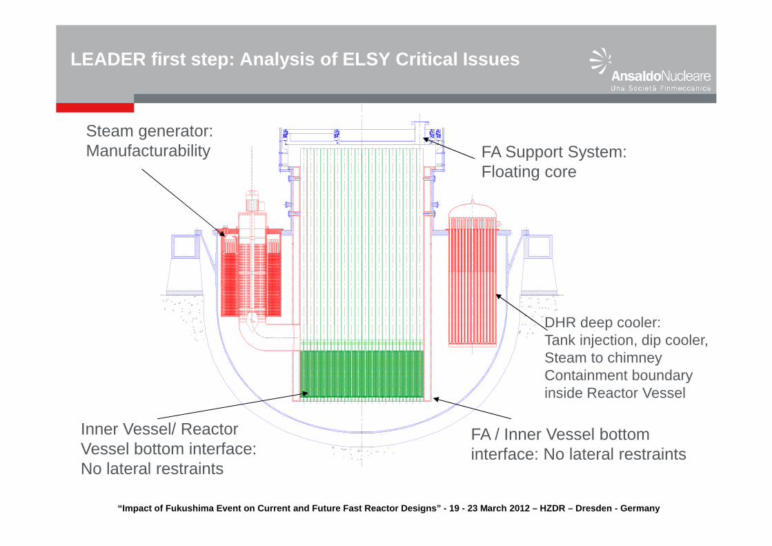
LEADER first step: Analysis of ELSY Critical Issues
Steam generator:Manufacturability FA Support System:
Floating core
DHR deep cooler:Tank injection, dip cooler,Steam to chimneyContainment boundary inside Reactor Vessel
FA / Inner Vessel bottom interface: No lateral restraints
Inner Vessel/ Reactor Vessel bottom interface:No lateral restraints
“Impact of Fukushima Event on Current and Future Fa st Reactor Designs” - 19 - 23 March 2012 – HZDR – Dresd en - Germany
LFR Design Evolution - from ELSY to ELFR
STRATEGY: Maintain the good solutions, change the rest
� SG manufacturability faced with a LEADER specific task
� Expected advantage of open square FA not verified, back to the wrapped option of ELSY, FA support provided, easy FA continuous monitoring for flow blockage
� Bottom grid introduced, lateral restraint for core and shroud, FAs weighted down by Tungsten ballast
� Need to develop alternative DHRs, ICS maintained.
“Impact of Fukushima Event on Current and Future Fa st Reactor Designs” - 19 - 23 March 2012 – HZDR – Dresd en - Germany
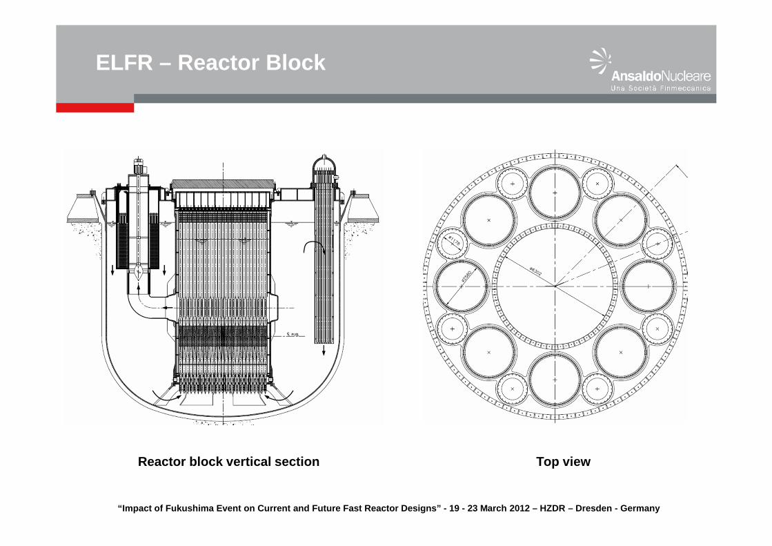
ELFR – Reactor Block
Reactor block vertical section Top view
“Impact of Fukushima Event on Current and Future Fa st Reactor Designs” - 19 - 23 March 2012 – HZDR – Dresd en - Germany
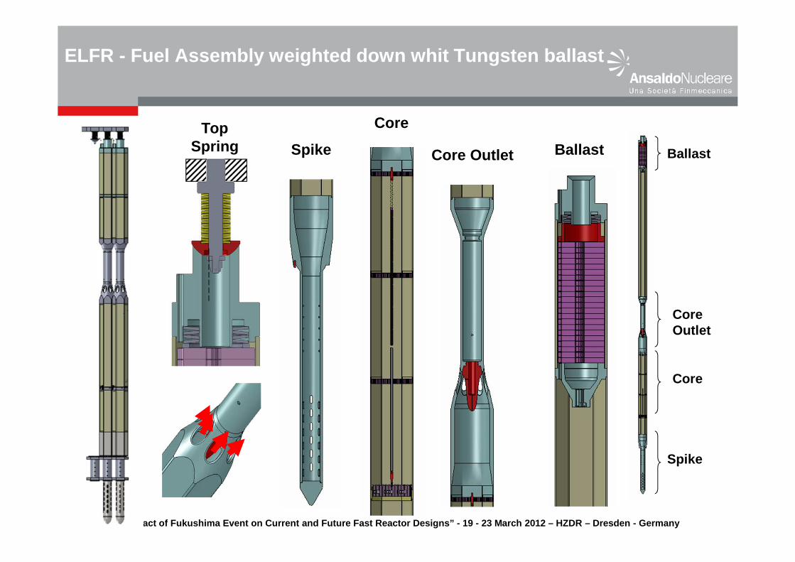
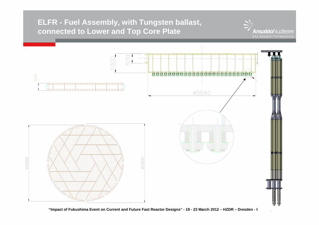
ELFR - Fuel Assembly weighted down whit Tungsten bal last
BallastCore Outlet
Core
Spike
Spike
Core
Core Outlet
Ballast
Top Spring
“Impact of Fukushima Event on Current and Future Fa st Reactor Designs” - 19 - 23 March 2012 – HZDR – Dresd en - Germany
ELFR - Fuel Assembly, with Tungsten ballast, connected to Lower and Top Core Plate
“Impact of Fukushima Event on Current and Future Fa st Reactor Designs” - 19 - 23 March 2012 – HZDR – Dresd en - Germany
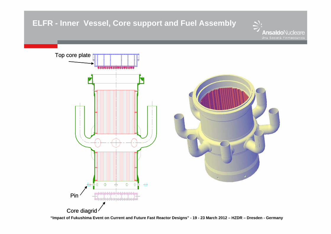
ELFR - Inner Vessel, Core support and Fuel Assembly
Top core plate
Core diagrid
Pin
Top core plate
Core diagrid
Pin
“Impact of Fukushima Event on Current and Future Fa st Reactor Designs” - 19 - 23 March 2012 – HZDR – Dresd en - Germany
ELFR – Control and Shutdown systems
2 independent passive shutdown systems
gravity driven system (only shutdown) passively inserted by a pneumatic system (by depressurization) from the top of the core. In case of failure of the pneumatic system, the safety rods are equipped with tungsten ballast that forces the absorber down by gravity with a lower velocity
control/shutdown system inserted from below the active core zone using the strong buoyancy available in lead. The inadvertent ejection from the core active part is avoided by means of a mechanical device in the core upper part to stop the control rod, once inserted, at the end of the active zone.
“Impact of Fukushima Event on Current and Future Fa st Reactor Designs” - 19 - 23 March 2012 – HZDR – Dresd en - Germany
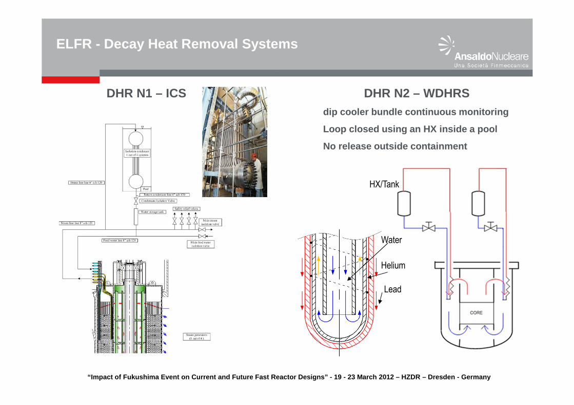
ELFR - Decay Heat Removal Systems strategy
One non safety-grade system, the secondary system, is used for the normal decay heat removal following the reactor shutdown
Two INDEPENDENT, DIVERSE , PASSIVE and REDUNDANTsafety-grade Decay Heat Removal systems (DHR N1 and DHR N2): in case of unavailability of the secondary system the DHR N1 system is called and in the unlike event of unavailability of DHR1 the DHR N2 is used to evacuate the decay heat
DHR N1: 4 Isolation Condenser Systems connected to 4 secondary systemsDHR N2: 4 Water Decay Heat Removal System in the cold pool (dip cooler)
DHR Systems features� Independence: two different systems with nothing in common� Diversity : two systems based on different physical principles � Redundancy: three loops sufficient to remove decay heat� Passive: Active actuation (but independent from grid), Passive operation
“Impact of Fukushima Event on Current and Future Fa st Reactor Designs” - 19 - 23 March 2012 – HZDR – Dresd en - Germany
ELFR - Decay Heat Removal Systems
Water
Helium
Lead
DHR N2 – WDHRSdip cooler bundle continuous monitoring
Loop closed using an HX inside a pool
No release outside containment
DHR N1 – ICS
HX/Tank
“Impact of Fukushima Event on Current and Future Fa st Reactor Designs” - 19 - 23 March 2012 – HZDR – Dresd en - Germany
Advantages of Lead and how they are used in the ELF R design
Lead does not react with water or airPossibility to eliminate the intermediate loop; SGU installed inside the Reactor VesselR&D needed on SGTR (no expected safety concern)No stringent requirements on reactor leak tightness
Lead has very high boiling point and very low Partial PressureReduced core voiding risk (Lead boiling point is 1745°C, Pressure at 400°C 3. 10-5 Pa)
Lead has a higher density than the oxide fuelNo need for core catcher to face core melt (molten clad and fuel dispersion)No risk of re-criticality in case of core melt
Lead is a low moderating medium and has low absorption cross-section.No compact Fuel Assembliesfuel rods p/d design not imposed by core designersCore pressure loss drastically reduced � high natural circulation capability
ELFR Advantages and Safety characteristics
“Impact of Fukushima Event on Current and Future Fa st Reactor Designs” - 19 - 23 March 2012 – HZDR – Dresd en - Germany
High Lead melting point (~ 327 °C) – assure Lead T above 340 °C
Overcooling transient (secondary side) may cause Lead freezing
Corrosion / erosion of structural materials due to lead environment.
Slugging of primary coolant loop (lead-oxide accumulation)
seismic risk due to large mass of lead
in-service inspection of core support structures
spent fuel management by remote handling
Steam Generator Tube rupture inside the primary system
Flow blockage and mitigation of core consequences
ELFR only Advantages? ���� Issues mainly operational
“Impact of Fukushima Event on Current and Future Fa st Reactor Designs” - 19 - 23 March 2012 – HZDR – Dresd en - Germany
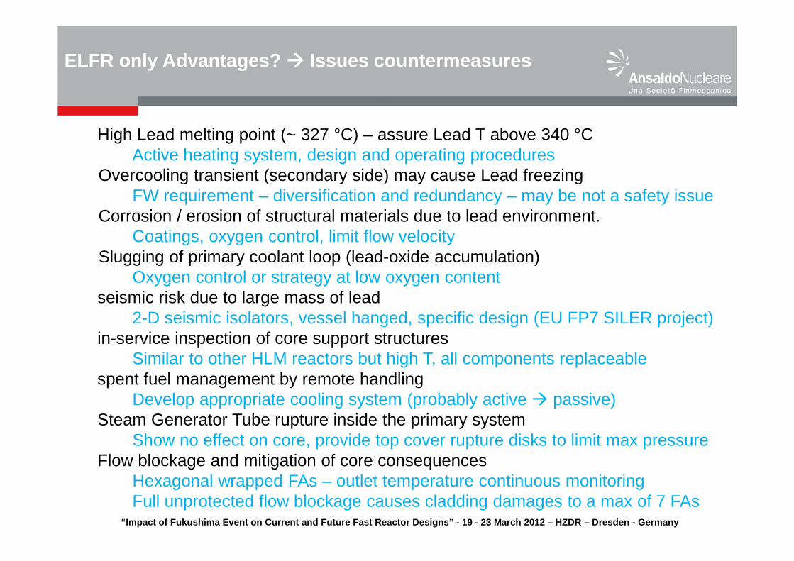
High Lead melting point (~ 327 °C) – assure Lead T above 340 °CActive heating system, design and operating procedures
Overcooling transient (secondary side) may cause Lead freezingFW requirement – diversification and redundancy – may be not a safety issue
Corrosion / erosion of structural materials due to lead environment.Coatings, oxygen control, limit flow velocity
Slugging of primary coolant loop (lead-oxide accumulation)Oxygen control or strategy at low oxygen content
seismic risk due to large mass of lead2-D seismic isolators, vessel hanged, specific design (EU FP7 SILER project)
in-service inspection of core support structuresSimilar to other HLM reactors but high T, all components replaceable
spent fuel management by remote handlingDevelop appropriate cooling system (probably active � passive)
Steam Generator Tube rupture inside the primary systemShow no effect on core, provide top cover rupture disks to limit max pressure
Flow blockage and mitigation of core consequencesHexagonal wrapped FAs – outlet temperature continuous monitoringFull unprotected flow blockage causes cladding damages to a max of 7 FAs
ELFR only Advantages? ���� Issues countermeasures
“Impact of Fukushima Event on Current and Future Fa st Reactor Designs” - 19 - 23 March 2012 – HZDR – Dresd en - Germany
ELFR SAFETY APPROACH
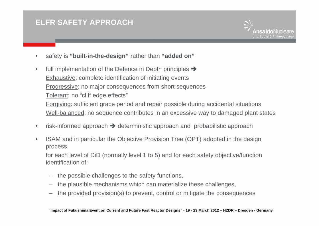
• safety is “ built-in-the-design ” rather than “ added on ”
• full implementation of the Defence in Depth principles �Exhaustive: complete identification of initiating eventsProgressive: no major consequences from short sequencesTolerant: no “cliff edge effects”Forgiving: sufficient grace period and repair possible during accidental situationsWell-balanced: no sequence contributes in an excessive way to damaged plant states
• risk-informed approach � deterministic approach and probabilistic approach
• ISAM and in particular the Objective Provision Tree (OPT) adopted in the design process.for each level of DiD (normally level 1 to 5) and for each safety objective/function identification of:
– the possible challenges to the safety functions,– the plausible mechanisms which can materialize these challenges,– the provided provision(s) to prevent, control or mitigate the consequences
“Impact of Fukushima Event on Current and Future Fa st Reactor Designs” - 19 - 23 March 2012 – HZDR – Dresd en - Germany
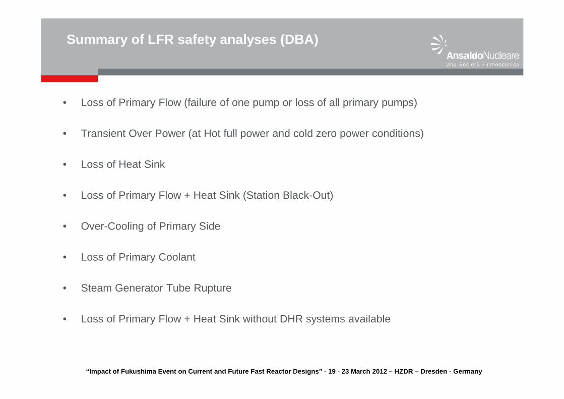
• Loss of Primary Flow (failure of one pump or loss of all primary pumps)
• Transient Over Power (at Hot full power and cold zero power conditions)
• Loss of Heat Sink
• Loss of Primary Flow + Heat Sink (Station Black-Out)
• Over-Cooling of Primary Side
• Loss of Primary Coolant
• Steam Generator Tube Rupture
• Loss of Primary Flow + Heat Sink without DHR systems available
Summary of LFR safety analyses (DBA)
“Impact of Fukushima Event on Current and Future Fa st Reactor Designs” - 19 - 23 March 2012 – HZDR – Dresd en - Germany
Summary of LFR safety analyses (DBA) ���� Results
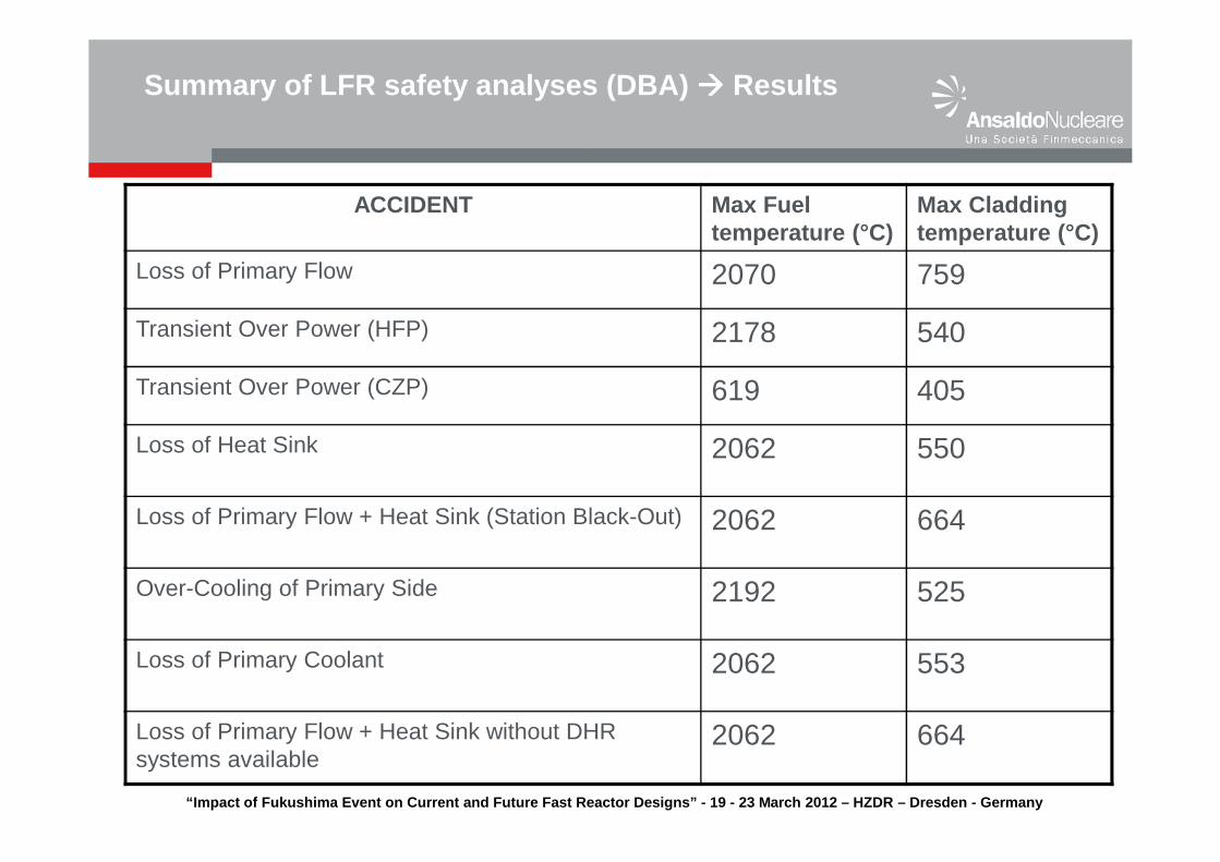
ACCIDENT Max Fuel temperature (°C)
Max Cladding temperature (°C)
Loss of Primary Flow 2070 759
Transient Over Power (HFP) 2178 540
Transient Over Power (CZP) 619 405
Loss of Heat Sink 2062 550
Loss of Primary Flow + Heat Sink (Station Black-Out) 2062 664
Over-Cooling of Primary Side 2192 525
Loss of Primary Coolant 2062 553
Loss of Primary Flow + Heat Sink without DHR systems available
2062 664
“Impact of Fukushima Event on Current and Future Fa st Reactor Designs” - 19 - 23 March 2012 – HZDR – Dresd en - Germany
Summary of LFR safety analyses (DBA) ���� Results
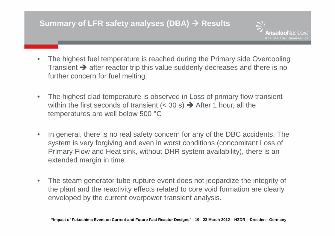
• The highest fuel temperature is reached during the Primary side Overcooling Transient � after reactor trip this value suddenly decreases and there is no further concern for fuel melting.
• The highest clad temperature is observed in Loss of primary flow transient within the first seconds of transient (< 30 s) � After 1 hour, all the temperatures are well below 500 °C
• In general, there is no real safety concern for any of the DBC accidents. The system is very forgiving and even in worst conditions (concomitant Loss of Primary Flow and Heat sink, without DHR system availability), there is an extended margin in time
• The steam generator tube rupture event does not jeopardize the integrity of the plant and the reactivity effects related to core void formation are clearly enveloped by the current overpower transient analysis.
“Impact of Fukushima Event on Current and Future Fa st Reactor Designs” - 19 - 23 March 2012 – HZDR – Dresd en - Germany
• There are only a few transients during which the core conditions could approach clad failure
• unprotected complete loss of all heat sinks with and/or without the operation of the primary pumps � clad temperature under EOC core conditions will most likely exceed limits, leading to possible local cladding failure (peak pins). No whole core clad failure is however to be expected.
• Potential positive reactivity insertions are judged to be enveloped by +200 pcminsertion in 10 sec case for HFP and by +350 pcm insertion in 10 sec case for CZP conditions. The results of the calculations have shown that power spikes exceeding a factor 1.6 nominal power are buffered as reactivity feedback effects decrease the power quickly towards nominal conditions.
• In order to prevent freezing of the lead coolant, a strict control of the secondary coolant conditions (feedwater inlet temperature, feedwater flow rate) is needed.
• In general, the safety analysis demonstrates the extremely forgiving nature of the ELFR design, ascribable to the intrinsic properties of the coolant taken and used from the beginning in the design of the core and primary system
Summary of LFR safety analyses (DEC)

“Impact of Fukushima Event on Current and Future Fa st Reactor Designs” - 19 - 23 March 2012 – HZDR – Dresd en - Germany
• Response to earthquakes enhanced �adoption of 2D seismic isolators (EU-FP7 SILER Project)
• Reactivity insertion due to core compaction anticipated �adoption of wrapped hexagonal FAs, with lateral restrains.
• Two Decay Heat Removal Systems independent, redundant and diverse
• DHR systems completely passive. Only actuation (through valves alignment) is active, using local stored energy �
the Station Blackout does not represent a concern any initiating event is managed without AC power
• Even in case of Station Blackout without DHR systems available, the safety analyses demonstrated that the fuel and cladding temperatures do not represent a concern
• Complete core melt is practically impossible due to favorable intrinsic lead characteristics: high thermal inertia, very high boiling point, higher density with respect to oxide fuel with enhancement of the fuel dispersion respect to fuel compaction.
• In the very unlikely event of an extreme Fukushima like scenario (or beyond) leading to the loss of all heat sinks (both DHR and secondary systems), the heat can still be extracted injecting water in the reactor cavity between the reactor and safety vessels, while in case of reactor vessel breach the decay heat can still be removed by the same system that cools the concrete of cavity walls.
LFR RESPONSE to extreme natural events
“Impact of Fukushima Event on Current and Future Fa st Reactor Designs” - 19 - 23 March 2012 – HZDR – Dresd en - Germany
• In the framework of the LEADER project, the safety approach for a Lead-cooled fast reactor has been defined and, in particular, all the possible challenges to the main safety functions and their mechanisms have been specified, in order to better define the needed provisions.
• On the basis of the above and taking into account the results of the safety analyses performed during previous project (ELSY), a reference configuration of the ELFR plant has been consolidated, by improving and updating the plant design features. In particular, the emerged safety concerns have been analyzed in the LEADER project and a new set of design options and safety provisions have been proposed.
• The combination of favourable Lead coolant inherent characteristics and plant design features, specifically developed to face identified challenges, resulted in a very robust and forgiving design, even in very extreme conditions, as a Fukushima-like scenario.
Conclusion
“Impact of Fukushima Event on Current and Future Fa st Reactor Designs” - 19 - 23 March 2012 – HZDR – Dresd en - Germany
Thank you for your attention