14 15 h1 forces students notes
TRANSCRIPT

JJ 2014 J1/ H1 Physics (8866) Forces
JJ Physics Department Page 1 of 21
Forces Content: 1. Types of forces
2. Equilibrium of forces
3. Centre of gravity
4. Turning effects of forces
(a) recall and apply Hooke’s law to new situations or to solve related problems
(b) deduce the elastic potential energy in a deformed material from the area under the force-extension graph
(c) describe the forces on mass, charge and current in gravitational, electric and magnetic fields, as appropriate.
(d) solve problems using the equation p = ρgh
(e) show a qualitative understanding of frictional forces and viscous forces including air resistance (No treatment of the coefficients of friction and viscosity is required)
(f) use a vector triangle to represent forces in equilibrium
(g) show an understanding that the weight of a body may be taken as acting at a single point known as its centre of gravity
(h) show an understanding that a couple is a pair of forces which tends to produce rotation only
(i) define and apply the moment of a force and the torque of a couple
(j) show an understanding that, when there is no resultant force and no resultant torque, a system is in equilibrium
(k) apply the principle of moments to new situations or to solve related problems

JJ 20
JJ Physics
Pre-Re DrawingFree-boacting uthe forcThe onlthat obforce. For eac 1) A
athfa
2) AoaaCN
3) A
D
14 J1/ H1 Phys
s Department
equisite S
g Free Bodyody diagramupon an objce is acting.ly rule for d
bject in the g
ch of the fol
An egg is frea tree. Neglehe forces aalling.
A hand is exon a book ina desk with accelerationConsider frNeglect air
A book is at Draw the FB
ics (8866)
kills
y Diagramsms (FBD) ar
ect in a give rawing freegiven situat
lowing case
ee-falling froect air resiscting on the
xerting a rign order to ma rightward
n. rictional forresistance
rest on a taBD of the bo
s (also knowre diagramsen situation
-body diagrtion. The re
es, draw the
om a nest instance. Drawe egg as it is
ghtward forcmove it acros
rces. e.
able-top. ook.
wn as Forces used to shn. The direc
rams is to dlative length
e forces act
n w s
ce ss
The noof actioenable
F on b(frictio
e Diagrams)how the magction of the
depict all thh of the forc
ting on the o
rmal contacton of weight,viewing.
F o
F on(norma
book by desk on)
(no
F
) gnitude andarrow revea
he forces wce indicates
object:
t force should but is shown
on book by Eart(weight)
Book
n book by desk al contact forc
F on book by (weight)
B
F on book by ormal contac
F on egg by Ea(weight)
d direction oals the direc
which act ONs the magni
ld be exactly n slightly sep
th
ce)
F on bo
Earth )
Book
desk ct force)
arth
Forces
Page 2 of 21
of all forces ction which
NLY ON tude of the
on the line parated to
ook by Hand

JJ 2014 J1/ H1 Physics (8866) Forces
JJ Physics Department Page 3 of 21
4) Ladder leaning against a rough vertical wall and a smooth horizontal surface.
Draw FBD for the identified objects. A
Traffic Light Point A
B
Car parked on a slope.
C
Ladder
A A
θ θ

JJ 2014 J1/ H1 Physics (8866) Forces
JJ Physics Department Page 4 of 21
D
E
(i) define and apply the moment of a force and the torque of a couple (h) show an understanding that a couple is a pair of forces which tends to produce
rotation only Moment of a Force
Consider a door as shown in Figure 1 (plan view), Taking moments about the hinge (pivot),
(Clockwise) Moment due to F, τ = F.d
• Units of F = N , • Units of d = m, • Units of τ = N m
Figure 1
Moment of a force on the body about any point is the product of that force and the perpendicular distance from that point to the line of action of the force.
m1 m2
m2
m1
Line of action of F
Hinge F
d
JJ 2014 J1/ H1 Physics (8866) Forces
JJ Physics Department Page 5 of 21
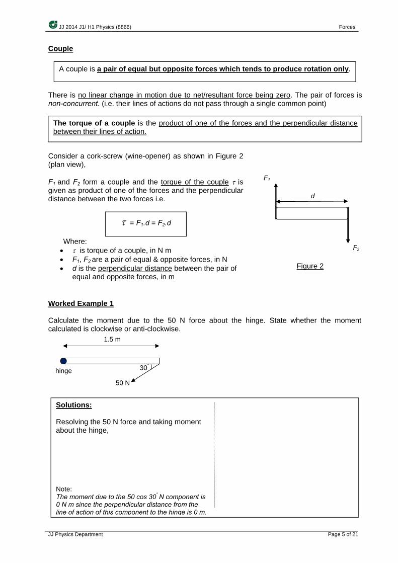
Couple
There is no linear change in motion due to net/resultant force being zero. The pair of forces is non-concurrent. (i.e. their lines of actions do not pass through a single common point)
Consider a cork-screw (wine-opener) as shown in Figure 2 (plan view), F1 and F2 form a couple and the torque of the couple τ is given as product of one of the forces and the perpendicular distance between the two forces i.e.
Where: • τ is torque of a couple, in N m • F1, F2 are a pair of equal & opposite forces, in N • d is the perpendicular distance between the pair of
equal and opposite forces, in m
Figure 2
Worked Example 1 Calculate the moment due to the 50 N force about the hinge. State whether the moment calculated is clockwise or anti-clockwise.
A couple is a pair of equal but opposite forces which tends to produce rotation only.
The torque of a couple is the product of one of the forces and the perpendicular distance between their lines of action.
τ = F1.d = F2.d
50 N
30° hinge
F2
F1
d
1.5 m
Solutions: Resolving the 50 N force and taking moment about the hinge, Note: The moment due to the 50 cos 30° N component is 0 N m since the perpendicular distance from the line of action of this component to the hinge is 0 m.

JJ 20
JJ Physics
WorkedA ruler are app
(j) sho
a (k) app
The terconstandescrib (Static) 1. Tr
Thfo In
Solut
14 J1/ H1 Phys
s Department
d Example of length 0
plied to the e
ow an undesystem is
ply the prin
rm “equilibrint velocity. ed as being
) Equilibriu
ranslation he vector s
orce
the directio
tions:
ics (8866)
2 0.30 m is piends of the
Wit
A
B
C
D
erstanding in equilibriciple of mo
ium” impliesFor this co
g in static e
um for poin
equilibriumum of all fo
on of the co
Σ
voted at itsruler, creat
What is the mis in the po
) 0.23 N m
) 0.39 N m
) 0.46 N m
) 0.60 N m
that, whenrium oments to n
s either theurse, we d
equilibrium.
nt masses
m orces acting
oordinate ax Fx = 0
s centre. Eqting a coupl
magnitude osition show
n there is n
new situati
e object is aeal mainly
g on any po
xes, mathem AND
Σ F =
qual and ople as shown
of the torquwn? [N99/
no resultan
ions or to s
at rest or thwith the fo
oint mass
matically,
D
= 0
pposite forcen.
e of the co/1/5]
t force and
solve relate
hat its centrrmer case,
must be ze
Σ Fy = 0
es of magn
uple on the
d no result
ed problem
re of mass in which th
ero i.e. no n
Forces
Page 6 of 21
nitude 2.0 N
e ruler when
ant torque,
ms
moves withhe object is
net/resultan
N
n
,
h s
t

JJ 2014 J1/ H1 Physics (8866) Forces
JJ Physics Department Page 7 of 21
(Static) Equilibrium for Rigid Bodies Two conditions must be satisfied for static equilibrium to take place for a rigid body.
1. Translation equilibrium
The resultant force acting on a rigid body must be zero In the direction of the coordinate axes, mathematically,
Σ Fx = 0 AND Σ Fy = 0
2. Rotational equilibrium The resultant torque acting on a rigid body must be zero
Mathematically, OR the total clockwise moments about a point is equal to the total anti-clockwise moments about the same point (i.e. Principle of Moments)
Principle of Moments Mathematically,
Note: All anti-clockwise moments can be taken to be positive and clockwise moments to be negative or vice versa.
To determine if point mass is in static equilibrium, 1) Draw free body diagram of point mass
2) Check for translational equilibrium i.e. Σ F = 0 To determine if a rigid body is in static equilibrium, 1) Draw free body diagram of rigid body 2) If external forces are concurrent (lines of action pass through a single common
point), then the body has rotational equilibrium (this means Σ τ = 0) - Only need to check for translational equilibrium i.e. Σ F = 0
3) If external forces are non-concurrent, - Check for translational equilibrium i.e. Σ F = 0 - Check for rotational equilibrium i.e. Σ τ = 0
FR = 0
For any body in rotational equilibrium, the total clockwise moments taken about any point is equal to the total anti-clockwise moments taken about the same point.
Σ τ = 0
Taking moments about any point (or axis), Σ clockwise moments = Σ anti-clockwise moments

JJ 2014 J1/ H1 Physics (8866) Forces
JJ Physics Department Page 8 of 21
(f) use a vector triangle to represent forces in equilibrium Two forces in equilibrium Consider two forces acting along the same line of action on a box which remains in equilibrium,
The 2 forces actually pass each other along the same line, but are drawn slightly separated for viewing purposes.
Analysis:
Since the 2 forces act along the same line of action (collinear), i.e. the forces pass through a common point Σ τ = 0
Since the box remains in equilibrium, the forces must be equal in magnitude and opposite in direction
Σ Fx = 0 ; F1 – F2 = 0 F1 = F2 (no resultant force)
Three forces in equilibrium Consider three forces acting on a box which remains in equilibrium,
Analysis:
Since the box remains in equilibrium: 1. There must be rotational equilibrium,
implying: • all forces must act on the same plane
(coplanar) • all forces must act through a common
point (concurrent forces). 2) There must be translational equilibrium,
implying: • the forces form a closed triangle (i.e.
FR = 0)
Four or more forces in equilibrium Consider four or more forces acting on a crate is in equilibrium,
Conclusion:
1) Forces must act on the same plane (coplanar)
2) Forces must all act through a common point. (concurrent forces)
3) Forces form a closed polygon. (FR = 0)
F1 F2 ··
F2
F1
F3
··
·
F1
F2 F3
F2
F1
F3
··
·F4 ·
F3
F1
F4
F2

JJ 20
JJ Physics
WorkedIn the dPQR.
WorkedThe diawire cothe tens
14 J1/ H1 Phys
s Department
d Example diagram bel
d Example agram belownnected besion in the w
ics (8866)
3 low, a body
4 w shows a hetween end wire is T.
y S of weigh
heavy flagpQ and a p
What isflagpoleA) PQB) PSC) PXD) QPE) SP
Solution
Solution
ht W hangs
If the systesection PQ
A) W cos 6B) W cos 6C) W tan 3D) W cos 3E) W tan 60
pole PQ hinoint R on th
s the directe?
:
:
s vertically b
m is in equQ?
60o cos 30o
60o 0o
30o 0o
ged at a vehe wall. The
tion of the
by a thread
ilibrium, wh
ertical wall ae weight of
force exert
d tied at Q t
hat is the ten
at end P anf the flagpo
ted by the [J8
Forces
Page 9 of 21
to the string
nsion in the[J85/1/2]
nd held by ale is W and
wall on the87/1/3]
g
e
a d
e

JJ 2014 J1/ H1 Physics (8866) Forces
JJ Physics Department Page 10 of 21
Worked Example 5 A uniform rod of length 7.00 m and mass 5.0 kg is pivoted as shown.
Draw a free-body diagram for the rod and determine
(a) the mass m which must be attached to maintain static equilibrium with the rod horizontal;
(b) the reaction force, R, experienced at the pivot. (Take g = 9.81 m s-2)
Solution:
(a) Taking moments about pivot (so that R need not be considered in our analysis), and
applying Principle of Moments, Σ clockwise moments = Σ anti-clockwise moments
(5g)(3.5 - 2 ) = (mg)(2 ) (b) For static equilibrium to occur, Σ Fy = 0 R – 3.75g – 5g = 0 (Taking upwards as positive) R = 8.75g =
Summary of Equilibrium of Forces
2 m 5 m
m

JJ 20
JJ Physics
14 J1/ H1 Phys
s Department
Gra
~
E
~a
M
~affm
Wea~ ra
Stron~fonu
ics (8866)
Non-Co~influ
di
avitationa[Topic 7
~affects m
Electric F[Topic 1
affects ch
Magnetic F[Topic 1
fects magoving ch
ak Nuclearesponsibdioactive
ng Nucleorce holdiucleus tog
ontact Fouence ovestances
al Force 7]
mass
orce2]arges
Force5]
gnets & arges
ar Forceble for decay
ar Forceng the
gether
Force
rceser
es
Cont~requir
exe
~ AUp
~
Ot
tact Forceres contacert a force
Spring ~ Hooke
F = kx , E
UpthArchimedepthrust = w
displa
FrictionaViscous e.g. air re
TensCompre
~ropes ontens
ther Conte.g. friction
contact
esct to
e
Forcee’s law
EP = ½kx2
hrustes’ Principl
weight of fluiaced
al Force / Forces
esistance
ion / essionly provide
sion
tact Forcn, normal t force
Forces
Page 11 of 21
ed
e
ce

JJ 2014 J1/ H1 Physics (8866) Forces
JJ Physics Department Page 12 of 21
(a) recall and apply Hooke’s law to new situations or to solve related problems Hooke’s Law Mathematically,
xF ∝
Therefore,
kxF =
where:
• F is the external force required to extend (or compress) the wire or spring, (unit: N) • k is a positive constant known as the force constant or spring constant, (unit: N m-1) • x is extension (or compression) of the wire or spring , (unit: m)
Note: Extension refers to an increase in length and compression refers to a decrease in length. (These do not include the original length)
Sketch the graph of F – x.
(b) deduce the elastic potential energy in a deformed material from the area under the force-extension graph
Elastic potential energy, also known as the strain energy, is the energy stored in a body due to its elastic deformation. (i.e. extension or compression) It can be deduced from the area under the F - x graph as seen in the following page:
Hooke’s Law states that the force F required to stretch (or compress) an object (e.g. spring, wire) is directly proportional to the amount of extension (or compression) x, if the limit of proportionality is not exceeded.
F = kx F / N
x / m

JJ 2014 J1/ H1 Physics (8866) Forces
JJ Physics Department Page 13 of 21
E.g. Consider a spring which can be stretched horizontally by a force F as shown in Figure 1(b) from its equilibrium position as seen in Figure 1(a).
Figure 1(a): Unstretched spring
Figure 1(b)
The work done by F, ∆W, in stretching the spring by xΔ is
∆xkx)∆xFW (==Δ
In general, the work done by F, W, in stretching the spring from extension x = 0 to x = x is
∫∫ ==x
o
x
odx(kx)dxFW
Hence,
The work done in stretching the spring is stored as elastic potential energy or strain energy in the spring.
Area under the F – x graph
))((21 baseheight=
))((21 xF= ))((
21 xkx=
2
21 kx=
Note: This formula is ONLY true for systems that obey Hooke’s law. For systems that do not obey Hooke’s law, work done = area under F-x graph.
Work done in stretching a spring, W = 212
kx , unit of W is joule, J
= area under the F - x graph
F/N
x/m
F = kx
x
F
x = 0 x = 0
∆x
x = x

JJ 2014 J1/ H1 Physics (8866) Forces
JJ Physics Department Page 14 of 21
Worked Example 6 A sample is placed in a tensile testing machine. It is extended by known amounts and the tension is measured.
What is the work done on the sample when it is given a total extension of 9 mm? [J99/I/23]
A) 0.31 J
B) 0.36 J
C) 0.43 J
D) 0.72 J
Worked Example 7 The graph shows the relationship between load F and extension x for a certain spring.
A load of 6.0 N is placed on the spring. What additional strain energy will be stored in the spring if it is then extended a further 0.01 m? [J94/I/22]
A) 0.010 J
B) 0.060 J
C) 0.070 J
D) 0.160 J
Solution:
Solution:

JJ 2014 J1/ H1 Physics (8866) Forces
JJ Physics Department Page 15 of 21
(c) describe the forces on mass, charge and current in gravitational, electric and magnetic fields, as appropriate.
In Physics, a field refers to a region of space within which a force is experienced. A gravitational field due to a mass is a region of space within which a gravitational force is experienced by another mass. An electric field due a charge is a region of space within which an electric force is experienced by another charge. A magnetic field is a region of space within which a magnetic force is experienced by a moving charge.
Type of forces Nature of forces Description
Gravitational Force, Fg
Acts on masses
- Attractive force that acts between any two masses. - Direction of force always in the direction of the external gravitation field strength
Electric Force, FE
Acts on electric charges
- Attractive or repulsive force that acts between any two electric charges. - For positive charges, direction of force is always in the direction of an external electric field - For negative charges, direction of force is always opposite to the direction of an external electric field
Magnetic Force, FM
Acts on magnets, moving charges or
current carrying conductors
- Attractive or repulsive force experienced by current carrying conductor in an external magnetic field. - If the conductor is placed parallel to the magnetic field, no force is experienced. Otherwise, it will experience a force given by Fleming’s Left Hand Rule.
• Electric and magnetic forces will be discussed in greater details in the topics “Electric Fields” and “Electromagnetism” respectively.
m1 m2 Fg -Fg
-FE FE
FE -FE
FE -FE

JJ 2014 J1/ H1 Physics (8866) Forces
JJ Physics Department Page 16 of 21
(d) solve problems using the equation p = ρgh A fluid is a collection of molecules that are randomly arranged and held together by weak cohesive forces and by forces exerted by the walls of a container i.e. it is a substance which can flow. Both liquids and gases are fluids.
Fluid pressure increases with depth. Water pressure increases with depth. Likewise, atmospheric pressure decreases with increasing altitude (height).
Consider a cylinder of fluid with height h as shown in Figure 2, The fluid pressure p (at the base of container) is given by
ghp ρ= where:
• p is the pressure due to the fluid (liquid or gas) at depth h, (unit: Pa)
• ρ is the density of the fluid, (unit: kg m-3) • g is the acceleration of free fall, (unit: m s-2) • h is the depth of the fluid, (unit: m)
Figure 2
Note:
1. Pressure is a scalar quantity.
2. The fluid density ρ is assumed to be constant (i.e. the fluid is incompressible)
3. The fluid pressure p is equal (in all directions) at all points having the same depth, independent of the shape of the container.
4. The equation p = ρgh allows the pressure due to the fluid to be calculated. It should be remembered that the actual pressure at depth h in a liquid would be given by
pressure at depth h = ρgh + atmospheric pressure at liquid surface
(pressure due to fluid only)
h Liquid of density
pressure p at base of container
·

JJ 20
JJ Physics
WorkedA long then inc
WorkedA tall coLiquid M
SolutioVertic Press
Solut
14 J1/ H1 Phys
s Department
d Example narrow tubeclined at 30
d Example ontainer whM has a den
on: cal height of
ure at X =
ion:
ics (8866)
8 e is filled wo to the hor
9 hich is opennsity which
Wh
f water abov
with water ofizontal as s
If tpresA) 5B) 1C) 9D) 1E) 1
to the atmois twice as
Which graphheight, x, ab
ve X =
f density 10shown. (Tak
he atmospssure at po5.00 kPa 10.0 kPa 95.0 kPa 105 kPa 110 kPa
osphere cogreat as tha
h shows hobove the ba
020 kg m-3 ke g = 9.81
pheric presint X, inside
ntains a layat of liquid L
ow the presse of the co
to a depth m s-2)
ssure is 10e the tube?
yer of liquid L.
ssure, p, at ontainer?
of 1.00 m.
00 kPa, w [N
L, floating
a point va
Forces
Page 17 of 21
The tube is
what is theN91/1/21]
on liquid M
ries with its[J93/1/23]
s
e
.
s
JJ 2014 J1/ H1 Physics (8866) Forces
JJ Physics Department Page 18 of 21
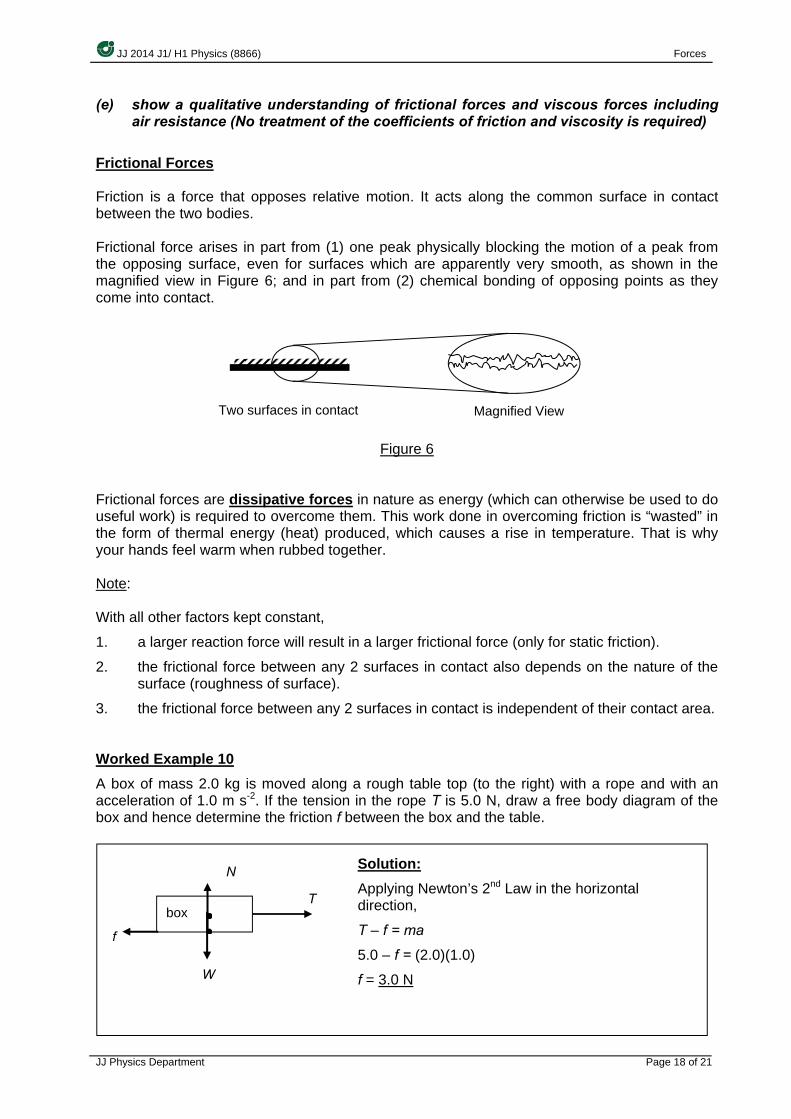
(e) show a qualitative understanding of frictional forces and viscous forces including air resistance (No treatment of the coefficients of friction and viscosity is required)
Frictional Forces Friction is a force that opposes relative motion. It acts along the common surface in contact between the two bodies. Frictional force arises in part from (1) one peak physically blocking the motion of a peak from the opposing surface, even for surfaces which are apparently very smooth, as shown in the magnified view in Figure 6; and in part from (2) chemical bonding of opposing points as they come into contact.
Figure 6 Frictional forces are dissipative forces in nature as energy (which can otherwise be used to do useful work) is required to overcome them. This work done in overcoming friction is “wasted” in the form of thermal energy (heat) produced, which causes a rise in temperature. That is why your hands feel warm when rubbed together. Note: With all other factors kept constant,
1. a larger reaction force will result in a larger frictional force (only for static friction).
2. the frictional force between any 2 surfaces in contact also depends on the nature of the surface (roughness of surface).
3. the frictional force between any 2 surfaces in contact is independent of their contact area. Worked Example 10 A box of mass 2.0 kg is moved along a rough table top (to the right) with a rope and with an acceleration of 1.0 m s-2. If the tension in the rope T is 5.0 N, draw a free body diagram of the box and hence determine the friction f between the box and the table.
box
f
T
W
N Solution: Applying Newton’s 2nd Law in the horizontal direction,
T – f = ma
5.0 – f = (2.0)(1.0)
f = 3.0 N
··
Two surfaces in contact Magnified View

JJ 2014 J1/ H1 Physics (8866) Forces
JJ Physics Department Page 19 of 21
Viscous force (Friction in fluids) It is the frictional force acting on a body when the body moves through a fluid i.e. a liquid or gas and dissipative in nature. Examples of viscous force are air resistance acting on a moving car and object falling in air. Viscous force arises in fluids because there are attractive forces between fluid molecules. Viscous force increases proportionally with speed in laminar flow conditions (when each particle of the fluid follows a smooth path and the paths of each particle do not cross each other). Above a critical speed, the fluid flow becomes irregular and turbulent and viscous force increases proportionally with the square of speed.
Comparison between Frictional Forces and Viscous Forces
Similarities Differences
Both are dissipative forces in nature i.e. work is done in overcoming these forces.
Frictional forces exist even when solids are at rest, whereas
viscous forces exist only when there is relative motion between solid and fluid i.e. the solid is moving in the fluid. Both are contact forces.
Both occur due to the electrostatic forces between molecules.
Frictional forces between solids are independent of velocity, whereas viscous forces depends on velocity.
(f) show an understanding that the weight of a body may be taken as acting at a single point known as its centre of gravity
Centre of Gravity
The weights w of n individual particles of an object are effectively parallel to each other as seen in Figure in 7(a).
Figure 7(a) The weight W of an object is the resultant force of all the individual weights w of its particles in the object and is directed towards the centre of the Earth.
The centre of gravity, G of a rigid body is the single point through which the weight of the object appears to act.
· · · · · · · · · · · · · ·w1 w2 w3 w4 wn wn-1 … …
JJ 2014 J1/ H1 Physics (8866) Forces
JJ Physics Department Page 20 of 21
Figure 7(b)
The factors affecting position of centre of gravity are (1) distribution of the masses; and (2) the acceleration of free fall g.
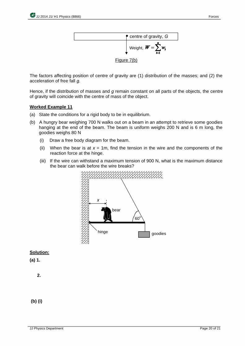
Hence, if the distribution of masses and g remain constant on all parts of the objects, the centre of gravity will coincide with the centre of mass of the object. Worked Example 11 (a) State the conditions for a rigid body to be in equilibrium.
(b) A hungry bear weighing 700 N walks out on a beam in an attempt to retrieve some goodies hanging at the end of the beam. The beam is uniform weighs 200 N and is 6 m long, the goodies weighs 80 N
(i) Draw a free body diagram for the beam.
(ii) When the bear is at x = 1m, find the tension in the wire and the components of the reaction force at the hinge.
(iii) If the wire can withstand a maximum tension of 900 N, what is the maximum distance the bear can walk before the wire breaks?
Solution: (a) 1.
2.
(b) (i)
centre of gravity, G
Weight,
·
hinge
600
goodies
bear
x

JJ 2014 J1/ H1 Physics (8866) Forces
JJ Physics Department Page 21 of 21
(ii)
(iii) Taking moment about hinge,
Total anticlockwise moment = total clockwise moment
900 sin 600 x 6 = (700)(x) + 200 x 3 + 80 x 6
x = 5.14 m
---The End---
Reference Textbooks:
1) Serway/Faughn, College Physics 6th Ed.(Int. Student Ed), Thomson Learning 2003 2) Loo Kwok Wai, Longman Advanced Level Physics, Pearson Ed. 2006 3) Robert Hutchings, Physics 2nd Ed., Nelson 2000 4) Paul G. Hewitt, Conceptual Physics 9th Ed., Addison Wesley 2002
Video:
1) The Science of NFL Football : Torque and Center of Mass 2) Visualization of Torques (Moments) 3) Torque and Centre of Mass (khanacademy.org) http://www.youtube.com
80 N
700 N 200 N