13.56mhz contactless smart card reader 13.56mhz ... - ip … · 10-3-1. basic operations 1. after...
TRANSCRIPT
User’s Manual
13.56MHz Contactless Smart Card Reader
13.56MHz Contactless Universal Smart Card Reader Fingerprint-Stored Smart Card ID-Only Reader

2
Table of Contents
1. Important Safety Instructions ................................................................ 3 2. General................................................................................................. 4 3. Features ............................................................................................... 4 4. Identifying Supplied Parts ..................................................................... 5 5. Specification ......................................................................................... 6 6. Installation ............................................................................................ 8 7. Wire Color Table ................................................................................. 10 8. Output Format .................................................................................... 10 9. Wire Connection to Access Controller ................................................ 13 10. Operations ........................................................................................ 14 11. Applendix .......................................................................................... 16 12. FCC Registration Information ........................................................... 17 13. Warranty Policy and Limitation of Liability ........................................ 18 14. Template ........................................................................................... 19

3
1. Important Safety Instructions When using the 13.56MHz [MIFARE] Contactless Smart Card Reader (SRK101) / 13.56MHz Contactless Universal Smart Card Reader (SRK101U) / Fingerprint Stored Smart Card ID Only Reader (SRK101B), basic safety precautions should always be followed to reduce the risk of fire, electrical shock, and injury to persons. In addition, the following should also be followed: 1. Fully read and understand all instructions and follow them completely. 2. Follow all warnings and instructions marked on the product.
3. Do not use liquid or aerosol cleaners. Use a damp cloth for cleaning. If necessary, use mild soap.
4. Do not use this product near water.
5. Only operate this product using the type of power source indicated. If you are not sure of the type of power supplied to your installation site, consult your dealer of local power company.
6. Never insert objects of any kind into the product or through the cabinet slots as they may touch
voltage points and/or short circuit parts possibly resulting in fire or electric shock. Never spill liquid of any kind on the product.
7. Never disassemble this product by yourself; take the unit to a qualified service center whenever service or repair is required. Opening or removing the covers may expose you to dangerous voltages or other risks. Also, incorrect reassembly can cause electric shock when the unit is subsequently used.
8. Unplug this product from the Direct Current (DC) power source and refer to qualified service
personnel under these conditions: When the power supply cord or plug is damaged or frayed. If liquid has been spilled on the product. If the product does not operate normally after following the operating instructions in this
manual. Adjust only those controls that are covered by the operating instructions in this manual. Improper adjustment of other controls that are not covered by this manual may damage the unit and will often require extensive work by a qualified technician to restore normal operation.
If the product exhibits a distinct change in performance.

4
2. General
The IDTECK SR101/SR101U/SR101B Smart Card Reader is a proximity reader with the read range of up to 4 inches (10cm). The IDTECK SR101/SR101U/SR101B Smart Card Reader has a built-in keypad with night-vision backlighting which makes operation at night convenient. IDTECK SR101 reads the serial number stored on the Philips Mifare™ card (ISO14443 Type A) and transmits the data to the controller in various formats. IDTECK SR101U reads the serial number stored on the ISO14443 Type A/B card and transmits the data to the controller in various formats. IDTECK SR101B reads the IDs stored on the user cards that have been issued using the PRG2000B and transmits the data to the controller in various formats. 3 LED indicators (red, green, and yellow) and a built-in Piezo buzzer will guarantee you accurate and reliable system operations.
3. Features
Common - 13.56MHz [MIFARE] Contactless Smart Card & PIN Reader - Read Range: Up to 4 inches (10cm) - User-Defined Formats Available - 4 / 8bit Burst Output Format Available - 12-Button Keypad - External LED Control - External Buzzer Control - Tamper Switch - Wall Mount (US, EU, Asian Gang Box Size) - Reverse Polarity Protection - Options: 3ea of External LED Control Supervisory Signal
SRK101 - ISO 14443 type A compatible - Serial Number Read only - 34bit Wiegand (default) / RS232, ABA Track II (optional) Output Format - Compatible Controller: iCON100SR, iTDC-SR, Third Party Controller
FINGER007SR, FACE007SR, SR505

5
SRK101U - ISO 14443 type A/B compatible - Serial Number Read only - 34bit Wiegand (default) / RS232, ABA Track II (optional) Output Format - Compatible Controller: iCON100SR, iTDC-SR, Third Party Controller
FINGER007SR, FACE007SR, SR505
SRK101B - Read Encrypted ID of Smart Card that is written by PRG2000B - 26bit Wiegand (default) / RS232, ABA Track II (optional) Output Format - Compatible Controller: iCON100, iTDC, FINGER007SRB, Third Party Controller. - Compatible Reader: SR10B, SR30B, FGR006SRB, FINGER006SRB
4. Identifying Supplied Parts Please unpack and check the contents of the box:
SRK101/SRK101U/SRK101B Wall Mount O-Ring User’s Manual
(1ea) (1ea) (5ea) (1 Copy)
3.5*40 Screws 3.5*12 Screws Anchor Bolts (4ea) (4ea) (4ea)

6
5. Specification
Model SRK101 SRK101U SRK101B
Read Range Type A ISK50 / IMC135: up to 2 inches (5cm)
ISC80: up to 4 inches (10cm)
Type B N/A ISC80B: up to 4 inches (10cm) N/A
Card Reading Time 30ms
Power / Current DC12V / Max. 180mA
Input Port Default 1ea of External LED Control,
1ea of External Buzzer Control
Optional 3ea of External LED Control, 1ea of External Buzzer Control
Output Port 34bit Wiegand(Default)
RS232(Default) 26bit
Wiegand(Default) RS232(Default)
4/8bit Burst for PIN (Selectable) / ABA Track II (Optional)
Keypad 12-button Keypad
LED Indicator 3 Array LED Indicators (Red, Green, Yellow)
Buzzer Piezo Buzzer
Operating Temperature -35° ~ +65°C ( -31°F ~ +149°F )
Operating Humidity 10% ~ 90% Relative Humidity (Non-condensing)
Color Dark Pearl Gray
Material Polycarbonate
Dimensions (W x H x T) 87mm x 100mm x 31mm (3.4” x 3.94” x 1.22”)
Weight 190g (0.42lbs)
Certifications FCC, CE, MIC
7
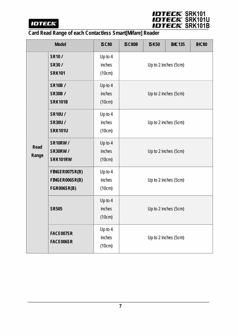
Card Read Range of each Contactless Smart[Mifare] Reader
Model ISC80 ISC80B ISK50 IMC135 IHC80
Read Range
SR10 / SR30 / SRK101
Up to 4 inches (10cm)
Up to 2 inches (5cm)
SR10B / SR30B / SRK101B
Up to 4 inches (10cm)
Up to 2 inches (5cm)
SR10U / SR30U / SRK101U
Up to 4 inches (10cm)
Up to 2 inches (5cm)
SR10RW / SR30RW / SRK101RW
Up to 4 inches (10cm)
Up to 2 inches (5cm)
FINGER007SR(B) FINGER006SR(B) FGR006SR(B)
Up to 4 inches (10cm)
Up to 2 inches (5cm)
SR505 Up to 4 inches (10cm)
Up to 2 inches (5cm)
FACE007SR FACE006SR
Up to 4 inches (10cm)
Up to 2 inches (5cm)
8
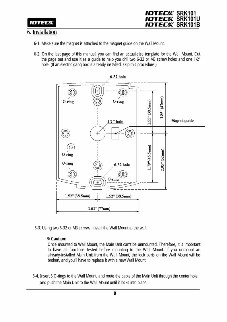
6. Installation
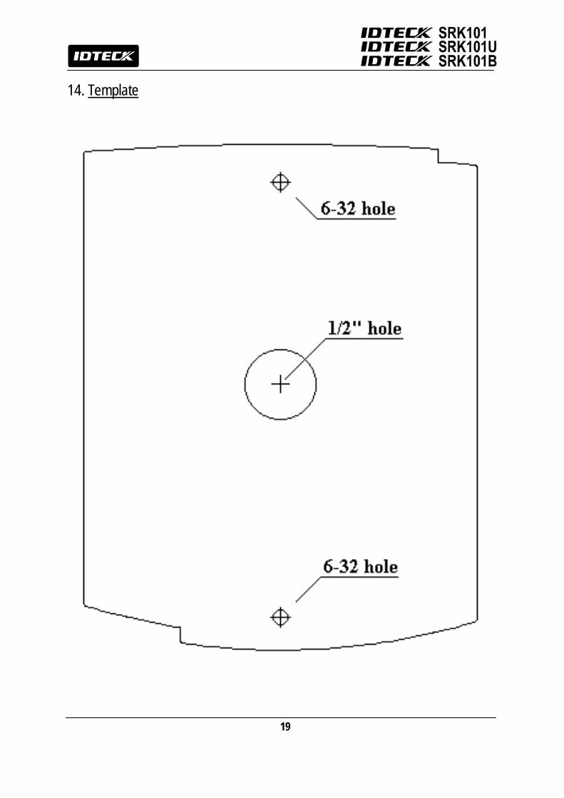
6-1. Make sure the magnet is attached to the magnet guide on the Wall Mount. 6-2. On the last page of this manual, you can find an actual-size template for the Wall Mount. Cut
the page out and use it as a guide to help you drill two 6-32 or M3 screw holes and one 1/2" hole. (If an electric gang box is already installed, skip this procedure.)
6-3. Using two 6-32 or M3 screws, install the Wall Mount to the wall.
※Caution: Once mounted to Wall Mount, the Main Unit can’t be unmounted. Therefore, it is important to have all functions tested before mounting to the Wall Mount. If you unmount an already-installed Main Unit from the Wall Mount, the lock parts on the Wall Mount will be broken, and you’ll have to replace it with a new Wall Mount.
6-4. Insert 5 O-rings to the Wall Mount, and route the cable of the Main Unit through the center hole and push the Main Unit to the Wall Mount until it locks into place.
Magnet guide
9
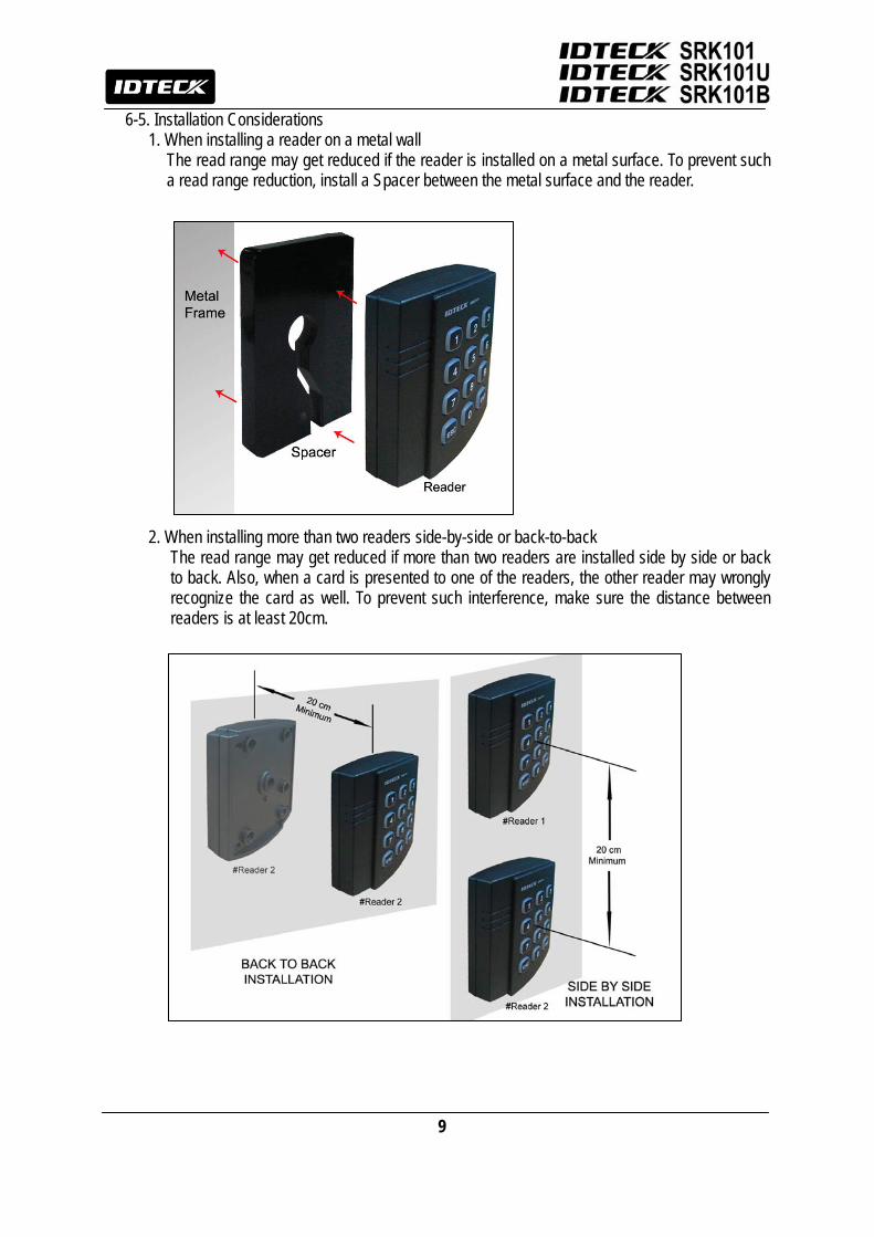
6-5. Installation Considerations 1. When installing a reader on a metal wall
The read range may get reduced if the reader is installed on a metal surface. To prevent such a read range reduction, install a Spacer between the metal surface and the reader.
2. When installing more than two readers side-by-side or back-to-back The read range may get reduced if more than two readers are installed side by side or back to back. Also, when a card is presented to one of the readers, the other reader may wrongly recognize the card as well. To prevent such interference, make sure the distance between readers is at least 20cm.
10
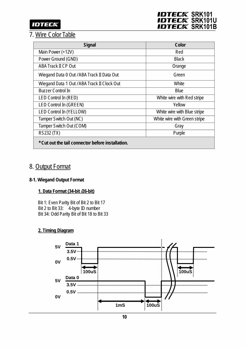
7. Wire Color Table
8. Output Format
8-1. Wiegand Output Format
1. Data Format (34-bit /26-bit)
Bit 1: Even Parity Bit of Bit 2 to Bit 17 Bit 2 to Bit 33: 4-byte ID number Bit 34: Odd Parity Bit of Bit 18 to Bit 33
2. Timing Diagram
3.5V0.5V
100uS
1mS
Data 0 100uS
100uS
Data 1
3.5V0.5V
5V
5V
0V
0V
Signal Color Main Power (+12V) Red Power Ground (GND) Black ABA Track II CP Out Orange
Wiegand Data 0 Out / ABA Track II Data Out Green
Wiegand Data 1 Out / ABA Track II Clock Out White Buzzer Control In Blue LED Control In (RED) White wire with Red stripe LED Control In (GREEN) Yellow LED Control In (YELLOW) White wire with Blue stripe Tamper Switch Out (NC) White wire with Green stripe Tamper Switch Out (COM) Gray RS232 (TX) Purple
* Cut out the tail connector before installation.

11
8-2 4bit and 8bit Burst Output Format (Keypad)
1. Data Format
(4bit Burst output format)
Keypads Binary Hexa Keypads Binary Hexa 0 0000 0 6 0110 6 1 0001 1 7 0111 7 2 0010 2 8 1000 8 3 0011 3 9 1001 9 4 0100 4 ESC 1010 A 5 0101 5 ENT 1011 B
(8bit Burst output format)
Keypads Binary Hexa Keypads Binary Hexa 0 11110000 F0 6 10010110 96 1 11100001 E1 7 10000111 87 2 11010010 D2 8 01111000 78 3 11000011 C3 9 01101001 69 4 10110100 B4 ESC 01011010 5A 5 10100101 A5 ENT 01001011 4B
2. Timing Diagram
3.5V0.5V
100uS
1mS
Data 0 100uS
100uS
Data 1
3.5V0.5V
5V
5V
0V
0V

12
8-3 RS-232 (Option) Output Format
1. Data Format (Baud Rate : 9600bps)
2. Data Structure
START(0X02H) DATA(8 Char) END (0x03H) LRC (Card Output)
START(0X02H) DATA(1~8 Char) END (0x03H) LRC (Keypad Output)
+15V
-15V
+3V
-3V
Space (=0)
Mark (=1)
8 Data Bits2 Stop Bits
IndeterminateRegion
Data packet corresponding to ASCII character 'A'Start Bit
0 1 0 0 0 0 0 1 0LSB MSB
0V
13
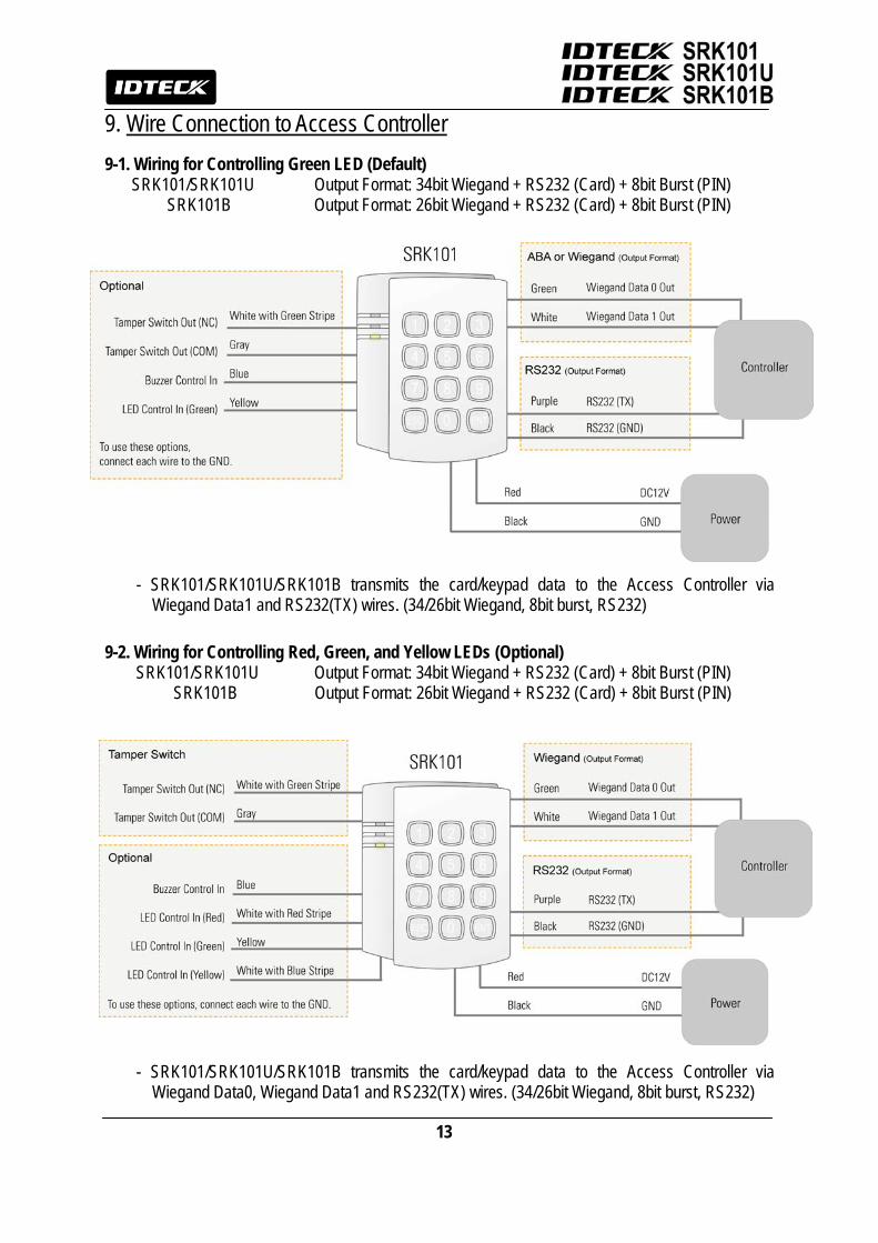
9. Wire Connection to Access Controller 9-1. Wiring for Controlling Green LED (Default)
SRK101/SRK101U Output Format: 34bit Wiegand + RS232 (Card) + 8bit Burst (PIN) SRK101B Output Format: 26bit Wiegand + RS232 (Card) + 8bit Burst (PIN)
- SRK101/SRK101U/SRK101B transmits the card/keypad data to the Access Controller via Wiegand Data1 and RS232(TX) wires. (34/26bit Wiegand, 8bit burst, RS232)
9-2. Wiring for Controlling Red, Green, and Yellow LEDs (Optional)
SRK101/SRK101U Output Format: 34bit Wiegand + RS232 (Card) + 8bit Burst (PIN) SRK101B Output Format: 26bit Wiegand + RS232 (Card) + 8bit Burst (PIN)
- SRK101/SRK101U/SRK101B transmits the card/keypad data to the Access Controller via Wiegand Data0, Wiegand Data1 and RS232(TX) wires. (34/26bit Wiegand, 8bit burst, RS232)
14
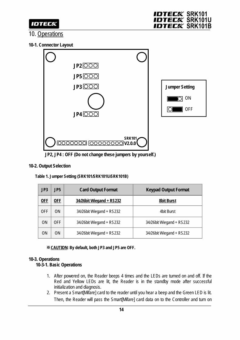
10. Operations 10-1. Connector Layout
JP2, JP4 : OFF (Do not change these jumpers by yourself.)
10-2. Output Selection
Table 1. Jumper Setting (SRK101/SRK101U/SRK101B)
JP3 JP5 Card Output Format Keypad Output Format
OFF OFF 34/26bit Wiegand + RS232 8bit Burst
OFF ON 34/26bit Wiegand + RS232 4bit Burst
ON OFF 34/26bit Wiegand + RS232 34/26bit Wiegand + RS232
ON ON 34/26bit Wiegand + RS232 34/26bit Wiegand + RS232
※CAUTION: By default, both JP3 and JP5 are OFF.
10-3. Operations 10-3-1. Basic Operations
1. After powered on, the Reader beeps 4 times and the LEDs are turned on and off. If the Red and Yellow LEDs are lit, the Reader is in the standby mode after successful initialization and diagnosis.
2. Present a Smart[Mifare] card to the reader until you hear a beep and the Green LED is lit. Then, the Reader will pass the Smart[Mifare] card data on to the Controller and turn on
SRK101 V2.0.0
JP4
JP3
JP5
JP2
Jumper Setting ON OFF

15
the Yellow LED, indicating that it’s waiting for another card to be read. 3. Press the keypad and you’ll hear a beep. Then, the reader will pass the keypad input
data on to the controller. 4. In the 34bit Wiegand + RS232 output format (SRK101 or SRK101U), an ID (PIN) is in the
range of 0 to 4294967295, without a facility code. In the 26bit Wiegand + RS232 output format (SRK101B), a facility code is within the range of 0 to 255 and an ID (PIN) in the range of 0 to 65535. If you don’t finish your PIN entry with “ENT” key or if you don’t press any key within 5 seconds, the reader will make error beeps “Beep Beep Beep Beep” then clear the PIN data (no output) and return to the standby mode. An ID (PIN) you can enter via the keypad is from 1 to 10 digits (SRK101 or SRK101U) or 1 to 8 digits (SRK101B).
e.g. Keys Pressed Output Mode SRK101 or SRK101U SRK101B ① 1234ENT Wiegand 0000001234 00001234
RS232 0000001234 00001234 ② 12345678ENT Wiegand 0012345678 12345678
RS232 0012345678 12345678 5. LED Control:
To change the LED colors, you may connect the LED Control Input (Yellow wire) to the Ground. Then, the Green LED will be lit while the reader is in the standby mode. If a Smart[Mifare] card is presented to the reader, the Yellow LED will be lit, and then the Green LED will come back on again for the next reading.
6. Buzzer Control: When the reader reads a proximity card, only one beep is generated. However, for better distinction between the OK and Error status, you can set the reader to generate additional beeps. In order to do that, you may connect the Beeper Control Input(Blue wire) to the ground
7. Tamper Switch The SRK101/SRK101U/SRK101B has a normally-closed (NC) type Tamper Switch. When the reader is mounted to the Wall Mount, the NC-type Tamper Switch Output (Orange wire) and the COM-type Tamper Switch Output (Gray wire) will be short-circuited. On the other hand, if the SRK101/SRK101U/SRK101B is not attached to the Wall Mount, the NC-type Tamper Switch Output (Orange wire) and the COM-type Tamper Switch Output (Gray wire) will be open-circuit.
10-3-2. Advanced Operations (Optional)
1. Supervisory Signal: The reader sends a supervisory signal (ID:“0000000000/000 00000”) every 40 seconds through the Wiegand Data wire.
2. Three-LED Control: to change the LED colors, you may connect the LED Control Inputs (Yellow wire for Green LED, White wire with Red stripe for Red LED, White wire with Blue stripe for Yellow LED) to the Ground. While they are connected to the Ground, the LEDs will stay lit.
16
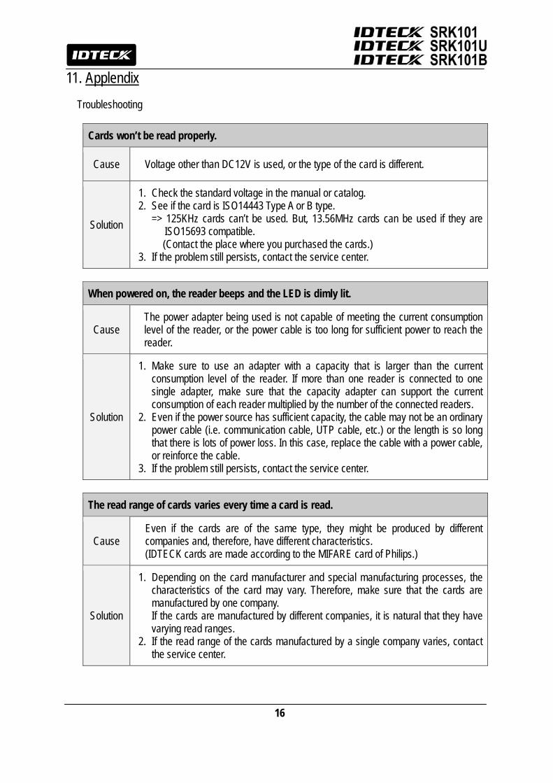
11. Applendix
Troubleshooting
Cards won’t be read properly.
Cause Voltage other than DC12V is used, or the type of the card is different.
Solution
1. Check the standard voltage in the manual or catalog. 2. See if the card is ISO14443 Type A or B type.
=> 125KHz cards can’t be used. But, 13.56MHz cards can be used if they are ISO15693 compatible. (Contact the place where you purchased the cards.)
3. If the problem still persists, contact the service center.
When powered on, the reader beeps and the LED is dimly lit.
Cause The power adapter being used is not capable of meeting the current consumption level of the reader, or the power cable is too long for sufficient power to reach the reader.
Solution
1. Make sure to use an adapter with a capacity that is larger than the current consumption level of the reader. If more than one reader is connected to one single adapter, make sure that the capacity adapter can support the current consumption of each reader multiplied by the number of the connected readers.
2. Even if the power source has sufficient capacity, the cable may not be an ordinary power cable (i.e. communication cable, UTP cable, etc.) or the length is so long that there is lots of power loss. In this case, replace the cable with a power cable, or reinforce the cable.
3. If the problem still persists, contact the service center.
The read range of cards varies every time a card is read.
Cause Even if the cards are of the same type, they might be produced by different companies and, therefore, have different characteristics. (IDTECK cards are made according to the MIFARE card of Philips.)
Solution
1. Depending on the card manufacturer and special manufacturing processes, the characteristics of the card may vary. Therefore, make sure that the cards are manufactured by one company. If the cards are manufactured by different companies, it is natural that they have varying read ranges.
2. If the read range of the cards manufactured by a single company varies, contact the service center.
17
12. FCC Registration Information
FCC REQUIREMENTS PART 15 Caution: Any changes or modifications in construction of this device which are not expressly
approved by the manufacturer for compliance could void the user's authority to operate the equipment.
NOTE: This device complies with Part 15 of the FCC Rules. Operation is subject to the following two conditions; 1. This device may not cause harmful interference, and 2. This device must accept any interference received, including interference that may cause
undesired operation. This equipment has been tested and found to comply with the limits for a Class B Digital Device, pursuant to Part 15 of the FCC Rules. These limits are designed to this equipment generates, uses, and can radiate radio frequency energy and, if not installed and used in accordance with the instructions, may cause harmful interference to radio communications. However, there is no guarantee that interference will not occur in a particular installation. If this equipment does cause harmful interference to radio or television reception, which can be determined by turning the radio or television off and on, the user is encouraged to try to correct interference by one or more of the following measures. 1. Reorient or relocate the receiving antenna. 2. Increase the separation between the equipment and receiver. 3. Connect the equipment into an outlet on another circuit. 4. Consult the dealer or an experienced radio/TV technician for help.
18
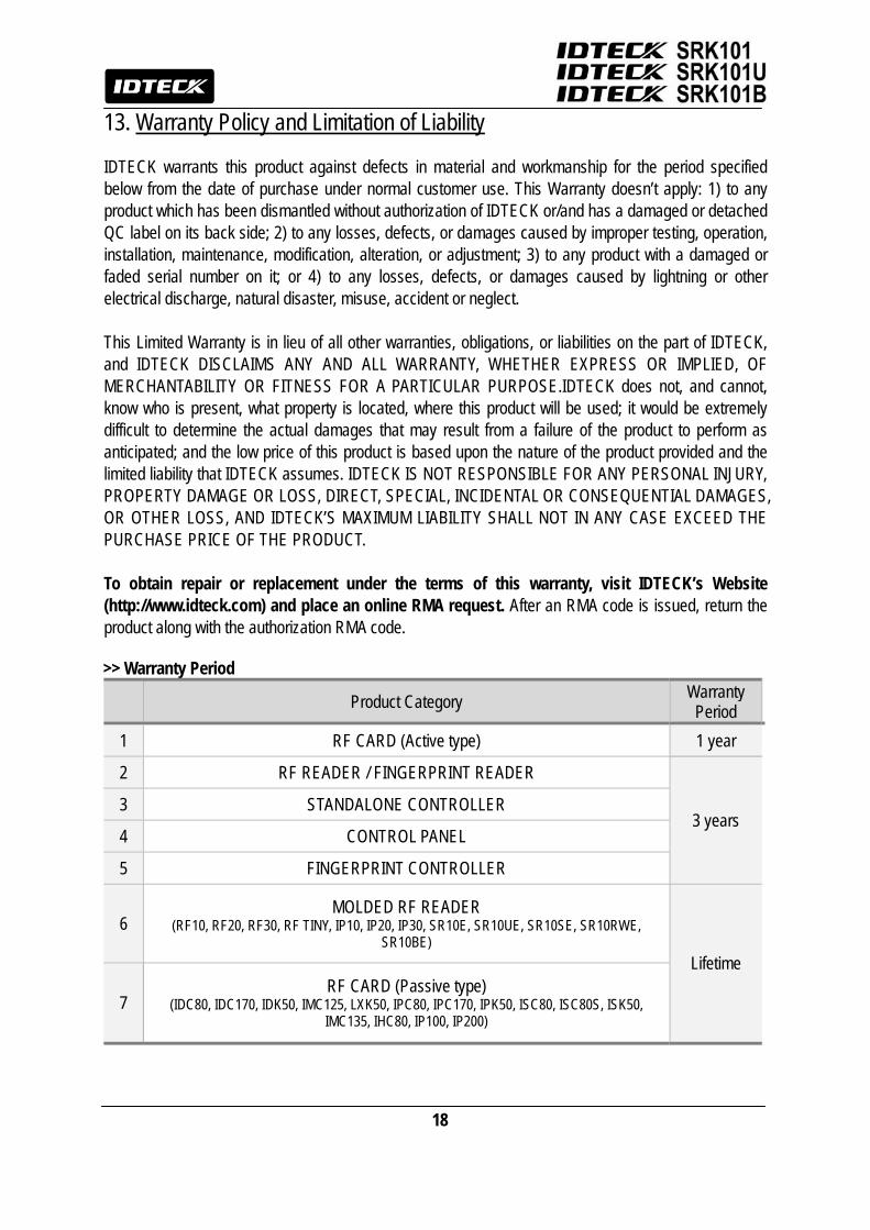
13. Warranty Policy and Limitation of Liability IDTECK warrants this product against defects in material and workmanship for the period specified below from the date of purchase under normal customer use. This Warranty doesn’t apply: 1) to any product which has been dismantled without authorization of IDTECK or/and has a damaged or detached QC label on its back side; 2) to any losses, defects, or damages caused by improper testing, operation, installation, maintenance, modification, alteration, or adjustment; 3) to any product with a damaged or faded serial number on it; or 4) to any losses, defects, or damages caused by lightning or other electrical discharge, natural disaster, misuse, accident or neglect. This Limited Warranty is in lieu of all other warranties, obligations, or liabilities on the part of IDTECK, and IDTECK DISCLAIMS ANY AND ALL WARRANTY, WHETHER EXPRESS OR IMPLIED, OF MERCHANTABILITY OR FITNESS FOR A PARTICULAR PURPOSE.IDTECK does not, and cannot, know who is present, what property is located, where this product will be used; it would be extremely difficult to determine the actual damages that may result from a failure of the product to perform as anticipated; and the low price of this product is based upon the nature of the product provided and the limited liability that IDTECK assumes. IDTECK IS NOT RESPONSIBLE FOR ANY PERSONAL INJURY, PROPERTY DAMAGE OR LOSS, DIRECT, SPECIAL, INCIDENTAL OR CONSEQUENTIAL DAMAGES, OR OTHER LOSS, AND IDTECK’S MAXIMUM LIABILITY SHALL NOT IN ANY CASE EXCEED THE PURCHASE PRICE OF THE PRODUCT. To obtain repair or replacement under the terms of this warranty, visit IDTECK’s Website (http://www.idteck.com) and place an online RMA request. After an RMA code is issued, return the product along with the authorization RMA code. >> Warranty Period
Product Category Warranty Period
1 RF CARD (Active type) 1 year
2 RF READER / FINGERPRINT READER
3 years 3 STANDALONE CONTROLLER
4 CONTROL PANEL
5 FINGERPRINT CONTROLLER
6 MOLDED RF READER
(RF10, RF20, RF30, RF TINY, IP10, IP20, IP30, SR10E, SR10UE, SR10SE, SR10RWE, SR10BE)
Lifetime
7 RF CARD (Passive type)
(IDC80, IDC170, IDK50, IMC125, LXK50, IPC80, IPC170, IPK50, ISC80, ISC80S, ISK50, IMC135, IHC80, IP100, IP200)
19
14. Template

20
The specifications contained in this manual are subject to change without notice at any time.
5F, Ace Techno Tower B/D, 684-1, Deungchon-Dong, Gangseo-Gu, Seoul, 157-030, Korea
Tel : +82-(2)-2659-0055 Fax : +82-(2)-2659-0086
E-mail : [email protected]
MARSR30HK3X MARSR3UHK1X MARSR3BHK3X
Mar. 2009 Copyright IDTECK Co., Ltd.