13243184 validation part 8
TRANSCRIPT
5/17/2018 13243184 Validation Part 8 - slidepdf.com
http://slidepdf.com/reader/full/13243184-validation-part-8 1/143
with laboratory analysis of samples collected at predeter-mined time intervals and processing steps. Thismanufacturing approach tests quality into final products,with resulting suboptimal efficiencies, high levels of rework and scrap, high cost of compliance, and lowlevels of continuous improvement. One major advantageof a shift from the current paradigm to PAT would be thatquality would be built into products.Building quality intothe process may translate into increased product qualityper se, increased regulatory compliance, increasedcapacity and efficiencies, and/or decreased manufac-turing and quality costs.
The PAT approach requires the integratedimplementation of process analyzers, multivariateanalysis tools, process control tools, and continuousimprovement/knowledge management/informationtechnology systems. The complexity of the PAT systemhas resulted in uncertainty with respect to both regulat-ory approach and validation. The FDA’s PAT Guidancefor Industry (1) was an attempt to reduce the uncertaintyand perceived barriers. In addition to the guidancedocument, there has been a series of PAT conferenceschaired by the ACPS and CDER. Although regulatoryand validation uncertainty have been identified as
barriers hindering the adoption of PAT implementationin the pharmaceutical industry, the largest barrier
appears to be the return on investment, especially in theshort-term. The PAT elements such as information tech-nology infrastructure, process analyzers (i.e., NIR),process controls and knowledgeable staff require asubstantial financial investment. This may perhaps bethe limiting factor, especially in times of decreasingshareholder returns and market exclusivity, increasinggeneric competition, decreasing research and discoveryproductivity, and increasing research and discovery costs.
REFERENCES
1. PAT guidance for industry—A framework for innovativepharmaceutical development, manufacturing, and qualityassurance, U.S. Department of Health and HumanServices, Food and Drug Administration, Center forDrug Evaluation and Research (CDER), Center for Veter-inary Medicine (CVM), Office of Regulatory Affairs(ORA), Pharmaceutical cGMPs, September 2004.
2. Balboni ML. Process analytical technology: concepts andprinciples. Pharm Technol 2003; 27:54.
3. Blumenstein J. Pfizer. Regulatory challenges: PATapplication in NDAS. FDA’s Advisory Committee for Phar-maceutical Sciences, Subcommittee on Process AnalyticalTechnologies (PAT), Gaithersburg, MD, June 12–13, 2002.(Accessed May, 2006 at http://www.fda.gov/ohrms/dockets/ac/02/slides/3869S1_02_Blumenstein.ppt)
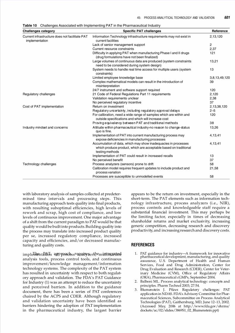
Table 10 Challenges Associated with Implementing PAT in the Pharmaceutical Industry
Challenges category Specific PAT challenges Reference
Current infrastructure does not facilitate PAT
implementation
Information Technology infrastructure requirements may not exist in
current facilities
2,13,120
Lack of senior management support 2
Current resource constraints 2,37
Difficulty in applying PAT when manufacturing Phase I and II drugs
(drug formulations have not been finalized)
121
Large volumes of continuous data are produced (system constraints
need to be considered during system design)
13,21
System needs to handle real time access for multiple users (system
constraints)
13
Limited employee knowledge base 3,8,13,49,120
Complex mathematical models can result in the introduction of
misinterpretation
39
24/7 instrument and software support required 120
Regulatory challenges 21 Code of Federal Regulations Part 11 requirements 2,120
Validation requirements unclear 2,38
No perceived regulatory incentive 37
Cost of PAT implementation Return on investment 2,13,38,120
Regulatory uncertainty, including regulatory approval delays 2–5
For calibration, need a wide range of samples which are within and
outside specifications and which will increase cost
120
Proving equivalency between PAT and traditional methods 38
Industry mindset and concerns Attitude within pharmaceutical industry-no reason to change-statusquo is fine.
13,26
Implementation of PAT into current manufacturing process may
expose deficiencies in manufacturing processes
4,13,41
Accumulation of data, which may show inadequacies in processes
which produce product, which are acceptable based on traditional
testing methods
4,13,41
Implementation of PAT could result in increased recalls 13
No perceived benefit 37
Technology challenges Process analyzers (sensors) prone to drift 58
Calibration model requires frequent updates to include product and
process variation
21,58
Processes are susceptible to unmodelled events 58
45: PROCESS ANALYTICAL TECHNOLOGY AND VALIDATION 601

5/17/2018 13243184 Validation Part 8 - slidepdf.com
http://slidepdf.com/reader/full/13243184-validation-part-8 2/143
4. Clarke PE. CDER aims to improve drug manufacturing.News along the Pike. Center for Drug Evaluation andResearch 2002; 8(July):1.
5. Wechsler J. Modernizing pharmaceutical manufacturing.Pharm Technol N Am 2002; 26:16–24.
6. Chrisholm RS. AstraZeneca. Perspective on process andanalytical validation. FDA’s Advisory Committee forPharmaceutical Sciences, Subcommittee on Process Analy-tical Technologies (PAT), Gaithersburg, MD, February 25,
2002. (Accessed May, 2006 at http://www.fda.gov/ohrms/dockets/ac/02/slides/3841s1_06_chisholm/index.htm)
7. Dean D. PriceWaterhouseCoopers. Pharma manufac-turing—Why there is a need to improve. The role of PAT. FDA’s Advisory Committee for PharmaceuticalSciences, Subcommittee on Process Analytical Tech-nologies (PAT), Gaithersburg, MD February 25, 2002.(Accessed May, 2006 at http://www.fda.gov/ohrms/dockets/ac/02/slides/3841s1_03_Dean/index.htm)
8. McCormick D. PAT survey reflects optimism, uncertainty.Pharm Technol 2005; 29:24.
9. Hammond S. Pfizer. Validation perceptions that may slowPAT development and implementation. Subcommitteefor Pharmaceutical Sciences, Subcommittee on Process
Analytical Technologies (PAT), Rockville, MD, October23, 2002. (Accessed May, 2006 at http://www.fda.gov/ohrms/dockets/ac/02/slides/3901S1_07_Hammond_-files/frame.htm)
10. Rantanen J, Rasanen E, Antikainen O, et al. In-linemoisture measurement during granulation with a four-wavelength near-infrared sensor: an evaluation of process-related variables and a development of non-linear calibration model. Chemom Intell Lab Syst 2001;56:51–8.
11. Hussain AS. Second meeting of FDA/ACPS processanalytical technology: closing remarks. FDA’s AdvisoryCommittee for Pharmaceutical Sciences, Subcommittee onProcess Analytical Technologies (PAT), Gaithersburg, MD,
June 12–13, 2002. (Accessed May, 2006 at http://www.fda.
gov/ohrms/dockets/ac/02/slides/3869S1_09_Hussan-%20Summary/index.htm)
12. Rudd D. GlaxoSmithKline. Product and process develop-ment: an industry perspective. FDA’s AdvisoryCommittee for Pharmaceutical Sciences, Subcommitteeon Process Analytical Technologies (PAT), Gaithersburg,MD, February 25, 2002. (Accessed May, 2006 at http://www.fda.gov/ohrms/dockets/ac/02/slides/3841s1_05_Rudd/index.htm)
13. Neway JO. Filling the void: PAT in a connected manufac-turing environment. Pharm Technol 2003; 27:46–52.
14. Zhou GX, Ge Z, Dorwart J, et al. Determination anddifferentiation of surface and bound water in drugsubstances by near infrared spectroscopy. J Pharm Sci2003; 92:1058–65.
15. Lai CK, Zahari A, Miller B, et al. Nondestructive andon-line monitoring of tablets using light-induced fluor-escence technology. AAPS Pharm Sci Tech 2004; 5:1–10.
16. Bai S, Nayar R, Carpenter JF, et al.Noninvasive determina-tion of protein conformation in the solid state using nearinfrared (NIR) spectroscopy. J Pharm Sci 2005; 94:2030–8.
17. Hammond S. Pfizer. Applications and benefits of PAT.FDA’s Advisory Committee for Pharmaceutical Sciences,Subcommittee on Process Analytical Technologies (PAT),Gaithersburg, MD, February 25, 2002. (Accessed May, 2006at http://www.fda.gov/ohrms/dockets/ac/02/slides/3841s1_02_hammond/index.htm)
18. Hussain AS. Opening remarks. FDA’s AdvisoryCommittee for Pharmaceutical Sciences, Subcommitteeon Process Analytical Technologies (PAT), Gaithersburg,
MD, June 12, 2002. (Accessed May, 2006 at http://www.fda.gov/ohrms/dockets/ac/02/slides/3869S1_01_Hussan-%20Opening%20Remarks/index.htm)
19. Lin Z, Zhou L, Mahajan A, et al. Real-time endpointmonitoring and determination for a pharmaceutical saltformation process with in-line FT-IR spectroscopy.
J Pharm Biomed Anal 2006; 41:99–104.20. Dubois P, Martinez JR, Levillain P. Determination of five
components in a pharmaceutical formulation using near
infrared reflectance spectrophotometry. Analyst 1987;112:1675–9.
21. Dyrby M, Engelsen SB, Norgaard L, et al. Chemometricquantitation of the active substance (containing chn) in apharmaceutical tablet using near-infrared (NIR) transmit-tance and NIR FT-Raman spectra. Appl Spectrosc 2002;56:579–85.
22. Gold TB, Buice RG, Jr., Lodder RA, et al. Determination of extent of formaldehyde-induced crosslinking in hardgelatin capsules by near-infrared spectrophotometry.Pharm Res 1997; 14:1046–50.
23. Gupta A, Peck GE, Miller RW, et al. Nondestructivemeasurements of the compact strength and the particle-size distribution after milling of roller compactedpowders by near-infrared spectroscopy. J Pharm Sci
2004; 93:1047–53.24. Han SM, Faulkner PG. Determination of SB 216469-S
during tablet production using near-infrared reflectancespectroscopy. J Pharm Biomed Anal 1996; 14:1681–9.
25. Harris SC, Walker DS. Quantitative real-time monitoringof dryer effluent using fiber optic near-infrared spec-troscopy. J Pharm Sci 2000; 89:1180–6.
26. Hussain AS. The Subcommittee on Process AnalyticalTechnology (PAT): overview and objectives. FDA’sAdvisory Committee for Pharmaceutical Sciences,Subcommittee on Process Analytical Technologies (PAT),Gaithersburg, MD, February 25, 2002. (Accessed May, 2006at http://www.fda.gov/ohrms/dockets/ac/02/slides/3841s1_01_hussain/index.htm)
27. Kamat MS, Lodder RA, DeLuca PP. Near-infrared spectro-
scopic determination of residual moisture in lyophilizedsucrose through intact glass vials. Pharm Res 1989;6:961–5.
28. Laasonen M, Harmia-Pulkkinen T, Simard C, et al.Development and validation of a near-infrared methodfor the quantitation of caffeine in intact single tablets. AnalChem 2003; 75:754–60.
29. Laasonen M, Harmia-Pulkkinen T, Simard C, et al.Determination of the thickness of plastic sheets used in
blister packaging by near infrared spectroscopy: develop-ment and validation of the method. Eur J Pharm Sci 2004;21:493–500.
30. Laitinen N, Antikainen O, Rantanen J, et al. New perspec-tives for visual characterization of pharmaceutical solids.
J Pharm Sci 2004; 93:165–76.
31. Lonardi S, Newby PJ, Ribeiro D, et al.GlaxoSmithKline.Whydoes PAT need rapid microbiology methods. Subcommitteefor Pharmaceutical Sciences, Subcommittee on ProcessAnalytical Technologies (PAT), Rockville, MD, October 23,2002. (Accessed May, 2006 at http://www.fda.gov/ohrms/dockets/ac/02/slides/3901S1_12_Lonardi_files/frame.htm)
32. O’Neil AJ, Jee RD, Moffat AC. Measurement of thecumulative particle size distribution of microcrystallinecellulose using near infrared reflectance spectroscopy.Analyst 1999; 124:33–6.
33. Otsuka M. Comparative particle size determination of phenacetin bulk powder by using Kubelka-Munk theoryand principal component regression analysis based onnear-infrared spectroscopy. Powder Technol 2004;141:244–50.
602 VIII: COMPUTERIZED SYSTEMS

5/17/2018 13243184 Validation Part 8 - slidepdf.com
http://slidepdf.com/reader/full/13243184-validation-part-8 3/143
34. Sanchez MS, Bertran E, Sarabia LA, et al. Quality controldecisions with near infrared data. Chemom Intell Lab Syst2000; 53:69–80.
35. Tumuluri SVS, Prodduturi S, Crowley MM, et al. The useof near-infrared spectroscopy for the quantitation of adrug in hot-melt extruded films. Drug Dev Ind Pharm2004; 30:505–11.
36. Wang C, Vickers TJ, Mann CK. Direct assay and shelf-lifemonitoring of aspirin tablets using Raman spectroscopy.
J Pharm Biomed Anal 1997; 16:87–94.37. Hussain AS. Office of Pharmaceutical Sciences, CDER,
FDA. ACPS Process Analytical Technology (PAT) Subcom-mittee Meeting #3 Opening Remarks. Subcommitteefor Pharmaceutical Sciences, Subcommittee on ProcessAnalytical Technologies (PAT), Rockville, MD, October23, 2002. (Accessed May, 2006 at http://www.fda.gov/ohrms/dockets/ac/02/slides/3901S1_01_Hussain_files/frame.htm)
38. Shah DN. Aventis Pharmaceuticals. Regulatory chal-lenges: post-approval PAT applications. FDA’s AdvisoryCommittee for Pharmaceutical Sciences, Subcommitteeon Process Analytical Technologies (PAT), Gaithersburg,MD, June 12–13, 2002. (Accessed May, 2006 at http://www.fda.gov/ohrms/dockets/ac/02/slides/3869S1_03_
Shah/index.htm)39. Workman J. Kimberly-Clark Corp. Chemometrics and
PAT: an opinion on current status and recommendationsfor the future. FDA’s Advisory Committee for Pharma-ceutical Sciences, Subcommittee on Process AnalyticalTechnologies (PAT), Gaithersburg, MD, February 25,2002. (Accessed May, 2006 at http://www.fda.gov/ohrms/dockets/ac/02/slides/3841s1_08_workman/index.htm)
40. Watson DJ, Dowdy ED, DePue JS, et al. Development of asafe and scalable oxidation process for the preparation of 6-hydroxybuspirone: application of in-line monitoring forprocess ruggedness and product quality. Org Process ResDev 2004; 8:616–23.
41. Avallone H. Johnson & Johnson. Development/compli-ance issues (tablets). FDA’s Advisory Committee forPharmaceutical Sciences, Subcommittee on ProcessAnalytical Technologies (PAT), Gaithersburg, MD, June12–13, 2002. (Accessed May, 2006 at http://www.fda.gov/ohrms/dockets/ac/02/slides/3869S1_04_Avallone.ppt)
42. Herkert T, Prinz H, Kovar KA. One hundred percentonline identity check of pharmaceutical products bynear-infrared spectroscopy on the packaging line. Eur
J Pharm Biopharm 2001; 51:9–16.43. Frake P, Greenhalgh D, Grierson SM, et al. Process control
and end-point determination of a fluid bed granulation byapplication of near infra-red spectroscopy. Int J Pharm1997; 151:75–80.
44. Morisseau KM, Rhodes CT. Near infrared spectroscopy as
a nondestructive alternative to conventional tablet hard-ness testing. Pharm Res 1997; 14:108–11.45. Fevotte G, Calas J, Puel F, et al. Applications of NIR
spectroscopy to monitoring and analyzing the solid stateduring industrial crystallization process. Int J Pharm 2004;273:159–69.
46. Skibsted ETS, Boelens HFM, Westerhuis JA, et al. Simpleassessment of homogeneity in pharmaceutical mixingprocesses using a near-infrared reflectance probe andcontrol charts. J Pharm Biomed Anal 2006; 41:26–35.
47. Cui X, Zhang Z, Ren Y, et al. Quality control of thepowder pharmaceutical samples of sulfaguanidine byusing NIR reflectance spectrometry and temperature-constrained cascade correlation networks. Talanta 2004;64:943–8.
48. Woo YA, Lim HR, Kim HJ, et al. Determination of hydrogen peroxide concentration in antiseptic solutionsusing portable near-infrared system. J Pharm BiomedAnal 2003; 33:1049–57.
49. Hussain AS. FDA’s Advisory Committee for Pharmaceu-tical Sciences, The ACPS’s Process Analytical TechnologySubcommittee, Rockville, MD, November 28, 2001.(Accessed May, 2006 at http://www.fda.gov/ohrms/dockets/ac/01/slides/3804s1_02_hussain/sld001.htm)
50. Andre M. Multivariate analysis and classification of thechemical quality of 7-aminocephalosporanic acid usingnear-infrared reflectance spectroscopy. Anal Chem 2003;75:3460–7.
51. Blanco M, Romero MA. Near-infrared libraries in thepharmaceutical industry: a solution for identity confir-mation. Analyst 2001; 126:2212–7.
52. Lonardi S, Viviani R, Mosconi L, et al. Drug analysis bynear-infra-red reflectance spectroscopy. Determination of the active ingredient and water content in antibioticpowders. J Pharm Biomed Anal 1989; 7:303–8.
53. Plugge W, van der Vlies C. Near-infrared spectroscopy asan alternative to assess compliance of ampicillin trihy-drate with compendia1 specifications. J Pharm BiomedAnal 1993; 11:435–42.
54. Blanco M, Coello J, Iturriaga H, et al. Critical review: near-infrared spectroscopy in the pharmaceutical industry.Analyst 1998; 123:135R–50.
55. Workman J, Jr., Veltkamp DJ, Doherty S, et al. Processanalytical chemistry. Anal Chem 1999; 71:121R–80.
56. Workman J, Jr., Creasy KE, Doherty S, et al. Processanalytical chemistry. Anal Chem 2001; 73:2705–18.
57. Blanco M, Villarroya I. NIRspectroscopy: a rapid-responseanalytical tool. Trends Anal Chem 2002; 21:240–50.
58. Lavine BK, Workman J, Jr. Chemometrics. Anal Chem2002; 74:2763–70.
59. Workman J, Jr., Koch M, Veltkamp DJ. Process analyticalchemistry. Anal Chem 2003; 75:2859–76.
60. Yu LX, Lionberger RA, Raw AS, et al. Applications of process analytical technology to crystallization processes.
Adv Drug Del Rev 2004; 56:349–69.61. Abrahamsson C, Johansson J, Sparen A, et al. Comparison
of different variable selection methods conducted on NIRtransmission measurements on intact tablets. ChemomIntell Lab Syst 2003; 69:3–12.
62. Airaksinen S, Luukkonen P, Jorgensen A, et al. Effects of excipients on hydrate formation in wet masses containingtheophylline. J Pharm Sci 2003; 92:516–28.
63. Betz G, Burgin PJ, Leuenberger H. Power consumptionmeasurement and temperature recording during granula-tion. Int J Pharm 2004; 272:137–49.
64. Blanco M, Eustaquio A, Gonzalez JM, et al. Identificationand quantitation assays for intact tablets of two relatedpharmaceutical preparations by reflectance near-infraredspectroscopy: validation of the procedure. J Pharm
Biomed Anal 2000; 22:139–48.65. Blanco M, Villar A. Development and validation of a
method for the polymorphic analysis of pharmaceuticalpreparations using near infrared spectroscopy. J Pharm Sci2003; 92:820–3.
66. Yoon WL, Jee RD, Charvill A, et al. Application of near-infrared spectroscopy to the determination of the sites of manufacture of proprietary products. J Pharm BiomedAnal 2004; 34:933–44.
67. Blanco M, Romero MA, Alcala M. Strategies forconstructing the calibration set for a near infrared spectro-scopic quantitation method. Talanta 2004; 64:597–602.
68. Clarke F. Extracting process-related information frompharmaceutical dosage forms using near infraredmicroscopy. Vib Spectrosc 2004; 34:25–35.
45: PROCESS ANALYTICAL TECHNOLOGY AND VALIDATION 603

5/17/2018 13243184 Validation Part 8 - slidepdf.com
http://slidepdf.com/reader/full/13243184-validation-part-8 4/143
69. Davis TD, Morris KR, Huang H, et al. In situ monitoring of wet granulation using online x-ray powder diffraction.Pharm Res 2003; 20:1851–7.
70. Fountain W, Dumstorf K, Lowell AE, et al. Near-infraredspectroscopy for the determination of testosterone in thin-film composites. J Pharm Biomed Anal 2003; 33:181–9.
71. Jorgensen AN, Luukkonen P, Rantanen J, et al. Compari-son of torque measurements and near-infrared spectro-scopy in characterization of a wet granulation process.
J Pharm Sci 2004; 93:2232–43.72. Laasonen M, Rantanen J, Harmia-Pulkkinen T, et al. Nearinfrared reflectance spectroscopy for the fast identificationof PVC-based films. Analyst 2001; 126:1122–8.
73. Ritchie GE, Roller RW, Ciurczak EW, et al. Validation of anear-infrared transmission spectroscopic procedure. PartB: application to alternate content uniformity and releaseassay methods for pharmaceutical solid dosage forms.
J Pharm Biomed Anal 2002; 29:159–71.74. Blanco M, Coello J, Iturriaga H, et al. Determination of
absorbic acid in pharmaceutical preparations by nearinfrared reflectance spectroscopy. Talanta 1993; 40:1671–6.
75. Blanco M, Coello J, Iturriaga H, et al. Control analysis of apharmaceutical preparation by near-infrared reflectancespectroscopy. A comparative study of a spinning module
and fibre optic probe. Anal Chim Acta 1994; 298:183–91.76. Blanco M, Coello J, Iturriaga H, et al. Determination of water in ferrous lactate by near infrared reflectance spec-troscopy with a fibre-optic probe. J Pharm Biomed Anal1997; 16:255–62.
77. Gottfries J, Depui H, Fransson M, et al. Vibrationalspectrometry for the assessment of active substance inmetoprolol tablets: a comparison between transmissionand diffuse reflectance near-infrared spectrometry.
J Pharm Biomed Anal 1996; 14:1495–503.78. Last IR, Prebble KA. Suitability of near-infrared methods
for the determination of moisture in a freeze-dried injec-tion product containing different amounts of the activeingredient. J Pharm Biomed Anal 1993; 11:1071–6.
79. Higgins JP, Arrivo SM, Thurau G, et al. Spectroscopicapproach for on-line monitoring of particle size duringthe processing of pharmaceutical nanoparticles. AnalChem 2003; 75:1777–85.
80. Watano S, Numa T, Koizumi I, et al. Feedback control inhigh shear granulation of pharmaceutical powders. Eur
J Pharm Biopharm 2001; 52:337–45.81. Watano S, Numa T, Miyanami K, et al. A fuzzy control
system of high shear granulation using image processing.Powder Technol 2001; 115:124–30.
82. Andersson M, Folestad S, Gottfries J, et al. Quantitativeanalysis of film coating in a fluidized bed process byin-line NIR spectrometry and multivariate batch cali-
bration. Anal Chem 2000; 72:2099–108.83. Broad NW, Jee RD, Moffat AC, et al. Non-invasive
determination of ethanol, propylene glycol and water in amulti-component pharmaceutical oral liquid by direct
measurement through amber plastic bottles using Fouriertransform near-infrared spectroscopy. Analyst 2000;125:2054–8.
84. Rantanen J, Rasanen E, Tenhunen J, et al. In-line moisturemeasurement during granulation with a four-wavelengthnear infrared sensor: an evaluation of particle size and
binder effects. Eur J Pharm Biopharm 2000; 50:271–6.85. Kirsch JD, Drennen JK. Nondestructive tablet hardness
testing by near-infrared spectroscopy: a new and robustspectral best-fit algorithm. J Pharm Biomed Anal 1999;19:351–62.
86. Eustaquio A, Blanco M, Jee RD, et al. Determination of Paracetamol in intact tablets by use of near infraredtransmittance spectroscopy. Anal Chim Acta 1999;383:283–90.
87. Blanco M, Coello J, Eustaquio A, et al. Analytical control of pharmaceutical production steps by near infrared reflec-tance spectroscopy. Anal Chim Acta 1999; 392:237–46.
88. Blanco M, Coello J, Eustaquio A, et al. Development andvalidation of a method for the analysis of a pharmaceuticalpreparation by near-infrared diffuse reflectance spec-troscopy. J Pharml Sci 1999; 88:551–6.
89. Blanco M, Coello J, Iturriaga H, et al. Development andvalidation of a near infrared method for the analytical
control of a pharmaceutical preparation in three steps of the manufacturing process. Fresenius J Anal Chem 2000;368:534–9.
90. Gupta A, Peck GE, Miller RW, et al. Real-time near-infrared monitoring of content uniformity, moisturecontent, compact density, tensile strength, and Young’smodulus of roller compacted powder blends. J Pharm Sci2005; 94:1589–97.
91. Lai CK, Cooney CC. Application of a fluorescence sensorfor miniscale on-line monitoring of powder mixingkinetics. J Pharm Sci 2004; 93:60–70.
92. Moffat AC, Trafford AD, Jee RD, et al. Meeting of theInternational Conference on Harmonisation’s Guidelineson Validation of Analytical Procedures: quantification asexemplified by a near-infrared reflectance assay of para-
cetamol in intact tablets. Analyst 2000; 125:1341–51.93. El-Hagrasy AS, D’Amico F, Drennen JK, III. A process
analytical technology approach to near-infrared processcontrol of pharmaceutical powder blending. Part I:D-optimal design for characterization of powder mixingand preliminary spectral data evaluation. J Pharm Sci2006; 95:392–406.
94. El-Hagrasy AS, Delgado-Lopez M, Drennen JK, III. Aprocess analytical technology approach to near-infraredprocess control of pharmaceutical powder blending: PartII: qualitative near-infrared models for prediction of blendhomogeneity. J Pharm Sci 2006; 95:407–21.
95. El-Hagrasy AS, Drennen JK, III. A process analyticaltechnology approach to near-infrared process control of pharmaceutical powder blending. Part III: quantitativenear-infrared calibration for prediction of blend homogen-eity and characterization of powder mixing kinetics.
J Pharm Sci 2006; 95:422–34.96. Gupta A, Peck GE, Miller RW, et al. Influence of ambient
moisture on the compaction behavior of microcrystallinecellulose powder undergoing uni-axial compression androller-compaction: a comparative study using near-infra-red spectroscopy. J Pharm Sci 2005; 94:2301–13.
97. Bai SJ, Rani M, Suryanarayanan R, et al. Quantification of glycine crystallinity by near-infrared (NIR) spectroscopy.
J Pharm Sci 2004; 93:2439–47.98. Seyer JJ, Luner PE, Kemper MS. Application of diffuse
reflectance near-infrared spectroscopy for determinationof crystallinity. J Pharm Sci 2004; 89:1305–16.
99. Lai CK, Holt D, Leung JC, et al. Real-time and non-invasive monitoring of dry powder blend homogeneity.AIChE J 2001; 47:2618–22.
100. Johansson J, Pettersson S, Folestad S. Characterization of different laser irradiation methods for quantitative Ramantablet assessment. J Pharm Biomed Anal 2005; 39:510–6.
101. Cogdill RP, Anderson CA, Delgado-Lopez M, et al. Processanalytical technology case study Part I: feasibility studiesfor quantitative near-infrared method development.AAPS Pharm Sci Tech 2005; 6:E262–72.
102. Cogdill RP, Anderson CA, Delgado M, et al. Processanalytical technology case study: Part II. Developmentand validation of near-infrared calibrations in support of a process analytical technology application for real-timerelease. AAPS Pharm Sci Tech 2005; 6:E273–83.
604 VIII: COMPUTERIZED SYSTEMS
5/17/2018 13243184 Validation Part 8 - slidepdf.com
http://slidepdf.com/reader/full/13243184-validation-part-8 5/143
103. Cogdill RP, Anderson CA, Delgado M, et al. Process analy-tical technology case study, Part III: calibration monitoringand transfer. AAPS Pharm Sci Tech 2005; 6:E284–97.
104. Hausman DS, Cambron RT, Sakr A. Application of on-lineRaman spectroscopy for characterizing relationships
between drug hydration state and tablet physical stability.Int J Pharm 2005; 299:19–33.
105. Islam MT, Rodrıguez-Hornedo N, Ciotti S, et al. Thepotential of Raman spectroscopy as a process analytical
technique during formulations of topical gels and emul-sions. Pharm Res 2004; 21:1844–51.106. Johansson J, Pettersson S, Taylor LS. Infrared imaging of
laser-induced heating during Raman spectroscopy of pharmaceutical solids. J Pharm Biomed Anal 2002;30:1223–31.
107. Kontoyannis CG. Quantitative determination of CaCO3
and glycine in antacid tablets by laser Raman spec-troscopy. J Pharm Biomed Anal 1995; 13:73–6.
108. Langkilde FW, Sjoblom J, Tekenbergs-Hjelte L, et al. Quan-titative FT-Raman analysis of two crystal forms of apharmaceutical compound. J Pharm Biomed Anal 1997;15:687–96.
109. Szostak R, Mazurek S. Quantitative determination of acetylsalicylic acid and acetaminophen in tablets byFT-Raman spectroscopy. Analyst 2002; 127:144–8.
110. Taylor LS, Zografi G. The quantitative analysis of crystal-linity using FT-Raman spectroscopy. Pharm Res 1998;15:755–61.
111. Shabushnig JG. Pharmacia Corporation. Process analyticaltechnology: an industry perspective. FDA’s AdvisoryCommittee for Pharmaceutical Sciences, Subcommitteeon Process Analytical Technologies (PAT), Gaithersburg,MD, February 25, 2002. (Accessed May, 2006 at http://www.fda.gov/ohrms/dockets/ac/02/slides/3841s1_04_Shabushnig_files/frame.htm)
112. Clevett KJ. Process analytical chemistry—industryperspectives—trends in applications and technology.Process Control Qual 1994; 6:81–90.
113. Sinsheimer JE, Poswalk NM. Pharmaceutical applicationsof the near infrared determination of water. J Pharm Sci1968; 57:2007–10.
114. Ryder AG, O’Conner GM, Glynn TJ. Quantitative analysisof cocaine in solid mixtures using Raman spectroscopyand chemometric methods. J Raman Spectrosc 2000;
31:221–7.115. Clarke FC, Jamieson MJ, Clark DA, et al. Chemical imagefusion. The synergy of FTNIR and Raman mappingmicroscopy to enable a more complete visualization of pharmaceuticalformulations.Anal Chem2001;73:2213–20.
116. Chang H, Huang P. Thermo-Raman spectroscopy. RevAnal Chem 2001; 20:207–38.
117. Ghule A, Baskaran N, Murugan R, Chang H. Phasetransformation studies of Na3PO4 by thermo-Raman andconductivity measurements. Solid State Ionics 2003;161:291–9.
118. de Jager H-J, Prinsloo L. The dehydration of phosphatesmonitored by DSC/TGA and in situ Raman spectroscopy.Thermochim Acta 2001; 376:187–96.
119. 2006 USPC, Inc. Official 4/1/06-7/31/06 General Chap-ters:!1119O Near-Infrared Spectrophotometry.
120. GlaxoSmithKline. Perspectives in chemometrics. Experi-ence from GlaxoSmithKline. FDA’s Advisory Committeefor Pharmaceutical Sciences, Subcommittee on ProcessAnalytical Technologies (PAT), Gaithersburg, MD,February 25, 2002. (Accessed May, 2006 at http://www.fda.gov/ohrms/dockets/ac/02/slides/3841s1_09_walker/sld001.htm)
121. Bush L. New CGMP plant at Purdue University offersmultiple benefits. Pharm Technol 2003; 27:22.
45: PROCESS ANALYTICAL TECHNOLOGY AND VALIDATION 605

5/17/2018 13243184 Validation Part 8 - slidepdf.com
http://slidepdf.com/reader/full/13243184-validation-part-8 6/143

5/17/2018 13243184 Validation Part 8 - slidepdf.com
http://slidepdf.com/reader/full/13243184-validation-part-8 7/143
46
Computerized Systems Validation
Saeed TafreshiIntelitec Corporation, Irvine, California, U.S.A.
The concept of validation was developed in the 1970s andis widely credited to Ted Byers who was then AssociateDirector of Compliance at the U.S. FDA. The concept wasfocused on:
Establishing documented evidence which provides ahigh degree of assurance that a specific process willconsistently produce a product meeting its predeter-mined specifications and quality attributes.
This concept continues to be followed, with somemodifications, by the various authorities regulating GMParound the world. This definition also has been adoptedfor the validation business, manufacturing and labora-tory computer systems. The need to validate computersystems formally began in 1979 when the U.S.A. intro-duced GMP regulatory legislation which specificallyreferred to automation equipment. GMP is enforced bynational regulatory authorities who can prevent the saleof a product in their respective country if they consider itsmanufacture not to be GMP compliant. Validation forGMP is a license-to-operate issue.
Over the last three decades, the manufacturingindustry has increasingly used computer systems to
control manufacturing processes for improved per-formance and product quality. This policy is oftenembedded in corporate strategy. Computer systems,however, by the nature of their complexity are susceptibleto development and operational deficiencies which canadversely affect their control ability and effect productsafety, quality and efficacy. Common examples of suchdeficiencies include poor specification capture, designerrors, poor testing and poor maintenance practice.
The potentially devastating outcome of GMPnoncompliance of computer systems was demonstratedin 1988 when deficient software in data managementsystem controlling a blood bank could have led to the
issue of AIDS-infected blood. Additionally, computer
systems can endanger public health through the manu-facture and release of drug products with deficientquality attributes.
The first widely publicized FDA citation forcomputer validation noncompliance occurred in 1985;however, as early as 1982, the FDA was publicly statingthat it was “nervous” if computer systems were usedwithout being validated. In 1983, the FDA issued theGuide to Inspection of Computerized Systems in DrugProcessing, Technical Report, Reference Materials andTraining Aids for Investigators which became known asthe “Blue Book.” This publication guided inspectors onwhat to accept as validation evidence for computersystems. The Blue Book formally introduced the antici-pation of a life-cycle approach to validation. The aim wasto build in quality (QA) rather than rely on testing inquality (quality control).
Responding to the FDA’s proactive position oncomputer systems validation, the PMA formed aComputer Systems Validation Committee to representand coordinate the industry’s viewpoint. The resultswere a joint FDA/PMA Conference in 1984 discussingcomputer systems validation and in the following year
the publication of an industry perspective. The publi-cation presented an approach for validation for both newand existing computer systems. GMP legislation isunusual in that it is equally applied to new productionfacilities and to production facilities built entirely orpartially before the legislation (including amendments)was enforced.
Throughout the 1980s, computer systems validationwas debated primarily in the U.S.A. Ken Chapmanpublished a paper covering this period during whichthe FDA gave advice on the following GMP issues:& Input/output checking& Batch records& Applying GMP to hardware and software
& Supplier responsibility& Application software inspection& FDA investigation of computer systems& Software development activities
In addition, since the end of 1980s, the FDA and thepharmaceutical industry have debated the GMP require-ments and the practicalities of electronic signatures. Aresolution was achieved which became the FDA’sproposed regulation.
Complementing the U.S. GMP guidance, theEuropean Commission and authorities in Australia bothissued GMP codes of practice in 1989 and 1990 respect-ively. The European code known as the “Orange Guide”was later issued in 1991 as a Directive superseding
Abbreviations used in this chapter: AZT, International association forPharmaceutical Technology; cGMP, current good manufacturingpractice; CRT, cathode ray tube; DQ, design qualification; EU,European Union; FAT, factory acceptance test; FDA, Food andDrug Administration; GAMP, good automated manufacturingpractice; GMP, good manufacturing practice; IQ, installation qualifi-cation; ISPE, International Society of Pharmaceutical Engineering;MCA, Medicines Control Agency; OQ, operational qualification;PDA, Parenteral Drug Association; PLC, programmable logiccontroller; PMA, Pharmaceutical Manufactures Association; PQ,performance qualification; QA, quality assurance; SCADA, super-visory control and data acquisition; SQ, system qualification orspecification qualification; URS, user requirements specification.

5/17/2018 13243184 Validation Part 8 - slidepdf.com
http://slidepdf.com/reader/full/13243184-validation-part-8 8/143
member state GMP legislation and included an annexcovering computerized systems.
In most countries, GMP has been interpretive and toprosecute a pharmaceutical manufacturing a court must be convinced that the charges reflect the intent to floutgoverning legislation. In the U.S.A., however, a courtdeclaratory judgment determined supplementary GMPinformation to be substantive. The net effect was that the
FDA’s advisory opinions became binding on the Agency.In August of 1990, the FDA announced that it no longerconsidered advisory opinions binding on the groundsthat Counsel considered such restrictions unconstitu-tional. Hence, the FDA interpretation of the regulationsin Compliance Policy Guides, Guide to Investigators,and other publications by FDA authors becamenonbinding.
Computer systems validation also became a highprofile industry issue in Europe in 1991 when severalEuropean manufacturers and products were temporarily banned from the U.S.A. for computer systems noncom-pliance. The computer systems in question includedautoclave PLCs and SCADA systems. The position of
the FDA was clear; the manufacturer had failed to satisfytheir “concerns” that computer systems should:& Perform accurately and reliably& Be secure from unauthorized or inadvertent changes& Provide for adequate documentation of the process
The manufacturers thought they had satisfiedthe requirements of the existing GMP legislations, butthey had not satisfied the FDA’s expectations of GMP.Hence the adoption of cGMP to signify the latest under-standing of the validation practices and standardsexpected by the regulatory authorities began.
In 1991, the U.K. Pharmaceutical IndustryComputer Systems Validation Forum (known as theU.K. FORUM) was established to facilitate the exchangeof validation knowledge and the development of astandard industry guide for computer systems vali-dations. At this time suppliers were on the wholestruggling to understand and implement the variousinterpretations and requirements of GMP presented bythe manufacturers. ISO 9000 and TickIT accreditation forquality management provided a good basis for vali-dation, but it does not fully satisfy GMP requirements.Then, the U.K. FORUM’s guide came to fruition and waslaunched as a first draft within the U.K. The guide is oftenreferred to as the GAMP guide.
Meanwhile two experienced GMP regulatoryinspectors, Ron Tetzlaff and Tony Trill, published
papers respectively presenting the FDA’s and U.K.’sMCA inspection practice for computer systems. Thesepapers presented a comprehensive perspective on thecurrent validation expectations of GMP regulatoryauthorities. Topics covered included:& Life-cycle approach& Quality management& Procedures& Training& Validation protocols& Qualification evidence& Change control& Audit trail& Ongoing evaluation
The pharmaceutical industry in search of a commonapproach to computer systems validation began incor-porating these topics. Nevertheless, the FDA and MCAcontinue to encounter instances of noncompliance prac-tice based on:& Incomplete documents& Insufficient detail in documents& Missing documentary evidence
There was a clear need for guidance and standardson computer systems validation and early in 1995 therewere four milestones of significance to practitioners:& The U.S.A. proposed new GMP legislation affecting
electronic records and electronic signatures.& After 16 years the U.S.A. amended its legislation
affecting computer validation, making a minorconcession concerning the degree of input/outputvalidation required for reliable computer systems.
& The U.S. PDA presented a manufacturer’s guide tocomplement the PMA life cycle.
& The U.K. FORUM issued a revised draft of theirsupplier guide for European comment.
These initiatives helped the manufacturers and
suppliers meet the challenge to validate computersystems effectively and efficiently. The initiatives whichfurther clarified the requirements of validation included:& The U.K. FORUM’s investigation into the benefits of
supplier audits shared by a number of participant manufacturers.
& The German APV (Information Technology Section)guide to Annex 11 of the European United GMPDirective regarding computerized systems.
& The German GMA Committee 5.8 and NAMURCommittee 1.9 joint working group’s recommen-dations for computer systems validation.
& The coordination of the German initiatives with theU.K. FORUM supplier guide, and possibly the U.S.
PDA manufacturer’s guide, as announced at the ISPEcomputer validation seminar in Amsterdam in Marchof 1995.
What is clear to date is the mutual benefit of regulators, manufacturers and suppliers workingtogether towards a common GMP goal. GMP, whilefacilitating improvements to manufacturing per-formance, also is integral to the continuing highstanding of the pharmaceutical industry.
In order for the industry to follow a common pathin complying with the cGMP guidelines related tocomputer control systems, there is a need to understandthe basics of proper system development and considerthe overall cost into building a true business case. In
doing so, it is necessary to follow the stages in sequencefor the validation of a computerized control system toFDA requirements and their relationship to the develop-ment and implementation stages of an automationproject.
The Quality System regulation requires that “whencomputers or automated data processing systems areused as part of production or the quality system, themanufacturer shall validate computer software for itsintended use according to an established protocol.” Thishas been a regulatory requirement for GMP since 1978.
In addition to the above validation requirement,computer systems that implement part of a regulatedmanufacturer’s production processes or quality system
608 VIII: COMPUTERIZED SYSTEMS

5/17/2018 13243184 Validation Part 8 - slidepdf.com
http://slidepdf.com/reader/full/13243184-validation-part-8 9/143
(or that are used to create and maintain records required by any other FDA regulation) are subject to the ElectronicRecords, Electronic Signatures regulation. This regulationestablishes additional security, data integrity, and vali-dation requirements when records are created ormaintained electronically. These additional Part 11requirements should be carefully considered andincluded in system requirements and software require-
ments for any automated record keeping systems. Systemvalidation and software validation should demonstratethat all Part 11 requirements have been met.
Computers and automated equipment are usedextensively throughout Pharmaceutical, Biotech,Medical Device, and Medical Gas industries in areassuch as design, laboratory testing and analysis, productinspection and acceptance, production and processcontrol, environmental controls, packaging, labeling,traceability, document control, complaint management,and many other aspects of the quality system. Increas-ingly, automated plant floor operations have involvedextensive use of embedded systems in& PLCs&
digital function controllers& statistical process control& supervisory control and data acquisition& robotics& human–machine interfaces& input/output devices& computer operating systems
Computerized operations are now common in FDAregulated industries. Small “minicomputer” systems are being used, sometimes in conjunction with larger compu-ters, to control batching operations, maintain formulafiles and inventories, monitor process equipment, checkequipment calibration, etc. The medical device industry ispresently utilizing automatic test sets controlled by
computers. In this application the computer is reliedupon to make the decision as to whether a particulartest parameter is within a specific tolerance. The operatordoes not see the values of the parameters measured, butmerely receives a green or red light indicating a go/no gosituation. Products are accepted or rejected on this basis.In order to evaluate and/or report the adequacy of anycomputer-controlled processes or tests, the basics of computer construction and operation must be under-stood. The entire computer control system has beensimplified as follows.
A computer is a machine and like all othermachines is normally used because it performsspecific tasks with greater accuracy and more efficiency
than people. Computers accomplish this by having thecapacity to receive, retain, and give up large volumes of data and process it in a very short time. An under-standing of computer operation, and the ability to use acomputer, does not require a detailed knowledge of eitherelectronics or the physical hardware construction. Anoverall view of the computer organization with emphasison function is sufficient.
There are basically two types of computers, analogand digital. The analog computer does not computedirectly with numbers. It accepts electrical signals of varying magnitude (analog signals) which in practicaluse are analogous to or represent some continuousphysical magnitude such as pressure, temperature, etc.
Analog computers are sometimes used for scientific,engineering and process-control purposes. In themajority of industry applications used today, analogvalues are converted to digital form by an analog-to-digital converter and processed by digital computers.
The digital computer is the general use computerused for manipulating symbolic information. In mostapplications the symbols manipulated are numbers and
the operations performed on the symbols are the stan-dard arithmetical operations. Complex problem solvingis achieved by basic operations of addition, subtraction,multiplication and division.
A digital computer is designed to accept and storeinstructions (program), accept information (data) andprocess the data as specified in the program anddisplay the results of the processing in a selectedmanner. Instructions and data are in coded form thecomputer is designed to accept. The computer performsautomatically and in sequence according to the program.
The computer is a collection of interconnectedelectromechanical devices (hardware) directed by acentral control unit. The central control unit is the
controlling device that supervises the sequence of activi-ties that take place in all parts of the computer. Classically,the hardware consists of the mainframe (computer) forcomputation, storage and control, and peripheral devices(input–output devices) for entering raw data and printingor displaying the output. Input data may be entered intothe computer by teletypewriters, magnetic tape, punchedtape, card readers, etc. Output may be displayed in theform of a hardcopy printout, magnetic tape, CRT, etc. Thetwo units of input and output are often joined andreferred to as input/output or simply I/O. A computerterminal with a CRT display is an example of a combinedInput/Output device.
Equally important as hardware in the effective use
of the digital computer is the software. The numerouswritten programs and/or routines that dictate the processsequence the computer will follow are called software. Acomputer can be programmed to do almost any problemthat can be “defined.” Defined means that the solution of a problem must be reduced to a series of steps that can bewritten as a series of computer instructions. In otherwords, the individual steps of the problem must be setup, including the desired level of accuracy, prior to thecomputer processing and solving the problem. Thecomputer must be directed or commanded by a preciselystated set of commands or program. Until a program isprepared and stored in the computer memory, thecomputer knows absolutely nothing, not even how to
receive input data. The accuracy and validation of theprogram is one of the most important aspects of computer control.
Physical quantities are especially adaptive to binarydigital techniques because most physical quantities can be expressed as two states: switches are on or off, aquantity level is above or below a set value, holes incards are punched or not punched, electrical voltage orcurrent is positive or negative or above or below a presetvalue. For such applications as process control, the digitalcomputer makes decisions by comparing input data to apredetermined value. The computer takes a course of action dependent on whether the input data is greaterthan, equal to, or less than the predetermined value.
46: COMPUTERIZED SYSTEMS VALIDATION 609

5/17/2018 13243184 Validation Part 8 - slidepdf.com
http://slidepdf.com/reader/full/13243184-validation-part-8 10/143
The predetermined value and course of action thecomputer follows is in the form of a program stored inthe computer memory. So, actually the computer does notmake decisions, but merely follows written programinstructions. A printout or display of the actual valuesmeasured may be included as a part of the program.Verification of proper computer operation may be accom-plished in this example by applying known inputs,
greater, equal to and less than the predetermined valueand subsequently reviewing the results.When validating a computer control system,
particular attention must be made to following of estab-lished procedures and the documentation requiredduring each stage to ensure that proper and sufficientdocumented evidence is provided to support validationinspection by the FDA.
The FDA has issued two validation definitionswhich state the following:1. “Establishing documented evidence that a system
does what it is designed to do.”2. “Establishing documented evidence which provides
a high degree of assurance that a specific process will
consistently produce a product meeting its predeter-mined specifications and quality attributes.”
The FDA audits against compliance with cGMPrequirements. Rigid procedures are required to befollowed and those procedures must generate sufficientdocumentation to ensure that traceability and account-ability of information (an audit trail) is maintained.
The FDA does not provide certification for acompany and its procedures nor does it approve whatdocumentation should be produced. The company isresponsible for demonstrating that procedures arefollowed and associated documentation generated tosupport the manufacture of the company’s products.
The FDA’s position was made clear in the following
statement made by Ronald Tetzlaff (when he wasemployed by the FDA) in Pharmaceutical Technology,April 1992, which states that “Unless firms have docu-mented evidence to ensure the proper performance of avendor’s software, the FDA cannot consider the auto-mated system to be validated.”
Therefore it is important that companies haveapproved Quality Systems in place that ensure thatprocedures are followed and an audit trail is maintained.
COMPUTERIZED SYSTEM VALIDATION
QUALITY SYSTEM
The validation of a computerized control system to FDArequirements can be broken down into a number of phases which are interlinked with the overall projectprogram. A typical validation program for a controlsystem also includes the parallel design and developmentof control and monitoring instrumentation. A typicalQuality System includes the following phases.
Definition Phase
Validation starts at the definition (conceptual design)phase because the FDA expects to see documentaryevidence that the chosen system vendor and the softwareproposed meets the customer’s predefined selectioncriteria.
Vendor acceptance criteria, which must be defined by the customer, should typically include the following.
The Vendor’s Business Practices
& Vendor certification to an approved QA standard.Certification may be a consideration when selectinga systems vendor. Initiative which promotes the use of international standards to improve the quality
management of software development shall be considered.
& Vendor Audit by the customer to ensure companystandards and practices are known and are being followed.
& Vendor end user support agreements.& Vendor financial stability.& Biography for the vendor’s proposed project
personnel (interviews also should be considered).& Checking customer references and visiting their sites
should be considered.
The Vendor’s Software Practices
& Software development methodology& Vendor’s experience in using the project software
including: operating system software; applicationsoftware; “off-the-shelf” and support softwarepackage (e.g., archiving, networking, batch software).
& Software performance and development history& Software updates& The vendor must make provision for source code to be
accessible to the end user (e.g., have an escrow orsimilar agreement) and should provide a statement tothis effect. Escrow is the name given to a legally binding agreement between a supplier and acustomer which permits the customer access tosource code, which is stored by a third party organiz-ation. The agreement also permits the customer accessto the source code should the supplier become bankrupt.
Vendor acceptance can be divided into these areas:& Vendor prequalification (to select suitable vendors to
receive the Tender enquiry package)& Review of the returned Tenders& Audit of the most suitable vendor(s)
Other documentation produced during thedefinition phase includes the URS, standard specifi-cations and Tender support documentation.
The Tender enquiry package must be reviewed bythe customer prior to issue to selected vendors. This
review, called SQ, is carried out to ensure that thecustomer’s technical and quality requirements arefully addressed.
System Development Phase The system development phase is the period from Tenderaward to delivery of the control system to site. It can besubdivided into four subphases:& Design agreement& Design and development& Development testing& Predelivery or FAT
The design agreement phase comprises thedevelopment and approval of the system vendor’s
610 VIII: COMPUTERIZED SYSTEMS

5/17/2018 13243184 Validation Part 8 - slidepdf.com
http://slidepdf.com/reader/full/13243184-validation-part-8 11/143
Functional Design Specification, its associated FAT,Specification and the Quality Plan for the project. Theseform the basis of the contractual agreement between thesystem vendor and the customer.
The design and development phase involves thedevelopment and approval of the detailed system(hardware and software) design and testing specifi-cations. The software specifications comprise the
Software Design Specification and its associated SoftwareModule Coding. The hardware specifications comprisethe Computer Hardware Design Specification and itsassociated Hardware Test Specification and ComputerHardware Production.
The development testing phase comprises the struc-tured testing of the hardware and software against thedetailed design specifications starting from the lowestlevel and working up to a fully integrated system. Thesystems vendor must follow a rigorous and fully docu-mented testing regime to ensure that each item of hardware and software module developed or modifiedperforms the function(s) required without degradingother modules or the systems as a whole.
The predelivery acceptance phase comprises theFAT, which is witnessed by the customer, and the DQreview by the customer to ensure the system design meetstechnical (system functionality and operability) andquality (auditable, structured documentation) objectives.
Throughout the system development phase, thesystems vendor should be subject to a number of quality audits by the customer, or their nominatedagents, to ensure that the Quality Plan for the project is being complied with and that all documentation is beingcompleted correctly. In addition, the vendor shouldconduct internal audits, and the reports should be avail-able for inspection by the customer. The systems vendoralso must enforce a strict change control procedure to
enable all mediations and changes to the system to bethoroughly designed, tested, and documented. Changecontrol is a formal system by which qualified representa-tives of appropriate disciplines review proposed or actualchanges that might affect a validated status. The intent isto determine the need for action that would ensure anddocument that the component or system is maintained ina validated state.
The audit trail documentation introduced andmaintained by the Quality Plan and the test documen-tation can be used as evidence by the customer during theFDA’s inspections that the system meets the functionalityrequired. In particular, the test and change control docu-
mentation will demonstrate a positive, thorough, andprofessional approach to validation.
Commissioning and In-Place Qualification PhaseThe commissioning and qualification phase encompassesthe System Commissioning on site, Site AcceptanceTesting, IQ, OQ, and, where applicable, PQ activities forthe project. The most important part of this phase must beidentified as qualification based on system specificationdocumentation. The system installation and operationmust be confirmed against its documents. All systemadjustments and changes occuring in this phase mustresult in updating of the corresponding specificationdocument. It is an assurance when building a reliable
system base document in support of a life cycle approachduring a phase that most last minute changes are discov-ered. No benefit of any life cycle approach can beobtained when the system and its documentation donot match after completion of this phase.
Ongoing Maintenance PhaseThe term maintenance does not mean the same when
applied to hardware and software. The operationalmaintenance of hardware and software are different because their failure/error mechanisms are different.Hardware maintenance typically includes preventivehardware maintenance actions, component replacement,and corrective changes. Software maintenance includescorrective, perfective, and adaptive maintenance but doesnot include preventive maintenance actions or softwarecomponent replacement.
Changes made to correct errors and faults in thesoftware are corrective maintenance. Changes made tothe software to improve the performance, maintainability,or other attributes of the software system are perfectivemaintenance. Software changes to make the software
syste m usable in a chang ed e nvironment areadaptive maintenance.
When changes are made to a software system,sufficient regression analysis and testing should beconducted to demonstrate that portions of the softwarenot involved in the change were not adversely impacted.This is in addition to testing that evaluates the correctnessof the implemented change(s).
The specific validation effort necessary for eachchange is determined by the type of change, the develop-ment products affected, and the impact of those productson the operation of the system. All proposed modifi-cations, enhancements, or additions to the systemshould be assessed to determine the effect each change
would have on the entire system. This information shoulddetermine the extent to which verification and/or vali-dation tasks need to be iterated.
Documentation should be carefully reviewed todetermine which documents have been impacted by achange. All approved documents (e.g., specifications,user manuals, drawings, etc.) that have been affectedshould be updated in accordance with the applicablesite or corporate change management procedures.Specifications should be updated before any changeis implanted.
SOFTWARE VALIDATION
The Quality System regulation treats “verification” and“validation” as separate and distinct terms. On the otherhand, many software engineering journal articles andtextbooks use the terms verification and validation inter-changeably, or in some cases refer to software“verification, validation, and testing (VV&T)” as if it isa single concept, with no distinction among thethree terms.
Software verification provides objective evidencethat the design outputs of a particular phase of thesoftware development life cycle meet all of the specifiedrequirements for that phase. Software verification looksfor consistency, completeness, and correctness of the
46: COMPUTERIZED SYSTEMS VALIDATION 611

5/17/2018 13243184 Validation Part 8 - slidepdf.com
http://slidepdf.com/reader/full/13243184-validation-part-8 12/143
software and its supporting documentation, as it is beingdeveloped, and provides support for a subsequent con-clusion that software is validated. Software testing is oneof many verification activities intended to confirm thatsoftware development output meets its input require-ments. Other verification activities include various staticand dynamic analyses, code and document inspections,walkthroughs, and other techniques.
Software validation is a part of the design vali-dation for the project, but is not separately defined inthe Quality System regulation. FDA considers softwarevalidation to be “confirmation by examination and pro-vision of objective evidence that software specificationsconform to user needs and intended uses, and that theparticular requirements implemented through softwarecan be consistently fulfilled.” In practice, software vali-dation activities may occur both during as well as at theend of the software development life cycle to ensure thatall requirements have been fulfilled. Since software isusually part of a largerhardware system, the validation of software typically includes evidence that all softwarerequirements have been implemented correctly and
completely and are traceable to system requirements. Aconclusion that software is validated is highly dependentupon comprehensive software testing, inspections,analyses, and other verification tasks performed at eachstage of the software development life cycle.
Software verification and validation are difficult innature because a developer cannot test forever, and it ishard to know how much evidence is enough. In largemeasure, software validation is a matter of developing a“level of confidence” that the application meets allrequirements and user expectations for the softwareautomated functions. Measures such as defects found inspecifications documents, estimates of defects remaining,testing coverage, and other techniques are all used to
develop an acceptable level of confidence before shippingthe product. The level of confidence, and therefore thelevel of software validation, verification, and testing effortneeded, will vary depending upon the application.
Many firms have asked for specific guidance onwhat the FDA expects them to do to ensure compliancewith the Quality System regulation with regard to soft-ware validation. Validation of software has beenconducted in many segments of the software industryfor almost three decades. Due to the great variety of pharmaceuticals, medical devices, processes, and manu-facturing facilities, it is not possible to state in onedocument all of the specific validation elements that are
applicable. However, a general application of several broad concepts can be used successfully as guidance forsoftware validation. These broad concepts provide anacceptable framework for building a comprehensiveapproach to software validation.
Requirements SpecificationWhile the Quality System regulation states that designinput requirements must be documented, and thatspecified requirements must be verified, the regulationdoes not further clarify the distinction between the terms“requirement” and “specification.” A requirement can beany need or expectation for a system or for its software.Requirements reflect the stated or implied needs of the
customer, and may be market-based, contractual, orstatutory, as well as an organization’s internal require-ments. There can be many different kinds of requirements(e.g., design, functional, implementation, interface, per-formance, or physical requirements). Softwarerequirements are typically derived from the systemrequirements for those aspects of system functionalitythat have been allocated to software. Software require-
ments are typically stated in functional terms and aredefined, refined, and updated as a development projectprogresses. Success in accurately and completely docu-menting software requirements is a crucial factor insuccessful validation of the resulting software.
A specification is defined as “a document that statesrequirements.” It may refer to or include drawings,patterns, or other relevant documents and usuallyindicates the means and the criteria whereby conformitywith the requirement can be checked. There are manydifferent kinds of written specifications, e.g., systemrequirements specification, software requirementsspecification, software design specification, software testspecification, software integration specification, etc. All of
these documents establish “specified requirements” andare design outputs for which various forms of verificationare necessary.
A documented software requirements specifica-tion provides a baseline for both validation andverification. The software validation process cannot becompleted without an established software requirementsspecification.
Defect PreventionSoftware quality assurance needs to focus on preventingthe introduction of defects into the software developmentprocess and not on trying to “test quality into” thesoftware code after it is written. Software testing is very
limited in its ability to surface all latent defects in soft-ware code. For example, the complexity of most softwareprevents it from being exhaustively tested. Softwaretesting is a necessary activity. However, in most casessoftware testing by itself is not sufficient to establishconfidence that the software is fit for its intended use.In order to establish that confidence, software developersshould use a mixture of methods and techniques toprevent software errors and to detect software errorsthat do occur. The “best mix” of methods depends onmany factors including the development environment,application, size of project, language, and risk.
Time and EffortTo build a case that the software is validated requires timeand effort. Preparation for software validation should begin early, i.e., during design and development planningand design input. The final conclusion that the software isvalidated should be based on evidence collected fromplanned efforts conducted throughout the softwarelife cycle.
Software Life CycleSoftware validation takes place within the environmentof an established software life cycle. The software lifecycle contains software engineering tasks and documen-tation necessary to support the software validation effort.
612 VIII: COMPUTERIZED SYSTEMS

5/17/2018 13243184 Validation Part 8 - slidepdf.com
http://slidepdf.com/reader/full/13243184-validation-part-8 13/143
In addition, the software life cycle contains specificverification and validation tasks that are appropriate forthe intended use of the software. No one life cycle modelcan be recommended for all software development andvalidation project, but an appropriate and practical soft-ware life cycle should be selected and used for a softwaredevelopment project.
PlansThe software validation process is defined and controlledthrough the use of a plan. The software validation plandefines “what” is to be accomplished through the soft-ware validation effort. Software validation plans are asignificant quality system tool. Software validation plansspecify areas such as scope, approach, resources, sche-dules and the types and extent of activities, tasks, andwork items.
ProceduresThe software validation process is executed through theuse of procedures. These procedures establish “how” toconduct the software validation effort. The procedures
should identify the specific actions or sequence of actionsthat must be taken to complete individual validationactivities, tasks, and work items.
Software Validation After a ChangeDue to the complexity of software, a seemingly smalllocal change may have a significant global system impact.When any change (even a small change) is made to thesoftware, the validation status of the software needs to bere-established. Whenever software is changed, a vali-dation analysis should be conducted not just forvalidation of the individual change but also to determinethe extent and impact of that change on the entire soft-ware system. Based on this analysis, the softwaredeveloper should then conduct an appropriate level of software regression testing to show that unchanged butvulnerable portions of the system have not beenadversely affected. Design controls and appropriateregression testing provide the confidence that the soft-ware is validated after a software change.
Validation CoverageValidation coverage should be based on the software’scomplexity and safety risk and not on firm size orresource constraints. The selection of validation activities,tasks, and work items should be commensurate with thecomplexity of the software design and the risk associated
with the use of the software for the specified intendeduse. For lower risk applications, only baseline validationactivities may be conducted. As the risk increases,additional validation activities should be added tocover the additional risk. Validation documentationshould be sufficient to demonstrate that all softwarevalidation plans and procedures have been completedsuccessfully.
Flexibility and ResponsibilitySpecific implementation of these software validationprinciples may be quite different from one applicationto another. The manufacturer has flexibility in choosinghow to apply these validation principles, but retains
ultimate responsibility for demonstrating that the soft-ware has been validated.
Software is designed, developed, validated, andregulated in a wide spectrum of environments, and fora wide variety of applications with varying levels of risk.In each environment, software components from manysources may be used to create the software (e.g., in-housedeveloped software, off-the-shelf software, contract soft-
ware, shareware). In addition, software componentscome in many different forms (e.g., application software,operating systems, compilers, debuggers, configurationmanagement tools, and many more). The validation of software in these environments can be a complex under-taking; therefore, it is appropriate that all of thesesoftware validation principles be considered whendesigning the software validation process. The resultantsoftware validation process should be commensuratewith the safety risk associated with the system, device,or process.
Software validation activities and tasks may bedispersed, occurring at different locations and beingconducted by different organizations. However, regard-
less of the distribution of tasks, contractual relations,source of components, or the development environment,the manufacturer retains ultimate responsibility forensuring that the software is validated.
Software validation is accomplished through aseries of activities and tasks that are planned andexecuted at various stages of the software developmentlife cycle. These tasks may be one-time occurrences ormay be iterated many times, depending on the life cyclemodel used and the scope of changes made as thesoftware project progresses.
SOFTWARE LIFE CYCLE ACTIVITIES
Software developers should establish a software life cyclemodel that is appropriate for their product and organiz-ation. The software life cycle model that is selected shouldcover the software from its birth to its retirement. Activi-ties in a typical software life cycle model include thefollowing:& Quality Planning& System Requirements Definition& Detailed Software Requirements Specification& Software Design Specification& Construction or Coding& Testing& Installation&
Operation and Support& Maintenance& Retirement
Verification, testing and other tasks that supportsoftware validation occur during each of the aboveactivities. A life cycle model organizes these softwaredevelopment activities in various ways and provides aframework for monitoring and controlling the softwaredevelopment project.
For each of the software life cycle activities, there arecertain “typical” tasks that support a conclusion that thesoftware is validated. However, the specific tasks to beperformed, their order of performance, and the iterationand timing of their performance will be dictated by the
46: COMPUTERIZED SYSTEMS VALIDATION 613

5/17/2018 13243184 Validation Part 8 - slidepdf.com
http://slidepdf.com/reader/full/13243184-validation-part-8 14/143
specific software life cycle model that is selected and thesafety risk associated with the software application. Forverylowriskapplications,certaintasksmaynotbeneededat all. However, the software developer should at leastconsider each of these tasks and should define anddocument which tasks are or are not appropriate fortheir specific application.
Quality PlanningDesign and development planning should culminate in aplan that identifies necessary tasks, procedures foranomaly reporting and resolution, necessary resources,and management review requirements, including formaldesign reviews. A software life cycle model and associ-ated activities should be identified, as well as those tasksnecessary for each software life cycle activity. The planshould include:& The specific tasks for each life cycle activity& Enumeration of important quality factors& Methods and procedures for each task& Task acceptance criteria& Criteria for defining and documenting outputs in
terms that will allow evaluation of their conformanceto input requirements
& Inputs for each task& Outputs from each task& Roles, resources, and responsibilities for each task& Risks and assumptions& Documentation of user needs
Management must identify and provide the appro-priate software development environment and resources.Typically, each task requires personnel as well as physicalresources. The plan should identify the personnel, thefacility and equipment resources for each task, and therole that risk (hazard) management will play. A configu-ration management plan should be developed that will
guide and control multiple parallel development activi-ties and e nsure proper communications anddocumentation. Controls are necessary to ensure positiveand correct correspondence among all approved versionsof the specifications documents, source code, object code,and test suites that comprise a software system.The controls also should ensure accurate identificationof, and access to, the currently approved versions.
Procedures should be created for reporting andresolving software anomalies found through validationor other activities. Management should identify thereports and specify the contents, format, and responsibleorganizational elements for each report. Procedures alsoare necessary for the review and approval of softwaredevelopment results, including the responsible organiz-ational elements for such reviews and approvals.
RequirementsRequirement development includes the identification,analysis, and documentation of information about theapplication and its intended use. Areas of special import-ance include allocation of system functions tohardware/software, operating conditions, user charac-teristics, potential hazards, and anticipated tasks. Inaddition, the requirements should state clearly theintended use of the software.
The software requirements specification documentshould contain a written definition of the software func-tions. It is not possible to validate software withoutpredetermined and documented software requirements.Typical software requirements specify the following:& All software system inputs& All software system outputs& All functions that the software system will perform&
All performance requirements that the softwarewill meet& The definition of all external and user interfaces, as
well as any internal software-to-system interfaces& How users will interact with the system& What constitutes an error and how errors should
be handled& Required response times& The intended operating environment& All ranges, limits, defaults, and specific values that
the software will accept& All safety related requirements, specifications,
features, or functions that will be implementedin software
Software safety requirements are derived from atechnical risk management process that is closely inte-grated with the system requirements developmentprocess. Software requirement specifications shouldidentify clearly the potential hazards that can resultfrom a software failure in the system as well as anysafety requirements to be implemented in software. Theconsequences of software failure should be evaluated,along with means of mitigating such failures (e.g., hard-ware mitigation, defensive programming, etc.). From thisanalysis, it should be possible to identify the mostappropriate measures necessary to prevent harm.
A software requirements traceability analysisshould be conducted to trace software requirements to
(and from) system requirements and to risk analysisresults. In addition to any other analyses and documen-tation used to verify software requirements, a formaldesign review is recommended to confirm that require-ments are fully specified and appropriate beforeextensive software design efforts begin. Requirementscan be approved and released incrementally, but careshould be taken that interactions and interfaces amongsoftware (and hardware) requirements are properlyreviewed, analyzed, and controlled.
DesignThe decision to implement system functionality using
software is one that is typically made during systemdesign. Software requirements are typically derivedfrom the overall system requirements and design forthose aspects in the system that are to be implementedusing software. There are user needs and intended usesfor a finished product, but users typically do not specifywhether those requirements are to be met by hardware,software, or some combination of both. Therefore, soft-ware validation must be considered within the context of the overall design validation for the system.
A documented requirements specification rep-resents the user’s needs and intended uses from whichthe product is developed. A primary goal of softwarevalidation is to then demonstrate that all completed
614 VIII: COMPUTERIZED SYSTEMS

5/17/2018 13243184 Validation Part 8 - slidepdf.com
http://slidepdf.com/reader/full/13243184-validation-part-8 15/143
software products comply with all documented softwareand system requirements. The correctness and complete-ness of both the system requirements and the softwarerequirements should be addressed as part of the designvalidation process for that application. Software vali-dation includes confirmation of conformance to allsoftware specifications and confirmation that all softwarerequirements are traceable to the system specifications.
Confirmation is an important part of the overall designvalidation to ensure that all aspects of the design conformto user needs and intended uses.
In the design process, the software requirementsspecification is translated into a logical and physicalrepresentation of the software to be implemented.The software design specification is a description of what the software should do and how it should do it.Due to complexity of the project or to enable persons withvarying levels of technical responsibilities to clearlyunderstand design information, the design specificationmay contain both a high-level summary of the design anddetailed design information. The completed softwaredesign specification constrains the programmer/coder
to stay within the intent of the agreed upon requirementsand design. A complete software design specification willrelieve the programmer from the need to make ad hocdesign decisions.
The software design needs to address humanfactors. Use error caused by designs that are eitheroverly complex or contrary to users’ intuitive expec-tations for operation is one of the most persistent andcritical problems encountered by the FDA. Frequently, thedesign of the software is a factor in such use errors.Human factor engineering should be woven into theentire design and development process, includingthe design requirements, analysis, and tests. Safety andusability issues should be considered when developing
flow charts, state diagrams, prototyping tools, and testplans. Also, task and function analysis, risk analysis,prototype tests and reviews, and full usability testsshould be performed. Participants from the user popu-lation should be included when applying thesemethodologies.
The software design specification should include:& Software requirements specification, including prede-
termined criteria for acceptance of the software& Software risk analysis& Development procedures and coding guidelines (or
other programming procedures)& Systems documentation (e.g., a narrative or a context
diagram) that describes the systems context in which
the program is intended to function, including therelationship of hardware, software, and thephysical environment
& Hardware to be used& Parameters to be measured or recorded& Logical structure (including control logic) and logical
processing steps (e.g., algorithms)& Data structures and data flow diagrams& Definitions of variables (control and data) and
description of where they are used& Error, alarm, and warning messages& Supporting software (e.g., operating systems, drivers,
other application software)& Communication links (links among internal modules
of the software, links with the supporting software,links with the hardware, and links with the user)
& Security measures (both physical and logical security)The activities that occur during software design
have several purposes. Software design evaluations areconducted to determine if the design is complete, correct,consistent, unambiguous, feasible, and maintainable.Appropriate consideration of software architecture (e.g.,
modular structure) during design can reduce the magni-tude of future validation efforts when software changesare needed. Software design evaluations may includeanalysis of control flow, data flow, complexity, timing,sizing, memory allocation, criticality analysis, and manyother aspects of the design. A traceability analysis should be cond ucted to verify that the software desi gnimplements all of the software requirements. As a tech-nique for identifying where requirements are notsufficient, the traceability analysis should also verifythat all aspects of the design are traceable to softwarerequirements. An analysis of communication linksshould be conducted to evaluate the proposed designwith respect to hardware, user, and related software
requirements. The software risk analysis should be re-ex-amined to determine whether any additional hazardshave been identified and whether any new hazardshave been introduced by the design.
At the end of the software design activity, a FormalDesign Review should be conducted to verify that thedesign is correct, consistent, complete, accurate, andtestable before moving to implement the design.Portions of the design can be approved and releasedincrementally for implementation, but care should betaken that interactions and communication links amongvarious elements are properly reviewed, analyzed, andcontrolled.
Most software development models will be
iterative. This is likely to result in several versionsof both the software requirements specification and thesoftware design specification. All approved versionsshould be archived and controlled in accordance withestablished configuration management procedures.
Construction or CodingSoftware may be constructed either by coding(i.e., programming) or by assembling together previouslycoded software components (e.g., from code libraries, off-the-shelf software, etc.) for use in a new application.Coding is the software activity where the detaileddesign specification is implemented as source code.
Coding is the lowest level of abstraction for the softwaredevelopment process. It is the last stage in decompositionof the software requirements where module specifi-cations are translated into a programming language.
Coding usually involves the use of a high-levelprogramming language, but may also entail the use of assembly language (or microcode) for time-criticaloperations. The source code may be either compiled orinterpreted for use on a target hardware platform.Decisions on the selection of programming languagesand software build tools (assemblers, linkers, and compi-lers) should include consideration of the impact onsubsequent quality evaluation tasks (e.g., availability of debugging and testing tools for the chosen language).
46: COMPUTERIZED SYSTEMS VALIDATION 615

5/17/2018 13243184 Validation Part 8 - slidepdf.com
http://slidepdf.com/reader/full/13243184-validation-part-8 16/143
Some compilers offer optional levels and commands forerror checking to assist in debugging the code. Differentlevels of error checking may be used throughout thecoding process, and warnings or other messages fromthe compiler may or may not be recorded. However, atthe end of the coding and debugging process, the mostrigorous level of error checking is normally used todocument what compilation errors still remain in the
software. If the most rigorous level of error checking isnot used for final translation of the source code, then justification for use of the less rigorous translation errorchecking should be documented. Also, for the finalcompilation, there should be documentation of the com-pilation process and its outcome, including any warningsor other messages from the compiler and their resolution,or justification for the decision to leave issues unresolved.
Firms frequently adopt specific coding guidelinesthat establish quality policies and procedures related tothe software coding process. Source code should beevaluated to verify its compliance with specified codingguidelines. Such guidelines should include codingconventions regarding clarity, style, complexity manage-ment, and commenting. Code comments should provideuseful and descriptive information for a module,including expected inputs and outputs, variables refer-enced, expected data types, and operations to beperformed. Source code should also be evaluated toverify its compliance with the corresponding detaileddesign specification. Modules ready for integration andtest should have documentation of compliance withcoding guidelines and any other applicable qualitypolicies and procedures.
Source code evaluations are often implemented ascode inspections and code walkthroughs. Such staticanalyses provide a very effective means to detect errors
before execution of the code. They allow for examinationof each error in isolation and can also help in focusinglater dynamic testing of the software. Firms may usemanual (desk) checking with appropriate controls toensure consistency and independence. Source codeevaluations should be extended to verification of internallinkages between modules and layers (horizontal andvertical interfaces) and compliance with their designspecifications. Documentation of the procedures usedand the results of source code evaluations should bemaintained as part of design verification.
Testing by the Software DeveloperSoftware testing entails running software products underknown conditions with defined inputs and documentedoutcomes that can be compared to their predefinedexpectations. It is a time-consuming, difficult, and imper-fect activity. As such, it requires early planning in order to be effective and efficient.
Testplans and test cases should be created as early inthe software developmentprocess as feasible. Theyshouldidentify the schedules, environments, resources(personnel, tools, etc.), methodologies, cases (inputs,procedures, outputs and expected results), documen-tation, and reporting criteria. The magnitude of effort to be applied throughout the testing process can be linked tocomplexity, criticality, reliability, and/or safety issues.
Software test plans should identify the particulartasks to be conducted at each stage of development andinclude justification of the level of effort represented bytheir corresponding completion criteria.
An essential element of a software test case is theexpected result. It is the key detail that permits objectiveevaluation of the actual test result. This necessary testinginformation is obtained from the corresponding prede-
fined definition or specification. A software specificationdocument must identify what, when, how, why, etc., is to be achieved with an engineering (i.e., measurable orobjectively verifiable) level of detail in order for it to beconfirmed through testing. The real effort of effectivesoftware testing lies in the definition of what is to betested rather than in the performance of the test.
Once the prerequisite tasks (e.g., code inspection)have been successfully completed, software testing begins. It starts with unit level testing and concludeswith system level testing. There may be a distinct inte-gration level of testing. A software product should bechallenged with test cases based on its internal structureand with test cases based on its external specification.
These tests should provide a thorough and rigorousexamination of the software product’s compliance withits functional, performance, and interface definitionsand requirements.
User Site TestingTesting at the user site is an essential part of software validation. The Quality System regulationrequires installation and inspection procedures(including testing where appropriate) as well as docu-mentation of inspection and testing to demonstrateproper installation. Likewise, manufacturing equipmentmust meet specified requirements, and automatedsystems must be validated for their intended use.
Terminology regarding user site testing can beconfusing. Terms such as beta test, site validation, useracceptance test, installation verification, and installationtesting have all been used to describe user site testing.The term “user site testing” encompasses all of these andany other testing that takes place outside of the devel-oper’s controlled environment. This testing should takeplace at a user’s site with the actual hardware andsoftware that will be part of the installed system configu-ration. The testing is accomplished through either actualor simulated use of the software being tested within thecontext in which it is intended to function.
User site testing should follow a predefined writtenplan with a formal summary of testing and a record of formal acceptance. Documented evidence of all testingprocedures, test input data, and test results should be retained.
There should be evidence that hardware and soft-ware are installed and configured as specified. Measuresshould ensure that all system components are exercisedduring the testing and that the versions of these com-ponents are those specified. The testing plan shouldspecify testing throughout the full range of operatingconditions and should specify continuation for a suf-ficient time to allow the system to encounter a widespectrum of conditions and events in an effort to detect
616 VIII: COMPUTERIZED SYSTEMS

5/17/2018 13243184 Validation Part 8 - slidepdf.com
http://slidepdf.com/reader/full/13243184-validation-part-8 17/143
any latent faults that are not apparent during morenormal activities.
During user site testing, records should be main-tained of both proper system performance and anysystem failures that are encountered. The revision of thesystem to compensate for faults detected during this usersite testing should follow the same procedures andcontrols as for any other software change.
The developers of the software may or may not beinvolved in the user site testing. If the developers areinvolved, they may seamlessly carry over to the user’ssite the last portions of design-level systems testing. If thedevelopers are not involved, it is all the more importantthat the user have persons who understand the import-ance of careful test planning, the definition of expectedtest results, and the recording of all test outputs.
Maintenance and Software ChangesIn addition to software verification and validation tasksthat are part of the standard software developmentprocess, the following additional maintenance tasksshould be addressed.
Software Validation Plan Revision For software that was previously validated, the existingsoftware validation plan should be revised to support thevalidation of the revised software. If no previous softwarevalidation plan exists, such a plan should be establishedto support the validation of the revised software.
Anomaly Evaluation Software organizations frequently maintain documen-tation, such as software problem reports that describesoftware anomalies discovered and the specific correctiveaction taken to fix each anomaly. Too often, however,mistakes are repeated because software developers donot take the next step to determine the root causes of problems and make the process and procedural changesneeded to avoid recurrence of the problem. Softwareanomalies should be evaluated in terms of their severityand their effects on system operation and safety, but theyshould also be treated as symptoms of process defici-encies in the quality system. A root-cause analysis of anomalies can identify specific quality system defici-encies. Where trends are identified (e.g., recurrence of similar software anomalies), appropriate corrective andpreventive actions must be implemented and docu-mented to avoid further recurrence of similarquality problems.
Problem Identification and Resolution Tracking All problems discovered during maintenance of the soft-ware should be documented. The resolution of eachproblem should be tracked to ensure it is fixed, forhistorical reference, and for trending.
Task Iteration For approved software changes, all necessary verificationand validation tasks should be performed to ensure thatplanned changes are implemented correctly, all docu-mentation is complete and up to date, and nounacceptable changes have occurred in softwareperformance.
BENEFITS OF QUALIFICATION
Software validation is a critical tool used to assure thequality of software and software automated operations.Software validation can increase the usability andreliability of the application, resulting in decreasedfailure rates, fewer recalls and corrective actions, lessrisk to patients and users, and reduced liability tomanufacturers. Software validation can also reducelong-term costs by making it easier and less costly toreliably modify software and revalidate softwarechanges. Software maintenance can represent a verylarge percentage of the total cost of software over itsentire life cycle. An established comprehensive softwarevalidation process helps to reduce the long-term cost of software by reducing the cost of validation for eachsubsequent release of the software. The level of validationeffort should be commensurate with the risk posed by theautomated operation. In addition to other risk factors,such as the complexity of the process software and thedegree to which the manufacturer is dependent upon thatautomated process to produce a safe and effective
product, determine the nature and extent of testingneeded as part of the validation effort. Documentedrequirements and risk analysis of the automated processhelp to define the scope of the evidence needed to showthat the software is validated for its intended use.
An Abbreviated Computer Validation History
& 1978—Validation for GMP concept developed by FDA& 1979—The U.S.A. issue Federal Regulations for GMP
including validation of automation equipment& 1983—FDA Blue Book for computer system validation& 1985—U.S. PMA published guideline for validating
new and existing computer systems& 1987—FDA technical report on developing
computer systems& 1988—FDA conference paper on inspecting
computer systems& 1989—EU Code for GMP including Annex 11 on
computerized systems& 1991—EU Directive for GMP based on EU Code
for GMP& 1994—U.K. FORUM draft guidelines to suppliers& 1994—The U.S.A. propose new electronic record and
electronic signatures GMP regulations& 1994—GAMP first draft Distributed to U.K.
for comments& 1995—U.S. PDA publish validation guideline
for manufacturers& 1995—The U.S.A. amend GMP regulations
affecting automation& 1995—U.K. FORUM revise draft guidelines
to suppliers& March of 1997, FDA issued final part 11 regulations& First Draft July, 2000 (GAMP Europe)& Final Draft March, 2001 (GAMP Americas)& Version 1 Quarter 2, 2001 (Co-Publication with PDA)& GAMP4, December 2001, major revision and new
content in line with regulatory andtechnological development
& February4, 2003, FDAwithdrew thedraftguidance forindustry, 21 CFR Part 11.
46: COMPUTERIZED SYSTEMS VALIDATION 617
5/17/2018 13243184 Validation Part 8 - slidepdf.com
http://slidepdf.com/reader/full/13243184-validation-part-8 18/143
BIBLIOGRAPHY
Food and Drug Administration ReferencesGlossary of Computerized System and Software Development
Terminology, Division of Field Investigations, Office of Regional Operations, Office of Regulatory Affairs, Foodand Drug Administration, August 1995.
Guideline on General Principles of Process Validation, Center forDrugs and Biologics, and Center For Devices and Radio-logical Health, Food and Drug Administration, May 1987.
Technical Report, Software Development Activities, Division of Field Investigations, Office of Regional Operations, Office of Regulatory Affairs,Food andDrugAdministration,July 1987.
Other Government ReferencesAdrion WR, Branstad MA, Cherniavsky JC. NBS Special Publi-
cation 500-75, Validation, Verification, and Testing of Computer Software, Center for Programming Science andTechnology, Institute for Computer Sciences and Tech-nology, National Bureau of Standards, U.S. Department of Commerce, February 1981.
Powell PB, ed. NBS Special Publication 500-98, Planning forSoftware Validation, Verification, and Testing, Centerfor Programming Science and Technology, Institute forComputer Sciences and Technology, National Bureau of
Standards, U.S. Department of Commerce, November 1982.Wallace DR, ed. NIST Special Publication 500–235, StructuredTesting: A Testing Methodology Using the CyclomaticComplexity Metric. Computer Systems Laboratory,National Institute of Standards and Technology, U.S.Department of Commerce, August 1996.
International and National Consensus StandardsIEC 61506:1997, Industrial process measurement and control—
Documentation of application software. International Elec-trotechnical Commission, 1997.
IEEE Std 1012-1986, Software Verification and Validation Plans,Institute for Electrical and Electronics Engineers, 1986.
IEEE Standards Collection, Software Engineering, Institute of Electrical and Electronics Engineers, Inc., 1994. ISBN1-55937-442-X.
ISO 9000-3:1997, Quality management and quality assurancestandards—Part 3: Guidelines for the application of ISO9001:1994 to the development, supply, installation andmaintenance of computer software. International Organiz-ation for Standardization, 1997.
ISO/IEC 12207:1995, Information technology—Software lifecycle processes, Joint Technical Committee.
ISO/IEC JTC 1. Subcommittee SC 7, International Organizationfor Standardization and International ElectrotechnicalCommission, 1995.
Production Process Software ReferencesGrigonis GJ,Jr., Subak EJ,Jr., Michael W. Validation key practices
for computer systems used in regulated operations. PharmTechnol 1997.
Guide to Inspection of Computerized Systems in Drug Proces-sing, Reference Materials and Training Aids forInvestigators, Division of Drug Quality Compliance,Associate Director for Compliance, Office of Drugs,National Center for Drugs and Biologics, and Division of Field Investigations, Associate Director for Field Support,Executive Director of Regional Operations, Food and DrugAdministration, February 1983.
Technical Report No. 18, Validation of Computer-RelatedSystems. PDA committee on validation of computer-related systems. PDA J Pharm Sci Technol 1995;49(Suppl. 1).
General Software Quality ReferencesKaner C, Falk J, Nguyen HQ. Testing Computer Software. 2nd
ed. Vsn Nostrand Reinhold, 1993 (ISBN 0-442-01361-2).Ebenau RG, Strauss SH. Software Inspection Process. McGraw-
Hill, 1994 (ISBN 0-07-062166-7).Dustin E, Rashka J, Paul J. Automated Software Testing—
Introduction, Management and Performance. AddisonWesley Longman, Inc., 1999 (ISBN 0-201-43287-0).
Fairley RE. Software Engineering Concepts. McGraw-HillPublishing Company, 1985 (ISBN 0-07-019902-7).
Halvorsen JV. A software requirements specification documentmodel for the medical device industry. In: ProceedingsIEEE SOUTHEASTCON ’93, Banking on Technology, Char-lotte, North Carolina, April 4th–7th, 1993.
Mallory SR. Software Development and Quality Assurance forthe Healthcare Manufacturing Industries. InterpharmPress, Inc., 1994 (ISBN 0-935184-58-9).
Perry WE, Rice RW. Surviving the Top Ten Challenges of Software Testing. Dorset House Publishing, 1997 (ISBN0-932633-38-2).
Wiegers KE. Software Requirements. Microsoft Press, 1999(ISBN 0-7356-0631-5).
618 VIII: COMPUTERIZED SYSTEMS
5/17/2018 13243184 Validation Part 8 - slidepdf.com
http://slidepdf.com/reader/full/13243184-validation-part-8 19/143
47
Validation of Control Systems
Steven OstroveOstrove Associates, Inc., Elizabeth, New Jersey, U.S.A.
INTRODUCTION
As discussed in chapter 46, the FDA has consideredcomputer systems as equipment that needs to be formallyqualified. The general approach to qualifying a piece of equipment can be found in chapter 46. All types of equipment used in or for the purpose of producing orreleasing a pharmaceutical or device product must bequalified; computers and computer systems are no excep-tion. The use of computerized control for manufacturing
and quality control has grown substantially over the lastdecade. In fact, the FDA guideline on PAT discusses thiste chnology as it is g aining acceptance in t hepharmaceutical industry.
Chapter 46 discussed the history of computer vali-dation and further discussed the development of software validation. This chapter will focus on thecontrol devices themselves. These components orsystems usually are part or under the control of theProcess Automation or IT department. These areasare expert in maintaining the systems and providing thenecessary service and training to allow the end user(operations) the ability to employ their benefits.However, qualification of the control components and
their software must still be performed by qualifiedpersonnel.
Throughout this chapter, reference will be made tocomputers, computer systems, automated devices, andcontrollers (orcontrol systems). In short,all of these namesapply to components that control or cause to be controlledany step or operation in the production of a drug ormedical device. These include units that control the
opening or closing of valves, take in process samples, orassist an analyst to determine if the process meets itspredetermined acceptance criteria.
Several types of “controllers” are used in thepharmaceutical industry. Each one has its own purposein production control. Starting with the simplest to themost complex there are microprocessors (i.e., “chip”), thePLCs, the PCs, SCADA, and DCS.
Microprocessors are found in almost every type of unit used in the manufacturing (such as the digital
thermometer, barcode readers, etc.). PLCs are found insuch units as packaging line printers, filling machines orthe control of blenders, or other process equipment. PCsare often found in laboratory settings and in onlinetesting and report generation equipment. Each of thesecan be used as stand-alone (that is operate indepen-dently) or linked together in a network with othercomponents. Even if linked into a system, they maystill perform functions independently of the others inthe system, or they may call on another unit to completethe process. SCADA or DCS systems are used to controla larger portion of the process. For example, SCADAand/or DCS systems can control, monitor, or assist in thefull operation of a process from the initial blendingthrough granulation and drying. DCSs may even beinvolved in inventory control, warehousing, or otherfunctions needed for total plant operation.
Each of these system or individual units (as in thePLCs) can and usually are linked in a network designedand maintained to control, monitor and report on theproduction or quality of a pharmaceutical product(including medical devices). As with any other qualifica-tion, their qualification ranges from the relatively simpleto the very complex depending on the unit, its use, andits configuration.
The validation of automated control systems issubstantially more complex than just the qualification
of the hardware (equipment). One must also take intoaccount the software being run on the system and theinteraction between the hardware and the software. Thesoftware qualification is discussed in Chapter 46 of this book and is only touched on or referenced in thischapter.
This chapter will focus primarily on the qualifica-tion of the hardware and deal with the software only as itinfluences the hardware qualification. In order to differ-entiate this from other qualification programs this chapterwill refer to automated control system qualificationas CSV.
In general, software qualification, as mentioned inthe various sections below, requires vigorous testing
Abbrevi ations used in this chapter : BMS, building managementsystems; CFR, Code of Federal Regulations; COTS, commercialoff-the-shelf; CSQMP, Computer System Qualification MasterPlan; CSV, computer system validation; DCS, distributed controlsystems; EEPROM, erasable electronically programmed random
only memory; EPROM, electronically programmed random onlymemory; EMI, electromagnetic interference; FAT, factory accep-tance test; FDA, Food and Drug Administration; GAMP, goodautomated manufacturing practice; GMP, good manufacturingpractice; HMI, human–machine interface; I/O, input/output; IQ,installation qualification; ISPE, International Society for Pharma-ceutical Engineering; IT, information technology; MMI, man–machine interface; MRP, materials resource planning; OQ, oper-ational qualification; PAT, process analytical technology; PCs,personal computers; PDA, Parenteral Drug Association; PLCs,programmable logic controllers; PQ, performance qualification;QA, quality assurance; QU, quality unit; RFI, radio frequencyinterference; SAT, site acceptance test; SCADA, supervisorycontrol and data acquisition; SOPs, standard operatingprocedures.

5/17/2018 13243184 Validation Part 8 - slidepdf.com
http://slidepdf.com/reader/full/13243184-validation-part-8 20/143
along with its associated hardware. This testing needs toinclude the actual operation of the field instruments(valves, etc.), as well as the recording and storage of thedata generated. Any changes to the set points of theinstruments needs to be recorded and logged.As discussed in this chapter, software qualification isusually separated into two distinct activities: the struc-tural testing and the functional testing. The structural
testing includes the vendor audit, review of the code andchecks on the integrity of the code so that there is no deadcode (i.e., nonoperational code that may cause a “crash”or data error).
SCOPE
This chapter will cover the qualification of various typesof computer systems that includes automated devicesused in the control of pharmaceutical/medical devices.While Chapter 46 covered the background and softwarevalidation/qualification aspects of CSV, the hardwarestill needs to be qualified. This chapter will deal with
the qualification of the various types of computer orautomated control system qualification.The intent is to provide the reader with an appreci-
ation of the complexity and the similarities of all types of computer or automated system qualifications. It is ageneral guide as to what is required to qualify/validatethe controlling systems used in pharmaceutical, bio-technology or the medical device industry.
As stated in the introduction, all computer orautomated controllers require qualification; the level of qualification is dependent upon its function. The industrygenerally has adopted the GAMPa levels of softwaresystems. There are five levels of systems according tothe guide; these are:& Firmware—This is the microchip type of system& Operating System—The software performing the
underlying operation of the system (e.g., WindowsXPw)
& Standard Software Package—Non-configurable, alsocalled “off-the-shelf”
& Configurable Software Package—Standardizedpackages that the owner can configure to fit theirspecific needs or operations. These can perform ageneral function, e.g., blending, these are termed“COTS” or “configurable off-the-shelf”
& Custom Software—Prepared specifically for theoperation (usually prepared by specialty firms or
in-house programmers).Each level above requires its own level of qualifica-tion, increasing as the level goes up (the highest level isthe custom system). Notice that the levels are related tothe software and not the hardware. This is because thehardware serves as the framework in which the softwareperforms its function. The interaction of the software andhardware needs to be qualified. It is not possible to doqualify one without the other.
GENERAL TESTINGALL SYSTEMS
All computers or automated controllers that are used inor for the production of pharmaceuticals or medicaldevices require qualification prior to their use in theprocess. Computers need qualification just as any othersystem or component of the manufacturing processdoes. The main difference between general equipmentqualification and CSV is that, as mentioned above, thereare two stages for the completion of a computer orcomputer system. These include the software and hard-ware aspects of the system. The first part of any CSVprogram is the qualification referred to as structural; thesecond phase of the qualification is the functional aspectof the systems. The structural qualification and portionof the program is focused on the development of thesoftware, while the functional qualification focuses onthe actual operation or function of the system. Chapter46 deals with the structural qualification aspect, thischapter will concern itself primarily with the functionalaspects of the qualification program.
As with software qualification, the hardware can be
divided into various stages. Each stage requires a quali-fication phase in order to demonstrate that it is complete.These stages can be divided as follows:& Development—establishing system requirements& Build—obtaining the correct components
per specifications& Implement (thisis where the full qualificationprogram
is required)& Operation(part of thefull qualification program where
a qualified state needs to be maintained)& Retirement—decommissioning the system for replace-
ment by another systemFunctional qualification follows the same pattern as
any other pharmaceutical equipment or systems qualifi-cation. Thus, in order to perform a functionalqualification as described in chapter 9 of this book, anIQ and an OQ are necessary (Refer to chapter 9 for generalIQ and OQ requirements).
The IQ provides verification that the system isinstalled according to a written preapproved plan. Thesame is true for the OQ. All pharmaceutical systemsshould have the following:& Vendor qualification via an audit& User specification& Design specifications
However, in addition to the “usual” requirementsfor IQs and OQs the qualification of computer systems
requires some additional items. Some of these are:& Verification of system security
& Controlled access to the program& Levels of access—e.g., an operator is allowed to
input data but the supervisor is allowed toapprove the data
& Protection of the system from outside interference(e.g., no access via phone lines or the internet)Note: Usually an intranet connection will be allowed.
& Ability to track all entries (audit trail) into thesystem—this includes the date, the person makingthe entry and why the entry is made or changed.
a GAMP Guide for Validation of Automated Systems, Ed. 4, ISPE2001.
620 VIII: COMPUTERIZED SYSTEMS

5/17/2018 13243184 Validation Part 8 - slidepdf.com
http://slidepdf.com/reader/full/13243184-validation-part-8 21/143
BLACK BOX VS. WHITE BOX TESTING
There are two methods of testing automated controlsystems. These are referred to as “white box” and“black box” testing. Both means of qualification areused for systems at or above Level 2 of the GAMPclassification of computer systems. The difference between “white” and “black” box testing is in the levelof testing of the software. Black box testing is primarily
functional testing while white box testing includes areview of the source code (of the software program) aswell as the means of code development.
When doing black box testing the operation of eachportion of the software is tested. In addition, the testingestablishes that each function necessary for the correctoperation of the unit(s). Typically, the black box testinggrows exponentially with the amount of I/O while thewhite box testing grows linearly.
GENERAL DOCUMENTATION
When beginning a CSV program, as with other qualifica-
tion programs, certain documents need to be eitherprepared or collected. Since the qualification willinvolve components not usually seen and usually notaccessible having the correct documents at the very beginning of the project will help assure its success. Thelist below covers the main documents to be prepared orcollected:
Prepare:1. CSQMP2. User requirements3. Functional specifications4. Traceability matrix (Note: To be prepared AFTER all
specifications and protocols have been collected and
developed but BEFORE protocol execution).5. SOPs (to include the “How to Prepare” SOPs)
a. System setup/installation b. Data collection and handlingc. System maintenanced. Backupe. Recovery
i. Backupii. Crash
iii. Jam/freezef. Contingency plans (emergencies)
g. Securityh. Change controli. Storage
6. Protocolsa. Commissioning
b. IQc. OQd. PQ (as necessary)
Collect:1. Ladder logic—As necessary for PLCs2. Design or Vendor specifications for each com-
ponent—part of the system (network interfacing,MMI)
3. Software version to be installed4. Software source code (or 3rd party agreement)
After the documents are prepared and or collected,you are ready to begin the qualification program itself.(Note: this is assuming that the structural qualificationhas been completed and is acceptable). As with allqualification programs the commissioning phaseusually is the first “field” effort undertaken. (Note: Thisfollows the FAT and SAT portion of the program.) Thecommissioning portion of the qualification can be
performed, at least in part, during the installation of the system. For example, while the lines are being runto the field instruments the loop checks can be performed.A loop check is a check of continuity (and therebyfunction) of the connection between a field instrumentand the controller. It is far simpler to perform anddocument the loop check as each loop is being installedrather than after the system is intact and ready to operate.Other items that can be performed during the installationor as part of the commissioning phase are:& Instruments adjusted/calibrated (loop checks)& Ambient conditions
& Temperature& Humidity
&
Alarms and events (general testing—operationaltesting is left to the OQ phase of the qualification)& Graphics& Data base location& Network configuration
The next phase of the qualification is the IQ. Aspointed out in Chapter 9 this may be done at the sametime or before the commissioning phase of the program.Either during or even before the IQ is started thestructural phase of software testing is completed. Sincethe structural testing includes items such as the vendoraudit, the code review, this part of the qualification must be completed prior to any functional or OQ testing asdiscussed below.
The general IQ consists of the following verifica-tions. Specific tests will be pointed out later for each of thetypes of automated systems.1. List all components
a. Input devices—HMI and/or MMIi. Keyboard
ii. Mouseiii. External devices
& Field instruments,& External drives,& Monitors, etc.
b. Output devicesi. Screen
ii. External data device—hard drive
iii. Printeriv. Filed instruments
c. Data storage devicesi. Hard drives
ii. MP3iii. Floppy drivesiv. Flash cardsv. Tape/CD/DVD (backup)
2. List type of hardwarea. Mother board—chip type
b. Controller cardsi. Video
ii. Soundiii. I/O
47: VALIDATION OF CONTROL SYSTEMS 621

5/17/2018 13243184 Validation Part 8 - slidepdf.com
http://slidepdf.com/reader/full/13243184-validation-part-8 22/143
c. Internal drivesi. Floppy
ii. CDd. Output connections
i. USBii. Parallel
iii. Firewireiv. Serial
v. S Videovi. Other monitor connectionse. Network cards (discussed below)
3. Check for:a. Tight connections
b. Correct component typec. Installed in the correct location (as applicable)d. Model as per specifications
4. Power (source and distribution)a. Volts
b. Currentc. Stabilityd. Surge protection
5. Software (includes the structural testing—see below)
a. Version installed b. Source code verification
i. Annotationii. Dead code
iii. Vendor testing verification (part of vendoraudit)
c. Compliance to good software preparationThe OQ follows the IQ. This set of testing cannot
start until the IQ is complete or until the QU givesapproval (as discussed in Chapter 9). In the case of automated systems, the completion of the IQ is necessarysince the system will not function as specified without allcomponents being installed correctly. While the system
may seem to operate, some functions will be compro-mised if a component is lacking. This may not beimmediately apparent but will, in the long term, compro-mise the final product. An example of this would be amissing printer. The controller would run, the machineswould run, but the output data would not be able to beexpressed or recorded. This may cause the system to shutdown or to store the information that cannot be printed. Itwould be printed later (if possible). This may compromisethe next lot of material being produced since it will get theincorrect label or printout.
It is during the OQ testing that the software under-goes its functional testing.
In general, the OQ will have the following generaltests:1. Prepare test of each component listed in the IQ
a. Meets design specifications b. Meets functional specifications hardwarec. Power limits—may be included as part of the PQ
(below)i. Recovery after power lossii. Power line stability
d. Environmental stresse. Alarmsf. All component functions over their full range
g. Softwarei. version verification
ii. Ladder logic or source code review b
h. Input limits (boundaries)i. Functional testing
2. RFI—that is a radio frequency should not cause thecontroller to malfunction (allow incorrect data in orout)—e.g., a walkie-talkie (handheld radios).
3. EMI—a magnetic field should not interfere with thedata integrity—e.g., an electric drill
4. I/O integrity5. Calibration6. Software
a. Compete structural testing b. Functional testing
i. Restart after shutdownii. Restart after power loss
iii. All major operations function and resultsare appropriate
If a PQ needs to be performed (as it most likelywill), the following is a list of general tests that should beincluded.
1. Power failure recovery—computer and processequipment (as seen above this may be done as partof the OQ)a. Recovery after power loss
2. Security—system accessibilitya. Password challenge
b. Security challengec. Biometric securityd. Levels of access
3. Archive/retrieve data in real time4. Produce batch report5. I/O Loops operation6. Data lines transmission7. General data integrity8. Interference between programs/components9. Software
a. Full operation of all functions in conjunction withthe entire system
b. Stress the software boundariesc. Noninterference between modules or other
programs
SPECIFIC SYSTEMS
The next part of this chapter will deal with some of thespecific requirements needed to complete an adequatequalification of different types of automated systems.
b Ladder logic and source codes need to be reviewed for complianceto good code writing requirements (General Principles of Software
Validation; Final Guidance for Industry and FDA Staff January 11,2002, FDA—U.S. Department Of Health and Human Services,Food and Drug Administration Center for Devices and Radio-logical Health Center for Biologics Evaluation and Research)Included in this is a review for problems involving dead code.Ladder logic (is the programming code used for PLCs) should bereviewed for functionality as well as annotations. While the sourcecode of higher systems (PCs, etc.) also needs to be reviewed (e.g.,for dead code but also for annotation of the sections), it is usuallynot possible to do a line by line review of the code for thesesystems. This is why one additional requirement is that the code isavailable for and able to be corrected if needed. This last require-ment is usually met by “Third Party Agreements” with the codedeveloper (e.g., storage but accessible under limited access if required).
622 VIII: COMPUTERIZED SYSTEMS

5/17/2018 13243184 Validation Part 8 - slidepdf.com
http://slidepdf.com/reader/full/13243184-validation-part-8 23/143
As was seen above, computer or automated controlsystems require both software and hardware qualifica-tion. The software qualification has adopted the GAMPw
approach while the hardware has retained the basicIQ/OQ/PQ approach. The specific types of systemsthat will be discussed are:& Microprocessors& PLCs&
PCs& Networks& SCADA& DCS—all forms
All of these require some form of software andhardware qualification. Starting with microprocessors asthe simplest of the control systems and working up to theDCS, the basic qualification approach outlined above andin chapter 46 applies. The discussion of networks, whilenot actual control systems, needs to be considered sinceany of the above control or automated controllers can benetworked forming larger control systems orcontrols loops.
MicroprocessorsThese simple controllers exist throughout the processindustries. Their purpose is usually a single functionsuch as turning a light on and off on a schedule. Thus,they are more than simple switches. Other examples of microprocessor controllers are:& A light may come on and a camera activate in
response to a door opening.& An alarm may be triggered by a door not closing
within a set period of time.& The closing of the door may activate another timer
that will keep the light on for a given period.& A micro switch may be pressed during production
based on some acti vity; this in turn activates amicroprocessor to count the events.
This kind of controller provides basic functionalitywithin equipment and rooms or facilities. These control-lers usually do not allow any change in configuration;that is a change in the type of control or timing of thesystem. However, a microprocessor may be an EPROM ormay beor the type that is EEPROM. Both the EPROM andthe EEPROM require software qualification as well as thestandard functional testing of the microprocessor. Thesoftware is accessible only through another computer andeven then only with specialized software. This softwarerequires control both in access to and in validation of theprogram itself. The EPROM or EEPROM will then need to
be able to verify the latest version of the softwareprogrammed in (this is a “burn-in” process similar tousing writing a read-only CD). The validation of theprogramming software, the EPROM or EEPROM, is basic tests and verifications of operation.
Most often this type of control, such as those thatprovide standard environmental lighting or activatepumps or heaters included within larger systems are nota regulatory focus. However, that does not mean they can be ignored. As long as the basic functional testing isappropriate, as long as their function within the facilityis part of the wider design and that functionality is testedwhen it affects product, they do not require a separatequalification or validation.
Programmable Logic ControllersIn the pharmaceutical industry, the PLC is probably themainstay of all operations. The PLC can be found in avariety of operating units. They are used to open or closeany type of field device (i.e., valves, air pressure control,motors). In general they are easy to program (hence thename). In contrast, microcontrollers (microprocessors) arerelated but very different. Microcontrollers are essentially
single microprocessors where the controller hardware onthe circuit board is customized to the device. Once themicrocontroller code is installed into the device from themanufacturer, it is very difficult to change, and similar tothe EPROM or EEPROM noted above.
In contrast, a PLC is a much more complexcontroller. It can be viewed as multiple microprocessorsin a single unit. However, the big difference is that theyare more easily programmed. By its very nature, it has amuch more complex and richer instruction set. It typi-cally has much more memory, redundancy, andprocessing power as well. Though PLCs are mass-produced, typically PLC code (called ladder logic asapposed to source code used for PCs and higher types
of controllers) and hardware wiring are customized foreach device based on the customer’s specific needs.Because the code is to be customized by the client(operating company), the PLC manufacturers testing of the operating system software is usually only on a highlevel. This leaves the true qualification work to the owner.
PLCs fall into several of the GAMP4 categories,depending upon their configuration. The more standardcontrollers, like those for lab bench analyzers and sterili-zers could be category 2 or 3; and complex, morecustomized equipment, like filling systems or lyophili-zers, could be category 5. However, since PLCs arerelatively easily to program and are most often custo-mized to the specific client use, GAMP4 category 5 is themost likely approach. That is full testing will be required.
From a risk assessment standpoint, PLCs typicallyhave the highest direct safety risk (both human andequipment), SCADAs and DCSs are next, then databasesystems—and safety is only one small aspect of the riskassessment process.
For a simple PLC controller, say less than 20 I/O, black box testing makes more sense than white box.However, for anything more than 20 I/O or for systemswith a HMI, white box is probably more effective than black box testing. The amount and type of testing isrelated to the amount of code, the amount of user-specified coding versus vendor coding, the actual use in
the process (i.e., what equipment it will be used tocontrol), and other factors as outlined in the GAMPguide.
An example of PLC qualification can be seen asfollows:
Assume that a machine has two sensors, A and B.When sensor A is on, we want to turn on alarm horn A. Inaddition, when sensor B is on, we want to turn on alarmhorn B. In addition, when sensors A and B are on, wewant to shut down the machine. In 99% of the cases,programmer will cause sensor A to set a bit that causesthe output alarm horn A to turn on; and sensor B to set a bit that causes the output alarm horn B to turn on. When both of these bits are on, the machine will stop.
47: VALIDATION OF CONTROL SYSTEMS 623

5/17/2018 13243184 Validation Part 8 - slidepdf.com
http://slidepdf.com/reader/full/13243184-validation-part-8 24/143
From a black box testing perspective, this is verydifficult to catch. You must, in fact, black box test allpossible combinations of the interlock conditions in eachof the four states (good, going into alarm, alarming, goinginto good). For our example, the black box testing wouldcontain eight tests alone! On the other hand, white boxtesting could be done on six of those states, leaving twofor black box.
A typical protocol for the average PLC should beabout 90% white box (Ladder logic or code review) and10% black box (functional). The number of total tests isexponentially proportional to the amount of I/O andcode. Therefore, for 50 I/O, there may be 2500 tests.That is, there may be 2500 interactions between inputs,outputs, and internal conditions. A test protocol withwhite box testing would examine dozens of theseinteractions in a few test cases, using the duplicity of the structure with which they were created (if there was astructure).
The testing for all network-rung paths and allpossibilities, as well as questioning the operatingsystem integrity, would take longer than the testing of
inputs, outputs, and screens in a black box fashion.For another example, assume we have a system of five inputs and five outputs. For the short term, we willignore the complexities that can be built into the operatorinterface. Given an input, or combination of inputs, someoutputs happen. Let us say that input 1, vessel pressurehigh, causes output 1 vessel vent valve, to actuate. Therequirements and design documents will probably state,“Open the vessel vent valve when the vessel pressure ishigh.” Most protocols would include a single test—stimulate the input, observe the response output. Thismust be done for each of the I/Os.
Continuing with the 5!5 example, if the system issuch that the position of the outputs will not feed back in
to how the system responds (meaning that the PLC doesnot care that the vessel vent valve is open as it goes on todo its other tasks), then each input should have 32 tests(on or off Z2 positions, with five inputs, 32Z25).Assuming that the protocol is written such that theother output expected results are inclusive in the 32tests, there should be 32 tests for five inputs to generatefive outputs. The argument is that this is more than thenumber of tests necessary for white box testing. Byfollowing the code in the white box analysis, then therewill be only one path to test for each input and one pathfor each output, for a total of 10 tests.
Of course, as more interlocks, sequences, and otherrules are added to the complexity of the PLC logic, the
advantages are harder to see—though they are still there.
Items to verify for PLCs:& Review the ladder logic
& Correct version installed& Inputs and outputs& Environmental conditions& Point-to-point testing—Loop checks
Personal ComputersPCs are relatively easy to qualify. The reason for this isthat most of the software used on a PC is off-the-shelf non-configurable. That is, the software cannot bechanged. Only the application is configurable. For
example, Microsoft Excelw spreadsheet program canneither be validated nor qualified. However, the appli-cation of each spreadsheet must be qualified. Specificallyeach calculation needs to be verified from both itsalgorithm to its data input and output.
All aspects of the PC need to be qualified, just as anyother process or laboratory equipment. All I/O devices(e.g., keyboards, disk drives, USB inputs of outputs,
mouse control and other pointers, screen displays, prin-ters, etc.) need to be tested and demonstrated to befunctioning correctly. This means that the data beinginput is the same as the data coming out. For example,when typing the letter “M,” the keyboard should respondonly to the M from the designated key and the screenshould display only an M from that designated key. Thesame holds true for any data storage device, whetherinternal or external.
One difference between PCs and other automatedcontrollers is that very often the data is taken off the PCand stored in an external device (tape drive, external harddisk, etc.). In this case the data transfer to the devices usedfor storage as well as the recovery of the data from the
device needs to be qualified. Storage time of the data onthe external device as well as the environmental con-ditions it is stored under are factors in this qualification.
Code review for vendor-supplied programs is notrequired. This includes the operating system. A word of caution here is that the last statement assumes that thereare many hundreds of units of the same program on themarket and thus errors in the code have been readilyobserved and corrected. Thus, if one purchases orprepares a new operating system, specific for the appli-cation, then this would require full qualification asdetermined by the GAMP4 approach.
There are other areas that extra caution is neededwhen using PC for control operations. One of the biggest
areas of concern in the use of PCs is their ability toconnect to the “Internet.” The Internet is an outsidelink, i.e., opening the system to other computers, andshould be avoided. Data security and integrity are keyissues in dealing with any automated control system.
Items to verify on a PC:& All input devices& All output or data storage devices& Data integrity both in and out of the PC& PC calibration& Software:
& Operating and off-the-shelf programs do notusually require qualification
&
Application software and applications on off-the-shelf programs do require qualification (e.g.,COTS—Commercial off-the-shelf software)
& Environmental conditions—Temperature/humidity/liquids
NetworksPLCs and PCs may be linked together to form a“Network.” Simply, a network is a group of individualunits (PCs or PLCs) linked together so that informationcan be easily shared. There are two basic types of networks, open and closed. In the pharmaceuticalindustry, the closed network is the preferred type. Asdescribed above with the PCs, the internet represents an
624 VIII: COMPUTERIZED SYSTEMS
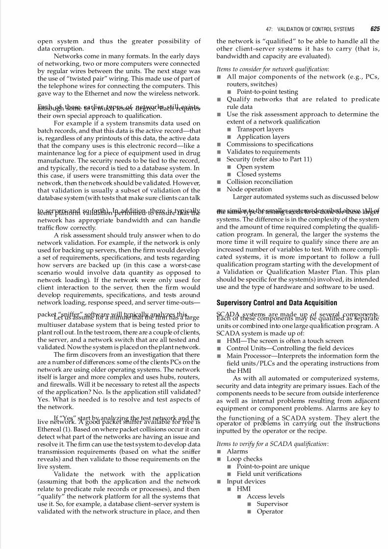
5/17/2018 13243184 Validation Part 8 - slidepdf.com
http://slidepdf.com/reader/full/13243184-validation-part-8 25/143
open system and thus the greater possibility of data corruption.
Networks come in many formats. In the early daysof networking, two or more computers were connected by regular wires between the units. The next stage wasthe use of “twisted pair” wiring. This made use of part of the telephone wires for connecting the computers. Thisgave way to the Ethernet and now the wireless network.
Each of these earlier types of networks still exists,although some to a much lesser degree. Each requirestheir own special approach to qualification.
For example if a system transmits data used on batch records, and that this data is the active record—thatis, regardless of any printouts of this data, the active datathat the company uses is this electronic record—like amaintenance log for a piece of equipment used in drugmanufacture. The security needs to be tied to the record,and typically, the record is tied to a database system. Inthis case, if users were transmitting this data over thenetwork, then the network should be validated. However,that validation is usually a subset of validation of thedatabase system (with tests that make sure clients can talk
to servers and so forth). In addition, there is typicallysome platform validation performed to ensure that thenetwork has appropriate bandwidth and can handletraffic flow correctly.
A risk assessment should truly answer when to donetwork validation. For example, if the network is onlyused for backing up servers, then the firm would developa set of requirements, specifications, and tests regardinghow servers are backed up (in this case a worst-casescenario would involve data quantity as opposed tonetwork loading). If the network were only used forclient interaction to the server, then the firm woulddevelop requirements, specifications, and tests aroundnetwork loading, response speed, and server time-outs—
packet “sniffer” software will typically analyzes this.Let us assume for a minute that the firm has a largemultiuser database system that is being tested prior toplant roll out. In the test room, there are a couple of clients,the server, and a network switch that are all tested andvalidated. Nowthe system is placed on the plant network.
The firm discovers from an investigation that thereare a number of differences: some of the clients PCs on thenetwork are using older operating systems. The networkitself is larger and more complex and uses hubs, routers,and firewalls. Will it be necessary to retest all the aspectsof the application? No. Is the application still validated?Yes. What is needed is to resolve and test aspects of the network.
If “Yes” start by analyzing the test network and thelive network. A good packet sniffer available for free isEthereal (1). Based on where packet collisions occur it candetect what part of the networks are having an issue andresolve it. The firm can use the test system to develop datatransmission requirements (based on what the snifferreveals) and then validate to those requirements on thelive system.
Validate the network with the application(assuming that both the application and the networkrelate to predicate rule records or processes), and then“qualify” the network platform for all the systems thatuse it. So, for example, a database client–server system isvalidated with the network structure in place, and then
the network is “qualified” to be able to handle all theother client–server systems it has to carry (that is, bandwidth and capacity are evaluated).
Items to consider for network qualification:& All major components of the network (e.g., PCs,
routers, switches)& Point-to-point testing
& Qualify networks that are related to predicaterule data
& Use the risk assessment approach to determine theextent of a network qualification& Transport layers& Application layers
& Commissions to specifications& Validates to requirements& Security (refer also to Part 11)
& Open system& Closed systems
& Collision reconciliation& Node operation
Larger automated systems such as discussed below
are similar to the smaller systems described above. All of the same type of testing needs to be done for these largersystems. The difference is in the complexity of the systemand the amount of time required completing the qualifi-cation program. In general, the larger the systems themore time it will require to qualify since there are anincreased number of variables to test. With more compli-cated systems, it is more important to follow a fullqualification program starting with the development of a Validation or Qualification Master Plan. This planshould be specific for the system(s) involved, its intendeduse and the type of hardware and software to be used.
Supervisory Control and Data Acquisition
SCADA systems are made up of several components.Each of these components may be qualified as separateunits or combined into one large qualification program. ASCADA system is made up of:& HMI—The screen is often a touch screen& Control Units—Controlling the field devices& Main Processor—Interprets the information form the
field units/PLCs and the operating instructions fromthe HMI
As with all automated or computerized systems,security and data integrity are primary issues. Each of thecomponents needs to be secure from outside interferenceas well as internal problems resulting from adjacentequipment or component problems. Alarms are key to
the functioning of a SCADA system. They alert theoperator of problems in carrying out the instructionsinputted by the operator or the recipe.
Items to verify for a SCADA qualification:& Alarms& Loop checks
& Point-to-point are unique& Field unit verifications
& Input devices& HMI
& Access levels& Supervisor& Operator
47: VALIDATION OF CONTROL SYSTEMS 625
5/17/2018 13243184 Validation Part 8 - slidepdf.com
http://slidepdf.com/reader/full/13243184-validation-part-8 26/143
& Disks& Tapes
& Graphics& Is the system represented correctly on the screen?
& Data acquisition and data integrity& Is the screen a true representation of the system?& Is it a touch screen?& Interface between the screen and the system (i.e.,
valves, temp. control, etc.).& Does the screen do what is indicated in the
system?& Calibration
Distributed Control SystemsDCSs have evolved over the years into sophisticatedunits. These systems are usually involved in more than just pharmaceutical manufacturing. They are found ininventory control, warehousing, ordering, maintenance,and manufacturing controls. BMS and MRP Systems areexamples of DCS systems. These systems integrate manyfunctions into one package. The BMS controls andmonitors the environmental conditions in the facility. It
can prepare documentation on the environmental statusof any part of the plant if requested or as part of a batchrecord. It can monitor the fire alarms or access torestricted areas.
MRPs on the other hand, are made up of sub-modules that monitor or control inventory, financialrecords, warehousing operations, production schedules,etc. While not all sub-modules are GMP systems, all must be considered in order to assure that no part interfereswith any other part during their operation.
As BMSs are configurable off-the-shelf packages,risk assessment should focus on testing on the configuredand customized portions of the package and not on thestandard components of the package. For example, the
package allows the firm to graphically trend points.Testing should therefore ensure that the set of points to be trended is correctly configured, but the operation of zoom, forward, and back buttons on the standard trendscreen can be ignored.
Items to verify for a DCS:& Individual node/unit can function independently
& No interference between units& No interference between users
& Each node/unit can be qualified independently& Environmental conditions for each node& Input and Out devices& Network qualification&
HMI qualification
PART 11
No discussion of computer or control system qualificationwill becompletewithout at least an overviewof Part 11 (21CFR Part 11). This part of the CFR has caused thepharmaceutical industry great concern in recent yearsdue to its perceived complexity. Part 11 has been aroundsince 1997 but has only recently become more strictlyenforced by the FDA. The reason for this is, the FDAallowed the industry time to comply, by updating theircontrol systems, updating their operating procedures,training, etc., before strict enforcement would be
implemented. According to the latest guidelines,systems put into operation prior to 1997 are usuallyconsidered exempt from the Part 11 rules. However,caution needs to be taken here, as any change to thesystem after the 1997 start, may bring the control systemunder Part 11 requirements.
When one looks closely at the requirements, theyare really quite understandable; however, their
implementation can be very complex. The FDA hasissued two sets of guidelines for this Part of the CFR.The first set of guidelines has been withdrawn and a new“draft” guideline has been issued. The current guidelines,has made compliance to Part 11 regulations clearer to theindustry. The regulations have not changed; only theirperception has changed.
There are three major sections of the requirements.These are:& Subpart A—General provisions
& 11.1 Scope& 11.2 Implementation& 11.3 Definitions
& Subpart B—Electronic records&
11.10 Controls for closed systems& 11.30 Controls for open systems& 11.50 Signature manifestations& 11.70 Signature/record linking
& Subpart C—Electronic signatures& 11.100 General requirements& 11.200 Electronic signatures components and
controls& 11.300 Controls for identification codes/
passwordsSubparts B and C represent the main body of the
requirements. Only an overview of the requirements will be presented; further study will be required to fullyunderstand this section of the CFR.
Subpart B is concerned with any computerizedsystem (of any size or type) or of the people who usethese systems. Both open and closed systems are included(11 CFR 11.10 and 11 CFR 11.30). In this part of the CFRthe FDA specifies that any system used to “create, modify,maintain, or transmit electronic records shall employprocedures and controls designed to ensure the authen-ticity, integrity. and ensure that the signer cannotreadily repudiate the signed record as not genuine.”This means that the system(s) need to be validated/qua-lified and that, as with written records, there needs to betraceability of all data. Access to the systems and the dataor records (electronic) needs to be limited and authorized.
Records that are maintained in paper format, as the
final, official copy are not included in this section of theregulations. The paper records are part of what is knownas the predicate rules requirements. The predicate rulesare any rule previously established as found in 21 CFRPart 211.
Subpart C deals with the actual control and require-ments for electronic signatures. It describes the levels forsecurity and access, the need for verification of the personsigning. There are two types of identification discussed;these are biometric and non-biometric. The non-biometricform is most familiar to everyone. These include itemssuch as identification badges (picture ID) sign-in logs,and password. If this type of identification is used, thentwo forms must accompany the signature (i.e., user
626 VIII: COMPUTERIZED SYSTEMS

5/17/2018 13243184 Validation Part 8 - slidepdf.com
http://slidepdf.com/reader/full/13243184-validation-part-8 27/143
identification and a password). On the other hand, a biometric identification would include fingerprint iden-tity, retinal scans of the eye, or voice recognition.Biometric identification is becoming easier and lessexpensive, and is available on some PCs now.
As can be seen from this short discussion of Part 11,the regulations are not difficult; however, some aspects of the rules may be harder to implement. All control systems
have, or should have, limited access to both the systemand the various levels of data (e.g., operator, supervisor,and administrator). Any change in the data needs to havea “trail” indicating “who” made the change and why thechange was made (similar to changes in paper records).Thus, compliance to Part 11 has become achievable and,with the new Guidelines from the FDA, it has becomemore understandable. However, care needs to be takenwith all computerized systems to be sure that all of thePart 11 regulations are implemented.
ACKNOWLEDGMENT
The author acknowledges the assistance and input from
John Hannon on several of the topics in this chapter.
BIBLIOGRAPHY
Code of Federal Regulations 21 CFR Part 11, 2006.Code of Federal Regulations 21 CFR Part 211, 2006.Code of Federal Regulations 21 CFR Part 211 (21 CFR Part 11),
2006.FDA Computerized Devices/Process Guidance, May 1992.FDA General Principles of Software Validation; Final Guidance
for Industry and FDA Staff, January 11, 2002.FDA Guidance for Industry—PAT:A Framework for Innovative
Pharmaceutical Manufacturing and Quality Assurance(draft guideline), August 2003.
FDA Guide to Inspection of Computerized Systems in DrugProcessing, February 1983.
General Principles of Software Validation; Final Guidance forIndustry and FDA Staff, U.S. Department Of Health andHuman Services, Food and Drug Administration Center forDevices and Radiological Health Center for BiologicsEvaluation and Research—January 11, 2002.
Good Automated Manufacturing Practice (GAMP) Guide forValidation of Automated Systems, ISPE, 2001, GAMP 4.
Good Practice and Compliance for Electronic Records andSignatures—Parts 1 and 2, ISPE and PDA, 2002.Guidance for Industry Part 11, Electronic Records; Electronic
Signatures—Scope and Application. U.S. Department of Health and Human Services Food and Drug Adminis-tration Center for Drug Evaluation and Research (CDER)Center for Biologics Evaluation and Research(CBER) Center for Devices and Radiological Health(CDRH) Center for Food Safety and Applied Nutrition(CFSAN) Center for Veterinary Medicine (CVM) Office of Regulatory Affairs (ORA), August 2003.
Guidance for Industry PAT—A Framework for InnovativePharmaceutical Development, Manufacturing, andQuality Assurance—U.S. Department of Health andHuman Services Food and Drug Administration Centerfor Drug Evaluation and Research (CDER) Center forVeterinary Medicine (CVM) Office of Regulatory Affairs(ORA) Pharmaceutical CGMPs, September 2004.
ISPE C & Q.IVT article on PLCs.King JH. A Practical Approach to PLC Validation, Institute of
Validation Technology. Special ed. Computer Validation II,2005.
Technical Report No. 18, Validation of Computer-RelatedSystems, PDA, V49, number S1, 1995.
http://www.ethereal.com/http://www.pacontrol.com/PLC.htmlhttp://www.pacontrol.com/SCADA.htmlhttp://www.pacontrol.com/DCSystem.html
47: VALIDATION OF CONTROL SYSTEMS 627

5/17/2018 13243184 Validation Part 8 - slidepdf.com
http://slidepdf.com/reader/full/13243184-validation-part-8 28/143

5/17/2018 13243184 Validation Part 8 - slidepdf.com
http://slidepdf.com/reader/full/13243184-validation-part-8 29/143
48
Risk-Based Validation of a Laboratory InformationManagement System
R. D. McDowallMcDowall Consulting, Bromley, Kent, U.K.
INTRODUCTION
Pharmaceutical QC laboratories must work electronicallyif they are to survive.
This statement is not made because of regulatoryrequirements but simply business pressures facing thepharmaceutical industry today: profit margins are underpressure from government pricing; also, delays inaccepting or rejecting raw materials, active ingredients
or finished products costs time and money. As analyticallaboratories are at the end of the production chain anydelay is visible and can magnify the cost of other delayselsewhere in production. Therefore, any implementationof a LIMS in a QC laboratory has to provide tangible business bene fits through the elimination of paperrecords and the use of electronic signatures with associ-ated electronic workflows.
Validation of computerized systems has also beenundergoing considerable change following the FDA’sGMPs for the 21st century (1) and its revision of 21 CFR11 with its Guidance for Industry on Part 11 Scope andApplication (2). This has been followed by the GAMPForum’s publication on risk-based electronic records and
signatures (3), which takes a record-based approachrather than a system-based approach to computer vali-dation. There is also a GAMP Forum Good Practice Guideon Validation of Laboratory Computerized Systems (4);only the system implementation life cycle is taken fromthis publication as there are a number of issues asoutlined by the author of this chapter (5). The LIMSvalidation must be cost effective and risk based tohelp deliver the benefits from a process-driven
implementation within a relatively short period of timeor there is little benefit to an organization.
To appreciate and understand the rationale for thisnew approach to implementing a LIMS, it is important tounderstand the problems that face current installations.These can be summarized as follows:& Poor LIMS Implementation: It is difficult to perform an
effective LIMS implementation in many laboratories.Typically the current process is automated resulting ina very expensive typewriter being implemented thatis driven by paper instead of streamlining the processahead of implementing a system.
& No Interfacing to Analytical Instruments: Failure tointerface analytical instrument computer systemsthat generate the bulk of the data in QC laboratoriesto a LIMS resulting in manual entry of data. Manualdata entry is a slow task and requires transcriptionerror checking to ensure accuracy and integrity. It isstill surprising to find the number of LIMS implemen-tations that are standalone and fail to considerinterfacing instruments within the laboratory orapplications outside of it.
& Calculations are Performed Outside of LIMS and Instru-ment Data Systems: Calculations are typicallyperformed in spreadsheets or hand-held calculatorsor calculations which are outside of either the LIMS orthe data system that generated the data. The reasonsfor this are mainly that the data system is unable toprovide the calculation, spreadsheets are widelyavailable and early to use or the laboratory staff cannot be bothered to read the data system manualto implement the calculations.
& No Interfacing to Production Systems: Information andspecifications contained in production systems are nottransferred electronically to the LIMS; these data haveto be input manually into the system and manuallychecked to ensure accuracy.
& Extensive Customization of a Commercial System: Insteadof using the standard workflows within a system,many laboratories implement LIMS by changing thesystem functions to fit the laboratory’s current ways of working. This is inefficientand is based on theassump-tion that a laboratory’s processes are efficient andeffective. This assumption is usually wrong andcreates additional cost and time delays for aLIMS project.
Thus it is unsurprising that many LIMS imple-mentations are inefficient, not cost effective and take along time to validate.
Abbreviations used in this chapter: CD, compact disc; CDS, chroma-tography data system; CFR, Code of Federal Regulations; CIs,configuration items; ELN, Electronic Laboratory Notebook; ERP,Enterprise Resource Planning; FDA, Food and Drug Administration;
FMEA, failure mode and effects analysis; GAMP, good automatedmanufacturing practice; GLP, good laboratory practice; GMP, goodmanufacturing practice; IDEF, integrated definition; IEEE, Instituteof Electrical and Electronic Engineers; IP, internet protocol; IQ,installation qualification; IT, information technology; LC, liquidchromatography; LIMS, Laboratory Information ManagementSystem; NMR, nuclear magnetic resonance; OECD, Organizationof Economic Cooperation and Development; OOS, out-of-specifi-cation; OQ, operational qualification; PQ, performance qualification;QA, quality assurance; QC, quality control; R&D, research anddevelopment; RAID, redundant array of inexpensive disks; RFID,radio frequency identification; RFP, request for proposal; SAN,storage area network; SDS, system design specification; SOP, stan-dard operating procedure; URS, user requirements specification; UV,ultraviolet.

5/17/2018 13243184 Validation Part 8 - slidepdf.com
http://slidepdf.com/reader/full/13243184-validation-part-8 30/143
This chapter on risk-based validation of LIMSdescribes how to deliver substantial and tangible business benefits required of a LIMS in a GMP laboratory by redesigning the process before coupling this with aneffective risk-based computer validation to comply withregulations. This chapter is structured in the followingsections:& Understand and improve the current ways of working&
Designing the LIMS environment& Specify, implement and validate the LIMSThe approach outlined here is based on the use of a
commercial LIMS with configuration or customization of the application as appropriate for a specific laboratory.This section is written primarily for the implementationand risk-based validation of a LIMS in a single laboratoryor site. The modifications of the approach required for amulti-site or global LIMS validation are to define the corerequirements that all laboratories will use within thesystem and the initial validation of the core system thatmust not be modified. Local additions to the core systemmay be permitted but these need to be specified andvalidated locally. A GAMP Good Practice Guide on global
information systems control and compliance may beuseful in this context (6).
UNDERSTAND AND OPTIMIZE THEBUSINESS PROCESS
For successful use of electronic signatures within a new orupgraded LIMS, an electronic workflow is required.Therefore a QC laboratory has to migrate from apaper driven process to an electronic one. This is thekey to a cost beneficial validation of any LIMS: map,analyze, understand and then optimize the businessprocess to work electronically and to use electronicsignatures effectively.
This understanding and redesign work is achievedthrough two process mapping workshops; using theprocess mapping terminology, these are the “As Is”(current) process and the “To Be” (future) process.These two workshops need to be two to four weeksapart as they are relatively intellectually intense; time isneeded for reflection between each workshop so that theresulting material can be reviewed critically. Whenundertaking this work, it is important to realize that theprocess starts and finishes outside of the laboratory andtherefore staff working in areas that interface with thelaboratory need to be involved as well as QC staff.
Understand the Current (As Is) ProcessThe purpose of this workshop is to understand the waythe laboratory currently operates and how computerizedsystems are utilized inside and outside the laboratory.This workshop establishes a baseline and allows theparticipants to critically analyze their ways of working.
The “as is” workshop should cover the followingtopics:& What is process mapping? There are a number of
techniques but either cross-functional processmapping or IDEF are considered by the author to bethe optimal approaches.
& Map the current process used in the laboratories,highlighting differences in working practices.
& Map the boundaries of the current data systems andLIMS (if used).
& Identify spreadsheet and laboratory notebook use.& Identify differences in working practices between
laboratories.& Identify SOPs/test methods used in the process.& Identify process bottlenecks where delays occur and
the reasons for them.& Identify where and why signatures and initials are
used throughout the process.& Obtain process metrics: e.g., how many, how much,
how long, and how often.& Identify process improvement ideas.
It will soon become apparent from this workshopthat processes are inefficient and paper-driven, and thatcomputerized systems are not being used to their fullpotential. An example of an “As Is” process flow for a QClaboratory is shown in Figure 1 which shows that theprocess is paper-driven, as paperwork lists are main-tained outside of the LIMS in addition to informationstored within the data systems and LIMS. Also instru-ments are not connected to the LIMS and calculations are
performed with calculators and spreadsheets. The LIMShas all data manually entered into the system. Whenfaced with a typical “As Is” process map it is obviousthat to implement and validate a LIMS in a QC environ-ment will be a huge waste of resources with little if anypayback for the organization. If a global LIMS is requiredin an organization, process mapping is invaluable, as ithighlights where the differences are between laboratoriesand identifies these as areas for harmonization in thenew process.
Optimize the Process for Electronic WorkingTo improve and optimize the process, a second workshop
is carried out after the draft report from workshop 1 wascirculated for review. Note the careful phraseology: weare optimizing the process not re-engineering it, thereason being that much can be achieved with a shortoptimization workshop rather than a full-scale processreengineering project. The underlying assumption is thatthe basic operation of a regulated QC laboratory is sound;it is only the details that need to be improved orredesigned, not re-engineered.
The three basic operating principles of the elec-tronic laboratory according to Jenkins (7) are as follows:1. Capture Data at the Point of Origin: If you are going to
work electronically, then data must be electronic fromfirst principles. However, there is a wide range of data
types that include observational data (e.g., odor, color,size), instrument data (e.g., pH, LC, UV, NMR, etc.)and computer data (e.g., manipulation or calculationof previous data). The principle of interfacing must be balanced with the business reality of cost-effectiveinterfacing: what are the data volumes and numbersof samples coupled with the frequency of the instru-ment use?
2. Eliminate Transcription Error Checks: The principles fordesign are as follows: never re-enter data and designsimple electronic workflows to transfer data andinformation seamlessly between systems. Thisrequires automatic checks to ensure that data aretransferred and manipulated correctly. Where
630 VIII: COMPUTERIZED SYSTEMS

5/17/2018 13243184 Validation Part 8 - slidepdf.com
http://slidepdf.com/reader/full/13243184-validation-part-8 31/143
appropriate implement security and audit trails fordata integrity and only have networked systems foreffective data and information sharing.
3. Know Where the Data Will Go: Design data locations before implementing any part of the LIMS and theLIMS environment. The fundamental informationrequired is what volumes of data are generated bytheinstrumentation and wherethe data will be stored:
in an archive system, with theindividual data systemsor on a networked drive? The corollary is that securityof the data and backup are of paramount importancein this electronic environment. In addition, file-naming conventions are essential to ensure that alldata are uniquely numbered either manually or auto-matically. If required, any archive and restoreprocesses must be designed and tested to that theyare reliable and robust.
These principles should be used to optimize the “asis” process maps to define the new or “to be” process inthe second workshop, which typically will cover thefollowing items:&
Review the “as is” process maps with modificationwhere necessary to reflect the current working practices.& Optimize and harmonize (especially between labora-
tories) the process and generate the “to be” processusing the following inputs: Improvement ideas gener-ated in workshop 1. Eliminating unnecessary processsteps. Identifying any manual steps to be automated bythe new LIMS or other computer systems.
& Define the new boundaries of the LIMS and othercomputer systems inside and outside the laboratory.
& Identify data transfers between these systems.& Estimate potential time and calculation of time savings
from the new process.& Identify any “quick wins” for rapid implementation
(these are defined as improvement ideas that are cheapto implement but provide high benefit and givecredibility to the overall approach).
The new process map is shown in Figure 2; theprocess has been made electronic and data are transferredto the LIMS electronically from the data systems toeliminate manual data entry. Electronic signatures have been implemented within the LIMS to eliminate much of
the current paper records. Note that paper will not beeliminated entirely but the majority of primary recordswill be electronic. The work list is no longer required asthe information will be maintained electronically.Although the main tasks in the process still remain, thetime taken when working electronically between steps 5,6 and 7 has been cut by approximately 50% to 60% as thesystems are set up to work electronically.
Estimated Benefits of Working ElectronicallyWhen the new process has been defined and mapped, thenew timings of the process can be estimated andcompared with the current process. Based on the
differences between the two, an estimate in overall timeand resource saving can be calculated. Savings should belarge enough to cost-justify the system on tangible business benefits alone including faster product release,quicker acceptance and rejection of raw materials andholding less stock. While intangible benefits such asquality are important, the organization needs to know if there will be a payback from the investment.
However, do not assume that better processes willresult in headcount reduction in a laboratory; what itmeans is that the overall laboratory process will workmore efficiently and faster but the LIMS will meanchanges in the laboratory staff roles. LIMS applicationadministration will be needed where none existed before,
1. Developand Validate
Method
4. AnalyseSample
2. TransferMethod
3. ManageSamples
5. Calculate &InterpretResults
6. Check &Verify
Results7. Release
Product
8. WriteReport / CoA
11. ArchiveResults /
Data
9. Investigate
Out-of-Spec
Results
10. UpdatePre-Defined
Worklist
Figure 1 “As is” process map in a quality control laboratory.
48: RISK-BASED VALIDATION OF A LABORATORY INFORMATION MANAGEMENT SYSTEM 631

5/17/2018 13243184 Validation Part 8 - slidepdf.com
http://slidepdf.com/reader/full/13243184-validation-part-8 32/143
e.g., power users within the laboratory will be the firstline of help for users and staff will be needed for theinputting specifications (if not done automatically) andmethods into the LIMS. Do not underestimate the amountof work that this will entail.
DESIGNING THE LIMS ENVIRONMENT
As stated in the introduction, QC laboratories must workelectronically if they are to survive; therefore, the LIMSenvironment needs to be defined based on the optimizedprocess. The first stage in designing this is to look at aLIMS as an interface between the laboratory and pro-duction. This will be followed by interfacing the LIMSand other computerized systems within the QC labora-tory to produce an electronic LIMS environment tosupport the newly designed process.
Positioning a LIMS: Hitting Two TargetsIt is important to realize that a LIMS should automate both the laboratory where it is implemented andthe production facilities that the laboratory serves. To beeffective a system should deliver benefit to both thelaboratory and the production. How should this beachieved? A LIMS is unlike any other piece of laboratoryautomation equipment available to the analyticalchemist. It can provide benefits both within the labora-tory and outside of it. Thus a LIMS has two targets (8):& The laboratory: the information generator& The organization: the information user
The problem is how to site and implement a systemso that it hits both targets effectively. Figure 3 shows anoutline of the functions that a LIMS should undertake in asimplistic way. The diagram shows a LIMS sited at the
interface between a laboratory and an organization.Samples are generated in the organization and receivedin the LIMS, and then the samples are analyzed within thelaboratory. The data produced during analysis arereduced within the LIMS environment to informationwhich is transmitted back into the organization.Figure 3 represents the ideal positioning of a LIMS: boththe organization and the laboratory benefit, as the linedividing the organization and the laboratory show, andthe system is of equal benefit to both.
The LIMS EnvironmentA successful LIMS implementation builds a LIMSenvironment to serve both the organization and thelaboratory. The key to success is that the LIMS mustintegrate the processes and the computerized systemsin these two areas where analytical information is gener-ated and used.
Some of the applications outside of a laboratory thata LIMS could be interfaced to design the LIMS environ-ment are listed below and in the top half of Figure 4:
& E-mail systems for transmission of reports to custo-mers or keeping them aware of progress withtheir analysis
& Web servers for laboratory customers to viewapproved results and also for contract laboratoriesto input data into the QC LIMS
& ERP systems f or linking the la bora torywith production
& Applications maintaining product specifications& Data warehouses& Electronic Document Management Systems& Failure Investigation Systems& Electronic Submission Systems (for GMP laboratories
in pharmaceutical R&D)
1. Developand Validate
Method
4. AnalyseSample
2. TransferMethod
3. ManageSamples
5. Calculate &
Interpret
Results6. Check &
VerifyResults
7. ReleaseProduct
8. WriteReport / CoA
10. Archive /
ResultsData
9. InvestigateOut-of-Spec
Results
Figure 2 Optimized “to be” electronic process for a laboratory.
632 VIII: COMPUTERIZED SYSTEMS

5/17/2018 13243184 Validation Part 8 - slidepdf.com
http://slidepdf.com/reader/full/13243184-validation-part-8 33/143
These are just a few of the possible applications thata LIMS could be interfaced to; the list of potentialcandidates will be based on the nature of the analyticallaboratory and the production organization it serves.
Some ERP vendors can claim LIMS functionalityand that there is no need to implement a LIMS; however,the problem with this approach is that the ERP’s conceptof a QC laboratory often does not match the reality. For
example, the sample process flows within an ERP tend to be high level and very simplistic and cannot automate alllaboratory functions, e.g., OOS investigations withoutextensive writing of custom software. Once the organiz-ational side of the LIMS environment has been designed,the LIMS environment within the laboratory needs to be designed.
Designing the LIMS environment means that you
need to consider the other systems in the lab that mustinterface with the LIMS. This includes other laboratoryapplications such as scientific data management systems,CDS, and electronic lab notebooks, as well as various datasystems that may be attached to those or run indepen-dently. It also includes analytical instruments,chromatographs, and laboratory observations as shownin the lower half of Figure 4. Data can be transferred to theLIMS by a variety of means:& Direct data capture by the LIMS& Capture by an instrument data system with analysis
and interpretation and only a result is transferred tothe LIMS
& As above but the results or electronic records aretransferred to the LIMS via a Scientific DataManagement System
& Laboratory observations can be written into a note- book then entered manually into the LIMS orcaptured electronically via an ELN and transferredelectronically to LIMS
& Bar codes (or RFID) can be used to label samples andenter data rapidly into the LIMS
Laboratory InformationManagement System (LIMS)
Samples Information
Analysis Data
OrganizationLaboratoryLaboratory
Figure 3 A laboratory information management system deli-
vering benefit to the quality control laboratory and organization.
Organization
Laboratory
Laboratory Information Management System
FailureInvestigation
System
E-Mail SystemEnterpriseResource
Planning
ElectronicDocument
Management
Scientific Data
Management System
Chromatography
Data System
ElectronicLaboratory
Notebook
Analytical Instruments ChromatographsLaboratory
Observations
DataSystem
DataSystem
Figure 4 Options for a laboratoryinformation management systemenvironment to integrate thelaboratory with the organization.
48: RISK-BASED VALIDATION OF A LABORATORY INFORMATION MANAGEMENT SYSTEM 633

5/17/2018 13243184 Validation Part 8 - slidepdf.com
http://slidepdf.com/reader/full/13243184-validation-part-8 34/143
Before implementing a LIMS, it may be appropriatein some laboratories to standardize and implementinstrument data systems, e.g., chromatography datasystem. The rationale for this approach is that a datasystem can be quicker to implement than a LIMS and itwill provide a firm foundation to build the LIMS above it.If it is done the other way around, the data system mayneed to be updated later with a consequent change in
working practices and more revalidation.
LIMS IMPLEMENTATION AND RISK-BASEDVALIDATION
This section of the chapter deals with the systemimplementation life cycle as outlined by the GAMPGood Practice Guide for Laboratory ComputerizedSystems (4) and modified by McDowall (5). The aim isto realize and deliver through the LIMS those business benefits identified in the process redesign in a cost-effective manner.
Electronic Records Generated by a LIMS ina GMP EnvironmentThe change from a system to a record-based approach tothe validation of computerized systems was initiated bythe FDA in the Guidance for Industry on Part 11 Scopeand Application (2). The GAMP Good Practice Guide forCompliant Part 11 Records and Signatures (3) has takenthis and developed a risk-based approach to validation of a computerized system based on the impact of the recordsgenerated and managed by an application.
The records generated and managed by a LIMS in aGMP environment are high impact as they are either usedin product release and/or product submission. Someexamples of electronic records that could be contained
within a system are listed below, this list should not beconsidered exhaustive as it depends on how a specificLIMS has been implemented and used:& Specifications of products, intermediates and
raw materials& Stability protocol& Sampling methods& Analytical methods& Worklists& Observations and results captured directly by the
LIMS, e.g., pH and balance measurements& Results transferred from analytical systems& Comparison of results versus specification and
identification of OOS results
& OOS investigations and where appropriate addi-tional results& Electronic signatures& Certificates of analysis& Audit trail entries& Instrument qualification and calibration status
The electronic records need to be identified anddocumented (2). It is important to understand that this isnot a static process; as the LIMS is updated the newversion may contain new functions that may create newelectronic records in addition to those listed above. If newfunctions are added using the scripting language, thenthese may also create new electronic records. Therefore, itis important to review this list on a regular basis; when
the system is upgraded and during a periodic review arethe obvious times.
These are high impact records as defined by GAMP(3) as they can impact product quality and/or patientsafety. Therefore, a more rigorous approach should beadopted which includes:& Hazard Identification: The hazards that the LIMS could
faceshouldbe identified along with theconsequencesof
each one. However, although a hazard and its associ-ated consequences mayhave been identified, we do notknow if a specific one poses a risk to the system. Toidentify the potential risks to the system, a risk assess-ment needs to be undertaken.
& Risk Assessment: For each hazard identified, the severityof the consequence and probability of occurrence bothneed to be estimated; this is achieved by allocatingeither high, medium or low (3). There are differentclasses of hazard such as human, software, hardware,IT support, physical and environmental. Risks will beclassifiedaseitherasclass1,2or3(high,mediumorlowrisks) to identify which risks are important enough toimplement mitigation controls.
& Control Selection: Controls for electronic records andelectronic signatures generated by systems can beimplemented at a number of levels: Organization viapolicies and standards, e.g., validation policy and pass-words. Procedural (and implicitly training) via SOPs,e.g., user manual and change control. Application andnetwork via technical controls such as audit trail,application and/or network security and checks. ITInfrastructure via network security, backup andrecovery, hardware and network redundancy.Computer system validation.
Owing tothenature ofa LIMSin a QCLaboratory inaGMP environment, the system will require validation plusother controls to mitigate risk and protect the electronic
records such as application security and access control andone or more audit trails for working electronically. Inaddition, the server needs to have redundant componentssuch as dual processors, disk controllers and RAID disks toensure that data are protected and not lost dueto hardwarefailure. This section will concentrate on the risk-basedvalidation of a LIMS; it is intended to build upon theprocess redesign and design of the LIMS environmentoutlined earlier to ensure a successful and cost-effectiveLIMS implementation.
System Implementation Life Cycle ActivitiesFor the purposes of simplicity, the implementation life
cycle will begin with either the implementation of a newsystem or an upgrade of an existing LIMS. This means thewriting of the initial URS used to generate the RFP used inthe system selection process, the system selection andaudit of the vendor will be omitted from this chapter. Forreaders that want to understand this part of the life cycleprocess should read the appropriate chapters fromMcDowall (9). Therefore, the start of the implementationlife cycle here will be where either:& A new LIMS to be configured and installed in a
laboratory but with an outline URS used to selectthe specific system
& An existing LIMS installation which will be upgradedto the latest application version.
634 VIII: COMPUTERIZED SYSTEMS

5/17/2018 13243184 Validation Part 8 - slidepdf.com
http://slidepdf.com/reader/full/13243184-validation-part-8 35/143
There are three main work streams to consider thatare outlined below and presented in Figure 5:& Specification, installation, and qualification of the
computer hardware& Validation of the LIMS application& Writing procedures and training the users
Tasks for the three streams are shown and this willhelp to put the remaining tasks in this section
into context.
Updating the User Requirements SpecificationFor a new system, there will be an initial LIMS URSavailable for system selection; however, it will needupdating for the purchased new version of the appli-cation. The reason for this is that the URS used for systemselection is general in character and is unlikely to besufficiently specific to design tests for the validation of the selected LIMS. Therefore, an application and versionspecific URS needs to be written that defines the intendeduse of the system and contains the functions and thecapabilities required by the system. It is this documentthat the PQ tests will be based on using the risk assess-
ment and traceability matrix documents.For the LIMS upgrade, the existing version of the
URS will not cover all the new functions available, andthis document needs to be reviewed and updated whereappropriate. This should be the easier job as users will betrained on the current version of the system. The releasenotes provided by the application vendor will be useful tohighlight areas where the URS will need to be updated if the laboratory intends to use them (see below). Eachrequirement in the URS should be prioritized as eithermandatory (must have requirement) or desirable (nice tohave but if not available the LIMS functionality is notimpaired) (9).
Read the Application Release Notes To focus on the changes that have occurred in a newrelease of the LIMS software, read the software releasenotes to understand the nature of the new features thathave been added as well as the software errors that have been fixed. Although this sounds simple and straightfor-ward, in reality this is more complex due to the way thatthe pharmaceutical industry handles software in aregulated environment. If version 2 of a LIMS applicationhas been installed and validated, typically the laboratorywill miss the next release, version 3, unless there is a goodreason for change. Version 4 of the LIMS will beimplemented instead; thus, the laboratory implements
every other version of the software rather than keepingcurrent due to the perceived cost and effort of validation.Therefore, reading the release notes of the last two (ormore) versions of the software and understanding theimpact is the norm rather than the exception. This meansthat new features need to be understood and prototypedto understand their value and potential impact on thelaboratory’s ways of working.
Using Process Maps to Define System Requirements An additional advantage of the “To Be” process maps istheir use in facilitating the requirements for the LIMS andthe other systems used in the LIMS environment. Thetraditional problem with writing requirements for any
computerized system is that obtaining requirements can be akin to extracting teeth from the users. The termi-nology “gathering requirements” implies that they arefreely available to be written down but often nothing isfurther from the truth. The advantage of the process mapsis that they provide an effective medium for obtainingrequirements. Each activity in the process map has inputsand outputs defined from the workshops. A facilitator
then needs to ask the laboratory users what happens ineach process activity. This means that the requirementscan be more precisely defined providing a greatercertainty in system specification, selection and validationas the users are focused on a specific task.
Better Definition of User Requirements: The Role of Prototyping Prototyping is an important tool to help understand howa new LIMS application or the new features of an upgradecan work within a laboratory. The corollary is that usersmust have been trained on the new version of the soft-ware rather than reading the on-line help files. Featurescan be evaluated in an unqualified installation to identify
if they are useful and then to refine how each one may beused to best advantage and business benefit. Although itis valuable, prototyping has to be handled with care; onlytwo rounds of prototyping should be undertaken, e.g.,high level to determine which functions should be in theimplementation and which should be excluded followed by a second round for further in depth evaluation of theselected options and finalizing the details of operation.
There is a danger that prototyping can be unstruc-tured with little documentation from the exercise. Fromexperience, the best way to tackle this is to have asdefined outputs from each phase of the prototyping anupdate of the URS plus outline testing documents. If theLIMS scripting language is being used during this work,then documentation of the functions being modifiedneeds to be generated and maintained.
All of these documents should be uncontrolled butunless they are available for review outside of the projectteam, the second phase of the prototyping work cannotproceed. This approach is intended to instill the disciplineto ensure the work is documented as it goes on but also isan investment in time to reduce the amount of effortneeded later to write the PQ test scripts.
Defining Electronic Signature Use During the prototyping phase, electronic signature useshould be evaluated to support the electronic workflows
that were designed in the process redesign phase. It isimportant to understand the need to differentiate between identification of actions and signing of records.The former is akin to the correction of an error in alaboratory notebook, where an entry is struck throughwithout obliterating the original, corrected and then theinitials and date of the person making the entry areappended. The latter is the formal signing of the pagein the laboratory notebook by the owner to state theyaccept responsibility for the correct data above onthe page.
For many companies, it is unfortunate that compli-ance has overridden the regulations and many recordsare signed by custom and practice than need to be. The 21
48: RISK-BASED VALIDATION OF A LABORATORY INFORMATION MANAGEMENT SYSTEM 635

5/17/2018 13243184 Validation Part 8 - slidepdf.com
http://slidepdf.com/reader/full/13243184-validation-part-8 36/143
Write SystemRequirements
Specification
Risk Assessment& Traceability
MatrixIdentify
Procedures
System DesignSpecification
ValidationTasks
IT PlatformComponents
TrainingUsers
Server IQ and OQ
Install and IQLIMS Software
Install CitrixViewer on
Workstations
Configure LIMSand Functions
Write SOPs
Connect DataSystems &
Instruments
Train UsersWrite and
Approve PQ TestPlan and Scripts
Execute PQ TestScripts
Update andApprove SOPs
Write ValidationSummary Report
Release LIMS for
Operational Use
Figure 5 Outline tasks involved in a laboratory information management system risk-based validation.
636 VIII: COMPUTERIZED SYSTEMS

5/17/2018 13243184 Validation Part 8 - slidepdf.com
http://slidepdf.com/reader/full/13243184-validation-part-8 37/143
CFR 211 regulations simply state that only two signers areneeded per test (§194(a) sub-clauses 7 and 8) (10), the firstto state that the results generated are correct and a secondperson signed to say they have been checked for accuracyand the correct procedures have been followed. There-fore, the LIMS needs to reflect the regulation rather thanelectronically sign everything.
Write the Validation PlanFor a new system implementation, a validation plan isrequired to control the work of the validation. As aminimum it should define the roles and responsibilitiesof all individuals working on the project, the life cycle to be followed and the documentation to be written at eachstage of the project. In addition, for global or site projects,the overall validation strategy should be presented: howthe development and validation of a core application forall sites will be achieved along with the documentation tosupport it, then how it will be installed at each site andunder which conditions an instance can be modified by alocal site.
For an upgrade of an existing LIMS, a changecontrol request could suffice to control the work butinevitably a validation plan is written as the work willusually involve replacement of the server and modifi-cations of the current ways of working.
Combined Risk Assessment and Traceability MatrixRisk assessment is now a key validation requirementfollowing the FDA’s Part 11 Scope and Applicationguidance (2). After the URS was written, both thesystem and the individual functions were assessed forregulatory and business risk using the Functional RiskAssessment methodology (9,11). Here individual systemfunctions are assessed as either critical or not critical (C or
N respectively) from a regulatory and/or business riskperspective. Coupled with the prioritization in the userURS, each requirement is graded as either mandatory ordesirable as well as either critical or noncritical; these can be plotted in a 2!2 Boston grid to determine overall risk.Only functions that were both mandatory and criticalwere considered for PQ testing; all other combinations arenot considered any further. The rationale for this is basedon the vendor’s testing of the application.
Mandatory and critical functions were then evalu-ated further to see if they need to be:& Explicitly tested and then assigned a specific test
script number where similar functions aretested together
& Assumed to work as there was no access to eitherthe algorithm
& Implicitly tested such as the windows and somedisplay functions
& Verified during the qualification of the system& Traced to a procedure or an SOP
This is a simpler process for a commercial systemthan the modified FMEA outlined in Appendix M4 of theGAMP guide (12).
System ArchitectureThe vendor’s recommendations should be used by theorganization’s IT Department to size and specify the
database and application servers for the system. If terminal servers (e.g., Citrix Metaframe) are to be used,these need to be specified, as will the other LIMSinstances used for evaluation, training, validation andproduction. Diagrams of the overall system architecturewill help to understand the approach taken and should beencouraged to be drawn for inclusion here. Increasinglyrather than have a server for each instance, virtual servers
are used running within an environment such asVMware; this is useful to reduce hardware costs andmaintain individual instances of the LIMS. Data caneither be attached to the production server in a RAIDconfiguration or increasingly SAN devices are used. Alldetails concerning the system architecture should bedocumented in a SDS or equivalent as this is an inputinto the configuration records for the overall system.
System IQ and OQServer IQ Plans and Installation Installation plans for all the servers (database and appli-cation instances as well as any Citrix servers used for theapplication) should be written by the IT Department.These plans should include the installation of the hard-ware and documenting its con-figuration as well asinstalling and configuring the operating system and anyutilities for each server, e.g., agents for backup, networkmanagement software, etc. The installation of hardware,operating system and any utilities for all servers mustfollow these plans and record the actual details of eachserver installed such as serial number and configuration(memory, processor type and speed and IP address, etc.).
LIMS Database, LIMS Application and Instrument Interface IQ The activities that are involved in this task should be:
& An evaluation of the vendor’s installation qualifica-tion documentation to check that it is acceptable.
& Installing the LIMS database and software on therespective servers for each instance by either amember of organization’s IT staff or the vendor’sservice personnel. At the same time the applicationIQ is completed and followed by a review of thedocuments to ensure that the instructions tests have been performed with acceptable results.
& The analytical equipment and instruments to beinterfaced to the LIMS in the initial phase of theLIMS implementation will be interfaced now andchecked that the connections work. Again, this will be planned and there will be documentation availableto demonstrate the activities undertaken.
Establish Change Control and Configuration Management Now Once the servers and application has been installed, thesystem needs to be placed under change control. Someorganizations write a specific change control SOP for eachsystem; however, the smarter ones will have a singleprocedure that is applicable to all regulated systems.Allied with change control is configuration managementwhich is just as important but often neglected. Configu-ration management is the definition of the CIs thatconstitute the whole system. CIs consist of:
48: RISK-BASED VALIDATION OF A LABORATORY INFORMATION MANAGEMENT SYSTEM 637

5/17/2018 13243184 Validation Part 8 - slidepdf.com
http://slidepdf.com/reader/full/13243184-validation-part-8 38/143
& Hardware& Software& Documentation (ranging from vendor supplied
material including electronic manuals to company-specific documents)
The level of detail required should be sufficient toprovide business benefit from the information, e.g.,server information will require make, model, processorsize and speed, memory, disk size and configuration,operating system and service pack, and network infor-mation such as IP address, etc. Less information would be required of a workstation, e.g., typically this would bethe minimum specification available to run the appli-cation within the company as many organizationschange workstations every three to four years. When achange is made, the configuration management records before and after the change should document what CIshave been modified, added or removed.
Do I Need a LIMS Application OQ? Traditionally there is now an operational qualificationto demonstrate that the LIMS application software
works as the vendor intended it to. Here is wherewe can take advantage of a risk-based approach tocomputer validation. Most OQ packages offered byLIMS vendors are their internal test suites, usedeither “As Is” process or modified for external salefor demonstrating that the unconfigured applicationworks. Look at the process: the vendor produces andtests the base application, manufactures the CD fromwhich you install the same software. Do you need toexecute essentially the same tests that the vendor has?No. Furthermore, the application that is installed will be configured by the laboratory to their own ways of working away from the base package, making theexecution of a comprehensive OQ a further waste of
time. Therefore this stage should be omitted from anyLIMS validation as it adds little if any value to theoverall work and is relatively expensive and timeconsuming to perform. If the PQ works then theapplication functions.
Configuring the SystemLIMS do not have “ON” buttons and therefore eachinstallation will need to be configured to the laboratoriesworking practices as noted earlier in this section underuser requirements. Depending on the vendor and appli-cation chosen this can be achieved in a variety of wayseither alone or in combination:&
Configuration by selecting one of a series of optionsoffered by the vendor. For example, selecting theaccess privileges for a specific user type
& Configuration within the boundaries of the LIMSapplication by using the scripting language supplied by the vendor
& Customization by writing new functionality to extendthe LIMS
This section will look at how this work needs to beundertaken, tested and documented.
Do I Need a Functional Specification? Notnecessarily, as it depends on howany additional LIMSfunctionality is implemented and how extensive the work
will be. What is important is that the configuration of theLIMS is recorded rather than what a document is called.The URS can contain the majority of requirements of thesystem but the detail needs to be recorded in one or moreconfiguration documents. However, if the LIMS will beextensively configured then an overall functional specifi-cation is advised and this will have traceability back tothe URS. Note that a single URS requirement may
generate more than one requirement within thefunctional specification.
Using the LIMS Scripting Language Before starting any work with the scripting, languagedevelopers will need to be trained and understand theimplications of use. Alternatively, this is an area whichthe vendor and their staff could be engaged to develop onthe behalf of the laboratory. If prototyping has been usedearlier to generate requirements and workflows theresulting scripts can be used again here. If the vendorpublishes any standards for using the language theseshould be followed as good practice. Where possible,the scripts should be reviewed by a second person before being implemented. Copies of the scripts used tomodify the LIMS functions should be maintained outsideof the system in case of disaster; do not rely solely onrecovery from magnetic backup tape to preserve them.
The output from the configuration should be testedagainst requirements or other specifications to ensure thatthey are correct. Correctly performing configurations arecopied into the validation environment prior to the PQ.
Input of Methods and Specifications Populating the database with methods and the corre-sponding specifications will take time and should not beoverlooked when planning the project. Although this
process will start during the configuration, the processwill be ongoing throughout the operational life time of theLIMS as new products and specifications are added to thesystem. The ideal for specifications is to download theinformation from another system where it is maintainedelectronically; however, often specifications are main-tained on paper and this requires the laboratory to inputand check them manually before transferring them to theoperational instance. Similarly, methods will need to beinputted to theLIMS and controlled; inevitably this will bea manual process, although once entered methods can becopied from one product and adapted to another one.
Write SOPs and Train UsersUsers and IT operations staff will need to write or modifythe SOPs identified in the URS for the various operationsof the LIMS. This typically ranges from basic useroperations, through application and system support, todatabase maintenance. Either these SOPs need to beavailable in final draft form when the PQ is executed toenable any changes required to be incorporated before thedocuments were approved and released or they areapproved before the PQ and if any changes are requiredafter the PQ these will be identified as they are checkedout during the PQ. All users of the system, including theIT support staff need to be trained as appropriate to theirtasks and records maintained of these activities.
638 VIII: COMPUTERIZED SYSTEMS

5/17/2018 13243184 Validation Part 8 - slidepdf.com
http://slidepdf.com/reader/full/13243184-validation-part-8 39/143
Initially only the staff involved with the PQ willneed to be trained on the SOPs; however, before otherusers are allowed to use the operational system they willneed to be trained. Care must be taken over training asLIMS may have long learning curves and it is neither fairnor reasonable to expect laboratory personnel to work atthe same level immediately after LIMS training as theywill still be getting to grips with a new application. This is
less of an issue with an upgrade; however, it dependshow many versions have been skipped.
LIMS Performance Qualification orEnd-User TestingThe purpose of the end-user testing or PQ is to demon-strate that the functions specified in the URS work asintended to meet both business and regulatory require-ments for the LIMS. Terminology here can be confusingwithin the analytical laboratory as IQ, OQ and PQ areused for both analytical equipment qualification andcomputerized system validation but mean differentthings (9). Also the terminology used to describe the
documents generated in this phase of validation workcan differ greatly; it is important to remember that thework is done and documented rather than what aparticular document is called.
Test Plan for Controlling the PQ A test plan based on IEEE standard 829 is used to controlthe work (13). This is achieved by defining the system to be tested and its scope. It can list the test scripts to bewritten and link these back to the URS requirements to betested under each test script and the features not to betested (13). Testing cannot be exhaustive, so there is also asection on the assumptions, exclusions, and limitations to
the testing; this is a very useful way of recordingcontemporaneous notes of why testing was conductingin a particular way.
PQ Test Scripts The test scripts or protocols are written in sufficientdetail to test the requirements in the URS; traceability back to the requirements is important from two perspec-tives. The first is to check coverage of testing versusrequirements and the second is to check that the require-ments are testable or verifiable. Occasionally the URSmay need to be updated at this stage to modify somerequirements that cannot be tested or verified
adequately or it is realized that a requirement has beenwritten incorrectly.Testing of the system should cover its main func-
tions including instruments and systems that have beeninterfaced with the LIMS plus the overall capacity of thesystem. If the LIMS is interfaced with an ERP system,then many of the test scripts will start in the ERP bygenerating a work order that is downloaded to the LIMS;at the end the analytical release will be sent to the ERP.It is important to realize that although the basicoperations of the LIMS must be validated before oper-ational release, many of the database population activitieswill be controlled by procedure and do not requirevalidation per se.
Approved PQ test scripts are executed and docu-mented evidence in both paper and electronic form arecollected; test results should be compared with explicitlystated acceptance criteria. It is important to use screenshots sparingly, where the system does not record infor-mation within the database or audit trail and where theyadd value. Similarly, witness testing is not an FDArequirement but validation custom and practice;
however a second person review is mandatory. Theresults of this were documented in the respective testscripts and summarized in the validation summaryreport for the LIMS; a specific PQ report need not be written.
Write System Description and Definition ofE-RecordsA system description should be written and approvedfor the LIMS. The best format for this document is foundin the outline requirements contained in the Applicationof GLP Principles to Computerized Systems from theOECD (14). In addition, the system description should
also contain the definition of electronic records for thesystem and the fact that 21 CFR 11 applied to theapplication as required by the Part 11 Scope and Appli-cation guidance (2).
Reporting the ValidationBefore writing any validation summary report, the firstactivity is to read the applicable validation plan andunderstand what the original intent of the validationwas. This will identify if deviations have occurred thathave not been explained previously.
Write Validation Summary Report and Release the Core System This validation report contained the summary of thevalidation of the core system and was issued after thevalidation of the core system (the first rollout). A state-ment in the validation summary report released thesystem for operational use including electronic signa-tures. The report was reviewed and approved by thesystem owners and QA prior to releasing the system foroperational use.
Write Validation Summary Report for Each Rollout of the System Each additional phase of the system rollout had a vali-dation summary report written to describe the work thathas been undertaken in that phase to maintain theoriginal validation status of the system. These tasksincluded a summary of the evidence for:& Any additional servers installed and qualified& Interfacing of any new instruments or systems to
the LIMS& Updated configuration logs& Any further or repeat PQ test scripts executed under
the PQ test plan& User training performed and an updated list of
authorized users for the system
48: RISK-BASED VALIDATION OF A LABORATORY INFORMATION MANAGEMENT SYSTEM 639
5/17/2018 13243184 Validation Part 8 - slidepdf.com
http://slidepdf.com/reader/full/13243184-validation-part-8 40/143
SUMMARY
Risk-based validation of a LIMS opens up theopportunity for organizations to streamline the amountof work that they undertaken and focus the effort on theareas of highest business and regulatory risk.
REFERENCES
1. FDA. Good Manufacturing Practices for the 21st Century,2002.
2. FDA. Guidance for Industry: Part 11 Scope and Appli-cation, 2003.
3. Good Automated Manufacturing Practice (GAMP), GoodPractice Guide on Compliance Part 11 Electronic Recordsand Electronic Signatures, International Society forPharmaceutical Engineering, Tampa, FL, 2005.
4. Good Automated Manufacturing Practice (GAMP), GoodPractice Guide on Laboratory Computerised Systems,International Society for Pharmaceutical Engineering,Tampa, FL, 2005.
5. McDowall RD. Validation of spectrometry software:critique of the GAMP good practice guide for validationof laboratory computerized systems. Spectroscopy 2006;21(4):15–30.
6. Good Automated Manufacturing Practice (GAMP), GoodPractice Guide on Global Information Systems Complianceand Control, International Society for PharmaceuticalEngineering, Tampa, FL, 2005.
7. Jenkins S. Pittsburgh. Conference 2004 Presentation on thePaperless Laboratory.
8. McDowall RD. Chemometrics and intelligent laboratorysystems. Lab Automation Info Manag 1995; 31:57–64.
9. McDowall RD. Validation of Chromatography Data
Systems: Meeting Business and Regulatory Requirements.Cambridge: Royal Society of Chemistry, 2005.10. Good Manufacturing Practice Regulations 21 CFR 211.11. McDowall RD. Effective and practical risk management
options for computerised system validation. Qual Assur J2005; 9:196–227.
12. Good Automated Manufacturing Practice (GAMP), Guide-lines version 4, International Society for PharmaceuticalEngineering, Tampa, FL, 2001.
13. Software Engineering Standard 829 on Software Test Docu-mentation, Institute of Electrical and Electronic Engineers,Piscataway, NJ, 1998.
14. Application of GLP Principles to Computerised Systems,Organisation for Economic Co-operation and Develop-ment, Paris, 1995.
640 VIII: COMPUTERIZED SYSTEMS

5/17/2018 13243184 Validation Part 8 - slidepdf.com
http://slidepdf.com/reader/full/13243184-validation-part-8 41/143
49
Validation of Laboratory Information Systems
Alex M. ZislinDSCI, Freehold, New Jersey, U.S.A.
Rory BudihandojoBoehringer-Ingelheim Chemicals, Petersburg, Virginia, U.S.A.
Jeffrey M. Singer PharmaBasics, Inc., Douglaston, New York, U.S.A.
INTRODUCTION
Today’s pharmaceutical manufacturing environment hasgenerated a large body of requirements for data frommanufacturing processes, in-line testing, off-line testing,product testing, intermediary, stability, potency, raw
material qualification, etc. In addition, there is also datathat comes from clinical trials, i.e., API blood serum levels,metabolite levels, etc. The common thread with these datais that they are generated by laboratory testing on unequi-vocally identified samples using validated methods onqualified instruments, analyzed by validated algorithmson qualified computers, stored on validated computersystems, and reported by validated reporting functionson these and other validated computer systems thataccess the stored data. In addition, some or all of thesedata may be submitted to regulatory agencies as part of the submissions required to license a new API, or toexpand the indications of an existing API. In all of theabove examples, the system that generates, analyzes,stores and reports on this data must be in a ValidatedState, if it handles GxP-related data.
SCOPE
The techniques, practices and approaches described inthis chapter reflect the current regulatory thinking interms of validation, risk, and PAT (1–7). In addition tothe standard validation methodologies and practices, this
chapter will address some of the implications of therecently released risk-based GMP guidance. The goal of any system validation effort is to determine the fitness forintended use, where use is defined by the full andqualified set of end-user requirements. The successfulcompletion of the validation activities themselvesgenerate the objective documented evidence that thesystem is installed, operates, and performs as specified.These objectives are the same for all automated systems.
In addition to starting off with a validated system, itis important (and required) to maintain the system in avalidated state during its entire useful life. Activities thatprovide this are also described in this chapter.
SYSTEM DEFINITION
For the purposes of this chapter, it is considered thatLIMSs are computer-based systems, consisting of inte-grated hardware (instruments, computers, etc.) andsoftware (applications, instrument software, etc.) thatperform one or more of the following functions eitheralone or in conjunction with other associated systems:& Data storage and data management& Data acquisition from multiple instruments& Data acquisition from manual entry& Sample management& Laboratory scheduling&
Data source—MSDS& Data source—laboratory procedures& Data source—laboratory material specifications& Interface with automated instruments& Interface with Laboratory Automation Systems& Instrument control& Laboratory workflow control& Environmental monitoring& Data analysis& OOS notification& NCE notification& Laboratory user training& Reporting—results, OOS, NCE& Data archive
Abbreviations used in this chapter: API, active pharmaceutical ingre-dient; APR, annual product review; CFR, Code of FederalRegulations; COTS, configurable off-the-shelf; DS, design specifi-cation; FDA, Food and Drug Administration; FRS, functionalrequirement specification; FS, function specification; GAMP, goodautomated manufacturing practice; GMP, good manufacturing prac-tice; GUI, graphical user interface; GXP, good practices(manufacturing, practice, and laboratory practice); HPLC, high-performance liquid chromatography; IEEE, Institute of Electricaland Electronic Engineers; IQ, installation qualification; IQP, installa-tion qualification plan/protocol; ISO, International Organization for
Standardization; ISPE, International Society for PharmaceuticalEngineering; LAN, local area network; LIMS, Laboratory Infor-mation Management System; MFG, manufacturing; MSDS,material safety data sheet; NCE, non-conforming event; OOS, out-of-specification; OQ, operational qualification; OQP, operationalqualification plan; OS, operating system; PAT, process analyticaltechnology; PQ, performance qualification; PQP, performance quali-fication plan/protocol; QA, quality assurance; R&D, research anddevelopment; RTM, requirements traceability matrix; SDLC, soft-ware development life cycle; SEI, Software Engineering Institute;SILC, system implementation life cycle; SIPOC, suppliers, inputs,process, outputs, consumers; SOP, standard operating procedure;SPC, statistical process control; UAT, user acceptance testing; UFRS,user functional requirements specification; URS, user requirementsspecification.

5/17/2018 13243184 Validation Part 8 - slidepdf.com
http://slidepdf.com/reader/full/13243184-validation-part-8 42/143
& Data backup and restore& Laboratory resource planning (analysts, instruments,
chemical standards, etc.)& Trending (e.g., for SPC)& APR reporting
Figure 1 illustrates a representative architecture fora LIMS implementation. Note that the connections to theLIMS can take several forms ranging from a standalone
instrument to instruments controlled by clients eitherdirectly connected to the LAN or connected through agateway for remotely sited systems.
The actual LIMS itself may be developed in-house,purchased as a turnkey COTS system, or a combination of COTS and in-house development/configuration. In anyinstance, the validation should consider the full SDLC toensure that the system is fully validated. There are somepractitioners who prefer to follow the GAMP SILC modelfor LIMS validation. (8). The overall end result is similar,the key difference being that the SDLC covers the actualfunctional design and coding of the LIMS, whereas theSILC emphasizes design qualification. Figure 2 illustratesthe differences and convergences of SDLC and SILC
process flows.This chapter will cover the case of a configurable
COTS system and refers to additional activities thatwould be required for a custom LIMS development.
For purposes of system planning, implementationand validation, it is important to define fully the scopeand boundaries of the LIMS in such a manner as to reveala comprehensive and compliant requirements set. In thisway, all of the aforementioned activities can be botheffective and efficient.
PROJECT PLANNING
Different guidelines suggest that Project Planning beginsat different points in the total acquisition/implementa-tion/validation process. The actual time of initiating aProject Plan is somewhat fluid depending upon theinternal practices at a particular site. Some suggest thatplanning begins after user requirements are written,while some suggest that planning begins upon thedecision to procure and implement a new or upgradedsystem (9–19). It is more desirable to have a plan fromwhich to work as soon as possible even though theplan will require updates and details at each phase of the project. For purposes of this chapter, a Project Planwill be considered one of the first deliverables in thevalidation process. Once the decision is made to goforward with a LIMS, a comprehensive Validation Plancan be used to describe how proceeding will greatlyenhance the ability to define the project, predict theresources (budgetary and personnel) required, identifyany critical path challenges and estimate the expectedcompletion date.
A typical Project Plan at this stage would be verysimple and includes the following items:& General System Description& Scope of the System& Expected Budget& Make or Buy Criteria and/or Decision& Resources Required (internal and external)& Initial Estimate of Schedule
& Major Tasks and Decision Point Milestones only& Criteria and Deliverables required for next decision
point
Protocols
LAN
LIMS Clientw/
Instrument
LIMS ApplicationServer
LIMS Client
Instrument – LANConnected
Controlled Remotely
Stand Alone Instrument –No Direct LIMS Interface
Methods
Data
Networked Instrument – LANConnected via Gateway
Controlled Remotely
Figure 1 Representative LIMS imple-mentation.
642 VIII: COMPUTERIZED SYSTEMS

5/17/2018 13243184 Validation Part 8 - slidepdf.com
http://slidepdf.com/reader/full/13243184-validation-part-8 43/143
& URS&
System Validation Plan or Validation Plan& Risk Assessment and Risk Management Plan
Defining the SystemOne of the most difficult activities in any computer-related activity is defining the system. How does onewrite a comprehensive set of requirements withoutunderstanding what tasks and functions the systemmust do, may already perform, or may need to replace?There are a number of techniques for obtaining require-ments, but all have three common attributes: subjectmatter expertise, user bias, and documentation. We
shall illustrate a potential requirement derivation tech-
nique based on Six Sigma methodologies (20).As an initial step, define the system SIPOC diagram(Fig. 3). This approach allows simultaneous considerationof the customer/end-user needs, system inputs/outputs,and matches requirements to each of these while identi-fying critical process steps.
While the SIPOC gives a high-level overview of thesystem, the next step of process mapping allows therequirements definition to proceed by identifying work-flow, functions, subprocess, etc. An important output of this mapping level is the identification of potential riskitems, process inefficiencies, and process gaps; all of which can be mitigated through the use of alreadyidentified requirements or addition of new requirements.
Need Assessment
Vendor Assessment
Functional Specification
User Requirements Specification
Unit and Integration Testing
Code Review
Code Development
Design Qualification
Design Specification
Design Qualification
Installation Qualification (IQ)
Operational Qualification (OQ)
Performance Qualification (PQ)
System Release
System Use / System Maintenance
Change Control / Configuration Management
Periodic Review
System Retirement
SDLC
SILC
Figure 2 System design life cycle(SDLC) and SILC process flows.Source : From Ref. 8.
49: VALIDATION OF LABORATORY INFORMATION SYSTEMS 643

5/17/2018 13243184 Validation Part 8 - slidepdf.com
http://slidepdf.com/reader/full/13243184-validation-part-8 44/143
System Complexity and RiskThe GAMP Good Practice Guide: Validation of Labora-tory Computerized Systems describes the categorizationof various LIMSs based on their complexity and use. Forcompleteness, Table 1 displays the GAMP 4 categories
(21) and Table 2 depicts the LIMS categories (8).
Requirements DefinitionReferring to Table 3, the first activity and validationdeliverable described is the URS. The URS is a formaldescription of the system’s performance as viewed fromthe user’s frame of reference. Depending on thecomplexity of the system, the requirements should statewhat the system shall do and what capabilities it willhave, not how it does it or how the capabilities are to beimplemented. For example:& The LIMS shall provide security measures for
ensuring that data is not modified or deleted once it
is entered into the system.& The system shall provide the capability to preventunauthorized users from accessing the functions,configuration, or data contained within the system.
& The LIMS shall provide the users the capability tosignify review and approval through the use of electronic signatures that comply with 21 CFR Part 11.
& The system shall provide the user the ability to viewHPLC chromatograms while the run sequence isin progress.
& The system shall provide the capability to generatehard copy reports of trend analysis and the under-lying raw data.
& The system shall provide the user control of specifiedinstrument functions (i.e., initiate, calibrate, run,
pause, end).Note that in the above requirements, it is stated that. the system shall provide the capability.. These simpleexamples illustrate the traits of a well-defined require-ment. Each requirement defines one item that the systemshall do (related to what the user wants), the item ismeasurable, testable, and/or verifiable by independentmeans (validation), and it allows the system developer orvendor to provide the most efficient way of fulfilling therequirement (implementation). The URS also providespotential vendors a common description of the systemto propose their LIMS solution against end-user evalu-ation in the case of a purchased system.
For more complex systems or development
systems, an additional document (FS) specifies the func-tions required to meet each user requirement. Forexample, consider the electronic signature requirementin the URS. Some possible functional requirements would be as follows:& Electronic signatures shall require the use of one or
more biomet ric identifie rs unique to e achauthorized user.
& LIMS instrument data shall be stored in humanreadable formats.
Suppliers RequirementsCustomersOutputsProcessInputs
Process Step 1
Process Step ..NProcess Step 3
Process Step 2
ClinicalInvestigator
SitesMFG
QA
SampleSample IDReagentsSoftware
ConstantsUser ID
CalibrationStatus
Sample IDResults
NotificationsData for
Submission
ClinicalRegulatory
MFGQA
R&D
Reqmt 1Reqmt 2
.
.
.
Figure 3 Suppliers, inputs, process,outputs, consumers diagram.
Table 1 Good Automated Manufacturing Practice Software Categories
Category Software type Validation approach
1 OS Record version (e.g., WinXP Service Pack 2). OS indirectly challenged byapplication functional testing
2 Firmware Non-configurablerecord version, calibrate instruments as required, verify
operation against user requirements
Configurablerecord version and configuration, calibrate instruments as
required, verify operation against user requirements
Custommanage firmware as Category 5 software
3 Standard software packages Record version and environment configuration, verify operation against user
requirements
For critical and complex application, consider a supplier audit as well
4 Configurable software packages Record version and configuration, verify operation against user requirements
Supplier audits for critical and complex applications
Manage custom programming as Category 5
5 Custom software Audit supplier and perform complete system validation
Source : From Ref. 14.
644 VIII: COMPUTERIZED SYSTEMS

5/17/2018 13243184 Validation Part 8 - slidepdf.com
http://slidepdf.com/reader/full/13243184-validation-part-8 45/143
T a b l e 2
G o o d A u t o m a t e d M a n u f a c t u r
i n g P r a c t i c e L a b o r a t o r y S y s t e m
C a t e g o r i z a t i o n
C h a r a c t e r i s t i c s
o r r u l e s f o r
c a t e g o r i e s
I n c r e a s i n g
c o m p l e x i t y /
A
B
C
D
E
F
G
C o n fi g u r a t i o n
S o f t w a r e a n d
c o n fi g u r a t i o n i s
n o t m o d i fi a b l e
S o f t w a r e a n d
c o n fi g u r a t i o n i s
n o t m o d i fi a b l e
C o n fi g u r a t i o n
p a r a m e
t e r s s t o r e d
a n d r e u
s e d
C o n fi g u r a t i o n
p a r a m e t e r s s t o r e d
a n d r e u s e d
C o n fi g u r a t i o n
p
a r a m e t e r s s t o r e d
a
n d r e u s e d
C o n fi g u r a t i o n
p a r a m e t e r s s t o r e d
a n d r e u s e d
C u s t o m
s y s t e m s
P r o p r i e t a r y
c o n fi g u r a b l e
e l e m e n t s ,
i . e . , n o t
c h a n g i n g c o r e c o d e
C o m p l e x l o g i c
f u n c t i o n s , m a c r o s
I n t e r f a c e s
N o c o m p u t e r
i n t e r f a c e u s e d
N o c o m p u t e r
i n t e r f a c e u s e d
N o c o m p u
t e r i n t e r f a c e
u s e d
M a y h a v e 1 : 1 r a t i o
( c o m p u t e r t o
i n s t r u m e n t i n t e r f a c e ,
s e r v e r t o c l i e n t
i n t e r f a c e )
M a y h a v e 1 : 1 r a t i o
( c o m p u t e r t o
i n s t r u m e n t i n t e r f a c e ,
s
e r v e r t o c l i e n t
i n t e r f a c e )
M a y h a v e 1 : M ( m a n y )
r a t i o ( c o m p u t e r t o
i n s t r u m e n t i n t e r f a c e
,
s e r v e r t o c l i e n t
i n t e r f a c e )
C u s t o m
s y s t e m
D a t a p r o c e s s i n g
C o n v e r s i o n o f A / D
s i g n a l s
C o n v e r s i o n o f A / D
s i g n a l s
D a t a m a n i p u l a t e d b y a
s e p a r a t e p r o g r a m
e x t e r n a l t o t h e
s y s t e m
P o s t - a c q u i s i t i o n
p
r o c e s s i n g d o n e a s
p
a r t o f t h e s y s t e m
( c a n a n a l y z e d a t a
w
i t h p r o p r i e t a r y d a t a
h
a n d l i n g s y s t e m )
P o s t - a c q u i s i t i o n
p r o c e s s i n g d o n e a s
p a r t o f t h e s y s t e m
( c a n a n a l y z e d a t a
w i t h p r o p r i e t a r y d a t a
h a n d l i n g s y s t e m )
C u s t o m
s y s t e m
R e s u l t s a n d d a t a
s t o r a g e
I n f o r m a t i o n g e n e r a t e d
b a s e d u p o n
i n s t r u m e n t f u n c t i o n i s
s t o r e d ,
i . e . ,
c a l i b r a t i o n d a t a i s
s t o r e d
P r o c e s s p
a r a m e t e r s
i n p u t a n
d s t o r e d
( r u n t i m e
p a r a m e t e r s ,
m e t h o d s
p a r a m e
t e r s )
P r o c e s s p a r a m e t e r s
i n p u t a n d s t o r e d
( r u n t i m e p a r a m e t e r s ,
m e t h o d s
p a r a m e t e r s )
P r o
c e s s p a r a m e t e r s
i n p u t a n d s t o r e d
( r u n t i m e p a r a m e t e r s ,
m
e t h o d s
p
a r a m e t e r s )
P r o c e s s p a r a m e t e r s
i n p u t a n d s t o r e d
( r u n t i m e p a r a m e t e r s ,
m e t h o d s
p a r a m e t e r s )
C u s t o m
s y s t e m
D o e s N O T p r o d u
c e r a w
d a t a o r t e s t r e s u l t s
P r o d u c e s r a w
d a t a o r
t e s t r e s u l t s ,
b u t
r e c o r d s n o t s t o r e d o r
p r o c e s s e d
P r o d u c e s
r a w
d a t a o r
t e s t r e s u l t s ,
b u t
r e c o r d s
n o t s t o r e d o r
p r o c e s s
e d
P r o d u c e s r a w
d a t a o r
t e s t r e s u l t s ,
b u t
r e c o r d s a r e s t o r e d
b u t n o t p r o c e s s e d
P r o
d u c e s r a w
d a t a o r
t e s t r e s u l t s ,
b u t
r e c o r d s a r e s t o r e d
a
n d p r o c e s s e d
P r o d u c e s r a w
d a t a o r
t e s t r e s u l t s ,
b u t
r e c o r d s a r e s t o r e d
a n d p r o c e s s e d
C u s t o m
s y s t e m
49: VALIDATION OF LABORATORY INFORMATION SYSTEMS 645
5/17/2018 13243184 Validation Part 8 - slidepdf.com
http://slidepdf.com/reader/full/13243184-validation-part-8 46/143
& LIMS control shall be accessed through a commonGUI.
The first functional requirement indicates that elec-tronic signatures are to be implemented and controlledvia biometric means. The actual means of control (e.g.,fingerprint, handwriting characteristics, retinal scan, etc.)are defined in the DSs generated for a full developmentmodel. The second functional requirement indicates thatdata storage is to be implemented so that a user candirectly read the data, and the third indicates that a
common GUI shall be used for all control functions.Again, the actual implementation is defined in the DS.For COTS systems, the vendor generates these documentsas part of their development cycle.
The ordering and grouping of requirements withinthe URS is up to the user group responsible for generatingthis area of documentation. One could list the require-ments as they are identified, and then group them ashardware, software, internal interfaces, external inter-faces, security, etc.
Another approach for developing the URS is toidentify the departments and the users within eachdepartment that will be using the LIMS. Each department
may then identify current practices or current processflow, along with the SOPs that are currently being used.The requirements can then be developed based on thecurrent process flow and how the “future process flow”should be (desired goal). In the future process flow,functions can be identified as performed manually, auto-mated by LIMS, or a combination of automationand manual.
Additionally, for each of the process flows, a riskanalysis can be done to determine if the process has asignificant risk factor in terms of data accuracy,integrity, and authenticity. Mitigation to those riskfactors can then be incorporated as part of theLIMS requirements.
Risk ManagementIn the most recent 21 CFR Part 11 guidance document(22), the FDA has indicated that the extent of computersystem validation should be based on the impact thesystem can have on the ability to meet the requirementsof the applicable predicate rules. In addition, the docu-ment further states that consideration must be given tothe potential risks to accuracy, integrity, etc. of theelectronic records. In a similar vein, ISPE has noted thatthe user must identify and define the GxP records basedon predicate rules, risk to product safety, efficacy, quality,and process criticality. In addition, the capability of someLIMSs to actually control the analytical processes down tothe instrument procedure level requires the user to assessthe potential risk with respect to the accurate generationof original data in electronic form.
Risk is managed by the implementation of controlsthat prevent and/or mitigate and/or document/alarm theoccurrence of a risk condition. For each risk item ident-ified, there may be one or more controls, and forcompleteness, each control is derived from a requirementthat is necessary to control the identified risk item.Additional requirements may be needed to ensure that
all identified risks are controlled.Since the system validation will be against all therequirements, the risk controls will be validated as well. Itis important to note that Risk Management is a processthat continues through the entire system life cycle. Forexample, any change (i.e., update, version upgrade, newinstrument or function) to the system has the possibilityof introducing a new risk, or negating the mitigation of anexisting risk, thereby causing the addition of new require-ments (Fig. 4).
Validation PlanningOne of the earliest deliverables in any software validationproject is the Validation Plan, and this is typically
Table 3 Validation Deliverables
System implementation life cycle Software development life cycle
A B C D E F G
Validation plan Validation plan Validation plan Validation plan Validation plan
Requirements
specification
Requirements
specification
Requirements
specification
Requirements
specification
Requirements
specification
URS URS
Functional
specification
Functional
specification
Risk Risk Risk Risk Risk Risk RiskSupplier
assessment
Supplier
assessment
Supplier
assessment
Supplier
assessment
Supplier
assessment
Detailed design
spec
Detailed design
spec
Code develop
Code review
Unit/integration
test
Unit/integration
test
Design
qualification/IQ
Design quali-
fication/IQ
Design quali-
fication/IQ
Design quali-
fication
Design quali-
fication
Design quali-
fication
Design quali-
fication
IQ IQ IQ IQ
Calibration
qualification/PQ
Calibration
qualification/PQ
OQ/PQ OQ/PQ OQ OQ OQ
PQ PQ PQ
Traceability Traceability Traceability Traceability Traceability Traceability TraceabilityValidation report Validation report Validation report Validation report Validation report Validation report Validation report
646 VIII: COMPUTERIZED SYSTEMS

5/17/2018 13243184 Validation Part 8 - slidepdf.com
http://slidepdf.com/reader/full/13243184-validation-part-8 47/143
reflected in the Project Plan described above (which isoften written prior to or concurrently with the userrequirements). In this manner, expectations, methods,and controls for the validation activities can be defined.For example, in Table 3 it is noted in GAMP 4 thatValidation Plans may not be required for systems thatfall into categories A and/or B. It has been the authors’experience that a site-wide guidance document is invalu-able to serve as a checklist or benchmark for thequalification of these simpler systems. This preventsoverlooking an item that may be unimportant for onedevice, yet critical for another (e.g., temperature control iscritical to ovens and incubators, but temperature moni-toring may be a key requirement for pH or index of refraction measurements.) In addition, documentingand following this type of guidance is an indication tothe regulatory authorities that your processes areunder control.
The general topics covered under Validation Plansinclude the following:& Introduction, Objective and Scope [introduction to the
system, what the goal of the project is (new system,upgrade, incremental expansion.), the level of vali-dation to be performed (i.e., full, partial, regression,etc.) and what the document covers].
&
System Description (key functions, components,inputs, and outputs of the system. What is includedin the system, takes note of interfaces). Describe whatis new, what is an upgrade, what is being remove-d/replaced, key processes affected.
& References (including regulatory, internal documentslike the URS, SOPs, system guides, etc.).
& Validation Strategy—general description of how thevalidation will be approached, and a description of critical areas such as the following:& Additional Scope (i.e., additional items that fall
within or outside the project scope)& Environment (test, production, pilot)& Interfaces
& Test Personnel& Special Test Equipment, Software, and/or
Supplies& Data Migration and/or previous system retire-
ment& Tasks and Deliverables
& Documents at each stage (URS, Risk Assessment,Validation Plan and Protocols, Results andReports, Traceability Matrices, etc.)
& Roles and Responsibilities& Documentation Management& Change Control—statement or acknowledgment of a
procedure and/or policy that facilitates change& Periodic Review to maintain Validated State& Change Control Procedures to Validated System& Acceptance Criteria—what testing outcomes consti-
tute completion and present the system in a ValidatedState.
Function and Design (SDLC)A full representation of the SDLC is beyond the scope of this discussion. The reader is referred to the referencesand to additional material and Software Standards fromthe IEEE, and the SEI material on Software EngineeringPractices, Capability Maturity Models and Software
Development (23–26). It should be sufficient to note thatthe LIMS vendor must be held to the standardsmentioned in order to assure the quality of the initialproduct and its final installation in the end-users’ labora-tories. This can be verified with a vendor assessment, bywhich the vendor submits written responses to customerqueries, preferably in a checklist format. This can befollowed up with an on-site vendor audit, with theparticipation of key members of the validation team, asdescribed below. In the case of a full audit, the actualvendor documentation will be reviewed, including testdata, code reviews, design documents, etc. In addition,for custom development items, the user is often an activeparticipant in design and test result reviews as part of the
InitialConcept
RequirementsAnalysis
DesignDevelop
Configure
Validation
ProductLaunch
Post marketMonitoring
RiskAssessment
RiskAnalysis
Evaluation
RiskReduction/
Control
RiskMitigation
RiskMonitoring
RI S K MA NA GE ME NT
P
R OD U C T L I F E C Y C L E
P r o d u c t I m p r o v e m e n t s
RiskAnalysis
ISO 14971
RiskEvaluationISO 14971
Risk ControlISO 14971
PostProductionInformationISO 14971
Figure 4 Risk management flow
chart (after GAMP 4).
49: VALIDATION OF LABORATORY INFORMATION SYSTEMS 647

5/17/2018 13243184 Validation Part 8 - slidepdf.com
http://slidepdf.com/reader/full/13243184-validation-part-8 48/143
overall system Acceptance Criteria. If the LIMS is aninternal development project, all the phases of theSDLC process should be followed as would be expected by best practices.
Design Qualification (SILC)Limiting the discussion to the SILC model, we considerthe steps required to validate the purchased system. First
is the selection of the vendor system that best meets therequirements developed and documented in the UserRequirements Document. It is very likely that novendor will meet all the requirements that have beendefined, so a method of grading each vendor’s offeringagainst the needs should be defined and the criticalrequirements (i.e., key functions, those that mitigaterisk, or meet regulatory demands) be weighted appro-priately. Again, the criteria should be documented so thatall internal stakeholders are aligned during the selectionprocess. Part of the selection process should include theresults of a vendor compliance audit. For example, doesthe vendor follow accepted industry practice in the areaof software development and testing? Is their documen-
tation sufficient to hold up under regulatory agencyaudit? Does the vendor meet the claim of compliancewith 21 CFR Part 11 and is this proof documented? Is thedesign and function of the software compatible withthe needs of the end-user laboratory? Is the workflow of the laboratories able to be mapped to the softwarefunctions? Does the software interface with the existinglaboratory instrumentation and any near term or futureinstrumentation under consideration? Does the softwarefollow industry standard approaches in interfacedefinitions, database connectivity? Will support for theLIMS be supplied by internal resources, or will a supportcontract be required? Does the level of vendor supplieddocumentation meet the LIMS end-user’s internal docu-
mentation requirements? If this is the desired vendor, andone or more critical issues are not met, then it is the end-user’s responsibility to make up for the deficiencies.These deficiencies would be documented in the riskidentification and the corrective action covered in themitigation activities described previously.
Validation (SDLC and SILC)Installation Qualification The IQ is the activity that provides objective documentedevidence that the LIMS is installed in accordance withvendor, user and engineering specifications. As with any
testing that follows best practices, a protocol is required.This protocol consists of sections that describe the systemto be installed, the environment and required serviceswhere the physical installation will take place, lists thecomponents (software, hardware, interfaces, etc.) and hasscripts that when followed install and document thesystem. Some of the components may already be inplace; for example, the LAN which is usually acompany-wide network, the building utilities includingUPS and environmental controls, and often the instru-ments that are to be connected.
The typical practice is to perform the system IQ in atest environment. In this way, the installation strategy of the system can be verified, any changes required by the
user’s production environment can be identified and theinstallation scripts can be modified under documentChange Control. In addition, the production environmentremains pristine and data collected from the validationactivities does not adversely impact any regulated activi-ties or data in the production environment.
For more complex systems, it may be advantageousto perform the IQ and OQ of the LIMS instrumentation
separately from the LIMS system computer system. Thisdecision should be noted in the System Validation Plandescribed previously.
For larger and more complex systems, there may bemultiple IQ documents and respective activities. Forexample, there may be a separate LIMS Server IQ, aLIMS client IQ that is exercised for each client installed,instrument IQs, software application IQs (operatingsystem, application, database, etc.). In the case of purchased systems, a large portion of these protocolsmay be vendor supplied. In this case, it is the user’sresponsibility to review the material for its content andapplicability to their requirements and anticipated use.The user bears the responsibility for performing an IQ
that is tailored to the business interests of the specificlaboratory environment, according to approved guide-lines and SOPs.
It is important to note here that LIMSs are not static;they grow with additional workload (i.e., new APIs,formulations, etc.) and they change with new technology(i.e., addition of new assays and instrumentation, newfunctionality, retirement of old instruments, etc.). If thesystem is designed with this in mind, and the ValidationPlanning also takes this into account, the amount of validation effort needed to qualify expansion and newtechnology can be limited to the new addition, or change,and does not require a full validation of the entire system.
At the completion of the IQ activities, there will be
documentation that:& Identifies and describes all system components such
as the following:& Hardware& Software& Laboratory Instrumentation linked to the LIMS& Special Purpose Instrumentation (i.e., protocol
converters, A/D data loggers, etc.)& Identifies and describes the system configuration
as installed.In addition, the user, administration, and technical
manuals will also be available. For those instances wherea new assay or instrument is added to an already
qualified system, the documentation will consist of supplemental items that:& Describes the new addition& Describes the IQ steps to add, or remove, or change
the new system& References material that takes into account the
requirements of the establishment’s Change Controlprocedure (see Section entitled Change Control).
Operational Qualification The OQ is designed to provide the objective documentedevidence that the LIMS functions according to the require-ments derivedfromthe functional specifications within theoperating range specified in the user environment.
648 VIII: COMPUTERIZED SYSTEMS

5/17/2018 13243184 Validation Part 8 - slidepdf.com
http://slidepdf.com/reader/full/13243184-validation-part-8 49/143
The functional specifications that are tested in the OQ arisefrom the user-defined Functional Requirements Documentor, forthe caseof purchased systems, from thespecificationssupplied by the vendor.
At the completion of the OQ activities, there will bedocumentation that:& Identifies and describes all system component func-
tions that were activated and tested, for example:
& System security items (user logon, passwordexpiration, administrative rights, etc.)& Laboratory Instrumentation command and
data transfer& Verification of the functioning of Special Purpose
Instrumentation (i.e., protocol converters, A/Ddata loggers, etc.)
& Audit trails (a key requirement for regulatedsystems per 21 CFR Part 11. Audit trails areautomatic software logging of changes to thesystem and the data contained therein. Theyallow for the review of what the system and/ordata was before the change, what the newsystem/or data is, who made the change, when
the change was made, and why. They also log theoriginal creation of the data including source,date, user, etc.)
& Backup/Archive and Restore—all systems thatstore process and business critical data shouldhave regular backups performed, and copies of the data be stored offsite in the event of systemfailures and business interruptions. It is stronglysuggested that this function be verified prior touse in a production environment. Data backupsshould also include the audit trail datanoted above.
& Configuration tables (i.e., user security level
rights, report generation, alarm logging, etc.)& Identifies and describes the system configuration asconfigured. This information is often reviewed duringcompliance audits to verify that the system andinternal processes are under control.
Performance Qualification PQ, also referred to as UAT, is designed to provide testsaddressing the functional requirements from normal business processes as stated in the System RequirementsSpecification and clearly demonstrate performancewithin the actual operating environment of the system.
At the completion of the PQ activities, there will bedocumentation such as the following:& A Validation Summary Report (VSR), which is
developed to document the test results and anydeviations from the OQ, IQ, and PQ/UAT Protocols.
& SOPs that are in place to assure that the applicationremains in a Validated State during production use.
& SOPs that are in place that describe how the system is
to be used, rules for access to functions and data, backup schedules, etc.
& System Release Memo, which when approved isissued to release the system for production use.
Trace Matrix (Requirements/Validation) The RTM is designed to trace the URS, FRS, and DSrequirements and specifications to the specific testsections in the IQ, OQ, and PQ protocols. An exampleof this traceability is illustrated in Table 4. It is importantto note that every requirement is associated with at leastone test protocol. For complex systems, it is useful to keepthe trace matrix in a database or a commercially availablerequirements tracking tool. With this approach, databasequeries can be exercised to find those requirements thatmay not have been tested.
Change ControlOnce the system has been validated, it is considered to beunder Change Control. In essence, this means that anychange to the configuration, configuration items,procedures, methods, instrumentation, etc. must bereviewed by a Change Control Board per user site’sSOPs. Depending on the complexity of the change andtheassociated risk to thesystem, procedures, data, etc., thesystem will most likely have to undergo some level of
revalidation. The more extensive and complex the changethat is contemplated, the more risk is associated, andconsequently the more validation effort will have to beapplied. As previouslydiscussedin the “Validation (SDLCand SILC)” section, for additional equipment changes,decommissioning of instruments, interfaces, and com-ponents, it is best to qualify the instrument separatelyfrom the LIMS and then perform the integration of theinstrument to theLIMSas part of theLIMSChange Controlprocess.The purpose of theintegration process is to ensurethat the instrument link and communication function asexpected. Ideally, there should be a “Development and/or
Table 4 Traceability of Requirements ExampleRequirement/
specificationnumber
Requirement/
specificationdescription
DS number (optional
for system or life cycleimplementation) IQ section/step OQ section/step PQ section/step
User
requirements
specification
# 3.4.1
Requirement
description
8.3.4 6.7.2/step 1
Functional
requirement
specification
# 6.1.6
Requirement
description
11.9 3.5.1
UFRS 4.1.7 Requirement
description
5.2 6.1.2
49: VALIDATION OF LABORATORY INFORMATION SYSTEMS 649

5/17/2018 13243184 Validation Part 8 - slidepdf.com
http://slidepdf.com/reader/full/13243184-validation-part-8 50/143
Test” server that can be utilized to test the changes to theLIMS before going into a “Production” server.
Configuration ControlIn the following paragraphs, we consider “ConfigurationManagement” or “Configuration Control.” ConfigurationManagement relates more to the items that make up theLIMSs (e.g., the software, hardware, manuals, SOPs).
These items can be categorized as “configuration items.”It has been the authors’ experience that this is often
blurred in practice, leading to some endless meetingsabout whether to unplug a printer. It is suggested thatthe following definitions be applied. Configuration iswhat is plugged in, what is considered as consumablesthat does not require Change Control, what versions of software, etc. Change Control is the replacement of acurrent item with a new one (i.e., new instrument, newversion of software, etc.). Like-for-like can be covered asconfiguration management in order to avoid undergoingthe Change Control process every time a light bulbis replaced.
A key consideration of any complex system is the
state of its current configuration. Configuration, for thepurposes of this discussion, is the description thatprecisely describes the system at any point in its lifecycle (refer to GAMP 4). It is a recommended practiceto document the configuration of the system from theinitial state at which it was validated and to maintainthat configuration knowledge (and documentation) forthe entire life of the system. Any change to the system(see the previous section on change control) willinvariably require, at a minimum, verification of thecurrent state of the system and documentation of thechange. More complex or involved changes will alterthe configuration of the system thus altering its stateand the accompanying description (configuration
specification). A good rule of thumb as to whetherthe configuration management practices are acceptableor not is the usability of the documented configurationitems to reconstruct the LIMS from scratch. The con-figuration items should be able to identify all thenecessary components that are required to assemblethe LIMS system just the way it was.
Additional Discussion and Points of ConsiderationValidation Full vs. Incremental Validation In order to determine the level of validation or revalida-tion required, there must be an appropriate description of the policy or practice for partial upgrade. For example,
how does the laboratory validate/commission a newHPLC on the LIMS network? Commission the instru-ment, verify it talks to the LIMS, run a limited PQ?How about a partial software upgrade? Does a fullIQ/OQ/PQ need to be executed, or can this bedetermined and verified in the test environment and avery limited PQ performed in production? In the simplestapproach, refer to the Risk Management Plan that wasdeveloped as part of the LIMS implementation. Acomprehensive plan will have included the level of riskassociated with each of these possibilities. Based on thelevel of risk indicated, the depth of validation can bedefined and the user will be in alignment with currentguidance from the FDA.
Single-Site vs. Multiple-Site Implementation Aside from initial implementation strategy (e.g., big bangimplementation on all sites or multiple-phased imple-mentation, architecture and performance issues such as bandwidth and throughput capability), control andimplementation of changes is a key aspect of themultiple-site implementation.
It is advantageous to consider how the Analytical
Procedure will be maintained and deployed in theinstance of a multi-site LIMS implementation. Forexample, with regard to some site stability studies, thedeployment of new Analytical Procedures and/or upda-tes/changes to existing Analytical Procedures at one sitemay be different from other sites that still utilize the olderversions of Analytical Procedures or instrumentation; or,when a particular site may not be ready to have adeployment of the new Analytical Procedure for somereason. In cases of multinational implementation,languages and character set(s) requirements (and verifi-cation) should also be considered.
Another point of consideration is how the Analyti-cal Procedure will be maintained and deployed in the
case of multiple-site LIMS (e.g., some site or stabilitystudies may still utilize the older versions of AnalyticalProcedure; equipment, and operating conditions may bedifferent from site to site, etc.).
Data Archival Strategy on archiving data and the retrieval of the archivemust be verified to ensure that there is a process forarchiving and retrieving data without overwriting thecurrent data (e.g., the audit trail data, analytical methodprocedures, instrument data, etc.). Strategy for main-taining archived data should also be considered. Forexample, a process should be in place for removingarchived data that is no longer required. Another
consideration is the storage location of the archive or atrue copy, in case of disaster.
Meta Data Meta data is data that describe the data. For example, anHPLC chromatogram would be expected to have trans-mission (absorbance) versus wavelength for each sample.Meta data associated with the chromatographic outputinclude sample ID, instrument used, analyst name,analysis date and time, reviewer name, review nameand time, column information, etc. Meta data are alsorequired by 21 CFR Part 11 as they are considered a partof the original data, and thus must be treated in a manner
similar to the data that they are associated with. Forexample, changes to the meta data must also be capturedin an audit trail.
Disaster Recovery Development of a strategy for Disaster Recovery shouldalso be considered. The plan should cover how to recoverthe hardware, software, and data failures; for example,contact points or persons to recover each of those com-ponents. It is best to practice the Disaster Recovery plan before a disaster strikes. Related to this Disaster Recoveryplan is Business Contingency Planning, on how the business operation can be sustained while the LIMS isnot available, and what to do when the LIMS becomes
650 VIII: COMPUTERIZED SYSTEMS

5/17/2018 13243184 Validation Part 8 - slidepdf.com
http://slidepdf.com/reader/full/13243184-validation-part-8 51/143
available again. For example, how to manually entersample results to LIMS that were obtained when theLIMS was not operational. As part of this DisasterRecovery effort, rollback capability to a certain timepointor restore points should also be considered.
Training Aspects of training should also be considered; for
example, the differentiation of responsibility betweenthe System Administrator, Super User and RegularUser, as well as the other roles that are defined in theLIMS structure. Another aspect of training that shouldalso be considered is the training for the team memberswho will be involved in the development of the LIMS(e.g., programming standard requirements, ChangeControl requirements, documentation requirements,etc.). As a follow up to the rollout, training of manage-ment and their role(s) in the overall process andsustaining effort should also be considered.
External Audits
As GxP computerized systems, LIMSs are subject to 21CFR Part 11 as well as to any applicable predicate rules.Thus, LIMSs are subject to audits by outside authorities(i.e., regulatory) as key items in the manufacturingof pharmaceuticals.
Aspects of External Audits that should beconsidered include providing access to the LIMS in casesuch an access is requested, as well as electronic copyprovision. It is best to have a Super User conduct thenavigation of the LIMS, should access to the LIMS berequested by an external regulator.
CFR 21 Part 11 (Electronic Records and Electronic
Signature Regulations)Last but not least to be considered is the potential impactof CFR 21 Part 11 regulations; for example, importantaspects of system access (e.g., remote access), audit trailmaintenance and access, interfaces compliance (inboundand outbound) with other systems, and user ID mainten-ance to ensure that records can always be traced to theperson who created, edited, and deleted the record (e.g.,how to deactivate user ID without losing the user ID).Open or Closed System classification should also beconsidered, especially if there are interfaces to external(to the company) systems (e.g., Clinical ResearchOrganization).
CONCLUSION
LIMS validation requires considerable effort acrossmultiple departments or levels of authority, corporatecommitment in terms of financial and personnelresources, intelligent planning, and a lot of patience. Attimes it may seem to be a daunting and insurmountablechallenge. However, with careful strategy and properproject management, LIMS implementation should beachievable, with a high return on investment andincreased productivity.
ACKNOWLEDGMENT
Special thanks go to Dr. Sol Motola without whoseguidance and kind recommendation this project wouldnot have been possible.
REFERENCES
1. FDA. Draft Guidance for Industry: Development and Useof Risk Minimization Action Plans, May 2004.
2. FDA. Pharmaceutical CGMPs for the 21st Century: A Risk-Based Approach; A Science and Risk-Based Approach toProduct Quality Regulation Incorporating an IntegratedQuality Systems Approach, Final Report, September 2004.
3. FDA. Risk-Based Approach to Product Quality RegulationIncorporating an Integrated Quality Systems Approach,2002.
4. ISO 14971:2002 Medical Devices—Application of riskmanagement to medical devices (ISO, 2001).
5. ISPE, “Risk-Based Approach to 21 CFR Part 11”.6. NIST Special Publication SP800-30: Risk Management
Guide for Information Technology Systems (National Insti-tute of Standards and Technology, U.S. Department of Commerce, 2002).
7. ISO 14971-1:1998, Medical Devices—Risk Management—Part 1: Application of Risk Analysis. International Organiz-ation for Standardization, 1998.
8. GAMP Good Practice Guide: Validation of LaboratoryComputerized Systems.
9. FDA. Guideline on General Principles of Software Vali-dation, January 11, 2002.
10. FDA. General Principles of Software Validation; FinalGuidance for Industry and FDA Staff, 2002.
11. FDA. Computerized Devices/Processes Guidance: Appli-cation of the Medical Device GMP to ComputerizedDevices and Manufacturing Processes, May 1992.
12. Reviewer Guidance for a Pre-Market Notification Sub-
mission for Blood Establishment Computer Software,Center for Biologics Evaluation and Research, Food andDrug Administration, January 1997.
13. Medical Devices; Current Good Manufacturing Practice(CGMP) Final Rule; Quality System Regulation, 61Federal Register 52602 (October 7, 1996).
14. The Good Automated Manufacturing Practice (GAMP)Guide for Validation of Automated Systems, GAMP 4(ISPE/GAMP Forum, 2001).
15. ASTM E-2066-0, Standard Guide for Validation of Labora-tory Information Management Systems.
16. ANSI/UL :1998: 1998, Standard for Safety for Software inProgrammable Components, Underwriters Laboratories,Inc., 1998.
17. AS 3563.1-1991, Software Quality Management System,
Part 1: Requirements. Published by Standards Australia[Standards Association of Australia], 1 The Crescent,Homebush, NSW 2140.
18. IEC 61508:1998, Functional safety of electrical/electronic/-programmable electronic safetyrelated systems.International Electrotechnical Commission, 1998.
19. ISO 8402:1994, Quality management and quality assur-ance—Vocabulary. International Organization forStandardization, 1994.
20. http://www.isixsigma.com/tt/sipoc/ referenced 26 April,2006.
21. ISPE, The Good Automated Manufacturing Practice(GAMP) Guide for Validation of Automated Systems inPharmaceutical Manufacture, 2001, International Societyfor Pharmaceutical Engineering.
49: VALIDATION OF LABORATORY INFORMATION SYSTEMS 651

5/17/2018 13243184 Validation Part 8 - slidepdf.com
http://slidepdf.com/reader/full/13243184-validation-part-8 52/143
22. FDA. 21 CFR Part 11, Electronic Records; Electronic Signa-tures—Final Rule. Fed Regist Vol. 62, No. 54, 13429, March20, 1997.
23. IEEE Std 1012-1986, Software Verification and ValidationPlans, Institute for Electrical and Electronics Engineers,1986.
24. IEEE Standards Collection, Software Engineering, Instituteof Electrical and Electronics Engineers, Inc., 1994. ISBN1-55937-442-X.
25. Chrissis MB, Konrad M, Shrum S. CMMI—Guidelines forProces Integration and Product Improvement. Boston, MA:Addison Wesley, 2003.
BIBLIOGRAPHY
ANSI/ANS-10.4-1987, Guidelines for the Verification and Vali-dation of Scientific and Engineering Computer Programsfor the Nuclear Industry, American National StandardsInstitute, 1987.
ANSI/ASQC Standard D1160-1995, Formal Design Reviews,American Society for Quality Control, 1995.
ASTM E1578-93. Standard Guide for Laboratory Information
Management Systems (LIMS) 1999.AS 3563.2-1991, Software Quality Management System, Part 2:Implementation Guide. Published by Standards Australia[Standards Association of Australia], 1 The Crescent,Homebush, NSW 2140.
Budihandojo R. Computerized system validation: a conceptapproach in the preparation of a validation plan document.
J Pharm Technol 1997; 21:70.Budihandojo R. Computerized system validation: a concept in
the preparation of a functional requirements document. J Pharm Technol 1997; 21:124.
Budihandojo R. Computerized system validation: preparation of a design specifications document. J Pharm Technol 1998;22:150.
Budihandojo R, Amato S, Baldwin S, et al. Computer validation:available document resources other than from FDA. JPharm Technol Vol 23, September 1999.
Budihandojo R, Bergeson D, D’Eramo P, et al. The future state of computer validation, part I & II, J Pharm Technol Vol 25, Jul2001 (Part II—September 2001).
Budihandojo R, Cappucci W, Cardarelli J, et al. Computervalidation: validation of SAP R/3—a conceptual approach,part I&II. Pharm Technol Vol 25, February 2001 (Part II—March 2001).
Budihandojo R, D’Eramo P. Computer validation: availabledocument resources from FDA. J Pharmaceutical Tech-nology Vol 23, March 1999; 78.
Electronic Records; Electronic Signatures Final Rule, 62 FedRegist., 13430 (March 20, 1997).
FDA. Guideline of General Principles of Process Validation, May1987.
FDA. Compliance Policy Guide 7132c.08 Process ValidationRequirements for Drug Products and Active Pharma-ceutical Ingredients Subject to Pre-Market Approval,updated 03-12-2004.
FDA. Draft Compliance Guidance: Computerized Systems Usedin Clinical Trials, September 2004.
FDA. Compliance Program Guidance Manual, “ComplianceProgram 7348.810—Sponsors, Contract Research Organiz-ations and Monitors,” October 30, 1998.
FDA. Compliance Program Guidance Manual, “ComplianceProgram 7348.811—Bioresearch Monitoring—ClinicalInvestigators,” September 2, 1998.
FDA. Glossary of Computerized System and Software Develop-ment Terminology, August 1995.
FDA. Good Clinical Practice VICH GL9, 2001.
FDA. Guideline for the Monitoring of Clinical Investigations,1988.
FDA. Information Sheets for Institutional Review Boards andClinical Investigators, 1998.
FDA. Part 11, Electronic Records; Electronic Signatures—Scopeand Application, 2003.
FDA. Guidance for Industry, FDA Reviewers and Complianceon Off-The-Shelf Software Use in Medical Devices,September 9, 1999.
FDA. Guidance for the Content of Pre-market Submissions forSoftware Contained in Medical Devices, May 1998.
Huber L, Budihandojo R. Qualification of network componentsand validation of network systems, part I and II, Vol 25, JPharm Technol 2001 (Part II—November 2001).
Humphrey WS. Introduction to the Team Software Process.Reading, MA: Addison Wesley, 2000.
International Conference on Harmonization Draft Guideline:Quality Risk Management Q9, March 22, 2005.
International Conference on Harmonization. E6 Good ClinicalPractice: Consolidated Guideline. Federal Register, Vol. 62,No. 90, 25711, May 9, 1997.
IEC 60601-1-4:1996, Medical electrical equipment, Part 1:General requirements for safety. 4. Collateral Standard:Programmable electrical medical systems. International
Electrotechnical Commission, 1996.IEC 61506:1997, Industrial process measurement and control—
Documentation of application software. International Elec-trotechnical Commission, 1997.
ISO 8402:1994, Quality management and quality assurance—Vocabulary. International Organization for Standardization,1994.
ISO 9001:1994, Quality systems—Model for quality assurancein design, development, production, installation, andservicing. International Organization for Standardization,1994.
ISO 13485:1996, Quality systems—Medical devices—Particularrequirements for the application of ISO 9001. InternationalOrganization for Standardization, 1996.
ISO/IEC 12119:1994, Information technology—Software
packages—Quality requirements and testing, Joint Tech-nical Committee ISO/IEC JTC 1, International Organizationfor Standardization and International ElectrotechnicalCommission, 1994.
ISO/IEC 12207:1995, Information technology—Software lifecycle processes, Joint Technical Committee ISO/IEC JTC1, Subcommittee SC 7, International Organization forStandardization and International ElectrotechnicalCommission, 1995.
ISO/IEC 14598:1999, Information technology—Software productevaluation, Joint Technical Committee ISO/IEC JTC 1,Subcommittee SC 7, International Organization forStandardization and International ElectrotechnicalCommission, 1999.
ISO/IEC 17799:2000 (BS 7799:2000) Information technology-
Code of practice for information security management(ISO/IEC, 2000).
Software Considerations in Airborne Systems and EquipmentCertification. Special Committee 167 of RTCA. RTCAInc., Washington, DC, Tel: 202-833-9339. DocumentNo. RTCA/DO-178B, December 1992.
Technical Report No. 18, Validation of Computer-RelatedSystems. PDA Committee on Validation of Computer-Related Systems. PDA Journal of Pharmaceutical Scienceand Technology, Volume 49, Number 1, January–February1995 Supplement.
Technical Report No. 31, Validation and Qualification of Compu-terized Laboratory Data Acquisition Systems. PDA Journalof Pharmaceutical Science and Technology, Volume 53,Number 1, January–February 1999 Supplement.
652 VIII: COMPUTERIZED SYSTEMS

5/17/2018 13243184 Validation Part 8 - slidepdf.com
http://slidepdf.com/reader/full/13243184-validation-part-8 53/143
21 Code of Federal Regulations Parts 210 and 211, Part 210-Current Good Manufacturing Practice in Manufacturing,Processing, Packing, or Holding of Drugs. General; Part211-Current Good Manufacturing Practice for FinishedPharmaceuticals.
21 Code of Federal Regulations Part 58-Medical Devices, GoodLaboratory Practice for Nonclinical Laboratory Studies.
21 Code of Federal Regulations Parts 600, 610, Part 600-Biologi-cal Products, General; Part 610-General Biological ProductsStandards.
21 Code of Federal Regulations Part 820-Medical Devices;Current Good Manufacturing Practice (CGMP); QualitySystem Regulation.
49: VALIDATION OF LABORATORY INFORMATION SYSTEMS 653

5/17/2018 13243184 Validation Part 8 - slidepdf.com
http://slidepdf.com/reader/full/13243184-validation-part-8 54/143

5/17/2018 13243184 Validation Part 8 - slidepdf.com
http://slidepdf.com/reader/full/13243184-validation-part-8 55/143
Section IX: Laboratory Methods and Quality Assurance
50
Validation of Analytical Procedures and Physical Methods
He lene Gazzano-SantoroQuality Control Biological Technologies, Genentech Inc., South San Francisco, California, U.S.A.
Carolyn BroughtonQuality Control Microbiology, Genentech Inc., South San Francisco, California, U.S.A.
Dieter Schmalzing Quality Control Analytical Technologies, Genentech Inc., South San Francisco, California, U.S.A.
INTRODUCTION
Method validation should follow a life cycle approach.This process is depicted in Figure 1. Following this
approach, validation activities should be performed andcompleted prior to release of Phase I clinical material andcontinually be updated, as needed, throughout productdevelopment, culminating in the validation for regulat-ory filing for licensure. Post-licensure, the methodvalidation status should be maintained through moni-toring of method performance, change evaluation, andrevalidation (where applicable).
It should be emphasized that the life cycle approachdescribes an ideal pathway that can probably be closestfulfilled by larger biopharmaceutical companies that havethe required resources and infrastructure. Smaller compa-nies, in particular start-ups, might choose only certain
elements of this pathway, balancing individual capabili-ties versus industry standards and general regulatoryexpectations.
REQUISITES FOR TEST METHOD VALIDATION
Validation of an analytical procedure, as defined by ICHQ2A and Q2B (1,2), is the demonstration thatthe procedure is suitable for its intended purpose. Conse-quently, assay validation should be approached as aconfirmatory exercise for an already established methodrather than an exploratory investigation that might leadto new findings about the methods capabilities andparameters. In fact, all the scientific and technical assay
work should be completed during method developmentand robustness testing to ensure that the assay validationis entered with a sound and well-understood method.Both method development and robustness testing should be guided by the intended purpose of the method,adhering to the ICH guidance document Q6B,
“Specifications: Test Procedures and Acceptance Criteriafor Biotechnological/Biological Products” (3). The fina-lized test method should be thoroughly documented
(e.g., with all the relevant analytical parameters) andapproved by the appropriate levels and departmentsprior to validation.
Assay validation requires a protocol with pre-established validation parameters and acceptancecriteria. Parameters should have their specific acceptancecriteria. The appropriate level and depart-ments shouldapprove the protocol prior to the validation.
In general, the acceptance criteria should be basedon both the capability of the method (estimated from themethod development and robustness testing) and theintended usage of the method. The acceptance criteriashould be meaningful. Quantitative criteria are preferredwhenever possible. However, quantitative acceptance
criteria that are too wide can turn a validation into anempty exercise that could lead to negative surprisesduring actual usage of the method, whereas criteria thatare too narrow might lead to irrelevant validation fail-ures. Qualitative acceptance criteria that are meaningfulare inherently more difficult to formulate but they should be nevertheless carefully worded to guarantee that vali-dation parameters are adequately assessed. Failure tomeet an acceptance criterion requires that a formalinvestigation is conducted and documented.
QC method validation should be executed only byqualified and trained personal using qualified instrumen-tation and in compliance with cGMP.
After completion of validation activities, thedata should be reviewed for compliance and technicalmerit and summarized in a validation report to beapproved by the appropriate levels and departments.
VALIDATION DURING CLINICAL DEVELOPMENT
Analytical methods should be validated for clinical use torelease Phase I clinical material and updated, as appli-cable, throughout clinical development. Clinicalvalidations are also referred at times as “qualifications”(4). They should in principle adhere to the same elementsas the validations for licensure, outlined in the sectionentitled Requisites for Test Method Validation. However,
Abbreviations used in this chapter: ATCC, American type culturecollection; BLA, biological license application; cGMP, current goodmanufacturing practice; EP, European Pharmacopoeia; ICH, Inter-national Conference on Harmonization; IEC, ion exchange liquidchromatography; PBS, phosphate-buffered saline; QC, qualitycontrol; RSD, relative standard deviation; SOP, standard operatingprocedure; USP, United States Pharmacopeia.

5/17/2018 13243184 Validation Part 8 - slidepdf.com
http://slidepdf.com/reader/full/13243184-validation-part-8 56/143
the degree of validation performed is based upon thenature of the method and its intended usage and reflectsthe stage of the product development as well as the stageof production. In general, the clinical validation shouldconsider validation of parameters that are consideredessential to the method’s performance, to guarantee thatthe method is scientifically sound, e.g., that properdesigns and proper controls are chosen that relate to theintended use of the method. Typically the clinical vali-dation parameters are a subset of the parametersrecommended by ICH Q2A and Q2B. The focus of
the clinical validation on parameters, which were ident-ified as essential for method performance, is criticalduring clinical development since assay work duringt his per iod is par ticular ly r estricte d in t imeand resources. Consequently, a risk assessment should be made that balances time constraints and desiredknowledge of the assay (5).
Validated QC methods should periodically be eval-uated by a formal monitoring system to verify that themethods are still operating according to their originalvalidation characteristics. Reassessment describes theprocess of evaluating the purpose and use of a methodin light of experience gained with the method or productthroughout development. Reasons for revalidations or
validation supplements might be changes to theproduct formulation or the clinical manufacturingprocess, knowledge gained on quality attributes, ortrend results of method monitoring during routineusage of the method. Any change made to a validatedQC method must be governed by a formal change controlsystem and must be assessed and justified for validationand regulatory impact.
VALIDATION FOR MARKETED PHARMACEUTICALS
At the time the license application is submitted toregulatory authorities, all methods should be validated.Method validation for commercial use must be fullycompliant with ICH guidelines Q2A and Q2B. Methodvalidation activities prior to commercialization may becumulative, consisting of all relevant clinical validationsperformed through clinical development. Clinical vali-dations should be assessed for completeness and foradherence to the ICH guidelines and supplemented, if necessary, with additional validation work. Revalidationof a licensed method must be considered if there is a
change in the method or in the manufacturing process.The degree of revalidation depends on the nature of thechange. An assessment should be performed to deter-mine the impact of the changes on the validation status of the method. If a method replacement is warranted, then acomplete validation is required that demonstrates thesuitability of use of the new method. In any case, therevalidation should ensure that the validation status of the method is fully compliant with the regulatoryrequirements.
ASSAY CHARACTERISTICS TO BE VALIDATED
Typical assay parameters to be validated are thefollowing: accuracy, precision (consisting of repeatabilityand intermediate precision), specificity, detection limit,quantitation limit, linearity and range. The definitions of theseparameters and guidelineson approaches to methodvalidation are given in such documents as ICH Q2A andQ2B and will hence not be repeated here.
The selection of the parameters to be validatedrequires, most notably for the commercial validation,a clear understanding of both the intended usage of theassay and of the product characteristics (e.g., its physico-chemical, biological, immunological, and stabilityproperties). For example, an identity assay requires adifferent validation than a purity test. The validation of
purity tests (e.g., of ion exchange liquid chromatographyassays) might then further depend on the characteristicsof the material to be analyzed (e.g., the presence of charge-based components that are deemed critical forthe quality of the different products).
It should be emphasized, however, that the charac-teristics of the product are typically only incompletelyunderstood at the time when assays are to be validatedfor Phase I clinical testing. The product knowledgeincreases throughout clinical development but mightnevertheless continue to be incomplete, at least incertain areas, until Phase III. This lack of knowledgemight complicate the selection of the assays and of theparameters to be validated. Consequently one has to rely
Development/Characterizationof Method
Validation forClinical Use
Validation forCommercial Use
(Re-Validation or Addendumas Necessary)
Transfer of Method toRelease Testing Lab
Normal Use of
Validated Method
Maintenance/Assessment ofValidated Status
Monitoring (trends)Troubleshooting
Investigation/ Corrective ActionRevision/ Change Control
Method Retired or Replaced
Clinical
Commercial
Figure 1 Schematic of test method life cycle.
656 IX: LABORATORY METHODS AND QUALITY ASSURANCE

5/17/2018 13243184 Validation Part 8 - slidepdf.com
http://slidepdf.com/reader/full/13243184-validation-part-8 57/143
on good scientific judgment and take recourse, wheneverpossible, to previous experience with other products and
assays. It also re-emphasizes the need, already discussedabove, to re-evaluate the validated assays throughoutclinical development, when warranted, for their suit-ability of use and validation status.
Table 1 summarizes the validation parameters to beevaluated, according to Q2A and Q2B, for various typesof assays for commercial validations.
It is sometimes possible to design the experimentalwork in such a manner that various validation experi-ments can be evaluated in one experiment (the differentvalidation parameters shouldnevertheless have theirownacceptance criteria). For example, for a purity assay, if theaccuracy of the measurement of a certain quality attributeis evaluated through a spike and recovery experiment,the experiment can be designed such that linearity,precision, and range of the assay are assessed simul-taneously. Thoughtful choices of validation experimentscan hence result in significant time saving, possiblyallowing that other additional experiments can beperformed.
CASE EXAMPLES
Validation of Physicochemical MethodsThe following section discusses a hypotheticalnevertheless realistic validation example of a physico-chemical method that starts with Phase I, continues
throughout clinical development, and ends with thecommercial validation of the method for licensure.
Figure 2 depicts the chromatographic profile of a recombinant monoclonal antibody analyzed by ahigh-performance IEC method to quantify the chargeheterogeneity of the molecule. The analytical control of charge-heterogeneity of biotherapeutics (e.g., through anHPLC assay) is a regulatory expectation set by Q6B. Thechromatographic profile is complex due to the complexnature of the molecule. Three main regions can bedistinguished in the profile, named “A,” “B,” and “C.”The region B is the main peak since its peak area exceedsthe sum of the areas A and C.
Prior to Phase I little is known about drugcandidates, especially when they are complex bio-
pharmaceutical products like recombinant monoclonalantibodies. The development of the IEC method,consisting of the selection of the sample preparation(e.g., sample diluent composition) and the analyticalparameters (e.g., chromatographic column, mobile phasecomposition, gradient,etc.), focused on the best separationof the product, which at this early stage can only be defined by macroscopic anal ytic al paramete rs(e.g., lowest main peak percentage). The developedmethod was subsequently robustness tested by makingdeliberate small changes to the method (e.g., variation inpH of the mobile phase) to assess the inertness of themethod performance (e.g., chromatographic profile andquantification) with respect to those changes. The robust-
ness study included factorial design that was based on theresults of the single parameter experiments. Afterwards,the test procedure was finalized for clinical validation bymaking small refinements to the analytical conditions(e.g., narrowing of the pH range of the mobile phase) based on the results of the robustness studies.
The subsequent clinical validation for Phase Ifocused on a carefully selected subset of the validationparameters for impurity tests required by ICH Q2Aand Q2B for commercial validation: specificity and
Table 1 Validation Parameters Required for Different Types of Methods Per ICH Q2A and Q2B for CommercialValidation
Method typeImpurity test
Dissolution/
content/potencyparameters Identity Quantitative Limit
SpecificityaC C C K
Linearity K C K C
Range K C K C
Accuracy K C K C
Precision
Repeatability K C K C
Intermediate precision K Cb
K Ca
Detection limit K Kc
C K
Quantitation limit K C K K
Note : C parameter is normally evaluated; K parameter is not normally evaluated.a Lack of specificity of one analytical procedure could be compensated by other supporting analytical procedures.b In cases where reproducibility has been performed, intermediate precision is not needed.c May be used in some cases.
D e t e c t o r R e s p o n s e
Time
D
C
A
B
Figure 2 Chromatogram of an ion exchange high performance
liquid chromatography analysis of an intact recombinant mono-
clonal antibody product.
50: VALIDATION OF ANALYTICAL PROCEDURES AND PHYSICAL METHODS 657

5/17/2018 13243184 Validation Part 8 - slidepdf.com
http://slidepdf.com/reader/full/13243184-validation-part-8 58/143
precision consisting of repeatability and intermediateprecision (Table 2). The other commercial validationparameters, accuracy, linearity, range, and limit of quantification, were not evaluated at this early stageof development.
Specificity was chosen since it ensured that thequantification of the method is not biased through
peaks from the formulation buffer and/or the samplediluent that could theoretically have coeluted with thepeaks of the product.
The precision study, in particular the intermediateprecision experiments (using multiple analysts, instru-ments, and reagents over at least three days), wasselected because it provided confidence, together withthe results from the robustness study, that the methodwill operate in the future at a high reproducibility in aroutine testing environment.
Accuracy, linearity, range, and limit of quantifi-cation were omitted at this early stage of productdevelopment, for the following reasons.
The IEC specifications were at this early stage
“report.” Hence, the specification range (see below)across which accuracy should be validated wasunknown. Moreover accuracy is typically assessed by aseries of spike and recovery experiments of the compo-nents of interest but the components (peaks) of interestare at this early stage unknown. Spike and recoverystudies are furthermore rather time-consuming andresource-intensive experiments since they require fractioncollection, purification, and concentration. However, timeand resources are particularly sparse at this early stage of the development.
Additional assurance with respect to accuracy wasderived from a column-in/column-out of line experiment
(performed during robustness studies) using the proteinproduct as analyte, which supported that the material orfractions of the material were not nonspecificallyadsorbed to the column surface during analysis.
Linearity, range, and limit of quantification werealso deferred since they are typically derived from theresults of the accuracy experiments.
The validation status of the assay was updatedduring Phase II when the formulation of the productwas optimized. The only parameter revalidated wasspecificity since it could not be excluded that the newformulation with its new components might interferewith the quantification of the product. Precision was notre-evaluated since it was considered technically unlikely
that the change in formulation would impact theassay performance.
In Phase III, when the manufacturing processwas locked down and the product was well understoodwith respect to its quality attributes (e.g., product-related substances versus product-related impurities),the assay was validated in full adherence to ICH Q2Aand Q2B.
The thorough and extensive characterization of themolecule together with a good understanding of itsmechanism of action revealed that peak D (Fig. 2) alsorequired a specification and hence quantification by theassay. The assay range studies (consisting of accuracy,precision, and linearity) were consequently extended beyond the original regions A, B, and C to include peakD. The ICH Q2A and Q2B requirement for the rangestudy, stating that the validation has to cover at least80% to 120% of the target value, was fulfilled by evalu-ating the ranges for A to D by setting the proposedproduct specifications as target values for the validation.
Other parameters, e.g., specificity, were notre-evaluated since the original validation data gathered
throughout clinical development were still consideredvalid. The same applied to the robustness data.
The robustness and validation (whose purpose is todemonstrate the suitability of the method for its intendedusage) was further supported through the trending datafor the reference material collected during the clinicaltesting as part of the method system suitability. Thesedata, which reflected the routine usage of this method bymultiple laboratories and analysts using different instru-ments, chromatographic columns, etc., across a longduration of time, provided further assurance that themethod is robust, precise, and well behaving.
The validation for licensure then closed with thewriting and approval of the commercial validation report.
After approval of the product, the quantitative methodwent on a monitoring program, which ensured that thevalidation is performing as validated in routine operationand the validation status was maintained.
Validation of Bioassay Test MethodsBiological assays (or bioassays) are widely used duringproduction to measure the biological activity or potencyof a product. The following section discusses the require-ments for validation of bioassays and will be restricted toin vitro cell-based and non-cell–based bioassays: assayswith functional readout, biochemical assays, enzymaticassays, binding assays and will not address bioassaysperformed with whole animals or immunoassays.
General guidelines on approaches to method vali-dation are available in the ICH Guidelines (1,2) but thereis no direct guidance on the validation of bioassays. Thesedocuments are nonetheless indicative of which assayperformance parameters need to be evaluated. Amongthe characteristics that should be examined are accuracy,precision, specificity, range and linearity.
Prevalidation Work
Bioassay can result in highly variable results due tothe biological nature of the assay system. Test datagenerated by bioassay must provide reliable estimationof potency and must provide accurate and reproducible
Table 2 Validation Parameters for Quantitative Purity AssayRecommended for Clinical Validation (Qualification) andRequired for Commercial Validation by ICH Q2A and Q2B
Parameters Clinical Commercial
Specificity (1) C C
Linearity K C
Range K C
Accuracy K C
Precision
Repeatability C C
Intermediate precision C C
Detection limit K K
Quantitation limit K C
658 IX: LABORATORY METHODS AND QUALITY ASSURANCE

5/17/2018 13243184 Validation Part 8 - slidepdf.com
http://slidepdf.com/reader/full/13243184-validation-part-8 59/143
results. Therefore, before a bioassay can be validated,there are some points to consider in the method designphase such as location effects within plate, microtiterplate layout, characterization of the critical reagents,system suitability, statistical method of data analysis,and robustness to ensure that results those methodsprovide are valid, reliable and useful. Informed andrealistic assessment of a method and its intended
use are critical to minimize unproductive validationactivities.
Controlling Assay Variability A key element in attaining a reliable bioassay with as littlevariability as possible is choosing thecorrect assay format.It is often the case that variability is not uniform withinassay plates resulting in plate positional effect and insubstantial bias in potency estimates. Attempts must bemade to assess and reduce assay variability and bias. Oneapproach to protect against positional effect is the intro-duction of randomization and replication into the plateformat. Practically speaking, from the analyst point of view, complete randomization is not be feasible and
would be difficult to setup. Columnor row randomizationis a good compromise andeasy to perform. Other potentialsources of variability which should be considered arepipetting technique, consistency of technique on the partof the operator(s) and careful control of reagent (i.e., cells),assay media, incubation, dilution error, instrument, andplate. Rigorous training becomes a very important tool tolimit assay variability as much as possible.
Critical Reagents Critical assay components/reagents need to be wellcharacterized and if an in-house reagent such as trans-fected cell line or coat protein is used, a characterizationreport describing the cell line history or coat protein
preparation needs to be available. Equivalency betweenmultiple lots/preparations needs to be demonstrated andeach new lot/preparation must be qualified. Qualifica-tion requirements must be documented in a SOP withproper acceptance criteria. Other characteristics such asreagent stability, availability/supply and source are alsovery important points to consider especially if the methodis going to be transferred to other sites. Cell stabilityshould be evaluated through monitoring of receptorexpression level over culture duration or trending of EC50/IC50 values in the potency assay. Also, a commercialreagent must be available from multiple vendors. Failuresto appropriately characterize any critical component willlikely result in poor assay performance and unexpected
assay failure, and potentially an assay shutdown for anundetermined time during production.
System Suitability QC method must be properly controlled to ensureconsistency from assay to assay and to ensure reliablerelease-testing results. This is usually accomplished by incorporat ing system suitabilit y paramet ers inthe method with appropriate acceptance range, whichshould be established based on development and optimi-zation data. In the case of bioassays, control samples,preferably a product sample different from the referencestandard, are key to system suitability to implement in
the design of the bioassay. The primary function of control samples is to provide a criterion for judging theacceptability of assay result. To maximize the utility of theinformation provided by controls, the preparation andhandling procedures of controls should parallel those forunknown samples (e.g., dilution procedures, matrix, etc.).Control samples generally serve a few different purposes:not only do they help decide the acceptability of results
from a given assay, but they also help monitor methodperformance and success rate over time, identifyproblems early, potentially can be used in trouble-shooting problems and provide empirical data ondifferent components of assay variation. Acceptancecriteria on additional system suitability parameters suchas cell viability, cell passage number, cell density at timeof harvest, number of dilutions required in potencycalculation and parallelism are recommended to ensureconsistency among assays and should be added to theTest Method.
Statistical Method of Data Analysis Estimation of potency is obtained relative to a standard;therefore, we generate a relative potency. In order for asample quantitation to be valid, it is important that thedose–response curve of the sample be parallel to thedose–response curve of the standard. The statisticalmethodology that should be used for estimating relativepotency in bioassays is the parallel line analysis. Currentregulatory guidance including the USP chapter !111O,Design and Analysis of Biological Assays, and the EPChapter 5.3, Statistical Analysis of Results of Biological Assays and Tests give recommendations on how to assessparallelism. A recent paper published by Hauk et al. (6)proposes to replace the p value method for assessingparallelism that is currently in !111O and EP Chapter
5.3 and recommends an alternative approach based onequivalence testing. In our approach of assessing paralle-lism, a validated parallel line analysis software calculatesthe slope ratio of the sample to the reference; this sloperatio is used as a criterion to evaluate parallelism andmust fall within predetermined limits.
Robustness Once all the method characteristics mentioned abovehave been addressed, robustness studies are initiated.Robustness assesses the ability of a method to withstanddeliberate variations in method parameter and providean indication of the method reliability. It should not bepart of the validation protocol but should be addressed
after the method optimization phase and should be aprelude to validation.
The first step is to identify the critical variables of amethod. Because the performance of a cell-based assaydepends strongly on the consistency of the cellularresponses, various parameters relating to cells should be evaluated: cell bank (comparing vials of cells frozenat different time/location in the liquid nitrogen tank), cellpassage number, cell stock density (number of cells attime of harvest), cell age in flask (number of days cells aregrowing in a flask from seeding to harvest), cell suspen-sion stability (prior to seeding in microtiter wells), cellseeding density (number of cells seeded in wells), and cellculture media. Other critical robustness parameters such
50: VALIDATION OF ANALYTICAL PROCEDURES AND PHYSICAL METHODS 659

5/17/2018 13243184 Validation Part 8 - slidepdf.com
http://slidepdf.com/reader/full/13243184-validation-part-8 60/143
as vendors/lots of microtiter plates, incubation times/temperature, and reagent concentration/stability aretypically studied as well. Factorial design, whereseveral parameters are varied from target conditionsand tested together in a single assay experiment, is avaluable statistical tool to gain more information on thepossible interaction of those parameters and to evaluatehow it affects the robustness of the method. Although
time consuming to perform, thorough robustness studieswill help avoid subsequent unexpected results and willprovide useful data in the selection of system suitabilityparameters. Successful completion of this work willprovide convincing evidence of the reliability of thetest method.
Validation
After suitable robustness has been demonstrated, themethod is ready to be validated. Validation acceptancecriteria should be carefully defined in a protocol todetermine whether or not the assay is fit for use.
The number of validation studies and parameters to
be evaluated required to ensure that methods are appro-priately assessing the product’s potency will vary anddepend on the type of bioassay selected and stage of development. The difficulty in developing and selecting a bioassay that is scientifically relevant, biomimetic(reflects the intended mechanism of action), robust andwell-behaved presents a big challenge (7). In the perfectsituation, it would be desirable to have such an assay inplace as early as Phase I. However, it is an unlikelysituation as often time the mechanism of action of theproduct is unknown in such early phase of developmentand time and resources are limited. As such, selecting andvalidating a non-cell–based binding/assay, the simplestof the bioassays, for Phase I is a good alternative to a more
functional potency assay. However, for later stages, oneshould consider a biomimetic, more functional potencyassay and correlate the binding/binding inhibition assayto the functional assay. The final method should be “lockdown” and in place at pre-phase III. There are severaladvantages to this strategy. The most important one isthat a lot of experience is gained with the final potencyassay throughout the product development prior tosubmission, which will provide a true estimate of method performance, precision and success rate. Also,less is the number of methods used throughout theclinical phases, less is the number of validations and bridging studies to be required. At the time of sub-mission, it can be quite challenging and cumbersome to
demonstrate correlation between all the differentmethods used throughout the clinical phases over manyyears, as early samples will likely not be available to becompared in late stage methods. One solution to thatproblem is that the clinical lots used throughout productdevelopment be frozen and evaluated using the finalassay format (especially if the methods are different).
The number of validation tests performed at Phase Ishould be sufficient to determine whether the methodvalidation characteristics are likely to cause a problem.Accuracy, precision, linearity and range are the primaryvalidation characteristics and spiked recovery studies areuseful in determining those parameters. Some aspect of the method validation studies such as intermediate
precision and reproducibility should be delayed duringearly development until the method is transferred, usedin multiple laboratories and by several analysts andinstruments.
The recovery studies consist of measuring therecovery of various samples (minimum of five) overa concentration range corresponding to 60% to 140%of the target sample concentration. Care should be
taken to mimic the actual sample preparation anddilutions as closely as possible. These studies should beconducted by at least two analysts in one lab (validationfor clinical use) and multiple analysts (at least four) intwo labs (validation for commercial use).
To assess the accuracy of the method, the measuredproduct potencies are divided by the expected potenciesand expressed as percentage recoveries.
Precision is evaluated by statistical analysis of therecovery studies and can be divided into separate com-ponent; plate-to-plate within day (repeatability), assay-to-assay within analyst and analyst-to-analyst variation(intermediate precision), and lab-to-lab variation (repro-ducibility) depending on the phase of development.
To design the final assay format, the variance com-ponents estimates are used to calculate the potential RSDvalue for different assay format. The design parametersstudied are number of replicate wells, plate per assay andassay. A typical assay format for a sample is threeindependent assays, one plate per assay and duplicatewells for each concentration of standard, control orsample. Each independent assay will provide an estimateof potency of a sample and a mean potency is obtainedfrom the independent estimates. Although only three tofive concentrations of the standard are used in thepotencycalculation, the standard curve is generally run as a full10- to 12-points curve in order to trend various curvecharacteristics such as IC50/EC50, fold-response, slope,
and upper and higher lower plateaus. Control andsamples are diluted and tested at three to five concen-trations targeting the assay range.
The suitability of the final assay format is verified by assessing activity of several drug substance and drugproducts lots.
Linearity of a potency assay is generally referred toas linearity of potency measurement. It is derived fromthe sample recovery study where measured potencies areplotted against expected potency and the coefficient of correlation is evaluated.
The working range assessment defines the upperand lower level of product concentration for which themethod has demonstrated a suitable level of accuracy,
precision and linearity.At the time of BLA submission, all validation
parameters listed in ICH documents should be validated.By that time intermediate precision as well as specificityshould have been performed. Specificity for a bioassay isassessed two ways: by evaluating the activity of a largenumber of marketed and clinical products in the assayand by evaluating the potency of the product in presenceof those clinical/marketed materials to determine anyinhibition/enhancement effect. If one of the materialsshows up positive in the bioassay, that informationshould be documented in the validation report.However, because the potency assay is not intended to be used as an identity test, other methods in the control
660 IX: LABORATORY METHODS AND QUALITY ASSURANCE

5/17/2018 13243184 Validation Part 8 - slidepdf.com
http://slidepdf.com/reader/full/13243184-validation-part-8 61/143
system will be able to establish a positive identification if the material was present in the product sample.
To complete the assessment of method per-formance, additional studies might be carried out toevaluate stability-indicating properties of the bioassaymethod, i.e., the ability of the method to detect changesin activity in samples subjected to various stress con-ditions such as heat, light exposure, high and low pH,
oxidation, and mechanical agitation.A relative misconception is that bioassays used inQC lot release are so variable and imprecise thatthe results are not usable for quantitative purposes andthat they are at best capable of giving a precision around25%. With careful selection of bioassay methods, format,analysis and rigorous training, bioassays in our lab havetypically demonstrated to be very quite precise with RSD below 10%, most of them around 6% to 7% whether theyare cell-based or non-cell–based, whether they take ashort (one day) or long (three to four days) incubationperiod, and whether they use suspension or adherentcell line.
Validation activities do not stop here. Post-licen-
sure, the method validation status is maintained throughmonitoring of method performance using assay controltrending to verify that methods are operating accordingto their original validation characteristics. Assay controltrending charts serve multiple purposes: not only dothey monitor method performance over time amongmultiple analysts and multiple labs, but they alsomonitor the assay success rate, are useful in establishingmeaningful acceptance criteria/system suitability in testmethods, product specifications, and transfer criteria andfinally are essential in troubleshooting the methodand/or retrain the analyst before it gets worse. Inaddition assay control trending charts have been import-ant tool for inspection management.
Validation of Microbiological Test MethodsMicrobiological assays are performed to detect viableforms of bacteria, fungi, or yeast, if present, for bothclinical and commercial product. While ICH Guidelinesand references from Pharmacopeia such as USP!1225OValidation of Compendial Methods provide guidance foranalytical procedures, these documents do not addressunique attributes of microbiological assays. The followingsection will firstly discuss assay controls to reduce varia- bility in performing microbiological assays in general.Secondly, validation requirements for both compendialand noncompendial methods will be addressed, using, asexamples, two compendial methods: USP!71O SterilityTests and USP !61O Microbial Limit Tests and a non-compendial bioburden method suitable for diversesample types, e.g., in process microbial testing, hold timestudies, or cleaning validations.
Control of Assay Variability Critical Materials
Materials used in microbiological assays should be welldefined in standard operating procedures and theirpreparation fully documented. Standard operatingprocedures should describe stepwise preparation,storage conditions, and expiration dating of testmaterials. For example, each lot of medium must
demonstrate growth supporting properties for itsintended use. Growth promotion testing should bedesigned to correspond to the criteria (quantitative vs.qualitative) and incubation conditions (duration andtemperature) of the assay where the media will beutilized. The use of manufacturing process and/orenvironmental isolates in the battery of challenge micro-organisms in growth promotion testing should be
considered and included when applicable.
Microbial Contamination
With microbiological tests it is imperative that contami-nation during the performance of the test procedure doesnot compromise the result. During validation theprocedure must be shown to prevent cross-contaminationof samples. Analysts must be properly trained andqualified to prevent introduction of microorganismsduring testing, and suitable precautions must be takenin the testing environment. For example, during sterilitytesting, equipment and supplies are sterilized by appro-priate means, sample containers are decontaminated, andtesting is performed under aseptic conditions in whichisolator technology is commonly employed. For lessrigorous testing in which sample handling is lesscontrolled, a laminar flow hood may be sufficient.Environmental and personnel monitoring of the testingarea may also be performed to monitor the conditions of the testing environment. At the end of each test session anegative control can be performed using the same lots of rinse fluid and media and incubated under the sameconditions as the test sample. A contaminated negativecontrol serves as an indicator of a determinate errorduring the test session.
Microbial Growth
There are many factors that affect the accuracy of the microbial count. The physiological state of the micro- bial cell has a direct influence on the results of microbialtests. The preparation of the inoculum of challenge micro-organisms should be standardized to ensure reproducibleresults. While not required for sterility and microbial limittesting, it is a prudent policy to use cultures no more thanfive passages removed from the original ATCC or bankedculture. On solid media, colony forming units arereported. If microorganisms are clumped, numerouscells may be reported as 1 CFU, indicating a low count.Conversely, if clumped microorganisms are introducedinto liquid medium, they may disperse, render themedium turbid, and give the appearance of growth.
Homogeneous cell populations reduce variability.Ideally, microorganisms will be evenly dispersedthroughout the sample so that all sample volumesare equivalent.
It is essential that a wide range of microorganismsgrow consistently under the conditions of the test. Asthese assays are growth-based, variable results arepossible. The selection of the challenge microorganismsused in validation must represent those likely to bepresent in the manufacturing environment. For sterilityand microbial limit test validation, specified microorgan-isms are listed in the Pharmacopeia. In addition,microbial isolates recovered from manufacturing sitesmay be added to demonstrate recovery of “house”
50: VALIDATION OF ANALYTICAL PROCEDURES AND PHYSICAL METHODS 661

5/17/2018 13243184 Validation Part 8 - slidepdf.com
http://slidepdf.com/reader/full/13243184-validation-part-8 62/143
organisms. The conditions of microorganism preparationand storage must be standardized and reproducible.Method validation conditions must be reproducedduring the test; e.g., growth conditions of the test must be tightly controlled as to time, temperature, etc.
Microbial RecoveryTo validate the suitability of the test method, microbial
recovery must be shown under the test conditions.The test sample may exhibit antimicrobial propertiesfrom either its chemical composition or the addition of a preservative, and neutralization of these propertiesmust be demonstrated during validation. Commonmethods for removal of antimicrobial attributes arerinsing after filtration, dilution, or specific chemicalinhibition. Validation of the neutralization method isdemonstrated by recovery comparisons to the methodcontrol under the test conditions. This test should be performed independently three times. Validation isperformed on the sample formulated with the highestproduct concentration, preservative, or inhibitor content.All product formulations of lesser product concentration,
preservative, or inhibitor content are thereby alsoconsidered qualified.
Assay Validation. The following section discusses therequirements for validation of microbiological assaysusing, as examples, two compendial methods: USP!71O Sterility Tests for sterile products and USP!61O Microbial Limit Tests for nonsterile products anda noncompendial bioburden test method for in processmicrobial testing. The same methods are used for bothclinical and commercial products. The cGMP regulations[21 CFR 211.194(a)] require that test methods, which areused for assessing compliance of pharmaceuticalproducts with established specifications, must meetproper standards of accuracy and reliability. Analyticalmethods described in the USP require only demon-stration that the method is suitable for its intendedpurpose.
Validation of Sterility Test USP!71O(Bacteriostasis/Fungistasis Test)The sterility test is performed to reveal the presenceof viable bacteria, fungi or yeast in or on productspurporting to be sterile. USP !1227O Validation of Microbial Recovery from Pharmacopeial Articlesprovides guidance for validation of Sterility Tests USP!71O. There is harmonization between USP!71O and
Ph Eur 2.6.1 Sterility testing.The following discussion will be limited tomembrane filtration as this method is preferred wherethe nature of the product permits; otherwise, directinoculation is used.
For membrane filtration neutralization is effectivefor solutions when antimicrobial material passes throughthe filter while microorganisms remain. The filter is thenrinsed to remove adherent material using fluid with orwithout chemical neutralizers.
For validation of sterility testing by membrane fil-tration the test sample of product is filtered through themembrane. Subsequently the filter is rinsed by two 100-mLaliquots of rinse fluid. A third 100-mL aliquot containing
!100 CFU of the challenge microorganism, specified byUSP!71O, is passed through the filter. Either the filter isaseptically transferred to the growth medium or themedium is added to the filter. A control lacking only theproduct is also performed. A comparison of turbidity ismade between test and control groups; e.g., both brothsshow turbidity after the same incubation period. Thisprocedure is repeated for each of the specified challenge
microorganisms. During validation the appropriate rinsevolume is determined. Typically three 100-mL aliquots of rinse fluid are used, but lesser volumes may be used if theyhave been demonstrated to be sufficient to removebacterio-static or fungistatic substances. When necessary, increasedvolume of rinse fluid may be used, but USP !71O limitsthe washing cycle to five times 200 mL, even if duringvalidation it has been demonstrated that such a cycle doesnot fully eliminate the antimicrobial activity.
This validation is performed for new products andwhenever test conditions are changed. Validation can beperformed concurrently with the testing of samples, butsuccessful validation has to be demonstrated prior torelease of the product batch.
Validation of Microbial Limit Tests USP!61OThe Microbial Limit Test is performed to quantify viableaerobic microorganisms present and to demonstratefreedom from desig nated microb ial spe ciesin pharmaceutical articles of all kinds, from raw materialsto finished product. There is harmonization between USP!61O and Ph Eur 2.6.12 Microbiological Examination of Nonsterile Products (Total Aerobic Count) and 2.6.13Microbiological Examination of Nonsterile Products(Test for Specified Micro-Organisms). USP!1227O Vali-dation of Microbial Recovery from PharmacopeialArticles provides guidance for the Microbial Limit Tests!61O. The Microbial Limit Tests requires preparatorytesting to demonstrate that the test specimens do not“inhibit the multiplication, under the test conditions, of microorganisms that may be present.” Test specimensdiluted with phosphate buffer, fluid soybean–caseindigest medium, or fluid lactose medium are inoculatedwith separate viable cultures of Staphyloccus aureus,Escherichia coli, Pseudomonas aeruginosa and Salmonellaspecies. Diluted samples are plated onto highly selectivemedia to enhance the recovery of these organisms. If thechallenge organism fails to grow under test conditions,the procedure is modified by increasing the dilution,adding a sufficient quantity of suitable inactivatingagents, or a combination of the two in order to
permit growth of the inocula. The procedure providesexamples of neutralizing agents. When one encountersproduct from which viable microorganisms cannot be recovered after using neut ralizing agents andincreased diluent, the product is unlikely to be con-taminated with microorganisms.
Bioburden Testing (Noncompendial Method)A bioburden assay is performed to quantify microbialload at multiple steps in the manufacturing process andmay also be employed in hold time studies andin cleaning validations. The following is a discussion of a typical bioburden method validation. Microbiologicalmethod validation should follow a life cycle approach for
662 IX: LABORATORY METHODS AND QUALITY ASSURANCE

5/17/2018 13243184 Validation Part 8 - slidepdf.com
http://slidepdf.com/reader/full/13243184-validation-part-8 63/143
noncompendial methods with specificity and precisionrequired for clinical products and accuracy added tovalidation for commercial products. The membrane fil-tration method is preferred where the nature of theproduct permits, and a low level of contamination isexpected. In the membrane filtration method, samplesare filtered, rinsed, and cultivated on agar using standardmedia and incubation conditions to recover a broad array
of viable aerobic microorganisms.Validation is required to demonstrate that the testmethod can adequately remove or neutralize anyinhibitors present in these samples and quantify theinherent bioburden load. Samples from multiple processsteps are obtained from at least two production runs andsterile-filtered before they are tested. The final rinse of thefilter for the membrane filtration method is performedusing rinse fluid inoculated with specific challenge micro-organisms. Method controls consist of 100 mL of a rinsefluid such as PBS inoculated with the challenge micro-organisms at approximately 100 CFU/mL (acceptablerange: 30–300 CFU/100 mL). Method controls areanalyzed by membrane filtration and incubated under
the same conditions as the inoculated samples. Duplicatemethod controls are performed for each organism in eachtest session. Method control mean results must be 30 to300 CFU/filter to be considered valid. If the methodcontrol mean result for an organism is outside theacceptance range, the corresponding sample results areconsidered invalid and the test session is repeated forthat organism.
Acceptance Criteria The specificity of the assay is demonstrated by ensuringthat the samples do not contain inherent bioburden andthat the rinse fluid does not introduce contaminants thatinterfere with the recovery of the challenge organisms.
All negative control plates (samples and PBS controls)must be negative for growth. The precision of the assay isevaluated by using at least two analysts to test all sample
types from at least two separate production runs. Resultsfrom both analysts must meet the acceptance criterion todemonstrate that the precision of the assay is acceptable.For each analyst the recovery of the challenge organismfrom each test sample must be 50% to 200% whencompared to the corresponding method control in thetest session. The accuracy is determined by calculatingthe mean recovery result from all test sessions for each
challenge organism and for each sample type. For eachsample type, the mean recovery of each challengeorganism must be 70% to 200% for all test sessions.Revalidation is required whenever there is a change ineither the manufacturing process or test method.
REFERENCES
1. International Conference on Harmonization. ICH TopicQ2A. Validation of analytical methods: definitions andterminology. Fed Regist 1995; 60:11260–2.
2. International Conference on Harmonization. ICH Topic Q2B.Validation of analytical procedures: methodology. Fed Regist1997; 62:27463–7.
3. International Conference on Harmonization. ICH TopicQ7A. Good Manufacturing Practice Guide for ActivePharmaceutical Ingredients. Draft Consensus Guideline.Geneva, Switzerland: ICH, 2000.
4. Ritter N, Advant S, Hennessey J, et al. What is a Test MethodQualification? In: Proceedings of the WCBP CMC StrategyForum. Bioprocess International, 2004:32–45.
5. International Conference on Harmonization. ICH Topic Q6B.Specifications: Test Procedures and Acceptance Criteria forBiotechnological/Biological Products ICH HarmonizedTripartite Guideline. Vol. 64. Geneva, Switzerland: ICH,1999:44928.
6. Hauck W, Capen R, Callahan J, et al. Assessing parallelismprior to determining relative potency. PDA J Pharm SciTechnol 2005; 59(2):127–37.
7. Schenerman M, Sunday B, Kozlowski S, et al. CMC strategyforum report: Analysis and structure characterization of monoclonal antibodies. BioProcess Int 2004; 2(2):24–53.
50: VALIDATION OF ANALYTICAL PROCEDURES AND PHYSICAL METHODS 663

5/17/2018 13243184 Validation Part 8 - slidepdf.com
http://slidepdf.com/reader/full/13243184-validation-part-8 64/143

5/17/2018 13243184 Validation Part 8 - slidepdf.com
http://slidepdf.com/reader/full/13243184-validation-part-8 65/143
51
Validation of Microbiological Methods
Roger DabbahTri-Intersect Solutions, Rockville, Maryland, U.S.A.
David A. Porter Vectech Pharmaceutical Consultants, Inc., Farmington Hills, Michigan, U.S.A.
INTRODUCTION
Numerous microbiological methods in use today date back to the time of Louis Pasteur. These methods are stilluseful and effective but there is a substantial interest inthe development and use of more modern techniques. Infact most pharmacopeial microbiological methods in USP,
EP, and JP are closer to the methods of Pasteur’s time andare the so-called classical methods. Advances in method-ologies and instrumentation should be incorporated inthe pharmacopeial methods that are cited by the FDA forcompliance purposes. Microbiological methods,especially if intended for replacement of more conven-tional approaches require validation. If the new methodsthat are desirable because of advantages speed, accuracy,specificity, and generation of more quantitative data areto replace the pharmacopeial methods, then they alsohave to be shown to be equivalent (equal or better) thanthe pharmacopeial methods. This situation exists inEurope, Japan and in the U.S.A., where regulatoryagencies will accept alternative methods to the pharma-
copeial methods for compliance purposes.There are three types of microbiological methods
that need to be validated, qualitative tests, quantitativetests, and identification tests. Each type of test thatfollows has a different pattern in their validation andwill be examined separately.
The special case of validation of equivalency between a phar macopeial microbiological test andalternative test will de discussed in each of the sections.
Validation of any kind of assay requires that certainparameters be examined, including accuracy, precision,specificity, limit of detection, limit of quantification,linearity, range, ruggedness, and robustness. However,for microbiological assays and depending on the type of assay used, these parameters are not applicable.
VALIDATION OF QUALITATIVE MICROBIOLOGICALMETHODS
The principal function of a qualitative microbiologicalmethod is to determine whether the sample under testcontains any viable microorganism. An example of such a
test is the sterility test. The validation parameters to beconsidered include, accuracy, precision, specificity, limitof detection, ruggedness, and robustness.
AccuracyA sterility test is not used to provide assurance of sterility
of an entire batch. The assurance of sterility of a batch of sterilized products is obtained through the validationof the sterilization cycle or process. Accuracy pertains tothe ability of the test to detect the presence of viablemicroorganisms if present in the sample under test.
The issue of a false positive and false negative froma sterility test can have serious repercussions. A falsepositive, if it cannot be ruled out decisively due totechnical error, will likely result in discarded lots of products, costly in terms of labor and material. A falsenegative would declare a batch sterile while it is notand could result in harm to patients using the productand potential liability to the manufacturer.
The limitations of a sterility test are well known and
will depend on the ability of media to permit the growthof surviving microorganisms, the ability of microorgan-isms to grow under temperatures and time of incubationused. If the microbiological method used for sterilitytesting does not require the growth of microorganisms,it might require the uptake of vital markers and sub-sequent ability to fluorescence.
For methods that require the growth of microorgan-isms to a level that can be detectable by turbidityexamination, the validation of the method will includethe testing of the capabilities of media used to support thegrowth of likely microorganisms. The growth promotiontest used in the USP Sterility Test is an example of validation of media. The type of microorganisms used
for USP growth promotion is arbitrary but is a compro-mise, since it includes aerobes, anaerobes, and fungi.Often, environmental isolates can be included in agrowth promotion test, or microorganisms isolated frompositive sterility tests are also used. A growth promotiontest will use very low concentration of microorganismssince one cannot expect a wholesale survival of micro-organisms following sterilization. Another issue is thepossibility of the test sample itself being inhibitory to thegrowth of microorganisms. A validation will includequalification of the sterility test for each and everyproduct to be tested. This can be done using the samemicroorganisms used for growth promotion of media thatare inoculated at very low levels (less than 100 CFU) but
Abbreviations used in this chapter: ATCC, American type culturecollection; EP, European Pharmacopoeia; FDA, Food and Drug Admin-istration; JP, Japanese Pharmacopoeia; NF, National Formulatory; USP,
United States Pharmacopeia.

5/17/2018 13243184 Validation Part 8 - slidepdf.com
http://slidepdf.com/reader/full/13243184-validation-part-8 66/143
in the presence of the product to be tested. Modificationof the sterility test might be necessary if the sample isinhibitory to the challenge microorganisms.
For methods that do not rely upon reproductivecapability of viable microorganisms, the presence orabsence of microorganisms will depend on the ability of the vital marker to be incorporated into microorganismsthat are viable and not in microorganisms that are not
viable. Using a low level of challenge microorganisms onecan then validate the test using incorporation of a vitalmarker and its ability to fluoresce under the conditions of the test.
The special case of validation of an alternativemicrobiological test to a pharmacopeial introducesanother complexity, since it involves the comparison of two tests and the determination of their equivalence. If one wants to establish equivalence of accuracy of twomicrobiological methods used for qualitative determina-tion, the null hypothesis becomes one of inequality(the results of the two methods are significantly different).If the methods are not significantly different then the twomethods are equivalent.
PrecisionPrecision is the repeatability of a test. If a microbiologicalprocedure is applied repeatedly to a specific lot of product or material, the results should be the same. Therate of false positive and false negative in samplesinoculated with microorganisms at low levels usingperhaps a serial dilution scheme would give an indicationof precision of the microbiological method for methodsrelying on growth of microorganisms. For methods notrelying on growth, the precision can be determinedusing the quantitative data obtained for example byfluorescence measurement.
The comparison of the precision of a pharmacopeialmethod and an alternative method can be measured bysubjecting the inoculated samples to the two proceduresand determining their equivalency.
SpecificityFor methods based upon growth of microorganisms, thespecificity parameter can be measured as turbidity,development of CO2, and changes in media pH that canall be shown to be due to microbiological growth and thatmust reach a threshold in order to be detectable.
For methods not based upon growth of microorgan-isms, the presence of interfering components in the test
sample must be ruled out. For example, for a method thatindicates viability via the fluorescence of a viable markerit should be established that no other component in thesample, medium, or diluents or reagents used canproduce fluorescence.
The specificity parameter for an alternative methodto a pharmacopeial method is not comparable per se,since specificity for each method is dependent on themechanisms and concepts used for each.
Limit of DetectionThe limit of detection is the lowest number of micro-organisms that must be present in the test system to elicit
a positive response that is a signal that can be discernedfrom the underlying noise.
For methods relying on growth of microorganisms,a single microorganism given enough time to grow byincubation at an appropriate temperature, the limit of detection should be one. This does not take into accountslowly growing microorganisms or injured microorgan-isms that take more than 14 days for recovery and growth.
For methods that do not rely on growth of micro-organisms for detection, the limit of detection is morecomplex. One has to first establish that a signal picked up by the instrumentation is actually the result of microbialactivity. Setting a threshold of detection too low willprovide “blips” that would indicate potential microbialactivity when it might be due to residual signals fromother components. The threshold of detection should beset following a risk assessment determination on thesignificance of the signal of certain quantitative value.
In situations when a microbiological method is to be shown equivalent to a pharmacopeial method, and both methods rely upon growth of microorganisms, amethod using serial dilution for both methods should be
conducted withappropriate microorganismsto determinethe limit of detection. When the alternative method to apharmacopeial method does not rely on growth of micro-organisms, the equivalence of the methods in terms of limit of detection should follow a risk assessment of theresults obtained to determine the threshold of detectionthat must be above the noise level.
RuggednessA method is rugged when it will resist producingdivergent results, when it is performed by differentmicrobiologists, in different laboratories, on differentdays, using different instruments or lots of reagents.
Establish ruggedness is straightforward using the
same lot of materials tested under different conditions ascited above.
The ruggedness of an alternative method to apharmacopeial method is done separately and theresults are compared and if they do not significantlydiffer then the methods are equivalent.
RobustnessThe robustness of a microbiological method is an indi-cation of the resistance of the method to small anddeliberate differences introduced in the method itself.Growth-based methods might be tested using differentlots of a given medium or slightly different pH might beused. For methods not relying on growth of microorgan-isms, use of different instruments or variations in reagentlots or temperature and/or time conditions could be doneto determine the robustness of the method.
When an alternative test to a pharmacopeialmethod is validated for robustness, results of the testsshould be compared and relative robustness between themethods established.
VALIDATION OF QUANTITATIVE MICROBIOLOGICALMETHODS
The principal function of a quantitative microbiologicalmethod is to determine how many viable microorganisms
666 IX: LABORATORY METHODS AND QUALITY ASSURANCE

5/17/2018 13243184 Validation Part 8 - slidepdf.com
http://slidepdf.com/reader/full/13243184-validation-part-8 67/143
a sample contains. An example of a quantitativemicrobiological test is found in USP chapter !61OMicrobial Limits.
In the case of these methods parameters of vali-dation include, accuracy, precision, specificity, limitof quantification, linearity, range, ruggedness, androbustness.
AccuracyAccuracy refers to the closeness of the value determinedto the true number of microorganisms present in a sampleat the time of testing. Contrary to physicochemical testswhere samples are homogeneous, the microbial load isnot distributed homogenously in a sample, thus theaccuracy will depend on sampling. Other factorsinvolved include the ability of the media used tosupport the growth and detection of microorganismspresent in a sample. Results of quantitative microbiolo-gical tests are at best estimates and no amount of sophisticated statistical procedures applied wouldchange the accuracy. If a need for accuracy is necessary,perhaps because a regulatory agency requires it, then a
“spiking” experiment with known challenge microorgan-isms could give a better measure of accuracy. The spikingexperiment could use a mixture of well-defined micro-organisms rather than several experiments withindividual challenge microorganisms.
Methods that rely on growth of microorganisms forquantification use, for example, CFU as a quantitativemeasurement. However, the assumption that one colonyis the product of one microorganism is arbitrary andgenerally not correct. Another level of complexity isencountered when a microbiological specificationis expressed as a limit, such as less than 100 CFU, witha sample acceptable if the quantitative value is equal orless than 100 CFU, but not acceptable if it is greater than100 CFU. This approach does not take into considerationthe inherent large variability of microbiological quan-titative tests. This has been recognized in theharmonization work among USP, JP, and EP where ithas been proposed that a specification of 100 CFU will beacceptable even if the result of the test gives 200 CFU;specification of 1000 CFU will be acceptable if the result of the test is 2000 CFU; and so forth.
For tests that do not rely on growth of microorgan-isms for quantification the issue is more complex.A pharmacopeial test counts CFU while an alternativetest could count each and every microorganism present.The use of differential specifications depending on the
microbiological method type used could be logical,although few individuals have tackled this issue. Therelationship between metabolic activity and the numberof microorganisms present will have to be quantified bythe development of standard curves relating the numberof microorganisms with the signal given by the test. Sincethe bioburden of a product is not homogeneous in termsof distribution of type of microorganisms and varies withseasons and suppliers, the standard curve approach willhave to be carefully developed, perhaps using a mixtureof most likely microorganisms present.
Introducing accuracy measurements for these testsis not appropriate, from a theoretical, experimental, orpractical point of view.
If a test is to be validated against a pharmacopeialtest as being equivalent, the comparison will be between“apples” and “oranges” casting doubt on the meaningful-ness of requiring that an alternative test be equivalent to apharmacopeial test.
PrecisionThe precision of an analytical method is the degree of
agreement among the individual results when themethod is applied repeatedly to multiple samplings of ahomogeneous material. The first issue one has to dealwith is that the microbiological content of a sample is notgenerally distributed homogeneously within a product.A way to approach the issue of precision is to indicate thatthe precision of a quantitative microbiological method is afunction of the precision of a number of steps involved inthe procedure. These steps include but are not limited tosampling, pipetting, temperature of the agar if platecounting is used, temperature of incubation andlength of incubation. These apply to methods based ongrowth of microorganisms. For methods that do not relyon growth and are based on instrumental procedures,calibration of the instrument and temperature of thereagents used are factors that have to be taken intoconsideration in the determination of precision. Replicateof the testing will give a general estimate of the precisionof a method through statistical analysis of results usingmore likely standard deviations. One has to rememberhowever that as the number of microorganisms becomesmaller, the error as a percentage of the mean increases.
A microbiological quantitative method might havea very good precision but it might not be very accurate.
SpecificityThe measurement of the quantity of microorganisms in a
sample must be specific. This requires, for methodsinvolving growth of microorganisms that a differentiationmust be made between CFUs and debris. In general this isnot too difficult, and in case of doubt use of magnificationcould resolve this issue. In the case of methods that do notrely on growth of microorganisms, the discriminatorypower of the instrumentation will come into play. Theinstrumental noise level should be established as well asthe specificity of the method for a variety of productssince each product will contain different components thatmight give a signal similar to a microorganism.
When a microbiological quantitative method isdesigned for the determination of specific category of microorganisms—for example yeasts and molds—thespecificity of the method for enumeration of thesespecified microorganisms should be validated.
Limit of QuantificationMost quantitative microbiological tests are used as limittest. Regardless of the type of method used, the methodshould be able to quantify microorganisms above and below that limit. If the specification for a product is100 CFU and the method cannot detect less than100 CFU, the method should not be used.
If one needs to demonstrate the equivalence of analternative method to a pharmacopeial method, theirlimit of quantification should be comparable.
51: VALIDATION OF MICROBIOLOGICAL METHODS 667

5/17/2018 13243184 Validation Part 8 - slidepdf.com
http://slidepdf.com/reader/full/13243184-validation-part-8 68/143
LinearityLinearity for an analytical procedure is determined usinga least five different concentrations of analyte. For amicrobiological test a serial dilution of the sample toachieve a five different concentration of microorganismscould be used.
For growth-based tests the linearity factor will not be very useful and will only test the precision of pipetting
and the maintenance of the conditions of the testthroughout the procedure. For non-growth–based testslinearity becomes important depending on the statisticalanalysis done on an automatic mode by the instrument.
The linearity parameter becomes important if oneneeds to develop a standard curve that correlates agrowth-based test to an instrumental test. These standardcurves are used for example, in antimicrobial effective-ness testing (see chap. !51O in the current USP-NF) todetermine the size of the inoculum without having to usea growth-based test.
RangeThe precision of a microbiological quantitative test is a
function of the number of microorganisms in the sample.To obtain an acceptable precision the range (upper andlower limit) should be defined and confined to a narrowwindow. In plate counts it is customary to use “countableplates” which are in the range of 10 to 300 CFU.
Dilution of the sample should be manipulated toobtain countable plates in order to get a decent precision.
RuggednessRuggedness will be determined using different micro- biologists, at different locations, on different days, usingdifferent instrumentation, reagent lots, etc., but using thesame sample.
The variability of a microbiological test in theestimation of bioburden is very wide and we expectthat the determination of ruggedness will be ratherdifficult if not impossible to establish.
RobustnessIt is an indicator of how a quantitative microbiologicaltest will perform if small changes in the parameters of thetest are introduced under routine usage.
An alternative method to a pharmacopeial methodshould have equivalent ruggedness and robustness.
VALIDATION OF MICROBIAL IDENTIFICATION
METHODSMicrobial identification tests are tests that woulddetermine the presence or absence of specific microorgan-isms in a sample. The validation of these tests is similar tothe validation of qualitative microbiological test such as asterility test that checks samples for presence or absenceof microorganisms. Parameters of validation to beconsidered include accuracy, precision, ruggedness,and robustness.
AccuracyThe presence or absence of microorganisms feature of these tests depends more on sampling than on the
accuracy of the method used. Once a procedure detectsa presumptive specified microorganism, the accuracy of the test will depend on the accuracy of the identificationscheme that will be used to confirm the identification.
The classical identification methods depend on themetabolism of specified microorganisms in the mediaprovided, their phenotypic characteristics, and special-ized biochemical tests. Other identification methods
depend on the use of specialized instrumentation thatcompares the biochemical reactions of the isolate onspecialized media with a reference library of microorgan-isms. Calibration of the biochemical method will dependon the reactions of a specific strain of ATCC microorgan-isms as a comparator. The issue of concern is that isolatedmicroorganisms from samples do not always behave asthe ATCC strain of reference, and the results cannot bepredictable. Some instrumental methods will use as acomparator the percentage of similarity between theisolate and the reference strain.
In the special case of equivalency between amethod and a pharmacopeial procedure, inoculation of samples with ATCC strains of interest will provide a
relative measurement of accuracy when compared to thepharmacopeial method.
PrecisionPrecision of an identification method can be measured orestimated by replicating the scheme repeatedly using thesame sample. Since, in general, alternative methods to acompendial method will sometimes use the same generalprocedure but will use instruments for some portions of the testing procedure, the precision of each step can bedetermined for the pharmacopeial method and thealternative method and the results compared. However,it is best to modify the pharmacopeial method then runthe same sample, inoculated and non-inoculated by
specified microorganisms by both methods, from enrich-ment to isolation to identification.
RuggednessThe determination of ruggedness for microbial identifi-cation schemes is really a function of the training of thepersonnel that do the testing and the calibration of the instrumentation if it is used. The stability and repeat-ability of the identification schemes will be a function of the drifting of the electronics of the instruments and theaccuracy of the databases used for final identification,and the accuracy and idiosyncrasies of the software used.
RobustnessThe robustness of an identification scheme, especiallywhen instrumentation is used, is determined by themanufacturers of these systems. The manufacturersshould provide the users with the parameter rangesthat might be encountered during routine use.
THE PHARMACOPEIAL PERSPECTIVE FORVALIDATION OF USP MICROBIOLOGICAL METHODS
The USP microbiological tests, and for that matter thosefrom the JP and EP, are considered to be validatedmethods. Someone who uses the pharmacopeialmethods will not have to re-validate those procedures.
668 IX: LABORATORY METHODS AND QUALITY ASSURANCE

5/17/2018 13243184 Validation Part 8 - slidepdf.com
http://slidepdf.com/reader/full/13243184-validation-part-8 69/143
However, each raw material, excipient, drug substance,drug product will have to be qualified, since theyhave possibly the components that are inhibitory to themeasurement of microorganisms. The USP providesfor modification of the pharmacopeial tests to adjust formaterial characteristics and activities. These modifi-cations do not have to be qualified each time that asample is tested. However, re-qualification should be
done when there are significant changes in the manufac-ture of raw materials, changes in suppliers, or changesin components.
Information on validation of pharmacopeialmethods is offered in the USP as general informationchapters that are not enforceable by the regulatoryagencies. The current USP includes chapter!1225OValidation of Compendial Methods that covers validationof tests from the analytical chemistry perspective anddoes not reflect the special case and characteristics of microbiological tests. This chapter, however, containsinformation on the general concepts of validation of testmethods and should be consulted.
The USP Expert Committee on Analytical Micro-
biology has developed and proposed another informationchapter !1223O Validation of Alternative Microbiolo-gical Methods that has received considerable publiccomments that will require a total rewrite of thatproposed chapter.
The USP microbiological tests in !51O Antimicro- bial Effectiveness Testing,!71OSterility Tests, and!61OMicrobial LimitsTests requirethat therecoverymethods formicroorganisms be qualified for each material tested.Procedures for qualification are included in these chapters.These procedures are simple and refer to visual exami-nation to assess the level of recovery or the inhibitoryproperties of the sample itself. Requests from interestedparties to develop an information chapter to quantitatively
determine the recovery of microorganisms resulted in thedevelopment and establishment of chapter !1227O Vali-dation of Microbial Recovery from PharmacopeialArticles. This chapter deals mainly with validationof neutralization procedures to be used in preparatorytesting as well as in bacteriostasis and fungistasisdetermination. A list of common neutralizers is providedalong with methods of neutralizations using chemicalinhibition,dilution,or membrane filtration. It alsodiscussesthe errors associated with recovery of microorganisms, andprocedures for assessing the recovery of microorganisms.
CONCLUSIONS
The validation of microbiological methods is morecomplex than the validation of physicochemicalmethods. This is in part due to the inherent variabilityof microbiological methods compounded by the lack of homogeneous distribution of microorganisms withinsamples to be tested.
Pharmacopeial microbiological methods are vali-dated per se, and need only to be qualified for eachmaterial being tested. Qualification procedures areincluded in the compendial methods.
Advances in technologies represented by rapidmicrobiological methods have introduced another levelof complexity to validation of microbiological tests. Forcompliance purposes, regulatory agencies in the U.S.A.,
Japan, and Europe accept the use of alternative methodsprovided that the alternative method is shown to be equalor better than thepharmacopeialmethod. This also appliesto microbiological tests.
The classification of microbiological tests as quali-tative, quantitative, or identification was done sincevalidation of methods depends on its classification. Par-ameters of validation that are necessary for quantitative
microbiological test are different than those for qualitativetest, and are also different for identification tests.
BIBLIOGRAPHY
Agalloco, J. Validation of sterilization processes. In: Prince R, ed.Microbiology in Pharaceutical Manufacturing. PDA/DHI,2001.
Akers MJ. Good aseptic practices: education and training of personnel involved in aseptic processing. In: Groves MJ,Murty R, eds. Aseptic Pharmaceutical ManufacturingII-Applications for the 1990s. Buffalo Grove, IL:Interpharm Press, 1995.
Akers MJ, Anderson NR. Validationof sterile products.In: Loftus
BT, Nash RA, Dekker M, eds. Pharmaceutical ProcessValidation, Vol. 23, NewYork: Marcel Dekker, Inc., 1984.Avis KE, Akers MJ. Sterilization. In: Lachman L, Lieberman H,
Kanig J, eds. Theory and Practice of Industrial Pharmacy.Philadelphia: Lea & Febiger, 1986.
Dabbah R, Paul WL. Container/closure standard requirementsin four major pharmacopeias—a comparative review. Phar-macopeial Forum 1992; 18(4):3772.
D’Arbeloff NC, Rusmin S, Stack, D. Robotic applications insterility testing. In: Groves MJ, Olson WP, Anisfeld MH,eds. Pharmaceutical Manufacturing-Applications for the1990s, Vol. 2, Buffalo Grove, IL: Interpharm Press, 1991.
Federal Food, Drug, and Cosmetic Act. Section 501(a) 2(b). Title21, Code of Federal Regulations, Part 211. Washington, DC:US Government Printing Office.
Food and Drug Administration. Use of aseptic processing andterminal sterilization in the preparation of sterile pharma-ceuticals for human and veterinary use. Fed Regist 1991;56:51354.
Haberer K. Steam sterilization in the United States and Europe.In: Prince R, ed. Microbiology in Pharmaceutical Manufac-turing. PDA/DHI, 2001.
Levy R. Sterilization filtration of liquids. In: Prince R, ed.Microbiology in Pharmaceutical Manufacturing.PDA/DHI, 2001.
Lugo NM. Aseptic processing of biopharmaceuticals. In:Groves MJ, Murty R, eds. Aseptic Pharmaceutical Manu-facturing II-Applications for the 1990s. Buffalo Grove, IL:Interpharm Press, 1995.
Lysfjord JP, Haas PJ, Melgaard HL, Pflug IJ. Barrier isolationtechnology: a system approach. In: Groves MJ, Murty R,
eds. Aseptic Pharmaceutical Manufacturing II. Appli-cations for the 1990s. Buffalo Grove, IL: Interpharm Press,1995.
Parenteral Drug Association. Validation of dry heat processesused for sterilization and depyrogenation, Technical ReportNo. 3. Philadelphia, PA, 1981.
Pflug IJ. Syllabus for an Introductory Course in the Microbiologyand Engineering Of Sterilization Processes. 4th ed. St. Paul,MN: Environmental Sterilization Services, 1980.
Sinclair CS, Tallentire A. Predictive sterility assurance for asepticprocessing. In: Groves MJ, Murty R, eds. Aseptic Pharma-ceutical Manufacturing II. Applications for the 1990s.Buffalo Grove, IL: Interpharm Press, 1995.
United States Pharmacopeia, USP 29-NF 24 !55O BiologicalIndicators- Resistance Performance Test; !61O Microbial
51: VALIDATION OF MICROBIOLOGICAL METHODS 669

5/17/2018 13243184 Validation Part 8 - slidepdf.com
http://slidepdf.com/reader/full/13243184-validation-part-8 70/143
Limit Tests; !71O Sterility Tests; !85O Bacterial Endo-toxins Test; !151O Pyrogen Test; !1035O BiologicalIndicators for Sterilization;!1050OViral Safety Evaluationof Biotechnology Products Derived from Cell Lines of Human or Animal Origin; !1111O MicrobiologicalAttributes of Non-Sterile Pharmaceutical Products;Microbiological Evaluation of Clean Rooms and OtherControlled Environments;!1196O Pharmacopeial Harmo-nization; !1207O Sterile Product Packaging—Integrity
Evaluation;!1208O Sterility Testing-Validation of Isolator
Systems; !1209O Sterilization-Chemical and Physico-chemical Indicators and Integrators; !1211O Sterilizationand Sterility Assurance of Compendial Articles; !1222OTerminally Sterilized Pharmaceutical Products-ParametricRelease; !1227O Validation of Microbial Recovery fromPharmacopeial Articles;!1231OWater for PharmaceuticalPurposes; Biological Indicator for Dry heat Sterilization,Paper Carrier monograph; Biological Indicator for SteamSterilization, Paper Carrier monograph; Biological Indicator
for Steam Sterilization, Self Contained monograph.
670 IX: LABORATORY METHODS AND QUALITY ASSURANCE

5/17/2018 13243184 Validation Part 8 - slidepdf.com
http://slidepdf.com/reader/full/13243184-validation-part-8 71/143
Section X: General Topics
52
Implementation of Validation in the United States
James AgallocoAgalloco & Associates, Belle Mead, New Jersey, U.S.A.
INTRODUCTION
Validation has perhaps been the most frequentlydiscussed subject in the global healthcare industry overthe last 30 years. It has been applied in so many variedareas that its scope is seemingly endless. Validation, anexercise that was initially associated solely with steriliza-tion processes, is now discussed in relation to automated
systems, analytical methods, dosage form preparation,cleaning procedures, active ingredient manufacture viaeither classical synthesisor biotechnology, and many otherareas.In order to better understand howit is practiced, it isuseful to understand its evolution. This chapter willreview the history of validation from its onset, with theintent of clarifying how many of today’s current practicesoriginated.
The dates utilized in this chronology are approx-imate.The introduction of practices and acquisition of technology varied from firm to firm, thus the datesshould not be considered exactly.
19721980The beginnings of validation within the U.S. are largelytraced to problems with the terminal sterilization of largevolume parenteralsin theearly 1970s (unrelatedeventsin theU.K. led to the first validation activities there at roughly thesame time) (1). The FDA investigation led to the establish-ment of validation as a required activity for sterilizationprocesses for all terminally sterilized parenteral products. Itsoon became apparent to observers in the SVP industry thatvalidation of their sterilization processes was expected of them as well despite their use of more robust overkillsterilization cycles. This recognition by the larger SVPindustry resulted in their mimicking the practices of the
LVP firms that had pioneered sterilization validation. By1976, when the FDA issued its proposed Good Manufac-turing Practices for LVP (the never-approved 21 CFR 212regulation) sterilization validation was expected to beperformed essentially identically for both LVPs and SVPs(2). Most of the early SVP efforts were copies of LVP
protocols, with the simple logic that if it was sufficient forterminal sterilization, it would be more than sufficient forsterilization of parts where cycletimes were ordinarily muchlonger. The implications of this comparatively simpledecision have handicapped sterilization validation forother than terminal sterilization ever since (see Chapter 12).
These initial validation efforts utilized evaluationequipment and approaches that are crude by today’sstandards. Precise measurement of temperature was diffi-cult, and resolution was limited to what was discernableon a multipoint chart recorder. F0 values could only beobtained by hand calculation using logarithms (pocketcalculators, data loggers and personal computers werenot yet available). Protocols, procedures, reports andother documents were produced with rudimentary wordprocessors or in some cases ordinary typewriters. Theinclusion of drawings, tables and other items were alsorestricted for the same reasons.
Validation at that time focused on the sterilizationprocess; as the equipment being utilized for the processhad been utilized for years in many cases, qualification of
its performance via biological destruction and attainmentof proper temperatures was considered sufficient proof of its acceptability.
At its onset, validation adhered closely to theprinciples of the scientific method as taught in basicscience. Given a premise, an experimental design isestablished for confirmation of that premise with theexpected results (those that would support the premise)defined. After completion of the experiment, the data isreviewed to establish whether the premise is supportable based upon the experimental evidence. In the practice of validation, the protocol establishes the premise includingthe predefined acceptance criteria, and the report docu-ments the results of the evaluation.
Validation offormulationprocesses began to emergenear the end of the decade as the importance of contentuniformity was recognized as a major consideration forproduct efficacy. Product validation varied considerablyfrom firm to firm as there were no absolute requirementsas in sterilization processes. Efforts were made to utilizeretrospective validation, given the absence of meaningfulprospective validation for all but the very newestproducts. These too were hampered by the limited avail-ability of statistical tools.
Validation maintenance or revalidation was givenlittle consideration during this period, as there was such a backlog of required validations that any consideration of repeat efforts was minimal. Rudimentary change control
Abbreviations used in this chapter: BFS, blow–fill–seal; CMC, chemistry,manufacturing, and controls; FDA, Food and Drug Administration;GAMP, good automated manufacturing practices; LVP, large volumeparenteral; PAI, preapproval inspection; PAT, process analyticaltechnology; PCs, personal computers; PDA, Parenteral Drug Associ-ation; PLCs, programmable logic controllers; PMA, PharmaceuticalManufacturers Association; SVP, small volume parenterals.

5/17/2018 13243184 Validation Part 8 - slidepdf.com
http://slidepdf.com/reader/full/13243184-validation-part-8 72/143
was instituted, given the absence of spreadsheets anddatabase software for information management.
In 1978, the PDA published the first of its numerous
technical monographs which have helped to shape thesubject of validation in a variety of areas (3). Thesedocuments have served a generation of practitioners andhave proved invaluable as a guide to firms worldwideespecially in areas related to parenteral products.
The future of validation in the industry was stillunclear. Most firms assembled task forces to performtheir initial validation studies. The author was told inearly 1980, “Why are you accepting a job in validation; ina few years you’ll have it all done and you’ll need to finda new position!” Around the same time, others under-stood the need to continue validation, and the firstpermanent validation departments were formed.
19801990
In 1980, the author (then with E.R. Squibb and Sons) with Jean Yves Guillemoteau from Sandoz (now Novartis) andMark Fitch of Schering-Plough formed a validationdiscussion group to discuss common concerns. As thehead of validation at our respective sites, we wantedconfirmation that our internal ideas and approaches forvalidation were consistent with those practiced else-where. We were enthusiastic about validation and weexpected that our employers would realize tangible benefits through the completion of our efforts (Fig. 1).Through our discussions we strived to improve our
understanding, improve our approaches and providedemonstrable advantages.a
The first facilities constructed with validationconsiderations from project onset began to appeararound 1980. For the first time firms endeavored toprovide facilities, systems and equipment that were“validatable.” A direct consequence of this was theemergence of equipment and system qualification forthese newly installed systems. Validation was no longersolely the province of the microbiologist, pharmacist,production and quality managers. Those charged with
the design, construction, and start-up the facility had toaddress higher expectations than previously encoun-tered. Equipment qualification was identified as thesolution to this need, with verification of installationand confirmation of equipment performance inno-load circumstances.
The1980s witnessed theemergence of thevalidationservice companies. These began as independent organiz-
ations providing a variety of validation services to firms.Thosefirms facedwiththe qualification/validationof newfacilities were among the heaviest users of outside assist-ance, as they sought to manage the extremely heavyworkload of projects associated with a new facility.
A useful tool for thermal sterilization validationwas the Kaye Digistrip which quickly became thepreferred tool for temperature recording, and, equallyimportantly, F0 determination in essentially real time. Thepersonal computer became available early in the decadeoffering word processing to virtually everyone; spread-sheet, databases, and enhanced graphics were nowavailable for all manner of documentation. This had aprofound impact on validation as protocols, and reports
were not only more easily produced, they were almost farmore detailed (and perhaps regrettably substantiallylarger than before).
While the Digistrip was without question a vastimprovement over the pen and ink recorders of the early1970s, the PC may have been a mixed blessing. Docu-mentation expectations increased several-fold, and whilethe size and attractiveness of reports certainly increased,it is unclear whether the scientific basis for validationactivities had improved one iota.
In parallel with the emergence of the PC in thecompany offices, its cousin—the microprocessor—beganto appear on the shop floor. Where once processingequipment had been controlled by relatively simpleelectromechanical devices, PLCs and other controllerswere now being used to improve the reliability andsophistication of the control provided. This advancecame with two big negatives: technologies beyond theunderstanding of many end users, and a perhaps exces-sive fear of the possible negatives of using a computer. b
Regardless, industry users of industrial controllers recog-nized that these systems required validation as well. ThePMA formed the Computer Systems ValidationCommittee in 1983 that delivered an industry perspectiveon computer systems validation in 1986 (4,5).
Computerized systems validation and the entireGAMP effort can be traced back to these initial efforts.
Beginning in 1983, the FDA developed its first draftguidance on Process Validation. This early draft includeda comprehensive update of definitions and expectationsfor the first time and replaced a patchwork of earlierdocuments and inferences defining validation that hadloosely evolved from FDA presentations, inspections andother sources. The initial draft of this mandated triplicatevalidation studies in support of validation. An industrysuggestion to alter this to a “statistically significantnumber of batches” was quickly withdrawn, when it
Increased ThroughputReduction in Rejections and ReworksReduction in Utility CostsAvoidance of Capital ExpendituresFewer Complaints About Process Related Failures
Reduced Testing -in Process and Finished GoodsMore Rapid / Accurate Investigations into ProcessUpsetsMore Rapid and Reliable Startup of New EquipmentEasier Scale-Up From Development WorkEasier Maintenance of the EquipmentImproved Employee Awareness of ProcessesMore Rapid Automation
$
$
$
Benefits of Validation
Figure 1 Benefits of validation.
a The group expanded rapidly and is still in existence serving muchthe same need it did more than 25 years earlier.
b Too many screenings of “Hackers” and “2001, A Space Odyssey”having perhaps instilled excessive fear of runaway computerizedsystems making our products!
672 X: GENERAL TOPICS

5/17/2018 13243184 Validation Part 8 - slidepdf.com
http://slidepdf.com/reader/full/13243184-validation-part-8 73/143
was recognized that this would dramatically increase theworkload of already beleaguered validation departments.The final guidance was issued in 1987 and included arequirement that process validation be performed intriplicate (6).
Mid-decade, the FDA experienced a series of problems with the quality of generic drugs, wherethe process as filed with the FDA and supported by the
clinical data showed minimal (and in some extreme casesalmost no) correlation to the commercial productionprocess. The FDA’s response to this scandal was thePAI program in which firms were challenged to providedata supporting the relationship between clinical andcommercial scale processes (7). The result across theindustry was substantially more rigorous productionscale-up with validation of any changes as a centerpieceof the effort.
The decade also witnessed the beginning of the biotechnology industry as something distinct and some-thing apparently different from pharmaceuticals.c Withthis came consideration of validation requirements inareas quite different from prior activities. How to validate
fermentation, chromatography, ultra-filtration, and otherprocesses were mainstream subjects among the bio-technology industry. The technical concerns may have been cutting edge, but the means to accomplish themwere derived from the practices found in operations forsmall molecules.
Positive experiences with validation at the site levelled several U.S. firms to address it proactively in othercountries before the local regulatory authorities hadconsidered it fully. The author participated in severalmajor validation projects outside the U.S. where thegoal was full adherence to U.S. practices to ensureproduct quality met corporate standards. Efforts in thisregard were greatly accelerated after Union Carbide’sBhopal incident. Corporate validation standards wereestablished by a number of firms to ensure productquality. In this environment it was common to speak of “a single standard of high quality worldwide.”
Merger mania struck the global pharmaceuticalindustry late in the 1980s. Prior to that time, there werefew dominant firms, the industry was largely populatedwith firms of roughly comparable size and few firms hadmore than a 2–3% market share worldwide. This allchanged rapidly as firms combined their resources in aneffort to achieve critical mass in research, greater presencein overseas markets, and all the profits from co-marketeddrugs. One byproduct of this was the swift realization
that there was substantial excess manufacturing capacityin the newly combined firms, which led to plant closures,divestitures, outsourcing and a very different operatingclimate than previously. Unfortunately, this also led to amajor displacement of experienced personnel as firmsoffered separation packages in efforts to reduce theirheadcount rapidly. The availability of numerous contractproviders led many firms to reduce the size of theirvalidation departments, coincident with the need torelocate products to other facilities.
19902000
In the post–merger climate, a substantial amount of qualification and validation activities are being definedand performed by contractors. This has unfortunatedownsides as the core competency for validation is nowlargely external to the organization that is required todemonstrate it. Suppliers of validation services varysubstantially in size and sophistication, and the heavy
reliance on their expertise has significant impact. In aneffort to streamline the development of projects, standar-dized protocol templates have become the rule ratherthan the exception. Protocols originally written for onedesign, process or application are modified slightly andapplied to a different situation. The net result is, protocolsare often of excessive size, full of “boilerplate,” poorlyfocused and lacking in clarity. Thus this practice isdeemed acceptable that has been commented upon bynumerous individuals (8,9).
Early in the 1990s, validation services were increas-ingly being provided by organizations affiliated with thelarge engineering companies. Their goal was to integratevalidation support, predominantly in the installation/operation qualification stages of a project, with theengineering and design effort. The intent of this wascertainly positive, but had unintended adverse conse-quences. In some instances firms believed that themajority of their efforts should mimic the focus of thelarge service providers. Massive I/Q documents weredeveloped documenting virtually every nuance of theequipment or system. While these may have been exces-sive (to this author they certainly are), the bigger concernwas the loss of attention on the core process/product theequipment was intended for. One smaller provider wasso bold as to state, “Our efforts will generate enoughpaper to bury the average inspector!” All of this led to
increasingly bloated qualification efforts with little realsupport for what should always have been the criticalconcern the quality of the end product materials.
The FDA defined its expectations for sterilizationvalidation in a comprehensive guidance documentrelated to CMC submission requirements for sterileproducts (10). This presented the industry with a levelof clarity that had not been previously available. This hadthe distinct advantage of defining what was specificallyrequired as validation activities in support of theirsterilization and sterility assurance related activities. Itis noteworthy that the excesses observed in so manyindustry activities are not a part of FDA’s guidance.That the industry is perhaps misguided in its emphasis
on equipment related concerns, when the process itself isonly minimally supported should be apparent afterreviewing this document.
There certainly were other missteps along the way.Early in our validation discussion group sessions we hadtalked about validation of cleaning processes. It had long been apparent to us that cleaning was a process of greatimportance. Any hint of cross contamination of oneproduct with another would result in rejection of thepossibly contaminated materials. The challenge was todevelop an acceptable level of contamination. In thediscussion group, we had discussed our fears, but wenever could openly discuss our cleaning procedures,cleaning limits or anything substantive about our
c This author never subscribed to that difference, and recentdevelopments in regulation, operating practice, and businessmodels appear to support that perspective.
52: IMPLEMENTATION OF VALIDATION IN THE UNITED STATES 673

5/17/2018 13243184 Validation Part 8 - slidepdf.com
http://slidepdf.com/reader/full/13243184-validation-part-8 74/143
efforts. The dam burst in 1991, shortly thereafter, and thisauthor was invited to speak at an industry meeting onwhat had been heretofore an untouchable subject. ThePDA began work on cleaning validation soon afterwards,and delivered the first industry consensus documents onthe subject (11,12).
The success of the biotechnology industry in vali-dating their processes impacted the traditional industry
as well. If a 20-step biological process beginning atfermentation could be validated, surely a small moleculesynthesis process could be addressed in similar fashion.The bulk pharmaceutical chemical portion of the industrythat had largely subscribed to the notion that they were“too different” from dosage form manufacturing began tofeel increasing pressure to implement validation as aroutine requirement for their operations. The Q7A initiat-ive undertaken by the International Conference onHarmonization ultimately laid rest to any further objec-tions in synthesis operations (13).
2000 TO PRESENT
The most dominant theme of the first decade of the 21stcentury with the global industry has to be outsourcing.Copying the business model of the electronics industry,firms have pursued outsourcing as a sustainable business model. While contract manufacturers haveexisted in the global industry for many years producingspecialty products such as BFS, pre-filled syringes, andsoft gelatin capsules, the mergers and divestitures of theprior decade have created a number of firms whoseprimary business model is to produce drugs on acontract basis. Embraced initially by biotechnologyfirms that wanted to focus on their core technologies,contract manufacturers have enabled the establishmentof the virtual pharmaceutical firm in which all of theproduction, testing and distribution is performed on acontract basis. This places greater stress on the perfor-mance of validation due to the added communicationrequirements, coupled with added confidentialityconcerns. It is uncertain how the rapid growth of outsourcing will impact validation practices. There islittle doubt that it stresses the communication channelsof the involved organizations, and for that alone mayhave an adverse effect on validation practice. Chapter 48of this volume provides an overview of the concernsassociated with validation in contract manufacturing.
Perhaps the most profound impact on validationis that brought about by the FDA’s changing perspective
on product quality. Ajaz Hussain, who was then theFDA’s Deputy Director, Office of PharmaceuticalScience, CDER, was perhaps the first to point out thelack of underlying science in many pharmaceuticalprocesses. Dr. Hussain identified what he believed wasa lack of real process understanding on the part of numerous firms, i.e., an apparent overreliance on end-product testing (and thus even validation itself) wassupporting inadequately understood processes. He has been an advocate for firms to reemphasize robust productdevelopment founded on sound science with appropri-ately defined specifications, and process parameters.The appropriateness of this course of action can hardly be faulted. He went on to propose PAT as an on-line
affirmation of process acceptability, reducing the need forin-process and end-product testing. The utility of PATas auniversal practice is uncertain. There are instances whereit can offer clear advantages over classical drug manu-facturing approaches; yet there are sound arguments thatsuggest it may be of little benefit in other situations. Thepassage of time will ultimately reveal the utility of PATwithin the pharmaceutical industry.
Risk based compliance is another recent trend, andhas manifested itself in a myriad of ways (14). Numerousorganizations have initiated task forces to evaluatehow risk based thinking can make firms more compliantwhile also increasing efficiency especially as it relatesto the practice of validation. Early areas for risk basedvalidation include equipment qualification, cleaning,environmental monitoring, inspection and others. If these efforts are effective, then some of the poorlydefined and egregious qualification and validationefforts touted in the 1990s will be obsolescent.
CONCLUSION
If there is one constant in the history of validation, itwould have to be the continual evolution of perspective,practice, approach, and emphasis. In many instances,the evolution of practice has improved the certainty of our knowledge and thus the quality of our products/processes. The advantages of the datalogger for use inthermal studies compared to chart recorders, and logar-ithmic calculation of lethality are obvious. Whether thesame can be said about 85-page installation qualificationprotocols for a laboratory incubator is certainly highlyquestionable. The advent of validation practices derivedfrom a risk analysis perspective offers the possibility torevisit theentire subject. That it will resultin another waveof changein validation is perhaps certain, and considering
the history of validation that is perhaps the only constant.In this author’sopinion, far too much of present day
validation activities in the United States has been littlemore than rote adherence to ever increasing expectations.The sense that if a little validation is good then moremust be better has gotten out of control. A return to thedemonstrated need for scientific evidence prior to impo-sition of a new requirement is essential. If the FDA’s riskanalysis initiative fosters rethinking of validation expec-tations as well as the fundamental quality goals for aproduct/process, then future improvement in validationpractice may be possible. An approach to validation thatfalls somewhere between the perhaps overly simplisticyet effective protocols of the 1980s and the present day
bloated validation efforts seems appropriate.
REFERENCES
1. Chapman K. A history of validation in the United States:Part I, 15(10), 82–96 Oct. 1991.
2. FDA. Proposed Current Good Manufacturing Practices inthe Manufacture, Processing, Packing or Holding of LargeVolume Parenterals, Federal Register 22202–22219, June 1,1976; Rescinded—December 31, 1993.
3. PDA. Technical Report #1: Validation of Steam SterilizationCycles, 1978.
4. Chapman K. A History of Validation in the United States—Part II. Pharma Technol 1991; 15(11):54–70.
674 X: GENERAL TOPICS

5/17/2018 13243184 Validation Part 8 - slidepdf.com
http://slidepdf.com/reader/full/13243184-validation-part-8 75/143
5. PMA Computer Systems Validation Committee. Validationconcepts for computer systems used in the manufacture of drug products. Pharm Technol 1986; 10(5):24–34.
6. FDA. Guideline on General Principles of Process Vali-dation, 1987.
7. FDA. Process Validation Requirements for Drug Productsand Active Pharmaceutical Ingredients Subject to Pre-Market Approval (CPG 7132c.08, Sec 490.100), 2004.
8. Sharp J. Letter to the editor. J Parenter Sci Technol 1993;
47(1):2–3.9. Agalloco J. Validation—a new perspective. In: Medina C,ed. Compliance Handbook for Pharmaceuticals, MedicalDevices and Biologics. New York: Marcel-Dekker, 2004.
10. FDA. Guidance for Industry for the Submission Documen-tation for Sterilization Process Validation in Applicationsfor Human and Veterinary Drug Products, November 1994.
11. PDA. Cleaning and Cleaning Validation: A BiotechnologyPerspective. Bethesda, MD: PDA, 1996.
12. PDA. Points to consider for cleaning validation. PDA J Pharm Sci Technol 1999; 53(Suppl. 1) (PDA TechnicalReport 29).
13. ICH. Guidance for Industry Q7A Good Manufacturing
Practice Guidance for Active Pharmaceutical Ingredients,2001.14. FDA. Pharmaceutical CGMPs for the 21st Century—
A Risk-Based Approach. Final Report, 2004.
52: IMPLEMENTATION OF VALIDATION IN THE UNITED STATES 675

5/17/2018 13243184 Validation Part 8 - slidepdf.com
http://slidepdf.com/reader/full/13243184-validation-part-8 76/143

5/17/2018 13243184 Validation Part 8 - slidepdf.com
http://slidepdf.com/reader/full/13243184-validation-part-8 77/143
53
The European Approach to ValidationA Microbiological Perspective
Deborah E. MentelPfizer Global Research and Development, Groton, Connecticut, U.S.A.
INTRODUCTION
In the overall history of pharmaceutical manufacturing,the need to validate is a relatively new addition to what isrequired by worldwide regulatory agencies. While theconcept is only about 30 years old, the impact on ourindustry has been profound. The need to validate allaspects of the manufacturing process is a commonrequirement worldwide. As a manufacturer, it can seem
complicated when trying to gain global approval for aproduct. A review of the historical background of U.S.and European regulatory requirements will not reducewhat is required to gain approval, but may allow for a
better understanding of the issues. This understandingmay also allow for the development of approaches thatwill ultimately reduce the overall workload.
OVERVIEW AND HISTORICAL BACKGROUND OF U.S.AND EUROPEAN REGULATORY REQUIREMENTS
In the U.S.A., development of new Food and Drug Lawshas always been the result of significant health and safety
issues arising from unsafe drugs or practices associatedwith their distribution. The 1962 amendments to theFD&C act gave us the GMPs, which we understandtoday to be constantly evolving leading to ever morestringent standards for manufacturing. In September1976 (1), the term validation first appeared in an updateto the GMPs and in October of the same year, the FDAsent a letter to all manufacturers of injectable drugsindicating that validation applied to all types of injectableproducts. Finally, in 1978, the FDA’s Compliance ProgramNo. 7356.002, (2) chapter 56, Drug, Product QualityAssurance (Drug Process Inspection) defined validationas: “A validated manufacturing process is one whichhas proved to do what it purports or is represented to
do. The proof of validation is obtained through thecollection and evaluation of data, preferably, beginningfrom the process development phase and continuingthrough into the production phase. Validation necessarilyincludes process qualification (the Qualification of
Materials, Equipment, Systems, Buildings, Personnel), but it also includes the control of the entire process forrepeated batches of runs.” After 1978, validation becamean integral part of the pharmaceutical industry due tothese FDA documents. Prior to that time, there was someeffort underway regarding validation.
The development of the GMPs and validation has been interwoven in Europe as in the U.S.A. The U.K.Medicines Acts of 1968 and 1971 established the need formanufacturers to follow GMPs. The need for GMPs wasprompted in the U.K. by thalidomide. Thalidomideplayed a key role in the development of U.S. GMPs aswell. EC legislation takes precedence over the MedicinesAct. Since 1995, theU.K. hasbeen in alignmentwith theEClegislation. The need to validate a process is an essentialpart of GMPs. Validation is currently defined in theOrange Guide (3) as: “An action proving, in accordancewith principles of GMP, that any procedure, process,equipment, material, activity or system actually leads tothe expected results.” It is further defined in Annex 18 as:“A documented program that provides a high degree of assurance that a specific process, method or system willconsistently produce a result meeting predeterminedacceptance criteria.”
Validation is defined in the European CommissionGuide to GMPs (4) as, “Action of proving, in accordancewith the principles of GMP, that any procedure, process,equipment, material, activity, or system actually leads tothe expected results.”
While all of the definitions are slightly different, thegeneral principles are the same, namely that there is aneed to provide documented evidence that the process isin control and reproducible. Validation is of course aregulatory requirement as we have seen, but there arealso practical reasons for a manufacturer’s need tovalidate the manufacturing process. Some of these
include overall knowledge of system capability, reductionof reworks and rejected product, and simplification of training efforts.
The rest of this chapter will detail the Europeanapproach to validation of various systems used whenproducing sterile products. In many cases, the approachwill be very similar to U.S. expectations, but there aredifferences that must be accounted for and dealt with togain marketing authorization for a product.
GENERAL PRINCIPLES OF EUROPEAN VALIDATION
Annex 15 tothe EUGuide toGMPs(5) outlines the varioussteps involved in setting up a validation program
Abbreviations used in this chapter: DQ, design qualification; EC,European Community; EMEA, European Medicines EvaluationAgency; EU, European Union; FD&C, Food, Drug, and Cosmeticact; FDA, Food and Drug Administration; GMP, good manufac-turing practice; HEPA, high efficiency particulate air filter; HVAC,heating, ventilation, and air-conditioning; IQ, installation qualifica-tion; OQ, operational qualification; PQ, performance qualification;SPVP, sterile process validation package; WFI, water for injection.
5/17/2018 13243184 Validation Part 8 - slidepdf.com
http://slidepdf.com/reader/full/13243184-validation-part-8 78/143
including development of a validation master plan. Theplan should detail the “who, what, why and how” of thevalidation. Individual protocols will be prepared for eachpiece of equipment or system. The protocols will definehow the validation will be done, the acceptance criteria,the requirement to write a formal report and the pro-visions for revalidation in the future.
The validation should address the following
phases, DQ, IQ, OQ and PQ. Each phase is essential inassuring a well-controlled process. The following tablewill provide some of the key parameters to assess at eachphase. Once these activities have been completed andwell-documented, the piece of equipment or system isready for use. When completing a large facility-wideproject, it may be necessary to work on some systemssequentially while others will lend themselves to parallelefforts. It is important to remember that each system orpiece of equipment must ultimately work together toproduce quality product.
ASEPTIC PROCESSING
The use of aseptic processing alone to produce sterileproduct is becoming more challenging within the EC.Rigorous testing of your product must have been doneprior to gaining marketing authorization. The currentexpectation is that products in their final container will be subjected to some form of terminal sterilization. Thismay be steam or radiation. Simply stating that theproduct will not withstand an overkill cycle is notsufficient justification to not subject the product to a lesschallenging cycle. This will be discussed in more detail inthe terminal sterilization section.
In general, validation of an aseptic manufacturingoperation begins with the design of the facility and ends
with successful completion of media simulation studies.Qualification of the physical facility should be the firststep. It is essential to demonstrate that the facility iscapable of maintaining the required cleanliness levelsrequired for each unit operation in the process. Onceconstruction has been completed, the area should bethoroughly cleaned by trained aseptic operators. Thecleaning will progress in phases as system testingallows. The first activities will involve testing of HVACsystems and balancing room air pressures and flow rates.Once these activities are complete, additional cleaningwill occur and operators should begin wearing protectiveclothing, as the next steps will involve certification of HEPA filters followed by determination of air cleanliness
levels for both viable and non-viable particulates. As inthe U.S.A., Europe has defined room classifications andguidance as to what activities should occur in each area.Strict adherence to the guidelines is required. If activitiesoccur in areas of lower air cleanliness than indicated, thenthe manufacturer will need a very strong justification forthe deviation and data generated during validation of theentire process showing the final product quality will not
be compromised. It is expected that monitoring will becontinuous in Grade A and it is recommended for GradeB areas, as well. It is also expected that laminar airflowwill be maintained and validated as part of the overallprocess of qualification. The FDA expects regular moni-toring of critical areas and that unidirectional airflow will be demonstrated. A couple of other notable distinctions between the FDA and Europe related to air quality are theemphasis that at rest or static test results are as importantas dynamic results and inclusion of monitoring forparticles that are greater than or equal to 5 m. The belief is that microbial contamination will be associated inmany cases with larger particles. EC inspectors willexpect data to be presented representing both conditions
and limits. The following tables from the EC Guide toGMPs Annex 1 and the August 2004, Aseptic ProcessingGuideline (6,7) provide all of the information needed toensure that the air systems are appropriate for theirintended purpose (Tables 1–3).
Once the rooms have been classified and the area isunder control, it is time to begin the environmentalmonitoring program. Table 4, which is taken from theEC Guide to GMPs Annex 1 (8), provides recommendedlimits. In the early stages of establishing an environ-mental monitoring program, rigorous monitoring of surfaces, air and people must take place. Europeaninspectors will expect that in addition to surface and airmonitoring, settle plates will be used. Great emphasis is
placed on the use of settle plates and they should be partof the monitoring program for both the critical and lesscritical areas. While this has not been an expectation forthe FDA for some time, it will be necessary to incorporatethese plates into the overall program.
As data are collected and trended, there is anexpectation that each firm will establish alert and actionlevels and take prompt corrective action when limits areexceeded. Annex 1 of the GMP Guide 8 defines theselimits as:
Alert Limit–-Established criteria giving earlywarning of potential drift from normal conditions,which are not necessarily grounds for definitive correc-tive action but which require follow-up investigation.
Table 1 Validation Criteria
Validation phase Key parameters
Design qualification Demonstrate design compliance to GMPs
Installation qualification Assure proper installation
Verify materials of construction
Assure all operating manuals and certificates are available
Determine calibration requirements
Operational qualification Demonstrate the system works as expected
Challenge the system to operating extremes
Begin formal calibration, preventative maintenance and cleaning
Develop standard operating procedures and train personnel
Performance qualification Use of production materials to test the system at normal operating conditions
678 X: GENERAL TOPICS

5/17/2018 13243184 Validation Part 8 - slidepdf.com
http://slidepdf.com/reader/full/13243184-validation-part-8 79/143
Action Limit–-Established criteria requiringimmediate follow-up and corrective action if exceeded(Table 5).
In addition to trending the number of organismspresent and responding to changes manufacturing workshifts, there is also an expectation that the bioburden will be adequately identified and appropriate correctiveactions taken based on the types of organisms found.
As with the FDA, Europe places emphasis on well-designed personnel monitoring and gowning qualificationprogram. The gowning program also needs to evaluate the
materials used for the gowns, and their ability to containcontamination. The materials of construction are becominga concern area for European inspectors. The expectation isthat all operators will be monitored after performingcritical operations.
The final phase in completing the validation of anaseptic facility is the successful completion of threeprocess simulation (media fill) trials. The requirementsfor process simulations are very similar in U.S.A. andEurope. Three successful media fills per shift arerequired when qualifying a new facility and should berepeated at least twice a year or after significant modifi-cations to systems or facilities. The simulation shouldmimic the normal manufacturing process as closely as
possible. This will include a series of typical manufac-turing interventions. Unlike the FDA guidelines, Annex#1 only specifies that a sufficient number of vials should be filled to properly evaluate the system. While bothFDA and Eu rope have an ex pectation of no
contaminated units, the wording in Annex #1 is slightlymore tolerant than in the FDA guideline, with a rate of less than 0.1% with a 95% confidence limit. Both expect athorough investigation of any contaminated units. Onewill note that the FDA guidelines provide far greaterdetail on all aspects of conducting the test such asgrowth promotion, incubation conditions, how to appro-priately deal with damaged units pre-/post-incubation
and evaluation of results, to name a few. One can beconfident that if their process simulation programfollows the FDA guideline, they are in compliance withEuropean expectations.
TERMINAL STERILIZATION/STEAM STERILIZATION
As mentioned earlier, the use of aseptic processing aloneis of concern both in Europe and with the FDA. Europehas taken a much stronger position with regard to the useof sterile filtration as the sole means of sterilization. Thepreferred method is terminal sterilization in the finalcontainer. This may be accomplished in a number of ways such as exposure to steam or ionizing radiation.In general, products that are terminally sterilized may beprocessed and filled under less stringent air qualityconditions than in typical aseptic manufacturing, forexample, preparation in a Grade D area and filling in aGrade C area. If the product is at high risk of micro- bial contamination then it is expected that filling willoccur under aseptic conditions prior to terminalsterilization.
During product development, the manufacturershould perform sufficient studies to support a decisionnot to terminally sterilize based on product incompat-ibilities. This requires looking at steam sterilization andradiation as well as modeling a variety of possible
sterilization cycles (e.g., exposure time, temperature,radiation dose). Simply stating that the product will notwithstand an overkill cycle is not enough. It is alsonecessary to demonstrate that terminal sterilization willresult in significant product quality issues either initiallyor during the shelf-life of the product. It is recommendedthat a matrix approach be taken in setting up the studiesand use of both accelerated and real-time stability studies be used.
Validation of a terminal sterilization cycle isconducted in a manner similar to any other sterilizationcycle. The principles of validation outlined in the sectionentitled General Principles of European Validation apply.For example, when using an autoclave cycle, the auto-
clave will first be validated via heat distribution of theempty chamber, followed by challenge tests of a typicalload of product. Minimum and maximum loads will beevaluated and processing ranges established. Once thecycle has been established, it should be re-evaluated onan annual basis.
As in other areas that have been discussed, there aresome significant differences between the FDA andEuropean approach to steam sterilization. Two of themore significant issues are steam quality attributes andthe use of biological indicators. The FDA’s position is thatsteam produced from WFI should be used for sterilizationof product contact parts and when the steam comes intocontact with pieces of equipment that will have direct
Table 3 Examples of Operations for Aseptic Preparations
Grade Examples of operations
A Aseptic filling
B Aseptic filling and preparations
C Preparation of solutions to be filtered
D Handling of components after washing
Table 2 Airborne Particulate Levels
At resta In operationa
Maximum permitted number of particles/m3
equal or aboveb
Grade 0.5 mmc 0.5 mmc
Ad%3500
Bd%3500 %350,000
Cd%350,000 %3,500,000
Dd%3,500,000 Not defined
a The particulate conditions given for the at-rest state should be achieved aftera short clean up period of 15 to 20 minutes in an unmanned state aftercompletion of operations. The particulate conditions for Grade A in operation
shouldbe maintained in thezoneimmediately surrounding theproductor if anopen container is exposed to the environment. It is accepted that it may not
always be possible to demonstrate conformity with particulate standards atthe point of fill when filling is in progress, due to generation of particles ordroplets from the product itself.
b Particulate measurement based on the use of a discrete airborne particlecounter. A continuous measurement system should be used for Grade A and
is recommended for Grade B.c The guidance given corresponds approximately to the cleanliness classes in
EN/ISO 14644-1 at a particle size of 0.5 mm.d The number of air changes should be related to the size of the room and the
equipment and personnel present in the room. The air system should be
provided with appropriate terminal filters.
53: THE EUROPEAN APPROACH TO VALIDATIONA MICROBIOLOGICAL PERSPECTIVE 679

5/17/2018 13243184 Validation Part 8 - slidepdf.com
http://slidepdf.com/reader/full/13243184-validation-part-8 80/143
contact with the product. The FDA also expects thatduring the PQ stage of validation, biological indicatorsas well as thermocouples will be used to evaluate theeffectiveness of the cycle.
Steam quality is a major consideration in Europe forsteam used in equipment and porous loads, but is notapplied to terminal sterilization cycles. The attributes of
interest are non-condensable gases and dryness frac-tion/value. All of these attributes and appropriatelimits may be found in HTM 2010 (8), ISO 11134 (9)and EN 285 (10). All three reference documents apply thesame limits and criteria for testing.
As steam condenses, gases may be released. Theseare non-condensable gases from entrained air and usuallycome from the steam generator feed water. They are inessence contaminates to the steam. These gases will act asair that has not been adequately removed at the onset of the cycle. A limit of 3.5% is recommended and isexpressed as milliliters of gas collected per 100 mL of condensate. If this level is maintained there should not beany adverse impact to the load.
The dryness value is a measure of the amount of moisture carried with the saturated steam. The higherthe dryness factor (less water), the more latent heat thesteam will impart to the load. Water can act as aninsulator and lead to poor heat transfer and slow-to-heat areas. It is recommended that a porous load have adryness factor of more than 0.90 and equipment loadsmore than 0.95.
Biological indicators may be used in Europe, but donot replace the need for physical measurements. If theyare used then strict procedures need to be in place toassure the manufacturing area is not inadvertentlycontaminated. Europe will require both steam tempera-
ture and pressure be monitored during the cycle.
REGULATORY PERSPECTIVE
The EMEA has responsibility for oversight and safety of all human and animal health medicines. The EMEAgrants marketing authorizations for new products andapproves requested changes to the marketing author-ization. They represent the 25 member states of theEuropean Union. One area of responsibility is GMP
inspections. These inspections may be in support of granting a new marketing authorization (preapproval)or to assure ongoing GMP compliance for existingproducts. The inspections are coordinated by the EMEAand may be conducted by inspectors from any memberstate. The inspections are based on principles described inDirective 2003/94/EC. The inspector will also use ECGMP guidelines as well as the various Annexes to the ECGMP guide. The primary focus of the inspection will be todetermine if the quality systems are adequate to assurethe final quality of the product.
The inspection of an aseptic operation will follow atypical flow of activities generally starting with a planttour that follows the normal flow of materials. Theprimary objectives of this tour are (i) to determine if thedesign layout and surfaces are sufficient to maintain theair cleanliness level and arrangement of equipment issuitable (i.e., appropriate movement between GradesA/B/C/D), (ii) to assure production personnel are appro-priately gowned per site procedures, and (iii) to assurethat operators are following written procedures whileconducting their normal activities. The inspector mayspend a significant amount of time observing criticalaseptic operations such as fill line set up, replenishingstopper bowls and dealing with equipment jams. Theareas with the most deficiencies found in recent inspec-tions are documentation management, potential for
contamination and personnel training issues. (This was
Table 4 Recommended Limits for Microbiological Monitoring of Clean Areas During Operation
Recommended limits for microbial contaminationa
Grade Air sample CFU/m3
Settle plates (90mm dia)CFU/4 hrb
Contact plates(55mm dia), CFU/plate
Glove print 5 fingers,CFU/glove
A !1 !1 !1 !1
B 10 5 5 5
C 100 50 25 –
D 200 100 50 –a Average values.b Settle plates may be exposed less than four hours.
Table 5 Good Manufacturing Practice Inspectional Deficiencies
Document management Contamination control Personnel training
Lack of detail Inadequate controls related to cleaning,
drying and storage of equipment
Inadequate training to properly complete
tasks
Limited or no trend analysis of
environmental monitoring data
No defined processing time intervals
between sterilization and use of
equipment
Lack of understanding of GMPs and aseptic
technique
Poorly written investigation reports Inadequate environmental control
No documentation to show corrective
actions completed
Media fills do not include all operators
680 X: GENERAL TOPICS
5/17/2018 13243184 Validation Part 8 - slidepdf.com
http://slidepdf.com/reader/full/13243184-validation-part-8 81/143
compiled by some U.K. Pfizer people preparing for anin-house presentation. They reviewed a number of inspections and made these observations. Therefore noreference is available). Each of these areas is broken downin a bit more detail in the table below.
In general, the inspectional approach is similar tothe FDA, but European inspectors typically spend moretime addressing systems and are less interested in finding
that one time something was not properly documented.Although if they find enough minor issues, it may become a major observation.
When making regulatory submissions to Europethey will be submitted to the EMEA for review andapproval. There are proscribed templates for submittingdocumentation. In general, the level of detail required in aU.S. SPVP is not required for Europe; summaries aretypically provided, but the assumption is that all of thesupporting validation documentation will be present atthe manufacturing site.
The last area to discuss involves pharmacopeialmicrobiology methods. Great strides have been made inrecent years to harmonize a number of test methods,
which greatly reduces the method validation androutine testing efforts. The Bacterial endotoxin test isharmonized. The sterility test is essentially harmonizedand the minor differences are easily accommodatedwithin one protocol and test method. The AntimicrobialEffectiveness test still has some significant differencesrelated to sampling time points and evaluation of data.One point to note while the European Pharmacopoeiaprovides criteria A and B for injectable products, theexpectation is that products will meet the more stringentcriteria A. The only other test routinely used to evaluatelots for release is an in-process test to measure product bioburden. There is an EMEA requirement that theproduct bioburden must be less than 10 CFU/100 mLprior to final filtration (11). While the FDA does nothave a specific limit, they will readily accept this number.
CONCLUSION
While we have addressed various differences and subtlenuances between the FDA and European expectationswith regard to preparation and control of sterile productsthey can be dealt with in a reasonable manner. It takescareful planning and an in-depth understanding of theregulations, but an efficient program can be established
that will meet all expectations. One major pitfall to avoidis having two “systems” in place, one for the FDA andanother for Europe. While some firms fall into this trapthinking it will be more cost effective, in the long run it isnot an asset. The operators must understand two systemsand when to use them appropriately, which may causeconfusion and errors. This type of approach will causeinspectors from both FDA and Europe to question your
practices and motivations. We are moving towardsharmonization and each year more of the gaps are being closed.
REFERENCES
1. Human and veterinary drugs: good manufacturing prac-tices and proposed exemptions for certain OTC products.Fed Regist 1978; 43(190(Pt II)):45013–45089.
2. FDA Compliance Program. No. 7356.002, Chapter 56, Drug,Product Quality Assurance (Drug Process Inspection),October 1978.
3. Rules and Guidance for Pharmaceutical Manufacturers andDistributors 2002, Medicines Control Agency, 271.
4. European Commission Directorate III. The rules governingmedicinal products in the European Union. Good Manu-facturing Practices, Medicinal Products for Human andVeterinary Use. 1998th ed., Vol. 4, 153.
5. European Commission Enterprise Directorate-General,Final Version of Annex 15 to the EU Guide to GoodManufacturing Practice, Brussels, July, 2001:4–6.
6. European Commission Enterprise Directorate-General, ECGuide to Good Manufacturing Practice Revision to Annex1, Title: Manufacture of Sterile Medicinal Products, Brus-sels, May 30 2003:1–3.
7. Guidance for Industry, Sterile Drug Products Produced byAseptic Processing—Current Good Manufacturing Prac-tice, U.S. Department of Health and Human ServicesFood and Drug Administration, Center for Drug Evalu-
ation and Research (CDER), Center for Biologics Evaluationand Research (CBER) Office of Regulatory Affairs (ORA),September 2004.
8. Health Technical Memorandum 2010 Sterilization (1994),Part 3 Validation and Verification, Section 9 Steam QualityTests.
9. ISO 11134. Sterilization of Health Care Products—Require-ments for Validation and Routine Control—IndustrialMoist Heat Sterilization, 1994.
10. EN 285 Sterilization—Steam Sterilizers—Large Sterilizers,Section 24 Steam Quality Tests, 1996.
11. EMEA, Note for Guidance on Manufacture of the FinishedDosage Form, effective date April 1 1996:4–5.
53: THE EUROPEAN APPROACH TO VALIDATIONA MICROBIOLOGICAL PERSPECTIVE 681

5/17/2018 13243184 Validation Part 8 - slidepdf.com
http://slidepdf.com/reader/full/13243184-validation-part-8 82/143

5/17/2018 13243184 Validation Part 8 - slidepdf.com
http://slidepdf.com/reader/full/13243184-validation-part-8 83/143
54
Japanese Regulatory Requirements
SECTION 1: PHARMACEUTICAL ADMINISTRATIONAND REGULATIONS IN JAPAN
Tsuguo SasakiMusashimurayama, Tokyo, Japan
Fumi YamamotoMinistry of Health, Labor and Welfare (MHLW), Chiyoda,
Tokyo, Japan
Pharmaceutical administration in Japan is based onvarious laws and regulations, consisting mainly of (i)Pharmaceutical Affairs Law, (ii) Pharmacists Law, (iii)Organization for Pharmaceutical Safety and Research
Law, (iv) Blood Collection and Blood Donation ServicesControl Law, (v) Poisonous and Deleterious SubstancesControl Law, (vi) Narcotic and Psychotropic Control Law,(vii) Cannabis Control Law, (viii) Opium Law, and (ix)StimulantsControl Law. For the enforcement and manage-ment of these laws, detailed regulations are prepared bythe government in the form of ministerial ordinances andnotices, such as the Enforcement Ordinance and theEnforcement Regulations of the Pharmaceutical AffairsLaw, and notifications are issued by the Director Generalof the Bureau or by the directors in charge of the Divisionin the MHLW.
Pharmaceutical Affairs Law
The Pharmaceutical Affairs Law is intended to improvepublic health through regulations required to assure thequality, efficacy, and safety of drugs, quasi-drugs,cosmetics and medical devices, and through measuresto promote R&D of drugs and medical devices that areespecially essential for health care. Modern pharma-ceutical legislation originated in Japan with theenactment of the Regulations on Handling and Sales of Medicines in 1889. The Pharmaceutical Affairs Law was
enacted in 1943 and has been revised several times sincethen. The current Pharmaceutical Affairs Law is the resultof complete revisions in 1948 and 1960. Subsequentrevisions have included (i) the reexamination of newdrugs, the reevaluation of drugs, notification of clinicalstudy protocols, and items required for sponsoringclinical studies in 1979, (ii) direct manufacturing approvalapplications by foreign pharmaceutical manufacturers,and the transfer of manufacturing or import approvalsin 1983, and (iii) promotion of R&D of orphan drugs andpriority reviews for such drugs in 1993.
In 2002, the Pharmaceutical Affairs Law wasrevised based on demands for augmentation of safetyassurance in keeping with the age of biotechnology and
genomics, augmentation of postmarketing surveillancepolicies, revision of the approval and licensing system(clarification of the responsibility of companies for safetymeasures and revision of the manufacturing approvalsystem in accordance with international coordination)and a radical revision of safety policies for medicaldevices. The revised Pharmaceutical Affairs Law waspartly enforced in 2003 and the remaining will beenforced in 2005. The main revisions concerning drugsare summarized in the following sections.
Provisions Enforced in July 2003
1. Exemptions for Biological Products. Regulations to be
applied to biological products were reinforced toprevent CJD associated with dried dura, HIV infec-tion through blood transfusion, and other infectionswith unknown viruses. Biological products manufac-tured using biological materials derived from humanand animal tissues and cells are expected to beclinically valuable, and the development of new biological products will be further promoted in-linewith the progress of medical science such as genomicresearch and regenerative medicine. Since biomater-ials tend to have a high risk of contamination due toinfectious viruses or other factors, safety assurancepolicies have been integrated to control the entireprocess from raw material collection to manufacture
and postmarketing surveillance to ensure the safetyof biological products.2. ADR reporting system by medical institutions, etc.
Regulations to be applied to safety measures werereinforced by specifying reporting of ADRs andinfections by medical institutions and drug storesrequired by the Pharmaceutical Affairs Law.
3. Matters related to clinical trials. With the purpose of widely utilizing findings and achievements of clinicalresearch, trials intended for approval applicationamong those initiated by investigators or medicalinstitutions were given the status of clinical trials asdefined in the Pharmaceutical Affairs Law, and use of unapproved drugs or medical devices have been
Abbreviations used in this chapter: ADR, adverse drug reaction; API,active pharmaceutical ingredient; ATCC, American Type CultureCollection; BI, biological indicator; CFU, colony-forming units; CJD,Creutzfeldt–Jakob disease; EN, European standards; EO, ethylene
oxide; EU-GMP, European Union good manufacturing practice;FDA, Food and Drug Administration; GCP, good clinical practice;GLP, good laboratory practice; GMP, good manufacturingpractice; HEPA, high-efficiency particulate air; ICH, InternationalConference on Harmonization; IFO, Institute for Fermentation,Osaka, Japan; ISO, International Organization for Standardization;
JCM, Japan Collection of Microorganisms; JP, Japanese Pharmacopoeia;MHLW, Ministry of Health Labor and Welfare; PAFSC, Pharma-ceutical Affairs and Food Sanitation Council; PFSB, Pharmaceuticaland Food Safety Bureau; PMDA, Pharmaceuticals and MedicalDevices Agency; PS, pure steam; RO, reverse osmosis; SAL, sterilityassurance level; SOP, standard operating procedure; TOC, totaloxidizable carbon; UF, ultrafiltration; UF water, ultrafiltered water;USP, United States Pharmacopeia; WFI, water for injection; WHO-GMP, World Health Organization-Good Manufacturing Practice.
5/17/2018 13243184 Validation Part 8 - slidepdf.com
http://slidepdf.com/reader/full/13243184-validation-part-8 84/143
permitted. Clinical research initiated by medicalinstitutions or physicians complying with the GCPfor the purpose of approval applications can beconducted using unapproved drugs or medicaldevices under the clinical trial notification system.
Provisions to be Enforced in April 2004
1. Matters related to the requirements for licensing manu-
fact uring/distr ibution businesses and manu facturin gbusiness. The current approval and licensing systemhas been reviewed to further strengthen postmar-keting surveillance of drugs in keeping with thechanging industrial structure and business system(e.g., company split up, complete contracted manu-facture, and foreign contracted manufacture), and topromote international coordination. Previously,licenses were issued for individual manufacturingfacilities owned by the approval holder under thepremise that drugs and medical devices are manu-factured by the approval holder itself. The newsystem separates primary business (manufacturingand distribution: business of delivering and sellingproducts on the market) and manufacturing business(manufacturing) and grants manufacturing/distribu-tion approvals under the requirements that productquality must be well controlled and postmarketingsafety measures must be assured.
2. Approvals and regulatory affairs. A manufacturingapproval application fordrugs, etc. must be submitted by the manufacturing/distribution license holderwho is totally responsible for the product to be sold.Procedures of manufacturing and quality control will become requirements for approval and, depending onthe type of products, certain supplementary docu-ments such as risk analysis and conformity to basic
requirements must be attached. It is also one of the basic requirements that manufacturing facilities areinspected to assess the manufacturing capacity of theapplicant, i.e., manufacturing method and productquality, according to GMP prior to the approval.With an aim to make approval reviews faster andmore efficient, minor changes in approved itemsincluding names, dosage, manufacturing method,specifications of product quality, and indications areapproved by the notification system instead of thecurrent approval license system.
3. Master file systems for drugs, etc. Detailed informationand data concerning manufacturing method of thedrug substance and other raw materials are the
intellectual property of the industry. To protect suchproperty withrespect to the manufacturer or manufac-turer/distributor of a final drug product and tosimplify regulatory reviews by the agency, themaster file system is to be introduced to permit themanufacturer of the drug substance to register thename, manufacturing method, pharmaceutical prop-erties, quality, etc. of drug substance.
Approval and Licensing of Pharmaceutical ProductsAny person who intends to manufacture or import drugsin Japan shall obtain an approval from the Minister of Health, Labor and Welfare or prefectural governor. Fordrugs such as radiopharmaceuticals, biological products,
and blood-typing antibodies, which require specialprecautions with respect to public health and sanitation based on Article 42 of the Pharmaceutical Affairs Law, theMinister grants the license. Before granting the approval,the central or prefectural authorities examine, on the basisof data submitted by the applicant, each product underapplication for details such as the name, ingredients andquantities, administration and dosage, indications, and
adverse reactions. From April 2005, “manufacturing(import) approvals” has changed to “manufacturing anddistribution approvals” and “manufacturing (import)licenses” has changed to “marketing licenses” as specifiedin the Pharmaceutical Affairs Law revised in 2003.Marketing licenses are issued after assuring that theapplicant is able to manufacture or distribute theapproved drugs, e.g., whether manufacturing or businessfacilities of the applicant have sufficient structures andequipment, manufacturing and quality control systemsand human resources to properly deal with theapproved drugs.
Approval Reviews of Pharmaceutical ProductsApplication forms for approval to distribute drugs areusually submitted to the prefectural authorities whoforward them to the MHLW. When forms for newdrugs are received by the PMDA for evaluation, areliability review of the application data as well as GLPand GCP compliance reviews are undertaken by thePMDA. When the reliability and compliance of the dataare confirmed, a detailed review is undertaken by a teamof experts in the field concerned at the PMDA, and theteam prepares a team review report. A new system,consisting of meetings of specialists, has been introducedfor review and evaluation of new drug applications.These meetings, consisting of team reviewers and
medical experts, focus on the discussion of key issues.The evaluation process followed by the PMDA is asfollows:1. Interview (presentation, inquiries, and checking)2. Team review3. Inquiries and checking4. Report (1)5. Specialists’ meeting (includes at least three clinical
experts)6. Hearing (main agenda items and specialist committee
participants notified to the applicant two weeks priorto meeting; presentation)
7. Follow-up specialist meeting8. Report (2)
9. Report to the Evaluation and Licensing Division,PFSB, and MHLW
Finally, a report is submitted to the Committee onNew Drugs of the PAFSC for review and discussion asrequired on the basis of the review report and sent to theMHLW where the Minister grants approval to the newdrug (Fig. 1). In reviews of new drugs with new activeingredients, drug samples are requested for specialreviews, and the specifications and testing methods areusually checked by the National Institute of HealthSciences or by the National Institute of InfectiousDiseases in the case of biological products.
Drug approval reviews are normally processed inthe order the application forms are received, but with this
684 X: GENERAL TOPICS

5/17/2018 13243184 Validation Part 8 - slidepdf.com
http://slidepdf.com/reader/full/13243184-validation-part-8 85/143
system, applications are reviewed on a priority basis fordrugs, which have been designated as orphan drugs andother drugs, which are considered to be especiallyimportant from a medical standpoint. The latter drugsinclude those indicated for serious diseases and thosewhich are particularly excellent medically with respect toefficacy and safety when compared with existing drugs.
Historical Background of GMPProper control at the stage of drug manufacture isessential so that drugs can be supplied to patients withgood quality. This means that the manufacturers and the buildings and facilities in the manufacturing plants must
be appropriate so that drugs based on the approvals can be produced. The manufacturing process as a whole must be controlled on the basis of scientific principles and it isalso necessary to assure the quality of drugs manufac-tured by taking measures to prevent errors duringprocessing. Since a recommendation to introduce GMPwas issued by WHO in July 1969, various countries havepassed laws concerning control procedures essential forthe manufacture of drugs. In Japan, Standards for Manu-facturing Control and Quality Control (GMP) were issuedin September 1974 and they were enforced from April1976 with some exceptions. With thepartial revision of thePharmaceutical Affairs Law in October 1979, the GMP
Applicant PMDAOutside
experts
Team Reviews
Reliability
Reviews
Interviews:
Applicant and Review Experts
- Inquiries and Confirmation
from PMDA
- Presentations and Replies
from Applicant
Advice
Review Report (1)
Review Expert
Conference I
Review Experts + Outside Experts
- Discussion on Main Problems, Coordination
of Opinions
- Paper Discussions also Held
Summary of Main Problems
Interview
Review
Meeting
Applicant and Review Experts
Applicant’s Experts and Outside Experts
- Meeting for Explanation (Presentation) by
Applicant
- Investigation of Main Problems
- Meeting Presided Over by Person in Charge of
Review (or General Review Supervisor)
- Meeting may be Held Twice.
Review Expert
Conference II
Review Experts and Outside Experts
- Held Following Interview Review Meeting
Review Report (2)
Inquiries
Approval
MHLWReplies
Pharmaceutical
Affairs and Food
Sanitation Council
Designation,
Consultations
Review Results
(Review Results Notification)
Figure 1 Flowchart of approval review.
54: JAPANESE REGULATORY REQUIREMENTS 685

5/17/2018 13243184 Validation Part 8 - slidepdf.com
http://slidepdf.com/reader/full/13243184-validation-part-8 86/143
became legally binding. The control part of the GMP isspecified in Drug Manufacturing and Quality ControlRegulations (called “GMP software”) in August 1980,and the parts concerning buildings and facilities arespecified in the revision of the Regulations for Buildingsand Facilities for Pharmacies, etc. (called “GMP hard-ware”) in 1980 based on Article 13 of the PharmaceuticalAffairs Law. Thereafter, provisions related to validation,
recall, self-inspections, and education and training wereadded and the revised Regulations for ManufacturingControl and Quality Control of Drugs (called “GMPsoftware”) and Regulations for Buildings and Facilitiesfor Pharmacies, etc. (called “GMP hardware”) wereissued and came into effect from April 1994. Provisionsrequired to assure the quality of biological products,including prevention of contamination by microorgan-isms, were added to the GMP software in 1997 and to theGMP hardware in 1999 since biological products requirehandling of animals and microorganisms in the manu-facturing process and a high level of control in accordancewith the features of individual products such as util-ization of biological reactions. GMP software wasrevised to apply to some quasi-drugs in March 1999. Toeliminate the risk of spreading infections from cell- andtissue-derived drugs and medical devices, requirementswere added to both GMP software and GMP hardware inMarch 2001. The GMP was drastically revised inDecember 2004. In particular, the requirements for manu-facturing control and quality control (so-called GMPsoftware) were revised to contain items on manufacturingcontrol and quality control specific to drug substances,sterile drug products, or biological products. In addition,the manufacturer is required to retain records on modifi-cations and deviations from SOPs. These SOPs which areto be retained at each manufacturing facility are listed in
Table 1.
Validation
It has been a long time since validation was introduced inthe pharmaceutical industry. The U.S. FDA started evalu-ation and discussion on the need for validation in 1970sand issued the Guideline on General Principles of ProcessValidation in 1987. Later, validation was specified as oneof the requirements for approval in Europe and Japan.Various guidelines and manuals have been published for
implementation, and pharmaceutical companiesdeveloped and standardized methodology for validation.The concept and scope of validation have varied withtime and currently validation has been extended to riskmanagement. Validation and the GMP in Japan areconcepts imported from the United States; however, it isan important issue in ICH and ISO and therefore has beenspecified as one of the requirements for approval from aglobal viewpoint.
Validation is part of GMP and a tool for achievingstable manufacture of high-quality pharmaceuticalproducts. The Requirements for Manufacturing Controland Quality Control Methods in Pharmaceutical Plants(GMP software specifications) specifies that buildings,
facilities, and manufacturing procedures, processes, andquality control methods of manufacturing plants must beproperly validated and documented to lead to expectedresults. Detailed procedures for the implementation of validation were specified in a number of official notifica-tions including an ordinance “Standard Methods of Validation”issuedin 1995and enforced in 1996.Validationplays an important role in securing the quality of medicalproducts since its introduction as a legal system accordingto the Pharmaceutical Affairs Law in 1996. Most recently,Standard Methods of Validation waspartly revised in 2000(Table 2).
Article 13 of the GMP software, which was revisedin 2004, requires validation be performed in cases where
(i) a new medical product is manufactured at a certainmanufacturing plant, (ii) modifications of manufacturingmethod have a major influence on the quality of medicalproducts, or (iii) validation is considered to be necessaryfor proper conduct of manufacturing and quality control.The GMP software also requires the manufacturer (i) toestablish a system of reporting plans and results of validation in writing to the quality control section, ( ii) totake necessary measures when results of validationindicate the necessity of improvement in manufacturingand quality control, and (iii) to record and preserveoutcomes of measures taken in the archives.
In the revised Pharmaceutical Affairs Law, manu-facturing (import) approvals are scheduled to be replaced
by manufacturing/distribution approvals and the
Table 1 SOPs and Actual Operating Procedures Based onSOPs to be Retained at Each Manufacturing Facility
1. Hygiene control standards specifying procedures for maintaining
cleanness of buildings and facilities, health of personnel at
manufacturing plants, and other related matters; manufacturing
control standards specifying procedures for storage of final
products, control of manufacturing processes, and other related
matters; and quality control standards specifying procedures for
sample collection, assessment criteria for interpretation of test
results, and other related matters
2. Thefollowing SOPs must be retained at each manufacturingfacility
in order to implement manufacturing and quality control properly
and effectively
a. Procedures for the management of shipment of products from a
manufacturing site
b. Procedures for validation
c. Procedures for the management of SOP modifications
d. Procedures for the management of deviations from SOPs
e. Procedures for the management of information on quality and for
handling poor quality products
f. Procedures for product recall
g. Procedures for self-inspections
h. Procedures for education and training
i. Procedures for archival storage of documents and records
j. Other procedures necessary for the proper and effective
implementation of manufacturing and quality control
Table 2 History of Validation in Japan
1993: GMP software was specified as part of the requirements for
manufacturing licensing
1994: GMP software specifications were defined
1995: Standard Methods of Validation were specified
1996: Standard Methods of Validation were enforced by law
2000: Standard Methods of Validation were revised
2003: The Enforcement Ordinance of the Pharmaceutical Affairs Law
was issued
2004: GMP was radically revised
2005: The revised Pharmaceutical Affairs Law was enforced
686 X: GENERAL TOPICS

5/17/2018 13243184 Validation Part 8 - slidepdf.com
http://slidepdf.com/reader/full/13243184-validation-part-8 87/143
Standard Methods of Validation may be revised. Majoritems of the current Standard Methods of Validation aresummarized in Tables 3–5.
SECTION 2: JAPANESE APPROACH TO VALIDATION
Toshiaki Nishihata andTsutomu HinomotoSanten Pharmaceutical Co., Ltd., Higashiyodogawa,
Osaka, Japan
Aseptic ProcessingInterpretation for the manufacturing of sterile drugproducts by aseptic processing is described in theGeneral Information section in the JP XV. The descriptionhas been prepared in light of the harmonization of theUSP, EU-GMP, and WHO-GMP. As more detailed andspecific explanation of the practice has been requested foroperation, the “Manual of Manufacturing Sterile DrugProducts by Aseptic Processing” (guideline) waspublished in April 2006, incorporating as a basicconcept the General Information in JP XV and inter-national harmonization, with the collaboration of astudy group of the MHLW Health Science Study.
Including those who export their drug products toEurope and the United States, many manufacturers in Japan who produce sterile drug products by asepticprocessing have actually been implementing the harmo-nized practices in-line with the content of the guideline.Therefore, this section provides a concise summary of theactual practice in Japan based on the draft guideline.
The basic concept of thevalidation of aseptic proces-
sing for manufacturing sterile drug products is that themanufacturing can be achieved in the amalgamation of hardware such as building facilities and manufacturingequipment and software of operation methods andcontrols. Qualification of manufacturing environment/e-quipment and process validation intend to secure thequality of drug products in theirmanufacturing processes,among which theassurance of sterility quality by scientificmethod and rationale should be considered as one of thecritical matters for sterile drug products. The manufac-turing processes of the sterile drug products produced byaseptic processing involve various contamination factorsthat cannot be assured duringprocess development stagesand/or designing stages of equipment and operational
procedures, and thus qualification and validation need to be planned and implemented as an overall system of theproduction site. Aseptic processing such as sterilizationand filling, maintenance of air classification in manufac-turing environment and contamination risk in the facilitiesand equipment and/or manufacturing processes in theproduction site should be scientifically verified to assurethat contamination has been prevented. It is also a basicrequirement to control manufacturing processes withvalidated operational procedures and manufacturingcontrol parameters.
Facility Design
In a manufacturing facility of sterile drug productsproduced by aseptic processing, the manufacturingareas are defined as clean areas classified into fourgrades as shown in Table 6 in accordance to the currentdraft Japanese guideline. The manufacturing areas of sterile drug products are clean areas that are controlledand maintained within the specified limits of contami-nation by microorganisms and airborne particles, andclassified into critical processing areas, direct supportareas, and indirect support areas depending on thenature of the operations being carried out. The classi-fication of each area is generally specified with thenumber of airborne particles of not less than 0.5 mm per
unit volume in the air of the environment.A critical processing area (Grade A) is a manufac-turing operation area in which sterilized containers andclosures, raw materials, in-process products and thesurfaces that have direct contact with them are exposedto the environment. After sterilization by filtration, it isrecommended that the sterile drug products produced bythe series of aseptic processing have all the asepticprocessing from aseptic filtration to cap applicationcarried out in the critical processing area. Likewise, thesterile drug products produced by the series of asepticoperation from the raw materials have all the asepticprocessing from manipulation of the starting materials tocap application carried out in the critical processing area.
Table 3 Enforcement Requirements for Validation Standards
Status of approved products
Products which have been licensed or which are to be given a
manufacturing license (including license renewal) or subject to
product addition(change) in theperiod from thedate of issue of this
notification until March 31, 1996, so far as they are intended for
continued manufacture on and after April 1, 1996, shall be
subjected to concurrent validation, revalidation and retrospective
validation shown in Tables 4 and 5 (below) of the Validation
Standards, in compliance with the following requirements
1. Concurrent validation
Placing importance on the fact that the prospective validation has
not been conducted yet, an early confirmation shall be made on
three lots of products as directed in the confirmation at an actual
production scale. In case of a product which is not to be
manufactured until a manufacturing license renewal, validation
items shall be established with reference to a past record of
production of similar drugs and entered in the operating procedures
for validation
2. Revalidation
a. Revalidation for changes
Revalidation for changes shall be conducted in accordance with
Table 2 in the case of a change in raw materials, labeling and
packaging materials, procedures, manufacturing process and
buildings and facilities made on andafter April1, 1996, so long as
the change may affect the quality of drugs
b. Regular revalidation
If a trend analysis is impossible due to inadequate data from the
concurrent and the retrospective validation, then the items for
validation shall be mentioned in the operating procedures for
validation
3. Retrospective validation
If data are inadequate for statistical analysis, then the procedures
to collect data shall be described in the operating procedures for
validation so that the validation is conducted on collection of
adequate data
54: JAPANESE REGULATORY REQUIREMENTS 687

5/17/2018 13243184 Validation Part 8 - slidepdf.com
http://slidepdf.com/reader/full/13243184-validation-part-8 88/143
A direct support area (Grade B) is defined as the backgroundenvironment for the critical processing area. Itmaybe used forthe manufacturing operations that requirestrict control of microbial and particulate contamination.
Indirect support areas (Grades C and D) may bewhere presterilized containers and closures, rawmaterials, and in-process products are exposed to the
environment during the processing, and/or wherecleaning of the apparatus and/or instrument for asepticprocessing is carried out.
There are 11 general requirements that must beconsidered when designing these clean areas: (i) cleanareas shall be distinctively separated from the one forfull-time occupancy and/or in un-sanitized condition;
Table 4 Validation Requirements for Renewal of the Manufacturing License
After receipt of manufacturing license, validations to be conducted by the time of renewal of themanufacturing license
Concurrent
validation Revalidation on change
Routine
processing
control
Facility
qualification
for changes
Calibration of
measuring instruments
for changes
Performance
qualification
for changes
Confirmation at
actual production
scale for changesa
Pharmaceuticalproducts and bulkdrug substances
Sterility and non-pyrogenicityb
B 6 6 6 6
Otherpropertiesc
B 6 6 6 6
Periodic revalidation Retrospective validation
Facility qualification
when checked formaintenance
Calibration atmeter inspection
Performancequalification
Statistical evaluation ofpast manufacturing
control and qualitycontrol results
Pharmaceuticalproducts and bulkdrug substances
Sterility and non-pyrogenicityb
B B B !
Other propertiesc B B ! B
Notes : B, essential items; 6, items which may affect the quality of drugs;!, items not required to be reported.a For a partial change in manufacturing approval, the following rules shall be followed: ( i ) Bulk products shall be manufactured when confirmation is made before
permission of the partial change, (ii ) Products shall be manufactured when confirmation is made after permission of the partial change.b Buildings and facilities, procedures, processes, etc. to be checked for sterility and non-pyrogenicity.c Buildings and facilities, procedures, processes, etc. to be checked for properties other than sterility and non-pyrogenicity which may affect the quality of drugs.
Table 5 Examples of Critical Process
Dos age form/quality spe cificity Sterility Conten t uniformity Dis solutionPurity and
crystal form
Sterile drugs Terminal sterilized
preparations
Sterilizing process Dissolving process;
mixing/dissolving
process; filling
process
Aseptically processed
preparations
Aseptic operation;
filtration process;
filling process;
freeze-drying
process
Dissolving process;
mixing/dissolving
process; filling
process
Solid preparations Mixing process;
granulationprocess; tabletting
process; filling
process
Granulation process;
tabletting process
Liquid preparations Dissolving process;
mixing/dissolving
process; filling
process
Ointment,
suppository,
poultices
Kneading process;
filling process;
spreading process
Bulk drug substances Final purification
process
Sterile bulk drug
substances
Sterilizing process;
aseptic operation
Final purification
process
688 X: GENERAL TOPICS

5/17/2018 13243184 Validation Part 8 - slidepdf.com
http://slidepdf.com/reader/full/13243184-validation-part-8 89/143
(ii) clean areas shall be distinctively defined for eachoperation and have adequate space; (iii) clean areasshall provide HEPA-filtered air to maintain air classi-fication appropriate for the operation being carried outand have appropriate pressure differential; (iv) cleanareas shall have positive pressure differential relativeto adjacent rooms of lower air cleanliness. To maintaineach clean area environment, it is important to achieve aproper airflow from areas of higher cleanliness toadjacent areas of lower cleanliness, i.e., pressure differ-
ential between aseptic processing area and indirectsupport area shall be sufficient so as not to causeinversion and/or backflow. Pressure differential of 10to 15 Pa or more is recommended. Also, in indirectsupport area, it is necessary to maintain adequatepressure differential between the areas of differentclassification. The airflow in the critical processingareas shall be unidirectional with sufficient velocityand uniformity so as to promptly remove airborneparticles out of the zones. To prevent ingress of contami-nation from adjacent areas (direct support area: GradeB), there shall be no backflow of the air from theadjacent areas; (v) clean areas shall have no directaccess (excluding emergency exit) to the outdoor field;
(vi) a system shall be implemented to monitor environ-mental conditions such as temperature, humidity, andpressure differential; (vii) clean areas shall be controlledin the temperature and humidity suitable for the charac-teristics of the materials and/or products and necessaryfor microbial control in the areas; (viii) a layout shall beconsidered so that the flow and control of personnel,products, materials, components and waste areoptimized to minimize the intersection of each flow;(ix) a system or defined areas shall be determined so asto prevent mix-up of clean and unclean materials orsterilized and non-sterilized products; (x) separate andappropriate facility design shall be determined in themanipulation of sensitizing substance; and (xi) facilitiesshall be designed to facilitate cleaning and maintenanceand receive periodical maintenance checks to secure thedesign intent. The guideline should be refereed fordetailed explanations to fulfill the basic requirements.
Water Systems Water used in drug products is a fine solvent widely usedfor manufacturing and processing of drug products,cleaning of containers and equipment and dissolution atuse or testing of the products. However, it can be a sourceof impurities and microbial contamination in the drugproducts. Especially for manufacturing of sterile drugproducts, the water for pharmaceutical purposes, which
should be supplied in compliance with the JP specifi-cation of water for pharmaceutical purposes (WFI, sterilepurified water and so on), needs to be selected, retained,and controlled in accordance to GMP without fail so thatany potential risks of contamination with impurities andmicrobial growth, contamination of products, and signi-ficant health hazard or medical accidents can beeliminated. Based on this standpoint, it is consideredcrucial, while supplying water for pharmaceuticalpurposes, to systematically establish a water system
facility based on the sufficient design verification of both hard- and software including preventive measuresof microbial contamination; validatates the system toassure the constant maintenance, control, and supply of the water of complying quality; and of assure thespecified quality of water by routine monitoring.
In the basic design phase of the facility of water forpharmaceutical purposes, buildings and facilities andprocedures or other methods regarding manufacturingand quality control should be clearly determined inadvance in order to achieve constant production of thewater of complying quality. There are five fundamentalfactors that haveto be considered: (i) the specification of the water (e.g., WFI), volume and control methods should
be determined before the system is designed; (ii) thequality of source water, including seasonal variations,should be known before the system is designed; (iii) themaximum quantity consumed per second, operatingtime, frequency of use, conditions at the point of use(temperature, number of location, specification of piping)and so on should be determined to design the facility thatwill be capable of producing sufficient quantity andquality of water; (iv) water system basically employscirculating line (loop) when chemical disinfection is notfeasible; the design should incorporate disinfection orsterilization consideration so as to assure microbialcontrol; and (v) the location of sampling points should
be discussed in the design phase and establish them closeto various water processing equipment where the waterneeds to be evaluated for its quality.
Regarding the equipment used for pretreatment of water for manufacturing drug products, it should beconsidered before selecting and/or designing thatcontaminants in the feed water should be tested toproduce the water with certain or higher quality desiredin accordance to its intended use to ultimately complywith requirements, and to maximize the equipment’sperformance and life duration. In selecting the pretreat-ment equipment, consideration should be given to theindication of equipment contamination and cleaningprocedures when contaminated as well as to the
Table 6 Classification of Clean Area
Maximum permitted number of particles per cubic meter
equal to or above 0.5 mm
Category Air classification At rest In operation
Aseptic processing area Critical processing area Grade A (ISO 5) 3,520 3,520
Direct support area Grade B (ISO 7) 3,520 352,000
Indirect support area Grade C (ISO 8) 352,000 3,520,000
Grade D 3,520,000 Depending on the nature of the
operation being carried outISO classification in parentheses corresponds to the number of particles in the “in operation” conditions.
54: JAPANESE REGULATORY REQUIREMENTS 689
5/17/2018 13243184 Validation Part 8 - slidepdf.com
http://slidepdf.com/reader/full/13243184-validation-part-8 90/143
measures to minimize the influence of the contaminants’components such as iron, manganese, other heavymetals, free chlorine, organic material, microorganisms,suspension and colloidal particles (e.g., silicate, complexsilicate, organometallic complex) on the function and lifeduration of the equipment.
WFI as water for manufacturing is expected to be of microbiologically high purity for its intended use, and the
WFI system should be capable of undergoing periodicalsterilization with PS at the temperature no lower than1218C fora certain amountof time. When PS sterilization isnot feasible due to heat tolerance, disinfection or steriliza-tion with hot water or a chemical agent needs to beemployed. For WFI processing, distillation, reverseosmosis, ultrafiltration and any combination of these arerecommended.
In Japan, pharmaceutical water for sterile drugproducts (such as WFI) is expected to be used promptlyafter being processed so as to avoid microbial contami-nation and/or deterioration of chemical components inthe water. However, it is often the case that the quantityprocessed and consumed are unbalanced and the water is
generally held in the water tank for the meantime. Whena WFI holding tank is designed and/or used, consider-ation should be given that (i) the tank is tightly sealed andhave smooth inner surface, (ii) the number of convexityand opening on the tank surface should be requisiteminimum and as short and few as possible, (iii) thetank should be of the structure that has no static area of water, facilitates cleaning inside and drains the water outcompletely, (iv) a hydrophobic vent filter of 0.2 mm should be installed at the vent so as to prevent ingress of microorganisms and impurities, and (v) in case of disin-fection with hot water, a system should be added so thatthe whole inner surface including the ceiling will beexposed to the heat.
The water for pharmaceutical purposes held in theholding tank is distributed to the points of use throughthe piping in the water system. As the piping is a sealedsystem with relatively small diameter, its inner conditionmay be difficult to confirm once installed; it is thusrecommended that the control method and preventivemeasures be discussed and determined in the designdeveloping phase. Recommendations are given toconsider that the piping should be a one-way loop witha preventive structure of backflow and no employment of by-pass and/or branching tubules as much as possible,and that in order to prevent microbial and organicmaterial in WFI, it should be heated to, for instance,808C or higher (the temperature should be established
based on validation results) and constantly recirculated atthe flow rate of not less than 1.0 m/sec. Valves connectingthe loop and branch should be located as close to the loopas possible to prevent “dead-legs”; the distance from themain pipe should be no longer than 6D in principle andno longer than 3D as a preferable target. Horizontal pipesare sloped not less than 1 per 100 to prevent a stagnantpool of water, and drain outlets should be installed tofacilitate drainage of water as well as a structure toprevent the backflow.
For heat exchangers, double tube or double tube-sheet design is employed as a method for preventingcontamination by leakage. When other methods such as aplate design are to be used, it is recommended to always
keep higher pressure on the clean fluid side so as not tocause contamination in the clean fluid by cooling vehicle,and provide gauges to monitor the pressure differential.
Recommendations regarding points of use andsampling include that when sampling at the point of use is not feasible, the sampling point should be locatedin as much vicinity as possible, and that frequency of sampling at each sampling point should be determined
considering water quality, quantity consumed, seasonalvariations and other factors.Valves, gauges, and detectors installed in the water
system need to be of sanitary structure such as dia-phragm and should have no static area of fluid or deadsection. In order to ensure timely monitoring of thechemical quality of the water, installation of a TOCgauge (a model capable of measuring conductivity atthe same time will be preferable) in the line is desirable.As for setting up the detector, it is recommended to selecta spot where the water quality would be regionally theworst in the piping system.
Pumps should be of sanitary structure and becapable of sealing off to prevent contamination. Hot
water disinfection and/or PS sterilization should betaken into consideration.
Environmental Monitoring/Product Bioburden Environmental monitoring mainly intends to maintainthe cleanliness in the manufacturing environmentprovided for sterile drug products, in that the microbialand particulate counts are controlled so as not to exceedthe levels required for aseptic processing areas andindirect support areas, that any sign of deterioration inthe environment is anticipated to prevent contaminationto products, and that the efficiency of sanitization, decon-tamination and disinfection activities for maintenance of the cleanliness is continuously evaluated. Environmentalmonitoring has two major aspects: microbiologicalcontrol and particle control. The purpose of microbiolo-gical control is to scientifically estimate the bioburden of the environment that it intends not to identify all of themicroorganisms possibly existing in the environment butto assure that the sterile drug products have beenmanufactured under properly controlled conditions andto implement any processing (e.g., disinfection) as appro-priate to maintain such environment. Monitoring will beconducted for microorganisms and airborne particles,and target particles are defined as airborne particles of not less than 0.5 mm. However, for more sufficientenvironmental monitoring, other particle size (e.g.,
5 mm) may be included as appropriate. Target micro-organisms are defined as bacteria and fungus andinclude those of airborne and surface of the wall, floor,fixtures and manufacturing equipment, and personnelgarments.
Environmental monitoring is conducted in criticalprocessing areas (Grade A) and direct support areas(Grade B) in the aseptic processing areas. Indirectsupport areas (Grades C and D) adjacent to the asepticprocessing areas may be included as appropriate.
Table 7 shows the frequency of environmentalmonitoring. As contamination risk of sterile drugproducts may vary depending on the type and volumeof the drug products to be manufactured as well as the
690 X: GENERAL TOPICS

5/17/2018 13243184 Validation Part 8 - slidepdf.com
http://slidepdf.com/reader/full/13243184-validation-part-8 91/143
environmental equipment such as air handling system, amonitoring program should be prepared andimplemented according to the need and as appropriate.It is also recommended that the monitoring frequency inGrades C and D area, the indirect support areas, bedetermined in accordance to the process or operations being carried out. Recommended alert and action limitsof microbiological monitoring are shown in Table 8.
Process Simulations
Sterile drug products may be manufactured through asingle or several sterilization processes or a combinationof sterilized components; an aseptic filling process is oneof the manufacturing processes of drug productspurporting to be sterile. In order to evaluate the proprietyof sterility assurance of the drug products, the wholeaseptic processing have to undergo process validation.Process simulation is one of the validation methods toevaluate not only the filling process but also the wholeaseptic manufacturing processing, using media or othermicrobiological growth materials instead of actualproducts. Included as a scope are manufacturing
process of sterile API and/or sterile in-process productsand the overall manufacturing processes of drugproducts purporting to be sterile.
The operating personnel, operating environment,and processing operation should also reflect the actualmanufacturing process, including worst-case conditions.
The necessary information for conducting the testsshould be referred to the guideline that incorporates theGeneral Information of JP XV as the basic concept.
The number of units filled during a processsimulation test should consider the duration of runs; itis generally recommended to determine based on the batch size, preferably the size of 5000 units (g, vials,etc.) or larger.
In consideration of process simulation testing, it is
recommended that the whole aseptic processing besimulated, for there may be a risk of contamination inthe processes other than filling. Therefore, when a processsimulation test is conducted, it should be so planned thatall contamination factors assumed in normal operationsare included based on the identification of potentialcontamination factors. The guideline with the basicconcept of the General Information of JP XV recommendsto conduct process simulation tests considering thefollowing five points: (i) all permitted interventions andevents should be simulated based on the chart identifying both permitted and non-permitted interventions andevents that may happen during the aseptic processing;
(ii
) the duration of the process simulation run should beadequate so as to include most of the manipulationsnormally performed in actual processing; (iii)process simulation tests should be conducted with thepermitted interventions and events normally performedin actual processing conditions that include the longest
Table 7 Frequencies of Microbiological and Particle Monitoring
Microorganisms Particles
Area levelAirborne
microorganisms
Surfacemicroorganisms
(equipment)
Surfacemicroorganisms
(personnel) Processing Non-processing
Grade A Every shift At completion of each
processing operation
Every shift During aseptic
processing
Per day
Grade B Every shift At completion of each
processing operation
Per working day During aseptic
processing
Per day
Grade C As appropriate As appropriate As appropriate Per month Per month
Grade D As appropriate As appropriate As appropriate As appropriate As appropriate
Table 8 Examples of Alert and Action Limits of Microbiological Monitoring
Target Grade Sampling point Action limits
Airborne particles A Air Less than 1 (CFU/m3)
B Air 10 (CFU/m3) or less
C Air 100 (CFU/m3) or less
Surface microorganisms A Equipment Less than 1 (CFU/plate)
Wall 1 (CFU/plate) or lessFloor 5 (CFU/plate) or less
B Wall 5 (CFU/plate) or less
Floor 10 (CFU/plate) or less
C Floor 30 (CFU/plate) or less
Microorganisms on hands/fingers A Hands/fingers Less than 1 (CFU/5 fingers)
B Hands/fingers 5 (CFU/5 fingers) or less
C Hands/fingers As appropriate
Surface microorganisms on personnel
garments
A Sampling at both arms, breast, head,
and shoulders
Less than 5 (CFU/plate)
B Sampling at both arms, breast, head,
and shoulders
20 (CFU/plate) or less
C Sampling at both arms, breast, head,
and shoulders
As appropriate
Alert limits should be determined in the level of meanC2s (s, standard deviation) based on the performance qualification and trend analysis of past data.
54: JAPANESE REGULATORY REQUIREMENTS 691

5/17/2018 13243184 Validation Part 8 - slidepdf.com
http://slidepdf.com/reader/full/13243184-validation-part-8 92/143
and worst-case conditions. (e.g., maintenance of linestoppages, repair and/or replacement of equipmentused in aseptic processing, replacement of filters in theline, the number of personnel involved); (iv) the durationof the simulation of the actual processing operationsshould consider possible events that may occur duringthe longest operation hours; and (v) considerationshould be given to intermission of theline by anyactivities
associated with normal aseptic processing operations.The acceptance criteria of process simulation basi-cally employ “no positive result.” However, when theresult of 5000 units/run in three consecutive runs is 0.05or less, and the sum of the positive results in the threeconsecutive runs is three or less, it can still be consideredcomplying provided that the source of contamination isinvestigated and eliminated in a controlled manner.
During initial validation when a process is newlyestablished, it should be confirmed that the results of three consecutive runs comply with the criteria. Inperiodical validation (two per year as a principle exceptfor the line for multiple use with partially differentprocessing, in which case a process simulation run for
each product should be required), the result of oneprocess simulation run is employed. A positive result of the periodical validation however should call for inves-tigation and revalidation of the process.
Terminal Sterilization
The chapter Sterility Assurance of Terminally SterilizedDrug Products in the General Information of JP XVdescribes the recommendations regarding terminal ster-ilization, of which contents have been referred to ISOstandards and USP requirements. It states as the basicconcept that the drug products to which terminal ster-ilization can be applied should generally undergo thesterilization condition such that a SAL of not more than10K6 can be obtained. The SAL of not more than 10K6
should be judged by validation of sterilization processusing physical and microbial methods, but not by sterilitytesting of sterilized products. Included as general require-ments are the validation requirement of sterilizationprocess, microbial control program, sterilizationindicators, change control, etc. Important control factorswhich may affect the selected sterilization method areprovided as recommendation. Steam sterilization methodwill be explained in a separate section; in radiationmethod for instance, important control factors as rec-ommended are exposure time, absorbed dose and loadconfiguration for gamma rays, and electron beam charac-
teristics, exposure time, absorbed dose, and loadconfiguration of products for electron beam and X-rays.The terminal sterilization cited in the General Infor-
mation of JP XV includes steam sterilization method anddry-heat method as heat methods, EO method as gasmethod, and radiation method and microwave methodas irradiation methods, among which the steam steriliza-tion method of the heat methods is most widely employedas terminal sterilization of drug products in Japan. Thereason mostly lies upon its capability of maintainingstability of API. Besides, in terms of safety assurance of drug product, the gas method and irradiation method both pose possibility of complex degradation productsother than heat decomposition that will likely call for
enormous amount of testing for identification of thedegradation products as well as justification of safetyqualification; it thus has not been popular among pharma-ceutical development companies.
It is recommended that the propriety of sterilization by terminal sterilization methods should be judged byemploying an appropriate sterilization process controland using a sterilization indicator suitable for the selected
sterilization method. In dry-heat method and/or gasmethod for instance, Bacillus subtilis (strain name:ATCC9372, IFO1372) is recommended as a sterilizationindicator.
While the basic concept of terminal sterilizationis provided in the General Information of JP XV, moredetailed and specific explanation of the practice has beenasked for operation; to this end, “Manual of Manufac-turing Sterile Drug Products by Terminal Sterilization”(guideline) incorporating, as the basic concept, theGeneral Information of JP XV and international harmoni-zation, has been published in April 2007, with acollaboration of a study group of MHLW Health SciencesStudy. The guideline of terminal sterilization will mainly
focuses on steam sterilization method of heat methods but includes some items regarding other terminal ster-ilization methods such as irradiation method as well.
Steam Sterilization
Steam sterilization is a sterilization method to kill micro-organisms by steam under pressure. While a majority of Japanese pharmaceutical industry employs the saturatedsteam sterilization method whereby the subject to besterilized will be directly exposed to saturated steam,there is also a sterilization method with unsaturatedsteam in which the fluid in the direct container will begiven moist heat energy from outside. In steam steriliza-tion, a sterilization chamber is saturated with steam atappropriate temperature and pressure and heated forpredetermined amount of time so as to kill the micro-organisms. Important control factors which may affectsterilization are thermal history (generally indicated asF0), temperature, steam pressure, exposure time, loadconfiguration/density, and other necessary factorsdependent on the product, all required in routine ster-ilization process control. Therefore, the temperature,steam pressure and exposure time are to be monitoredcontinuously, and they should be included in the specifi-cations of the sterilizer.
Use of BIs
Sterilization indicators are used to control sterilizationprocess or as indicators of sterilization process; in steamsterilization, use of a BI is recommended as a sterilizationindicator. BI, in other words, is used to indicate thepropriety of the steam sterilization method concerned.
A BI is prepared from specific microorganismsresistant to the specified sterilization process and isused to determine the condition and control of thesterilization process. There are dry type BI and wet typeBI; the dry type BI is classified into two kinds. In one, filterpaper, glass or plastic are used as a carrier to which bacterial spores are added, dried and packaged. In theother, bacterial spores are added to the products orsimilar products and dried. Packaging materials of BI
692 X: GENERAL TOPICS

5/17/2018 13243184 Validation Part 8 - slidepdf.com
http://slidepdf.com/reader/full/13243184-validation-part-8 93/143
should show good steam penetration in steam steriliza-tions. It should be confirmed that any carrier does notaffect the D-value of the spores. In the case of a liquidproduct, it is also acceptable to use the wet type BI, sporesof which are suspended in the same solution as theproduct or in a solution showing an equivalent effect inthe sterilization. However, when the spores of the specificmicroorganisms are suspended in liquid, it is necessary to
ensure that the resistance characteristics of the spores arenot affected due to germination.In the General Information of JP XV, Bacillus stear-
othermophilius (strain name: ATCC7953, IFO1737, JCM9488, ATCC12980, IFO12550, JCM2501) is a typicalexample of the specific microorganism recommended forverification and control of the steam sterilization method.In addition to this microorganism, other microorganismswith the greatest resistance to the steam sterilizationprocedure, found in the bioburden, can be used as theBI. D-value of BI needs to be controlled in that the D-valueis generally determined by the survival curve method andthe fraction negative method. Marketed BIs with rec-ommended microorganisms are often used in Japan; in
such cases, it is usually unnecessary to determine theD-value before use provided the D-value indicated onthe label that has been determined by a standardized BIevaluation resistometer under strictly prescribed con-ditions is in accordance to ISO standard (ISO 11138–1).
As for a setting up procedure of BIs, a dry type BI isplaced at the spot least affected by the sterilizationprocedure in the product or a suitable and similarproduct showing an equivalent effect in sterilization. Incase of a wet typeBI, sporesof the BI are suspended in thesame solution as the product or in an appropriate similarsolution, and placed at the spot least affected by thesterilization procedure.
Soybean casein digest medium is generally used
as culture for BI. General culture conditions are 558C to608C for seven days in the case of B. stearothermophilius.
Steam Quality Steam used in the steam sterilization should have thequality (specified based on the quality of flocculatedwater) which has been predetermined and maintained by the manufacture. It is thus often the case that themanufacturer also predetermines the quality of thesource water for steam generation. The quality of steamgenerally requires not containing impurities that maydeteriorate sterilization process, cause damages to ster-ilization equipment and/or affect the subject to be
sterilized. The factors which need criteria for flocculatedand source water of steam generation include eva-poration residue, silica, iron, chlorine, phosphorus,cadmium, lead, other heavy metals, conductivity, pHand appearance, all of which are employed in ISO 13683and EN285. There are also recommended criteria in thatthe steam should contain non-condensable gas not morethan 3.5% in volumetric ratio and degreeof dryness 0.95%or more. It is also recommended that the fluctuation rangeof steam pressure before the decompression valve of sterilizer should be within 10% and the decompressionratio should be 2:1 or less.
In order to assure the quality of steam for thesteam sterilization procedure as well as to maintain the
quality of the source water for steam generation, waterof high purity such as UF water is generally used for thesource water for steam generation in Japan.
Overkill vs. Bioburden Cycle As for determination of sterilization conditions usingmicroorganisms as indicators, there are overkill method,
half-cycle method, combination of bioburden and BI, andabsolute bioburden method, among which the overkillmethod and half-cycle method are popular in Japan. Oneof the reasons for such preference is that the overkillmethod and half-cycle method are easy in control andoperation necessary for fulfilling the requirementsexplained hereafter. For those drug products not appli-cable for the overkill method and/or half-cycle method,aseptic processing is generally employed in Japan.
According to the General Information of JP XV, inthe overkill method, it is assumed to conduct steriliza-tion under the condition giving a SAL of not more than10K6 regardless of bioburden count in the subject beingsterilized or the resistance of the objective microorgan-isms to the sterilization. It is generally so defined that themethod employs a BI with known count of rec-ommended microorganism of 1.0 or more D-value andthe sterilization condition providing 12D reduction orequivalent of the BI. The half-cycle method is defined asthe one that, regardless of bioburden count in the subject being sterilized or the resistance of the objective micro-organisms to the sterilization, employs a sterilizationtime of twice as long as that required to kill all of 106
counts of recommended organisms in the BI.Absolute bioburden method is also defined in the
General Information of JP XV that the sterilization con-ditions are determined by employing the D-value of the
most resistant microorganism found in the subject to besterilized or environment by the resistant estimation tothe sterilization procedure, and being based on the bioburden count in the subject to be sterilized. As the bioburden count, a count of mean bioburden added threetimes of its standard deviation obtained by extensive bioburden estimation is generally employed. When theprocedure is used, it is required to make frequentcounting and resistance determination of detected micro-organisms to the sterilization in daily bioburden control.In the combination of bioburden and recommended BI, itis so defined that a count of mean bioburden added threetimes of its standard deviation obtained by extensive bioburden estimation is considered as the maximum bioburden count, and the sterilization time is calculatedwith the BI based on an objective SAL. When thisprocedure is used, it is required to make frequentcounting and resistance determination of detected micro-organisms to the sterilization in daily bioburden control.When the bioburden estimation found a more resistantmicroorganism than the BI spore, the microorganismshould be used as the BI. In other words, bioburdenmethod requires daily microbiological control (microbialcount and strain) to understand the microbial variation,and the initial validation that has assumed the variationfactors and periodic validation are also required alongwith occasional revalidation in the incidence of
54: JAPANESE REGULATORY REQUIREMENTS 693

5/17/2018 13243184 Validation Part 8 - slidepdf.com
http://slidepdf.com/reader/full/13243184-validation-part-8 94/143
unpredictable variation, which altogether increase theworkload eventually.
In determination of comparative merits anddemerits of the overkill or half-cycle methods and the bioburden method, it may be indicated there are very fewcases, with the manufacturing process under the current Japanese GMP regulation, that products are being manu-factured in the environment of poor quality, and thus the
bioburden count should be adequately low. For thatindication, the discussion in Japan has been divided: in
one, the validation of sterilization process should beestablished based on a strict bioburden control in thatthe strains of the resistant microorganisms and bioburdencount are determined; and in the other, such strict controlis not necessary, for the conditions defined in the overkillmethod and/or half-cycle method will be adequateprovided the environment is maintained under GMP. Incurrent situation in Japan, the decision depends on each
manufacturer; resulting in the overkill method and half-cycle method to be generally employed.
694 X: GENERAL TOPICS

5/17/2018 13243184 Validation Part 8 - slidepdf.com
http://slidepdf.com/reader/full/13243184-validation-part-8 95/143
55
Managing Validation in a Multinational Company
Leslie M. Snyder, Matthew T. Lord, and Joshua D. MortonEli Lilly and Company, Indianapolis, Indiana, U.S.A.
Validation is defined as a documented program thatprovides a high degree of assurance that a specificprocess, method, or system (equipment, facilities orutilities) will consistently produce a result meetingpredetermined acceptance criteria. While this can be achallenging endeavor at a single site, when multiple sitesand locations are involved the challenge becomes evengreater. To be successful with validation in a multi-national organization, it takes a well-defined strategythat is developed, executed and supported by thorough
documentation, communication and training to yield theconsistency needed between global sites. A multina-tional company must ensure that it can repeatedlyproduce the same quality products at each manufac-turing site so that the worldwide market is suppliedwith the same quality medicine regardless of themanufacturing site.
This chapter discusses the types of validationexercises, how validation strategies are developed,executed and monitored, how remediation efforts areimplemented, and how these elements are controlledthroughout multiple global sites. One approach that can be used globally to maintain control and capability from
molecule development through manufacturing of thefinished product is illustrated in Figure 1. Figure 1 is amodel that represents a set of shared deliverables, stan-dards, and expectations for assuring reliable supply,throughout a molecule’s life, where monitoring andcontinuous learning are used to drive process improve-ments. Capability is defined as meeting all regulatory andinternal requirements and control is defined as a processthat is stable and predictable. A process that is capableand in control is a process that reproduciblymeets expectations.
Managing validation in a multinational companyall starts with consistency in the organizational structure
of each manufacturing site and how these various teamsinteract and communicate to ensure a smooth executionof each element of the Process Control and CapabilityCycle. Personnel are an integral part of this cycle wheretraining and communication through documentationand/or discussions is a must. To align execution of theelements, GQS should be developed and enforced acrossall sites. The GQS are a compilation of a set of minimumstandards to be met by all sites to achieve reproducibilityfor each Market. These standards can be divided into sixdifferent categories—(i) Quality, (ii) Systems (equipment,facilities, utilities, and computer systems), (iii) Materials,(iv) Production and Sterility Assurance, (v) Packagingand Labeling, and (vi) Laboratory—that together makeup the Quality System. Personnel at each site in the globalnetwork should be trained on appropriate standards, sothat interpretation of the standards and execution of aparticular function at one site is consistent with theexecution of that function at another site. To further thisalignment, individuals identified as Global MoleculeStewards, who have a significant knowledge base foreach individual molecule, finished product, or devicemanufactured, should be identified and held accountable
for ensuring consistency between sites. The GlobalMolecule Steward has the responsibility of under-standing all aspects of the assigned API or moleculeand/or finished product. This includes understandingthe equipment used, process flow, analytical properties,analytical methods, specifications, packaging and flow of materials and people involved in the manufacturingprocess at each global site. This also includes a thoroughannual review and data analysis (global product assess-ment ) of t he individual processe s from eachmanufacturing site to identify any trends, inconsistenciesand opportunities for continuous improvement across thesupply chain for an individual molecule or product.
At the site level a Site Molecule Steward should beidentified for each molecule manufactured at the site. TheSite Molecule Steward is responsible for the processesperformed at a particular site for the assigned molecu-le/finished product and is a resource for the productTechnical Service representatives, Quality representa-tives, and manufacturing personnel that support themanufacturing process.
The Global Molecule Stewards working with theSite Molecule Stewards ensure global alignment.
The remainder of this chapter describes in detaileach of the elements listed within the process control andcapability cycle, and how each element interacts withone another.
Abbreviations used in this chapter: API, active pharmaceutical ingre-dient; APR, Annual Product Review; CAPA, corrective andpreventive action; CFP, Criteria for Forward Processing; CFR, Codeof Federal Regulations; CPP, critical process parameter; CQA, criticalquality attributes; DHR, Development History Report; DI, directimpact; DOE, design of experiment; DQ, design qualification; FDA,Food and Drug Administration; GMP, good manufacturing practice;GPLOT, Global Post Launch Optimization Team; GQS, GlobalQuality Standards; II, indirect impact; IQ, installation qualification;ISPE, International Society of Pharmaceutical Engineering; MS&T,Manufacturing Science and Technology; NI, no impact; OQ, oper-ational qualification; PAR, proven acceptable range; PFD, processflow document; PQ, performance qualification; PV, process vali-dation; SISPQ, safety, identity, strength, purity and quality; VMP,Validation Master Plan.
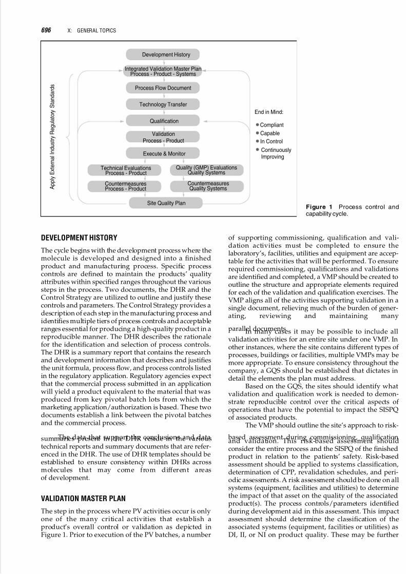
5/17/2018 13243184 Validation Part 8 - slidepdf.com
http://slidepdf.com/reader/full/13243184-validation-part-8 96/143
DEVELOPMENT HISTORY
The cycle begins with the development process where themolecule is developed and designed into a finishedproduct and manufacturing process. Specific processcontrols are defined to maintain the products’ qualityattributes within specified ranges throughout the varioussteps in the process. Two documents, the DHR and theControl Strategy are utilized to outline and justify thesecontrols and parameters. The Control Strategy provides adescription of each step in the manufacturing process andidentifies multiple tiers of process controls and acceptableranges essential for producing a high-quality product in areproducible manner. The DHR describes the rationalefor the identification and selection of process controls.The DHR is a summary report that contains the researchand development information that describes and justifiesthe unit formula, process flow, and process controls listedin the regulatory application. Regulatory agencies expectthat the commercial process submitted in an applicationwill yield a product equivalent to the material that wasproduced from key pivotal batch lots from which themarketing application/authorization is based. These twodocuments establish a link between the pivotal batchesand the commercial process.
The data that support the conclusions and datasummaries present in the DHR reside in the varioustechnical reports and summary documents that are refer-enced in the DHR. The use of DHR templates should beestablished to ensure consistency within DHRs acrossmolecules that may come from different areasof development.
VALIDATION MASTER PLAN
The step in the process where PV activities occur is onlyone of the many critical activities that establish aproduct’s overall control or validation as depicted inFigure 1. Prior to execution of the PV batches, a number
of supporting commissioning, qualification and vali-dation activities must be completed to ensure thelaboratory’s, facilities, utilities and equipment are accep-table for the activities that will be performed. To ensurerequired commissioning, qualifications and validationsare identified and completed, a VMP should be created tooutline the structure and appropriate elements requiredfor each of the validation and qualification exercises. TheVMP aligns all of the activities supporting validation in asingle document, relieving much of the burden of gener-ating, reviewing and maintaining many
parallel documents.In many cases it may be possible to include allvalidation activities for an entire site under one VMP. Inother instances, where the site contains different types of processes, buildings or facilities, multiple VMPs may bemore appropriate. To ensure consistency throughout thecompany, a GQS should be established that dictates indetail the elements the plan must address.
Based on the GQS, the sites should identify whatvalidation and qualification work is needed to demon-strate reproducible control over the critical aspects of operations that have the potential to impact the SISPQof associated products.
The VMP should outline the site’s approach to risk-
based assessment during commissioning, qualificationand validation. This risk-based assessment shouldconsider the entire process and the SISPQ of the finishedproduct in relation to the patients’ safety. Risk-basedassessment should be applied to systems classification,determination of CPP, revalidation schedules, and peri-odic assessments. A risk assessment should be done on allsystems (equipment, facilities and utilities) to determinethe impact of that asset on the quality of the associatedproduct(s). The process controls/parameters identifiedduring development aid in this assessment. This impactassessment should determine the classification of theassociated systems (equipment, facilities or utilities) asDI, II, or NI on product quality. These may be further
Development History
Integrated Validation Master PlanProcess - Product - Systems
Process Flow Document
Technology Transfer
Qualification
End in Mind:
Site Quality Plan
Compliant
Capable
In Control
ContinuouslyImproving
ValidationProcess - Product
Execute & Monitor
A p p l y E x t e r n a l I n d u s t r y R e g u l a t o r y
S t a n d a r d s
Technical EvaluationsProcess - Product
CountermeasuresProcess - Product
CountermeasuresQuality Systems
Quality (GMP) EvaluationsQuality Systems
Figure 1 Process control andcapability cycle.
696 X: GENERAL TOPICS

5/17/2018 13243184 Validation Part 8 - slidepdf.com
http://slidepdf.com/reader/full/13243184-validation-part-8 97/143
defined as critical or noncritical. User requirementsshould be defined within the VMP as a requirement forthe design, procurement, and construction of all new ormodified systems (equipment, utilities, and facilities),regardless of facility type. Along with the systemimpact assessment, the documented user requirementsestablish the basis for all subsequent commissioning andqualification activities.
The VMP describes the architecture of documen-tation assuring a facility operates in a qualified andvalidated state. The detailed protocols used to performcommissioning, validation and qualification activitiesshould not be included in the VMP, but should beconsidered as the documents developed in support of the VMP. The VMP is a single integrated description of the standards supporting valid operations.
As facilities, processes, and standards change, soshould the VMP. The VMP should not be viewed as apoint-in-time document linked to facility delivery, butrather as a “living document” that is effective throughoutthe lifecycle of the manufacturing capability described.As a living document, the VMP should be reviewed
periodically, at least annually, and modifications madeas needed.
The VMP, as outlined in the GQS, should contain ata minimum the following information: (i) the scope of theVMP, (ii) rationale for the validation plan design, (iii)alistof standards and procedures that govern the commis-sioning, validation or qualification process, (iv) theorganizational structure applicable to the validationprocess and roles and responsibilities for tasks in theVMP, (v) the sequence of commissioning, validation andqualification activities, (vi) a summary of systems (facili-ties, utilities, equipment), and processes to be qualified orvalidated, (vii) a description of the documentation formatand process for the VMP and its specified documents
(e.g., protocols, work plans, report summaries), (viii)references to planning and scheduling of validationactivities (e.g., work or project plans), (ix) timing forapplication of site change management, (x) timing forapplication of site deviation management, (xi) the processfor maintenance of the validated state, and (xii)references to existing documents, and subordinate vali-dation plans.
PROCESS FLOW DOCUMENTS
A PFD is a site-specific process summary document foran API (molecule) or finished drug product that details
the reaction scheme or product formula, process andequipment flow, unit operations, materials specifications,process ranges and supporting references. A GQS should be established to ensure uniformity of content betweenPFDs at the various sites. This GQS, along with theoversight of the Global Molecule Steward, ensuresprocess alignment between sites. Templates should bedeveloped in support of GQS requirements to ensureconsistency of content between sites. The site specificPFD should be developed early on in the transfer of aprocess from development or between manufacturingsites. The PFD may utilize data collected in the DHPand/or Control Strategy Document. The PFD should beused as the basis for developing batch production
records, performing PV, developing standard operatingprocedures, training, conducting nonconformance inves-tigations, and evaluating proposed changes. The PFDshould be considered a living document and revised asnew information is developed regarding the process. ThePFD should be reviewed at least annually to ensure itis current.
The PFD should include the following elements: (i)
a reaction scheme or product formula along with primarycontainer and closure components, (ii) the process andequipment flows (may be in flow chart form), ( iii) adescription overview of the manufacturing process, (iv)a detailed description of the unit operations involved inthe manufacturing process, (v) supporting rationale forspecifications for raw materials, intermediates, APIs, anddrug products, (vi) identification of CPPs and CFP andother control parameters and associated ranges with justification including supporting data, and (vii) therelevant regulatory registrations. All elements should becompared for consistency with the Regulatory Commit-ments outlined for that product or process.
CPPs are identified as those parameters that impact
the fitness for use of a process intermediate, API, or drugproduct if not maintained within specified limits. CPPsare parameters that, if not maintained within a specifiedrange, may have a detrimental effect on the products’CQA that cannot be overcome by control of other par-ameters further along in the process. CPPs are assigned tothose parameters that can most directly affect themolecule or product.
CFP are identified as those criteria that must be met before moving from one unit operation to the next.In-process materials that meet these requirements (e.g.,pH, potency) are suitable for forward processing to thenext subsequent unit operations. By definition, CFPs arecritical indications of proper process control. Operatingranges are values for process controls stated in the MasterFormula, and may be equal to but not greater than theProven Acceptable Ranges. A PAR is a range of values fora CPP or CFP documented as having no adverse affect onthe quality of process intermediates, API or drug product.A PAR may be supported by data from the DHR, ControlStrategy, historical data from batch records, laboratory orplant data, and/or statistically relevant data fromnonconformance investigations. PARs represent thedocumented envelope of acceptable performance.Operation in the range immediately beyond the CPPoperating range or PAR may produce material of signi-ficantly different quality.
The PFD also contains other parameters that arecontrolled within a process but are not identified ascritical in the document. These may include in-processcontrols, measurements, and/or checks of a product orprocess that contribute to the completion of a successfuloperating step and do not directly impact product qualityunder normal operating conditions. All process controlclassifications, whether a CPP, CFP or other processparameter should be justified within the PFD.
PFDs are product and site specific, meaning eachmanufacturing site shall develop a PFD for each molecule(API) or drug product manufactured at that site. Proces-sing ranges and PARs may differ between sites, but theidentified CPP and CFP for an individual molecule or
55: MANAGING VALIDATION IN A MULTINATIONAL COMPANY 697
5/17/2018 13243184 Validation Part 8 - slidepdf.com
http://slidepdf.com/reader/full/13243184-validation-part-8 98/143
product should be the same and independent of themanufacturing site.
TECHNOLOGY TRANSFER
Once the PFD for the manufactured intermediate, API, bulk drug product or drug product has been created andapproved, and the VMP is in place, the product is ready
for the Technology Transfer Process. According to theISPE, Technology Transfer is the systematic procedurethat is followed in order to pass the documented knowl-edge and experience gained during development and/orcommercialization to an appropriate, responsible, andauthorized party. Technology Transfer embodies notonly the transfer of documentation, but also includesthe demonstrated ability of a receiving unit to effectivelycarry out the critical elements of transferred technology tothe satisfaction of all parties and any applicable regulat-ory bodies. The ISPE Technology Transfer Guideprovided guidance throughout this section.
The formation of a team with cross-functionalrepresentation is the first step in the Technology Transfer
process. This team is charged with the responsibility toensure that the product is successfully transferred intothe manufacturing site. At a minimum, the team shouldconsist of a scientist and/or engineer from both thesending area and the receiving area, and representativesof the Quality Unit and Operations group in the receivingarea. Representatives of additional areas, such as labora-tory personnel, safety, and the sending area Quality Unitshould be named if necessary.
The first task of the cross-functional team is toconduct a gap assessment, which should include assess-ments of all areas deemed important to ensure asuccessful transfer. These areas include the facility itself,the utilities in the facility, the environment in the facility,the equipment needed and its qualification status, staffingcapacity and capability, and supporting areas such as thelaboratories. The gap assessments should be docu-mented, and action plans created for any identifiedgaps. When the gap assessments have been performedand documented, the team should create a formal Tech-nology Transfer Plan. This plan should include: (i) thetitle of the operation to be transferred, (ii) identification of the originating area and the receiving area, (iii) the reasonfor the transfer, (iv) the information to be transferred, (v)the scale-up production plans, (vi) any action plans stem-ming from the gap assessments, (vii) role s andresponsibilities for the team members, and (viii) a
proposed schedule for the process. Managementapproval of the Technology Transfer Plan should beobtained from both the sending and receiving areas.
After approval of the Technology Transfer Plan, theteam should prepare protocols for development batchand scale-up trial runs. The number of development runsor trials needed for transfer of a given process is flexibledepending on the complexity of the process and level of similarity between the sending and receiving siteprocesses and equipment. Demonstration batches arelots manufactured utilizing the intended commercialmanufacturing process to determine if the process iscapable of manufacturing material as designed. Eachdevelopment batch protocol should include: (i) the title
of the operation to be transferred, (ii) the purpose of thedevelopment batch, (iii) a description of the process, (iv) alist of the in-process tests that should be run and specifi-cations for each test, (v) a sampling plan, (vi) a list of theanalytical methods to be used, (vii) the acceptance criteriaand rationale for each sample and (viii) the intended use(marketable or not) of the batch. Each protocol should beapproved by a scientist and/or engineer from the sending
area, and a MS&T representative, Operations manage-ment and Quality Control management from thereceiving area.
The development runs should include a DOE toverify the critical parameter values. The DOE should be astatistically based experiment which is intended to verifythat the CPPs identified at the sending site are appro-priate with respect to the process as executed at thereceiving site. Design space experiments should beconducted as part of development of the full scalemanufacturing process, particularly with respect to estab-lishing PARs for CPPs and CFPs. These experimentsshould consider all of the various parameters thatimpact certain product attributes and how those par-ameters interact with one another.
A final report should be written for each protocol,which might contain data from multiple development batches. These reports should summarize the results of the run, and draw conclusions with respect to the processparameter ranges identified and any additional experi-ments that are required. Each scale-up report shouldinclude the approved protocol and the results and con-clusions of the executed batch, and should be approved by the same areas that approved the protocol.
Creation and approval of a Technology TransferReport signifies completion of the Technology Transferprocess. The Technology Transfer Report should include
the approved Technology Transfer Plan, the gap assess-ments and remediations that were performed, theapproved scale-up batch reports, and a summary of theprocess transfer including the results obtained, a summaryof any problems that were encountered and any associatedcountermeasures, and conclusions as to whether thetransfer was acceptable. The team leader of the TechnologyTransfer Team, Management from the sending area,Operations management from the receiving area, QualityControl management from the receiving area, and MS&Tmanagement from the receiving area should approve theTechnology Transfer Report. Qualification of the facilitiesand equipment in the receiving area should occur concur-rently with execution of the Technology Transfer Plan and
completed prior to approval of the Technology TransferReport.
QUALIFICATION
During completion of the Technology Transfer process,and prior to the initiation of PV, the utilities, equipment,and computer systems in the receiving area should beappropriately qualified. Ideally, qualification of thesesystems should occur as part of the technology transferprocess. Successful manufacturing facility, utility andequipment qualification is a necessary preconditionfor PV.
698 X: GENERAL TOPICS

5/17/2018 13243184 Validation Part 8 - slidepdf.com
http://slidepdf.com/reader/full/13243184-validation-part-8 99/143
There should be a GQS established for commis-sioning and qualification of facilities, utilities,equipment and computer systems, which ensures thatthe qualification process is consistent from site to sitewithin the company. The GQS should provide the generalrequirements for the major activities in the lifecycle of aGMP asset, such as: (i) assess impact, (ii) define require-ments, (iii) design, (iv) design test requirements and (v)
test and release. Each site should then create detailedlocal procedures describing how qualification activitieswill be performed at that site in accordance with the GQS.The GQS for qualification should be written such that if local procedures are compliant with the GQS, they willassure that the minimum regulatory requirements forqualification will be met for all markets.
Qualification is a four-step process consisting of DQ, IQ, OQ, and PQ.
DQ is an affirmation that the designs of DI systemsand GMP facilities are suitable for their intendedpurpose. DQ should occur after the user requirementshave been established and the detailed design has beencompleted, but prior to the fabrication or construction of
the DI system or GMP area. At a minimum, DQ shouldinclude identification of the DI systems and GMP areas,and should include documented assurance that thedesign of DI systems and GMP areas has incorporatedthe user requirements. The DQ protocol should definehow the user requirements will be met. DQ should alsoinclude a review of appropriate design documents suchas engineering drawings, process and instrumentationdiagrams, process flow documents, airflow and instru-mentation diagrams, software flow charts and any otherrelevant documents to ensure that user requirementshave been incorporated into the design.
IQ occurs after the DQ process is complete. IQ isdocumented verification that the systems (facility, utili-
ties, and equipment) as installed or modified, complieswith the approved design and with the manufacturer’srecommendations. The IQ process also consists of veri-fying the critical features and requirements identified inprocurement specifications including materials of construction, and includes verifying correct installationand location as compared to as-built drawings. The IQpackage should include the results of any testing orcalibration performed, analysis of the data, andsummary and recommendations.
OQ occurs after the appropriate technical andquality unit personnel have approved the IQ summarypackage. OQ is documented verification that the systems(facilities, utilities and equipment), as installed or
modified, perform as intended throughout the antici-pated operating ranges. The OQ protocol should definecritical parameters and specify acceptance criteria toverify that operating requirements can be met across thefull range recommended. These operating requirementsare identified in the User Requirements document. TheOQ protocol should test the entire range of normaloperating conditions for which the equipment is to bequalified. The OQ summary package should include: (i)documentation of all results and verification that theoperating ranges for critical parameters conform tothe user requirements, (ii) a summary and analysis of the data and any recommendations, (iii) verification thattraining requirements, supporting materials, and
procedures are available, (iv) preventative maintenanceplans, and (v) calibration and spare parts requirements.
PQ is the final stage in the qualification process. PQoccurs after the OQ summary package is approved. PQconsists of documented verification that the systems(facilities, utilities, and equipment), as integrated,including the in-feeds to and exit from the process, canperform effectively and be replicated based on the
approved process method and product specification. ThePQ process consists of testing critical equipment operatingparameters to evaluate conformance to acceptance criteriausing production materials, ingredients, or components tosimulate production. The acceptance criteria shouldinclude measurements of both machine performance andCQAs of the product. Substitutes or simulated productsmay beusedfor PQ if the rationale for doing so is includedin the PQ protocol. The final PQ package should includethe test results, verification that performance resultsconform to protocol requirements, data analysis, andsummary and recommendations.
Qualification should be viewed as a living process.Once qualified, appropriate control systems should be
implemented to ensure that facilities, utilities and equip-ment remain in a qualified state. These control systemsshould involve periodic reviews of the facilities, utilitiesand equipment, including analysis, summary andconsideration of the cumulative and combined effects of indicators such as deviations, change requests, criticalalarms, preventative maintenance data, analytical testdata and physical inspections. Re-qualification activitiesmight arise from change controls related to processchanges, instrumentation changes, equipment changes,changes in engineering controls, or information learnedduring the periodic reviews.
PROCESS VALIDATION
When the equipment, utilities, and facilities have beenappropriately qualified, and the process has beenadequately demonstrated, tested and understood theprocess is ready for validation (execution of the PVlots). PV is the documented evidence that the process,when operated within established parameters, canperform effectively and reproducibly to produce anintermediate, API, or drug product meeting its predeter-mined specifications and quality attributes. Execution of the PV lots should not be the only activity required todemonstrate that a process is validated. All of theactivities, as described in Figure 1, both before and after
the PV lots, should be considered critical components indemonstrating that a process is validated and will remainin such a state.
Expectations for PV should be defined in a GQS forPV. Each site’s local validation procedures must betailored to ensure that the fundamental requirements inthe GQS are satisfied. The PV GQS should provideguidance on the following aspects of PV: (i) validationapproach, (ii) types of validation, (iii) prerequisites tovalidation, (iv) PV study design, (v) protocol executionand final package completion and (vi) ongoing moni-toring of the state of PV. The GQS requirements should be tailored such that compliance with the requirements by local procedures will ensure that the regulatory
55: MANAGING VALIDATION IN A MULTINATIONAL COMPANY 699

5/17/2018 13243184 Validation Part 8 - slidepdf.com
http://slidepdf.com/reader/full/13243184-validation-part-8 100/143
requirements for PV for every market will be met ateach site.
Prospective Validation is validation that iscompleted prior to the commercial sale of the drugproduct. Prospective validation should be performedfor all new processes, for modified processes asdetermined by the change evaluation, and for processesdetermined to be operating outside of the previously
validated state. In exceptional circumstances, where aprocess is being revalidated and prospective PV isnot possible, it may be acceptable to validate theprocess via a protocol that is prospective in nature, but which allows release of individual batches priorto manufacture of all of the validation lots—this isconcurrent validation.
Concurrent validation may be acceptable for reva-lidation of existing products with infrequent batchproduction, or to validate rework (usually limited toAPIs) or reprocessing steps. Documentation require-ments for concurrent validation are the same as forprospective validation, but individual batches may bereleased on an interim basis prior to completion of all of
the validation lots. However, the combined validationdata for all of the validation batches manufactured priorto each individual batch must be documented in aninterim report and approved by the quality unit beforerelease of each batch. The interim report for the last batchin a concurrent validation exercise will include the datafrom all of the validation lots and will serve as thefinal report.
The process being validated must be representativeof the process that will be executed in routine commercialoperations. Batches of drug product made for PV should be the same size as the intended commercial scale batchesor drug products, and should conform to the CPPs, CFPs,and other control parameters and associated ranges
documented in the PFD. PV batches are typically manu-factured at the target value for CPPs. The PV should bestructured to mimic routinely encountered timeframeswithin the manufacturing environment, and all timelimits must be specified and justified based upon dataand the needs of the product.
The PV protocol should specify the number of process runs to be included in the validation. Thenumber of runs to be included is determined based onconsiderations such as the complexity of the process, thecomplexity of the validation design, and the magnitudeof the process change being considered. A minimum of three consecutive batches meeting both protocol accep-tance criteria and routine batch release criteria are
typically recommended for PV, however, FDA guidancedoes allow flexibility in determining the appropriatenumber of lots necessary for a given process.
In all PV activities, the need for stability studiesmust be evaluated, justified, and documented in thevalidation protocol or validation project plan. Placingthe validation lots on stability should be stronglyconsidered for process validation batches of newproducts, for transfers of existing products to new sites,and for rework or reprocessing methods.
In addition to the considerations identified above,following are the minimum elements that should beincluded in a PV protocol: (i) a description of the processand reference to the PFD, (ii) the intent of the project and
process validation study, (iii) a list of the equipment andfacilities to be used, (iv) a list of the analytical methodsneeded, (v)theCPPsandCFPs,(vi) theanalytical testing to be carried out, (vii) acceptance criteria (including productspecifications and acceptance criteria, in-process controlsand validation acceptance criteria, and acceptance criteriafor additional testing performed), (viii) a sample planand sample handling procedures, (ix) methods for
recording and evaluating results, (x) roles and respon-sibilities, and (xi) inclusion of or reference to a proposedtimetable. The PV protocol must be approved by manage-ment from the appropriate technical, quality, andoperations groups and by a development scientistfor validation of a new chemical entity.
Once the protocol is approved, the readiness of eacharea involved in the validation should be assessed.Execution begins when the assessments conclude thateach area is ready to proceed. The PV protocol must beexecuted as approved, and if there are results on PV batches not meeting the validation acceptance criteriaspecified in the protocol, the scientist responsible for thevalidation must assess the impact on previously released batches and on the PV itself, and should promptly notifyquality management.
When all of the PV batches are complete, a finalsummary report should be created, which includes all of the data generated on the PV batches. This summaryreport, along with the approved protocol and allsupporting documentation, becomes the PV package.The PV package should be approved by management of the technical, quality and operations groups. Once the PVpackage is complete, the product enters the “execute andmonitor” phase of the life cycle. The data generated andreviewed in the execute and monitor phase may providefeedback that a product or process must be revalidated, at
which point the process begins again.
EXECUTE AND MONITOR
Once the validation package has been reviewed andapproved, the focus shifts to executing and monitoringthe product/process at each individual site. Compliancewith in-process parameters gives an ongoing level of assurance that the process is in control and willproduce a consistent product that meets all final productsspecifications. Continuous monitoring of in-process par-ameters, and reacting to trends early, places the companyin position to understand, control and improve themanufacturing processes. Business processes should bedesigned for collecting and analyzing data and moni-toring of these process parameters.
The parameters that will be monitored may bechosen based upon a myriad of different variables. Forexample, the parameters may be selected from the sitespecific PFD, which details out the CPPs and CFPs.Additional parameters may be chosen from recent manu-facturing issues or trends that have been noted duringproduction. Continuous monitoring of process par-ameters allows one to detect and react to trendsearly, ideally before a process moves to an out of controlstate.
700 X: GENERAL TOPICS

5/17/2018 13243184 Validation Part 8 - slidepdf.com
http://slidepdf.com/reader/full/13243184-validation-part-8 101/143
TECHNICAL EVALUATIONS/COUNTERMEASURES
APRs are useful tools, as well as compliance require-ments, to review quality indicators of a product and itsmanufacturing process to determine if changes areneeded in specifications, manufacturing processes orprocess controls. The expectation for an APR should bethat it consists of a thorough evaluation of a product andits manufacturing process to determine if it is capable, in
a state of control, and has remained in a state of validation. In addition to the items listed in 21 CFR211.180 (e) (summary of the review of batch records,product complaints, adverse events, recalls, returnedgoods, salvage operations, and significant investigations),an APR should also include component failures, in-pro-cess test data, batch yields, and a registrationconformance comparison.
A GQS specifying the expectations for APRsshould be constructed to ensure that they are performedconsistently from site to site. The GQS should require, ata minimum, specification of the types of documents anddata to be included in the review, documentation of thefindings and conclusions, and the improvements ident-ified to resolve any issues identified. As the dataanalyses are completed and summarized, conclusionsshould be drawn regarding the state of process controland capability, validation status, and appropriateness of process controls and specifications. The conclusionsdrawn from these analyses can be used to driveimprovement activities for the process and product,and should be included in the final APR report. Basedupon these conclusions, recommendations should bemade regarding any activities required to return theprocess to a state of control or validation, if necessary.In addition, any inconsistencies that are discoveredshould be noted, with recommendations for resolution.
Corrective or preventive actions to address recommen-dations in the APR must be prioritized and tracked andshould be captured in the site’s CAPA system. Finally,the conclusions should be used to help ensure thatcontinuous improvement opportunities are identified.The APRs should be reviewed and approved by theGlobal Molecule Steward as well as the various sitefunctions (Quality, Manufacturing, and TechnicalServices). APR documents shall be site specific to aspecific product. To incorporate a global review forproducts manufactured at more than one site, theGlobal Molecule Steward may utilize the GlobalProduct Assessment. These documents, developed bythe Global Molecule Steward should be a compilation of
data analysis of the individual processes at each globalmanufacturing site to identify any trends, inconsisten-cies and opportunities for continuous improvementacross the supply chain for an individual molecule orproduct to ensure alignment between sites and toidentify any issues that are common to more thanone site.
A global team that may be utilized for monitoringof a product or process is the GPLOT. These teams shallconsist of members that globally support a particularproduct or process. At a minimum the team membersshall be the Global Technical Molecule Stewards (bothAPI and drug product), Global Analytical MoleculeSteward, Global Regulatory Steward, representatives
from the supply chain sites and statistician support.The team shall conduct meetings under the guidanceof a Project Manager. Other attendees may consist of medical, marketing, packaging or distribution. Themission of the team shall be to efficiently deliver theright technical projects in manufacturing, as defined by asound technical agenda which is driven by customerneeds and deep scientific understanding of the
products and processes. This is accomplished byproduct/process historical review, technical knowledgeand documentation.
QUALITY (GMP) EVALUATIONSAND COUNTERMEASURES
A quality system should be established to identify processissues (nonconformances) and address their root causes aspart of a holistic approach to PV, and to assure that aprocess remains in a validated state. A GQS should beconstructed which contains requirements to be used acrossall sites in identifying, reporting, investigating, managing,approving, and documenting nonconformances andimplementing effective corrective and preventativeactions. A CAPA system is one such initiative to addressnonconformances and eliminate or minimize recurrences.CAPA is a continuous improvement process which isdesigned to track and trend quality problems, identifytheir root causes, approve and take corrective and preven-tative actions to eliminate or minimize root causes, andmeasure the effectiveness of the actions taken.
Figure 2 depicts the life cycle of a nonconformancethrough the CAPA system. CAPA investigations areinitiated when a nonconformance or adverse trend isidentified. Investigations lead to actions to address the
existing problems (corrective actions), as well as actionsto address the underlying root cause (preventativeactions). Actions identified to prevent these nonconfor-mances or adverse trends from occurring/recurringshould be included in site quality plans or executed astechnical projects. Follow-up measures are put into placeto evaluate the effectiveness of theimplemented countermeasure.
The benefits to implementation of a CAPA systeminclude: saving time, resources, and money by addressingthe root cause of quality problems, eliminating recurrenceof quality problems, and reducing the number of qualityproblems. Implementation of a CAPA system shoulddrive the culture to become proactive rather than reactive,
where systems and processes are improved continuously.The CAPA system aligns with both regulatory expec-tations and industry best practices. By implementing aCAPA system, a business establishes a tool for correctingimmediate problems, understanding the root causes of problems, and identifying actions to prevent them from
Ide ntif ic at io n Inv es tigatio n Implem entation Evalua tion
Figure 2 System elements activity.
55: MANAGING VALIDATION IN A MULTINATIONAL COMPANY 701
5/17/2018 13243184 Validation Part 8 - slidepdf.com
http://slidepdf.com/reader/full/13243184-validation-part-8 102/143
recurring. Organizations that focus on continuousimprovement stay competitive by improving theirprocesses and their products. Without a focus on continu-ous improvement, organizations can find themselves in areactive cycle, correcting only their most immediateproblems.
SITE QUALITY/TECHNICAL PLAN
A site quality and technical plan is developed from theoutputs of the technical and quality evaluations. Thisplan should be a living document that is updated asadditional information is gathered.
SUMMARY
The key to successful validation at a multinationalcompany is defining the holistic global process to beused and through the use of strong GQS, templates,training and active oversight by qualified technical stew-ards. By developing the systems and tools required, awell integrated process for validation can be establishedthat allows all activities to occur quickly in a well planned
manner. The benefits of which are a deep process under-standing that focuses on continuous learning andimprovement with fewer costly production delays dueto unplanned technology transfer issues and unexpectedprocess failures.
702 X: GENERAL TOPICS

5/17/2018 13243184 Validation Part 8 - slidepdf.com
http://slidepdf.com/reader/full/13243184-validation-part-8 103/143
56
Validation in a Small Pharmaceutical Company
Stephen C. TaralloLyne Laboratories, Inc., Brockton, Massachusetts, U.S.A.
INTRODUCTION
The following chapter provides a perspective on ageneral approach to validation activities in a smallpharmaceutical company. As a small company with afocus on contract manufacturing, Lyne Laboratories hassuccessfully completed validation on numerous ANDAs,NDAs and OTC products. Our approach to validationmeets the highest industry and regulatory standards andhas consistently and effectively been used with small,
large and virtual pharmaceutical companies. For LyneLaboratories and other small companies, validation is both challenging and rewarding. While it often taxesresources and demands intense and broad-basedmanagement involvement, it can also stimulate peakperformance from the team and individuals within thecompany. As a crucial component in pharmaceuticalmanufacturing, managing the validation process requiresleadership skills in addition to technical and scientificcompetency.
Validation principles date back approximately 30years, and yet, even today these principles remain astandard for all new manufacturing processes. Withadvanced technologies, the scientist has been afforded
more accurate means to accomplish these activities. Thishas greatly improved the quality process and therebyprovided better scientific data.
Pharmaceutical companies of all sizes typicallydedicate considerable resources, in terms of time,money and specialized personnel, to validate a cGMPfacility or process. The regulatory agencies, appropriately,do not distinguish or make exceptions in terms of validation for small companies versus large companies.For a small pharmaceutical company, technical andfinancial resources will undoubtedly be challenged. Inmany cases, resources outside the company may be calledupon to complement existing skills. Balancing internaland external resources is essential in order to maintain
ultimate control and responsibility for the overall process.This can be overwhelming to a small company or plantwith limited resources, so it is important to structure thevalidation team carefully. Leaders of small pharma-ceutical companies must realize that process validation
is critical not only to meet regulatory requirements, but asa tool for evaluating the entire process from the supply of API to ensuring that the drug product meets its intendedstability parameters. Validation in a small company isalso an excellent management tool for developing theknowledge and skills of key personnel.
The design, construction, commissioning, and vali-dation of pharmaceutical facilities and processes posesignificant challenges for project managers, engineers,and quality professionals. Constantly caught in the
dilemma of budget and schedule constraints, they haveto deliver an end product that complies with all building,environmental, health and safety governing codes, laws,and regulations. The process must also comply with onevery important criterion; it must be validated to meetcGMP regulations.
The cost of validation is determined by time spenton documentation, development of protocols and SOPs,and time spent on actual fieldwork, data collection andanalysis. Often, varying validation practices and method-ologies result in inefficient implementation and costlydelays. Too often, the validation process reveals a large burden of unfinished commissioning business, resultingin a delay in start-up.
In some cases, validation is carried out but involvesa limited number of personnel within the organization.This lack of information sharing increases the misunder-standing of a manufacturing process by the mostimportant people within the company—manufacturingand quality personnel.
It is easy to lose sight of overall objectives during thevalidation cycle. Companies can get very focused on thescientific aspect of pharmaceutical manufacturing andforgetthat it is a business. A company must run efficiently,produce quality products and meet the demands of themarketplace. Validation data should provide the baselineinformation, which will become the reference data and
parameters for a given product during the product’slifecycle. The emphasis for the validation process should be to develop as much information before, during andafter validation since the process is not likely to changeduring the product’s lifecycle. A product process isevaluated annually to assess any changes or annualtrends that may force the process out of control. This ispart of the cGMP annual product review and ISO 9000annual product review.
With potential limitations on technical, financialand staffing resources placing pressure on the organiz-ation and process, successful validation at a smallpharmaceutical manufacturing company requires greatplanning, organization and vision. When the entire
Abbreviations used in this chapter: ANDAs, Abbreviated New DrugApplications; API, active pharmaceutical ingredients; cGMPs,current good manufacturing practices; GMP, Good ManufacturingPractice; HVAC, heating, ventilation and air-conditioning; IQ, instal-lation qualification; NDAs, New Drug Applications; OQ, operationalqualification; OTC, over-the-counter; PQ, performance qualification;QA, quality assurance; R&D, Research and Development; SOPs,standard operating procedures.
5/17/2018 13243184 Validation Part 8 - slidepdf.com
http://slidepdf.com/reader/full/13243184-validation-part-8 104/143
company is aware of a new process startup and allparticipants are trained in their respective areas of expertise, validation can proceed smoothly and addvaluable information, knowledge and processes toan organization.
VALIDATION PLANNING
The scope of validation work needs to be developed earlyin the project to help facilitate the writing of a ValidationMaster Plan. Validation planning allows the projectand validation managers to prepare resource andscheduling requirements, and ensures that design engin-eer specifications and detailed design are suitable forvalidation.
The Validation Master Plan should be designed toencompass all facets of validation activity that thecompany expects to employ at present and for futurevalidation activities. The Plan should be a structured,detailed record defining all the testing, acceptance criteria,and documentation required to satisfy the regulatoryauthorities and support the validation process. Based onan impact assessment, the plan will also clearly define thescope and extent of the qualification or validation process by listing the matrix of products, processes, equipment, orsystems affected.
The Validation Master Plan applies to all facilities,equipment and processes that are subject to requirementsof cGMPs. This includes but is not limited to facilities,process utility systems, manufacturing and finishingequipment, analytical equipment, calibration, test equip-ment and computer-related systems.
The Validation Master Plan assigns responsibilitiesfor developing and executing validation program activi-ties, and gives a first look at an anticipated testing
execution schedule. There are many variables that must be taken into consideration during the planning process.For example, a small pharmaceutical manufacturingcompany must determine whether outside analyticaltesting laboratories will be used because that willusually add significant time to the schedule.
At the inception of a project, it is necessary, and infact essential, that the project team and project sponsorapprove the Validation Master Plan to enable the releaseof sufficient financial and staffing resources to support theentire project.
The Validation Master Plan should include thevarious technical support personnel within thecompany who will have direct responsibility for facetsof the Validation Plan. By means of a GMP audit, forexample, early involvement by QA should provide clearcommunication of regulatory requirements, ensuring thateffective procedures and practices are established upfront for incorporation into the project. Since validationactivities assess the critical aspects of a given manufac-turing process, the development department, from bench,pilot and scale-up, should be focused on a successfulprocess transfer. At the start of process development, thefocus should be on the commercial scale-up process. Thiswill minimize the potential for problems during tech-nology transfer and manufacturing of scaled upengineering batches.
A Validation Master Plan could include some of theitems listed below:
Building Design and construction
HVAC Design and IQs
Process water Design, IQ
Utilities Electricity, gases, steam,
refrigeration, design, IQs
Process equipment Design, construction,
installation, OQ
Laboratory Analytical and microbial
validation methods
Product process Validation
The key to successful project implementation is awell-defined project scope, which enables the validationteam to determine the degree of effort and level of resources required, enabling them to focus on itsdefined responsibilities. It is the function of the facility,equipment, or utility that determines what level of commissioning and qualification are needed. Developingthe project commissioning and validation scope is
normally accomplished by conducting a risk analysis orimpact assessment, whereby the impact of a system onproduct quality is evaluated, and the critical componentswithin those systems are identified (Fig. 1).
These are some of the critical areas that need to beconsidered when writing a Validation Plan:
IQ
The documented verification that an equipment/systeminstallation adheres to approved specifications andachieves design criteria. IQ documentation and protocolsare developed from process and instrumentationdiagrams, electrical drawings, piping drawings, purchasespecifications, purchase orders, instrument lists, engin-eering specifications, equipment operating manuals andother necessary documentation.
OQ
The documented verification that the equipment/systemperforms per design criteria over all defined operatingranges. Systems and equipment must function reliablyunder conditions approximating those of normal use.Draft SOPs must be prepared for the operation of each system and piece of equipment, if applicable.Those procedures are to be finished and formallyapproved after completion of the PQ evaluation of each system.
Process PQ
The purpose of PQ is to provide testing to demonstratethe effectiveness and reproducibility of the equipment,system or process. In entering the PQ phase, it is under-stood that the equipment has been judged acceptable onthe basis of suitable installation and operational studies.Critical operating parameters must be independentlymeasured and documented in each trial. Equipment,systems or processes should perform as intended, withexpected yields, volumes, and flow rates as described inappropriate SOPs. Components, materials and productsprocessed by each system or piece of equipment shouldconform to appropriate specifications.
704 X: GENERAL TOPICS

5/17/2018 13243184 Validation Part 8 - slidepdf.com
http://slidepdf.com/reader/full/13243184-validation-part-8 105/143
Product PQEstablishing confidence through appropriate testing thatthe finished product produced by a specified processmeets all release requirements for functionalityand safety.
Prospective ValidationValidation conducted prior to the distribution of either anew product, or product made under a revised manu-facturing process, where the revisions may affect theproduct’s characteristics.
Retrospective ValidationValidation of a process for a product already in distri- bution based upon accumulated production, testing andcontrol data. Technically, there is no such thing asrevalidation since it always involves a current process.Retrospective validation provides an opportunity toverify that the process remains in control and on target.
ValidationEstablishing documented evidence, which provides ahigh degree of assurance that a specific process willconsistently produce a product meeting its predeter-mined specifications and quality attributes.
Validation Protocol/PlanA written plan stating how validation will be conducted,including test parameters, product characteristics, pro-duction equipment, and decision points on whatconstitutes acceptable test results.
Worst CaseA set of conditions encompassing upper and lowerprocessing limits and circumstances, including thosewithin SOPs, which pose the greatest chance of processor product failure when compared to ideal conditions.
Define Process
RequirementsSpecifications
Equipment
Procedures
Define SystemSpecifications
Equipment
Procedures
Define ProcessDesign/Specify
Equipment
Qualify Equipment
Review ProcessCapability
Specifications
EquipmentProcedures
Develop ValidationProtocol
Data
Validation Report
Acceptance
Ongoing ProcessEvaluation
DevelopSpecifications
Procedures
Install Equipment
VerifySpecifications
Procedures
Qualify Equipment
Develop Validation
Protocol
3 Validation Lots
New/Revised Process /
Product
Existing Process/Product
3 Validation Lots
Figure 1 Validation processschematic.
56: VALIDATION IN A SMALL PHARMACEUTICAL COMPANY 705

5/17/2018 13243184 Validation Part 8 - slidepdf.com
http://slidepdf.com/reader/full/13243184-validation-part-8 106/143
Such conditions do not necessarily induce product orprocess failure.
Process ValidationEstablishing documented evidence that provides a highdegree of assurance that a specific process will consist-ently produce a product meeting its predeterminedspecifications and quality characteristics. Process Vali-
dation will include acceptable release testing of not lessthan three batches that meet the processing limits for allcritical parameters.
Analytical Method Development ValidationDemonstrating that the analytical procedure is suitablefor its intended purpose. A tabular summation of thecharacteristics applicable to identification, control of impurities and assay procedures should be included inthe method validation.
Cleaning ValidationEnsuring cleaning effectiveness through a cleaning vali-
dation program that includes initial cleaning of newequipment and postbatch cleaning. Cleaning methodsare developed and qualified to show that residuals or by-products from manufacturing and cleaning have beenremoved. Swab and rinse samples are collected frompoints identified in the cleaning validation protocolsand analyzed using a qualified method. Validation of postbatch cleaning procedures includes acceptableresults from not less than three batches.
VALIDATION TEAM
Management of the validation process is key to control-
ling the cost and time of validation. Pharmaceuticalcompanies typically require considerable resources interms of time, money and personnel to validate. In asmall pharmaceutical company, a critical part of mana-ging a validation project is the selection of personnel fromwithin the organization to participate in preparing andexecuting the Validation Plan. Therefore, fundamentalproject management principles should be considered,with the primary objective to identify a project manager.It is essential that this individual have strong leadershipskills and be capable of directing and motivating others.This individual must have a good understanding of cGMPs, pharmaceutical manufacturing processes andgood communication skills in order to interact with the
various team members and departments withinthe organization. The project manager will constantly bechallenged by monitoring performance, meeting dead-lines, costs, scheduling and rescheduling variousactivities and will need to outline the project activitieswith anticipated timelines in order for the project toproceed efficiently. Delays, communication problems,poor coordination of activities are just some of theproblems, which may be encountered.
The Project Team should be structured appropri-ately, and roles and responsibilities clearly defined. Teammembers should be knowledgeable about validation withparticular emphasis on the areas that they represent. Theeducational backgrounds of personnel involved with
validation work are varied and may range from phar-macists, chemists, and microbiologists, to chemicalengineers, process engineers and others. The need foremployees with diversified backgrounds is understand-able. However, the validation group’s responsibilitiesrequire a complete understanding of technical equip-ment, equipment controls, electronics, laboratoryinstrumentation and testing and product sampling and
testing. Team members will have to balance daily activi-ties with new added validation responsibilities.Some of the departments involved in validation and
their responsibilities are as follows:
Research and DevelopmentResponsible for formulation development activities thatinclude formulation ingredients listing and concen-trations; process optimization, equipment types andfacility requirements; raw material and packaging com-ponent specifications, as well as product specifications.
RegulatoryResponsible for assessing the regulatory requirements toimplement a new process. Typically validation activitiesare required due to a new product under regulatoryreview by a regulatory organization. It will be necessaryto interpret global regulations and standards to obtainglobal marketing authorization.
Quality Control/Analytical LaboratoryResponsible for preparation of SOPs related to testing of raw materials, in-process samples, bulk drug product,finished drug product, cleaning validation samples,product process validation samples and stability studies.
Engineering
Responsible for participating in the design and installa-tion of a new facility and/or equipment; preparation of SOPs for maintenance and set-up of equipment once theequipment is qualified and the process validated; andproviding technical support for postvalidation activities.
Logistics/Material ControlResponsible for ordering materials used for the manu-facturing of prevalidation and validation batches.Preparation of SOPs for purchase specifications, iden-tifying and maintaining supplier profiles and evaluatingtheir performance during the product life cycle.
ManufacturingResponsible for the design of the facility and equipmentrequired for the manufacturing of the product to bevalidated; works closely with R&D during the develop-ment and optimization of the manufacturing process; andis responsible for all SOPs related to the manufacturingprocess.
Quality AssuranceResponsible for review and approval of all SOPs requiredfor all activities from IQ through process validation,as well as cGMP auditing of all activities related to theentire project including facilities, equipment, analytical,manufacturing and validation; approves the validation
706 X: GENERAL TOPICS

5/17/2018 13243184 Validation Part 8 - slidepdf.com
http://slidepdf.com/reader/full/13243184-validation-part-8 107/143
report, ensuring that the validation process meets itsintended criteria.
At times, it may be necessary for a small pharma-ceutical company to seek outside resources due totechnical expertise limitations and/or financial reasons.Finding the correct resources outside the company will insome instancesprevent problems anddelays. It maynot beas simple as identifying and engaging the services of a
single consultant, but rather engaging a consulting firmwith varied staff that can support manufacturing, cGMPauditing, documentation and validation writing. In othercircumstances, it may be more prudent to bring in avalidation expert consultant to direct the team anddelegate responsibilities within the staff. In either case,thekey is for management to maintain control of theentireprocess and ensure that outside resources are comp-lementary and accountable to thehead of the project team.
Identifying and selecting consultants adds value aswell as time to the validation process. If possible, a smallmanufacturing company should strive, as a regularcourse of business to regularly network and becomeknowledgeable about the available expertise in the
marketplace. Developing and maintaining industrycontacts can save significant amounts of time when anoutside resource is needed to supplement those alreadywithin the company.
DOCUMENTATION
The documentation required during validation organiz-ation is paramount to the success of the validation plan.The types of documents required range from qualificationto process validation and include analytical testing docu-ments and standard manufacturing and packagingdocuments. All of this information is requisite to theexecution of the validation plan; any void will result indelays with poor integration of data. Typical documen-tation for the qualification (IQ/OQ) of a facility or building might include protocols that define the testprocedures, documentation, references and acceptancecriteria that will establish that the facility has metintended qualification.
In order to streamline the validation process, thevalidation team will need to perform gap analysis todetermine the required documents. Technical infor-mation should become available to the team as detaileddesign proceeds. This enables the team to begin devel-oping a schedule of activities, staffing schedules,validation protocols, sampling plans, test plans and
training materials.Approaches to streamline the amount of paperworkrequired to give sufficient documented evidence of vali-dation could include:& Standardizing protocols and report templates wher-
ever possible, so that reviewers become used toprotocol formats and contents.
& Structuring executed protocols as reports to preventthe need for writing a separate report.
& Combining IQ and OQ documents, resulting in fewerdocuments to develop, review and approve.
& Validation acceptance criteria should be established based upon process capabilities and thereby meetingproduct quality standards.
& Establishing unrealistic acceptance criteria will oftenlead to increased work loads and cost overruns.
& Document all deviations. Attempt to determineassignable cause with a well-defined plan forcorrective action.
& Ensuring that commissioning documentation forprocess systems are planned, structured, organizedand implemented so that they may become an integralpart of the qualification support documentation.
Examples of qualification (IQ/OQ) documentsrequired:& Building Installation& Building Utilities—electrical, plumbing& HVAC& Compressed Air& Utility Piping& Process Piping& Filling Equipment& Packaging Equipment& Process Equipment& Analytical Instrumentation
Examples of process validation documents
required:& Standard Compounding Instructions& Standard Packaging Instructions& In-Process Testing Documents& Finished Product Testing Documents& Cleaning Procedures& Cleaning Validation Protocols& Analytical Testing Documents& Sampling Protocols
VALIDATION IMPLEMENTATION AND EXECUTION
In order to meet the intended objectives of a successful
validation plan, scheduling for validation is critical andoffers a significant challenge to the project manager. Sincemany departments of a small pharmaceutical companyare involved with the validation plan, the projectmanager must prepare and organize the activities wellin advance so that adequate time is allocated to meetmilestone targets. The project manager will need todevelop integrated schedules with direct input fromteam members to ensure everyone remains committedto meeting the overall timeline. Leadership becomes avery important aspect of project management during theimplementation period. Clear, effective and unwaveringdirection is required for successful validation.
There is constant change during the project lifecycle
especially if it involves construction and/or new equip-ment purchases. The project manager will need toidentify, track and coordinate the changes. It may be necessary to establish a strategic meeting scheduleto discuss such changes with the validation team. Thiswill undoubtedly lead to changes in the master timelineand possible delays, if the project manager has not addedextra time to the schedule in anticipation of such delays.Of course it is impossible to predict where the delaysmight occur, but good planning before initiating activitiesshould minimize the downtimes.
It is recommended that all systems go through ashakedown or debugging phase before beginning quali-fication activities. This should improve the efficiency of
56: VALIDATION IN A SMALL PHARMACEUTICAL COMPANY 707

5/17/2018 13243184 Validation Part 8 - slidepdf.com
http://slidepdf.com/reader/full/13243184-validation-part-8 108/143
transitioning from IQ to OQ activities and will help toreduce the number of changes required during thequalification phase. Typically the last phase of qualifica-tion, a performance qualification is usually the part of thevalidation program where product is produced on a largescale before engineering and commercial validation batches are produced. Because of the importance to theoverall plan, the project manager should allocate suf-
ficient time to the qualification activities which include, but are not limited to, equipment setup and maintenance,equipment outputs, equipment cleaning, and personneltraining.
As previously mentioned, it is important to assessinternal resources at the beginning of a project to scheduleactivities appropriately, especially in terms of analyticaltesting. A small firm may be overwhelmed by the amountof test samples and commitment time required to analyzesamples. Contracting with an outside analytical testinglaboratory to back up the primary analytical laboratorywill reduce delays with respect to validation testing andoverall timelines, but can add up to three to four monthsto the schedule, for the most part related to methods
transfer. This will only pose a problem if it is notaccounted for early in the planning and schedulingprocess. At the same time, validation costs will increase because it will be necessary to transfer the methods to anoutside laboratory before validation test samples can beanalyzed. The transfer procedure can be performed earlyin the project cycle after the methods have been validated,so that the contract laboratory will be ready when thevalidation project begins. If the manufacturer does nothave an analytical department, it may be cost effective toutilize the laboratory that developed and validated themethods to reduce redundant activities and added delays by searching for a new laboratory. In either case, theproject manager will need to ensure that timelines accom-
modate a need for external resources.
CONCLUSION
As stated in the introduction, validation principles are atool that, if applied properly, will result in a significantamount of scientific data for a given manufacturingprocess. A validation program should be a baseline forthe industrial pharmaceutical scientist to use in trackingthe process output throughout a product’s lifecycle. Forsmall pharmaceutical companies without the resourcesavailable at large companies, a well-organized validationplan is essential to a smooth, cost-effective process. Thefocus of the validation project manager should be to:1. Prepare and define the overall validation activities for
both management and the validation team members.2. Structure the activities in order to integrate them into
the overall organization without disruptingdaily operations.
3. Identify the most competent and team-oriented indi-viduals within the organization and make them partof the validation team.
4. Complete the project on time and within budget.
These four steps will ensure the validationprogram not only is successful, but becomes part of thecompany’s standard routine. At the same time, it iscritical that the resources and responsibilities for imple-menting the program be committed to an individualwho can oversee, manage, schedule, coordinate, commu-nicate and interact with a group of professionals from both within and outside the company. The skills associ-
ated with this are not necessarily technical, but rather business savvy and leadership skills, allowing oversightand management of both the financial and technicalresources for a given project. The ultimate responsibilityas far as the regulatory agencies are concerned remainswith the company—whether large or small—so it isessential that control of the business is maintained atall times.
BIBLIOGRAPHY
Carleton F, Agallaco J, eds. Validation of PharmaceuticalProcesses Sterile Products. 2nd ed. New York: MarcelDekker, Inc., 1999.
ISPE. GAMP Good Practice Guide: Validation of Process ControlSystems, 2003.Institute of Validation Technology. J Valid Technol 2004; 10(2).Institute of Validation Technology. J Valid Technol 2004; 10(4).Kropp M. Pharma’s continuing validation challenge: remedia-
tion for 21 CFR Part 11 compliance. Am Pharm Rev 2004;7(3):10–2.
Loftus B, Nash R, eds. Pharmaceutical Process Validation, Vol.23. New York: Marcel Dekker, Inc., 1984.
U.S. Department of Health and Human Services, Center forDrug Evaluation and Research. Guideline on GeneralPrinciples of Process Validation, May 1987.
U.S. Department of Health and Human Services, Food and DrugAdministration, Center for Drug Evaluation and Research.Chemistry, manufacturing, and controls documentation.Draft Guidance for Industry: Analytical Procedures andMethods Validation, August 2000.
U.S. Department of Health and Human Services, Food and DrugAdministration, Center for Drug Evaluation and Research.Pharmaceutical CGMPs. Guidance for Industry: PAT—AFramework for Innovative Pharmaceutical Development,Manufacturing, and Quality Assurance, September 2004.
U.S. Department of Health and Human Services, Food and DrugAdministration, Center for Drug Evaluation and Research.Pharmaceutical CGMPs. Draft Guidance for Industry:Quality Systems Approach to Pharmaceutical CurrentGood Manufacturing Practice Regulations, September 2004.
U.S. Department of Health and Human Services, Food and DrugAdministration, Center for Drug Evaluation and Research.Guidance for Industry: General Principles of SoftwareValidation—Final Guidance for Industry and FDA Staff,
January 11, 2002.U.S. Food and Drug Administration, Office of Regulatory
Affairs, Office of Regional Operation, The Division of Field Investigations. Guide to Inspections of Validation of Cleaning Processes, July 1993.
Wrigley G, du Preez J. Facility validation: a case studyfor integrating and streamlining the validation approachto reduce project resources. J Valid Technol 2002; 8(2):1–22.
Zaret E. The Value of Validation, Pharmaceutical Formulationand Quality, June/July, 2002:47–8.
708 X: GENERAL TOPICS

5/17/2018 13243184 Validation Part 8 - slidepdf.com
http://slidepdf.com/reader/full/13243184-validation-part-8 109/143
57
Regulatory Aspects of Validation
Terry E. MunsonPAREXEL International, Waltham, Massachusetts, U.S.A.
Other chapters in this book have described how tovalidate processes. This chapter explains the regulatoryaspects of validation. The intent of this chapter is to coverthe laws, regulations and guidance documents thatpertain to validation.
The definition of validation that will be used in thischapter is establishing documented evidence whichprovides a high degree of assurance that a specificprocess will consistently produce a product meetingits predetermined specifications and quality attributes.The emphasized terms are the key elements of validation.When regulatory bodies review studies, they are looking
for predetermined acceptance criteria, enough infor-mation to demonstrate consistency of the process andgood documentation practices have been used.
LAWS
Every manufacturer knows that failure to validatemanufacturing equipment and processes or analyticalmethods will result in regulatory action being taken by the FDA or other regulatory authorities. The basisfor the regulatory action is the Food, Drug and CosmeticAct in the U.S.A. and Directives in the EU.
The Federal FDA (Act), enacted in 1906, said
nothing about validation. In 1962, cGMPs became a partof the Act. Section 501(a)(2)(B) stated that “if it is a drugand the methods used in, or the facilities or controls usedfor its manufacture, processing, packing, or holding donot conform to or are not operated or administered inconformity with cGMP to assure that such drug meets therequirements of this Act as to safety and has the identity,and strength, and meets the quality and purity charac-teristics, which it purports or is represented to possess.”The Act required the Secretary to publish current goodmanufacturing regulations. This authority was delegatedto the Commissioner of the FDA.
The EU published Directive 75/319/EEC (productsfor human use) in 1975 and directive 81/851/EEC (veter-inary products) in 1981. These directives are the source of requirements for compliance with GMP, employment of Qualified Persons and repeated inspections by the
regulatory authorities. These directives were required to be adopted into the laws of all the EU member states.
None of the laws of the U.S.A. or EU indicate thatvalidation is required. The validation requirement wasincorporated into the mandated GMP regulations.
GMP REGULATIONS
cGMPs, Human and Veterinary Drugs was published inSeptember 1978 (1). The regulations are published in theCFR Title 21 Parts 210 and 211. In the regulations the term
validation is not defined and is only mentioned in foursections. The specific sections are related to computerdata validation, COA data validation, sterilizationprocess validation and analytical method validation.Reading the GMP regulations they contain works like“assure, adequate, appropriate, proof or suitable.” FDAhas used these words to mean the need to performvalidation studies to demonstrate that there is assurance,the procedure is adequate, time interval is appropriate orthere are suitable controls. For example, subpart F, Pro-duction and Process Control, section 211.100(a), states:“there shall be written procedures for production andprocess control designed to assure that the drug productshave the identity, strength, quality and purity they
purport or are represented to possess.” This is the basisfor process validation. Without validation studies howcan you prove that the process will consistently assure thatthe product will meet it specifications (1). This paragraphrequires that control procedures shall validate the per-formance of manufacturing processes.
The principles and guidelines of GMP for the EUwere published in Directive 2003/94/EC for humandrugs and Directive 91/412/EEC for veterinary drugsin 1991. The GMP principles and guidelines are moreexplicit than FDA guidance. While they are labeledas guidance they really represent the GMP regulationsfor the EU. Most of the process specific informationis given in the annexes to the main sections. The
EU guidelines give the acceptance criteria that areexpected for manufacturing processes and even forenvironmental monitoring. This is the major difference between FDA and EU requirements. Most of the verydetailed information is published in the 18 annexes of theGMP guide. Some of these annexes will be noted inthis chapter.
GUIDELINES
FDA guidelines come in a variety of forms. They can beformal guidance documents, both draft and final,proposed changes to the regulations, letters to the
Abbreviations used in this chapter: ANDA, abbreviated new drugapplication; API, active pharmaceutical ingredient; BPC, bulkpharmaceutical chemical; CFR, Code of Federal Regulations;cGMPs, current good manufacturing practices; COA, certificate of analysis; CPG, compliance policy guide; EU, European Union; FDA,Food and Drug Administration; ICH, International Conference onHarmonization; LVPs, large volume parenterals; NDA, new drugapplication; PQRI, Product Quality Research Institute; QA, qualityassurance; RABS, restricted access barrier systems; SOPs, standardoperating procedures; SVP, small volume parenterals.

5/17/2018 13243184 Validation Part 8 - slidepdf.com
http://slidepdf.com/reader/full/13243184-validation-part-8 110/143
industry and other documents. All of these documentsshould be used to determine how the FDA thinks abouta topic. This way if you decide to deviate from thethoughts in these documents you can prepare yourdefense for your ideas.
Formal Guidelines
Guidelines, in general, are issued by the FDA to explainhow to implement GMP regulations. GMPs, generally, areintended to specify “what to do”; guidelines will specify“how to.” Guidelines are generally issued without publicnotice. They are defined in section 10.90 of the title 21 CFRin which it is clearly stated that they are not legally binding: “Guidelines state procedures or standards of general applicability, that are not legal requirements butare acceptable to the FDA, or may follow differentprocedures or standards.A guideline may not be usedin administrative or court proceedings.as a legalrequirement.” The FDA has been placing more relianceon guidelines in lieu of using the “notice-and-comment,rule-making” procedure required by law. Guidelinessometimes become enforcement standards once theyreach the hands of federal investigators (2). The primaryissue is that guidelines are intended to define “adequate,appropriate or give assurance.” The key is that failure tofollow regulatory guidelines will result in questions as tothe adequacy of the processes and procedure use in yourfacility. Thus, if you are going to deviate from theguidance, then you need to have sufficient data to provethat you provide.
In April 1984, the FDA made available itsDraft Guideline for Submission of Supportive AnalyticalData for Methods Validation in New Drug Applications(3). The guideline was intended to “provide directionsand suggestions to drug applicants for the presentation of
data, assembly of information, and submission of materials to the FDA concerning regulatory specificationsand methodologies as required by 21 CFR 314.50(e).”
Methods validation was to be carried out after theNDA has been submitted, or it might be requested andperformed during phase III of the NDA. “Validation”(their quotation marks) may range from the “step-by-steprepetition of an assay procedure to more elaborate studiesthat include assessment of accuracy, precision, specificity,sensitivity, and ruggedness of the method and purity of reference standards.” Specific instructions were given forsample submission. “Samples of impurities, precursors,or degradation products must be submitted if limitspecifications exist, or if they are critical to the assessment
of the performance of assay or identity tests.” Theinformation requested included synthesis of the drug,synthesis of the reference standard, and tests for itspurity. Reproducibility day-by-day, laboratory-to-labora-tory, technician-to-technician, and column variabilitydata are required. This draft guideline left nothing tothe imagination, and even listed “examples of CommonProblems That Delay or Prevent Successful Validation.” Itwent into considerable detail on how to define a particu-lar high-performance liquid chromatographic column.The FDA provided a list of everything that was requiredwithout specifying the sources for obtaining this infor-mation. In 1995 a new guideline based on the ICHdocument Q2A-Test on Validation of Analytical Procedures
was published (4). That guideline indicates that the typeof analytical procedures that require validation areidentification test, quantitative test for impurities’content, limit test for control of impurities and quan-titative test of the active moiety in samples of drugsubstance or drug product. It goes on to indicate typicalvalidation characteristics to be studied, i.e., accuracy,precision including repeatability, specificity, detection
limit, quantitation limit linearity and range. There is a brief discussion of when revalidation is required. Thedocument also gives a very useful table indicating whichtests are required for identification methods, impuritymethods and assay methods. For example, for an identifi-cation test only the specificity characteristic of the methodis required while the assay method requires every testexcept detection limit and quantitation limit. In 1996, theICH and FDA published a companion document to Q2Aentitled Q2B Validation of Analytical Procedures: Method-ology (5). ICH Q2B gives more detailed information onfactors to consider in each of the test characteristic listedin ICH Q2A. Both of these documents represent therequirements for submitting analytical method validation
to applications and the minimum GMP requirements.In March 1986, an updated draft was issued on theGuideline on General Principles of Process Validation. Itwas not until May 1987 that the National Center for Drugsand Biologics and National Center for Devices andRadiological Health issued the final version of Guidelineon General Principles of Process Validation (6). The guidelinepresents FDA ideas on what it would look for duringinspections on matters concerning validation. The guide-line outlines the general principles that the FDAconsiders to be acceptable elements of process validationfor the preparation of human and animal drug productsand medical devices. A definition reads: “Process valida-tion is a key element assuring that quality assurance goals
are met although end-product testing plays a major role.Process validation is establishing documented evidencewhich provides a high degree of assurance that a specificprocess will consistently produce a product meeting itspre-determined specifications and quality charac-teristics.” It requires protocols, replicate runs, upperand lower processing limits, and evaluation of “worst-case” conditions. Systems used must be qualified. It refersto CFR paragraphs 211.100, 211.110, and 211.113 to justifythe need for validation. It identifies the elementsof Process Validation, Installation Qualification, andPerformance Qualification, which involved the creationof protocols, trials, analysis of data, and the issuanceand approval of reports. There should be a QA System
for revalidation when changes are made that couldimpinge on product characteristics. Documentationrequirements are outlined. It indicates that, with retro-spective validation, accumulated data and records of themanufacturing procedure are used. The data are statisti-cally analyzed to show what variance in the process can be expected. Process validation involves the analysis of test parameters to demonstrate that a specific processproduced a drug product that met predetermined specifi-cations and assured the standards of identity, quality,strength, and purity. Validation starts at the researchand development stage and continues until the productis approved for marketing. With products that were onthe market before validation guidelines were formalized,
710 X: GENERAL TOPICS
5/17/2018 13243184 Validation Part 8 - slidepdf.com
http://slidepdf.com/reader/full/13243184-validation-part-8 111/143
a retrospective validation could be applicable. With thisprocedure, the history of a production process could beapplicable. It requires a review of process records, in-pro-cess test data, finished product test data, rejection records,deviations, and investigations of failures and complaints.New data could be accumulated on a concurrent basis. Ithas been rumored that FDA is currently revising thisguideline for upcoming publication.
In July 2001, the EU published annex 15 to the GMPguide on Qualification and Validation (7). They indicatethat a risk assessment approach should be used todetermine the scope and extent of validation. This isone of the first times a regulatory body has specificallycalled for risk assessment tools to be used in validation.The document continues with a discussion of theelements of qualification and validation. It indicates thatfacilities, systems and equipment are qualified andprocesses are validated. In the qualification section itdiscusses design, installation, operational, and per-formance qualification. Under process validation theelements of prospective, concurrent and retrospectivevalidation are discussed. As with the FDA: retrospective
validation is reserved for well established processes andwould not apply to any process where recent changes incomposition of the product operating procedures orequipment has occurred.
In the early 1980s, with the advent of computerapplications in the pharmaceutical industry, duringmanufacture and testing, strong emphasis was placedon computer validation. In 1983, FDA issued a 25-page booklet, its “Bluebook”—A Guide to Inspection of Com- puterized Systems in the Manufacture of Drug Products (8).This is used by FDA investigators to cover the subject of cGMPs for Validation of Computer Systems. For the EUthe validation requirements for computerized system isgiven in annex 11 to the EU GMPs.
Additional documents concerning computer vali-dation are Compliance Policy Guidelines on Compu-terized Drug Processing (7132a.07 input/outputChecking; 7132a.08 Identification of Persons and BatchProduction/Control Records; 7132a.11; CGMP Applica- bility to Hardware and Software; 71232a.l2 VendorResponsibility; 7132a.15 Source Code for Process ControlApplication Programs) (9).
In March 1991, a revised Guideline on the Preparationof investigational New Drug Products was issued (10). Itaddresses the aspects of scaling-up from researchto commercial production and discusses recordretention requirements.
Bulk pharmaceutical chemicals (which were
not specifically covered by the 1978 revised GMPs) havealso come under the FDA’s inspectional reviews, and theFDA has started to apply GMP requirements to BPCmanufacturing, including validation of BPC processes.In 1991, the FDA issued an updated FDA Guide toInspection of BPC (11), which states “the purpose, oper-ational limitations, and validation of the criticalprocessing steps of a production process should beexamined.manufacturers will generate reports thatdiscuss the development and limitations of the process.The reports serve as the basis for the validation of themanufacturing and control process and the basic docu-mentation that the process works consistently”: purifiedwater systems must be validated. Bulk manufacturing
procedures can be validated with less arduousprocedures than would be required for finished dosageforms. In 1998 the FDA published the draft Guidance forIndustry Manufacturing: Manufacturing, Processing, or Holding API (12). This document incorporated all of theprevious GMP principles utilized for finished pharma-ceuticals to APIs. The major problem with the documentwas that it implied that the existing GMP regulations
could be directly applied to API manufacturing. The ICHtook up the subject of GMPs for API manufacturing.In August 2001 the FDA published Guidance for Industry:Q7A GMP Guidance for API (13). The objective of this document was to provide guidance regarding,GMP for manufacturing of APIs under an appropriatesystem for managing quality. Since the GMP regulationsdo not cover APIs, the document was developed to definethe application of GMP principles in the manufacture of APIs. The most significant aspect of this document is thatit outlines the requirement that the level of GMP appli-cation increases from the starting point of the process tothe final packaging of the finished API. The full appli-cation of GMP principles is required for the isolation/
purification processes, physical processes and packaging.Q7A indicated that sterile APIs must be validated inaccordance with the local requirements for sterile drugmanufacturing. The EU has also published the ICHdocument as annexe 18 to their EU GMPs (14).
In 1993 the FDA issued a CPG 7132c.08 (15) onprocess validation requirements for drug products andAPIs. CPGs are an internal guidance document that areintended for compliance officers in the FDA districtoffices. They are used to promote uniform enforcementof the GMP regulations between districts by indicatingthe minimum requirements for the subject of the guide.The guide followed the Guideline on Process Validation but added the requirement that three validation runs
were required for process validation. In March 2004 theFDA revised the guide to delete the reference to three batches at commercial scale as adequate minimum proof of process validity. They gave no replacement number. Inaddition it indicated that the term “validation batch”would no longer be used because validation should bepracticed using a “life cycle” approach. Both the industryand FDA focused too much on the absolute number of replicate runs and in doing so deviated from the originalintent of process validation which was to verify thedesign and development results. This meant that itcould be possible to reduce the number of commercialscale runs by having very good documented design anddevelopment data.
For terminally sterilized drug products verylittle guidance has been published by the FDA. In 1987the FDA published CPG 7132a.13 entitled “ParametricRelease—Terminally Heat Sterilized Drug products.” (16)It stated thatparametric release could be performed insteadof product sterility testing. It indicated that the sterilizationcycle must achieve a microbial bioburden reduction to 100
with a minimum safety factor of an additional 6 logarithmreduction. For parametric release the manufacturer mustidentifyall thesterilizationcycle parametersthat arecriticalandmonitor thecritical parameters. Because21 CFR211.167requires a laboratorytest for all sterileproducts andto makesure all of the product is subjected to the sterilization cycleeach truck of product was required to contain chemical or
57: REGULATORY ASPECTS OF VALIDATION 711

5/17/2018 13243184 Validation Part 8 - slidepdf.com
http://slidepdf.com/reader/full/13243184-validation-part-8 112/143
biological indicators. These constitute the laboratory testrequired in 211.167. If chemical indicators are used, theymust be able to integrate time and temperature to a reason-able degree. In July 2001 the EU published annexe 17 onParametric Release (17). They allowedparametric releaseof productsterilizedin their final container by steam, dry heatand ionizing radiation. Annexe 17 did not requirethe use of chemical and biological indicators.
In 1987 the FDA published the guideline on SterileDrug Products Produced by Aseptic Processing (18). Thiswas a significant document since for the first timeFDA indicated the minimum requirements for asepticprocessing of drug products. It indicated that asepticprocesses must be validated by running “media fills” of at least 3000 units and the acceptance criteria we set at0.1% with 95% confidence. In addition extensiveguidance was given on the environmental conditionsunder which the aseptic processes were to be executedand the environmental monitoring that was required.The guideline gave the cleanroom classifications wherevarious operations were to be performed, parameters fornonviable particulate sampling and limits for viable
particulates. Since 1987 great improvements have beenmade in aseptic processing. The industry has expended agreat effort to remove people from the process. This hasled to the use of isolators where people are completelyremoved from the process and RABS to minimize theintervention of personnel. In addition Form/Fill/Sealand Blow/Fill/Seal processes have been adopted toreduce the need for people to intervene into the asepticprocess. Because of these advances in aseptic processing,the FDA issued a concept paper on a new asepticguideline in September 2002 for comment. This docu-ment received extensive comments from the industry.The FDA took the major concerns the industry had withthe draft and sent them to the PQRI for resolution. The
PQRI which is composed of industry, academic and FDAexperts sent their recommendations back to the FDA inMarch of 2003. The final revised guideline waspublished in September, 2004 (19). This is the first timethere had been industry involvement in the developmentof an FDA guideline and has been considered verysuccessful from both the FDA and industry perspectives.The new guideline has a number of changes from the1987 version. The most significant are as follows:& The guideline indicated that aseptic manufacturing
of drug products should only be used when terminalsterilization is not feasible.
& A major effort was made to harmonize the envir-onmental requirements with other cleanroom
standards. For instance FDA adopted the ISO clean-room standards and many of the EU annexe1 requirements.
& Air velocity is no longer specified. Manufacturersmust justify the air velocity used. The 1987 versionindicated that the velocity must be 90 ft/minG20%. Drug manufacturers have argued for yearsthat there should be no set velocity and that therequirement should be that the velocity used should be that whic h is required to achieve properairflow patterns.
& Media fills are now called process simulations.This change was made because the industry focusedmost of its attention on the filling process and largely
ignored the other aseptic processes involved in drugmanufacturing. Appendix 3 to the guideline givesadditional information concerning aseptic processingthat occurs prior to filling and sealing operations. Itemphasizes the need to include these steps in theoverall validation of the aseptic process. The asepticprocess can be split into segments and each segmentcan be validated separately.
&
The acceptance criteria were changed from a con-tamination rate of 0.1% with 95% confidence to aset number of contaminated units no matter howmany units are filled. Basically, you are allowed0 contaminated units if fewer than 5000 unitsare filled. If 5000 or greater are filled, one wouldrequire an investigation and possibly a repeatprocess simulation run and two would require totalrevalidation of the aseptic process. An investigation isrequired if positive units are found.
& An appendix was added concerning the use of isola-tors for aseptic processing. Another appendix wasadded concerning Blow/Fill/Seal technology.
& The involvement of QA in the aseptic process vali-
dation received increased emphasis. QA wasspecifically required to observe the process simula-tions runs, including setup, and to perform orsupervise the inspection of the media filled vials.
The issuance of the Guideline for Submitting Docu-mentation for Sterilization Process Validationin Applications for Human and Veterinary Drug Products(20), in December 1993, has caused serious questioning onthe part of industry. The guideline presents filing rec-ommendations in NDA/ANDA submissions for thevalidation of sterilization processes, including moist heatterminal sterilization, ethylene oxide sterilization andradiation sterilization; stability considerations are alsoexpressed. The guideline requests information on things
such as bioburden, biological indicators, SOPs, container–closure integrity tests, floor plans, and others. Industry believes that preapproval inspections should be theprimary method to review sterilization process validation.Since sterility is seen as a major safety issue the debate withthe FDA is still continuing.
Proposed RegulationsIn June 1976, GMPs for LVPs were proposed (21). Theseproposed regulations were very explicit. Limits werepromulgated for lethality factors, the laminar flow of air, heat distribution, heat penetration, as well as forair and water quality. Although never approved,
they have had a significant effect on manufacturing andsterilization processes.In these proposed LVP GMP regulations, the word
“validation,” although cited, was not defined relative tosystems. In paragraph 212.182, it is used, generically, indiscussing “corrective action including validation of theeffectiveness of the action.” In paragraphs 212.243,212.244, and 212.245, sterilizer validation is outlined inspecific detail. The term validation was still undefined.
Many LVP and SVP manufacturers took heed andfollowed the suggestion that protocols were requiredusing scientific input from engineering, production, andquality control. To validate the basic systems would taketime, energy, and effort, plus the expenditure of resources
712 X: GENERAL TOPICS

5/17/2018 13243184 Validation Part 8 - slidepdf.com
http://slidepdf.com/reader/full/13243184-validation-part-8 113/143
to establish that the systems were “doing what theypurported to do.” Eighteen years after the publicationof these proposed LVP GMP regulations, they were nevermade final. One reason for their withdrawal was that allof the requirements had already become current GMP inthe LVP and SVP industry, so they were no longer needed.This is why it is important to read and understand evenproposed regulations.
In 1996 the FDA proposed other revisions to the GMPregulations (22). In their proposal the FDA indicated that based on its experience “more direction from the agency isnecessary because of the potential for harm, the narrowrange of acceptable means to accomplish a particular cGMPobjective, or to provide a uniform standard to the entireindustry. They also reiterate that the GMP regulations are based on three fundamental concepts of quality assurance:(i) quality must be designed and built into the product, (ii)you cannot test quality into a product and (iii) each step of the manufacturing process must be controlled to produce aquality product. In addition, they stated that the need forrevision was based on the following:& Rapid changes in technology&
Persistent lack of understanding of cGMP bysome manufacturers& Serious validation problems reveal that greater clarity
and specificity is neededThe proposed rule defined “process validation” as “a
quality assurance function that helps to ensure drugproduct quality by providing documented evidence thatthe manufacturing process consistently does what itpurports to do.” The key difference from the definition atthe beginning of this chapter is that it emphasized thatthere is a QA function to validation. In addition, methodvalidation is also defined as “.documented, successfulevaluation of an analytical method that provides a highlevel of assurance that such method will consistently yield
results that are accurate within previously establishedspecifications.” There is also a definition for “equipmentsuitability.” It is defined as “established capacity of processequipment and ancillary systems to operate consistentlywithin established limits and tolerances.” As stated earlierthis equates to equipment validation, because withoutvalidation how can you show that the equipment is“suitable.” Per the proposed rule reprocessing proceduresmust also be validated.
A key element in the proposed rule is that the qualitycontrol unit is responsible for reviewing changes inproduct, process, equipment or personnel and for deter-mining if and when revalidation is required. The FDAwants the quality control unit to be responsible for
insuring that the manufacturer evaluates its manufac-turing process, validates the processes and testing thatmust be validated and thoroughly assesses any discrepan-cies. The quality control unit must review and approve allvalidation protocols and reports. If the validation depart-ment is part of the quality control unit then someoneoutside the validation group must review and approvethe validation documents. The validation group cannotreview and approve their own work.
The other elements of the proposed rule merely putinto writing what the FDA had already been enforcing.There were no new ideas or requirements. The main issuewas that they were now put in writing instead of beingexpected requirements.
Letters to the IndustryIn October 1976, in a letter “to all manufacturers of injectable drugs” (23), the FDA noted that the validationof manufacturing processes was not limited to only single-dose. Assurance of product quality is derived from carefulattention to a number of factors including selection of quality parts and materials, adequate product andprocess design, control of the process and in-process and
end product testing. Each step of the manufacturingprocess must be controlled to maximize the probabilitythat the finished product meets all quality and designspecifications. Process validation is a key element inassuring that QA goals are met. It is through carefuldesign and validation of both the process and processcontrols that a manufacturer can assure that there is a veryhigh probability that all manufactured units from succes-sive lots will be acceptable. Successfully validatinga process reduces the dependence upon intensive in-pro-cess and finished product testing.
A definition is provided: “Process validation is adocumented program which provides a high degree of assurance that a specific process will consistently produce
a product meeting its pre-determined specifications andquality attributes.”
The FDA presented the idea “that the manufacturerprepares a written validation protocol which specifies theprocedures (tests) to be conducted and the data to becollected. The purpose for which data are collected must be clear, the data must reflect the facts, and the data must be collected carefully and accurately. The protocol shouldspecify a sufficient number of replicate process runs todemonstrate reproducibility.” The draft guidelinesproposed “a full challenge of the process.worst caseconditions.suitability of materials, the performance andreliability of equipment systems, buildings, and thecompetence of personnel.qualifications of each system.”The elements of process validation to be evaluated areenumerated: prospective validation (product specifi-cations, equipment and process, timely revalidation,documentation) and retrospective validation.
Other DocumentsCompliance Program C. P. 7356.002 (October 1978) definedvalidation: “a validated manufacturing process is onewhich has been proved to do what it purports to do” (24).The definition was dropped in the October 1982 Compli-ance Manual. The FDA offered the foregoing as onedefinition of validation. When the compliance programwas revised in February 2002 to conform to the new
system-based approach to inspections, most of theguidance information was removed from the program.Thedocument is still useful in that it indicates thevalidationissues thatinvestigators willwant to seeand arerequired toreview. For example in the Quality system the investigatorwill look to see that the quality control unit has responsi- bility for the status of required validation/revalidation. Inthe Production system they will look for the validation andverification of cleaning/sterilization/depyrogenation of containers and closures and process validation. Anothersubpart of the compliance program that gives moredetails concerning what is required is ComplianceProgram 7356.002A, Small Volume Parenterals (25,26),which provides additional information on validation.
57: REGULATORY ASPECTS OF VALIDATION 713

5/17/2018 13243184 Validation Part 8 - slidepdf.com
http://slidepdf.com/reader/full/13243184-validation-part-8 114/143
It encompasses recommendations for air quality, mediafills, sterility retesting, pyrogen testing, particulate matterdetection, water systems, and computer systems. An inter-esting aspect of this manual is that FDA personnel wereinstructed that the use of the term “inadequate,” whenemployed with reference to validation, is to be fullyexplained.
Other guidelines that may be applicable to validation
activities are:& Guide to inspections of Lyophilization of Parenterals& Guide to Inspections of High Purity Water Systems& Guide to Inspections of Microbiological Pharma-
ceutical Quality control Laboratories& Guide to Inspections of Sterile Drug Substance
ManufacturersThese guidelines can be obtained from the FDA
(www.fda.gov/cder).Since the inception of formal process validation with
the 1978 GMPs, simple validation issues of sterilizationprocesses have evolved, in a very complex manner, toinclude all aspects of pharmaceutical production. Everyphase of pharmaceutical operations, from bulk manufac-
turing to computer controls, from clinical manufacturingto full-scale production, have come under critical scrutiny.Detailed regulations and guidelines have been issued andupdated, and penalties for noncompliance have become both more frequent and severe. Process validation has become a very serious aspect of QA in the pharmaceuticalindustry. This chapter provides some indication of the many documents that are available concerning vali-dation. These documents should be used to make sure thatyour validation studies will be acceptable to regulatory bodies worldwide.
REFERENCES
1. Human and veterinary drugs, good manufacturing practicesand proposed exemptions for certain OTC products. Fed Reg1978; 43(part II):45013–45089.
2. Fry EM. Process validation: the FDA’s viewpoint. DrugCosmet Md 1985; 137(1):46–51.
3. FDA Communication. Draft guideline for submission of supportive analytical data for methods validation in newdrug applications, 1984.
4. International Conference on Harmonization, Q2A Test onValidation of Analytical Procedures, October 27, 1994, down-loaded from www.fda.gov/cder/guidance
5. International Conference on Harmonization, Q2B Validationof Analytical Procedures: Methodology, June 11, 1996, down-loaded from www.fda.gov/cder/guidance
6. FDA Compliance Guideline. General Principles of Process
Validation. May 1987.7. Annex 15 to the EU Guide to Good Manufacturing Prac-tice—Qualification and Validation, September 2001,downloaded from dg3.eudra.org/F2/eudralex/vol-4
8. FDA. Guide to Inspection of Computerized Systems in DrugProcessing, 1983.
9. FDA Compliance Policy Guideline. Computerized DrugProcessing Program 7132a.07 (October 1982), 7132a.08Identification of Persons and Batch Production/ControlRecords (December 1982), CGMP Applicability to Hardwareand Software 7132.11 (December 1984), Vendor Responsi-
bility 7132a.12, Source Code for Process Control ApplicationPrograms 7l32a.15 (April 1987).
10. FDA. Guideline on the Preparation of Investigational NewDrug Products (Human and Animal). March 1991.
11. FDA. Guide to Inspection of Bulk Pharmaceutical ChemicalsSeptember 1991 (reissued in December 1991).
12. FDA. Guidance for Industry: Manufacturing, Processing,or Holding Active Pharmaceutical Ingredients, March 1998.
13. FDA. Guidance for Industry: Q7A Good ManufacturingPractice Guidance for Active Pharmaceutical Ingredients,August 2001.
14. Annex 18, EU Guide to Good Manufacturing Practice,Medicinal Products for Human and veterinary Use, Part IIBasic Requirements for Active Substances used as StartingMaterials, 03 October 2003, downloaded from dg3.eudra.org/F2/eudralex/vol-4
15. FDA. Compliance Policy Guide Sec. 490.100 (7132c.08)Process Validation Requirements for Drug Productsand Active Pharmaceutical Ingredients Subject to Pre-
Market Approval (CPG 7132c08), 08/30/1993 and revised03/12/2004, downloaded from www.fda.gov/ora/compliance_ref/cpg/cpgdrg
16. FDA. Compliance Policy Guide Sec. 460.800 ParametricRelease—Terminally Heat Sterilized Drug Products (CPG7132a.13), October 21, 1987, downloaded from www.fda.gov/ora/compliance_ref/cpg/cpgdrg
17. Annex 17 to the EU Guide to Good Manufacturing Practice,Parametric Release, January 2002, downloaded from dg3.eudra.org/F2/eudralex/vol-4
18. FDA, Guideline on Sterile Drug Products Produced byAseptic Processing, June 1987.
19. FDA, Guidance for Industry, Sterile Drug Productsproduced by Aseptic Processing—Current Good Manufacturing Prac-tice, September 2004, downloaded from www.fda.gov/cder/guidance.
20. FDA. Guide for Submitting Documentation for SterilizationProcess Validation in Applications for Human and Veter-inary Drug Products. December 1993.
21. Proposed rules, human drugs, current good manufacturingpractices in manufacture, processing, packing, or holdingof large volume parenterals and request for commentsregarding small volume parenterals. Fed Reg 1976;41(100):22202–22219.
22. FDA. Current good manufacturing practice: proposedamendment of certain requirements for finished pharma-ceuticals. Fed Regist 1996; 61(87):20103.
23. Byers TE. Notice: To all manufacturers of injectable drugs,October 29, 1976.
24. FDA Compliance Program. No. 7356.002, Chapter 56, DrugProduct Quality Assurance, October 1978.25. FDA Compliance Program. No. 7356.002, Chapter 56, Drug
Manufacturing Inspections, February 1, 2002.26. FDA Compliance Program. No. 7356.002A, Small Volume
Parenterals, September 30, 1993.
714 X: GENERAL TOPICS
5/17/2018 13243184 Validation Part 8 - slidepdf.com
http://slidepdf.com/reader/full/13243184-validation-part-8 115/143
58
ValidationWhat’s Next?
James AgallocoAgalloco & Associates, Belle Mead, New Jersey, U.S.A.
INTRODUCTION
Validation has become ingrained in the healthcareindustry since the mid 1970s, when it was first intro-duced. Over the years the nature and scope of validationhas changed as it has been applied in a variety of situations. Given its maturity, it might seem possiblethat future changes in its application would be minimal.This chapter endeavors to explore future shifts in theindustry and how validation might be impacted by those
changes. The primary drivers for change in industry are:further advances in technology; a rapidly shifting regulat-ory environment; and the ever-present commercialconcerns of business.
TECHNOLOGY
In an industry like healthcare that is so dependent on newproducts, technological changes are ever present. Theelectronic age has not impacted our industry as dramati-cally as other industries, perhaps due to innateconservatism that is further reinforced by real (andimagined) regulatory constraints. Further changes
brought about by technology can be anticipated.
Automated Inspection/IdentificationRequirements for inspection of materials and verifica-tion of product attributes are myriad in our industry.For years these inspections have been performed manu-ally for in-process materials, labels and other items.Recognition that such inspections are slow, costlyand—perhaps most important of all—ineffective, appli-cations for machine vision for color, shape, fill, characterrecognition will dramatically increase. Systems formaterial identification including bar coding and radiofrequency will become more common. Validation of allof these systems will be built upon the proven methodsfor validation of automated particle inspectionincluding accept zone and reject zone efficiencies.Development of suitable validation sets and calibrationmethodologies for these technologies might representthe greatest challenge.
Process AutomationA review of literature over the last 20 years might suggestthat further automation in the industry is unlikely for lackof applications. One has only to visit a pharmaceuticalplant to realize that despite the publicity, that opportu-nities for automation abound. Validation of automatedsystems has been considered one of the more oneroustasks in the industry, and as a consequence implemen-tation has lagged. Progress towards full automation has been further slowed by the FDA’s guidance on electronicsignatures/electronic batch records (21 CFR 11) which hasperhaps caused more confusion than enlightenment (1).Millions of dollars have been expended in efforts to meetthe expectations of this regulation that has continued toevolve at the same time as firms have endeavored toadhere to it. Without definitive guidance on this subjecthigher level systems such as SCADA, MES, MRP II andothers are unlikely to penetrate this industry as rapidly asthey might. The validation of these systems is certainlypossible, provided the expectations are sufficiently clear.
RoboticsMany industries, automotive and microelectronics are
notable examples, have replaced personnel in repetitive,arduous or hazardous tasks with robots. Along with theirimplementation these industries have realized a consist-ency of performance unattainable by humans.
IsolationThe pharmaceutical industry first began to explore theutility of isolation technologies in the late 1970s forcontainment applications once the Toxic SubstancesControl Act mandated substantial improvements inworker protection for toxic and potent compounds (2).Applications foraseptic processing began only a fewyearslater when the first isolators for sterility testing were
introduced. Some 30 plus years later, these technologiesare increasingly commonplace for both situations, yetsurprisingly they are not considered cGMP requirements.In today’s risk-based compliancemodel it is safe to predictincreasing numbers of these installations, and thus anincreasing need to qualify and validate these systems asthey proliferate across the industry.
COMPLIANCE ISSUES
Process Analytical TechnologyThe FDA proposed and much of industry has embracedPAT as a means to increase product consistency through
Abbreviations used in this chapter: CFR, Code of Federal Regulations;cGMP, current good manufacturing practice; EMEA, EuropeanMedicines Evaluation Agency; FDA, Food and Drug Adminis-tration; ICH, International Conference on Harmonization; MES,manufacturing execution systems; MRP, materials resource plan-ning; PAT, process analytical technology; RFID, radio frequencyidentification; SCADA, supervisory control and data acquisition.

5/17/2018 13243184 Validation Part 8 - slidepdf.com
http://slidepdf.com/reader/full/13243184-validation-part-8 116/143
the use of in situ instrumentation that can confirm criticalproduct quality attributes while the material resideswithin the process equipment (3). Depending upon thefirm’s operating practices, PAT can offer either substantialoperational/quality advantages or have only minimalimpact on the firm’s operations. Firms that rely heavilyon stage-based in-process testing view PAT as a majoradvance over their current practices. Those firms that
have robust process controls including process validationin which in-process testing is limited, can expect minimal benefits. Inherent with the implementation of PAT is thequalification/validation of the instrumentation/controlsystem for use with each product. An expanded discus-sion of PAT and its validation appears elsewhere in thisvolume (see Chapters 48 and 49).
Risk-Based ComplianceAn FDA initiative in this area was first announced in2002, and a broadly worded guidance document wasissued in 2004 (4). This initiative has been recognized bythe global regulatory community, and harmonized
guidance can be expected. Some of the expectedoutcomes might include:& Increased emphasis on performance qualification
focusing on critical quality attributes.& A commensurate reduction in the installation/oper-
ational qualification activities that precede theperformance qualification.
& Greater attention on sterile products especially thosemanufactured by aseptic processing.
& Increased scrutiny of drugs formulations containingpoorly adsorbed drug substances.
That these and the other potential (and unfortu-nately only implied) changes in regulatory focus will alterthe structure of validation programs in many different
areas is near certain. The long-range impact of thisguidance is difficult to predict in a precise manner,though its projected effect is likely to be widespread.
HarmonizationThe global healthcare industry has been closely regulatedfor many years and has long been subject to differingrequirements in the various jurisdictions in which itoperates. In 1990, the ICH was formed as a joint activity between American, European and Japanese compendia,regulators and industry. The stated goal of this initiativeis to develop a uniform set of expectations for regulatoryand compendial for pharmaceuticals including: drug
registration, specification, testing, inspection, and post-marketing surveillance. The size of this effort is daunting,and while substantial progress has been made, a greatdeal of work remains to be done. Validation requirementshave been addressed in the areas of analytical chemistry, but only minimal progress has been made in areas relatedto systems and process validation. The differing inspec-tional models of FDA and EMEA have hamperedintegration of expectations especially in the areasof sterilization and aseptic processing. The differingexpectations of the device industry from those in thepharmaceutical arena, as evidenced in ISO standards,have slowed developments in many seemingly commonconcerns.
PackagingThe continued problems with labeling and packagingmix-ups reported in the FDA’s annual recall summariessuggests a need for increased attention to validation of packaging activities to better assure the supplied productis the desired product. That this has not received greaterattention is surprising. The automated inspection tech-nologies mentioned above can provide significant
improvements in this area. Implementation has acceler-ated in recent years in this area, but the recall datasuggests continued expansion of these systemsis required.
A growing regulatory concern is that of counter-feiting, in which the trade dress of the manufacturer is being mimicked by unscrupulous firms. As these itemsare being introduced into the global distribution system beyond the control of the phar maceutical firm, theresponses to this problem include unique identifiersin/on the packaging that are harder to imitate. Validationof these systems as a means of insuring patient safetyseems a near certain future result.
INDUSTRY ISSUES
Managing Validation and ChangeOne of the major challenges in today’s business isproviding means to maintain flexibility while remainingcompliant. Systems for the control of changes impactingany part of the validated process as required byregulation must be in place to assure the continuedacceptability of activities. The use of sophisticated docu-mentation management systems is becoming morecommon for the management of change and ensuringgreater compliance by regulation of document flow. Forlarger sites, these systems are perhaps the only effective
means to assure that changes are properly evaluated.
Perceived Excessive Costs of ValidationThere was a long-standing belief across the industry thatvalidation was little more than a regulatory requirementthat offered few economic advantages. This author heldthe opposite view; that validation could in fact lead tofinancial savings and other benefits (5,6). This perspectiveseemed remote at the end of the last century as bloatedqualification efforts seemed to be the order of the day.The FDA’s risk-based compliance initiative and economicrealities have fostered an emerging trend of recognitionthat properly managed validation as an inherently beneficial activity that does more than merely sate theinspector or reviewers expectations.
Contract OperationsRecent years have seen the greatly expanded use of contract manufacturers/packagers for a number of reasons. The changing business models now becomingprevalent suggest that this is no short-term trend.Systems and practices for coordination, execution andreview/approval of validation activities must be compa-tible with this reality. For firms with multiple contractsuppliers the management of these activities can becomequite complex. Effective tools for these multifacetedsituations are only beginning to emerge.
716 X: GENERAL TOPICS

5/17/2018 13243184 Validation Part 8 - slidepdf.com
http://slidepdf.com/reader/full/13243184-validation-part-8 117/143
CONCLUSION
Validation serves a supportive role in our industry, as itsprimary role is to confirm the acceptability of procedures,products, and systems. As these elements are in constantchange validation practices must change to accommodatethem. In the early 1970s when validation was firstconceived, biotechnology was in its infancy, the personalcomputer had not yet been invented, and RFID, ICH and
PAT were meaningless acronyms. Over 30 years later,validation practices have evolved to suit the changingenvironment in which it operates, and it should beevident that it will be able to accommodate futurechanges as well. That new factors influencing validationwill continue to emerge is near certain. What is equallycertain is that validation will adapt to work within thatnew environment as it has in years past. “The onlyconstant is change” (7).
REFERENCES
1. FDA, 21 CFR 11, Electronic Records; Electronic Signatures,2000.
2. EPA, 15 CFR 53, Toxic Substances Control Act, 1976.3. FDA, Guidance for Industry PAT—A Framework for Inno-
vative Pharmaceutical Development, Manufacturing, andQuality Assurance.
4. FDA, Pharmaceutical CGMPS for the 21st Century—A Risk-
based Approach, 2004.5. Agalloco J. The other side of process validation. J Parenter Sci
Technol 1986; 40(6):251–2.6. Agalloco J. Validation—a new perspective. In: Medina C,
ed. Compliance Handbook for Pharmaceuticals, MedicalDevices and Biologics. New York: Marcel-Dekker,2004:83–128.
7. Herodotus, The Histories, Circa. 430 BC.
58: VALIDATIONWHAT’S NEXT? 717

5/17/2018 13243184 Validation Part 8 - slidepdf.com
http://slidepdf.com/reader/full/13243184-validation-part-8 118/143

5/17/2018 13243184 Validation Part 8 - slidepdf.com
http://slidepdf.com/reader/full/13243184-validation-part-8 119/143
Index
AAMI/ANSI/ISO dose selection guidelines, 272–273Action level, 364–365Active air monitoring, 314Active air testing methods, 360Adhesives
denture, 421ostomy, 421transdermal, 421
Adventitious agents, 481–483Aeration, 284
chlorine dioxide and, 265, 266isolator decontamination and, 281–282
Aerosol, 351–355cans, 378
particle monitoring, 351–355isokinetic sampling, 352particle migration, 351–352sample point selection, 353–355transport tubing particle loss, 352–353
Affinity ligands, 470Air monitoring, 314Air removal, 203Air supply conformance, 229Air testing, 358
methods, 360–362active, 360passive, 360
Alarms, 465Alcohols, 307Aldehydes, 307Alert level, 364Alkylamine, 308Aluminum, 329Ammeter, 229Ampules, 374Anaerobes, 321Anaerobic monitoring, 366–367Analytical method validation, 594Analytical procedure validation, 655–663
assay characteristics, 656–657clinical development, 655–656marketed pharmaceuticals, 656
Antimicrobial preservative efficacy, 199API, 555–557Archiving data, 650
Aseptic assembly, 321–322Aseptic changing facilities
handling stoppers workflow, 15–16, 17layout development, 15–16
low traffic flow, 15separated flow in and out, 15
with garment reuse, 16Aseptic critical processing zones, 314–315Aseptic filling, 325
areas, 359media sterilization, 325placebo materials, 325
Aseptic processing validation, 319–325acceptance criteria, 324–325accountability, 324
[Aseptic processing validation]anaerobes, 321assembly, 321–322
bulk pharmaceutical chemicals and,327–332
campaign production, 323container selection, 321dosage forms, 323environmental monitoring, 322fill execution, 323growth promotion, 324incubation time, 322inert gassing, 321in-process media fills, 320–321
inspection of filled containers, 323–324interventions, 323line speed, 321manual filling, 321manufacturing, 322–323media fill
units, 324volume, 321
media runduration, 320frequency, 320
media selection, 321media sterilization, 319–320microbial identification, 324new facilities, 322product contact, 322sterile powders, 322–323study rationale and design, 319suspensions, 322
Aseptic processing, 678–679 buildings and facilities, 317–318
component preparation, 318critical areas, 318supportive clean area, 318
closures, 318–319components, 318–319containers, 318–319dosage form manufacture and, 317–326environmental monitoring, 325
microbiological, 325–326nonviable particle, 326
isolator technology, 326 Japanese validation methods and, 687–689manual, 333–337materials, 318–319personnel,
monitoring of, 318qualifications of, 318training of, 318
time limits, 319Assay, 396Assay characteristic validation, 656–657Assay variability control, microbial, 661–662
contamination, 661growth, 661–662recovery, 662

5/17/2018 13243184 Validation Part 8 - slidepdf.com
http://slidepdf.com/reader/full/13243184-validation-part-8 120/143
Autoclavesmembrane filters and, 218steam sterilization and, 175–186
Automated components, 464Automated inspection, 438Automated testing of cleanroom 347
continuous monitoring, 347manifold monitoring, 347
Automatic reference, thermocouple reference temperature, 114
Automation, steam SIP and, 220
Bacterial endotoxins, microbiology of, 150Bacterial spore cultivation, 168Bacteriostasis test, 662Baffles, 230Balances, 424Batch sterilizer ovens, 223–224Belts, 230BI usage, 692–693Bioassay test method validation, 658–661
controlling variability, 659critical reagents, 659data analysis statistical method, 659prevalidation work, 658–659
process of, 660–661robustness of, 659–660system suitability, 659
Bio-batch equivalence, 411Bioburden analysis, closure assessment, 198–199Bioburden calculation FH, 232Bioburden cycle, 693–694Bioburden testings, noncompendial method, 662–663Bio-challenge studies, 237Biologic indicators of sterilization, 152Biologic substances, microbiology of, 149Biological assay methods, in pharmaceutical water systems, 74Biological indicatorsD values and, 168–169isolator decontamination and, 280
Biological monitoring, dry heat sterilization and, 256–259Biologicals, 545Biomass removal, 456Biotechnology, origins of validation for, 2Black box testing, 621Blend sampling, 409–410Blend validation acceptance, 410Blister packaging, 378Blood products, 545Blowers, 230Boil-outs, 449BPC. See bulk pharmaceutical chemicals.Bracketing, 495British Pharmacopoeia dosage selection guidelines, 273Buildings, aseptic processing and, 317–318
validation and, 327–328
Bulk in-process storage, 411–412Bulk pharmaceutical chemicals (BPC)
aseptic processing validation, 327–332 buildings and facilities, 327–328chemical testing, 332closed systems, 328container-closure systems, 329environmental monitoring, 332open systems, 328personnel training, 329process simulations, 330–331sterilization, 331–332
testing, 332supportive clean areas, 328time limitations, 330
[Bulk pharmaceutical chemicals (BPC)]cleaning validation, 449–450
boil-outs, 449campaigns, 450lot-to-lot cleaning, 449–450residual sampling, 450
in-process controls, 448–449material specifications, 448purity profiles, 448–449
vendor support, 449validation of, 443–453analytical models, 446catalyst reuse, 448chemical purity, 446compressed air, 447–448computerized systems, 450configuration confirmation, 447environmental control, 447existing products, 444–445facilities, 446–447implementation, 445
jacket services, 448life cycle model, 444multiple crops, 448
new products, 444physical parameters, 446procedures and personnel, 450process
gases, 447water, 447
pure rooms, 447quantification of equipment, 447regulations, 444solvent
distribution, 448recovery and reuse, 448
sterile bulk production, 450–452unit operations, 445–446waste treatment, 448worker safety, 447
Bulk solution stability, 392Bulk sterilization, 220–221
Calculated F0, 164Calibration, 99–107, 598–599
basics, temperature measurements, 121ethylene oxide sterilization processes and, 243procedures, 106
temperature measurements, 121–124Campaign cleaning, 450Campaign production, 495–515
aseptic processing, 323cleaning processes, 498–501cycle development, 511–512determination, 504–509
equipmentcharacterization, 496–497grouping, 497–498
method validation, 509monitoring, 514–515product grouping, 497–498protocol development, 511–512, 513–514residue identification, 495–496sampling
method selection, 501–504site identification, 501–504
Caps, 378Capsule validation acceptance, 410Carbon bed operation, in pharmaceutical water systems, 85–86Carbon bed steaming in place, cleaning procedure for, 64–65
720 INDEX

5/17/2018 13243184 Validation Part 8 - slidepdf.com
http://slidepdf.com/reader/full/13243184-validation-part-8 121/143
Carbon beds validation, in pharmaceutical water systems, 90Carbon dioxide mixture, ethylene oxide gas concentration and,
246–247Catalyst reuse, 448CCD camera, 592CD. See chlorine dioxide.Cell culture process validation, 481–489
cell linestability, 485–488
suitability, 481–485characterization studies, 488–489full scale consistency runs, 489isoform distribution, 488–489process parameter, 489scaled down model, 488short duration deviations, 489
Cell disruption, 456Cell harvesting, 456Cell line stability, 485–488
limit of In Vitro age, 486–488Cell line suitability
adventitious agents, 481–483case study, 484–485evaluation of, 481–485
genetic stability, 483–484genotypic characterization, 483Centrifugation, 459–460Centrifuges, 423CFR 21 Part 11, 626–627, 651Chamber leaks, 230Change control, 238, 637–638, 649–650
in facility qualification, 24qualification, 129–145
Charging, chlorine dioxide and, 264–265Chemical compatibility, filter inertness and, 299Chemical free steam, 53Chemical purity, 446Chemical testing, 332Chemicals, sterilization in place and, 452Chloramination, in pharmaceutical water systems, 83Chlorination unit validation, in pharmaceutical
water systems, 89Chlorination, in pharmaceutical water systems, 83Chlorine dioxide (CD)
aeration, 265, 266charging, 264–265conditioning, 263cycle
development, 265–266exposure time, 265–266gas concentration, 265–266moisture conditioning, 265process development studies, 266
precondition, 263delivery systems, 268
effectiveness of, 263–264exposure, 265gas stability, 267history of, 263incompatibilities of, 267in-process controls, 267–268measurement of, 267properties of, 264quantification of, 267safety of, 267sterilization, validation of, 263–268utilization of, 263
Chromatography, 299Circuit resistance, 120Circulation, dry heat sterilization and, 227–228
Cleaning procedure, carbon bed steaming in place, 64–65Cleaning processes, 498–501Cleaning validation, 449–450, 465, 478, 491–517
activities, 492–494campaign production, 495–515certification of, 495conducting recovery studies, 515–517grouping or bracketing, 495maintaining of, 515–517
monitoring, 495organizing for, 491–492revalidation, 495specific definitions, 494verification of, 494–495
Cleanroomsactivities of, 341certification of, 341–342cleaning and disinfecting of, 303–315disinfecting of, 306–311microbiologic evaluation of, 155–156monitoring of, 342–346
EMEA requirements, 344–346FDA requirements, 343–344Pharmaceutical Inspection Cooperation Scheme, 346
World Health Organization, 346surface cleaning of, 304–306validation of cleaning, 305
Clearance studies, 466–470affinity ligands, 470endotoxin, 468host cell proteins, 467–468nucleic acids, 467process related components, 469–470viruses, 468–469
Clinical batch verification protocol, 546–547Clinical manufacturing validation, 541–548
clinical batch verification protocol, 546–547solid dose discussion, 541–542sterile clinical trial material, 543–544
Closed systems, 450–451aseptic processing validation and, 328
Closure assessment, bioburden analysis and, 198–199Closures, 374–375
droppers, 375inhalers, 375stoppers, 374–375
Coated tablet cores, 413Coatings, 413Coding, software, 615–616Combined risk assessment, 637Commercial prepared disinfecting agents, 308
skin, 308surface, 309
Compliance, validation and future of, 715–716Component mapping studies, 234
Component preparation environments, 318Compressed air, 447– 448
specific tests for, 55Compressing equipment, 407– 408Compressing facilities, 407Compressing validation testing, 410Computer controls validation, 465Computer usage, bulk pharmaceutical chemical
processing and, 450Computerized system validation, 597– 598, 607– 617
benefits of, 617design, 614–615life cycle, 613–617phases of, 610–611
commissioning of, 611
INDEX 721

5/17/2018 13243184 Validation Part 8 - slidepdf.com
http://slidepdf.com/reader/full/13243184-validation-part-8 122/143
[Computerized system validation]maintenance, 611vendor acceptance criteria, 610–611
quality planning, 614requirements, 614software
coding, 615–616maintenance, 617revisions, 617
testing, 616validation, 611–613user site testing, 616–617
Computerized systemlife cycle model, 2–3origins of validation for, 2–3
Conceptual design of a facility, 11–14Conceptual design of a facility
accommodation schedule, 12approach to, 12–13cost of qualification, 13–14deliverables of, 12layout, 12–13
development, 13preliminary layout, 13
purpose, 12qualification activities, 13Condensate removal, 204Condensation rate tests, 387Condenser, 386Conditioning, 283
chlorine dioxide and, 263Conduction, 227Conductivity measurement, in pharmaceutical
water systems, 75Conductivity, filter inertness and, 299Configuration confirmation, 447Configuration control, 650Configuration management, 637–638
scripting language, 638Constant temperature baths, 229Construction IQ (installment qualification), 20Container closure integrity, 435–436
validation, 196–197Container closure systems, 329
aluminum, 329glass, 329plastic bags, 329stainless steel, 329sterility product samples, 329
Container mapping, steam sterilization validationprocess and, 183
Container preparation processes validation, 371–378form, fill and seal technology, 376–377nonsterile products, 377
aerosol cans, 378
blister packaging, 378caps, 378foil laminates, 378glass, 377plastics, 377systems, 378
plastics, 375–376sterile products, 372–376
Container sealing, 434–436Container thermal mapping validation studies, 192–193Container, choosing of, 321Contaminants
particulate, 339–340viable, 340–341
Continuing education, 9
Continuous monitoring, cleanroom and, 347Continuous sterilization, 188–189Contract manufacturers, 8–9Contract manufacturing validation, 571–582
process development, 571–572product development, 571–572proper management of, 572–573regulatory considerations and documentation, 575–582selection and qualification of, 573–575
due diligence checkpoints, 574–575Control functions, lyophilization validation and, 386Control systems validation, 619–627
black box testing, 621CFR Part 11, 626–627documentation points, 621–622general testing, 620specific system issues, 622–626
distributed control systems, 626microprocessors, 623networks, 624–625personal computers, 624programmable logic controllers, 623–624supervisory control and and data acquisition, 625–626
white box testing, 621
Convection, 227Conventional manufacturing paradigm, 583–585issues/problems, 584
Cooling coils, 230Cooling medium conformance, 229Counting efficiency, 350Coupon testing, 466CPP. See critical process parameter.CQA. See critical quality attribute.Cream dosage forms, 420Critical process parameter (CPP), 418Critical quality attribute (CQA), 418, 447Critical reagents, 659Critical utilities
common terms and definitions, 51
drains, 53–54electrical systems, 53gases, 52house vacuum systems, 53impact assessment, 51installation qualification, 54liquids, 52–53planning activities, 51–52qualification plan objectives, 52steam, 53testing of, 54–57
general tests, 54steps in, 54
validation of, 57Current process understanding, 630Cycle development, 511–512
steam SIP and, 218–219Cycle timers, 230Cycles, steam sterilization and, 180
D values bacterial spore cultivation, 168 biological indicators, 168–169determination of, 169–170fraction-negative method, 170introduction, 166–167microbial
inactivation, 169lethality requirements and, 232
solution/product moist heat resistance 193–194
722 INDEX

5/17/2018 13243184 Validation Part 8 - slidepdf.com
http://slidepdf.com/reader/full/13243184-validation-part-8 123/143
[D values]Spearman-Karber method, 170–171Stumbo-Murphy-Cochran method, 171–172survivor curve method, 170
Data analysis statistical method, 659Data archive, 650Data loggers, 228DEC cycle, 250–251Decontamination agent concentration, 279
Decontamination cycle development, isolator and, 280–281Decontamination cycle intervals, isolator and, 281Deep bed filter validation, in pharmaceutical water systems, 89Defects, software and, 612Dehumidification, 283Deionizer regeneration, 87Delivered process lethality, 165Delivery systems, 378
chlorine dioxide and, 268Denture adhesives, 421Depth filtration, 461Depyrogenation-pyroburden calculations, 232–233Design development of a facility, 14–17
approach to, 14–15aseptic changing facilities, 15–16
construction IQ, 20deliverables, 14detailed design and procurement, 17–20
approach to, 17equipment, 18flowchart of purchases, 18layout, 18planning, 18–19project team, 17
equipment specifications, 16facility and equipment qualification plan, 19layout development, 15–16purpose of, 14qualification activities during construction phase, 20qualification schedule, 19site OQ, 20–21validation planning, 17
Design qualification plan, of a facility, 19–20, 22Design, manual aseptic processes and, 334–335Detectors, 464–465Determination, 504–509Diafiltration, 460Direct EO gas measurement, 245–246
gas chromatography, 245–246worst case location, 246
Direct humidity measurement, 250Disaster recovery, 650–651Disinfectants
effectiveness, continued use of, 310–311period of action, 310proper choice of, 309
rotation of, 309–310techniques, 310utensils, 310
Disinfecting agentsaldehydes, 307alkylamine, 308commercially prepared, 308
skin, 308surface, 309
guanidine, 308hydrogen peroxide, 308peroxides, 308phenols, 308quaternary ammonium compounds, 307–308resistance to, 306–307
[Disinfecting agents]types, 307–309
alcohols, 307Disinfection, 359
cleanrooms and, 306–311equipment and, 306–311
Dispersers, 422–423Displacement volumetric system, 430Dissolution area, 328
Distillation validation, in pharmaceutical water systems, 91–92Distributed control systems, 626Documentation
contract manufacturing validation and, 575–582in facility qualification plans, 24–25
appendices, 25training programs, 520
Door gasket integrity, 229Door interlocks, 230Dosage forming step, 403–405Dosage forms, 323, 418–421
adhesives, 421cream, 420critical process parameter, 418critical quality attribute, 418
emulsions, 420foams, 419gels, 420–421liquids, 418–419lotions, 420manufacture
aseptic processing, 317–326 buildings and facilities, 317–318
component preparation, 318critical areas, 318supportive clean area, 318
ointment, 420pastes, 420sampling, 418–421suppositories, 421suspensions, 419–420
Dosage selection guidelines, radiation sterilization and, 272–274Dosimetry
available information, 271primary, 270reference, 270routine, 270–271transfer, 270
Drainage system, 53–54Droppers, 375Drug performance reproducibility, 289–291Drug product stability, filter validation study and, 300Drug substances, microbiology of, 149Dry block, view of, 107Dry heat, 451–452Dry heat sterilization, 151, 223–240
biological monitoring, 256–259parametric release of product, 258product release, 256–258
circulation, 227–228documentation tactics, 238–239ethylene oxide toxicity, 259–260heat transfer, 226–228
conduction, 227convection, 227radiation, 227
installation qualification (IQ), 229structural conformance, 229air supply conformance, 229
baffles, 229–230 blowers, 230
INDEX 723
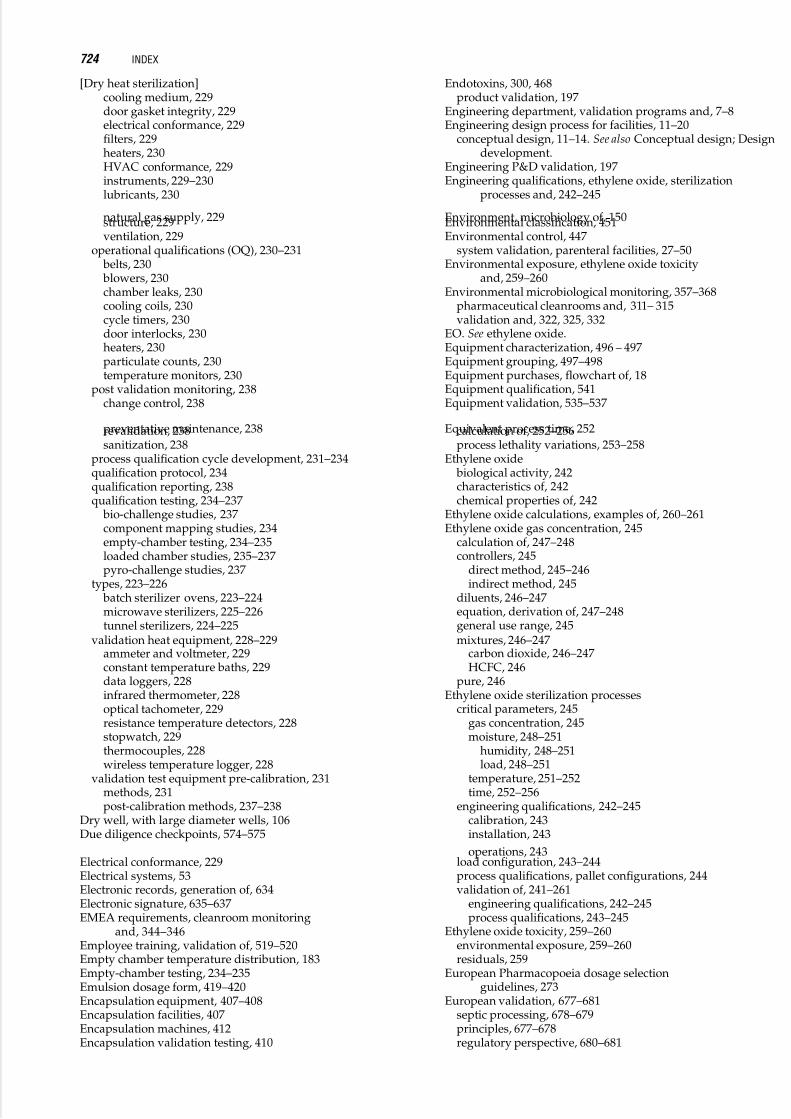
5/17/2018 13243184 Validation Part 8 - slidepdf.com
http://slidepdf.com/reader/full/13243184-validation-part-8 124/143
[Dry heat sterilization]cooling medium, 229door gasket integrity, 229electrical conformance, 229filters, 229heaters, 230HVAC conformance, 229instruments, 229–230lubricants, 230
natural gas supply, 229structure, 229ventilation, 229
operational qualifications (OQ), 230–231 belts, 230 blowers, 230chamber leaks, 230cooling coils, 230cycle timers, 230door interlocks, 230heaters, 230particulate counts, 230temperature monitors, 230
post validation monitoring, 238change control, 238
preventative maintenance, 238revalidation, 238sanitization, 238
process qualification cycle development, 231–234qualification protocol, 234qualification reporting, 238qualification testing, 234–237
bio-challenge studies, 237component mapping studies, 234empty-chamber testing, 234–235loaded chamber studies, 235–237pyro-challenge studies, 237
types, 223–226 batch sterilizer ovens, 223–224microwave sterilizers, 225–226tunnel sterilizers, 224–225
validation heat equipment, 228–229ammeter and voltmeter, 229constant temperature baths, 229data loggers, 228infrared thermometer, 228optical tachometer, 229resistance temperature detectors, 228stopwatch, 229thermocouples, 228wireless temperature logger, 228
validation test equipment pre-calibration, 231methods, 231post-calibration methods, 237–238
Dry well, with large diameter wells, 106Due diligence checkpoints, 574–575
Electrical conformance, 229Electrical systems, 53Electronic records, generation of, 634Electronic signature, 635–637EMEA requirements, cleanroom monitoring
and, 344–346Employee training, validation of, 519–520Empty chamber temperature distribution, 183Empty-chamber testing, 234–235Emulsion dosage form, 419–420Encapsulation equipment, 407–408Encapsulation facilities, 407Encapsulation machines, 412Encapsulation validation testing, 410
Endotoxins, 300, 468product validation, 197
Engineering department, validation programs and, 7–8Engineering design process for facilities, 11–20
conceptual design, 11–14. See also Conceptual design; Designdevelopment.
Engineering P&D validation, 197Engineering qualifications, ethylene oxide, sterilization
processes and, 242–245
Environment, microbiology of, 150Environmental classification, 451Environmental control, 447
system validation, parenteral facilities, 27–50Environmental exposure, ethylene oxide toxicity
and, 259–260Environmental microbiological monitoring, 357–368
pharmaceutical cleanrooms and, 311– 315validation and, 322, 325, 332
EO. See ethylene oxide.Equipment characterization, 496 – 497Equipment grouping, 497–498Equipment purchases, flowchart of, 18Equipment qualification, 541Equipment validation, 535–537
Equivalent process time, 252calculation of, 252–256process lethality variations, 253–258
Ethylene oxide biological activity, 242characteristics of, 242chemical properties of, 242
Ethylene oxide calculations, examples of, 260–261Ethylene oxide gas concentration, 245
calculation of, 247–248controllers, 245
direct method, 245–246indirect method, 245
diluents, 246–247equation, derivation of, 247–248general use range, 245mixtures, 246–247
carbon dioxide, 246–247HCFC, 246
pure, 246Ethylene oxide sterilization processes
critical parameters, 245gas concentration, 245moisture, 248–251
humidity, 248–251load, 248–251
temperature, 251–252time, 252–256
engineering qualifications, 242–245calibration, 243installation, 243
operations, 243load configuration, 243–244process qualifications, pallet configurations, 244validation of, 241–261
engineering qualifications, 242–245process qualifications, 243–245
Ethylene oxide toxicity, 259–260environmental exposure, 259–260residuals, 259
European Pharmacopoeia dosage selectionguidelines, 273
European validation, 677–681septic processing, 678–679principles, 677–678regulatory perspective, 680–681
724 INDEX

5/17/2018 13243184 Validation Part 8 - slidepdf.com
http://slidepdf.com/reader/full/13243184-validation-part-8 125/143
[European validation]steam sterilization, 679–680terminal sterilization, 679–680
Excipients, microbiology of, 140Expansion projects, facility qualification plans, 25Exposure time, chlorine dioxide cycle development
and, 265–266F values, 159–168
background, 159–162
definition of, 159delivered process lethality, 165F0, quantity calculation, 164–165lethal rate, 162–163mathematical F0, 163 – 164Rahn semilogarithmic survivor curve, 165–166
F0, 163–165 d, 164quantity calculation, 164 – 165
Facilities, 446 – 447, 451aseptic processing and, 317–318
validation and, 322, 327–328manual aseptic processes and, 333–334
Facility and equipment qualification plan, in facility design, 19Facility design, construction IQ, 20
detailed design and procurement, 17–20
approach to, 17equipment, 18flowchart of purchases, 18layout, 18planning, 18–19project team, 17
facility and equipment qualification plan, 19qualification
activities during construction phase, 20schedule, 19
site OQ, 20–21validation and, 11–226See also Design development of a facility.
Facility qualification plans, 21–25change control, 24contents of, 21design qualification, 22documentation, 24–25
appendices, 25installation qualification, 22methodology, 21–22operational qualification, 23performance qualification, 23personnel, 23preventive maintenance, 24procedures, 24process validation, 23qualification, 22–23revamp or expansion projects, 25schedule, 23
F bio values, lipid emulsions, 194
FDA guidelines, filter validation study and, 292FDA requirements, cleanroom monitoring and, 343–344Feedstock, 473–474FFS. See form, fill and seal.FH sterilization value, 232
bioburden calculations, 232FH values, examples of, 233Fibers, filter operating study and, 295–296Fill execution, aseptic processing and, 323Filled containers, inspection of, 323–324Fillers, 424Filling lines, speed of, 321Filling
package and, 430positive displacement volumetric system, 430
[Filling]product contact and, 322statistical evaluation, 432–434time-pressure systems, 430–431validation conditions, 431–432weight dosing systems, 431
Filter evaluation, steam sterilization and, 184–185Filter housing configurations, 215–218Filter inertness, 297–300
analytical techniques, 299Fourier transform infrared spectroscopy, 299–300high performance liquid chromatography, 299total oxidizable carbon, 300
chemical compatibility, 299determination techniques, 299gravimetric extractables, 299oxidizable substances, 299pH and conductivity, 299weight change, 299
Filter operating study, fibers, 295–296Filter particle gradation, in pharmaceutical water systems, 83Filter performance reproducibility, 291Filter validation, 287–288
manufacturer’s responsibilities, 290
manufacturing process elements and tools, 290pharmaceutical water systems, 93responsible parties, 289user’s responsibilities, 290
Filter validation studydrug product stability, 300elements of, 289–300
performance reproducibility, 289–291endotoxins, 300filter inertness, 297–300integrity testing, 292
FDA guidelines, 292qualification of, 292
microbial retention, 296–297operating conditions, 293–295
flow rate and throughput, 295pressure, 294–295temperature, 294time, 294
particulates, 295sterilization, 291toxicity, 300
Filters, 207–209, 229, 423–424, 465Filtration sterilization, 151–152Finishing operations, 457Flow rate, 350
filter validation study operating conditions and, 295Flows, 464Foam dosage forms, 419Fogging, 310Foil laminates, 378
Form, fill and seal (FFS) technology, 376–377ready to sterilize, 377ready to use, 377vendor supplied components, 377
Formal regulatory guidelines, 710–712Formulation areas, 359Fourier transform infrared spectroscopy, 299–300Fraction-negative method, 170FT-IR process analyzer, 592Full scale consistency runs, 489Fungistasis test, 662
Gas chromatography, 245–246Gas concentration
chlorine dioxide cycle development and, 265–266
INDEX 725

5/17/2018 13243184 Validation Part 8 - slidepdf.com
http://slidepdf.com/reader/full/13243184-validation-part-8 126/143
[Gas concentration]ethylene oxide, 245
Gas constants, 248Gas decontamination, isolator decontamination and, 279Gas, 451Gases, 52
compressed air, tests for, 55nitrogen, tests for, 56specific tests for, 55–56
[Gases]specific tests for, compressed air, 55specific tests for, nitrogen, 56sterilization, 151
Gassing, 310inert, 321
Gel dosage forms, 420–421Genetic stability, 483–484Genotypic characterization, 483Germicidal action curve, 84Glass, 329, 377
containers, 372–375ampules, 374syringes, 374tubes, 374
vials, 373–374washing of, 372–373siliconization, 373thermal processing, 373
GMPcalibration requirements, 100–101CFR Title 21, 11risk-based approach, 11
Gowningareas, 359–360qualifications, manual aseptic processes and, 334
Gravimetric extractables, 299Grouping, 495Growth promotion, aseptic processing validation, 324Guanidine, 308
Guide to Good Manufaturing Practice Vol. IV, 11
Halogen decontamination process, 284–285HCFC mixture, Ethylene oxide gas concentration and, 246Heat penetration studies, 183–184Heat transfer principles, 226–228
conduction, 227convection, 227radiation, 227
Heat transfer system, 385–386Heaters, 230Hegman Gauge, 424High performance liquid chromatography, 299High-voltage leak detection, 434 – 435Holding times, process chromatography and, 477
Homogenization, 461Homogenizers, 422–423Host cell proteins, 467–468House vacuum systems, 53Humidity
isolator decontamination and, 279measurement of, 248–251
direct method, 250indirect method, 249
HVAC conformance, 229Hydrogen peroxide, 308
decontamination process, 282–283aeration, 284conditioning, 283dehumidification, 283
IAEA dosage selection guidelines, 273Ice-bath reference, thermocouple temperature, 114Identification tests validation, microbiological, 668In Vitro Age, limit of, 486–488Incubation exam, media-filled units and, 324Incubation time, 322
temperature, 322Indirect EO gas measurement, 245Indirect humidity measurement, 249
Industry issues, validation and future of, 715–716Inert gassing, 321Infrared spectroscopy, 299–300Infrared thermometer, 228Infrared, near, 591Inhalers, 375Injectable drugs, launch of validation requirement, 5Inoculation, membrane filters and, 217–218In-process controls
bulk pharmaceutical chemicals and, 448–449vendor qualification and validation, 533–535
In-process media fills, 320–321Inspection
packaging operations and, 438–440automated, 438
presentation devices, 438–439statistical validation, 439–440visual, 438
solid dosage finished goods and, 414Installation qualification (IQ)
dry heat sterilization and, 229ethylene oxide sterilization processes and, 243of a facility, 22of critical utilities, 54
Instrument conformance, 229–230Integrated control functions, lyophilization
validation and, 389Integrity
container closure, 435–436filter validation and, 292
Interventions, aseptic processing and, 323Investigations, cleanrooms and contamination of, 315Ion exchange
pharmaceutical water systems, 86–87validation, in pharmaceutical water systems, 90–91
Ionizing radiation sterilization, 151IQ. See installation qualification.IQ. See irradiator commissioning.Irradiator commissioning (IQ), 270–271Isoform distribution, 488–489Isokinetic sampling, 352Isolate identification, 313–314Isolated high values, 312Isolation, 457
technology, 451Isolator decontamination, 277–285
essential requirements, 279–282aeration, 281–282agent concentration, 279
biological indicators, 280cycle development, 280–281humidity, 279intervals, 281materials issues, 281residuals, 281revalidation frequency, 281temperature, 279–280uniformity of conditions, 280
methods, 282–285halogens, 284–285hydrogen peroxide decontamination, 282–283
726 INDEX

5/17/2018 13243184 Validation Part 8 - slidepdf.com
http://slidepdf.com/reader/full/13243184-validation-part-8 127/143
[Isolator decontamination]peracetic acid, 285
process objectives, 278–279gas decontamination, 279product contact material sterilization, 278–279wrapped sterile materials, 279
Isolator systemsdesign of, 400environmental concerns, 400
equipment qualifications, 400–401fabrication of, 400installation, 400maintenance, 401use of, 401validation concerns, 156, 399–402
Isolator technology, 326
Jacket services, 448 Japanese regulatory requirements, 683–694
approval reviews, 684–684historical background, 685–686licensing, 684Pharmaceutical Affairs Law, 683–694usage approval, 684
validation, 686–687 Japanese validation methods, 687–694aseptic processing, 687–692
bioburden cycle, 693–694environmental monitoring, 690facility design, 687–689overkill method, 693–694simulations, 691–692steam quality, 693steam sterilization, 692terminal processing, 692water systems, 689–690
Kettles, 421Knowledge management tools, 592–593
Laboratory information management system (LIMS) business process, 630–632combined risk assessment, 637current process understanding, 630description of, 639documentation, 638–639electronic process
benefits, 631– 632optimization, 630–631
electronic record generation, 634end-user testing, 639environment design of, 632–634implementation of, 634–639life cycle implementation, 634–635
personnel training, 638–639risk-based validation, 634–640 (LIMS)server installation, 637–638
change control, 637–638configuration management, 637–638system architecture, 637traceability matrix, 637
user requirement specifications, 635–637software release notes, 635defining system requirements, 635prototyping, 635electronic signature, 635, 637
validation plan creation, 637validation summary report, 639–640validation, 641–651
[Laboratory information management system (LIMS)]CFR 21 Part 11, 651configuration control, 650data archive, 650design qualification, 648disaster recovery, 650–651full vs. incremental, 650function and design, 647–648installation qualification, 648
meta data, 650operational qualification, 648–649performance qualification, 649planning, 646–647project planning, 642–651requirements definition, 644–646risk management, 646system complexity, 644system definition, 643trace matrix, 649
LAL test, 233–234Large volume parenterals (LVP) validation, 2Laws, validation and, 709Layout, 451
in design of a facility, 12–13
Lean methods, resistance to, 566Lethal rate, F values and, 162–163Letters to the industry, 713Licensing, Japanese regulatory requirements and, 684Life cycle model, 444Light-induced fluorescence, 592Limit of In Vitro Age, 486–488LIMS. See Laboratory information management system.Lipid emulsions, accumulated F bio values and, 194Liquid chromatography, 299Liquid dosage forms, 418–419Liquid-liquid extraction, 462Liquids, 52–53
manufacturing equipment, 421–424purified water, specific tests for, 56specific tests for, 56water for injection, specific tests for, 56water pretreatment, specific tests for, 56
Load configuration, ethylene oxide sterilization processesand, 243–244
Load moisturization, 248–251external preconditioning, 250
Load moisturization in sterilizer, 250DEC cycle, 250–251RH monitoring, 251SAC cycle, 250
Loaded-chamber studies, 235–237Loop method, 216Lotion dosage forms, 420Lot-to-lot cleaning, 449–450Low traffic flow layout, 15
Lubricants, 230LVP (large volume parenterals) validation, 2Lyophilization validation of, 381–396
assay, 396available information, 382
bulk solution stability, 392development activities, 390drug substance, 390–391equipment performance tests, 385–389
condenser, 386control functions, 386heat transfer system, 385–386integrated control functions, 389pressure control, 387process
INDEX 727

5/17/2018 13243184 Validation Part 8 - slidepdf.com
http://slidepdf.com/reader/full/13243184-validation-part-8 128/143
[Lyophilization validation of]monitoring, 387testing, 387–388
sequencing functions, 387shelf temperature control, 386–387sublimation/condensation rate tests, 387uniformity, 388–389vacuum system, 386
finished product attributes, 394–396
physical appearances, 394reconstititution, 396residual
moisture, 395–396solvents, 396
finished product formulation, 391preformulation data, 389–390preparatory steps, 381processing parameter justification, 392–393protocol preparation, 382–385
acceptance criteria, 383equipment qualification, 383–384installation qualification, 384operational qualification, 385
scope and objectives, 385
thermal characteristics, 391
Machine surface site selection, 359Maintenance department, validation programs and, 8Maintenance of validation, steam sterilization and, 185Manifold monitoring, cleanroom and, 347Manual aseptic processes
components, 334containers, 334design principles of, 334– 335equipment, 334facility concerns, 333–334handling challenges, 334personnel
gowning qualification, 334training, 334
time limitations, 334validation of, 333–337
Manual components, 464Manual filling, 321Manufacturing equipment, liquids and semisolids, 421–424
centrifuges, 423combination equipment, 423dispersers, 422–423fillers, 423filters, 423homogenizers, 422–423kettles, 421mixers, 422pumps, 423tanks, 421
Manufacturing, aseptic processing validation and, 322–323Master solution/product concept, sterilization cycle and, 194Material specifications, 448Mathematical F0, 163–164Mathematical modeling, steam sterilization and, 176–177Media considerations, viable environmental microbiological
monitoring and, 363Media fill volume, 321Media fills, in-process, 320–321Media life span, 477– 478Media run duration, 320Media run frequency, 320Media selection, 321Media sterilization, 319–320
aseptic filling and, 325
Media-filled units, post-incubation examination of, 324Membrane filters, 215–218
autoclaves, 218housing configuration, 215–218inoculation and testing, 217–218loop method, 216sterilization of, 216 – 217
Meta data, 650Method validation, 509
Metrology, 99–107Microbial closureinactivation validation, 194, 196validation, 198
Microbial contamination, 661sources and vectors, 311–312
Microbial growth, 661–662Microbial identification, aseptic processing validation, 324Microbial inactivation, kinetics of, 169Microbial identification, 366Microbial lethality requirementsD and Z values, 232depyrogenation-pyroburden calculations, 232–233FH sterilization value, 232FH values, 233
LAL test, 233–234Microbial recovery, 661–662Microbial retention, filter validation study and, 296–297Microbial solution validation, 197–198Microbiological challenges, steam sterilization and, 184Microbiological identification method validation, 668Microbiological method validation, 665–670
qualitative, 665–666quantitative, 666–668USP tests, 668–669
Microbiological monitoring, 357–368aseptic processing and, 325–326
Microbiological test method validation, 661assay variability control, 661–662
contamination, 661growth, 661– 662recovery, 662
bioburden, 662 – 663sterility test, 662test limits, 662
Microbiological validation, of pharmaceutical water systems, 73Microbiology of drug substances, 149Microbiology
introduction to, 147–156of bacterial endotoxins, 150of biologic substances, 149of environment, 150of excipients, 149of raw materials, 149of water, 149–150sterility testing and assureance, 150
Microfiltration, 460Microorganism resistance, sterilization and, 159Microorganisms
in pharmaceutical process, 148 – 150pharmaceutical water systems, pretreatment, 79–82
Microprocessors, 623Microwave sterilizers, 225–226Mixers, 422Moisture conditioning, chlorine dioxide cycle development and, 265Moisture, ethylene oxide sterilization process and, 248–251
humidity, 248–251load, 248–251
Monitoring, 514–515Multicomponent analysis tools, 586–590Multimedia deep beds, in pharmaceutical water systems, 85
728 INDEX

5/17/2018 13243184 Validation Part 8 - slidepdf.com
http://slidepdf.com/reader/full/13243184-validation-part-8 129/143
Multinational company validation, 695–702countermeasures, 701–702developmental history, 696–697execution of, 700–701master plan, 696–697process
flow documents, 697– 698validation, 699–700
qualification, 698–699
technical evaluations, 701technology transfer, 698
Multiple crops, 448Multi-point temperature measurement, steam SIP and, 215Multivariate tools, 586
Nanofiltration, 460Nasal products, 545–546Natural gas supply, 229Natural waters, in pharmaceutical water systems, 76Near infrared, 591Networks, 624– 625New product validation, 549–553
protocol development phase, 549–550required, 549
summary report, 552test functions, 550
Nitrogen, specific tests for, 56Noncompendial method, 662–663Nonsterile products
aerosol cans, 378 blister packaging, 378caps, 378container preparation processes validation and, 377delivery systems, 378foil laminates, 378glass, 377origins of validation for, 2plastics, 377
Nonviable particle environmental monitoring, 339–355
aerosols, 351–355aseptic processing and, 326automated, 347cleanroom
certification, 341–342monitoring, 342–346
optical particle counters, 347–351portable testing, 346–347rationale for, 339–341
fundamentals, 339proof of control, 339–341regulatory standards, 341
Nucleic acids, 467
Object mapping, steam sterilization validation process and, 183
Open systems, aseptic processing validation and, 328Operational qualification (OQ)
dry heat sterilization and, 230–231ethylene oxide sterilization processes and, 243of a facility, 23
of critical systems, 54 – 55radiation sterilization and, 271verification, 464 – 465
alarms, 465check automated components, 464check manual components, 464computer control, 465detectors/recorders, 464 – 465filters, 465flows/pressures, 464
[Operational qualification (OQ)]system integrity, 464training, 464
Optical particle counters (OPC), 347–351calibration of, 349error control, 349–351
counting efficiency, 350particle concentration capability, 350–351sample flow rate, 350
sensor resolution, 350signal-to-noise ratio, 349–350sizing accuracy, 350
operation of, 348–349Optical tachometer, 229OQ. See operational qualification.Oral liquids
history of, 417–418process validation protocol, 425 – 426validation, 417–426
life cycle, 426test equipment, 424
Organic carbons, in pharmaceutical water systems, 81–82Organic compound measurement, in pharmaceutical water
systems, 75
Organism resistance data, 84Organizational transfers, 9Organizing for validation, 5–10
consulting firms, 6–7continuing education, 9contract manufacturers, 8–9department interactions, 7FDA/EMEA as regulator, 8mission formulation, 5organizational transfer, 9product lines, 6professional associations, 8size of organization, 6staffing a validation group, 6–7
diversity in, 6
skills requirements, 6–7validation technician, 6–7
Osmosis, reverse, in pharmaceutical water systems, 87–88Ostomy adhesives, 421Overkill
cycles, 180method, 693–694
Oxidizablecarbon, 300substances, filter inertness and, 299
Oxygen removal, packaging and, 436–438Ozone validation, in pharmaceutical water systems, 92Ozone, in pharmaceutical water systems, 84
Packaging operations
container closure integrity, 435–436container sealing, 434 – 436filling, 430high-voltage leak detection, 434 – 435inspection, 438 – 440oxygen removal, 436 – 438pressure differential, 435product shelf life, 435–436secondary, 440–442validation, 429–442
Packaging, solid dosage finished goods and, 414Pallet configurations, ethylene oxide sterilization processes
and, 244Parametric product release, dry heat sterilization and, 258Parametric release of sterilized products, 153
INDEX 729

5/17/2018 13243184 Validation Part 8 - slidepdf.com
http://slidepdf.com/reader/full/13243184-validation-part-8 130/143
Parenteral facilities, environmental control system validationand, 27–50
Parenteral product sterilization, 187Part 11, CFR, 626–627, 651Particle concentration capability, 350–351Particle loss, transport tubing and, 352–353Particle migration, 351–352Particle monitoring, 314Particle sizing accuracy, 350
Particulate contaminants, 339–340Particulate counts, 230Particulates, filter operating study and, 295Passive air
monitoring, 314testing methods, 360
Paste dosage forms, 420PAT. See process analytical technology.PDA dosage selection guidelines, 273Peracetic acid decontamination, 285Performance qualification, 465–466
cleaning validation, 465coupon testing, 466life span, 466of a facility, 23
of critical systems, 55rinse studies, 465sterilization, 466swab studies, 465–466See also process qualifications.
Performance reproducibilitydrug product, 289–291filter validation study and, 289–291
Peroxides, 308Personal computers, 624Personnel monitoring, aseptic processing and, 318Personnel qualification, aseptic processing, 318Personnel,
bulk pharmaceutical chemicals (BPC)recordkeeping and, 450
in facility qualification plans, 23manual aseptic processes and, 334surface disinfection and, 311training of,
aseptic processing and, 318 bulk pharmaceutical chemicals and, 329
pHfilter inertness and, 299measurement, in pharmaceutical water systems, 75meters, 424
Pharmaceutical Affairs Law, 683–694Pharmaceutical cleanrooms
cleaning and disinfecting of, 303–315environmental monitoring results, 311–315
active air, 314aseptic critical processing zones, 314–315
investigations, 315isolated high values, 312–313isolate identification, 313–314microbial contamination, 311–312particles, 314passive air monitoring, 314surface, 314trends, 313
environmental monitoring,Pharmaceutical Inspection Cooperation Scheme, 346Pharmaceutical radiation sterilization, validation of, 269–274Pharmaceutical water systems
alert and action levels, 74–75carbon beds validation, 90cleaning and sanitization, 76
[Pharmaceutical water systems]conductivity measurement, 75deep bed filter validation, 89definition of validation, 61design
considerations, 82–88documentation, 66
distillation, 88validation, 91–92
documentation, 61–63as GMP requirement, 61–62contents of, 61goals of, 62–63
experimentation and water systems,filter validation, 93
GMPs, 88information master file, 61ion exchange, 86–87
validation, 90–91ionic constituents in, 82microbiological
assay methods, 74levels, 73–74validation, 73
microorganisms, 82organic carbons, 81–82organic compound measurement, 75ozone validation, 92pH measurement, 75pretreatment, 79–82
reasons for, 79–80principal purification unit processes, 86purification unit, 82–86recovery, 88reverse osmosis (RO), 87–88
validation, 90sampling program, 76–78scale-forming elements, 81site specificity, 78softening operations validation, 89–90source water analyses, 78–79specific impurities, 80–81specific unit process validations, 88–93
chlorination unit, 89surface water, 79suspended solids, 80–81testing for specific organisms, 74ultraviolet validation, 92–93USP standards, 75Validation, 59–97
background, 59–60document example, 62–63exercise, 72–76plan, 67sequence, 64–72
change control, 70–72controls, 69equipment design, 64–67final reports, 72installation qualification, 67–69instruments, 69operational qualification, 69–70performance qualification, 70
steps, 63–64submittal documents, 66
timeline, 71water constituents, 76–79
natural waters, 76regional differences in, 76–77
well water, 79
730 INDEX

5/17/2018 13243184 Validation Part 8 - slidepdf.com
http://slidepdf.com/reader/full/13243184-validation-part-8 131/143
Phenols, 308Physical methods validation, 655–663Physical parameters, 446Physicochemical indicators of sterilization, 153Physicochemical validation, case studies, 657–658Piping systems, 206–207, 208Placebos, aseptic filling and, 325Plant steam, 53Plasma, 545
Plastics, 377 bags, 329containers, sterilization of, 376
PLC. See programmable logic controllers.Polishing, 414Portable testing of cleanroom, 346–347Post-sterilization integrity, steam SIP and, 204–205PQ, radiation sterilization and, 271Precipitation, 462Precondition, chlorine dioxide and, 263Preparations area, 328Pre-requisites for validation, 2Presentation devices, 438 – 439Pressure control, 387Pressure differential, 435
Pressure vessels, 205–206Pressure, filter validation study operatingconditions and, 294 – 295
Preventative maintenancedry heat sterilization and, 238in facility qualification, 24
Primary dosimetry, 270Printing, solid dosage finished goods and, 414Procedures
bulk pharmaceutical chemicals (BPC)recordkeeping and, 450
in facility qualification plans, 24steam SIP and, 204
Process analytical technology (PAT) validation, 583–601analytical method, 594
benefits of, 585calibration, 598–599challenges, 600computerized system 597–598equipment qualification, 598guidance, 586principles, 586–593process, 598requirements, 593–600revalidation, 599summary,599tools, 586–593
knowledge management, 592–593multicomponent analysis, 586–590multivariate, 586process analyzers, 591
process control, 592Process analytical technology validation, conventional
manufacturing paradigm, 583–585Process analyzers, 591
CCD camera, 592FT-IR, 592light-induced fluorescence, 592near infrared, 591Raman Spectroscopy, 591–592X-ray diffraction, 592
Process characterization, 459Process chromatography validation, 473–480
cleaning and sanitization, 478developmental program, 473–475
characterization, 474
[Process chromatography validation]feedstock, 473–474quality goals, 474quantity goals, 474
holding, processing and storage times, 477media life span, 477–478production, 476–477small scale, 475–476
Process control
chlorine dioxide and, 267–268radiation sterilization and, 274tools, 592
Process development studieschlorine dioxide cycle development and, 266contract manufacturing validation and, 571–572
Process equipment qualification, 462–466operational verification, 464–465performance, 465–466
Process flow documents, 697–698Process gases, 447Process lethality variations, 253–258Process monitoring, 387Process parameter, 489Process qualification cycle development
dry heat sterilization and, 231–234operating parameters, 231–234microbial lethality requirements, 231–345
Process qualifications, ethylene oxide sterilization processesand, 243–245
Process related components, 469–470Process scaling, recovery and purification process steps
and, 458–459Process simulations, aseptic processing validation and, 330–331Process testing, 387–388
terminal sterilization and, 198–199Process validation, 541–542, 598, 699–700
of a facility, 23protocol
oral liquid, 425–426semisolid, 425–426topical liquids, 425–426
recovery and purification process steps and, 457–458report, 426
Process water, 447Processing times, process chromatography and, 477Product contact
during filling, 322material sterilization, isolator decontamination
and, 278–279Product grouping, 497–498Product release, dry heat sterilization and, 256–258Product shelf life, 435–436Product sterilization, 450Production department, validation programs and, 8Production process chromatography validation, 476–477
Professional associations, importance of, 8Programmable logic controllers (PLC), 623–624Proof of control
cleanroom activities, 341particulate contaminants, 339–340viable contaminants, 340–341
Proposed regulations, 712–713Protein modification, 456Protocol
development, 511–512lyophilization validation and, 382–385refinement and execution, 512–514
PSLR values, 194Pulsing cycle, 180Pumps, 423
INDEX 731

5/17/2018 13243184 Validation Part 8 - slidepdf.com
http://slidepdf.com/reader/full/13243184-validation-part-8 132/143
Purerooms, 447steam, 53
Purge cycle, 191Purification unit, in pharmaceutical water systems, 82–86
carbon bed operation, 85–86chloramination, 83chlorination, 83multimedia deep beds, 85
ozone, 84ultraviolet radiation, 84water softener, 86
Purified water, specific tests for, 56Purity
chemical, 446profiles, 448 – 449
Pycnometer, 424Pyro-challenge studies, 237
QAC. See quaternary ammonium compounds.Qualification activities, facility construction phase, 20Qualification lots, 459Qualification of change control, 129–145Qualification
facility, 22–23of design of a facility, 13–14validation vs., 129
Qualitative microbiological method, 665–666Quality assurance department, validation programs and, 8Quality control department, validation programs and, 8Quantitative microbiological method validation, 666–668Quaternary ammonium compounds (QAC), 307–308
R&D department, validation programs and, 7Radiation, 227, 452Radiation sterilization
components of, 270dosage selection guidelines, 272–274
AAMI/ANSI/ISO Standard, 272–273
British Pharmacopoeia, 273European Pharmacopoeia, 273IAEA, 273–274PDA, 273USP procedure, 272
dosimetry, 270–271irradiator commissioning (IQ), 270–271legal considerations, 274OQ, 271pharmaceuticals, validation of, 269–274PQ, 271process control, 274
Rahn semilogarithmic survivor curve, 165–166Raman, spectroscopy, 591–592Raw materials, microbiology of, 149
Recirculated superheated watercycle, 191–192sterilization, 188
Reconstitution, 396Recorders, 464 – 465Recovery and purification process steps, 456 – 457
biomass removal, 456cell disruption, 456cell harvesting, 456clearance studies, 466finishing operations, 457isolation, 457process equipment qualification, 462 – 466process scaling, 458– 459
characterization, 459
[Recovery and purification process steps]qualification lots, 459scale-down, 458– 459scale-up, 458
process validation, 457– 458critical quality attributes, 457
protein modification, 456purification, 457unit operations, 459– 462
Recovery and purification processes,validation, 455– 470viral inactivation, 457
Recovery, in pharmaceutical water systems, 88Redress validation, 412–413Reference dosimetry, 270Reference errors, using thermocouples, 105Refractometers, 424Regional differences, in pharmaceutical water
systems, 76–77Regulations re validation, 444, 709Regulatory considerations, contract manufacturing validation
and, 575–582Regulatory standards, nonviable particle environmental
monitoring and, 341
Regulatory validation aspects, 709–714laws, 709Regulatory validation guidelines, 709–714
formal, 710–712letters to the industry, 713other documents, 713–714proposed, 712–713
Release criteria, 533–535Reproducibility of performance, 289–291Residual agents, isolator decontamination and, 281
ethylene oxide toxicity and, 259Residual moisture, 395–396Residual sampling, 450Residual solvents, 396Residue identification, 495–496Residues, disinfectants and, 311Resistance of microorganisms, sterilization and, 159Resistance temperature
detectors, 228measure circuit, four-wire, 125
Resistance, disinfecting agents and, 306–307Resolution, temperature measurement errors, 120Retrospective validation, 555–564
API, 555–557drug product, 558foundation for, 555planning, 557–558
Revalidation, 495, 599dry heat sterilization, 238frequency, isolator decontamination and, 281
Revamp projects, facility qualification plans, 25
Reverse osmosis (RO), in pharmaceutical water systems, 87–88Rework validation, 412 – 413RH monitoring, 251Rinse studies, 465Risk based
approach, 406validation, 634–640
Risk management, 520, 646Risk
surface cleaning and, 305–306surface disinfection and, 311
RO (reverse osmosis) validation, in pharmaceutical watersystems, 90
Rotary sterilization, 188Routine dosimetry, 270–271
732 INDEX

5/17/2018 13243184 Validation Part 8 - slidepdf.com
http://slidepdf.com/reader/full/13243184-validation-part-8 133/143
SAC cycle, 250Safety, 447
factors, chlorine dioxide and, 267Sample point, aerosol particle monitoring and, 353–355Sampling program, in pharmaceutical water systems, 76–78Sampling techniques, campaign production and, 501–504Sanitization, 238
validation, 478–479Saturated steam
gravity displacement, 191pre-vacuum cycle, 191
SCADA. See supervisory control and data acquisition.Scale-down, 458 – 459Scale-forming elements, in pharmaceutical water systems, 81Scales, 424 – 425Scale-up, 458Schedule, for facility qualification, 23Scripting language, 638Secondary packaging operations, 440–442Seebeck coefficients of common thermocouple
materials, 113pairs, 113
Semisolidshistory of, 417–418
manufacturing equipment, 421–424process validation protocol, 425–426validation, 417–426
life cycle and, 426test equipment, 424
Sensor and circuit errors, temperature measurements, 117Sensor design, for temperature measurements, 126–127Sensor resolution, 350Separated flow
in and out layout, 15with garment reuse layout, 15
Sequencing functions, 387Server installation, laboratory information management system
and, 637–638Shaker sterilization, 188Shelf life, 435–436
product testing, 199Shelf temperature control, 386–387Shipping, solid dosage finished good validation and, 414Short duration deviations, 489Signal-to-noise ratio, 349–350Siliconization, 373Simulations, aseptic processing and, 691–692SIP. See sterilization in place.Site OQ (operational qualification), 20–21Site specificity, in pharmaceutical water systems, 78Six Sigma
definition of, 565–566harnessing of, 567–568lean methods, 566obstacles, 566–567
resistance to, 566step vs. process, 567validation, 565–570
Skin disinfectants, 308Small company validation, 703–708
documentation, 707implementation, 707–708management team, 706planning, 704
Small scale process chromatography validation, 475–476Softening operations in pharmaceutical water
systems, 89–90Software coding, 615–616Software maintenance, 617Software release notes, 635
Software revisions, 617Software testing, 616Software validation, 611–613
defect prevention, 612life cycle, 612–613post change review, 613requirements, 612time and effort investment, 612
Solid dosage finished goods
coated tablet cores, 413coatings, 413compressing validation testing, 410dosage forming step, 403–404encapsulation validation testing, 410inspection, 414packaging, 414polishing, 414printing, 414shipping validation, 414validation, 403–414validation acceptance criteria
blend, 410capsule, 410tablet, 410
validation concerns, 405–413accessory equipment, 412 bio-batch equivalence, 411 blend sampling, 409–410 bulk in-process storage, 411–412compressing and encapsulation facilities, 407compressing equipment, 407–408critical attributes, 406–407data evaluation, 413development data, 411encapsulation
equipment, 407–408machines, 412
installation qualifications, 408operational qualification, 408performance qualification, 408prerequisites, 405–406raw materials, 411rework/redress, 412–413risk based approach, 406sampling plans, 408–409specifications, 407standard operating procedures, 410–411
validation documentation, 404–405validation nomenclature, 404–405
Solid dose discussion, 541–542equipment qualification, 541process validation, 541–542
Solution/product moist heat resistanceD-value analysis, 193–194z-value analysis, 193–194
Solvent distribution, 448Solvent recovery and reuse, 448Source water analyses 80
in pharmaceutical water systems, 78–79Spearman-Karber method, 170–171Specific tests
gases, 55–56liquids, 56steam, 56vacuum systems, 57water, 56
Spectroscopy, 299–300Spore cultivation, 168
types available, 168–169Stability, chlorine dioxide gas, 267
INDEX 733

5/17/2018 13243184 Validation Part 8 - slidepdf.com
http://slidepdf.com/reader/full/13243184-validation-part-8 134/143
Staffing issues, in organizing a validation group, 6–7consulting firms, 6–7continuing education,department interactions, 7diversity in, 6–7organizational transfers, 9skills requirements, 6–7validation technician, 6–7
Stainless steel, 329
Statistical validation, package inspectionand, 439–440Steam purge cycle, 191Steam quality, 693Steam sterilization in place, 201–221
air removal, 203automation, 220
bulk sterilization, 220–221condensate removal, 204filters, 207–209fundamentals of, 202–203membrane filters, 215–218multi-point temperature measurement, 215piping systems, pros and cons, 208post-sterilization integrity, 204–205
procedural conformance, 204procedures, 212–214process control, 214–215process of, 209–212saturated steam, 201–202system design, 205
piping system, 206–207, 208pressure vessels, 205–206
uses of, 221validation, 218–220
cycle development, 218–219installation, 218performance qualification, 219–220
Steam, 53, 451diffusion of, 119–120specific tests for, 56types of, 53
Steam-air mixturecycle, 191sterilization, 188
Steam sterilization, 151, 679–680, 692assurance development, 180autcoclaves, 175–186BI, 692–693characteristics of, 179control systems, 179–180cycles, 180, 190–192
overkill, 180purge, 191recirculating superheated water, 191–192saturated steam-gravity displacement, 191
saturated steam-pre-vacuum, 191steam-air mixture, 191
design of, 178–179mathematical modeling, 176–177mechanism of, 176–186process confirmation, 180–185thermal death time curve, 177–178vacuum creation, 180
pulsing cycle, 180validation process, 180–185
container and object mapping, 183empty chamber temperature distribution, 183equipment qualification, 182–183filter evaluation, 184–185heat penetration studies, 183–184
[Steam sterilization]maintenance, 185measuring temperature, 181–182microbiological challenges, 184report, 185
Steam sterilization in place (SIP), 201–221Steel, stainless, 329Stem conduction calibration error, 106Sterile bulk pharmaceutical chemicals (BPC),
validation of, 450–452closed systems, 450–451environmental classification, 451facilities, 451isolation technology, 451layout, 451product sterilization and sterility assurance, 450sterilization in place, 451utility systems, 451
Sterile clinical trial material drugs, 543–544validation requirements, 544–545
Sterilematerials, isolator decontamination and, 279powders, 322–323products, 372–376
closures, 374–375glass containers, 372- 375Sterility
assurance, 450laboratory, monitoring of, 367–368product samples, 329testing, 199, 332
assurance of, 150 bacteriostasis/fungistasis test, 662
Sterilization cycle development, 192–197accumulated F bio values, 194activity, 192container
closure integrity validation, 196–197thermal mapping studies, 192–193
endotoxin product validation, 197master solution/product concept, 194microbial closure inactivation validation, 194, 196PSLR values, 194solution/product moist heat resistance analysis, 193–194
Sterilization in place (SIP), 451chemical, 452dry heat, 451–452gas, 451radiation, 452steam, 451
Sterilization process factors, 159microorganisms resistance, 159temperature, 159–166time, 159–166
Sterilization processes, 144–156
aseptic processing, 152container/closure integrity validation, 154dry heat sterilization, 151filtration sterilization, 151–152gases sterilization, 151ionizing radiation sterilization, 151parametric release, 153steam sterilization, 151validation of, 152–156
aseptic processes, 155 biologic indicators, 152physicochemical indicators, 153
Sterilization production facility development, 197–198engineering P&D validation, 197microbial
734 INDEX

5/17/2018 13243184 Validation Part 8 - slidepdf.com
http://slidepdf.com/reader/full/13243184-validation-part-8 135/143
[Sterilization production facility development]closure validation, 198solution validation, 197–198
Sterilization, 466aseptic processing validation and, 331–332
bulk, 220–221chlorine dioxide, 263dry heat, 223–240F values, 159–166
[Sterilization]media, 319–320membrane filters and, 216–217plastic containers and, 376steam, 175–186steam, 679–680terminal, 187–199, 679–680
Sterilizer control systems, 189–190Sterilizing-grade filters, validation of, 287–301Stirred-tank reactions, 461–462Stoppers, 374–375
washing of, 374–375Stopwatch, 229Storage times, process chromatography and, 477Structural conformance, 229
Stumbo-Murphy-Cochran method, 171–172Sublimation rate tests, 387Summary report, 552Supervisory control and data acquisition (SCADA), 625–626Supply validation, 537–539Supportive clean area, 318
dissolution area, 328preparations area, 328aseptic processing validation and, 328
Suppository dosage forms, 421Surface cleaning
cleanrooms and, 304–306equipment and, 305risk considerations of, 305–306
Surface disinfectants, 309
continued use of, 310–311effectiveness validation, 310qualification, 310
gassing and fogging, 310risk considerations, 311
residues, 311type used, 311unskilled personnel, 311
Surface monitoring, 314, 358Surface testing methods, 362–363Surface water, in pharmaceutical water systems, 79Survivor curve method, 170Suspended solids, in pharmaceutical water systems, 80–81Suspension dosage forms, 419 – 420Suspensions, 322Swab studies, 465–466Syringes, 374System architecture, 637System calibration measurement, in temperature
measurements, 122System integrity, 464System qualification matrix, 24
Tablet validation acceptance, 410Tanks, 421Technical considerations, contract manufacturing validation
and, 575–582Technology transfer, 698Temperature change, z value, 172Temperature distribution, empty chamber, 183
Temperature measurements, 109–127calibration procedures, 121–124errors, 116–121
circuit resistance, 120conformity to standard, 117, 120diffusion of steam, 119–120measuring system errors, 120repeatability, 120–121resolution, 120
sensor and circuit errors, 117uniformity, 120resistance temperature detectors, 124–125
Wheatstone bridge, 125sensor design, 126 – 127system calibration measurement, 122
Temperature monitors, 230Temperature sensors, 104Temperature transfer standard, 105Temperature
ethylene oxide sterilization processes and, 251–252filter validation study operating conditions
and, 294incubation time and, 322isolator decontamination and, 279–280
sterilization and, 159–166Terminal processing, aseptic processing and, 692Terminal sterilization, 679–680Terminal sterilization validation, 187–199
continuous, 188–189control systems, 189cycle development, 192–197cycles of, 190–192design considerations, 187–188parenteral product, 187process testing, 198–199
antimicrobial preservative efficacy, 199 bioburden analysis, 198–199shelf-life, 199sterility testing, 199
production facility development, 197–198recirculated superheated water, 188rotary and shaker, 188steam-air mixture, 188
Test media selection, 321Test method validation, 655Testing frequency, viable environmental microbiological
monitoring and, 358–359Thermal death time curve, 177–178Thermal processing, 373Thermocouple calibration measurement, 122–124Thermocouple circuit
simple, 112typical, 112–113
duplex-lead, 113with compensator, 115
with ideal reference, 114with internal thermocouples, 115with two sections, 119
Thermocouple compensators, 114–115Thermocouple materials, Seebeck coefficients, 113Thermocouple reference temperature, 114–116
automatic references, 114ice-bath reference, 114multichannel systems, 115–116thermocouple compensators, 114–115
Thermocouple system withcomputer and external UTR, 117computer and internal reference, 116internal compensator, 116
Thermocouple with connector, 118
INDEX 735

5/17/2018 13243184 Validation Part 8 - slidepdf.com
http://slidepdf.com/reader/full/13243184-validation-part-8 136/143
Thermocouple, 109, 228 basic, 110reference errors and, 105
Thermoelectric theory, 109–114Thermometry, 425Throughput, filter validation study operating conditions
and, 295Time limitations, 330, 334
aseptic processing and, 319
Time of testing, viable environmental microbiologicalmonitoring and, 360
TimeD value, 166–172equivalent process, 252ethylene oxide sterilization process and, 252–256filter validation study operating conditions and, 294sterilization and, 159
Time-pressure systems, 430–431Tools
knowledge management, 592–593multicomponent analysis, 586–590multivariate, 586process control, 592
Topical liquids
history of, 417–418validation life cycle and, 417–426test equipment, 424
Topical lotion dosage forms, 420Total oxidizable carbon, 300Toxicity, 300
ethylene oxide, 259–260TQM philosophies, 5–6Trace matrix, 649Traceability matrix, 637Traffic patterns, viable environmental microbiological
monitoring and, 359Training, 464
validation, 519–528 benefits of, 519
evaluation preparation, 521–525execution of, 520–521new employee training, 519–520program documentation, 520regulations, 519risk management, 520
Transdermal adhesives, 421Transfer calibration error, 105Transfer dosimetry, 270Transport tubing particle loss, 352–353Tubes, 374Tunnel sterilizers, 224–225
Ultrafiltration, 460Ultraviolet radiation, in pharmaceutical water systems, 84
Ultraviolet validation, in pharmaceutical water systems, 92–93Uniformity of conditions, isolator decontamination and, 280Uniformity within lyophilization, 388–389Unit operations, 445– 446, 459 – 462
centrifugation, 459–460depth filtration, 461diafiltration, 460homogenization, 461liquid-liquid extraction, 462microfiltration, 460nanofiltration, 460precipitation, 462stirred-tank reactions, 461–462ultrafiltration, 460
United States, validation implementation in, 671–675
Unskilled personnel, surface disinfection and, 311User requirement specifications, laboratory information
management system and, 635–637defining system requirements, 635electronic signature, 635–637prototyping, 635software release notes, 635
USP dose selection guidelines, 272USP microbiological test validation, 668–669
USP standards, pharmaceutical water systems, 75Utility systems, 451
Vacuum creation, steam sterilization and, 180pulsing cycle, 180
Vacuum system, 386specific tests for, 57
Validation conditions, filling and, 431–432Validation document matrix, 17Validation heat equipment, 228–229
ammeter and voltmeter, 229constant temperature baths, 229data loggers, 228infrared thermometer, 228optical tachometer, 229
resistance temperature detectors, 228thermocouples, 228wireless temperature logger, 228
Validation implementation in United States, currenthistory, 671–675
Validation in Europe, 677–681Validation life cycle, oral liquids and, 426Validation master plan, facility and equipment, 14Validation of lyophilization, 381–396Validation of terminal sterilization, 187–199Validation organizations, early, 5Validation process, steam sterilization and, 182–183Validation programs
contract manufacturers and, 8–9engineering department and, 7–8maintenance department and, 8production department and, 8quality assurance department and, 8quality control department and, 8R&D department and, 7
Validation regulatory aspects, 709–714Validation report, 185Validation requirements, 544–545
biologicals, 545 blood products, 545nasal products, 545–546plasma, 545
Validation summary report, 639–640Validation technician, importance of, 6Validation test equipment
balances, pycnometers, scales, 424–425
Hegman Gauge, 424oral/topical liquids, 424pH meters, 424pre-calibration, dry heat sterilization and, 231refractometers, 424thermometry, 425viscometers, 424
Validation timeline, pharmaceutical water systems, 71Validation
as emerging concept, 1–2 benefits of, 3 bulk pharmaceutical chemicals and, 443–453calibration procedures, 106cleaning and, 305, 449–450container preparation processes and, 371–78
736 INDEX

5/17/2018 13243184 Validation Part 8 - slidepdf.com
http://slidepdf.com/reader/full/13243184-validation-part-8 137/143
[Validation]definition of, 444ethylene oxide sterilization processes and, 241–261future of, 715–717
compliance issues, 715–716industry issues, 716technology, 715
inadequate test uncertainty ratio, 103manual aseptic processes and, 333–337
measuring chain, 103multinational companies and, 695–702organizing for, 5–10. See Organizing for validation.origins of, 1–2packaging operations, 429–442qualification vs., 129radiation sterilization of pharmaceuticals, 269–274reasons to, 287recovery and purification processes, 455–470risk-based, 634–640solid dosage finished goods and, 403–414steam SIP and, 218–220sterile bulk pharmaceutical chemicals and, 450–452sterilizing-grade filters and, 287–301surface disinfection effectiveness, 310temperature sensors, 104test uncertainty ratio, 102
Vendor acceptance criteria, computerized system validationand, 610–611
Vendor qualification and validation, 529–40development of, 529–530equipment, 535–537in-process controls, 533–535production processes, 530–533release criteria, 533–535supplies, 537–539
Vendor support, validation and, 449Ventilation conformance, 229Viable contaminants, 340–341Viable environmental microbiological monitoring, 357–368
action level, 364 – 365
activity during, 360air testing, 358
methods, 360–362alert level, 364anaerobic monitoring, 366–367aseptic filling areas, 359designed program, 357–358disinfection, 359formulation areas, 359gowning areas, 359–360machine surface site selection, 359
[Viable environmental microbiological monitoring]media considerations, 363microbial identification, 366people, 358reporting of, 365sterility laboratory, 367–368surface, 358testing frequency, 358–359time of testing, 360
traffic patterns, 359unusual circumstances, 365–368Vials, 373–374Viral inactivation, 457Viruses, 468–469Viscometers, 424Visual inspection, 438Voltmeter, 229
Washingglass containers and, 372–373siliconization, 373thermal processing, 373stoppers and, 374–375
Waste treatment, 448Water for injection, specific tests for, 56Water for pharmaceutical purposes, types of, 71Water pretreatment, specific tests for, 56Water softener, in pharmaceutical water systems, 85–86Water systems
aseptic processing and, 689–690pharmaceutical. See Pharmaceutical water systems.
Watermicrobiology of, 149–150origins of validation for, 2
Weight dosing systems, 431Weight, filter inertness and, 299Well water, in pharmaceutical water systems, 79Wheatstone bridge, three-wire, 125White box testing, 621Wireless temperature logger, 228
Worker safety, 447World Health Organization, 346Worst case location, EO gas measurement and, 246Wrapped sterile materials, isolator decontamination and, 279
X-ray diffraction, 592
z value, 172microbial lethality requirements and, 232solution/product moist heat resistance, 193–194
INDEX 737

5/17/2018 13243184 Validation Part 8 - slidepdf.com
http://slidepdf.com/reader/full/13243184-validation-part-8 138/143

5/17/2018 13243184 Validation Part 8 - slidepdf.com
http://slidepdf.com/reader/full/13243184-validation-part-8 139/143

5/17/2018 13243184 Validation Part 8 - slidepdf.com
http://slidepdf.com/reader/full/13243184-validation-part-8 140/143

5/17/2018 13243184 Validation Part 8 - slidepdf.com
http://slidepdf.com/reader/full/13243184-validation-part-8 141/143

5/17/2018 13243184 Validation Part 8 - slidepdf.com
http://slidepdf.com/reader/full/13243184-validation-part-8 142/143

5/17/2018 13243184 Validation Part 8 - slidepdf.com
http://slidepdf.com/reader/full/13243184-validation-part-8 143/143