12.2 wave–particle duality -...
TRANSCRIPT
610 Chapter 12 NEL
12.212.2 Wave–Particle DualityThe photoelectric effect and the Compton effect revealed that light and X rays have a par-ticle nature; that is, photons act like particles with a given energy and momentum. In earlier chapters, however, we saw that for the properties of reflection, refraction, dif-fraction, interference, and polarization, electromagnetic radiation acts like a wave. Inthis section, we will see how quantum theory reconciles these two apparently opposingviewpoints.
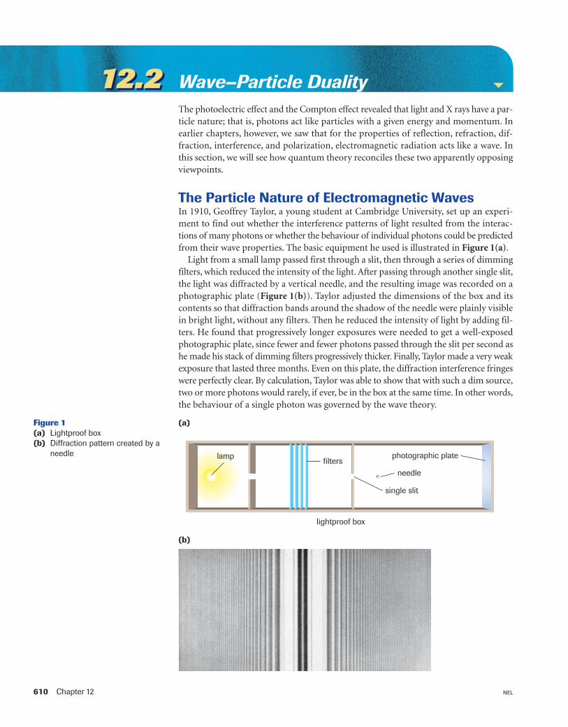
The Particle Nature of Electromagnetic WavesIn 1910, Geoffrey Taylor, a young student at Cambridge University, set up an experi-ment to find out whether the interference patterns of light resulted from the interac-tions of many photons or whether the behaviour of individual photons could be predictedfrom their wave properties. The basic equipment he used is illustrated in Figure 1(a).
Light from a small lamp passed first through a slit, then through a series of dimmingfilters, which reduced the intensity of the light. After passing through another single slit,the light was diffracted by a vertical needle, and the resulting image was recorded on aphotographic plate (Figure 1(b)). Taylor adjusted the dimensions of the box and itscontents so that diffraction bands around the shadow of the needle were plainly visiblein bright light, without any filters. Then he reduced the intensity of light by adding fil-ters. He found that progressively longer exposures were needed to get a well-exposedphotographic plate, since fewer and fewer photons passed through the slit per second ashe made his stack of dimming filters progressively thicker. Finally, Taylor made a very weakexposure that lasted three months. Even on this plate, the diffraction interference fringeswere perfectly clear. By calculation, Taylor was able to show that with such a dim source,two or more photons would rarely, if ever, be in the box at the same time. In other words,the behaviour of a single photon was governed by the wave theory.
filters
lightproof box
photographic plate
single slit
needle
lamp
(a)Figure 1(a) Lightproof box(b) Diffraction pattern created by a
needle
(b)
Waves, Photons, and Matter 611NEL
One way of visualizing the relationship between a photon and its electromagneticwave is to consider that the electromagnetic wave acts as a “guide” that predicts the prob-able behaviour of the photon. The electromagnetic wave determines the chance, or prob-ability, that a photon will be at a certain position in space at a given instant. For a classicalparticle the probability of being in certain places is either 100% (if it is there) or 0% (ifit is not). We do not have this exactness for photons. We only know the probabilitiesdetermined by the electromagnetic wave. Quantum theory assumes that, at any instant,the photon has a probability of being in any position. The probability is greater in thoseregions where the amplitude of the electromagnetic wave interference pattern is greaterand smaller in those regions where the amplitude of the electromagnetic wave interfer-ence pattern is smaller.
If an intense beam of light is directed through two adjacent slits, as in Young’s exper-iment (Section 9.6), a series of alternating bands of constructive and destructive inter-ference is created on the screen. The photons pass through the two slits, and it is theprobability of their arrival on the screen that is predicted by their electromagnetic waves.If two electromagnetic waves interfere destructively, the amplitude is smaller than eitherof the original waves, so the probability of a photon arriving is reduced. When conditionsare such that the resultant amplitude is zero, as it is on a nodal line, the probability offinding a photon is zero. On the other hand, if the two electromagnetic waves interfereconstructively, the resultant amplitude is larger and the probability is high that a photonwill be in that position; that is, a bright area is found.
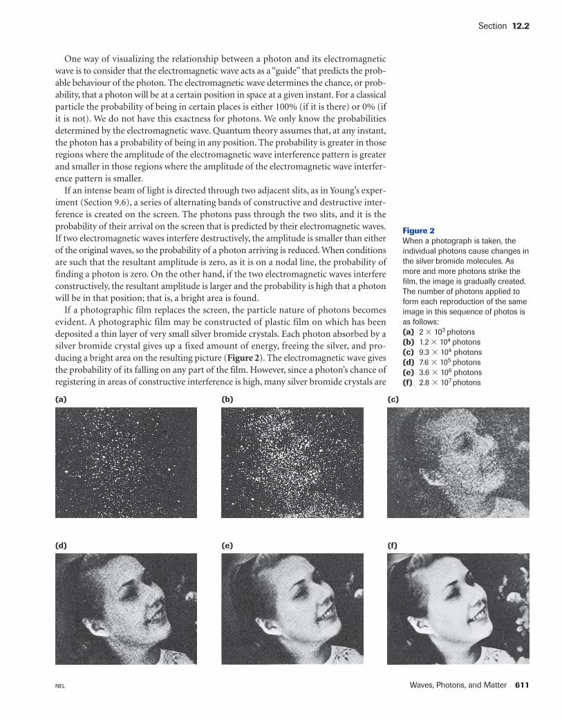
If a photographic film replaces the screen, the particle nature of photons becomesevident. A photographic film may be constructed of plastic film on which has beendeposited a thin layer of very small silver bromide crystals. Each photon absorbed by asilver bromide crystal gives up a fixed amount of energy, freeing the silver, and pro-ducing a bright area on the resulting picture (Figure 2). The electromagnetic wave givesthe probability of its falling on any part of the film. However, since a photon’s chance ofregistering in areas of constructive interference is high, many silver bromide crystals are
Section 12.2
Figure 2When a photograph is taken, theindividual photons cause changes inthe silver bromide molecules. Asmore and more photons strike thefilm, the image is gradually created.The number of photons applied toform each reproduction of the sameimage in this sequence of photos isas follows: (a) 2 � 103 photons (b) 1.2 � 104 photons (c) 9.3 � 104 photons (d) 7.6 � 105 photons (e) 3.6 � 106 photons (f) 2.8 � 107 photons
(a) (b) (c)
(d) (e) (f)
612 Chapter 12 NEL
changed in these areas, and a bright area will be recorded on the image. In areas of near-total destructive interference, fewer crystals are changed, and a relatively dark area willbe recorded on the image. On the nodal lines, no crystals change at all.
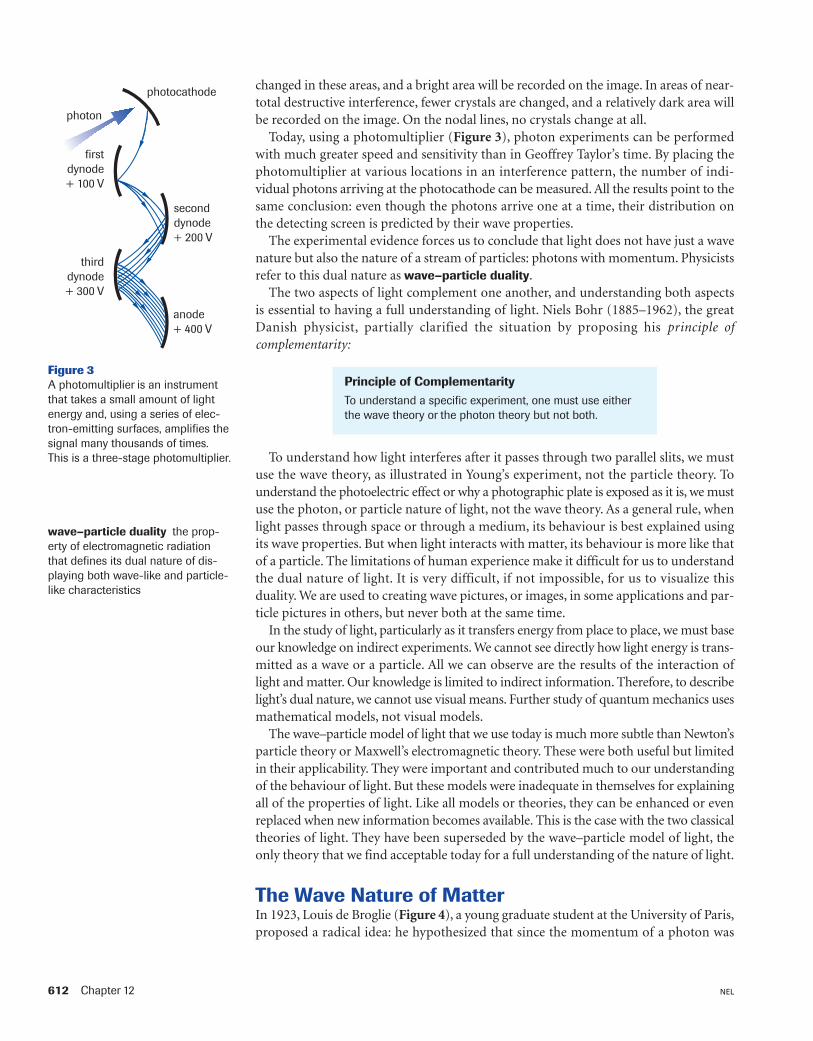
Today, using a photomultiplier (Figure 3), photon experiments can be performedwith much greater speed and sensitivity than in Geoffrey Taylor’s time. By placing thephotomultiplier at various locations in an interference pattern, the number of indi-vidual photons arriving at the photocathode can be measured. All the results point to thesame conclusion: even though the photons arrive one at a time, their distribution onthe detecting screen is predicted by their wave properties.
The experimental evidence forces us to conclude that light does not have just a wavenature but also the nature of a stream of particles: photons with momentum. Physicistsrefer to this dual nature as wave–particle duality.
The two aspects of light complement one another, and understanding both aspects is essential to having a full understanding of light. Niels Bohr (1885–1962), the greatDanish physicist, partially clarified the situation by proposing his principle ofcomplementarity:
photocathode
photon
seconddynode+ 200 V
thirddynode+ 300 V
firstdynode+ 100 V
anode+ 400 V
Figure 3A photomultiplier is an instrumentthat takes a small amount of lightenergy and, using a series of elec-tron-emitting surfaces, amplifies thesignal many thousands of times.This is a three-stage photomultiplier.
wave–particle duality the prop-erty of electromagnetic radiationthat defines its dual nature of dis-playing both wave-like and particle-like characteristics
Principle of ComplementarityTo understand a specific experiment, one must use eitherthe wave theory or the photon theory but not both.
To understand how light interferes after it passes through two parallel slits, we mustuse the wave theory, as illustrated in Young’s experiment, not the particle theory. Tounderstand the photoelectric effect or why a photographic plate is exposed as it is, we mustuse the photon, or particle nature of light, not the wave theory. As a general rule, whenlight passes through space or through a medium, its behaviour is best explained usingits wave properties. But when light interacts with matter, its behaviour is more like thatof a particle. The limitations of human experience make it difficult for us to understandthe dual nature of light. It is very difficult, if not impossible, for us to visualize thisduality. We are used to creating wave pictures, or images, in some applications and par-ticle pictures in others, but never both at the same time.
In the study of light, particularly as it transfers energy from place to place, we must baseour knowledge on indirect experiments. We cannot see directly how light energy is trans-mitted as a wave or a particle. All we can observe are the results of the interaction oflight and matter. Our knowledge is limited to indirect information. Therefore, to describelight’s dual nature, we cannot use visual means. Further study of quantum mechanics usesmathematical models, not visual models.
The wave–particle model of light that we use today is much more subtle than Newton’sparticle theory or Maxwell’s electromagnetic theory. These were both useful but limitedin their applicability. They were important and contributed much to our understandingof the behaviour of light. But these models were inadequate in themselves for explainingall of the properties of light. Like all models or theories, they can be enhanced or evenreplaced when new information becomes available. This is the case with the two classicaltheories of light. They have been superseded by the wave–particle model of light, theonly theory that we find acceptable today for a full understanding of the nature of light.
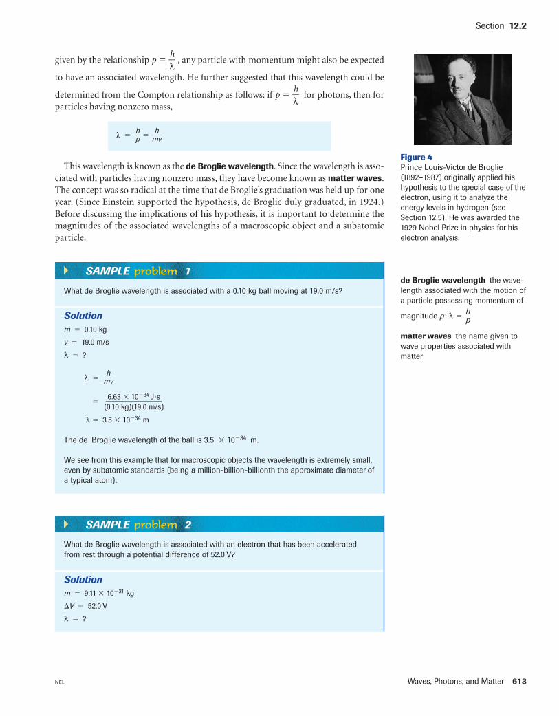
The Wave Nature of MatterIn 1923, Louis de Broglie (Figure 4), a young graduate student at the University of Paris,proposed a radical idea: he hypothesized that since the momentum of a photon was
Waves, Photons, and Matter 613NEL
Section 12.2
λ � �hp� � �m
hv�
given by the relationship p � �λh
� , any particle with momentum might also be expected
to have an associated wavelength. He further suggested that this wavelength could be
determined from the Compton relationship as follows: if p � �λh
� for photons, then forparticles having nonzero mass,
Figure 4Prince Louis-Victor de Broglie(1892–1987) originally applied hishypothesis to the special case of theelectron, using it to analyze theenergy levels in hydrogen (seeSection 12.5). He was awarded the1929 Nobel Prize in physics for hiselectron analysis.
de Broglie wavelength the wave-length associated with the motion ofa particle possessing momentum of
magnitude p : λ � �hp�
matter waves the name given towave properties associated withmatter
This wavelength is known as the de Broglie wavelength. Since the wavelength is asso-ciated with particles having nonzero mass, they have become known as matter waves.The concept was so radical at the time that de Broglie’s graduation was held up for oneyear. (Since Einstein supported the hypothesis, de Broglie duly graduated, in 1924.)Before discussing the implications of his hypothesis, it is important to determine themagnitudes of the associated wavelengths of a macroscopic object and a subatomic particle.
What de Broglie wavelength is associated with a 0.10 kg ball moving at 19.0 m/s?
Solutionm � 0.10 kg
v � 19.0 m/s
λ � ?
λ � �mhv�
�
λ � 3.5 � 10�34 m
The de Broglie wavelength of the ball is 3.5 � 10�34 m.
We see from this example that for macroscopic objects the wavelength is extremely small,even by subatomic standards (being a million-billion-billionth the approximate diameter ofa typical atom).
6.63 � 10�34 J�s��(0.10 kg)(19.0 m/s)
SAMPLE problem 1
What de Broglie wavelength is associated with an electron that has been acceleratedfrom rest through a potential difference of 52.0 V?
Solutionm � 9.11 � 10�31 kg
�V � 52.0 V
λ � ?
SAMPLE problem 2
614 Chapter 12 NEL
Answers
1. (a) 2.2 � 10�35 m
(b) 3.0 � 10�12 m
(c) 1.5 � 10�8 m
2. 4.1 � 10�7 m; 5.5 � 10�10 m
3. 2.7 � 10�36 m
4. 67 eV
5. 1.23 � 10�10 m
6. (a) 6.6 � 10�24 kg�m/s
(b) 7.3 � 106 m/s
(c) 2.4 � 10�17 J, or 1.5 � 102 eV
�V � ��
qEe�
�Ee � q�V
The loss of electric potential energy is equivalent to the gain in the electron’s kinetic energy.
�EK � �Ee
For an electron
EK � e�V
� (1.60 � 10�19 C)(52.0 J/C)
EK � 8.32 � 10�18 J
But EK � �12
�mv2
v � ��� ���
v � 4.27 � 106 m/s
Then λ � �mhv�
�
λ � 1.70 � 10�10 m
The de Broglie wavelength of the electron is 1.70 � 10�10 m.
We see from this example that while for a low-momentum subatomic particle such as anelectron the de Broglie wavelength is still small, it is no longer very small. For example, thediameter of a hydrogen atom is approximately 1.0 � 10�10 m, that is, less than the deBroglie wavelength associated with an electron. This is an issue of great importance, towhich we will return in Section 12.5.
6.63 � 10�34 J�s����(9.11 � 10�31 kg)(4.27 � 106 m/s)
2(8.32 � 10�18 J)��9.11 � 10�31 kg
2EK�m
PracticeUnderstanding Concepts
1. Calculate the de Broglie wavelength associated with each of the following:(a) a 2.0-kg ball thrown at 15 m/s(b) a proton accelerated to 1.3 � 105 m/s(c) an electron moving at 5.0 � 104 m/s
2. Calculate the associated wavelengths, in metres, of a 3.0-eV photon and a 5.0-eV electron.
3. Calculate the de Broglie wavelength associated with an artillery shell having amass of 0.50 kg and a speed of 5.00 � 102 m/s.
4. Calculate the energy, in electron volts, required to give an electron an associ-ated de Broglie wavelength of 0.15 nm.
5. An electron is accelerated through a potential difference of 1.00 � 102 V.Calculate the associated de Broglie wavelength.
6. (a) Calculate the momentum of an electron that has an associated de Brogliewavelength of 1.0 � 10�10 m.
(b) Calculate the speed of the same electron.(c) Calculate the kinetic energy of the same electron.
Waves, Photons, and Matter 615NEL
Matter WavesWe saw in the preceding problems that the matter wavelengths of most ordinary objects,such as baseballs, are exceedingly small, even on atomic scales. We also saw that thematter wavelengths of objects such as electrons are small on macroscopic scales butappreciable on atomic scales (being comparable, in fact, with the wavelengths of someX rays). Recall that the wave nature of light was elusive until the time of Young becauselight has such short wavelengths. The matter wavelengths of macroscopic objects are sosmall they preclude detection. For subatomic particles, the matter wavelengths are stillsmall enough to make detection challenging.
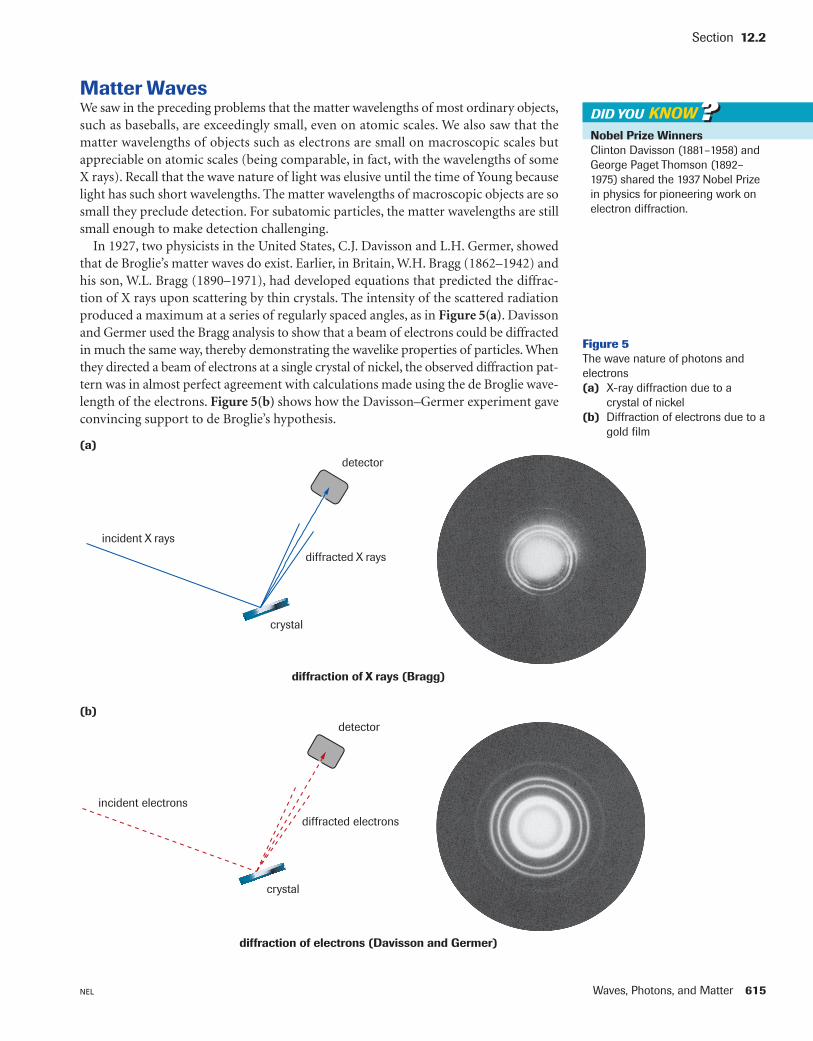
In 1927, two physicists in the United States, C.J. Davisson and L.H. Germer, showedthat de Broglie’s matter waves do exist. Earlier, in Britain, W.H. Bragg (1862–1942) andhis son, W.L. Bragg (1890–1971), had developed equations that predicted the diffrac-tion of X rays upon scattering by thin crystals. The intensity of the scattered radiationproduced a maximum at a series of regularly spaced angles, as in Figure 5(a). Davissonand Germer used the Bragg analysis to show that a beam of electrons could be diffractedin much the same way, thereby demonstrating the wavelike properties of particles. Whenthey directed a beam of electrons at a single crystal of nickel, the observed diffraction pat-tern was in almost perfect agreement with calculations made using the de Broglie wave-length of the electrons. Figure 5(b) shows how the Davisson–Germer experiment gaveconvincing support to de Broglie’s hypothesis.
Section 12.2
Nobel Prize WinnersClinton Davisson (1881–1958) andGeorge Paget Thomson (1892–1975) shared the 1937 Nobel Prizein physics for pioneering work onelectron diffraction.
DID YOU KNOW ??
incident X rays
crystal
diffracted X rays
detector
Figure 5The wave nature of photons andelectrons(a) X-ray diffraction due to a
crystal of nickel (b) Diffraction of electrons due to a
gold film(a)
incident electrons
crystal
diffracted electrons
detector(b)
diffraction of X rays (Bragg)
diffraction of electrons (Davisson and Germer)
616 Chapter 12 NEL
In the same year, 1927, G.P. Thomson, in Britain, passed a beam of electrons througha thin metal foil. The diffraction pattern was the same as for X rays, once the correctwavelength was taken into account. The Davisson–Germer and Thomson experimentsleft little doubt that particles exhibit wavelike properties. Later experiments using pro-tons, neutrons, helium nuclei, and other particles produced similar results. Quantummechanics, the mathematical interpretation of the structure and interactions of matterbased on the concept that particles have a wave nature, was vindicated.
The wave–particle duality for small particles matched the wave–particle duality for thephoton, as worked out by Compton. The principle of complementarity thus applies tomatter as well as to radiation. We may now ask, as we did for light, under what generalconditions does matter reveal its wavelike properties? Recall that for the wave propertyof diffraction to be evident in optics, an aperture comparable to the wavelength of lightis needed. Otherwise, the light behaved like a beam of particles moving in a straight linethrough an opening or past an obstacle, showing little diffraction or interference. A sim-ilar requirement holds for matter waves.
Ordinary objects, such as baseballs, have associated matter waves whose wavelengthis extremely short compared with the dimensions of other objects or openings that theyencounter. Therefore, they act like particles, concealing their wave nature. Subatomicparticles such as electrons, by contrast, have associated matter waves whose wavelengthis of the same order of magnitude as the objects with which they interact. As a result, theyproduce diffraction patterns large enough to be observed.
What about the conceptual interpretation of matter waves? Like electromagneticwaves, matter waves predict the probability that a particle will follow a particular paththrough space. It is important to note that matter waves do not carry energy. They onlypredict behaviour. The particle carries the energy.
The fact that wave–particle duality exists for both matter and light reinforced Einstein’scontention (Section 11.4) that mass is interconvertible with energy, under the relation-ship E � mc2. By 1927, the concept that mass and energy were interrelated did not seemas astonishing as it had when Einstein proposed it in 1905. Furthermore, the wave char-acteristics of the electrons orbiting the nucleus of an atom could now be examined usingquantum mechanics (see Section 12.5).
Electron MicroscopesThe resolution of an ordinary microscope is limited by the wavelength of the light used.The highest useful magnification obtainable, with an oil-immersion objective, is 2000×,with the best resolution approximately 2.0 � 10�7 m (about one-half the wavelength ofvisible light). On the other hand, a beam of electrons having an associated de Broglie wave-length of less than 1.0 nm could produce a resolution of approximately 0.5 nm. Thismeans that if one could get electrons to behave as light does in a microscope, the mag-nification could be increased to as high as 2 million times or more.
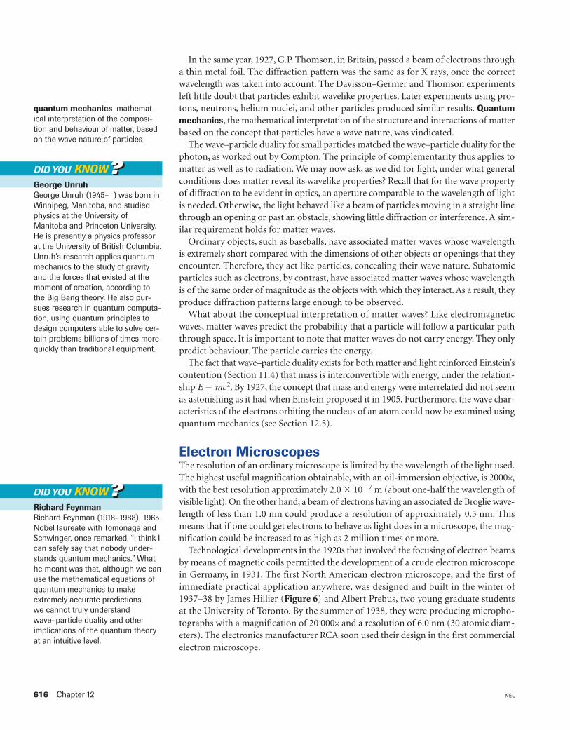
Technological developments in the 1920s that involved the focusing of electron beamsby means of magnetic coils permitted the development of a crude electron microscopein Germany, in 1931. The first North American electron microscope, and the first ofimmediate practical application anywhere, was designed and built in the winter of1937–38 by James Hillier (Figure 6) and Albert Prebus, two young graduate studentsat the University of Toronto. By the summer of 1938, they were producing micropho-tographs with a magnification of 20 000× and a resolution of 6.0 nm (30 atomic diam-eters). The electronics manufacturer RCA soon used their design in the first commercialelectron microscope.
quantum mechanics mathemat-ical interpretation of the composi-tion and behaviour of matter, basedon the wave nature of particles
George UnruhGeorge Unruh (1945– ) was born inWinnipeg, Manitoba, and studiedphysics at the University ofManitoba and Princeton University.He is presently a physics professorat the University of British Columbia.Unruh’s research applies quantummechanics to the study of gravityand the forces that existed at themoment of creation, according tothe Big Bang theory. He also pur-sues research in quantum computa-tion, using quantum principles todesign computers able to solve cer-tain problems billions of times morequickly than traditional equipment.
DID YOU KNOW ??
Richard FeynmanRichard Feynman (1918–1988), 1965Nobel laureate with Tomonaga andSchwinger, once remarked, “I think Ican safely say that nobody under-stands quantum mechanics.” Whathe meant was that, although we canuse the mathematical equations ofquantum mechanics to makeextremely accurate predictions, we cannot truly understandwave–particle duality and otherimplications of the quantum theoryat an intuitive level.
DID YOU KNOW ??
Waves, Photons, and Matter 617NEL
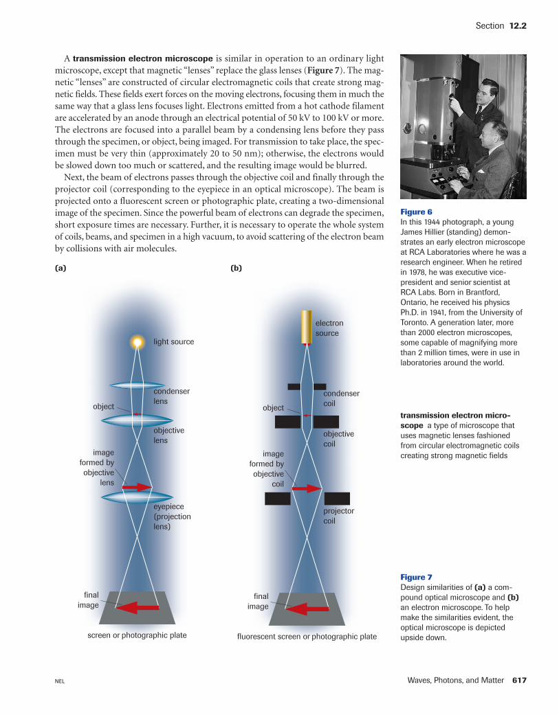
A transmission electron microscope is similar in operation to an ordinary lightmicroscope, except that magnetic “lenses” replace the glass lenses (Figure 7). The mag-netic “lenses” are constructed of circular electromagnetic coils that create strong mag-netic fields. These fields exert forces on the moving electrons, focusing them in much thesame way that a glass lens focuses light. Electrons emitted from a hot cathode filamentare accelerated by an anode through an electrical potential of 50 kV to 100 kV or more.The electrons are focused into a parallel beam by a condensing lens before they passthrough the specimen, or object, being imaged. For transmission to take place, the spec-imen must be very thin (approximately 20 to 50 nm); otherwise, the electrons wouldbe slowed down too much or scattered, and the resulting image would be blurred.
Next, the beam of electrons passes through the objective coil and finally through theprojector coil (corresponding to the eyepiece in an optical microscope). The beam isprojected onto a fluorescent screen or photographic plate, creating a two-dimensionalimage of the specimen. Since the powerful beam of electrons can degrade the specimen,short exposure times are necessary. Further, it is necessary to operate the whole systemof coils, beams, and specimen in a high vacuum, to avoid scattering of the electron beamby collisions with air molecules.
Section 12.2
Figure 6In this 1944 photograph, a youngJames Hillier (standing) demon-strates an early electron microscopeat RCA Laboratories where he was aresearch engineer. When he retiredin 1978, he was executive vice-president and senior scientist atRCA Labs. Born in Brantford,Ontario, he received his physicsPh.D. in 1941, from the University ofToronto. A generation later, morethan 2000 electron microscopes,some capable of magnifying morethan 2 million times, were in use inlaboratories around the world.
transmission electron micro-scope a type of microscope thatuses magnetic lenses fashionedfrom circular electromagnetic coilscreating strong magnetic fields
screen or photographic plate
finalimage
eyepiece(projectionlens)
objectivelens
condenserlens
light source
imageformed byobjective
lens
object
(a)
Figure 7Design similarities of (a) a com-pound optical microscope and (b)an electron microscope. To helpmake the similarities evident, theoptical microscope is depictedupside down.fluorescent screen or photographic plate
finalimage
projectorcoil
objectivecoil
condensercoil
electronsource
imageformed byobjective
coil
object
(b)
618 Chapter 12 NEL
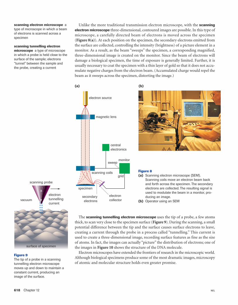
Unlike the more traditional transmission electron microscope, with the scanningelectron microscope three-dimensional, contoured images are possible. In this type ofmicroscope, a carefully directed beam of electrons is moved across the specimen(Figure 8(a)). At each position on the specimen, the secondary electrons emitted fromthe surface are collected, controlling the intensity (brightness) of a picture element in amonitor. As a result, as the beam “sweeps” the specimen, a corresponding magnified,three-dimensional image is created on the monitor. Since the beam of electrons willdamage a biological specimen, the time of exposure is generally limited. Further, it isusually necessary to coat the specimen with a thin layer of gold so that it does not accu-mulate negative charges from the electron beam. (Accumulated charge would repel thebeam as it sweeps across the specimen, distorting the image.)
monitorsweep
grid
centralelectronics
scanning coils
magnetic lens
electron source
electroncollector
secondaryelectrons
specimen
(a)
Figure 8(a) Scanning electron microscope (SEM).
Scanning coils move an electron beam backand forth across the specimen. The secondaryelectrons are collected. The resulting signal isused to modulate the beam in a monitor, pro-ducing an image.
(b) Operator using an SEM
(b)
scanning probe
surface of specimen
vacuumelectrontunnellingcurrent
Figure 9The tip of a probe in a scanningtunnelling electron microscopemoves up and down to maintain aconstant current, producing animage of the surface.
scanning electron microscope atype of microscope in which a beamof electrons is scanned across aspecimen
scanning tunnelling electronmicroscope a type of microscopein which a probe is held close to thesurface of the sample; electrons“tunnel” between the sample andthe probe, creating a current
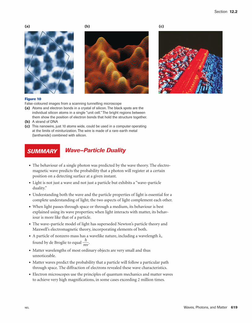
The scanning tunnelling electron microscope uses the tip of a probe, a few atomsthick, to scan very close to the specimen surface (Figure 9). During the scanning, a smallpotential difference between the tip and the surface causes surface electrons to leave,creating a current through the probe in a process called “tunnelling.” This current isused to create a three-dimensional image, recording surface features as fine as the sizeof atoms. In fact, the images can actually “picture” the distribution of electrons; one ofthe images in Figure 10 shows the structure of the DNA molecule.
Electron microscopes have extended the frontiers of research in the microscopic world.Although biological specimens produce some of the most dramatic images, microscopyof atomic and molecular structure holds even greater promise.
Waves, Photons, and Matter 619NEL
Section 12.2
(a) (b) (c)
Figure 10False-coloured images from a scanning tunnelling microscope(a) Atoms and electron bonds in a crystal of silicon. The black spots are the
individual silicon atoms in a single “unit cell.” The bright regions betweenthem show the position of electron bonds that hold the structure together.
(b) A strand of DNA(c) This nanowire, just 10 atoms wide, could be used in a computer operating
at the limits of miniturization. The wire is made of a rare-earth metal (lanthanide) combined with silicon.
• The behaviour of a single photon was predicted by the wave theory. The electro-magnetic wave predicts the probability that a photon will register at a certainposition on a detecting surface at a given instant.
• Light is not just a wave and not just a particle but exhibits a “wave–particleduality.”
• Understanding both the wave and the particle properties of light is essential for acomplete understanding of light; the two aspects of light complement each other.
• When light passes through space or through a medium, its behaviour is bestexplained using its wave properties; when light interacts with matter, its behav-iour is more like that of a particle.
• The wave–particle model of light has superseded Newton’s particle theory andMaxwell’s electromagnetic theory, incorporating elements of both.
• A particle of nonzero mass has a wavelike nature, including a wavelength λ,
found by de Broglie to equal �mhv�.
• Matter wavelengths of most ordinary objects are very small and thus unnoticeable.
• Matter waves predict the probability that a particle will follow a particular paththrough space. The diffraction of electrons revealed these wave characteristics.
• Electron microscopes use the principles of quantum mechanics and matter wavesto achieve very high magnifications, in some cases exceeding 2 million times.
Wave–Particle DualitySUMMARY

620 Chapter 12 NEL
Section 12.2 QuestionsUnderstanding Concepts
1. Describe one type of evidence for(a) the wave nature of matter(b) the particle nature of electromagnetic radiation
2. Explain how the equations for single-slit diffraction can beused to predict the behaviour of a photon passing througha single slit.
3. Compare and contrast a 2-eV electron and a 2-eV photon,citing at least four properties of each.
4. Calculate the associated de Broglie wavelength of(a) a neutron travelling at 1.5 � 104 m/s
(mn � 1.67 � 10�27 kg) (b) an electron travelling at 1.2 � 106 m/s
(me � 9.11 � 10�31 kg) (c) a proton with kinetic energy 1.0 � 109 eV
(mp � 1.67 � 10�27 kg)
5. An electron beam in a certain electron microscope haselectrons with individual kinetic energies of 5.00 � 104 eV.Calculate the de Broglie wavelength of such electrons.
6. Calculate the momentum and the equivalent mass of a 0.20 nm X-ray photon. (This does not imply a photon hasmass!)
7. A certain microscopic object has a speed of 1.2 � 105 m/s.Its associated de Broglie wavelength is 8.4 � 10�14 m.Calculate its mass.
8. What would the slit width have to be before the matterwave effects would be noticeable for a 5.0-eV electronpassing through the single slit?
9. A proton emerges from a Van de Graaff accelerator with aspeed that is 25.0% the speed of light. Assuming, contraryto fact, that the proton can be treated nonrelativistically,calculate(a) the associated de Broglie wavelength(b) the kinetic energy(c) the potential difference through which the proton was
accelerated if it started essentially from rest
10. In a television picture tube, electrons are acceleratedessentially from rest through an appreciable anode-cathode potential difference. Just before an electron strikesthe screen, its associated de Broglie wavelength is 1.0 �10�11 m. Calculate the potential difference.
Making Connections
11. Research the use of tunnelling electron microscopes todetermine the electron distribution in atoms. Write a shortreport on your findings.
12. Research electron microscopes and find out what precau-tions are necessary to protect the sample from damage.
13. In Sections 12.1 and 12.2 you read about two significantaccomplishments by Canadian scientists: Willard Boyle andthe CCD, and James Hillier and the first commercial elec-tron microscope. Choose one of these Canadian scientists(or another of your choosing who has contributed tomodern physics), and prepare a summary that includesbiographical information, the technology, background tothe development of the technology, the physics behind it,and how it contributed to the respective field(s) of scienceand to society. Your summary can be in the form of aresearch paper, a web site, or a pamphlet designed to sellthe technology.
GO www.science.nelson.com
GO www.science.nelson.com
GO www.science.nelson.com