120sc - 225 self colleting drill - j & j tooling · 1 operation & service manual 823004...
TRANSCRIPT

1
Operation & Service Manual823004 12/01
120SC - 225 SELF COLLETING DRILL
Houston Operation7007 PinemontHouston, TX 77040
Recoules OperationZone industrielle - B.P. 28Avenue Maurice Chevalier77831 Ozoir-la-Ferriere Cedex France

2

3
• Before the tool is connected to the air supply, the throttle should be checked for proper operation (i.e., throttle valve moves freely and returns to closed position).
• Before removing a tool from service or changing drill bits, make sure the air line is shut off and drained of air. This will prevent the tool from operating if the throttle is accidently engaged.
• Cutting tools used with these drill motors are sharp. Handle them carefully to avoid injury.
• The collet and mandrel must be inserted into a properly sized pre-drilled hole before starting the tool. An improperly sized pre- drilled hole prevents the mandrel from engaging the collet and could result in slippage of the tool. An improperly selected collet and mandrel can also result in slippage of the tool.
Drilling or other use of this tool may produce hazardous fumesand/or dust. To avoid adverse health effects utilize adequateventilation and/or a respirator. Read the material safety datasheet of any cutting fluids or materials involved in the drillingprocess.
Some non-ferrous metal chips (or dusts) are combustible. Ex-amples: Aluminum, magnesium, Titanium, and Zirconium. Seethe material safety data sheets for combustibility of materialsdrilled. Never collect spark generating material with combustiblematerial. Examples: Collecting both steel and aluminum or steeland titanium.
Quackenbush drills are often used with lubricant or coolingsystems which must be properly maintained to avoid leakage.Failure to do so can result in serious injuries from slipping on oilysurfaces.
For your safety and the safety of others, read and understandthe safety recommendations and operating instructions be-fore operating any drill motor.
Always wear protective equipment:
For additional information on eye protection, read the latest editionof ANSI Z87.1, Occupational and Educational Eye and FaceProtection. This standard is available from the American NationalStandards Institute, Inc., 11 West 42nd Street, New York, N.Y.10036.
Hearing protection is recommended in high noise areas (above85dBA). Close proximity of additional tools, reflective surfaces,process noises, etc., can contribute substantially to the soundlevel experienced by the operator.
Follow good machine shop practices. Rotating shafts and movingcomponents entangle and entrap, and may result in seriousinjuries. Never wear long hair, loose-fitting clothes, gloves, ties,or jewelry when working with or near a drill of any type.
Quackenbush drills are designed to operate on 90psig (6.2 bar)maximum air pressure using the proper hose. Excessive airpressure increases the loads and stresses on tool parts and drills,and may result in breakage. The installation of a filter-regulator-lubricator in the air supply line ahead of the tool is highly recom-mended.
Safety Recommendations
!
Do not wear loose fitting clothes, long hair, gloves, ties or jewelry.
WARNING
CAUTION!
Personal hearing protection is recommended when operating or working near this tool.
WARNING!
Impact resistant eye protection must be worn while operating or working near this tool.
CAUTION!
WARNING!
Wear respirator where necessary.
CAUTION!
CAUTION!Slip and fall hazard. Lubricant and coolant systems must be properly maintained to avoid leakage. Hoses must be organized and care taken to avoid tripping.

4
Due to the number and variety of tooling applications, the user'smethods engineering departments, ect., must consider any haz-ards that may be associated with each specific application of thisproduct and provide adequate operator protection from inadvert-ent contact with any moving components. The clamping and feedmechanisms of self-colleting drill motors are exposed for visibilityand can move when the air supply is connected or disconnected.To avoid injury, keep fingers and hands away from these areaswhen handling or operating this tool.
Some individuals are susceptible to disorders of the hands andarms when exposed to vibration and/or tasks which involverepetitive work motions. Those individuals predisposed to vascu-latory or circulatory problems may be particularly susceptible.Cumulative trauma disorders such as carpal tunnel syndrome andtendinitis can be caused or aggravated by repetitious, forcefulexertions of the hands and arms. These disorders develop gradu-ally over periods of weeks, months, and years. Tasks should beperformed in such a manner that the wrists are maintained in aneutral position, which is not flexed, hyperextended, or turned sideto side. Stressful postures should be avoided and can be con-trolled through tool selection and work location.
Safety Recommendations
Any tool operator should be aware of the following warning signsand symptoms so that a problem can be addressed before itbecomes a debilitating injury. Any user suffering from prolongedsymptoms of tingling, numbness, blanching of fingers, clumsi-ness or weakened grip, inability to hold objects, nocturnal pain inthe hand, or any other disorder of the shoulders, arms, wrists, orfingers should notify their employer so that a review of what stepsmight be taken to prevent further occurances. These steps mightinclude but are not limited to, repositioning the workpiece orredesigning the workstation, reassigning tool users to other jobs,rotating jobs, changing worker pace, and/or changing the type oftool used so as to minimize stress on the operator. Some tasksmay require more than one type of tool to obtain the optimumoperator/ tool/ task relationship.
The following recommendations will help reduce or moderate theeffects of repetitive work motions. The operator of any drill should:
• Use a minimum hand grip force consistent with proper control and safe operation
• Keep body and hands warm and dry• Avoid anything that inhibits blood circulation
— Smoking Tobacco— Cold Temperatures— Certain Drugs
• Avoid awkward postures• Keep wrists as straight as possible• Interrupt work, activities, or rotate jobs to provide
periods free from repetitive work motions.
WARNING!
Repetitive work motions can injure your hands and arms.
WARNING!
Exposure to vibration can injure your hands and arms.
Extension Neutral Flexion Radial Deviation Neutral Ulnar Deviation
Avoid Avoid AvoidOK Avoid OK
WARNING! Keep hands away from clamping and feedmechanisms. Clamp mechanism moves when drilling and connectingor removing air supply.
5
Safety Recommendations
CA
UTIO
N!
Read operating
instructions beforeoperating tool.
OP
ER
AT
ING
INS
TR
UC
TIO
NS
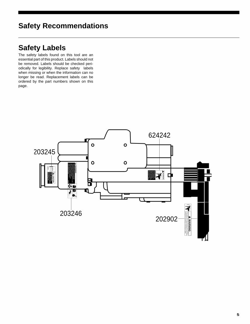
203245
- Wear im
pact re
sis
tan
t eye p
rote
ctio
n.
- Hearin
g p
rote
ctio
n is
reco
mm
en
ded
. - A
vo
id c
on
tact w
ith ro
tatin
g s
pin
dle
or c
utte
r. - W
ear re
sp
irato
r as n
ecessary
. - E
xp
osu
re to
rep
etitiv
e w
ork
mo
tion
a
nd
/or v
ibra
tion
may b
e h
arm
ful
to y
ou
r han
ds a
nd
arm
s.
WA
RN
ING
!
203246
WA
RN
ING
!Keep
han
ds a
way
from
cla
mp
ing
an
d
feed
mech
an
ism
s.
Cla
mp
mech
an
ism
m
oves w
hen
drillin
g
an
d c
on
nectin
g o
r re
mo
vin
g a
ir su
pp
ly.
624242
WA
RN
ING
!K
eep h
ands a
way fro
m th
is are
a w
hen h
andlin
gor o
pera
ting to
ol. C
lam
p m
ech
anism
move
s when
drillin
g a
nd co
nnectin
g o
r rem
ovin
g a
ir supply.
202902
202902
203245
203246
624242
Safety LabelsThe safety labels found on this tool are anessential part of this product. Labels should notbe removed. Labels should be checked peri-odically for legibility. Replace safety labelswhen missing or when the information can nolonger be read. Replacement labels can beordered by the part numbers shown on thispage.
6
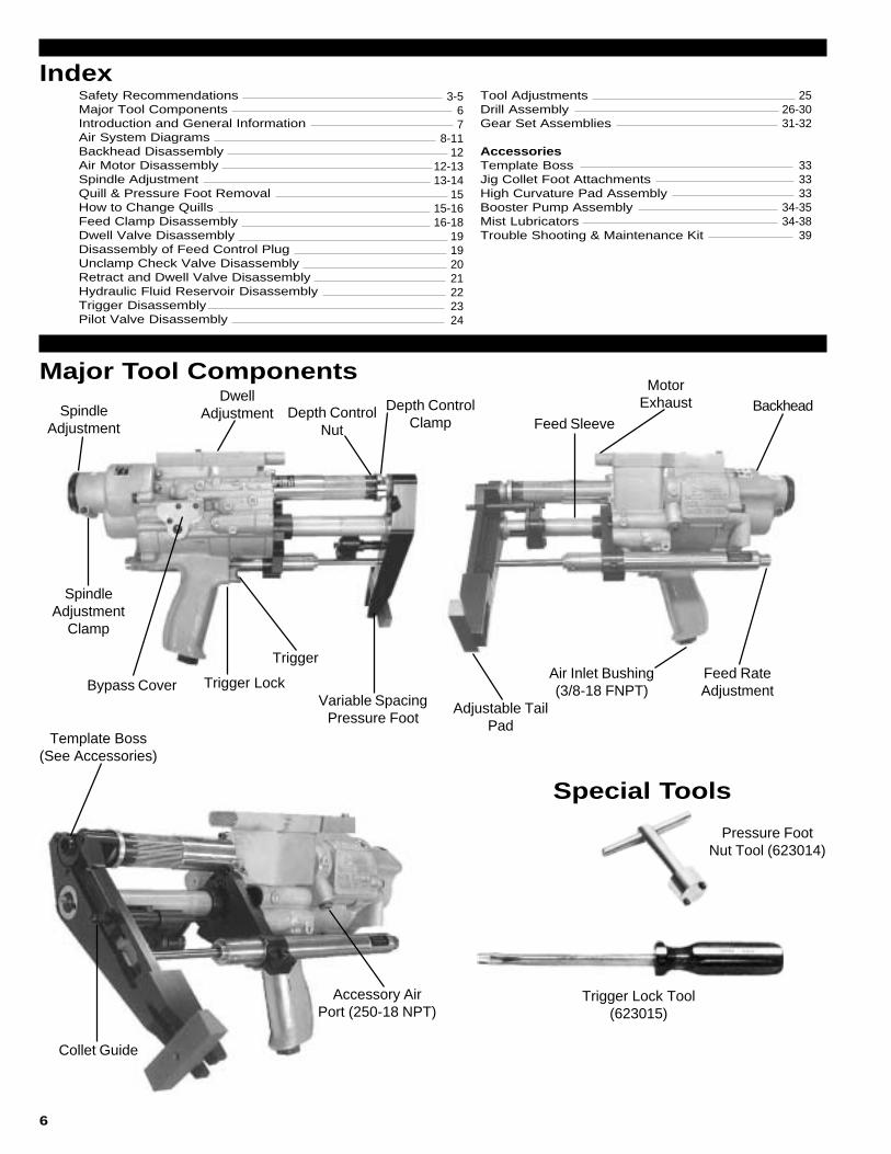
Major Tool Components
Special Tools
Collet Guide
Template Boss(See Accessories)
Accessory AirPort (250-18 NPT)
Adjustable TailPad
Variable SpacingPressure Foot
Bypass CoverFeed RateAdjustment
Backhead
SpindleAdjustment
Clamp
Air Inlet Bushing(3/8-18 FNPT)
MotorExhaust
Feed SleeveSpindle
Adjustment
DwellAdjustment Depth Control
Nut
Depth ControlClamp
Trigger
Trigger Lock
Pressure FootNut Tool (623014)
Trigger Lock Tool(623015)
Tool AdjustmentsDrill AssemblyGear Set Assemblies
AccessoriesTemplate BossJig Collet Foot AttachmentsHigh Curvature Pad AssemblyBooster Pump AssemblyMist LubricatorsTrouble Shooting & Maintenance Kit
3-567
8-1112
12-1313-14
1515-1616-18
19192021222324
2526-3031-32
333333
34-3534-38
39
Safety RecommendationsMajor Tool ComponentsIntroduction and General InformationAir System DiagramsBackhead DisassemblyAir Motor DisassemblySpindle AdjustmentQuill & Pressure Foot RemovalHow to Change QuillsFeed Clamp DisassemblyDwell Valve DisassemblyDisassembly of Feed Control PlugUnclamp Check Valve DisassemblyRetract and Dwell Valve DisassemblyHydraulic Fluid Reservoir DisassemblyTrigger DisassemblyPilot Valve Disassembly
Index

7
The Q-Matic 120SC-225 are air operated, hydraulicallycontrolled tool that automatically clamps to the material,drills and countersinks close tolerance holes in one opera-tion. The Q-Matic will produce high quality holes in alumi-num, steel, titanium and petroleum hybrid materials prima-rily found in the aircraft/aerospace industries. The Q-Maticself-colleting drill motor has been designed using state-of-the-art technology that provides maximum power,minimumweight and the highest degree of accuracy for demandinghole preparation requirements.
Technical DataFeed Stroke: Feed stroke of the Q-Matic 120SC-225 is 2.25inches to drill and countersink in 2 inch stacked material. Thefeed stroke is unaffected by the collet stroke.Collet Stroke: The Q-Matic 120SC-225 will clamp through-out its .875 inch stroke. Collet stroke is unaffected by feedstroke.Spindle Adjustment: The spindle adjustment of .375 inchallows for drill length variations. See Spindle Adjustmentinformation on page 25.Countersink Depth Control: A micrometer adjustmentprovides for countersink stop repeatability within .001 inch.Cutter Sizes: The Q-Matic 120SC-225 will accommodate.500 diameter drills without countersink and.781 counter-sink diameter.Feed Rate: An adjustable drill feed rate mechanism enablesthe Q-Matic 120SC-225 to drill from 5 seconds per inch to 1minute per inch. See Feed Rate Adjustment information onpage 25.Cutter to Collet Spacing: The cutter to collet distance isadjustable between 1.00 inch minimum to 3.50 inch maxi-mum.Coolant: The Q-Matic 120SC-225 has a drill point coolantport in the pressure foot. A coolant mist lubricator is available(See Accessories Page 33-34)Air Motor: The air motor for the 120SC-225 is rated at 1.2horsepower nominal when supplied with air at 90 p.s.i.
Air Consumption: Air consumption of the Q-Matic 120SC-225 is 45 c.f.m. at 90 p.s.i. dynamic.Weight: 15SC-225 weight with the aluminum pressure footis 13 pounds.Spindle Speeds: Eleven geared spindle speeds are avail-
able with the 120SC-225: 270, 470, 700, 900, 1,150, 2,200,
3,500, 5,500, 7,000, 14,000, 23,5000 RPM. See pages 30thru 31 for gear set assembly configurations. Any gear setcan be used with the 120SC-225 tool. See pages 31 thru 32for gear set assembly configurations.Trigger Lock: A trigger lock is provided which allows the toolto be locked in the "Operate" position. With the lock acti-vated, the tool will run through the clamp, feed and retractcycles, but it will not unclamp or stop the motor until thetrigger lock is manually released.
Tool Start-UpThe Q-Matic 120SC-225 drill is shipped from the factoryequipped to the customer's specifications: spindle RPM,spindle to accommodate cutter type desired, pressure foottype, collet guide to accommodate collet desired and op-tional booster pump (if required).After unpacking, examine the customer-specified equip-ment on the Q-Matic tool to verify type and speed ofcomponents. Attach air line to 3/8-18 NPT inlet bushing. Ifquick disconnect fittings are used, 3/8 in. ID are minimum.The Q-Matic 120SC-225 drill requires a supply of clean 90-100 PSI air. Air consumption is 45 CFM at 90 PSI. The useof the in-line lubricator will provide the proper lubrication forthe air motor and will significantly increase the tool lifeexpectancy.Because O-rings are extensively used to seal systemswithin the tool, the elimination of foreign particles and othercontaminants will reduce the possibility of damage to theseparts. Always inspect O-rings for damage or wear andreplace as required. The use of silicone O-ring lubricant isstrongly recommended during reassembly. The addition ofoil in the air line will also increase motor and valve life as wellas the life of the O-rings. Avoid the use of synthetic lubricantsto prevent damage to O-rings and seals.
Introduction and General Information
WEIGHT
AIR CONSUMPTION
HORSE POWER
O/A LENGTH
STROKE
COLLET STROKE
COUNTERSINK
FEED RATE
SPINDLE SPEEDS
DRILLING THRUST
CLAMP FORCE
SPINDLE ADJUSTMENT
MAX. DRILL SIZES
COLLET FOOT SPACING
SPINDLE
COOLANT
13 LBS. MAX. W/ALUMINUM FOOT
45 C.F.M. @ 90 P.S.I. DYNAMIC
APPROX. 1.2 @ 90 P.S.I.
14.28 IN. MAX AT FULL EXTENSION
2.225 IN. (DRILL & C/SINK 2 IN. STACK)
1.00 IN. (NO LOSS OF FEED STROKE)
COUNTERSINK STOP REPEATS WITHIN .001 IN.
MIN. 5 SEC. PER INCH, MAX 1 MIN. PER INCH
270, 470, 700, 900, 1,150, 2,200, 3,500, 5,500, 7,000, 14,000,
23,5000
300 LBS. MAX. (WITHOUT BOOSTER PUMP)
450 LBS. MIN. CLAMP FORCE (UNREGULATED AIR)
.375 IN. ADJUSTMENT TO ALLOW FOR DRILL LENGTH
VARIATIONS
.500 (NO C/SINK), (.781 C/SINK DIA.)
1.00 IN. MIN. - 3.50 IN. MAX.
.500 IN. DIA. W1/4-28 & 3/8-16 IN. THR'D FOR I.D.
THREAD TYPE DRILLS OR 1/4-28 TAPER-LOK TYPE DRILLS.
AIR BLAST PORT & DRILL POINT PORT IN TEMPLATE STD.,
COOLANT MIST LUBRICATOR AVAILABLE.
Q-matic 120SC-225 DRILL MOTOR SPECIFICIATIONS

8

9

10

11

12

13
14

15

16
17

18
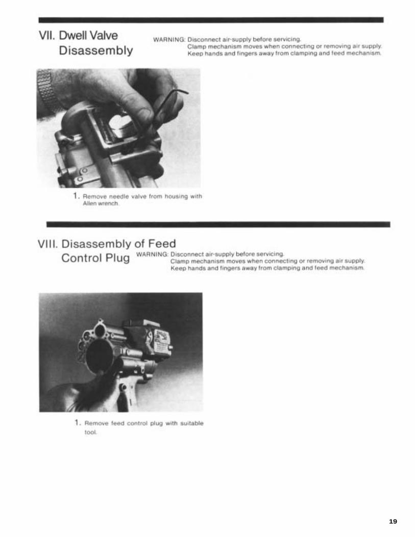
19

20

21

22
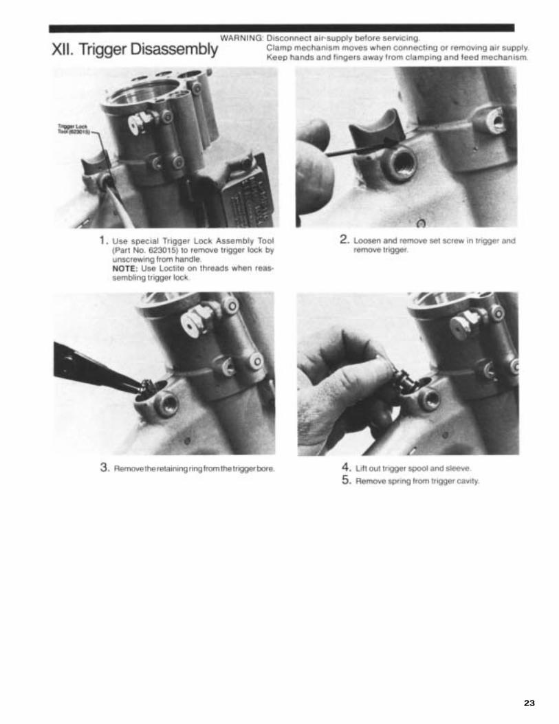
23
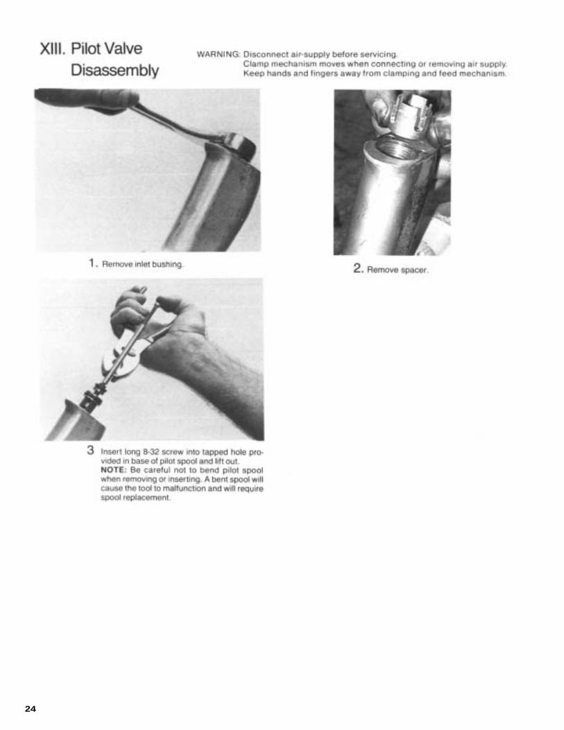
24

25
Tool Adjustments WARNING: Disconnect air-supply before servicing. Clamp mechanism moves when connecting or removing air supply. Keep hands and fingers away from clamping and feed mechanism.
Spindle Stroke AdjustmentLoosen spindle adjustment lock, then turn spindle adjust-ment knob. Right hand rotation advances cutter foward;left hand rotation returns cutter. Correct cutter pointposition is flush with face of template boss. When cutteris properly adjusted, lightly tighten spindle adjustmentlock to hold adjustment.
Micrometer Depth AdjustmentLoosen adjustment clamp, and rotate depth adjustmentnut. Clockwise rotation decreases depth; counterclock-wise increases depth. Graduations scribed on barrel arein .001" increments. When proper depth is achieved.lightly tighten adjustment clamp.
Feed Rate AdjustmentWith appropriate tool, turning feed rate adjustment coun-terclockwise, increase feed rate. Turning the screw clock-wise decreases feed rate. Feed rate can be measured byusing the following formula:
60 secondsTime to drill one inch = ------------------------------------------
Feed Rate x Spindle Speed (rpm)
Dwell AdjustmentInsert appropriate size allen wrench into dwell adjustmentvalve opening. Rotate wrench clockwise until valve seatslightly. Rotate valve counterclockwise 1/2 turn to obtainbase setting.Note: If adjustment valve is opened too far, drill motor willnot cycle, and feed cycle cannot be obtained. To correct,turn valve clockwise to seat valve and set according toinstructions above.
If valve is closed too far, retract cycle cannot be obtained.To correct, turn valve counterclockwise and set accord-ing to instructions.
Closing valve increases countersink dwell time; openingvalve decreases countersink dwell time.
Tail Pad AdjustmentThe purpose of the tail pad is to compensate for slghtsurface curvature of the workpiece being drilling and toassure that the hole being drilled is perpendicular to thesurface.
To adjust to a flat plane for drilling flat surfaces, use astraight edge between the tail pad and face of templateboss and adjust the tail pad until the straight edge is flushwith the face of the template boss.
An optional tail pad is available for high curvature sur-faces. ( See Accessories for more information.)

26
Muffler Subassembly - 641055
13
25
24
11
52
2SCREW, SHC (10-24UNC-3A)6199954
2SCREW, HSBHC (10-32UNF X 1.250)
** PARTS NOT INCLUDED IN SUBASSEMBLY: 632125 - SCREWS
6321255**
1PLENUM6321323
5ELEMENT, MUFFLER6321262
1BOX, MUFFLER6321301
QTY.PART NAMEPART NO.ITEM
15SC Upgrade to 120SC Subassembly - 641099
Part No.
622279622329624973629556632125632128632133632178641055
Name of Part
Spacer, Pilot ValveSubassembly, Pilot ValveFittingSubassembly, Gear Plate SpacerScrew, HSBHC (10-32UNF X 1.250)Screw, IndexingBushing, InletValve, In-line Non returnSubassembly, Muffler
Quanity
111121111

27
844306
844312
623691864271
622252
622254
622253.4166-.4740 DIA.-
.3073-.4114 DIA.-
.1560-.3021 DIA.-
624032624035
PRESSUE FOOT - RIGHT HAND
PRESSUE FOOT - LEFT HAND
SECTION A-ANOT SUPPLIED WITH THIS ASS'Y
COLLET AND MANDREL SHOWN BUT
SPINDLE SET
625646
622688622256
625649625652
625666
622690625647
622777844407
622769
622833621520
625498625085
624036812231
622073622054
622770
844305624016
844310
622861622860
625650624021622773624020
625664622776
624019622774
867745
624018
622778622777
619164
624030863009
623875
ASSEMBLEBACK-TO-BACK
619656
844301622088
622329622280
632133622279
623084
624024622778
844305
622387622697
812963
623848625772
FOR ASSEMBLY INSTRUCTIONS
SEE SPECIFIC GEAR ASSEMBLIES
SPINDLE GEAR SHOWN ONLY
622695615018 864737
641055Muffler Assy. 622779
622698
622780
843791622700
622134

28
C
A
(3 REQ'D)
632128
622056
B
812962622255
C
B625078622358
A
(2 REQ'D)845614623641
622616
622615622618
622617
(3 REQ'D)622775
847710
622376622277
622620
622862847272
(4 REQ'D)
SECTION C-C
622353615645
622353615645
(8 REQ'D)
622376847710622277
622757
844892
624028843434
847272
863454622765
SECTION B-B843518
615645844265
622758
615641
864335
847095
843913812164
624027
622970622642
864236864234
622306619017
847095622759

29
- USE LOCTITE ON TH'DS
847710(2 REQ'D)
612625622384
847710(2 REQ'D)
622250
(4 REQ'D)844407
844303
623881623880623596
(2 REQ'D)
- ASSEMBLY,GEAR SET
(3 REQ'D)
843434
622053
622768
847710
(3 REQ'D)
VIEW D-D
844301622026

30
203245203246624032624035624242612625615018615641615645619017619164619656621620622026622053622054622056622073622088622134622250622255622256622277622279622280622306622329622353622358622376622384622387622615622616622617622618622620622642622688622695622697622698622700622757622758622759622765622768622769622770622773622774622775622776622777622778622779622780622833622860622861622862622970
623084623596623641623691623848623875623880623881624016624018624019624020624021624024624027624028624030624036625078625085625498625645625647625648625649625650625651625652632125632128632133812164812231812962843434843518843791843913844265844301844303844305844306844310844312844407844892845614847095847272847665847710863009863454864234864236864271864335864737867745
Label; cautionLabel; warningPressure foot; rightPressure foot; leftLabel; warningWasher; plainO-ringScrew; bhcO-ringRing; retainingO-ringScrew; sfchcSubassy; bushingValve; needleScrew, bhc (6-32 x .500 lg)Screw; setScrew; shcTriggerSpringKeyPad; pressureCollet guide clipLift lever pinPlugSpacerPistonRotorAssy; pilot valveSpring; compressionPipe; plugRing; retainingScrew; shcSpacerRing; retainingSpringPin; trigger lockBushing; trigger lockSubassy; check valveScrewHolder; colletBulkhead; rearPiston; clamp-unclampNut bearing retainingBearing; ballSubassy; valvePlate; rear bearingPlate; front bearingPlug; reservoirCoverRing; retainingRing; retainingScrew; shcScrew; shcScrew; bhcO-ringO-ringO-ringLocknutWasher; lockCollet springSpring; compressionWasherNon-regulating plugO-ring
Screw; orificeScrew; shcAcorn nutTrigger valve assemblyBackheadNut; spindle adjust.Clamp bushingClamp nutShaft; clampClamp check pistonCover; depth controlNut adjust; depth controlClamp; depth controlCylinder; linerPlug; fluid reservoirPlug; feed controlHandleHydraulic feed control cylinderFlat head cap screwBracket; feed controlBulkhead; frontNut; pressure footBushing; pull rodPull rodClevis pin; linkageClamp-feed shaftLinkage; clevisLift fingerScrew; hsbhc (10-32UNF x 1.250)ScrewBushing; inletPin; springRing; retainingScrew; bhcPlug; pressureScrew; setRing; retainingCollar; rotorBall (1/8)O-ringO-ringO-ringO-ringO-ringO-ringScrew; shcPlug; pipeScrew; sfchcBearing; ballO-ringRing; retainingO-ringO-ringO-ringBlade; rotorCylinderSnap ringBearing capO-ringO-ring
Part No. Part No.Name of Part Name of PartQty. Qty.
11111121141111131311111121111212111111111111211111121331221111112
111111111111111111311111111121111121211212214512221711411111
PARTS LIST

31
623848REF.
621515623772623770623769623771622129812231622134833689622787629556
Assembly, BackheadAssembly, SpacerPlate, Gear SetGear, SpindlePinion, ReductionGear, ReductionBearing, Ball, FlngRing, RetainingKey, WoodruffRing, RetainerScrew, Soc, Hd, CapGear Plate Spacer
Part No. Name of Part Qty.
112111211241
623848REF.
621515622803622800622801622802622129812231622134622787629556
Assembly, BackheadAssembly, SpacerPlate, Gear SetGear, SpindlePinion, ReductionGear, ReductionBearing, Ball, FlngRing, RetainingKey, WoodruffScrew, Soc, Hd, CapGear Plate Spacer
Part No. Name of Part Qty.
11211123141
623848REF.
621515623773623779622801623778622129812231622134622787629556
Assembly, BackheadAssembly, SpacerPlate, Gear SetGear, SpindlePinion, ReductionGear, ReductionBearing, Ball, FlngRing, RetainingKey, WoodruffScrew, Soc, Hd, CapGear Plate Spacer
Part No. Name of Part Qty.
11211123141
623848REF.
621515623774623776622801623777622129812231622134622787629556
Assembly, BackheadAssembly, SpacerPlate, Gear SetGear, SpindlePinion, ReductionGear, ReductionBearing, Ball, FlngRing, RetainingKey, WoodruffScrew, Soc, Hd, CapGear Plate Spacer
Part No. Name of Part Qty.
11211123141
623848REF.
621515622807622806622801622799622129812231622134622787629556
Assembly, BackheadAssembly, SpacerPlate, Gear SetGear, SpindlePinion, ReductionGear, ReductionBearing, Ball, FlngRing, RetainingKey, WoodruffScrew, Soc, Hd, CapGear Plate Spacer
Part No. Name of Part Qty.
11211123141
623848REF.
621515623259623258623257622129812231622787629556
Assembly, BackheadAssembly, SpacerPlate, Gear SetGear, SpindleGear, ReductionBearing, Ball, FlngRing, RetainingScrew, Soc, Hd, CapGear Plate Spacer
Part No. Name of Part Qty.
112112341
Backhead Assembly is shown for reference only and isnot part of the gear assembly. Spindle Gear is not shown,but is supplied loose with assembly. Retainer Ring is usedon the 180 RPM only.
Backhead Assembly is shown for reference only and isnot part of the gear assembly. Spindle Gear is not shown,but is supplied loose with assembly.
Backhead Assembly is shown for reference only and isnot part of the gear assembly. Spindle Gear is not shown,but is supplied loose with assembly.
Backhead Assembly is shown for reference only and isnot part of the gear assembly. Spindle Gear is not shown,but is supplied loose with assembly.
Backhead Assembly is shown for reference only and isnot part of the gear assembly. Spindle Gear is not shown,but is supplied loose with assembly.
Backhead Assembly is shown for reference only and isnot part of the gear assembly. Spindle Gear is not shown,but is supplied loose with assembly.
621835 - 270RPM 621503 - 470RPM
621837 - 700RPM 621836 - 900RPM
621606 - 2,200RPM621504 - 1,150RPM
GEAR SET ASSEMBLIES

32
623848REF.
621515622796622795622784622785622129812231622134622787629556
Assembly, BackheadAssembly, SpacerPlate, Gear SetGear, SpindlePinion, ReductionGear, ReductionBearing, Ball, FlngRing, RetainingKey, WoodruffScrew, Soc, Hd, CapGear Plate Spacer
Part No. Name of Part Qty.
11211123141
623848REF.
621515622805622804622784622785622129812231622134622787629556
Assembly, BackheadAssembly, SpacerPlate, Gear SetGear, SpindlePinion, ReductionGear, ReductionBearing, Ball, FlngRing, RetainingKey, WoodruffScrew, Soc, Hd, CapGear Plate Spacer
Part No. Name of Part Qty.
11211123141
623848REF.
621515622786622783622784622785622129812231622134622787629556
Assembly, BackheadAssembly, SpacerPlate, Gear SetGear, SpindlePinion, ReductionGear, ReductionBearing, Ball, FlngRing, RetainingKey, WoodruffScrew, Soc, Hd, CapGear Plate Spacer
Part No. Name of Part Qty.
11211123141
623848REF.
621515622903622904622784622785622902622129812231622134622787629556
Assembly, BackheadAssembly, SpacerPlate, Gear SetGear, SpindlePinion, ReductionGear, ReductionGear, Pinion OverlayBearing, Ball, FlngRing, RetainingKey, WoodruffScrew, Soc, Hd, CapGear Plate Spacer
Part No. Name of Part Qty.
112111123141
623848REF.
621515622809622804622784622785622902622129812231622134622787629556
Assembly, BackheadAssembly, SpacerPlate, Gear SetGear, SpindlePinion, ReductionGear, ReductionGear, Pinion OverlayBearing, Ball, FlngRing, RetainingKey, WoodruffScrew, Soc, Hd, CapGear Plate Spacer
Part No. Name of Part Qty.
112111123141
Backhead Assembly is shown for reference only and isnot part of the gear assembly. Spindle Gear is not shown,but is supplied loose with assembly.
Backhead Assembly is shown for reference only and isnot part of the gear assembly. Spindle Gear is not shown,but is supplied loose with assembly.
621686 - 5,500RPM621505 - 3,500RPM
Backhead Assembly is shown for reference only and isnot part of the gear assembly. Spindle Gear is not shown,but is supplied loose with assembly.
Backhead Assembly is shown for reference only and isnot part of the gear assembly. Spindle Gear and PinionOverlay Gear are not shown, but is supplied loose withassembly.
621507 - 14,000RPM621506 - 7,000RPM
Backhead Assembly is shown for reference only and isnot part of the gear assembly. Spindle Gear and PinionOverlay Gear are not shown, but is supplied loose withassembly.
621537 - 23,500RPM
2
2
1
1
NOTE POSITION OF GEAR SHOULDER
SHC SCREWSGEAR PLATE
SPACERSPINDLE
GEAR
REDUCTIONGEAR
RETAININGRING
WOODRUFFKEY
GEAR PLATESPACER
RETAINER RINGIS USED ON
270 RPMONLY
BALLBEARING
REDUCTIONPINION GEAR
GEAR SETPLATE
BACKHEAD
ITEM 1 IS FOR REFERENCE ONLY, IT IS NOT PART OF
THE SUBASSEMBLY
-B-

33

34

35
ITEM PART DESCRIPTION NUMBER QTY. NUMBER
1 1 621500 Assembly, Body 2 1 621501 Assembly, End Plate, High Pressure 3 1 622660 End Plate, Low Pressure 4 1 622792 Gasket, End Plate, Low Pressure 5 1 622662 Valve, Pressure Relief 6 1 622663 Piston, Pressure Relief 7 2 622664 Valve,Check 8 1 622665 Valve, Shuttle 9 1 622666 Piston10 1 622652 Spring, Compression, (.34 Length)11 1 622653 Spring, Compression, (.88 Length)12 3 844304 0-ring13 1 625112 Gasket, End Plate, High Pressure14 2 622654 0-ring15 1 844308 0-ring16 1 844315 0-ring17 4 847710 0-ring18 10 863337 Socket Head Cap Screw19 3 617245 Socket Head Cap Screw20 1 622845 Retaining Ring21 3 844303 0-ring22 1 624745 Plug, Booster Pump
INSTALLATION INSTRUCTIONS1. Remove (3) screws No.622050 and cover No.622768 attached to tool.2. Install (2) 0-rings #17 and (2) #21 in booster pump if not already installed.3. Install booster pump No.621482 with (3) screws #19 provided.4. Remove plug, non-regulating No.622862, with slot screwdriver (Refer to service instructions for location).5. Install (2) 0-rings #17 onto booster pump plug #22.6. Install booster pump plug #22.
Booster Pump Assembly 621950
Booster Pump Assembly Instructions

36
PR
ES
SU
RE
FIL
L M
IST
LU
BR
ICA
TOR
Note: x Upper number is item. x Lower number is quantity required.

37
MA
NU
AL
FIL
L M
IST
LU
BR
ICA
TOR
Note: x Upper number is item. x Lower number is quantity required.
38
MO
UN
TIN
G F
OR
MIS
TL
UB
RIC
ATO
R
110
19
16
15
14
13
12
21
28
TO MOTOR
TO DSJC FOOT
TO NDSJC FOOT
TO TEMPLATE FOOT
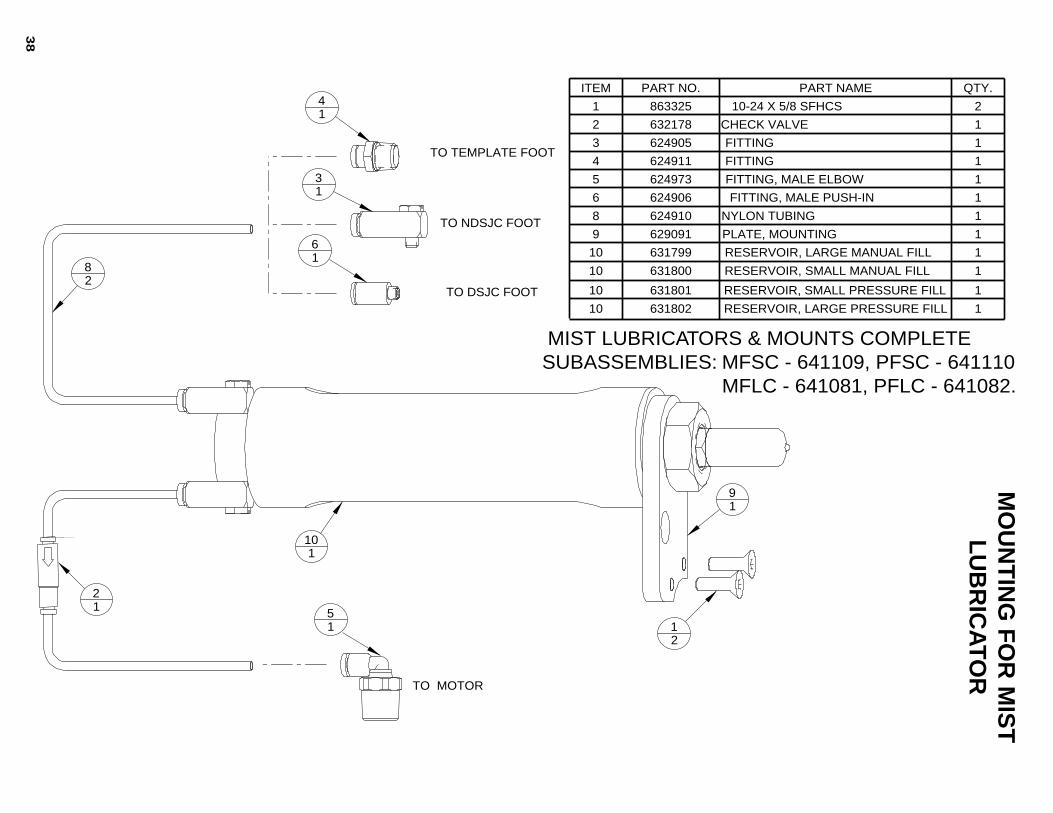
1RESERVOIR, SMALL MANUAL FILL63180010
1RESERVOIR, LARGE MANUAL FILL63179910
1PLATE, MOUNTING6290919
1NYLON TUBING6249108
1FITTING, MALE PUSH-IN6249066
1FITTING, MALE ELBOW6249735
1FITTING6249114
1FITTING6249053
1CHECK VALVE6321782
210-24 X 5/8 SFHCS8633251
QTY.PART NAMEPART NO.ITEM
1RESERVOIR, LARGE PRESSURE FILL63180210
1RESERVOIR, SMALL PRESSURE FILL63180110
MIST LUBRICATORS & MOUNTS COMPLETE SUBASSEMBLIES: MFSC - 641109, PFSC - 641110 MFLC - 641081, PFLC - 641082.
39
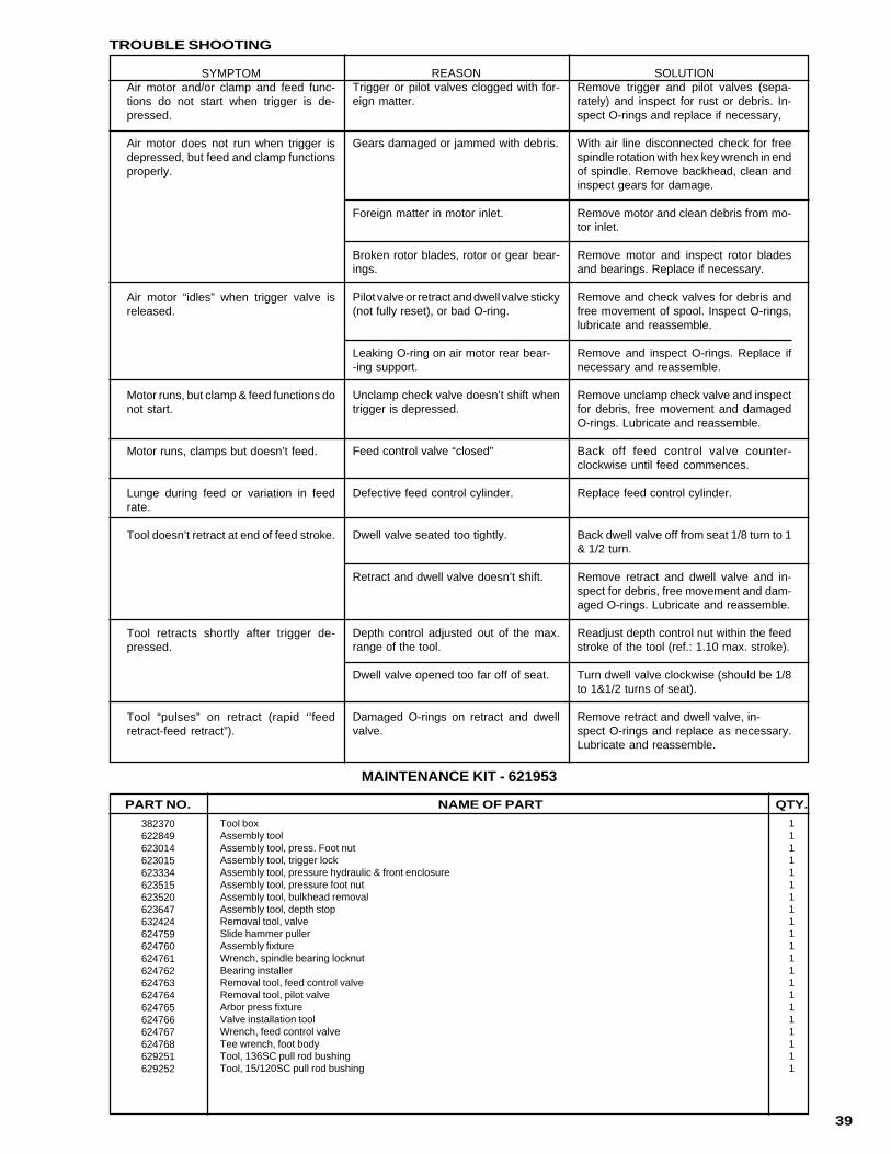
382370622849623014623015623334623515623520623647632424624759624760624761624762624763624764624765624766624767624768629251629252
Tool boxAssembly toolAssembly tool, press. Foot nutAssembly tool, trigger lockAssembly tool, pressure hydraulic & front enclosureAssembly tool, pressure foot nutAssembly tool, bulkhead removalAssembly tool, depth stopRemoval tool, valveSlide hammer pullerAssembly fixtureWrench, spindle bearing locknutBearing installerRemoval tool, feed control valveRemoval tool, pilot valveArbor press fixtureValve installation toolWrench, feed control valveTee wrench, foot bodyTool, 136SC pull rod bushingTool, 15/120SC pull rod bushing
111111111111111111111
QTY.NAME OF PARTPART NO.
MAINTENANCE KIT - 621953
SYMPTOMAir motor and/or clamp and feed func-tions do not start when trigger is de-pressed.
Air motor does not run when trigger isdepressed, but feed and clamp functionsproperly.
Air motor “idles” when trigger valve isreleased.
Motor runs, but clamp & feed functions donot start.
Motor runs, clamps but doesn’t feed.
Lunge during feed or variation in feedrate.
Tool doesn’t retract at end of feed stroke.
Tool retracts shortly after trigger de-pressed.
Tool “pulses” on retract (rapid ‘’feedretract-feed retract”).
REASONTrigger or pilot valves clogged with for-eign matter.
Gears damaged or jammed with debris.
Foreign matter in motor inlet.
Broken rotor blades, rotor or gear bear-ings.
Pilot valve or retract and dwell valve sticky(not fully reset), or bad O-ring.
Leaking O-ring on air motor rear bear--ing support.
Unclamp check valve doesn’t shift whentrigger is depressed.
Feed control valve “closed”
Defective feed control cylinder.
Dwell valve seated too tightly.
Retract and dwell valve doesn’t shift.
Depth control adjusted out of the max.range of the tool.
Dwell valve opened too far off of seat.
Damaged O-rings on retract and dwellvalve.
SOLUTIONRemove trigger and pilot valves (sepa-rately) and inspect for rust or debris. In-spect O-rings and replace if necessary,
With air line disconnected check for freespindle rotation with hex key wrench in endof spindle. Remove backhead, clean andinspect gears for damage.
Remove motor and clean debris from mo-tor inlet.
Remove motor and inspect rotor bladesand bearings. Replace if necessary.
Remove and check valves for debris andfree movement of spool. Inspect O-rings,lubricate and reassemble.
Remove and inspect O-rings. Replace ifnecessary and reassemble.
Remove unclamp check valve and inspectfor debris, free movement and damagedO-rings. Lubricate and reassemble.
Back off feed control valve counter-clockwise until feed commences.
Replace feed control cylinder.
Back dwell valve off from seat 1/8 turn to 1& 1/2 turn.
Remove retract and dwell valve and in-spect for debris, free movement and dam-aged O-rings. Lubricate and reassemble.
Readjust depth control nut within the feedstroke of the tool (ref.: 1.10 max. stroke).
Turn dwell valve clockwise (should be 1/8to 1&1/2 turns of seat).
Remove retract and dwell valve, in-spect O-rings and replace as necessary.Lubricate and reassemble.
TROUBLE SHOOTING

40
CooperTools7007 PinemontHouston, Texas 77040Phone: (713) 462-4521Fax: (713) 460-7008www.cooperindustries.com