120732-w propeller clock - assembly - elektor.de · 120732 - 130389 – propeller clock –...
TRANSCRIPT

120732 - 130389 – Propeller Clock – Construction Notes Revision E, December 2, 2013
Contents Preparing the motor .................................................................................................................................................. 2
Winding the rotating secondary ................................................................................................................................ 5
Winding the primary ................................................................................................................................................. 8

UltiProp Clock (Elektor Dec. 2013 & Jan.-‐Feb. 2014 ) Preparing the motor and building the transformer
Preparing the motor 1. The motor will be adapted from an 80 mm fan normally used in personal computers. Choose a good quality
one, preferably with ball-‐bearings, with a nominal speed between 2000 and 3000 rpm. The rotating hub must have a diameter of between 35 and 36 mm. Don’t use a low-‐profile version – a standard 25 mm deep type is ideal. Check that the hub height is between 15 and 18 mm to allow enough room for winding the transformer.
2. Using an indelible marker, make a mark on each of the four arms joining the motor to its frame at 25 mm
from the center-‐line.

3. Using a cutting disk on a multi-‐purpose modeling drill, cut through the arms at the marked points. Take care
not to damage the supply cable.
4. You won’t be needing the outer frame again; you can discard it.
5. Again using your cutting disk, remove the fan blades completely. Start by cutting the blades off one at a time
roughly, then go back and tidy up.

6. Remove all burrs and smooth down using a sanding block, file, or glass-‐paper. The aim is to obtain a perfectly
cylindrical rotor. Take care to vacuum away all debris and dust.
7. Nice work – the motor is now ready for use.

Winding the rotating secondary 8. For winding the transformer secondary, which will be fixed to the rotor, get yourself some double-‐sided tape
that’s strong, but as thin as possible. The type you find in big DIY stores typically used for sticking down floor coverings is very suitable.
9. Wind a strip of double-‐sided tape round the rotor, avoiding overlapping the two ends. If necessary, a tiny gap
of a few millimeters between the two ends is preferable to the slightest overlap.
10. Cut the excess tape off level by running a sharp knife flat across the top surface of the rotor.

11. Remove the second backing film from the tape. Take a deep breath—we’re going to start the winding. Arm
yourself with at least 12 meters (37 feet) of 0.56 mm diameter (approx. 24 AWG) enameled copper wire. Make a right-‐angle bend at about 5 cm (2 inches) from one end, then stick this angle at the top of the rotor. The winding direction (clockwise or anti-‐clockwise) is unimportant.
12. Wind on a first turn as straight as possible, as close as possible to the upper edge of the rotor. If necessary,
start again from scratch, while you still can. Once you’ve got the knack of it, continue winding the other turns, touching each other, all the way to the bottom edge of the rotor. Ideally, you want to wind 25 turns, but if you’re one or two short, this won’t be a problem.
13. The final turn of this first layer is also the most tricky, as it will try to get away and take the others with it. A
few drops of cyanoacrylate glue (super glue) will keep it in place once and for all.

14. Now let’s start the second layer of the secondary. As in step 9, apply a strip of double-‐sided tape round the
first layer of the winding, remove the backing film, and continue winding the turns on, keeping them tightly side by side, in the same clockwise or anticlockwise direction as before, but this time working upwards from the bottom edge of the rotor.
15. This second layer will have around 24 turns. You will then need to repeat steps 9–14 in order to end up with
a total of 4 layers. The third and fourth layers will consist of 23 and 22 turns respectively for reasons explained in the magazine article.
16. The last layer ends at the top of the rotor. Cut your wire off at around 5 cm (2 inches), then twist the two
ends together for a few turns to hold them. Finally fix the whole winding using several drops of cyanoacrylate glue at various locations across the surface of the final layer.

17. This step is vital. After all the trouble you’ve just gone to, and all the cursing that’s probably gone on, you can
relax again for a bit. The secondary is finished!
Winding the primary 18. Before winding the primary, you need to create a gap between the two windings. From your recycling bin,
scavenge a piece of very thin cardboard (approx. 0.5 mm / 20 mils) – the sort of thing used to encase foodstuffs. The flavor you choose will have no effect on the operation of the clock.
19. Measure the height between the top of the secondary winding and the top surface of the four fixing arms
you cut previously. Here, it’s 18 mm (0.75 inch)
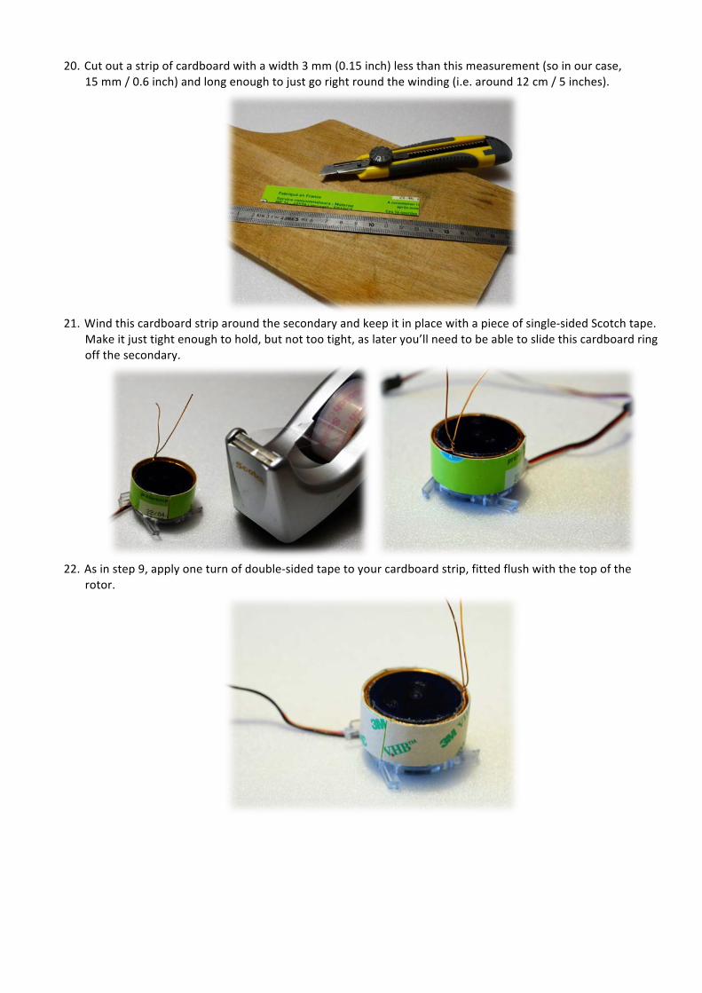
20. Cut out a strip of cardboard with a width 3 mm (0.15 inch) less than this measurement (so in our case,
15 mm / 0.6 inch) and long enough to just go right round the winding (i.e. around 12 cm / 5 inches).
21. Wind this cardboard strip around the secondary and keep it in place with a piece of single-‐sided Scotch tape.
Make it just tight enough to hold, but not too tight, as later you’ll need to be able to slide this cardboard ring off the secondary.
22. As in step 9, apply one turn of double-‐sided tape to your cardboard strip, fitted flush with the top of the
rotor.

23. The winding of the primary starts as in step 11, once again using 0.56 mm (24 AWG) enameled copper wire.
You’ll need a little bit greater length, so allow 15 m (46 feet) so as to avoid being short. The direction of the winding with respect to the secondary is unimportant, you can use whichever direction you prefer. Start winding nice and regularly near the top edge of the strip of cardboard, proceeding towards the bottom edge to produce around 26 closely-‐packed turns.
24. As in step 22, next apply a strip of double-‐sided tape over this first layer, then continue winding in the same
direction, but this time from bottom to top, to form the second layer of 25 turns.
25. When you get back to the start position, bend your wire back on itself for about 5 cm (2 inches). This is going
to form the transformer center tap.

26. Still smiling, let’s now wind the third layer, towards the bottom (around 26 turns), then let’s add a layer of
double-‐sided tape before winding the final layer upwards (around 25 turns).
27. Hang in there, it’s almost over! Cut the wire off at about 5 cm (2 inches) from the end of the last turn. A few
drops of cyanoacrylate glue will hold the winding in place, especially that wayward last turn. To keep them in place, twist the input lead to the first layer and the output lead from the final layer together for two or three turns. So you should now have two single wires from the two ends of the primary and a loop for the transformer center tap.
28. Once the glue is well set, you can easily slide the primary off the secondary.

29. All that’s left for you to do now is carefully remove the strip of cardboard and the first strip of double-‐sided
tape, which no longer serve any purpose. You will now be able to hold the inner layer in place with a few spots of glue.
30. The motor/secondary assembly can now be inserted into the base unit. It will be glued using a few drops of
epoxy adhesive on the four legs. Connect up the two motor supply wires to the corresponding solder pads (J6), with the positive pole to L4 and the negative to Q8.
31. The transformer primary will then be glued to the board on the other side, around the motor. Before
finalizing the epoxy gluing, first check that the motor turns freely without rubbing. 32. The three transformer connections will be connected to J4, with the center-‐tap soldered to the center pin of
the header. Tip: to remove the enamel from your copper wire, no need to scrape – a big blob of solder on the tip of your iron in contact with the wire for a few seconds will soon burn off the insulation, leaving the copper bare.

33. The final step in the assembly is crucial, and consists in gluing the propeller onto the motor, inserting the
spacers provided on the PCB panel. The stability of the propeller’s rotation is going to depend on how accurately it is centered. Line up the center of the rotor through the hole drilled in the middle of the propeller, then keep it perfectly centered while the epoxy adhesive dries.
34. Then connect the two secondary wires to J1. The polarity is unimportant. 35. Finally, one last tip: if balancing proves necessary when you start it turning, you can correct the imbalance by
adding solder to the pads located at the ends of the blades.