1:20 a3 ~1363 s235jr p0 20.1600.006.1.00
TRANSCRIPT

ISO 13715 - 0,5
1500
1100
177 2650
1680
36x 13
305
305
1610
AA
S1
S2S3
S4S9
3000 ~3566 ~3742
100
100
16
00
100
60
A-A
V=6 m3 S2
S3
pipe DN50
DESCRIPTION:S1 - Manway DN600S2 - Filling socket DN50 + overfilling valve (Self Climat) + flange DN50 PN16S3 - Suction socket DN50 + muff DN50 + pipe DN50S4 - Muff 2" (DN50) + PE plug DN50S9 - Leakage detection system socket DN25 for SGB DL 280
Tabela rewizji / Revision tableRewizja Revision
Imię i Nazwisko Name
Data Date
Podpis Signaure
Zakres zmian Scope of modyfication
Podpis / Signature
20.1600.006.1.00.0430
Krawędzie / Edges
Z:\[001] PDM\2. ZBIORNIKI\1. BEZCIŚNIENIOWE\2. ZBIORNIKI POZIOME PODZIEMNE DWUPŁASZCZOWE\Ø1600\20.1600.006.1.00.0430_Z701\
EN ISO 13920:1996 C/G
Norma przedmiotowaObjective standard
RewizjaRevision
Uwagi / Remarks:
DIN 6608
Rysunek jest własnością EKONSTAL- nie może być zmieniany, powielany ani transmitowany bez naszej autoryzacji.This drawing is EKONSTAL property- it can be neither copied nor transmitted without our autorization.
Rzutow./ Projection
P0
SprawdziłChecked
Tolerancje warsztatoweWorkshop tolerances
~1363
SkalaScale
Nazwa / Title
ArkuszSheet
1/1
Oś zbiornika
Format
Data / Date
Materiał / Material
Zbiornik podziemny dwupłaszczowy 1600mm V=6m3
S235JR
Nr rysunku / Drawing number
PN-EN ISO 2768-m
Indeks:
Tolerancje spawaniaWelding tolerances
Norma materiałowaMaterial standard
Kołnierz / Flange
Underground doublwall tank 1600mm V=6m3EKONSTAL Sp. z o.o. Sp. k.ul. Słoneczna 3088-230 Piotrków Kujawski, Polandtel.: +48 54 265-49-11faks: +48 54 265-49-12www.ekonstal.pl
ZatwierdziłApproved
KonstruowałDesigned
EN 10025
A3
-
1:20
Masa / Weihgt [kg]
Nazwisko / Name
Tank axis
D
E
F
C
1 2 3 4
B
A
321 5
C
D
4 6 7 8
A
B
SOLIDWORKS6 75
E
F
ISO 13715 - 0,5
3302 4000
770
36x 13
1000
1680
16
10
AA
S1
S2S3
S4
S4 S5S9
S9
S1
pipe DN50
100
50
24
00
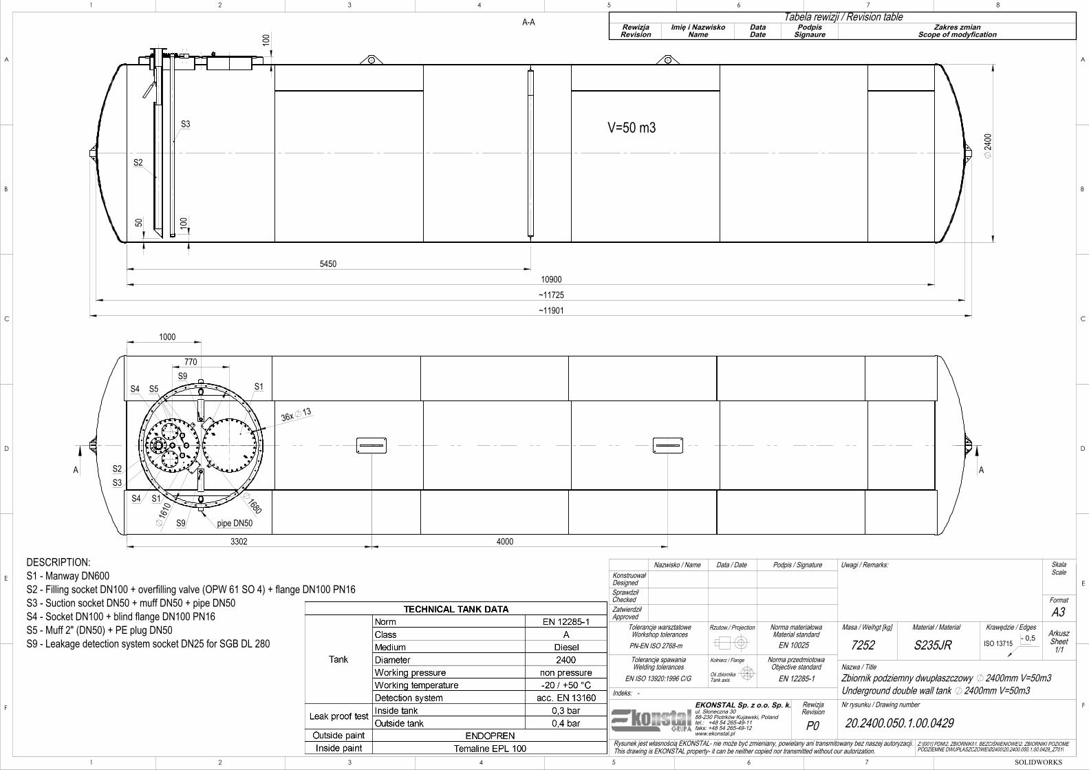
5450 10900
~11725 ~11901
100
A-A
V=50 m3
S2
S3
DESCRIPTION:S1 - Manway DN600S2 - Filling socket DN100 + overfilling valve (OPW 61 SO 4) + flange DN100 PN16S3 - Suction socket DN50 + muff DN50 + pipe DN50S4 - Socket DN100 + blind flange DN100 PN16S5 - Muff 2" (DN50) + PE plug DN50S9 - Leakage detection system socket DN25 for SGB DL 280
Tabela rewizji / Revision tableRewizja Revision
Imię i Nazwisko Name
Data Date
Podpis Signaure
Zakres zmian Scope of modyfication
Podpis / Signature
20.2400.050.1.00.0429
Krawędzie / Edges
Z:\[001] PDM\2. ZBIORNIKI\1. BEZCIŚNIENIOWE\2. ZBIORNIKI POZIOME PODZIEMNE DWUPŁASZCZOWE\Ø2400\20.2400.050.1.00.0429_Z701\
EN ISO 13920:1996 C/G
Norma przedmiotowaObjective standard
RewizjaRevision
Uwagi / Remarks:
EN 12285-1
Rysunek jest własnością EKONSTAL- nie może być zmieniany, powielany ani transmitowany bez naszej autoryzacji.This drawing is EKONSTAL property- it can be neither copied nor transmitted without our autorization.
Rzutow./ Projection
P0
SprawdziłChecked
Tolerancje warsztatoweWorkshop tolerances
7252
SkalaScale
Nazwa / Title
ArkuszSheet
1/1
Oś zbiornika
Format
Data / Date
Materiał / Material
Zbiornik podziemny dwupłaszczowy 2400mm V=50m3
S235JR
Nr rysunku / Drawing number
PN-EN ISO 2768-m
Indeks:
Tolerancje spawaniaWelding tolerances
Norma materiałowaMaterial standard
Kołnierz / Flange
Underground double wall tank 2400mm V=50m3EKONSTAL Sp. z o.o. Sp. k.ul. Słoneczna 3088-230 Piotrków Kujawski, Polandtel.: +48 54 265-49-11faks: +48 54 265-49-12www.ekonstal.pl
ZatwierdziłApproved
KonstruowałDesigned
EN 10025
A3
-
1:35
Masa / Weihgt [kg]
Nazwisko / Name
Tank axis
D
E
F
C
1 2 3 4
B
A
321 5
C
D
4 6 7 8
A
B
SOLIDWORKS6 75
E
F

ISO 13715 - 0,5
700
1050
2370
179 2660
50 50
24x13
350
350
959
AA
S1 S1
S2S2
S3S3
S4 S4
S9
1350
3000 ~3566 ~3742
100
100
16
00
1650
1015
100
60
A-A
"A"V=3 m3
"B"V=3 m3
S2S2
S3 S3
Pipe DN50
DESCRIPTION:S1 - Manway DN600S2 - Filling socket DN50 + overfilling valve (Self Climat) + flange DN50 PN16S3 - Suction socket DN50 + muff DN50 + pipe DN50S4 - Muff 2" (DN50) + PE plug DN50S9 - Leakage detection system socket DN25 for SGB DL 280
Tabela rewizji / Revision tableRewizja Revision
Imię i Nazwisko Name
Data Date
Podpis Signaure
Zakres zmian Scope of modyfication
Podpis / Signature
20.1600.006.2.00.0431
Krawędzie / Edges
Z:\[001] PDM\2. ZBIORNIKI\1. BEZCIŚNIENIOWE\2. ZBIORNIKI POZIOME PODZIEMNE DWUPŁASZCZOWE\Ø1600\20.1600.006.2.00.0431_Z701\
EN ISO 13920:1996 C/G
Norma przedmiotowaObjective standard
RewizjaRevision
Uwagi / Remarks:
DIN 6608
Rysunek jest własnością EKONSTAL- nie może być zmieniany, powielany ani transmitowany bez naszej autoryzacji.This drawing is EKONSTAL property- it can be neither copied nor transmitted without our autorization.
Rzutow./ Projection
P0
SprawdziłChecked
Tolerancje warsztatoweWorkshop tolerances
~1527
SkalaScale
Nazwa / Title
ArkuszSheet
1/1
Oś zbiornika
Format
Data / Date
Materiał / Material
Zbiornik podziemny dwupłaszczowy 1600mm V=6m3
S235JR
Nr rysunku / Drawing number
PN-EN ISO 2768-m
Indeks:
Tolerancje spawaniaWelding tolerances
Norma materiałowaMaterial standard
Kołnierz / Flange
Underground doublwall tank 1600mm V=6m3EKONSTAL Sp. z o.o. Sp. k.ul. Słoneczna 3088-230 Piotrków Kujawski, Polandtel.: +48 54 265-49-11faks: +48 54 265-49-12www.ekonstal.pl
ZatwierdziłApproved
KonstruowałDesigned
EN 10025
A3
-
1:20
Masa / Weihgt [kg]
Nazwisko / Name
Tank axis
D
E
F
C
1 2 3 4
B
A
321 5
C
D
4 6 7 8
A
B
SOLIDWORKS6 75
E
F
To enable continuous improvement of our products, the designs and specifications are subject to change without notice.Order against product code only.
© COPYRIGHT
ProductDescription:
Category:Notes:
Drawing No:
Date: Revisions:
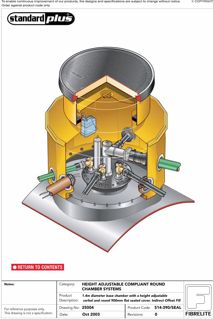
1.4m diameter base chamber with a height adjustable corbel and round 900mm flat sealed cover. Indirect Offset Fill
HEIGHT ADJUSTABLE COMPLIANT ROUNDCHAMBER SYSTEMS
25004 S14-390/SEALProduct Code
Oct 2003 0For reference purposes only.This drawing is not a specification.

To enable continuous improvement of our products, the designs and specifications are subject to change without notice.Order against product code only.
© COPYRIGHT
ProductDescription:
Category:Notes:
Drawing No:
Date: Revisions:
1.4m diameter base chamber with a height adjustable corbel and round 900mm flat sealed cover. Indirect Offset Fill
HEIGHT ADJUSTABLE COMPLIANT ROUNDCHAMBER SYSTEMS
2 S14-390/SEALProduct Code
Nov 2003 0For reference purposes only.This drawing is not a specification.
BS EN 1241994PAS 261998
MODELFL90CLASSC250
FL90 COVER
FL90 FRAME
SKIRT
INTERNAL LID
CORBEL
BOTTLE HOLDER
SPOUT
HANGER
FOAM BLOCK
S14 CHAMBER
CONDENSATION BOTTLE
SELF LEVELLINGADHESIVE SEALANT

To enable continuous improvement of our products, the designs and specifications are subject to change without notice.Order against product code only.
© COPYRIGHT
ProductDescription:
Category:Notes:
Drawing No:
Date: Revisions:
1.4m diameter base chamber with a height adjustable corbel and round 900mm flat sealed cover. Indirect offset Fill
HEIGHT ADJUSTABLE COMPLIANT ROUNDCHAMBER SYSTEMS
3 S14-390/SEALProduct Code
Nov 2003 0For reference purposes only.This drawing is not a specification.
300mm5 - 10mm
"A"
500mm
OUTER EDGE "A" OF FRAME SET 5 - 10MM ABOVE GENERAL FORECOURT AREA WITHCONCRETE RAMPED AWAY OVER 300MM.
VERY IMPORTANT
Self LevellingAdhesive Sealant
TARMACADAM
SETTS
TARMACADAM CONCRETE PEA GRAVEL SAND
Minimum200mm
Maximum350mm
CONCRETE
TYPICAL INSTALLATION
ALTERNATIVE INSTALLATION ADVICE
Minimum200mmMaximum350mm
300
500
25SETTS
130
150
A
Minimum200mmMaximum350mm
3005
5
TARMACADAM (THICKNESS AS SPECIFIED)
500
25
A
SKIRT
CORBEL
S14 CHAMBER
FL90 FRAME
FL90 COVER

To enable continuous improvement of our products, the designs and specifications are subject to change without notice.Order against product code only.
© COPYRIGHT
ProductDescription:
Category:Notes:
Drawing No:
Date: Revisions:
1.4m diameter base chamber with a height adjustable corbel and round 900mm flat sealed cover. Indirect offset Fill
HEIGHT ADJUSTABLE COMPLIANT ROUNDCHAMBER SYSTEMS
4 S14-390/SEALProduct Code
Nov 2003 0For reference purposes only.This drawing is not a specification.
ID 1100mm
12m
m35
0mm
320m
m
ID 848mm
1344mm A/F
ID 1320mm A/F
170m
m
700m
m
1107
Min
1357
Max
645
Max
395
Min 30
0 M
ax20
0 M
in
150 Max0 Min
25
INSTALLATION HANGER
GUIDE
Maximum Trim Point
OFFSET FILL APPLICATION
24 No. 13mm Holes
4
PCD 1145mm
PCD 1145mm

1
S17-3100 INSTALLATION INSTRUCTIONS
40FC SealantTubes (x 7)
FL100 FRAME
FL100 SKIRT
INTERNAL LID
S17 CORBEL
HANGER (x 4)
FOAM BLOCK (x 4)
S17 CHAMBER
GASKET
CONDENSATION BOTTLE
BOTTLE CARRIER
BOTTLE SPOUT
BS EN 1241994PAS 261998
MODELFL90CLASSC250
FL100 COVER
ISSUE 28/10/2013
Tank Sump Systems

2
S17-3100 INSTALLATION INSTRUCTIONS
12422
20
18
16
14
12
10
8
64 2 23
21
19
17
15
13
11
9
7
53
1
2
3
3
Clean the tank connection flange and ensure it is free of all grit etc. Check for flatness and deformation as this can cause the sump to become distorted or fail to seal. If in doubt contact our technical department (01756 799773).
Remove protective cover from base of chamber and position chamber onto tank flange, aligning the holes. Ensure the seal on the base of chamber is not damaged and is free from grit etc.
Starting with any bolt tighten to 7Nm/5lbfft torque. Move to the bolt positioned at 180° and tighten to 7Nm/5lbffttorque. Move 180° plus one bolt pitch and tighten to 7Nm/5lbfft of torque. Repeat until all bolts are tightened to 7Nm/5lbfft torque. Now repeat the procedure tightening all bolts to 13.5Nm/10lbfft torque.
Note: The seal will initially relax and it is an advantage if each bolt is tighten to 13.5Nm/10lbfft torque after a period of 24 to 48 hours after initial assembly.
24 No. holes shown in illustration
Fit a bolt and washer into each of the 36 holes (use only those supplied). Fit a washer and nut to each of the bolts. Tighten each bolt to 13.5Nm/10lbft torque, employing the following method, to avoid distortion of chamber.
7Nm/5lbft
13.5Nm/10lbft
( Sump Installation )

3
S17-3100 INSTALLATION INSTRUCTIONS
5
Drill(150mm dia hole saw)
Gloves Safety Goggles
Before installing pipework, fix a string line at ground level across the sump to check if material needs to be cut off the sump. If so, mark the sump with a line along the cut mark.Check to ensure you have the necessary minimum clearance required from the top of the sump to the centreline of the pipework/pipe entry kits.Standard Entry Kit = 145mm Large Entry Kit = 170mmFor shallow burials, it may be necessary to cut less material off the sump, and cut the remainder off the corbel and skirt to allow pipe entry boots to be fitted. PLAN THIS CAREFULLY.Refer to measurement chart.
Mark a centre point in the centre of a sump panel. Drill a pilot hole to ensure the hole saw can be positioned and used safely. 1 2
Face Mask
4WARNING Care must be taken to position the pipework and conduit so it exits the sump at 90˚ angle to the sump wall. Otherwise undue stress will be placed on the sump wall and entry boot, which may lead to leaks in the future.
Jigsaw+ Diamond tipped blades
Position pipeway at 90º angles to the sump wall. Ensure pipe entry boot is positioned away from the joints.
1 2
6
For larger holes (190mm) we recommend that the hole is marked and jigsaw is used to cut the hole. Firstly, drill a hole through the wall, so the jigsaw can be inserted and used easily and safely.(Fibreglass will blunt normal blades very quickly, we recommend diamond tipped blades or blades to cut ceramics).
7
NOTE : When backfilling ensure the pipework is not disturbed.WARNING : Do not backfill until the sump has been vacuum tested.
Ground Level
( Pipework and Entry Seal Kits )

4
S17-3100 INSTALLATION INSTRUCTIONS
OUTSIDECLAMPINGRING
INSIDEFLANGERING
PIPE SLEEVEPSB/125PSB/140PSB/160
S/STEEL STRAP
M6 SET SCREWS
NITRILEFLANGEGASKET
CHAMBERWALL
PIPE SLEEVEPSB/50, PSB/63& PDB/63-75
PIPE SLEEVEPSB/75, PSB/90& PSB/110
INSIDE OFCHAMBER
INSIDE OFCHAMBER
PIPE ENTRY KITS: -PSB/125, PSB/140 & PSB/160
PIPE ENTRY KITS: -PSB/50, PSB/63, PSB/63/VT, PSB/75PSB/90, PSB/110, PDB/63-75
STRAP
STRAPGASKET
PIPE SLEEVE
190
DIA
HO
LE
110m
m
STRAP
STRAPGASKET
PIPE SLEEVE
150
DIA
HO
LE
DRILL AND HOLE SAWATTACHMENT OR JIGSAW
PIPE SLEEVEPSB/63/VT
The exit position of the pipework through the chamber wall must be as close as possible to 90°. The pipe kit should be fitted so that the pipework is centrally positioned to the seal. When backfilling ensure that the pipework is not disturbed from this central position.
NB: Where appropriate, it is recommended that a drill piloted hole saw be used to cut the pipe/cable seal entry hole in the chamber.
Angles of flexible entry sleeves must not exceed 12° from centre line (24° inclusive angle).
NB: Straps/clips are to be tightened in accordance with the pipe manufacturers recommendation
( Pipework and Entry Seal Kits )

5
S17-3100 INSTALLATION INSTRUCTIONS
8 PCE/1 KITSRefer to pipe entry boot instructions on positioning of the hole.
Conduit must be installed at 90º angle to the side wall.
NB. Where appropriate, it is recommended that a drill piloted hole saw be used to cut the pipe/cable seal entry hole in the chamber.The exit position of the pipework through the chamber wall must be as close as possible to 90° and must not exceed 12º from centre line (24º inclusive angle). The pipe kit should be fitted so that the pipework is centrally positioned to the seal. When backfilling ensure that the pipework is not disturbed from this central position.
OUTSIDE CLAMPING RING
SEALING GLANDPCE/1
INSIDE FLANGE RING
PIPE SLEEVE 110mm O/D
S/STEEL STRAP
4 No M6 SET SCREWS
NITRILE FLANGE GASKET
CHAMBER WALL
100mmDUCTING
150
DIA
HO
LE
110m
m
STRAP
STRAP
GASKET
DUCTING PIPE SLEEVE
PSB/110 PIPEKIT
MAIN BODY PCE/1 SEALING GLAND(4 cables Ø9 - Ø20mm or 12 cables Ø5 - Ø8mm)
INSIDE OF CHAMBER
Threaded Hexagonal Nut (Qty. 4)
Standard Doughnut (Qty. 4) accommodates single cable Ø9mm to Ø20mm
Multiple Doughnut (Qty. 4) accommodates 3 cables Ø5mm to Ø8mm
Blind Insert (Qty. 5)
Main Body (Qty. 1)
Layer Rings
The PCE/1 sealing body is capable of sealing to ducts with an internal diameter ranging from 97 to 110mm.
The PSB/110 pipe seal kit is capable of sealing to ducts with a external diameter ranging from 99 to 116 mm.
( Conduit entry seal kit installation guide )
Firstly, determine the number and size of cables to be routed through the entry seal and fit the appropriate rubber doughnut (standard or mul-tiple) into the recess of the main body. For cables with an O/D greater than 9 mm the appropriate layer ring must be cut from the single hole rubber doughnut to accommodate the cable size. Ensuring there is a washer both sides of the rubber doughnut. Finger tighten the threaded hex-agonal nut onto the inserts. Pull the cables through the doughnut openings and fit the main body into the ducting. When in position lock the main body in place by tightening the M8 socket cap screw in the centre of the main body (6mm allen key). Expanding the main body bellows against the internal the diameter of the ducting to create a seal.
When the position of the cables is finalised tighten the threaded hexagonal nut until the cables are sealed in the doughnut openings(s). This is achieved when the cable CANNOT be moved inside the doughnut.
Any doughnut opening not used must be sealed off using the plastic blind insert.

6
S17-3100 INSTALLATION INSTRUCTIONS
9 After penetrations have been fitted, ensure all connections on the manway lid are sealed.Perform vacuum test. Refer to Vacuum test instructions.
Do not backfill around sump or cut material off the sump until the test has passed successfully.
( Sump Vacuum Test )

7
S17-3100 INSTALLATION INSTRUCTIONS
?10m
m
10 Fix string lines 10mm above grade level across the sump - across length and width of the tank farm to highlight any falls.
IMPORTANT
Refer to this measurement chart;
Measurement(clearance dimension)
Action
Max. 300mmMin. 225mm
No trimming required, corbel can be bonded onto the sump. Adjust frame height using hangers.
less than 225mm Option 1: If by trimming material (max of 100mm) from the corbel turret increases the ‘clearance dimension’ into the 300mm - 225mm range then material only needs to be trimmed from the corbel turret and skirt. Trim the skirt so that the overlap between the corbel turret and skirt is 90mm.
Option 2: If by trimming 100mm from the corbel turret does not increase the ‘clearance dimension’ into the 300mm - 225mm range then the remaining material must be removed from the sump. A maximum of 400mm can be removed from the sump. Trim the corbel and skirt as described above in option 1.
more than 300mm
The burial depth of the tank is greater than the maximum burial depth of the standard system. Contact Fibrelite:+ 44 (0) 1756 799 773
1512
MA
X89
7 M
IN
800
MA
X
140
2510
260
400
700
MA
X48
5 M
IN 30
0 M
AX
225
MIN
OV
ER
LAP
GRADE LEVELSTRING LINE90
12
11 Place the corbel onto the sump (only ‘dry fit’ the corbel do not bond at this stage). Check the measurement from the top of the corbel to the string line, which is set 10mm above the general grade level. Check all sides of the sump and select the largest and smallest measurement to take account of falls across the forecourt.
Largest & Smallestmeasurement
Clearance Dimension
10mm
( Achieving the correct height )

8
S17-3100 INSTALLATION INSTRUCTIONS
13 Before trimming the sump check pipe entry positions allow 50mm from top edge to be able to fit the corbel in position.If necessary cut a smaller amount off the sump height, then cut the remaining material from the corbel and skirt.
Important Note: Trim the corbel and skirt so that the clearance from the top of the frame to the top of the corbel falls in the range 300 to 225mm and that the overlap between the skirt and corbel is a minimum of 90 mm.
WARNING Do not trim sump until sump has been vacuum tested with pipework installed and completed.
50mmmin
< 140mmCORBEL
> 140mm
90mm
14 Ensure that you have a min overlap of 90mm between the skirt and corbel, to allow space to install the seal kit.
< 75mmSKIRT
> 75mm
( Achieving the Correct Height )

9
S17-3100 INSTALLATION INSTRUCTIONS
ACETONE
15
16
Abrade and wipe with a degreasing solvent the chamber or extension top edge/wall and the corbel groove.
Dry fit the corbel on the sump to ensure it fits - push corbel groove onto sump wall.If it does not fit, pipework may have distorted the sump wall shape.
17 Measure distance between opposite walls, this should be 1718mm. If less than this you will need to brace out the sump.
Using wooden batons (1718mm ±5mm long) with timber spreader plates (150 x 150) to spread the load, brace out the sump to the correct size.
Repeat this process on all walls to get the correct shape.
1718mm
1718mm
18 Apply 3 tubes of soudaflex 40FC sealant in the groove of the corbel. Sealant should fill 1/2 the groove.
19 Place the corbel on the sump using 2 people and push it into position.
( Bonding the Corbel )

10
S17-3100 INSTALLATION INSTRUCTIONS
20 Seal around the inside edge of the corbel joint from inside the sump. Smooth off the sealant with soapy water.
Use 1.5 tubes of soudaflex 40FC sealant.
21 Seal around the outside joint and smooth off sealant with soapy water.
Use 1.5 tubes of 40FC sealant.
Ensure all pipework and electrical entries have been completed before vacuum testing, this is a final test for all penetrations in the sump.
Warning: Test the corbel at a 0.6m depth setting only or irreparable damage may occur.
Refer to vacuum testing instructions for correct method.
( Performing Corbel Vacuum Test )
23
Wait a min of 12 hours before vac testing, preferably overnight to allow sealant to set before vacuum testing.
Do not disturb the sump during this time. 12hoursmin
22
( Bonding the Corbel )

11
S17-3100 INSTALLATION INSTRUCTIONS
24 Once the corbel test has been performed with a PASS result, the area around the sump can be carefully backfilled with peagravel or sand. Back-fill equally around the sump in layers to prevent damage or deformation.
25 Fix a string line 10mm above grade level across the sump, fix 4 hangers on the corbel top with base support facing out.
26 Put the skirt and frame on the hangers.
Locate the 4 foam blocks supplied between the skirt and corbel turret to centralise the skirt about the corbel. Failure to do this may result in the internal lid fouling.
27 Adjust knobs to set the frame to stringline level, adjust for fall in grade. Set the frame 10mm above grade level.
Grade Level
Grade Level
Grade Level
10mm
skirt
corbel
( Backfilling )
( Adjusting the Skirt & Frame to Grade Level )

12
S17-3100 INSTALLATION INSTRUCTIONS
28 Ensure the void between corbel and skirt is kept free from concrete and a depth of 90mm overlap minimum is maintained.
Ensure foam spacers are in position to locate the skirt centrally around the corbel.
29 Complete backfilling to appropriate level. Frame must be supported by a minimum depth of 200mm of concrete
Concrete ties must be inserted as close to the frame as possible. Minimum block of 500mm square around the frame. Joint must be tied as per diagram. Continuous pour preferred if possible.
CONCRETE PEA GRAVEL
VERY IMPORTANTThe underside of the framemust be adequatelysupported by concrete.
Expansion joint filledwith petrol resistantmastic.
Concrete reinforcedwith 2 layers of reinforcement mesh.
300mm5 - 10mm
"A"
500mm
OUTER EDGE "A" OF FRAME SET 5 - 10MM ABOVE GENERAL FORECOURT AREA WITHCONCRETE RAMPED AWAY OVER 300MM.
VERY IMPORTANT
Minimum200mm
Maximum350mm
CONCRETE
TYPICAL INSTALLATION
CORBEL
S17 CHAMBER
FL100 FRAME &COVER
Joint tied with600mm long x 12mmdowel at 600mm c/c.Half bonded
90mm
( Concreting )

13
S17-3100 INSTALLATION INSTRUCTIONS
30 After minimum concrete cure time, hangers can be removed. Loosen the ‘T’ knob, push down on the rod, turn the rod through 90˚ and pull rod up to remove.
Complete other third party equipment installation inside the sump.
( Installation of Corbel / Skirt Sealant )
33 Insert sand in the void to a depth of 50mm from top of corbel. Compact the sand.
34 Drain and bottle should be positioned away from pipe risers and stp. The drain must be installed at the created low point to do this. Compact the sand in a way to create a low point 10-15mm lower than the surrounding sand.
31
Ensure void is free of concrete to a depth of 90mm (120mm on a high water table installation).
32
1
2
Abrade surface of corbel and skirt with sand paper.
Use acetone to clean surface of corbel and skirt. Ensure surfaces and channel are dry and free from dirt and grease.
DEGREASE
50mm min. 90mm overlap
sand - 40mm
Lowpoint
Install Drain and bottle here
( Concreting )

14
S17-3100 INSTALLATION INSTRUCTIONS
sand
Cold poursealant
( Installation of Corbel / Skirt Sealant )
35 Mixing and Application
Application Temperature +5 to +45˚C
(Do not apply at temperatures below +4 degrees ˚C)
Pot Life 45 minutes @ 25˚C Cure Times @ 25˚C Tack Free 2 1/2hrs Full Cure 2 days
Using a suitable container stir the contents of Pack B and add the entire contents to Pack A to give a combined content of 4.5Ltrs. Ensure white sediment from can B is put into can A before mixing. Stir for a full 5 minutes using a slow speed electric drill (400 -500 rpm) with a mixer paddle until a completely homogeneous mix is obtained. Take care to avoid including excess air. Mixing is made easier if the Pack B is added and mixed in two stages.
WARNING If white sediment is not added to mixture, or contents are not mixed thoroughly using an electric mixer - the sealant will not set and will need replacing
36
37
Fitting Bottle Hanger
When the sealant is tack free the bottle hanger may be fitted. Ensure that when the bottle hanger is fitted the water will drain down the spout.
38
Mark out the position of the two holes to be drilled 24mm down from the top edge of the Corbel and 60mm cross centre. Drill the two Ø7mm holes into the Corbel walls.
Also mark out the position of the drain hole to align with the hole in the drain spout and drill 1 No. Ø16mm through the corbel wall.
1 2
3
A+B = 4.5L
5 min.
30mm
Rubber gasket
24mm
Ø7mm
24mm
60mm
Ø16mm
AA
B
4
1 set of cans A+B will seal 2 sumps. Decant mixture from can A into can B to have more control when puring the mixture into the void, onto the sand base. Avoid spilling the contents to ensure a clean finish on the side walls of corbel and skirt. The sealant shall be poured to level 30mm below the top edge of the Corbel (the amount of sealant required is dependant on the height of the system but should be between 1.5 and 1.7 Litres).

15
S17-3100 INSTALLATION INSTRUCTIONS
41 Test completed system.
Warning: Test the corbel at a 0.6m depth settingonly or irreparable damage may occur.
When testing at this stage the drain hole which isdrilled in the corbel turret must be blanked off toachieve a test.
40 Do not install the internal lid until the sealant has set. Wait overnight.
12hours
39 Ensure the rubber gasket is fitted to the mating surface of the bottle hanger. Secure the Bottle Hanger to the Corbel wall with 2 No. M6 x 15 Dome Head Screws and Washers.
Locate the Condensation Bottle into the Bottle carrier and suspend the Bottle Carrier from the Bottle Hanger.
( Concreting )