(12) united states patent us 7,125,540 bl (45) date of patent
TRANSCRIPT
US007125540B1
(12) United States Patent Wegeng et al.
(io) Patent No.: (45) Date of Patent:
US 7,125,540 Bl Oct. 24, 2006
(54) MICROSYSTEM PROCESS NETWORKS
(75) Inventors: Robert S. Wegeng, Richland, WA (US); Ward E. TeGrotenhuis, Kennewick, WA (US); Greg A. Whyatt, West Richland, WA (US)
(73) Assignee: Battelle Memorial Institute, Richland, WA (US)
( * ) Notice: Subject to any disclaimer, the term of this patent is extended or adjusted under 35 U.S.C. 154(b) by 1148 days.
(21) Appl. No.: 09/588,999
(22) Filed: Jun. 6, 2000
(51) Int. Cl.
C01B 3/24 (2006.01) B01J10/00 (2006.01) B01J 8/04 (2006.01)
(52) U.S. Cl 423/650; 422/193; 422/195 (58) Field of Classification Search 423/650;
252/373; 422/188,193,195,200; 165/166, 165/167, 170
See application file for complete search history.
(56) References Cited
U.S. PATENT DOCUMENTS
3,608,610 A 9/1971 Greatorex et al 159/13 3,912,003 A 10/1975 Schrade 165/165 3,961,917 A 6/1976 Benedict et al 55/16 4,373,579 A 2/1983 Jernqvist et al 165/167 4,386,505 A 6/1983 Little 62/514 4,392,362 A 7/1983 Little 62/514 4.401.155 A 8/1983 Royal et al 165/166 4,516,632 A 5/1985 Swift et al 165/167 4,665,975 A 5/1987 Johnston 62/497 4,763,488 A 8/1988 Johnston 62/497 4,795,618 A 1/1989 Laumen 422/202 5,209,906 A 5/1993 Watkins et al 422/200 5,270,127 A 12/1993 Koga et al 429/17 5,324,452 A 6/1994 Allam et al 252/373 5.419.156 A 5/1995 Sywulka 62/476
5,426,442 5,534,328 5,611,214 5,811,062 5,858,314 5,861,137 5,901,037 6,036,927 6,100,436 6,118,038 6,143,943 6,159,358 6,168,765 6,180,846 6,190,624 6,193,501 6,200,536
A A A A A A A A A A A A Bl Bl Bl Bl Bl
6/1995 7/1996 3/1997 9/1998 1/1999 1/1999 5/1999 3/2000 8/2000 9/2000
11/2000 12/2000 1/2001 1/2001 2/2001 2/2001 3/2001
Haas 343/778 Ashmead et al 428/166 Wegeng et al 62/498 Wegeng et al 422/129 Hsuet al 422/211 Edlund 423/652 Hamilton et al 361/699 Chatterjee et al 422/211 Wiede, Jr 422/198 Lankton et al 585/922 Oroskar et al 585/654 Mulvaney et al 208/46 Romantier et al 422/200 Dandekar et al 585/443 Romantier 422/200 Maseletal 431/170 Tonkovich et al 422/177
(Continued)
FOREIGN PATENT DOCUMENTS
DE 3926466 Al 2/1991
(Continued)
OTHER PUBLICATIONS
Merriam-Webster's Collegiate Dictionary, 10 Edition, 1997, p. 317.*
(Continued)
Primary Examiner—Colleen P. Cooke (74) Attorney, Agent, or Firm—Frank Rosenberg
(57) ABSTRACT
Various aspects and applications of microsystem process networks are described. The design of many types of microsystems can be improved by ortho-cascading mass, heat, or other unit process operations. Microsystems having exer-getically efficient microchannel heat exchangers are also described. Detailed descriptions of numerous design features in microcomponent systems are also provided.
64 Claims, 28 Drawing Sheets (1 of 28 Drawing Sheet(s) Filed in Color)
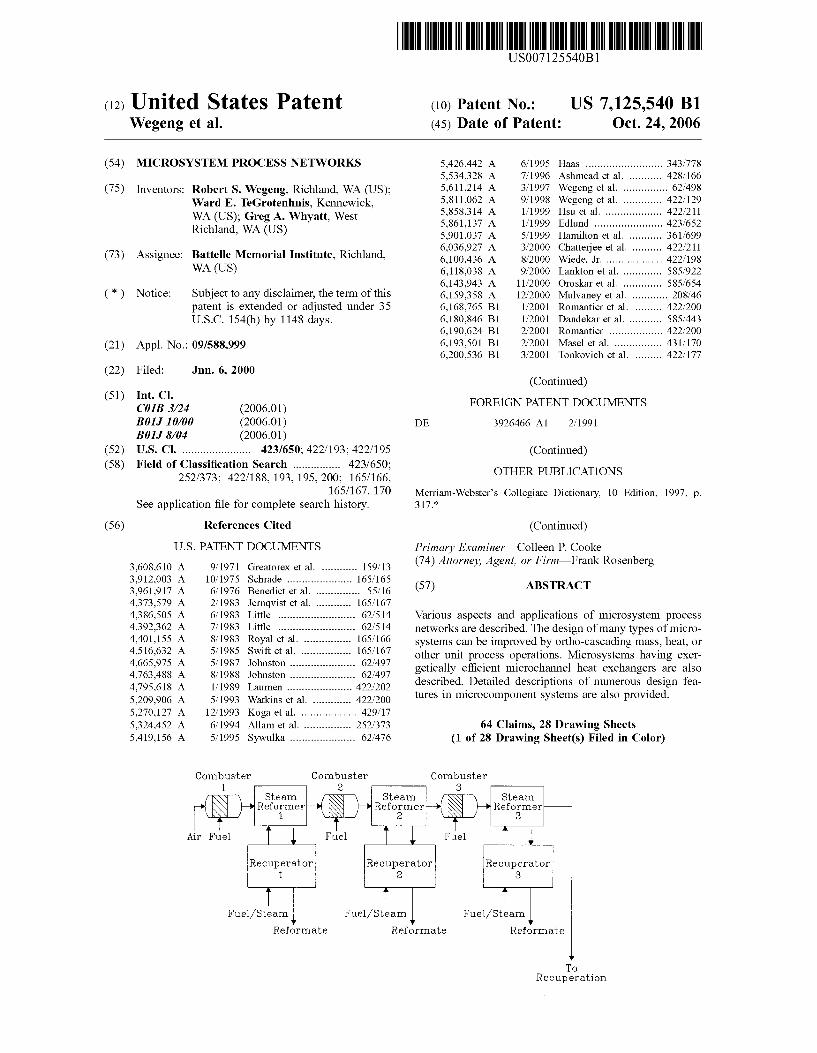
Combuster 1
Air Fuel
Combuster 2
rj\xi—\ Steam /TSSS] \ S t eam /"rcjS \ Steam r-*\ \N r~* Reformer—W S$$ }—+ Reformer—W >$N I—•Reformer-
\KV^ / 1 VK I / 2 USSLJ 3 T x i T * i T
Fuel
Recuperator 1
Fuel /Steam
Combuster 3
Fuel
Fue l /S t eam
Reformate Reformate
Fue l /S team
To Recupera t ion

US 7,125,540 Bl Page 2
U.S. PATENT DOCUMENTS
6,228,341 Bl 5/2001 Hebert 423/352 6,274,101 Bl 8/2001 Sechrist 422/198 6,537,506 Bl 3/2003 Schwalbe et al 422/130 6,616,909 Bl 9/2003 Tonkovich et al 423/648.1
FOREIGN PATENT DOCUMENTS
DE 19825102 Al 12/1999 DE 19841993 Al 3/2000 EP 0543132 Al 5/1993 EP 0810682 A2 12/1997 EP 0885653 A2 12/1998 WO WO 97/39490 10/1997 8/24 WO WO 98/58743 12/1998 WO WO 99/00186 1/1999 WO WO 99/61147 12/1999
OTHER PUBLICATIONS
L Tonkovich et al., "Catalyst, Method of Making, and Reactions Using the Catalyst", (E-1666A CIP Application, U.S. Appl. No.: 09/492.950). p. 1-22. 2000. RS Wegeng et al., "Method and Apparatus For Obtainint Enhanced Production Rate ofTherman Chemical Reactions", (E-1666B CIP Application, U.S. Appl. No.: 09/492,246), p. 1-42, 2000. RA Gaggioli et al., "Thermodynamics: Second Law Analysis", p. 111-127. 1980. R Buxbaum, "Membrane Reactors, Fundemental And Commercial Advantages, E.G. For Methanol Reforming", p. 1-6. 2000.
EAGillis, "Fuel Cells for Electric Utilities", p. 88-93, 1980. I Hermann et al., "Microreaction Technology in Fuel Processing for Fuel Cell", p. 447-453. 2000. "Printed Circuit Reactor (PCR)", www.heatric.com, p. 1-3. 2000. AY Tonkovich et al., "MicroChannel Chemical Reactors for Fuel Processing", p. 186-195. 1998. RS Wegeng et al., "MicroChannel Fuel Processing Components", p. 1-18. 1999. AY Tonkovich et al., "MicroChannel Chemical Reactors for Fuel Processing Applications. II Compact Fuel Vaporization", p. 1-9. 2000. AM Adris et al., "On The Reported Attempts to Radically Improve The Performance of The Steam Methane Reforming Reactor", p. 177-186. 1996. AJ Franz et al., "New Operating Regimes and Applications Feasible with Microreactors", p. 33-38. 1997. Szargut et al., "Exergy Analysis of Thermal, Chemical, and Metallurgical Processes", p. 140-142, 164-166, 250-256. 1988. A Cybulski et al., "Structured Catalysis and Reactors", p. 438-500. 1998. R Smith et al., "Separation Technology: The Next Ten Years", p. 161-174. 1995-P. "Second law analysis of a plate heat exchanger with an axial dispersive wave," Das et al., Cryogenics, 38, pp. 791-798 (1998). PCT Search Report, mailed May 31, 2002, PCT/US 01/17631. "Technology And Applications of Microengineered Reactors," Gavriilidis et al., Trans IchemE, 80, Part A, Jan. 2002, pp. 3-30.
* cited by examiner

U.S. Patent Oct. 24, 2006 Sheet 1 of 28 US 7,125,540 Bl
o
Ste
am
Ref
orm
er
3
' k
t w
4 R
ecu
per
ato
r 3
p.
CD
a r O
4 is \
o ft
o CD
^

U.S. Patent Oct. 24, 2006 Sheet 2 of 28 US 7,125,540 Bl
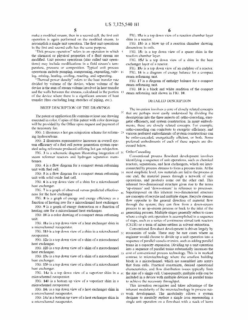
800 850 900 950 1000 Comb. Gas Inlet Temp (C)
1050
4 Reactor Train 2 Reactor Train No reinjection
Fig. 2

U.S. Patent Oct. 24, 2006 Sheet 3 of 28 US 7,125,540 Bl
0^
cti
-4-J
m
CD
u o
a cC CD
-t-J CO
CD

U.S. Patent Oct. 24, 2006 Sheet 4 of 28 US 7,125,540 B l
C o m p a c t Mic roChanne l S y n g a s P r o d u c t i o n Un i t
C o m b u s t e r — *
S t e a m R e f o r m e r
R e f o r m F u e l M i x t u r e
Comb , g a s
R e c u p 1 —ar
R e f o r m a t e
H 2 + F u e l ( g )
Air
Fue l (g ) C o m b , g a s
R e c u p 1 —*—
F u e l V a p o r i z e r
R e f o r m a t e
S t e a m Water
V a p o r i z e r
Liquid F u e l
Wa te r P r e h e a t e r
— r R e f o r m a t e
L.
H 2 0(1)
H 2 0(1) C o m b .
g a s
P r e h e a t e d Air
H,
Anode Waste
H e a t E x c h a n g e r
R e f o r m a t e R e f o r m .
Wate r Gas Shif t
Air
E x h a u s t - * G a s R e f o r m a t e
PROX
C O / C O 2
S e p a r a t i o n
CO.COg...
Anode F e e d
Fue l Cell
Fig. 4

U.S. Patent Oct. 24,2006 Sheet 5 of 28 US 7,125,540 B l
260
Solid Oxide Fuel Cell <-
1000 C Anode Waste
Anode Feed
Cathode Waste
240
Recuperator 1
Reformate
Steam Reformer/ Combuster
750C
Combustion Gas
230.
100 Watts Electricity
Cathode "270 Feed
Methane/
H20
02 Preheater : * ~
Recuperator 2
220 H20 Vaporizer
x
Combustion Gas
H n(liq)
CH4 * Vaporizer
210
H20 Vap/Liq
Separator To ISPP(?)
02 Vaporizer
H«0(liq)
CH4 (liq) 02 (liq)
Fig. 5
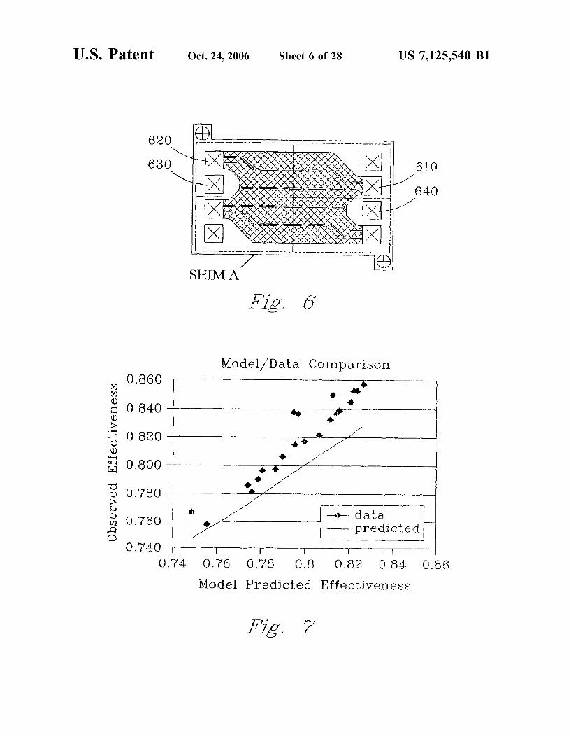
U.S. Patent Oct. 24, 2006 Sheet 6 of 28 US 7,125,540 Bl
0.740
SHIM A
Fig. 6
Mode l /Da ta C o m p a r i s o n
-«•— d a t a — p r e d i c t e d
0.74 0.76 0.78 0.8 0.82 0.84 0.86
Model P r e d i c t e d Effect iveness
Fig. 7

U.S. Patent Oct. 24, 2006 Sheet 7 of 28 US 7,125,540 Bl
Firs t and Second Law Efficiencies 100
u 0) o
90
80
w 70
60 0
- • • ^ • v # } n V*J • * • * • •
• Energy Efficiency • Exerget ic Efficiency
200 400 600 800 1000 Heat ing Rate (watts)
Fig. 8
o
-I—I
OT te:
Q
0)
iao cd
<u
140
120
100
80
60
40
20
0 0
E x e r g y D e s t r u c t i o n
JL n
200 400 600 800 Heating Rate (watts)
1000
Fig. 9

U.S. Patent Oct. 24, 2006 Sheet 8 of 28 US 7,125,540 B l
110
101
138
112 X
i ~ ~ - ^
; : 108 106
- ,«*a33
140
114
122
118
104
102
110
Fig. 10
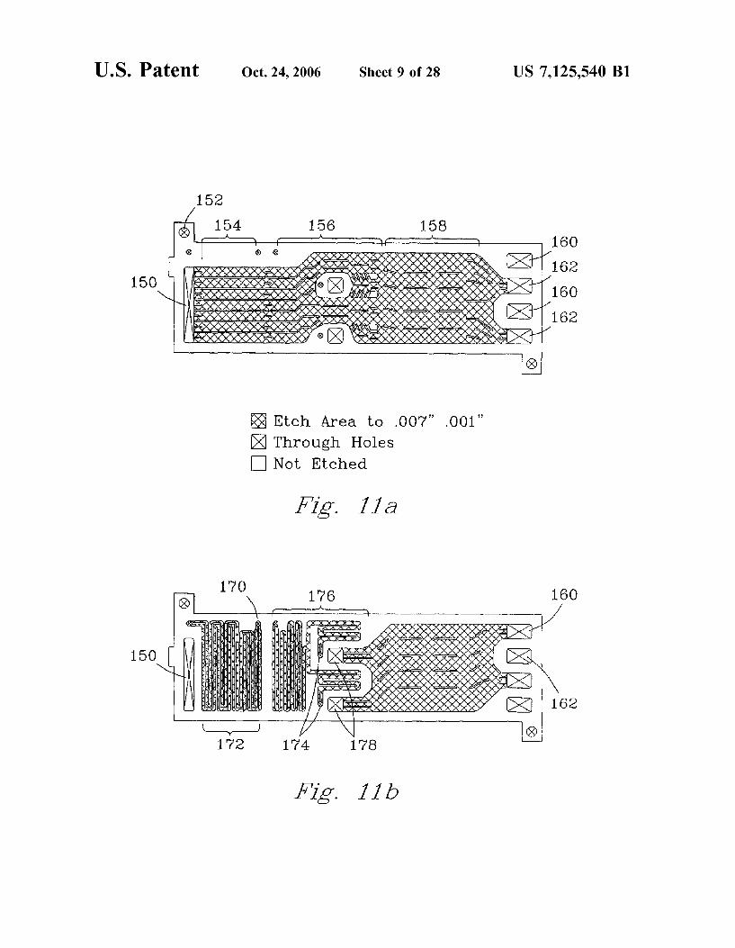
U.S . P a t e n t Oct. 24,2006 Sheet 9 of 28 US 7,125,540 Bl
150
Etch Area to .007" .001" ^ Through Holes • Not Etched
Fig. 11a
170 176
150 f
172 174 178
160
162
Fig. lib

U . S . P a t e n t Oct. 24,2006 Sheet 10 of 28 US 7,125,540 Bl
1000
\
'A" SHIM
1010 1010
Fig. 12a 1020
1040 1040
1030 1030
Fig. 12b "B" SHIM

U . S . P a t e n t Oct. 24,2006 Sheet l l of 28 US 7,125,540 Bl
Fig. 13a
®
Fig. 13b
U.S. Patent Oct. 24, 2006 Sheet 12 of 28 US 7,125,540 Bl
^ > ^
' v ^ ^ ^ ^ ^ ^ . / N ^ r N A A ^ ^
•Sp

U.S. Patent Oct. 24, 2006 Sheet 13 of 28 US 7,125,540 Bl

U.S. Patent Oct. 24, 2006 Sheet 14 of 28 US 7,125,540 Bl
300
304
314 308
310
304
306
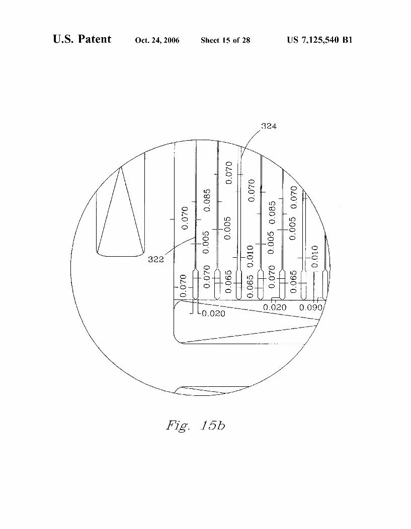
314 308 302 312
Fig. 15a
U.S. Patent Oct. 24, 2006 Sheet 15 of 28 US 7,125,540 Bl
324
Fig. 15b

U.S. Patent Oct. 24, 2006 Sheet 16 of 28 US 7,125,540 Bl

U . S . P a t e n t Oct. 24,2006 Sheet 17 of 28 US 7,125,540 Bl
r ®
/
364
3 6 0 — •
J c
362
366 o
D C
N 368
Fig. 15e
U.S. Patent Oct. 24, 2006 Sheet 18 of 28 US 7,125,540 B l
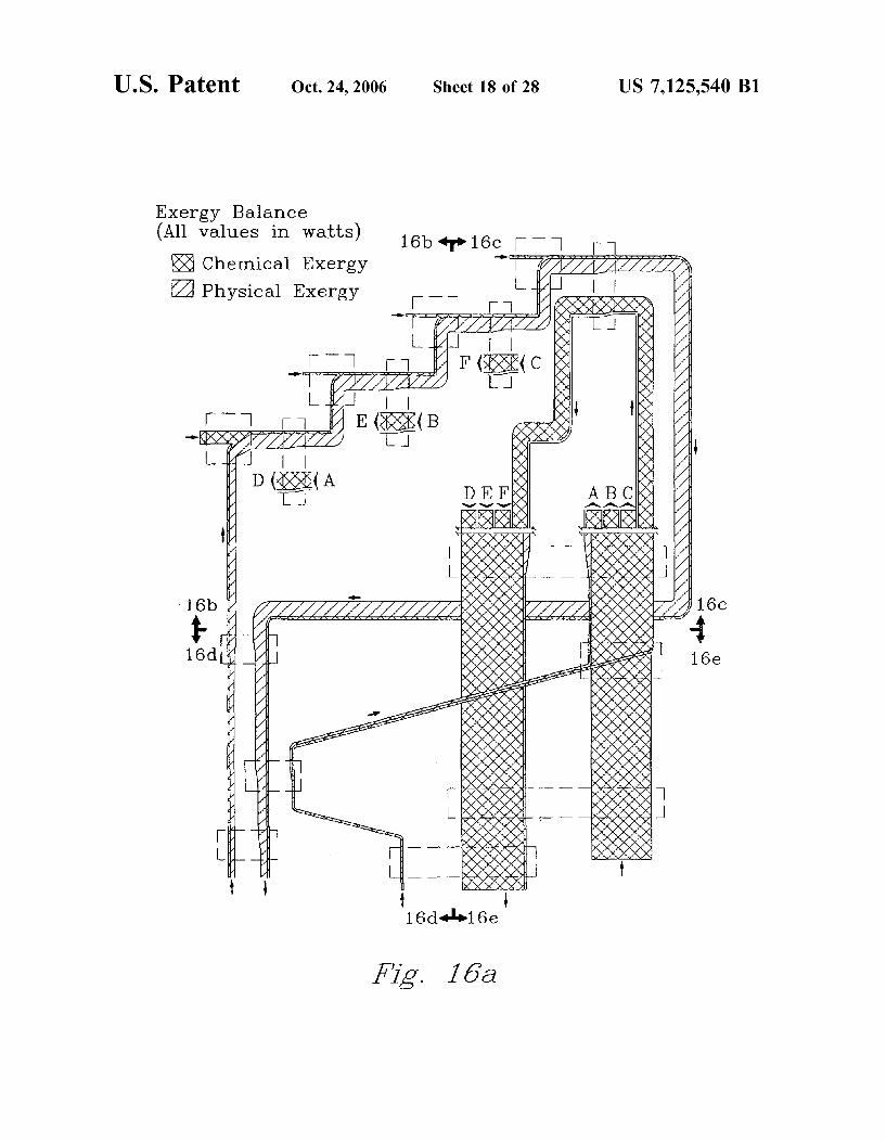
Exergy Balance (All va lues in wa t t s )
Chemical Exergy
Physical Exergy
16b 16c | 1
16b
Fig. 16a

U.S. Patent Oct. 24, 2006 Sheet 19 of 28 US 7,125,540 Bl
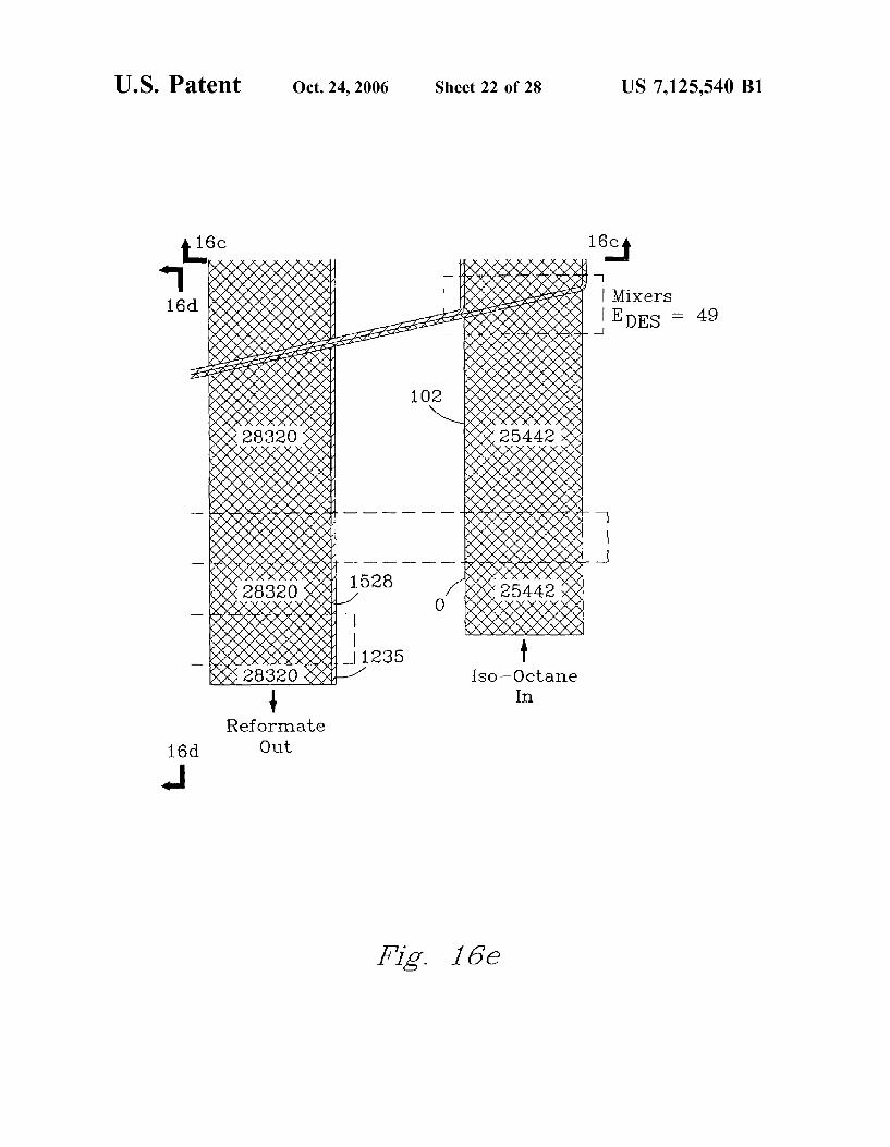
Exergy Balance (All values in wat ts )
15 1 Chemical Exergy
Physical Exergy
r 16c
Mixer— Combuster 3 EDES = 2 6 3
1110. r Fuel In-
Mixer—Combustor 2
1110 Fuel In
Mixer—Combustor 1 EDES = 1 6 0 0 589
I 16648 Fuel
In"*
Fig. 16b

U.S. Patent Oct. 24, 2006 Sheet 20 of 28 US 7,125,540 Bl
*1 16b
M i x e r - C o m b u s t o r 4 EDES = 2 3 8 695
1110 I 1 6903 L - _,
" " ^ v v v ^/vr y?* si y y, y^ ? ? O^TTT ? y y y y y y.
Fig. 16c

U.S. Patent Oct. 24, 2006 Sheet 21 of 28 US 7,125,540 Bl
ti< 6b 16hH —1 Combustion Gas
Recupera to rs
1397
417
Air f P r e h e a t e r s E D E S = 80 L
417 t 1 4 1 7 \
Air In Combust ion P roduc t s Out
1069
Water In 16e
L
Fig. 16d
U.S. Patent Oct. 24, 2006 Sheet 22 of 28 US 7,125,540 Bl
16c 16c,
16d
J
Mixers E D E S = 49
Iso—Octane In
Reformate Out
Fig. 16e

U.S. Patent Oct. 24, 2006 Sheet 23 of 28 US 7,125,540 B l
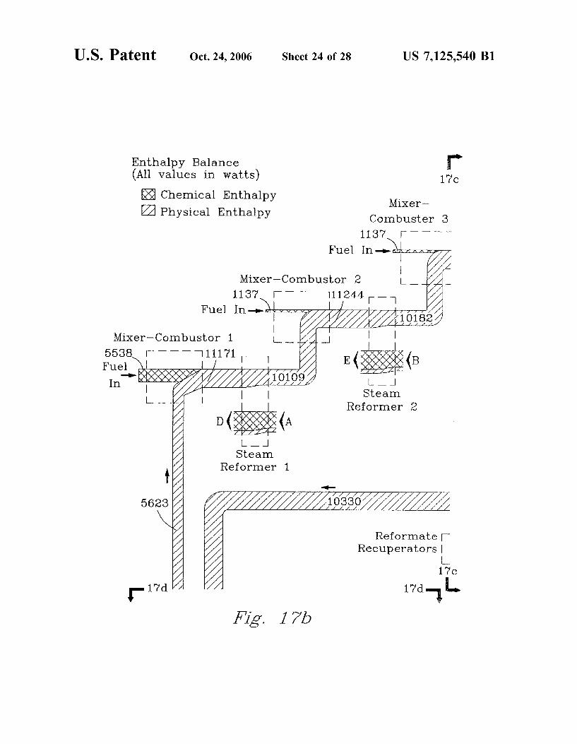
Entha lpy Balance (All va lues in wat t s )
RjRJi Chemical En tha lpy
Physical En tha lpy
17b 17c | 1
j " H , t r-i
^ ^ ^ ^ D E F / / / / /
/
17b /
M 17dLt
17d^Wl7e
Z7^. 7 7^
U.S. Patent Oct. 24, 2006 Sheet 24 of 28 US 7,125,540 B l
Enthalpy Balance (All values in watts)
Chemical Enthalpy Physical Enthalpy
17c
Mixer— Combuster 3
1137. r Fuel In.
Mixer—Combustor 1 i_ 5538. I 111171 Fuel
In"
Mixer-Combustor 2 1137
Fuel In—»>«fe"^-
I I E{|11IP(B
I I Steam
Reformer 2
Reformate Recuperators
l_ 17c
Fig. 17b
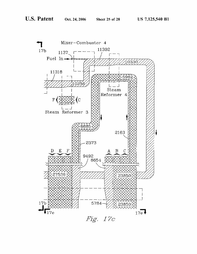
U.S. Patent Oct. 24, 2006 Sheet 25 of 28 US 7,125,540 Bl
*1 17b
Mixer—Combustor 4
11392 1137 I
Fuel In—»>4w-i^r
Fig. 17c
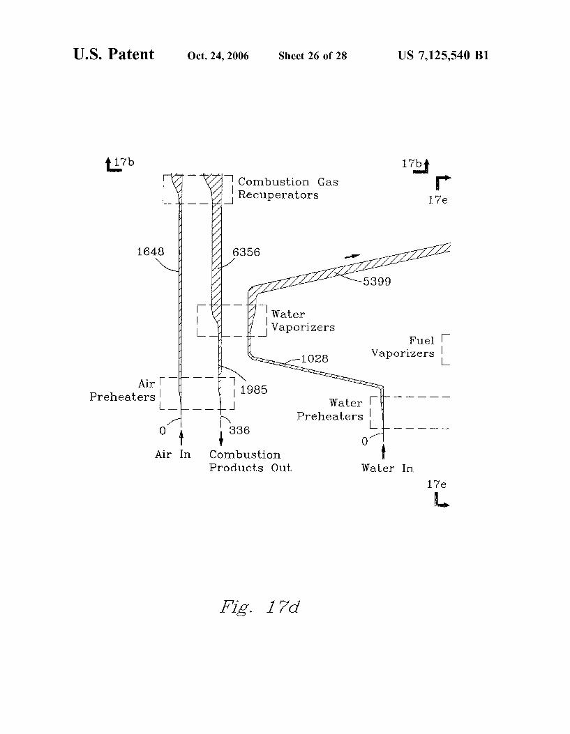
U.S. Patent Oct. 24, 2006 Sheet 26 of 28 US 7,125,540 Bl
17b 17bi —I Combustion Gas
Recupera to r s
1648
Air r P rehea t e r s
Combust ion P roduc t s Out Water In
17 e
Fig. 17d

U.S. Patent Oct. 24,2006 Sheet 27 of 28 US 7,125,540 Bl
17c,
Iso —Octane In
17d
J Reformate
Out
Fig. 17e
U . S . P a t e n t Oct. 24,2006 Sheet 28 of 28 US 7,125,540 Bl
Fig. 18
FIELD OF THE INVENTION
US 7,125,540 Bl 1 2
MICROSYSTEM PROCESS NETWORKS exit and exits the microcomponent device. A processing device is connected to the first exit of the microcomponent
This invention was made with Government support under device. The processing device is capable of modifying the Contract DE-AC0676RL01830 awarded by the U.S. Depart- stream by a second unit operation. An outlet of the process-ment of Energy. The Government has certain rights in the 5 ing device is connected to a second inlet of the microcom-invention. ponent device through a second inlet and the second array of
microchannels is connected to the second inlet and a second exit is connected to the second array of microchannels.
„ ^. i. i ^ ^ • i i i - 1 During operation, the stream re-enters the microcomponent ine present invention relates to microchannel devices and io . . . . . . ' . . . . . .. ; , • , 1 j • tu t t.1 -P •<- device and is distributed among the second array ol micro-
particularly microchannel devices that are capable ol unit , . , . e . . , - , process operations involving the transfer of mass or heat. c h a m l e l s w h e r e a t h l r d u m t °Perati°n is performed on the
stream, and the stream exits through the second exit and BACKGROUND OF THE INVENTION exits the microcomponent device. In a preferred embodi-
. , ment, the third unit operation is the same as the first unit Systems involving heat or mass transfer are crucial to our operation—this is an example of ortho-cascading. The
industrialized society. Examples of such systems include: invention also includes methods that use the microcompo-power generation, chemical processing systems, and heating nent apparatus in the manner described, and cooling systems. For more than 100 years, scientists and i n another aspect, the invention provides a microchannel engineers have endeavored to increase the efficiency or 20 device comprising: a first zone, wherein during operation, at reduce the cost ol these systems. j e a s t o n e u n j t p r o c e s s operation is performed, and that,
Battelle, Pacific Northwest National Laboratories and d u r i n g 0peration, functions at a first temperature; a second others have been using microtechnology to develop micro- z o n e ^ d u r i n g o p e r a t i o n : functions at a second tempera-systems for carrying out processes that had previously been w h e r e i n t h e &st t a t u r e i s d i f f e r e n t t h a n t h e conducted using lar larger equipment, inese systems, which 25 J * ^ J
. _ r-, -n- • -, 1 second temperature; and contain leatures 01 1 millimeter (mm) or less, may potentially change heat and mass transfer processing in ways a microchannel heat exchanger that is disposed between the analogous to the changes that miniaturization have brought first z o n e aad t h e s e c o n d z o n e D u r i n g operation, a stream to computing. Microsystems can be advantageously used in flows f r o m t h e s e c o n d z o n e through the microchannel heat small scale operations, such as in vehicles. Microsystems 30 e x c h a n g e r to the first zone and subsequently flows back that can be economically mass-produced can be connected t h r o u h ^ m i c r o c h a n n e l h e a t e x c h a n g e r to t h e seCond together to accomplish large scale operations. A, , . .. .,, . ,, . , 1 1 .
0 . . „. . „ , , p , p zone. Also, during operation, within the microchannel heat The production ol hydrogen Irom hydrocarbon luels, lor , , , . , j i . .1 a • . p , , , i r , • • 1 1 exchanger, heat is exchanged between the stream flowing use in luel cells, are one example 01 an application that has „ ., , . ., „ . ,., „ . , , „ . ^ r. 1 11 1 ^ irom the second zone to the first zone and the stream flowing been proposed lor microsystems. Fuel cells are electro- 35 „ , „ , , , , ,
, • 1 j • .1 . . r 1 j - .1 . 1 irom the first zone to the second zone; and the heat chemical devices that convert luel energy directly to elec- . trical energy. For example, in a process known as steam exchanger has a thermal power density of at least 0.6 W per reforming, a microsystem can convert a hydrocarbon fuel (or c u b l c centimeter and an exergetic efficiency of at least 80%. an alcohol such as methanol or ethanol) to hydrogen and T h e invention also includes methods that use the micro-carbon monoxide. The hydrogen is fed to a luel cell that 40 c h a m l e l d e v l c e m t h e m a m l e r described. In a preferred reacts the hydrogen and oxygen (from the air) to produce embodiment, the heat exchanger in the above-described water and an electric current. The CO could, in a reaction microchannel device has an exergetic efficiency of at least known as the water gas shift reaction, be reacted with water 8 0 % (preferably 85 to 95%) when the first zone is at a to produce additional hydrogen and carbon dioxide. Thus, temperature of 600° C. and the second zone has a tempera-fuel cells offer many potential advantages over conventional 45 ^ o f 2 0 0 ° C - - t h l s d o e s n o t m e a n t h a t t h e a PP a r a t u s « internal combustion engines-fuel cells can be more energy d e f i n e d t o 0Pemte at t h e s e temperatures, rather these tern-efficient and they do not produce nitrogen oxides and ozone peratures provide a precise temperature for testing apparatus that are the primary unhealthfiil components of smog. f o r exergetic efficiency.
Despite long and intensive efforts, there remains a need In another aspect, the invention provides a microstructure for enei^y efficient and cost effective systems for carrying 50 architecture comprising at least two layers: a first layer out operations involving heat or mass transfer. There is also comprising a continuous flow microchannel, and a second a need for compact systems or microcomponent systems for layer adjacent the first layer that comprises at least one conducting processes that are conventionally carried out on microchannel. The first layer and the second layer cooperate a larger scale. This patent describes new solutions for more to form at least two unit operations, and the flow micro-efficient and cost-effective systems utilizing microcompo- 55 channel forms at least a portion of the at least two unit nent technology. operations. Preferably, the flow microchannel is substan
tially straight. In one preferred embodiment, the two unit SUMMARY OF THE INVENTION process operations are heating a gas and vaporizing a liquid.
In another preferred emodiment, the flow microchannel In a first aspect, the present invention provides a micro- 60 forms at least a portion of at least three unit operations,
component apparatus for conducting unit operations com- In a further aspect, the invention provides microchannel prising a microcomponent device having a first inlet, first apparatus in which the microchannel walls have gaps that exit, a first array of microchannels, and a second array of allow pressure to equalize among the microchannels. In microchannels. During operation, a stream enters the first another aspect, the invention provides a microcomponent inlet of the microcomponent device and is distributed among 65 apparatus that contains a catalyst chamber in which there are the first array of microchannels and a first unit operation is upper and lower flow paths separated by a space, and upper performed on the stream. The stream exits through the first and lower catalyst supports. The upper catalyst support is
US 7,125,540 Bl
disposed substantially in the upper flow path, and the lower catalyst support is disposed substantially in the lower flow path.
In yet another aspect, the invention provides a microchan-nel apparatus comprising a header, at least two flow micro- 5 channels, and at least two orifices. Each orifice connects the header with each flow microchannel. The ratio of the cross-sectional area of each orifice to the cross-sectional area of the flow microchannels connected to said orifices is between 0.0005 and 0.1, more preferably between 0.001 and 0.05. 10 This apparatus is especially useful as a water vaporizer.
In still another aspect, the invention provides a method of exchanging heat in a microchannel device, in which a first stream in a microchannel exchanges heat with a second stream, wherein the first stream remains in the microchannel 15 and, subsequently, the first stream exchanges heat with a third stream without leaving the microchannel.
In a further aspect, the invention provides a method of conducting unit operations in microcomponent apparatus comprising: performing a first unit operation on a first 20 stream in a first microcomponent cell, subsequent to the first unit operation, performing a second, discrete unit operation on the first stream to make a modified stream, then in a second microcomponent cell, performing the first unit operation on the modified stream, to accomplish a single unit 25 operation for the same purpose as the a first unit operation on the first stream. In a preferred embodiment, the first stream is a heat exchange fluid and the first unit operation in a microcomponent cell is heat exchange, with heat being transferred from the first stream to provide heat for an 30 endothermic process; where the second unit operation modifying first stream comprises reheating the first fluid by reheating from a heat source or by adding additional fuel or oxygen and performing combustion reactions. Examples of endothermic processes include drying, boiling, evaporation, 35 endothermic chemical reactions, and desorption. In another preferred embodiment, heat is transferred for an exothermic process, such as an exothermic chemical reaction, or a sorption process such as a gas into a liquid or a gas onto a solid. In another preferred embodiment, the first unit opera- 40 tion comprises a chemical reaction, such as steam reforming, and the second unit process comprises mass transfer, such as adding additional hydrocarbon reactant to first stream.
In another aspect, the invention provides a microcomponent device for conducting unit operations comprising: a 45 first microcomponent device having a first inlet, first exit, first header, a first array of microchannels and a second array of microchannels. The first inlet is connected to the first array of microchannels. The first array of microchannels are connected to a first exit that is connected to the first header. 50 During operation, a first stream enters the first inlet of the first microcomponent device and is distributed among the first array of microchannels and a first unit operation is performed on the first stream, the first stream then passes through the first exit into the first header. The first header 55 being is capable of modifying the first stream by a second unit operation. The first header is connected to a second array of microchannels within the first device. During operation, the first stream enters the first microcomponent device and is distributed among the second array of microchannels 60 wherein the first unit operation is again performed on the first stream.
The invention further provides a method of transforming exergy in a microcomponent device in which a portion of the chemical exergy of a first stream is converted to physical 65 exergy and a portion of this physical exergy is transferred to chemical exergy in a second stream. The first stream and the
second stream do not mix. The step of transferring at least a portion of said physical exergy to chemical exergy in a second stream has a an exergetic efficiency of at least 50%; and the step of converting at least a portion of the first chemical exergy to physical exergy has a thermal power density of at least 0.6 watts per cubuc centimeter.
The invention also provides a method of designing a microcomponent apparatus, comprising using exergetic analysis to analyze a system having microcomponents that are involved in at least one unit process operation; and designing a change in the microcomponent apparatus based on that exergetic analysis. The exergy analysis can be used to identify the causes and calculate the magnitude of exergy losses.
The invention also provides a chemical process system comprising: a fuel cell; a heat pump; and a chemical conversion unit capable of producing fuel for the fuel cell. During operation, the fuel cell produces heat at a first temperature, and the heat pump increases the temperature of the heat to a higher temperature. Heat from the heat pump is transferred to the chemical conversion unit. Preferably, the heat pump contains a compressor.
While the invention recognizes that there are numerous approaches to energetic analysis, "exergetic efficiency" of a specified percent refers to the exergetic efficiency as calculated by the specific method described herein.
The invention, in various aspects and embodiments can provide numerous advantages including: reduced exergy destruction, higher power densities, process intensification, improved exergetic efficiency, reduced costs of construction and operation, new abilities to perform operations in small volumes, relatively high flow rates and reduced temperatures, reductions in size, and improvements in durability.
The subject matter of the present invention is distinctly claimed in the concluding portion of this specification. However, both the organization and method of operation, together with further advantages and objects thereof, may further be understood by reference to the following description taken in connection with accompanying drawings wherein like reference characters refer to like elements.
GLOSSARY OF TERMS
A "cell" refers to a separate component, or a volume within an integrated device, in which at least one unit operation is performed. In preferred embodiments, the cell has a width less than about 20 cm, length less than about 20 cm, and height less than about 3 cm.
"Flow microchannel" refers to a microchannel through which a fluid flows during normal operation of an apparatus.
"MicroChannel" refers to a channel having at least one dimension that is about 2 mm or less, preferably 1 mm or less. The length of a microchannel is defined as the furthest direction a fluid could flow, during normal operation, before hitting a wall. The width and depth are perpendicular to length, and to each other, and, in the illustrated embodiments, width is measured in the plane of a shim or layer.
"Microcomponent" is a component that, during operation, is part of a unit process operation and has a dimension that is 2 mm or less, preferably 1 mm or less.
"Microcomponent cell" is a cell within a device wherein the cell contains microcomponents.
"Ortho-cascading" refers to a process in which first unit operation is performed on a first stream in a first microcomponent cell, subsequent to the first unit operation, a second, discrete unit operation is performed on the first stream to
US 7,125,540 Bl 5 6
make a modified stream, then in a second cell, the first unit FIG. 15a is a top down view of a reaction chamber layer operation is again performed on the modified stream, to shim in a reactor. accomplish a single unit operation. The first unit operations FIG. 15b is a blow up of a reaction chamber showing in the first and second cells has the same purpose. dimensions in mils.
"Unit process operation" refers to an operation in which 5 FIG. 15c is a top down view of a spacer shim in the the chemical or physical properties of a fluid stream are reaction chamber layer. modified. Unit process operations (also called unit opera- FIG. 15d is a top down view of a shim in the heat tions) may include modifications in a fluid stream's tern- exchanger layer of a reactor. perature, pressure or composition. Typical unit process FIG. 15e is a top down view of an endplate of a reactor, operations include pumping, compressing, expanding, valv- 10 piG. 16 is a diagram of exergy balance for a compact ing, mixing, heating, cooling, reacting, and separating. steam reforming unit.
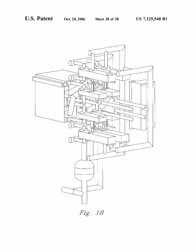
"Thermal power density" refers to the heat transfer rate F I G 1 7 i s a d i a g r a m 0 f enthalpy balance for a compact divided by volume of the device, where volume of the steam reforming unit device is the sum of stream volume involved in heat transfer F I G 1 8 i s a b l a c k aad w h i t e r e n d i t i o n o f t h e c o m p a c t and the walls between the streams, calculated in the portion 15 steam reforming unit shown in FIG 10 of the device where there is a significant amount of heat transfer (thus excluding long stretches of piping, etc.). DETAILED DESCRIPTION
BRIEF DESCRIPTION OF THE DRAWINGS T h e i n v e n t i o n i n v o i v e s a c o r e 0 f c i o s e i y r e i a t e d concepts 2 0 that are perhaps most easily understood by dividing the
The patent or application file contains at least one drawing descriptions into the three aspects of: ortho-cascading, exer-executed in color. Copies of this patent with color drawings g e t i c e f f i c i e n c y : a n d s y s t em construction. In many embodi-will be provided by the Office upon request and payment of m e n t S 5 t h e s e ^ c l o s e l y r e l a t e d c o n c e p t s . F o r e x a m p i e :
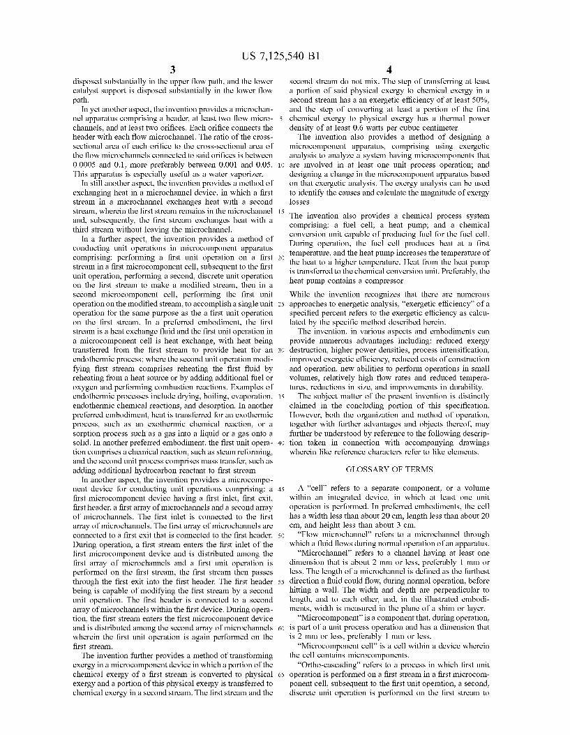
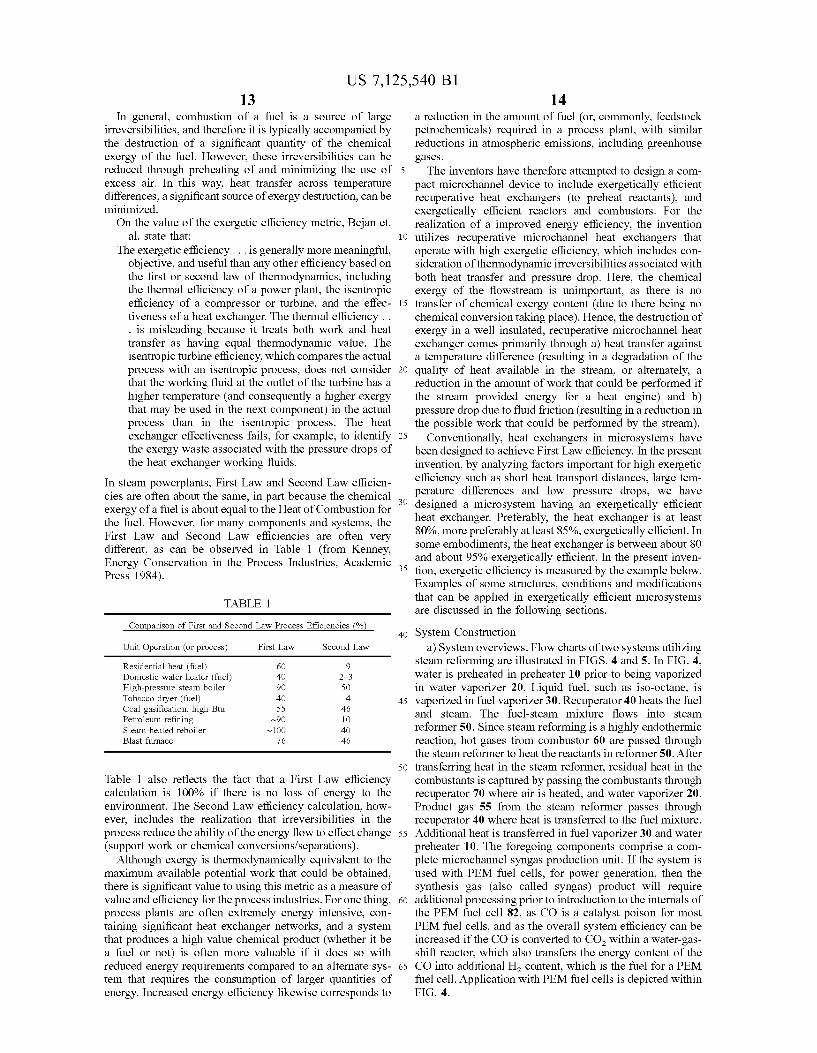
me necessary tee. ortho-cascading can contribute to exergetic efficiency, and FIG. 1 illustrates a hot gas reinjection scheme for reform- 25 Ysrious preferred embodiments of system constructions can
ing hydrocarbons. b e ortho-cascaded, exergetically efficient, or both. Some FIG. 2 illustrates representative increases in overall sys- preferred embodiments of each of these aspects are dis-
tem efficiency of a fuel cell power generation system oper- cussed below, ated using reformate produced utilizing hot gas reinjection.
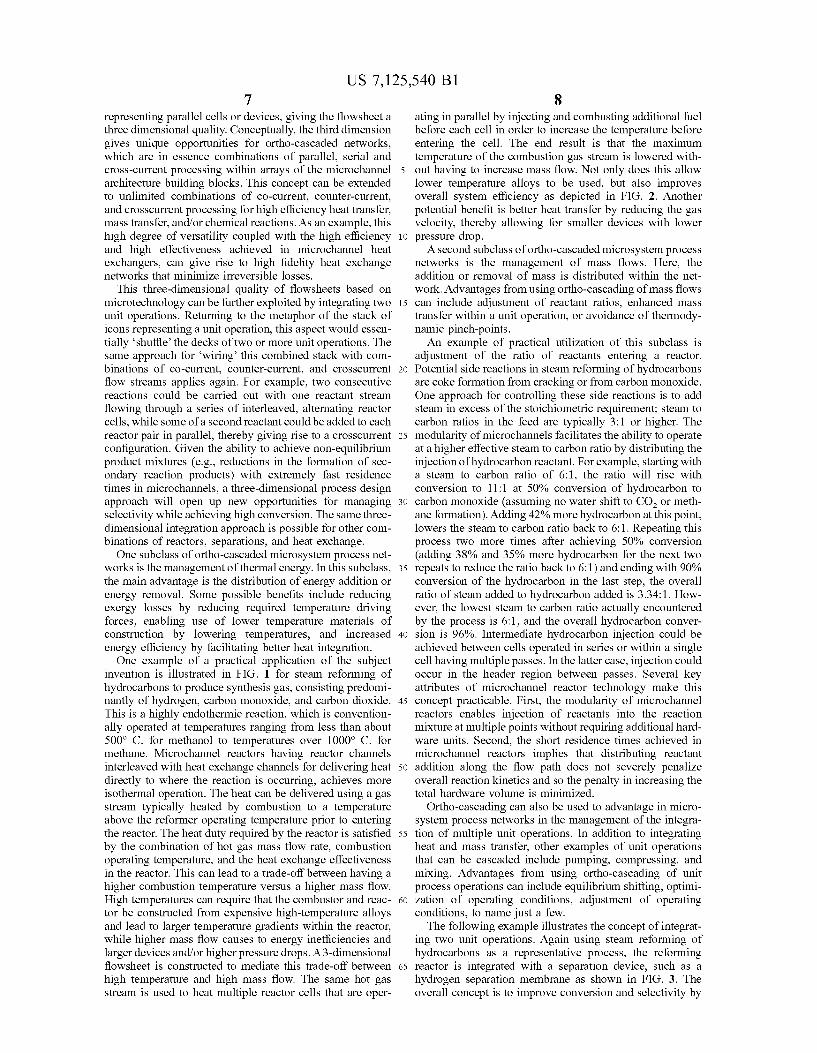
FIG. 3 is a schematic diagram illustrating integration of 3 0 Ortno-Cascaaing steam reformer reactors and hydrogen separation mem- Conventional process flowsheet development involves branes identifying a sequence of unit operations, such as chemical
FIG. 4 is a flow diagram for a compact steam reforming reactors, separations, and heat exchangers, which are inter-unit with fuel cell connected by process streams to form a process train. At the
FIG. 5 is a flow diagram for a compact steam reforming 35 m o s t simplistic level, raw materials are fed to the process at unit with solid oxide fuel cell o n e e n ^ ' ^ m a t e r i a l passes through a network of unit
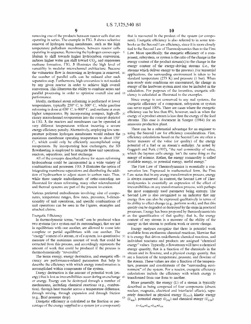
FIG. 6 is a top down view of a shim for a microchannel operations, and products come out the other end. This . . . inherent two-dimensional structure gives rise to the terms heat exchanger. , . 6
^ T ^ _ • , r , , ,. , , JJ- ,. up-stream and down-stream in relerence to processes. FIG. 7 is a graph oi observed versus predicted enective- „ • , , . . , ,. . ,
r ,, , , , 40 Superimposed on this inherent two-dimensional structure ness lor the heat exchanger. r r
P , , , . , ,, , „ „ „ . , j . , JJ. . are concepts oi recycle and multiple stages. Recycle streams FIG. 8 is a graph oi energy and exergy efficiency as a „, - ^ "li 1 f- ^ J- \ • 1 JJ
j , i . j - , TT ^ j . . , , , , flow opposite to the general direction oi material flow junction oi heating rate lor a microchannel heat exchanger. ^ , \, ^ „ „ ,
„-,„ „ . , P , • n • r through the system; they can flow irom a down-stream FIG. 9 is a graph oi exergy destruction as a lunction oi . . i. i * *i. • i * ^ *i.
, . & ^ . , , , , process to an up-stream process or back to the inlet oi the heating rate lor a microchannel heat exchanger. .. A<- i*- i * n J-
0 . . 0 45 generating process. Multiple stages generally relers to cases FIG. 10 is a color drawing of a compact steam reforming w h e r e a s i n g l e ^ o p e r a t i o n i s a c c o m p l i s h e d in a sequence
of steps, such as a series of continuous stirred tank reactors FIG. 11a is a top down view of a heat exchanger shim in ( C S T R ) o r a t r a i n o f m i xe r .Set t lers in solvent extraction,
a microchannel recuperator. Conventional flowsheet development is driven largely by FIG. lib is a top down view of a shim in a microchannel 5 0 e c o n o m i e s o f s c a l e . T h e r e m a y b e r a r e c a s e s w h e r e ^
recuperator. engineer would choose to divide up a unit operation into a FIG. 12a is a top down view of a shim of a microchannel sequence of parallel vessels or trains, such as adding parallel
neat excnanger. trains in a capacity expansion. Dividing up a unit operation FIG. 12b is a top down view of a shim of a microchannel i n t o a sequence of parallel trains substantially increases the
heat exchanger. 5 5 c o s t 0 f conventional process technology. This is in marked FIG. 13a is a top down view of a shim of a microchannel contrast to microtechnology where the smallest building
heat exchanger. block is a microchannel, which are assembled into arrays FIG. lib is a top down view of a shim of a microchannel that form cells. Practical constraints, desired operational
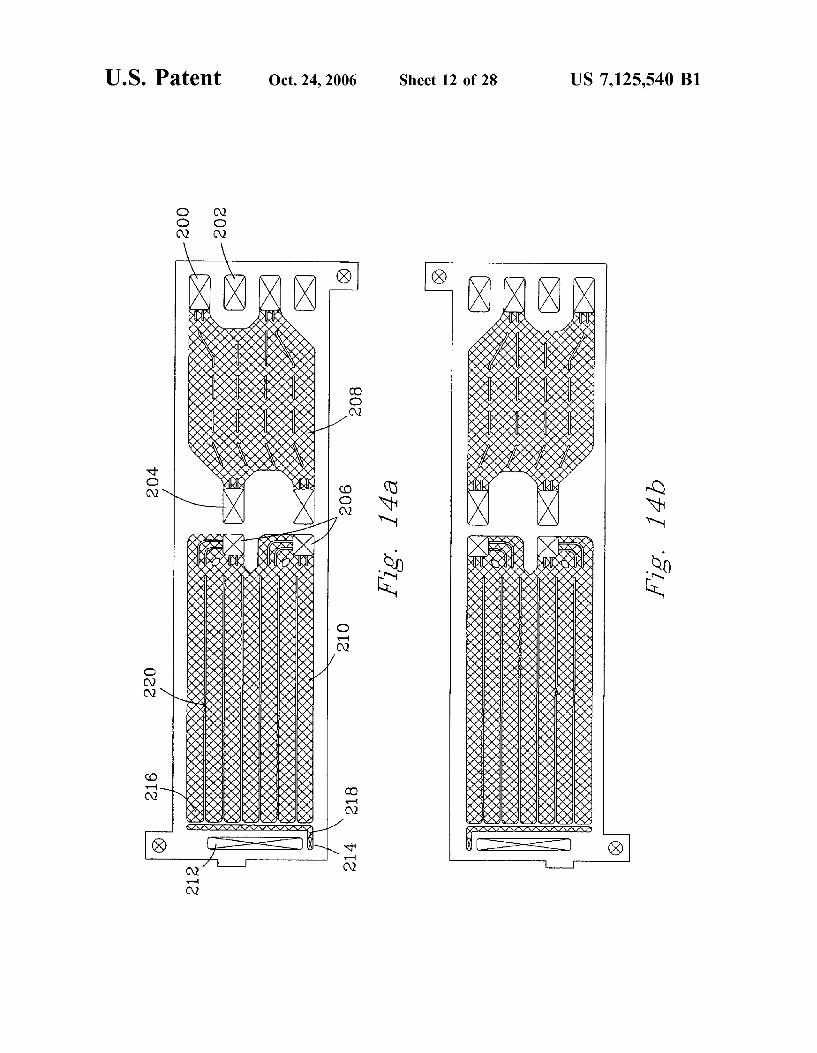
heat exchanger. characteristics, and flow distribution issues typically limit FIG. 14a is a top down view of a vaporizer shim in a 60 the size of a single cell. Consequently, multiple cells can be
microchannel recuperator. included in a device with multiple devices in parallel trains FIG. 14b is a bottom up view of a vaporizer shim in a to achieve the necessary throughput,
microchannel recuperator. This invention recognizes and takes advantage of the FIG. 14c is a top down view of a heat exchanger shim in inherent modularity of the microtechnology in process net-
a microchannel recuperator. 65 work development. The modularity allows a system FIG. 14d is a bottom up view of a heat exchanger shim in designer to mentally replace a single icon representing a
a microchannel recuperator. single unit operation on a flowsheet with a stack of icons
US 7,125,540 Bl 8
representing parallel cells or devices, giving the flowsheet a three dimensional quality. Conceptually, the third dimension gives unique opportunities for ortho-cascaded networks, which are in essence combinations of parallel, serial and cross-current processing within arrays of the microchannel 5 architecture building blocks. This concept can be extended to unlimited combinations of co-current, counter-current, and crosscurrent processing for high eflSciency heat transfer, mass transfer, and/or chemical reactions. As an example, this high degree of versatility coupled with the high eflSciency 10 and high effectiveness achieved in microchannel heat exchangers, can give rise to high fidelity heat exchange networks that minimize irreversible losses.
This three-dimensional quality of flowsheets based on microtechnology can be further exploited by integrating two 15 unit operations. Returning to the metaphor of the stack of icons representing a unit operation, this aspect would essentially 'shuffle' the decks of two or more unit operations. The same approach for 'wiring' this combined stack with combinations of co-current, counter-current, and crosscurrent 20 flow streams applies again. For example, two consecutive reactions could be carried out with one reactant stream flowing through a series of interleaved, alternating reactor cells, while some of a second reactant could be added to each reactor pair in parallel, thereby giving rise to a crosscurrent 25 configuration. Given the ability to achieve non-equilibrium product mixtures (e.g., reductions in the formation of secondary reaction products) with extremely fast residence times in microchannels, a three-dimensional process design approach will open up new opportunities for managing 30 selectivity while achieving high conversion. The same three-dimensional integration approach is possible for other combinations of reactors, separations, and heat exchange.
One subclass of ortho-cascaded microsystem process networks is the management of thermal energy. In this subclass, 35 the main advantage is the distribution of energy addition or energy removal. Some possible benefits include reducing exergy losses by reducing required temperature driving forces, enabling use of lower temperature materials of construction by lowering temperatures, and increased 40 energy efficiency by facilitating better heat integration.
One example of a practical application of the subject invention is illustrated in FIG. 1 for steam reforming of hydrocarbons to produce synthesis gas, consisting predominantly of hydrogen, carbon monoxide, and carbon dioxide. 45 This is a highly endothermic reaction, which is conventionally operated at temperatures ranging from less than about 500° C. for methanol to temperatures over 1000° C. for methane. MicroChannel reactors having reactor channels interleaved with heat exchange channels for delivering heat 50 directly to where the reaction is occurring, achieves more isothermal operation. The heat can be delivered using a gas stream typically heated by combustion to a temperature above the reformer operating temperature prior to entering the reactor. The heat duty required by the reactor is satisfied 55 by the combination of hot gas mass flow rate, combustion operating temperature, and the heat exchange eflectiveness in the reactor. This can lead to a trade-oflf between having a higher combustion temperature versus a higher mass flow. High temperatures can require that the combustor and reac- 60 tor be constructed from expensive high-temperature alloys and lead to larger temperature gradients within the reactor, while higher mass flow causes to energy inefficiencies and larger devices and/or higher pressure drops. A 3-dimensional flowsheet is constructed to mediate this trade-off between 65 high temperature and high mass flow. The same hot gas stream is used to heat multiple reactor cells that are oper
ating in parallel by injecting and combusting additional fuel before each cell in order to increase the temperature before entering the cell. The end result is that the maximum temperature of the combustion gas stream is lowered without having to increase mass flow. Not only does this allow lower temperature alloys to be used, but also improves overall system efficiency as depicted in FIG. 2. Another potential benefit is better heat transfer by reducing the gas velocity, thereby allowing for smaller devices with lower pressure drop.
A second subclass of ortho-cascaded microsystem process networks is the management of mass flows. Here, the addition or removal of mass is distributed within the network. Advantages from using ortho-cascading of mass flows can include adjustment of reactant ratios, enhanced mass transfer within a unit operation, or avoidance of thermody-namic pinch-points.
An example of practical utilization of this subclass is adjustment of the ratio of reactants entering a reactor. Potential side reactions in steam reforming of hydrocarbons are coke formation from cracking or from carbon monoxide. One approach for controlling these side reactions is to add steam in excess of the stoichiometric requirement; steam to carbon ratios in the feed are typically 3:1 or higher. The modularity of microchannels facilitates the ability to operate at a higher effective steam to carbon ratio by distributing the injection of hydrocarbon reactant. For example, starting with a steam to carbon ratio of 6:1, the ratio will rise with conversion to 11:1 at 50% conversion of hydrocarbon to carbon monoxide (assuming no water shift to C0 2 or methane formation). Adding 42% more hydrocarbon at this point, lowers the steam to carbon ratio back to 6:1. Repeating this process two more times after achieving 50% conversion (adding 38% and 35% more hydrocarbon for the next two repeats to reduce the ratio back to 6:1) and ending with 90% conversion of the hydrocarbon in the last step, the overall ratio of steam added to hydrocarbon added is 3.34:1. However, the lowest steam to carbon ratio actually encountered by the process is 6:1, and the overall hydrocarbon conversion is 96%. Intermediate hydrocarbon injection could be achieved between cells operated in series or within a single cell having multiple passes. In the latter case, injection could occur in the header region between passes. Several key attributes of microchannel reactor technology make this concept practicable. First, the modularity of microchannel reactors enables injection of reactants into the reaction mixture at multiple points without requiring additional hardware units. Second, the short residence times achieved in microchannel reactors implies that distributing reactant addition along the flow path does not severely penalize overall reaction kinetics and so the penalty in increasing the total hardware volume is minimized.
Ortho-cascading can also be used to advantage in microsystem process networks in the management of the integration of multiple unit operations. In addition to integrating heat and mass transfer, other examples of unit operations that can be cascaded include pumping, compressing, and mixing. Advantages from using ortho-cascading of unit process operations can include equilibrium shifting, optimization of operating conditions, adjustment of operating conditions, to name just a few.
The following example illustrates the concept of integrating two unit operations. Again using steam reforming of hydrocarbons as a representative process, the reforming reactor is integrated with a separation device, such as a hydrogen separation membrane as shown in FIG. 3. The overall concept is to improve conversion and selectivity by
US 7,125,540 Bl 10
removing one of the products between reactor cells that are operating in series. The example in FIG. 3 shows selective removal of hydrogen using membranes, such as the high temperature palladium membranes, between reactor cells operating in sequence. Removing the hydrogen causes equi- 5 librium to shift towards higher hydrocarbon conversion, induces higher water gas shift toward C 0 2 , and suppresses methane formation. FIG. 3 illustrates the high level of versatility in modular microchannel architecture. Because the volumetric flow is decreasing as hydrogen is removed, 10 the number of parallel cells can be reduced after each separation step. Furthermore, high conversion is not needed by any given reactor in order to achieve high overall conversion. This illustrates the ability to combine series and parallel processing in order to optimize overall size and 15 performance.
Ideally, methanol steam reforming is performed at lower temperatures, typically 250° C. to 300° C , while gasoline reforming is done at 650° C. to 800° C. and methane at even higher temperatures. By incorporating compact, high-efli- 20 ciency microchannel recuperators into the concept depicted in FIG. 3, the reactors and membranes can be operated at very different temperatures without incurring a severe energy efficiency penalty. Alternatively, employing low temperature polymer hydrogen membranes would reduce the 25 maximum membrane operating temperature to about 150° C , which could only be efficiently accomplished using recuperators. By incorporating heat exchangers, the 3D flowsheeting is employed to integrate three unit operations, reactors, separations, and heat exchange. 30
All of the concepts described above for steam reforming hydrocarbons could be incorporated in a wide variety of combinations and processes. FIG. 3 illustrates the option of integrating membrane separations and distributing the addition of hydrocarbon to adjust steam to carbon ratio. Thus, 35 while three sample embodiments of ortho-cascading are illustrated for steam reforming, many other microchemical and thermal systems are part of the present invention.
Various preferred embodiments involving: size of components, temperature ranges, flow rates, pressures, 3-dimen-sionality of unit operations, and specific combinations of unit operations can be seen in the Figures, examples and attached claims.
Exergetic Efficiency 45 In thermodynamic terms, "work" can be produced when
two systems (or a system and its surroundings), that are not in equilibrium with one another, are allowed to come into complete or partial equilibrium with one another. The "exergy" content of a stream, or of a system, is a quantitative 50 measure of the maximum amount of work that could be extracted from this process, and accordingly represents the amount of work that could be produced if the process is thermodynamically "reversible".
The terms exergy, exergy destruction, and exergetic effi- 55 ciency are performance-related parameters that help to describe the efficiency with which energy transformation is accomplished within components of the system.
Exergy destruction is the amount of potential work (exergy) that is lost as irreversibilities occur during an exchange 60 or energy. Exergy can be destroyed through a number of mechanisms, including chemical reactions (e.g., combustion), through heat transfer across a temperature difference, through mixing, through expansion and through friction (e.g., fluid pressure drop). 65
Exergetic efficiency is calculated as the fraction or percentage of the exergy supplied to a system (or a component)
that is recovered in the product of the system (or component). Exergetic efficiency is also referred to in some textbooks as the Second Law efficiency, since it is more closely tied to the Second Law of Thermodynamics than to the First Law. More specifically, the exergetic efficiency of a component, subsystem, or system is the ratio of the change in the exergy content of the product stream(s) to the change in the exergy content of the exergy-driving streams (i.e., the streams which deliver exergy to the process). For terrestrial applications, the surrounding environment is taken to be standard temperature (273 K) and pressure (1 bar). When non-steady state conditions are encountered, the change in exergy of the hardware system must also be included in the calculation. For purposes of the invention, exergetic efficiency is calculated as illustrated in the examples.
Since exergy is not conserved in any real systems, the exergetic efficiency of a component, subsystem or system can never equal 100%. There are cases where the exergetic efficiency can be less than 0%, however, such as when the exergy of a product stream is less than the exergy of the feed streams. This case is document in Szargut (1984) for an ammonia production plant.
There can be a substantial advantage for an engineer to using the Second Law for efficiency considerations. First, efficiency calculations based on the Second Law are often a better measure of the value (or quality) of the energy potential of a fuel or an stream's enthalpy. As noted by Gaggioli and Petit (1997), "the real commodity of value, which the layman calls energy, isn't the same thing as the energy of science. Rather, the energy commodity is called available energy, or potential energy, useful energy."
The First Law of Thermodynamics is essentially a conservation law. Expressed in mathematical form, the First Law states that in any energy transformation process, energy is always conserved. In contrast, the Second Law of Thermodynamics is essentially an expression of the effect of irreversibilities on any transformation process, with perhaps the most commonly used parameter being entropy. The Second Law is also recognized as an indicator that any energy flow can also be expressed qualitatively in terms of its ability to effect change (e.g., perform work), and that this quality can be degraded or destroyed by the steps in practical processes. Exergy has been proposed by thermodynamicists as the quantification of that quality; that is, the exergy content of any stream is a measure of the ability of the energy in that stream to perform work or create change.
Exergy analyses recognize that there is potential work available from exothermic chemical reactions, likewise that it is exergy that drives endothermic chemical reactions, and individual reactants and products are assigned "chemical exergy" values. Typically, a flowstream will have a chemical exergy quantity, that is a function of the chemicals in the stream and its flowrate, and a physical exergy quantiy, that are a function of the temperature, pressure, and flowrate of the stream. These values are also a function of the temperature, pressure and constitutents of the "surrounding environment" of the system. For a reactor, exergetic efficiency calculations include the efficiency with which exergy is transformed from one form to another.
More generally, the exergy (E) of a stream is typically described as being composed of four components (absent nuclear, magnetic, electrical and interfacial effects), separately described as physical exergy (E^^), kinetic exergy (JiKE), potential exergy ( E ^ ) and chemical exergy (E c i 7) .
E =EpH+EKE+EpE+ECH

US 7,125,540 Bl 11 12
The kinetic and potential exergy terms are equivalent to where k is the ratio of specific heats. Likewise, the exergy kinetic and potential energy, and can typically be assumed to increase of the cold stream is:
£2-£1=m^r0{[(r2/r1)-i-i«(r2/r1)]-[i«(iyp1)' /d(k-be small compared to the other terms. However, this assumption needs to be carefully considered in each case, as i)]} there are notable exceptions. 5
The physical exergy term is typically calculated based F o r a reversible process, there would be pressure drop within upon methods described in Szargut et. al. Exergy Analysis of flther s t rfm ' a n d t h e r e w o u l d b e no temperature difference rj,, 1^1 - 1 j i v j i i i - i n TT • between the streams at any point at which heat is exchanged, ihermal, Chemical, and Metallurgical Processes, Hemi- _ , , , „J * . „ „ TT
D
u T> ti <- (M\QQ\ n,r (M\QI\ AT>- t 1 That is, we would have T1=T4 and T2=T3. However, revers-sphere Publ. Co. (1988), Moran (1982), and Beian et. al., ,„ ., , . ^ , • ^ * , , , • r- ^ J _£ . _ . X • • • T-,T-, T • T, , ,• 10 ible processes exist only in textbooks, and in tact there can Ihermal Design Optimization, Wiley-lnterscience Pubhca- , , c .., , , , ..jj- rj,, 0 . r J . be no heat transfer without temperature differences, there-tion (1996), and is mathematically based upon the following ^ fQr a r e a l i s t i c r e c u p e r a t i v e h e a t e x c h a n g e r : s o m e e x e r g y
expression for fluid flow within an open system: i s d e s t r o y e d ( j , ^ ^ t h i s c a n quantitatively can be -i=H-H0-TJS-S0) expressed as:
EDES=yET,-E4)-[E2-El)
^secand law (^-E' ^1(E3-E4)
where H and S represent the enthalpy and entropy of the fluid stream at the point of interest, H0 and S0 represent the In accordance with the Second Law of Thermodynamics, enthalpy and entropy of the same stream if brought to the some exergy is destroyed in the recuperative heat exchanger same temperature and pressure as the environment (T0 and example, just as some quantity of exergy must be destroyed P0). Derivations of this expression are found in a number of 20 in any energy transformation. In the example, the loss in texts, including those already mentioned. Note that this exergy is physically accomplished through friction (pressure equation is similar to, but should not be coniused with, the d roP) and heat transfer (against a temperature difference). Gibbs function for free enerev The latter feature is further demonstrated by the observation
— , , „ , , . , r • „ that T,<T, for real heat exchangers. ine value lor the chemical exergy oi a stream is typically 25 ^n. u • 1 <-• +u + J-
.£'J . , , When no chemical reactions or other exergy translers are assigned from a table of chemical exergies, based upon a c c o m p l i s h e d b y a component, the exergetic efficiency of a consideration of the surrounding environment. Substantial d e v i c e i s t y p i c a l l y c a i c u i a t e d to be the increase in physical work has been done to define reference chemical exergies e x e r g y w i t h i n t h e p r o d u c t s t r e a m d i v i d e d b y t h e d e c r e a s e i n
for a number of chemicals in terrestrial settings, and the physical exergy within the other stream. For this case of the reader is again referred to the previously cited literature for 30 recuperative heat exchanger, the exergetic efficiency (or additional information. Second Law efficiency) is therefore:
It is perhaps instructive to examine the method of exergy analysis for a simple case, where a hot gas is used for the purpose of heating a cool gas. In this example, we will 35 This example further demonstrated another previously men-assume that a recuperative heat exchanger is operating with tioned feature: All real-world processes result in some two fluid streams, each consisting of the same ideal gas with degree of degradation in the useful work that could be the same mass flow rates, and with constant specific heats accomplished by any energy stream. and no chemical reactions. Likewise, in this example, we There is perhaps no better example than the case of a will assume that there are no significant changes in potential 40 simple, steam powerplant, producing electricity from a fossil energy or kinetic energy of either gas stream. ^el- In this case, the chemical exergy of the iuel is converted
T ,, • ,, • n , • , to heat in the furnace at a high temperature, perhaps exceed-In this case, the previous equation lor physical exergy can . _„„„„ „ . . . . . 0 . . r , ,
, , „ , , ing 2000 C. with this heat being used to produce superheated steam, typically at less than 600° C. If we assume that
EPH/mcpT0=[(T/T0)-l-ln(T/T0)]-[ln (P/P0f(k-l>] 45 the environment is at about 25° C, then applying the
efficiency derivation of Camot for heat engines, we would where m is the mass flow rate or molar flow rate for the gas, expect that a reversible heat engine could extract useiul cp is the specific heat of the gas, and k is the ratio of specific work at a First Law efficiency of heats for the gas. The first bracketed term is the contribution of the temperature of the gas to the physical exergy of the 50 stream, and the second bracketed term is the contribution of ei!« 1™ = [1 - (25 + 273)/(600 + 273)] x 100% = 65.8% the pressure of the gas to the physical exergy of the stream. In each bracket, the exergy contribution is specific to the state of the environment, which is consistent with the However, conventional steam powerplants typically produce definition of exergy as being the amount of work that could 55 electricity at First Law efficiencies of only about 35-40%. theoretically be extracted from the stream if it were to be This supports two observations: 1) that the conversion of the reversibly brought into equilibrium with the environment. fossil fuel's chemical exergy to physical exergy within the
, . . . , , . . . „ , combustion gases and then to physical exergy within the Assuming that the inlet and outlet conditions of the stream s u p e r h e a t e d s t e a m : a t o n l y 6oo° C, results in the destruction to be heated are T^P andT P2, respectively, and assuming 60 o f 34 2„/o o f t h e c h e m i c a l e o f t h a t ^ aad 2 ) t h a t
that the inlet and outlet conditions of the heating stream are t h e r e i s s i i f i c a n t a d d i t i o n a l d e s t m c t i o n 0f e x e r g y i n t h e
1,, P, and 1., P., respectively, then since there are no • , r .u . , . r™. „ . „ ,3' 3 . , r .4 r •" . , , . , remainder ol the steam powerplant. this lact is ol course
changes in kinetic energy, potential energy, or chemical w e U ^ ^ t o i n e e r S 5 w h o a l s o a p p r e c i a t e t h a t t h e l a r g e s t
exergy, the expression lor the amount ol exergy that is given r , . . • • .. . , . • • e-7' r . e e source ol exergy destruction in the steam powerplant is in
P y • 65 fact the irreversible transfer of heat from the combustion E3-E4=mcpT0{[(T3/T4)-l-ln(T3/T4)]-[ln(P3/P4f'V'- gases to the steam, which is typically only heated to several
i)]} hundred degrees.
US 7,125,540 Bl 13 14
In general, combustion of a fuel is a source of large irreversibilities, and therefore it is typically accompanied by the destruction of a significant quantity of the chemical exergy of the fuel. However, these irreversibilities can be reduced through preheating of and minimizing the use of 5 excess air. In this way, heat transfer across temperature differences, a significant source of exergy destruction, can be minimized.
On the value of the exergetic efficiency metric, Bejan et. al. state that: 10
The exergetic efficiency . . . is generally more meaningful, objective, and useful than any other efficiency based on the first or second law of thermodynamics, including the thermal efficiency of a power plant, the isentropic efficiency of a compressor or turbine, and the effec- 15 tiveness of a heat exchanger. The thermal efficiency . . . is misleading because it treats both work and heat transfer as having equal thermodynamic value. The isentropic turbine efficiency, which compares the actual process with an isentropic process, does not consider 20 that the working fluid at the outlet of the turbine has a higher temperature (and consequently a higher exergy that may be used in the next component) in the actual process than in the isentropic process. The heat exchanger effectiveness fails, for example, to identify 25 the exergy waste associated with the pressure drops of the heat exchanger working fluids.
In steam powerplants, First Law and Second Law efficiencies are often about the same, in part because the chemical exergy of a fuel is about equal to the Heat of Combustion for the fuel. However, for many components and systems, the First Law and Second Law efficiencies are often very different, as can be observed in Table 1 (from Kenney, Energy Conservation in the Process Industries, Academic Press 1984).
TABLE 1
Comparison of First and Second Law Process Efficiencies (%)
Unit Operation (or process) First Law Second Law
Residential heat (fuel) Domestic water heater (fuel) High-pressure steam boiler Tobacco dryer (fuel) Coal gasification, high Btu Petroleum refining Steam-heated reboiler Blast furnace
60 40 90 40 55
-90 -100
76
9 2-3 50 4
46 10 40 46
30
35
40
45
50 Table 1 also reflects the fact that a First Law efficiency calculation is 100% if there is no loss of energy to the environment. The Second Law efficiency calculation, however, includes the realization that irreversibilities in the process reduce the ability of the energy flow to effect change 55 (support work or chemical conversions/separations).
Although exergy is thermodynamically equivalent to the maximum available potential work that could be obtained, there is significant value to using this metric as a measure of value and efficiency for the process industries. For one thing, process plants are often extremely energy intensive, containing significant heat exchanger networks, and a system that produces a high value chemical product (whether it be a fuel or not) is often more valuable if it does so with reduced energy requirements compared to an alternate system that requires the consumption of larger quantities of energy. Increased energy efficiency likewise corresponds to
60
65
a reduction in the amount of fuel (or, commonly, feedstock petrochemicals) required in a process plant, with similar reductions in atmospheric emissions, including greenhouse gases.
The inventors have therefore attempted to design a compact microchannel device to include exergetically efficient recuperative heat exchangers (to preheat reactants), and exergetically efficient reactors and combustors. For the realization of a improved energy efficiency, the invention utilizes recuperative microchannel heat exchangers that operate with high exergetic efficiency, which includes consideration of thermodynamic irreversibilities associated with both heat transfer and pressure drop. Here, the chemical exergy of the flowstream is unimportant, as there is no transfer of chemical exergy content (due to there being no chemical conversion taking place). Hence, the destruction of exergy in a well insulated, recuperative microchannel heat exchanger comes primarily through a) heat transfer against a temperature difference (resulting in a degradation of the quality of heat available in the stream, or alternately, a reduction in the amount of work that could be performed if the stream provided energy for a heat engine) and b) pressure drop due to fluid friction (resulting in a reduction in the possible work that could be performed by the stream).
Conventionally, heat exchangers in microsystems have been designed to achieve First Law efficiency. In the present invention, by analyzing factors important for high exergetic efficiency such as short heat transport distances, large temperature differences and low pressure drops, we have designed a microsystem having an exergetically efficient heat exchanger. Preferably, the heat exchanger is at least 80%, more preferably at least 85%, exergetically efficient. In some embodiments, the heat exchanger is between about 80 and about 95% exergetically efficient. In the present invention, exergetic efficiency is measured by the example below. Examples of some structures, conditions and modifications that can be applied in exergetically efficient microsystems are discussed in the following sections.
System Construction a) System overviews. Flow charts of two systems utilizing
steam reforming are illustrated in FIGS. 4 and 5. In FIG. 4, water is preheated in preheater 10 prior to being vaporized in water vaporizer 20. Liquid fuel, such as iso-octane, is vaporized in fuel vaporizer 30. Recuperator 40 heats the fuel and steam. The fuel-steam mixture flows into steam reformer 50. Since steam reforming is a highly endothermic reaction, hot gases from combustor 60 are passed through the steam reformer to heat the reactants in reformer 50. After transferring heat in the steam reformer, residual heat in the combustants is captured by passing the combustants through recuperator 70 where air is heated, and water vaporizer 20. Product gas 55 from the steam reformer passes through recuperator 40 where heat is transferred to the fuel mixture. Additional heat is transferred in fuel vaporizer 30 and water preheater 10. The foregoing components comprise a complete microchannel syngas production unit. If the system is used with PEM fuel cells, for power generation, then the synthesis gas (also called syngas) product will require additional processing prior to introduction to the internals of the PEM fuel cell 82, as CO is a catalyst poison for most PEM fuel cells, and as the overall system efficiency can be increased if the CO is converted to C0 2 within a water-gas-shift reactor, which also transfers the energy content of the CO into additional H2 content, which is the fuel for a PEM fuel cell. Application with PEM fuel cells is depicted within FIG. 4.

US 7,125,540 Bl 15 16
The objective of the compact microchannel steam reforming unit, schematically illustrated in the left side of FIG. 4, is the production of hydrogen-rich gas from hydrocarbon feedstock, for applications where there are advantages through the realization of compact, lightweight hardware for 5 hydrogen gas production. Examples include power production for both stationary and mobile applications (e.g., vehicular applications), where the product gas is subsequently processed as necessary in accordance with the fuel requirements of a fuel cell and for the production of chemi- 10 cals where hydrogen or synthesis gas is a feedstock to the chemical process that is employed. This flowsheet indicates steam reforming of liquid hydrocarbons, however, other embodiments could utilize gaseous hydrocarbons (e.g., methane). 15
A compact microchannel steam reforming unit can include:
MicroChannel catalytic steam reforming reactors (1 or more)—which contain integral microchannel heat exchangers so that the endothermic steam reforming 20 reaction receives its heat from the combustion gas stream
MicroChannel recuperative heat exchangers (2 or more)— which provide for eflScient preheating of the stream reforming stream and the combustion stream, utilizing 25 (respectively) the stream reforming products and the combustion products as the source of heat from each.
MicroChannel vaporizers for generating steam and gaseous hydrocarbons. In the system configuration that is depicted in FIG. 4, the heat of vaporization for both 30 streams is essentially provided by the latent heat of the combustion (product) stream, however other system configurations are possible where some of the heat of vaporization of one or both streams are provided, in part, from the latent heat that is present in the steam 35 reforming (product) stream, or where the heat of vaporization for either or both the water and the hydrocarbon stream are separately provided.
MicroChannel or other compact units for the provision of heat to the heat-providing stream (e.g., a compact 40 combustion unit).
A highly efficient recuperative microchannel heat exchanger in this system is identified as Recuperator 1, which has been designed to function with an exergetic efficiency exceeding 85%. The exergy analysis of this com- 45 ponent and the other components of the system is presented in the following section.
If the unit is used with solid oxide fuel cells (SOFCs), then no additional processing of the syngas product is required. In this case, a further advantage is realized, wherein the heat 50 from the high temperature SOFC is at a high enough temperature so that it can be used as process heat for the endothermic steam reforming reactor. FIG. 5 shows one possible system configuration of the Compact MicroChannel Steam Reforming Unit when used with a solid oxide fuel 55 cell. In this system, fuel is vaporized in vaporizer 210, combined with steam from water vaporizer 220 and heated in recuperator 230. The heated stream is reacted in reformer 240. The reformer 240 is integrated with a combustor that supplies additional heat. The resulting reformate is heated to 60 900° C. to 1100° C , preferably about 1000° C , in recuperator 250 and passed to solid oxide fuel cell 260 to generate electrical power 270. Waste heat from the solid oxide fuel cell can be recovered by passing the hot waste gases back through the system as shown in FIG. 5. 65
In general, the design capacity of the compact microchannel synthesis gas production unit could be increased by
either increasing the size and throughput of each component, proportionally, or by utilizing a design for the system where multiple process trains are processed in parallel, or by some combination of both. For the case where multiple process trains are processed in parallel, there are additionally other features that can support the energy efficient production of synthesis gas, such as by operating each train (and component) at a point that is near or at its most efficient conditions, and digitally turning up (or down) the production rate by turning on (or off) individual process trains.
It is also apparent that individual components can be separately plumbed into the system without exceeding the contemplated bounds of the invention, so that not all components have to be part of the same integral hardware unit.
Hydrocarbon feedstocks for which this unit is considered include intermediate-length-chain hydrocarbons (e.g., iso-octane) and short-chain hydrocarbons (e.g., methane, ethane, etc), plus alcohols (e.g., methanol, ethanol, etc). The production of syngas from complex mixtures (e.g., gasoline or diesel fuel) is contemplated; however, additional unit operations may be required in order to deal with constituents that are problematic for reforming. Example constituents of concern include sulfur-containing compounds, aromatics, and detergents.
For the heat-providing stream, energy can be provided through either a) the combustion of a portion of the hydrocarbon feedstock, a portion of the steam reformer gas product, a fuel-containing stream that comes from downstream processing (e.g., the anode effluent of a fuel cell), or some other fuel stream or b) process heat from some other system (such as a high temperature, solid-oxide fuel cell), or c) some combination of a) and b) together.
Many other embodiments are contemplated within the scope of this invention. For example, highly efficient recuperative microchannel heat exchangers could be utilized as part of a C 0 2 collection system (which is based on temperature swing absorption) and for preheating of reactants to and cooling of products from the reactors.
b) Shim designs and exergetic efficiency calculations. The following section describes, with accompanying figures, shim designs that were fabricated and tested. The section also includes some generalized discussion of component design, modifications, and operating parameters that are applicable in a wide variety of devices and systems. Although components are described as part of a steam reforming apparatus, it should be understood that the following designs and other descriptions are not limited to the steam reforming process, but are generally applicable to systems employing microchannel components.
Example: Highly Exergetic Recuperative Heat Exchanger A microchannel recuperative heat exchanger was
designed, fabricated and experimentally demonstrated to be highly efficient, with an exergetic efficiency (considering both heat transfer against a temperature difference and pressure drop) that was demonstrated to be greater than 80%. The microchannel heat exchanger was designed to achieve a desired heat transfer effectiveness of 0.85. The design is described below. Several conservative assumptions were made in the initial design model including:
calculating the Nusselt number for both constant temperature and constant heat flux boundary conditions and taking the minimum (constant heat flux is the more correct boundary for the recuperator)
giving full weight to longitudinal conduction in the metal at the outside edges of the exchanger

US 7,125,540 Bl 17 18
using an abbreviated pressure drop calculation with an extended entrance section to estimate shim pressure drop rather than a short entrance followed by an expanding region.
A microchannel recuperative heat exchanger was constructed that consisted of 10 pairs of shims consisting of 20 mil (0.50 mm) shims partially etched to a depth of 10 mil (0.25 mm). The entire device was constructed of 316 stainless steel. The shim design for shim "A" is shown in FIG. 6. The "B" shim is the mirror image of the "A" shim except that it connects to the alternate set of header holes. The device was covered top and bottom by 50-mil (1.25 mm) thick cover plates. The shims was assembled with the A and B plates facing each other: Top Plate, A, B, A, B . . . A, B, Bottom Plate. The top plate has 2 header holes that align with the header holes 610, 620 in Plate A and the bottom plate has 2 header holes that connect to the header holes in Plate B. The two gases flow countercurrent in the heat exchange section and in the headers flowing in the stack direction flow in the same direction (e.g. the initially hot gas enters through headers 610 and leaves through headers 620 while the initially cold gas enters through headers 630 and leaves through headers 640). The header holes were etched from both sides with all other areas on the back side masked off. Prior to bonding, a nickel coating was applied over the steel plates and the unit was diffusion bonded. The tolerance on the alignment pin holes could not be achieved in the etching process so the holes were made slightly undersized and manually reamed to the correct size. External headers consisting of one half of a Vs" tube (0.0325 inch wall) with a Vs" tube "tee" leg were welded onto the two stacks. The external headers combine the two internal header holes and provided for a connection to the test stand. A full tubing tee leg was centered on the shim width.
The design included a 100 mil (0.25 cm) bonding perimeter in all regions that require a seal. In the shim entrance regions, which are supporting bonding in the shim directly above, two 20-mil wide ribs were placed in the 250 mil opening dividing it into three 70 mil passages. This approach successfully sealed the device.
The internal support ribs in the heat exchange section were spaced at approximately quarter-inch intervals. Leak-proof bonding is not required in the region of the internal ribs so the major function of the ribs is to limit the deflection 45 of the wall due to differential pressures. The four slanted ribs are intended to help distribute flow. In the section with flow directed along straight ribs, the support ribs are intermittent. This allows flow redistribution if needed. It is believed that if flow is not sufficiently uniform, heat transfer effectiveness 50 may suffer significantly. The interrupted support rib is expected to have a small positive effect on heat transfer and introduce a small penalty in flow friction.
The shim stock from slice of stainless indicates that the 0.020 inch thickness material has a tolerance of ±0.003 inch. 55 A single sampling of one shim A and one shim B (6 measurement points on each) indicated that the shim material was about 20.6 mil on the shim A sample and 20.9 mil on the shim B sample, which is well within the 3 mil tolerance. The depth of the etching on these two shim 60 samples averaged 10.0 mil on shim A and 9.8 mil on shim B. No measurements were made of a standard thickness gauge for comparison and the calibration of the micrometer was expired so this data should be considered as indication only. The overall thickness of the recuperator after testing 65 was 0.4973 inch compared to a target thickness of 0.5000 inches (2*0.050"+20*0.020").
30
35
The size of the bonded unit was measured to be 3.020 inches by 1.50 inches by 0.50 inches (2.265 in3, or 37.12 cm3). Pressure taps and thermocouples were located at the tees into which each exchanger inlets/outlets are connected. Kao-wool insulation was applied to the exchanger and wrapped in aluminum tape.
Heat exchanger tests were conducted by selecting the desired nitrogen flow and furnace temperature and then waiting for temperatures on the exchanger to stabilize. All data was taken at steady state. The time required to achieve a steady state condition was between 15 and 45 minutes depending on temperature and flow rate. The slow dynamics are believed to be primarily due to the long flowpath and thermal mass associated with the heated gas flow path prior to entering the exchanger. This could be modified to allow more rapid collection of data. No attempt was made to sort out the dynamic response of the recuperator itself from the data. A total of 21 steady-state test conditions were recorded and evaluated with full insulation on the exchanger, with heating rates being varied from 86 watts to 943 watts. The highest thermal power density (heat rate per unit hardware volume) was therefore 25.4 watts/cm3. The system was operated with nitrogen as the working fluid at flow rates varying from 30 to 126 slpm at inlet pressures for the cold fluid ranging from 4.76 to 30.95 psig. The same stream was used for both the cold fluid and the hot fluid, with the cold fluid being additionally heated after leaving the heat exchanger before being returned to the unit and serving as the hot fluid. Inlet temperatures for the cold fluid were generally about 23-26° C. Outlet temperatures for the cold fluid were raised to various levels, ranging from 188° C. to 473° C. The inlet temperature for the hot fluid was varied from 220-575° C. with the outlet temperature varying from 61-145° C.
Upon first examination of the data it was clear that the model was slightly conservative in predicting effectiveness (i.e. the actual exchanger effectiveness was higher than the model prediction). The first adjustment made to the model prior to reducing the data was to force the model to use the constant heat flux boundary condition in estimating the Nusselt number rather than the constant temperature boundary condition. The constant heat flux boundary is clearly the more correct boundary for the recuperator and the minimum Nusselt number was used simply as a conservatism in design.
The model predictions of effectiveness (using the constant heat flux boundary condition) are plotted against the observed effectiveness in FIG. 7. The area for heat transfer in the model is taken as 2.80xl0~2 m2, consisting of a region 4.755xl0~2 m long and 3.099xl0~2 m wide. This assumed area neglects the area in the entrance regions to the headers.
The exergetic efficiency of the microchannel heat exchanger was calculated from the data by using the technique for ideal gases (Bejan, Tsatsaronis, and Moran, 1996), taking into account both temperature data and pressure data, and are shown in FIG. 8. FIG. 9 additionally shows the amount of exergy destruction as a function of heating rate
A preferred embodiment of a steam reformer system is illustrated in FIGS. 10-15. This system is called "the Compact Microchannnel Steam Reforming Unit" in the following discussion. A schematic overall view of the apparatus 101 is illustrated in color in FIG. 10 (a black and white rendition is included as FIG. 18). Fresh air enters through air preheater inlet 106 and is warmed in the air preheater (gray block). The air is split into four streams moving through conduits 110 (green) to four recuperators 124, 140 (pink). Each of these recuperators contains a recuperative heat

US 7,125,540 Bl 19 20
exchanger 120 and water vaporizer 122. Hot air exits recuperator 120 into header 112 (gray) and is mixed with fuel in tube 102 (red) which travels to combustor 104 (red). The resulting combustants travel through header 118 to reactor 114 (blue). The gas runs in series through four cells. 5 In each cell, heat from the combustants is transferred to drive the endothermic production of hydrogen. At the reactor, the combustant stream is connected in series while the reactant stream is connected in parallel. After passing through the first cell, the gas leaves the reactor 114 through 10 header 116 (purple) and hydrogen gas is injected through an inlet (not shown) in the header 116. The hydrogen gas spontaneously ignites, adding heat to return the gas to the temperature at which the gas first entered the reactor. The gas then reenters the reactor to again drive the formation of 15 hydrogen. After passing through the fourth cell, the combustant gases exits through a header 134 (pink) where it is split into four separate streams and used to vaporize water. The combustant streams are recombined in header 108 and used to warm up air in the air preheater before being 20 exhausted.
In the other fluid stream, water (which optionally could come through a preheater) comes into each of four water vaporizers 122, is converted to steam, and passes through headers 126 (blue) to fuel vaporizer 132 (yellow) where the 25 steam is mixed with fuel from a fuel inlet (not shown) and each of the four mixtures passes through a header 138 (yellow) into a cell of reactor 114 where hydrogen is produced. In a preferred embodiment, both the reformate stream and the combustant (heat exchange) fluid streams 30 exit the reactor at about 750C. Heat from the reformate stream is recovered in recuperator 130 and vaporizer 132 and the reformate exits the device (through gray tubes).
The design for the air preheater was an interleaved microchannel heat exchanger 1000 that consisted of 10 pairs 35 of shims consisting of 20 mil (0.50 mm) shims partially etched to a depth of 10 mil (0.25 mm). The entire device was constructed of 316L stainless steel. The shim design for shim "A" is shown in FIG. 12a. The "B" shim, shown in FIG. 12b, is the same as the "A" shim except that it connects to the 40 alternate set of header holes. The device is covered top and bottom by 50-mil (1.25 mm) thick cover plates. The shims are assembled: Top Plate, A, B, A, B . . . A, B, Bottom Plate. The top plate has 20 header holes that align with the header holes 1010, 1020 in Plate A and the bottom plate has 20 45 header holes that connect to the header holes in Plate B. The two gases flow countercurrent in the heat exchange section and in the headers (e.g. the initially hot gas enters through headers 1010 and leaves through headers 1020 while the initially cold gas enters through headers 1030 and leaves 50 through headers 1040). The shims were 7.1 inch long and 3.0 inch wide. The heat exchanger was bonded as described above.
A similar design for another interleaved heat exchanger is illustrated in FIGS. 13a and lib. In this exchanger, there 55 were 20 pairs of shims consisting of 31 mil (0.78 mm) shims partially etched to a depth of 10 mil (0.25 mm), that is, a channel depth of 10 mil. These shims measured 2.9 inch wide by 3.3 inch long (excluding alignment tabs). This heat exchanger is not illustrated in FIG. 10, but could, for 60 example, be attached to the reformate carrying tubes to condense water.
The shim design for a combined recuperative heat exchanger 130 and fuel vaporizer 132 is illustrated in FIGS. 11a and 11 b. These shims were 17 mil thick with an etch 65 depth of 6 or 7 mil. Each shim is 1.5 inch wide (excluding assembly alignment holes 152, which are cut off after
bonding) and 5.34 inches long. The shims shown in FIGS. 11a and lib were stacked in alternating layers capped by end plates having inlet and outlet fluid headers. The flow micro-channels were structurally supported by 10 mil thick lands. In the heat exchanger layer, hot reformate gas enters through inlets 162, and travels through the layer to outlet 150. While fluid flow flows within a single microchannel, that fluid participates in three unit operations. In the illustrated embodiment, in region 158 heat is transferred to reactants prior to entering the reactor, in region 156 heat is transferred to fuel vaporizer 176, and in region 154, 172 heat is transferred to water. The heated water exits through outlet 170. Vaporized fuel exits through outlets 174. Reactants enter through inlets 178 and exits through outlets 160. Preferably there are at least two layers with a fuel vaporizer and at least one heat exchanger layer, more preferably there are at least three layers with a fuel vaporizer and at least two heat exchanger layers. Each of the layers preferably has a thickness of between 0.1 and 1 mm. While the description refers to a steam reforming process, it should be recognized that the inventive concepts apply to a wide variety of reactions and unit process operations.
Shims for a combination water vaporizer 120/heat exchanger 122 are shown in FIGS. 14a 14d. In this micro-channel device 124, the etched face of the shim illustrated in FIG. 14a was placed adjacent to its mirror image (the etched face of the shim illustrated in FIG. 14b) to form a shim pair A. The mirror image shims shown in FIGS. 14c and 14d were similarly matched to form shim pair B. Shim pairs A and B were alternatively stacked (A-B-A-B- . . . ) with 10 A pairs and 11 B pairs. In the air heat exchanger portion of this device, cool air from the air preheater enters through inlets 204, move through microchannels 208, where the air is heated, and hot air exits outlet channels 200 after which the heated air flows to the combustor. Water enters header 218 through inlet 214. The water passes through laser machined orifices 216 and into microchannels 210, where the water is converted to steam and exits through steam outlets 206. Several features are worth noting in this construction. Lands 220 can be provided for structural support; however, it is preferred that the lands have gaps that help equalize pressure in the microchannels, especially in regions where microchannels are curved. The orifices help provide even flow through all the microchannels and reduce the incidence of water spurting through the microchannels. In a preferred embodiment, flow microchannels for a water vaporizer have a height of about 100 to about 2500 micrometers; a width of about 1.3 to about 13 millimeters; and a length of about 1 to about 30 centimeters. A heat exchange fluid, such as a combustant stream, flows through the shims shown in FIGS. 14c and d. The hot combustants enter through inlets 202, passes through microchannels 226 and 224 to combustion exhaust 212. In region 222, heat is transferred to air, while in region 220, heat is transferred to a water vaporizer—thus illustrating an example in which a heat exchange fluid can be used for multiple, separate unit operations without leaving the same flow microchannel. While two specific unit operations are illustrated, it should be recognized that this technique can be used efficiently for any desired combination of unit operations. The top and bottom plates (not shown) were 0.048 inch thick steel plates having header holes for water inlet, steam outlet, heat exchange fluid inlets and outlets, and air inlets and outlets.
The shim construction for the reactor 114 is shown in FIGS. 15a-e. The reactor contained 75 reaction chamber layers alternating with 76 heat exchanger layers. Each reaction chamber layer consisted of a pair of mirror-image
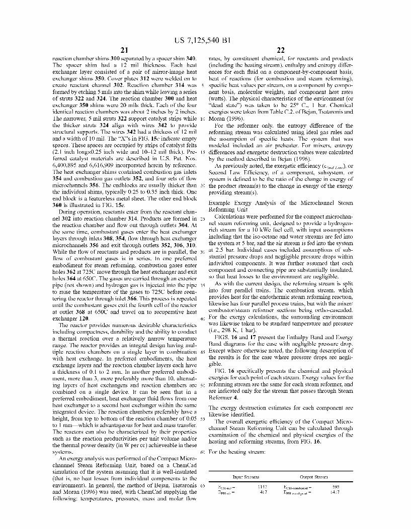
US 7,125,540 Bl 21 22
reaction chamber shims 300 separated by a spacer shim 340. The spacer shim had a 12 mil thickness. Each heat exchanger layer consisted of a pair of mirror-image heat exchanger shims 350. Cover plates 312 were welded on to create reactant channel 302. Reaction chamber 314 was 5 formed by etching 5 mils into the shim while leaving a series of struts 322 and 324. The reaction chamber 300 and heat exchanger 350 shims were 20 mils thick. Each of the four identical reaction chambers was about 2 inches by 2 inches. The narrower, 5 mil struts 322 support catalyst strips while 10 the thicker struts 324 align with wires 342 to provide structural supports. The wires 342 had a thickess of 12 mil and a width of 10 mil. The "X"s in FIG. 15c indicate empty spaces. These spaces are occupied by strips of catalyst felts (2.1 inch longx0.25 inch wide and 10-12 mil thick). Pre- 15 ferred catalyst materials are described in U.S. Pat. Nos. 6,400,895 and 6,616,909 incorporated herein by reference. The heat exchanger shims contained combustion gas inlets 354 and combustion gas outlets 352, and four sets of flow microchannels 356. The endblocks are usually thicker than 20 the individual shims, typically 0.25 to 0.35 inch thick. One end block is a featureless metal sheet. The other end block 360 is illustrated in FIG. 15e.
During operation, reactants enter from the reactant channel 302 into reaction chamber 314. Products are formed in 25 the reaction chamber and flow out through outlets 304. At the same time, combustant gases enter the heat exchanger layers through inlets 308, 354, flow through heat exchanger microchannels 356 and exit through outlets 352, 306, 310. While the flow of reactants and products are in parallel, the 30 flow of combustant gases is in series. In one preferred embodiment for steam reforming, combustion gases enter holes 362 at 725C move through the heat exchanger and exit holes 364 at 650C. The gases are carried through an exterior pipe (not shown) and hydrogen gas is injected into the pipe 35 to raise the temperature of the gases to 725C before reen-tering the reactor through inlet 366. This process is repeated until the combustant gases exit the fourth cell of the reactor at outlet 368 at 650C and travel on to recuperative heat exchanger 120. 40
The reactor provides numerous desirable characteristics including compactness, durability and the ability to conduct a thermal reaction over a relatively narrow temperature range. The reactor provides an integral design having multiple reaction chambers on a single layer in combination 45 with heat exchange. In preferred embodiments, the heat exchange layers and the reaction chamber layers each have a thickness of 0.1 to 2 mm. In another preferred embodiment, more than 3, more preferably more than 10, alternating layers of heat exchangers and reaction chambers are 50 combined on a single device. It can be seen that in a preferred embodiment, heat exchanger fluid flows from one heat exchanger to a second heat exchanger within the same integrated device. The reaction chambers preferably have a height, from top to bottom of the reaction chamber of 0.05 55 to 1 mm—which is advantageous for heat and mass transfer. The reactors can also be characterized by their properties such as the reaction productivities per unit volume and/or the thermal power density (in W per cc) achieveable in these systems. 60
An exergy analysis was performed of the Compact Micro-channnel Steam Reforming Unit, based on a ChemCad simulation of the system assuming that it is well-insulated (that is, no heat losses from individual components to the environment). In general, the method of Bejan, Tsataronis 65 and Moran (1996) was used, with ChemCad supplying the following: temperatures, pressures, mass and molar flow
rates, by constituent chemical, for reactants and products (including the heating stream), enthalpy and entropy differences for each fluid on a component-by-component basis, heat of reactions (for combustion and steam reforming), specific heat values per stream, on a component by component basis, molecular weights, and component heat rates (watts). The physical characteristics of the environment (or "dead state") was taken to be 25° C , 1 bar. Chemical exergies were taken from Table C.2. of Bejan, Tsataronis and Moran (1996).
For the reformer only, the entropy difference of the reforming stream was calculated using ideal gas rules and the assumption of specific heats. The system that was modeled included an air preheater. For mixers, entropy differences and exergetic destruction values were calculated by the method described in Bejan (1996).
As previously noted, the exergetic efficiency (e^rfiaw)) o r
Second Law Efficiency, of a component, subsystem, or system is defined to be the ratio of the change in exergy of the product stream(s) to the change in exergy of the exergy providing stream(s).
Example Exergy Analysis of the MicroChannel Steam Reforming Unit
Calculations were performed for the compact microchan-nel steam reforming unit, designed to provide a hydrogen-rich stream for a 10 kWe fuel cell, with input assumptions including that the iso-octane and water streams are fed into the system at 5 bar, and the air stream is fed into the system at 2.5 bar. Individual cases included assumptions of substantial pressure drops and negligible pressure drops within individual components. It was further assumed that each component and connecting pipe are substantially insulated, so that heat losses to the environment are negligible.
As with the current design, the reforming stream is split into four parallel trains. The combustion stream, which provides heat for the endothermic steam reforming reaction, likewise has four parallel process trains, but with the mixer/ combustor/steam reformer sections being ortho-cascaded. For the exergy calculations, the surrounding environment was likewise taken to be standard temperature and pressure (i.e., 298 K, 1 bar).
FIGS. 16 and 17 present the Enthalpy Band and Exergy Band diagrams for the case with negligible pressure drop. Except where otherwise noted, the following description of the results is for the case where pressure drops are negligible.
FIG. 16 specifically presents the chemical and physical exergies for each point of each stream. Exergy values for the reforming stream are the same for each steam reformer, and are indicated only for the stream that passes through Steam Reformer 4.
The exergy destruction estimates for each component are likewise identified.
The overall exergetic efficiency of the Compact Micro-channel Steam Reforming Unit can be calculated through examination of the chemical and physical exergies of the heating and reforming streams, from FIG. 16.
For the heating stream:
Input Streams Output Stream
EcH-ai
EpH-ai
1147 417
C H- c ombpr od 695 1417

US 7,125,540 Bl 23
-continued
Input Streams Output Stream
•CH-fuel =
•CH-fuel =
•CH-fuel =
•CH-fuel =
5407 1110 1110 1110
2112
10301
=10301-2112=8189 watts
For the reforming stream:
E C H - J
EpH-i
Output Stream
:eformate = 2 8 3 2 0
, f o I m a t c = 1 2 3 5
2 9 5 5 5
EcH-b<
EpH-isc
E c H - w
EpH-wa
Input
joctane "
iter =
Streams
-
25442 0
1069 0
26511
20
25
A4,TOrf„„=29555-26511=3044 watts
The oveall exergetic efficiency of the Compact MicroChannel Steam Reforming Unit is the change in exergy in the product stream (i.e., the steam reforming stream) divided by the change in exergy in the driving stream (i.e., the combustion stream), or
e2njI^,=&EprmluJ&EJrivi^=3(m/»l»9=0.3m or 37.2%
30
35
For the calculation where moderate pressure drops were assumed throughout the unit, the overall exergetic efficiency dropped to as low as 25%, due to additional exergy destruc- 40 tion through pressure drop (friction). These values compare to an overall exergetic efficiency of about 30% for the synthesis gas production subsystem of an ammonia production plant, as originally presented by Cremer (H. Cremer, "Thermodynamic Balance and Analysis of a Synthesis Gas 45 and Ammonia Plant," in Thermodynamics: Second Law Analysis, ed. R. A. Gaggioli, American Chemical Society, Washington, D . C , p. I l l , 1980) and re-presented in Szargut (1984).
Consideration of Exergy Analysis for Ortho-Cascaded Mixer-Combustors and Steam Reformers
There is a desire to keep the highest temperature in the system low enough so that stainless steel can be used. In the illustrated embodiment, this can be accomplished through the use of ortho-cascading.
In the current flowsheet, the highest temperature of any stream occurs with the combustion products that leave the Mixer-Combustor 1, at 725 C. Mixer-Combustor 1 also has the highest quantity of exergy destruction of any unit in the 6o system, 1600 watts. The literature confirms that conbustion is often a large source of exergy destruction, and in the case of the Mixer-Combustor 1, this is caused in part due to the relatively low temperature (400 C) of the air stream that enters the component. 65
Leaving the steam reformer, the combustion stream has only been dropped to 662 C, therefore allowing Mixer-
55
24 Combustor 2 to require only about Vs as much fuel as was required for Mixer-Combustor 1. Mixer-Combustors 3 and 4 receive the same benefit.
The end effect is this: When considering the subsystem consisting of the Mixer-Combustor 1 and the Steam Reformer 1, the exergetic efficiency of this subsystem is only 22.3% (as can be calculated using the exergy values of Figure (b)). When adding Mixer-Combustors 2-4 and Steam Reformers 2-4, via the ortho-cascaded route, the subsystem expands, with an upward improvement in the exergetic efficiency of the subsystem, increasing it to 52.8%. Thus an ortho-cascaded approach allows the system to simultaneously increase the exergetic efficiency of the overall system while likewise allowing the system to be constructed from relatively inexpensive, stainless steel.
Consideration of Exergy Destruction and Exergetic Efficiency with MicroChannel Steam Reformers
FIG. 16 shows that, collectively, the Steam Reformers 1^4 destroy 852 watts of exergy. Within each steam reformer, a portion of the physical exergy of the combustion gas stream is initially transferred to the reforming stream, creating an increase in its physical exergy, then a portion of its physical exergy is transformed into chemical exergy, as part of the catalytic steam reforming reaction. Generally, the exergetic efficiency of each steam reformer can be separately calculated based upon the definition of exergetic efficiency, using the information that is contained within FIG. 16. As an example, the exergetic efficiency of Steam Reformer 1 is as follows:
£2„rfiaw=(7080+845-6628-777)/(6648-5914)=520/ 734=0.708
or about 70.8%. The other steam reformers likewise operate with similar exergetic efficiencies. Since the destruction of exergy, in this case, is internal to an individual component, improvements to the exergetic efficiency of these units would have to be realized through internal design improvements.
Consideration of Exergy Destruction Within the Overall Compact MicroChannel Steam Reforming Unit
The cumulative exergy destruction of the system, totaling 5147 watts, can also be considered from FIG. 16. The principle contributors to exergy destruction within the unit are estimated to be the mixer-combustors, the combustion recuperators, the water vaporizers, and the steam reformers, with their collective exergy destruction being 4722 watts, or 91.7% of the cumulative exergy destroyed. Mixer-Combustor 1 provides the most exergy destruction, 1600 watts, or 31.1% of the total exergy that is destroyed.
The Combustion Gas Recuperators have the second highest amount of exergy destruction. Air enters these units at 137 C, and is heated to 400 C by the combustion gases, which drop from 654 C to 427 C while providing 3974 watts (physical enthalpy from FIG. 17) to the air stream. These units operates across a large temperature range (654-137=517 C), and has large terminal temperature differences (respectively, 427-137 at the low temperature end of the heat exchanger, and 654-400 at the high temperature end), which contribute to a substantial amount of exergy destruction (901 watts). The Second Law efficiency, or exergetic efficiency, of this unit is calculated from the exergy values provided in FIG. 16 as follows:
e2„rfiaw=(3013-1397)/(6169-3652)=0.642 or 64.2%

US 7,125,540 Bl 25 26
By comparison, the Reformate Recuperators present a high degree of exergetic efficiency, with only 120 watts of exergy being destroyed within this unit. Here, steam and iso-octane enter the unit at 174 C, receiving heat from the reformate stream in the amount of 2870 watts (physical 5 enthalpy), and increasing in temperature to 651 C. The reformate stream cools from 700 C to 252 C in this transaction. These units therefore also act across a large temperature difference (700-174=526 C), but have much smaller terminal temperature differences than with the Com- 10 bustion Gas Recuperator. The exergetic efficiency of this unit is calculated to be:
£2„rfiaw=(3107-1527)/(3380-1680)=0.929 or 92.9%
The Combustion Gas Recuperators and the Reformate i5
Recuperators have each been designed to be very compact heat exchangers, and each has been fabricated to be integral with at least one other set of heat exchangers.
Why are the Combustion Gas Recuperators so much less exergetically efficient than the Reformate Recuperators? The 20 answer lies in the design of the entire unit, which for this embodiment has the combustion gas stream providing the heat for vaporizing water for the reforming stream. As is shown in FIG. 16, vaporizing the water requires 4371 watts of heat (thermal enthalpy), and in order to accomplish this, 25 the combustion gases must leave the Combustion Gas Recuperators at a sufficient temperature (-427 C) to provide this.
The Water Vaporizers likewise suffer from poor exergetic efficiencies, as an unavoidable consequence of the fact that water does not increase in temperature as it boils. The result 30 is that the Water Vaporizers likewise have a large terminal temperature difference at the hot end of the units (combustion gases enter at 427 C, whereas steam leaves at 160 C), and a total of 598 watts of exergy is estimated to have been destroyed in this unit. 35
In any thermo-chemical system, the exergetic efficiencies of various units are often not truly independent of each other. For the system at hand, since the Combustion Gas Recuperator must be allowed to only partly make use of its exergy for preheating the air stream, the Mixer-Combustor 1 must 40 accomplish the rest of the air heating requirement, and it therefore requires substantially greater fuel than the other Mixer-Combustors (2-4) in the ortho-cascaded train (5538 watts of chemical enthalpy for Mixer-Combustor 1 as opposed to 1137 watts of chemical enthalpy for Mixer- 45 Combustors 2-4 each). Thus, the need to vaporizer water has also accounted for a large degree of the exergy that is destroyed within Mixer-Combustor 1.
What is apparent from this assessment is that, in the present embodiment of the Compact MicroChannel Steam 50 Reforming Unit, the sequence of Water Vaporizers, Combustion Gas Recuperators, and Mixer-Combustor 1 provides for the greatest amount of exergy destruction (3099 watts, or 60.2% of the exergy destroyed). Accordingly, alternate system configurations should be explored that might improve 55 the overall exergetic efficiency of the system.
As a first consideration, the Exergy Band diagram of Figure (b) shows that the physical exergy of the combustion gas stream is at 6169 watts after leaving Steam Reformer 4. In principle, this means that if the combustion gas stream 60 were reversibly brought into physical equilibrium with the surrounding environment, it could provide up to 6169 watts of work (e.g., shaft work). This is a large value compared to the 10 kWe of electricity output that is desired from the fuel cell. While no system is truly reversible, expansion units 65 such as turbines and scroll expanders are often exergetically efficient (80% or higher).
In order to accommodate this option, additional chemical enthalpy would need to be added in the system, presumably at Mixer-Combustor 1 or prior to Mixer-Combustor 1. From Figure (a), it is observed that the chemical enthalpy that would need to be added is 3974 watts (to replace the Combustion Gas Recuperators), 4371 watts (to replace the Water Vaporizers), and 1648 watts (to replace the Air Preheaters), for a total of 9993 watts. Assuming that we were able to accomplish this, and assuming an 80% efficient expansion device, then the ratio of additional work to additional heat required is
0.80x6169/9993=0.494, or 49.4%
In actuality, an 80% efficient expansion device would result in the effluent stream of combustion gases being hot enough to provide some preheating of the combustion air, so the efficiency with which the new work would be provided is somewhat higher.
Further observing that the physical exergy of the combustion gas stream drops from 6169 watts to 3652 watts across the Combustion Gas Recuperators, then to 1747 watts across the Water Vaporizers, other options present themselves. For example, taking the same approach as in the preceeding paragraphs, replacing only the Combustion Gas Recuperators with an 80% efficient expansion device would provide 0.80x(6169-3652) watts, or 2014 watts (shaft work). This is somewhat lower than in the previous alternative, but as the additional heat to replace the Combustion Gas Recuperators is only 3974 watts, the incremental energy efficiency is
0.80x(6169-3652)/3974=0.507, or 50.7%.
This value is only slightly higher, but it avoids the problem of finding additional heat for the water vaporizer.
Overall, the system could be revised in a number of ways, for better exergetic efficiency, if a better source of heat can be found for vaporizing water. Exergetic considerations here provide another opportunity, which takes into account the observation that the Compact MicroChannel Steam Reforming Unit is designed for a system that includes a fuel cell plus other gas processing/conditioning hardware.
In particular, it is observed that a 10 kWe fuel cell will generate substantial waste heat. For example, a Proton-Exchange Membrane (PEM) fuel cell will operate at about 80 C, with about 60% efficiency (first law). The result is that there is about 6000-7000 watts of heat available from the PEM fuel cell at about 80 C. The temperature of this heat source is too low for it to provide for direct vaporization of water at 150-160 C, however, it can be upgraded via the use of a heat pump.
From a Second Law perspective, upgrading the heat from the fuel cell will require the use of exergy. For a reversible heat pump, operating between 80 C and 160 C, the Coefficient of Performance (COP) can be calculated to be:
COP=(160+273)/(160-80)=5.41
thus suggesting that the reversible heat pump needs 4371/ 5.41=808 watts of exergy, or shaft work, in order to operate. A conservative assumption would put this at, say, 25% higher, or 808x1.25=1010 watts.
Using energy from the fuel cell to vaporizer water would allow redesign of the Combustion Gas Recuperators and the Mixer-Combustor 1, so that they operate with considerably better exergetic efficiency. Conservatively assuming that the redesigned Combustion Gas Recuperators only destroy, say, 200 watts (as opposed to 120 watts of exergy destroyed in
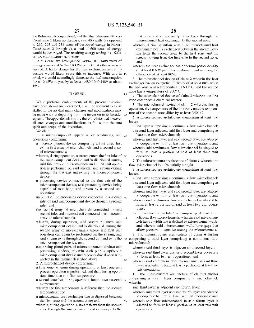
US 7,125,540 Bl 27 28
the Reformate Recuperators), and that the redesigned Mixer-Combustor 1 likewise destroys, say, 400 watts (as opposed to 266, 263 and 238 watts of destroyed exergy in Mixer-Combustors 2 through 4), a total of 600 watts of exergy would be destroyed. The resulting exergy savings is 1600+ 5 901+598-200-400=2499 watts.
In this case, we have gained 2499-1010=1489 watts of exergy, compared to the 10 kWe output that otherwise was desired. A better design for the heat exchangers and com-bustors would likely cause this to increase. With this in 10 mind, we could accordingly decrease the fuel consumption for a 10 kWe output, by at least 1.489 10=0.1489 or about 15%.
CLOSURE 15
While preferred embodiments of the present invention have been shown and described, it will be apparent to those skilled in the art that many changes and modifications may be made without departing from the invention in its broader 20 aspects. The appended claims are therefore intended to cover all such changes and modifications as fall within the true spirit and scope of the invention.
We claim: 1. A microcomponent apparatus for conducting unit 25
operations comprising: a microcomponent device comprising a first inlet, first
exit, a first array of microchannels, and a second array of microchannels;
wherein, during operation, a stream enters the first inlet of 30 the microcomponent device and is distributed among said first array of microchannels and a first unit operation is performed on said stream, said stream exiting through the first exit and exiting the microcomponent device; 35
a processing device connected to the first exit of the microcomponent device; said processing device being capable of modifying said stream by a second unit operation;
an outlet of the processing device connected to a second 40 inlet of said microcomponent device through a second inlet; and
the second array of microchannels connected to said second inlet and a second exit connected to said second array of microchannels; 45
wherein, during operation, said stream re-enters said microcomponent device and is distributed among the second array of microchannels where said first unit operation can again be performed on the stream, and said stream exits through the second exit and exits the 50 microcomponent device; and
comprising plural pairs of microcomponent devices and processing devices, wherein each pair comprises a microcomponent device and a processing device connected in the manner described above. 55
2. A microchannel device comprising: a first zone, wherein during operation, at least one unit
process operation is performed, and that, during operation, functions at a first temperature;
a second zone that, during operation, functions at a second go temperature;
wherein the first temperature is different than the second temperature; and
a microchannel heat exchanger that is disposed between the first zone and the second zone; and 65
wherein, during operation, a stream flows from the second zone through the microchannel heat exchanger to the
first zone and subsequently flows back through the microchannel heat exchanger to the second zone;
wherein, during operation, within the microchannel heat exchanger, heat is exchanged between the stream flowing from the second zone to the first zone and the stream flowing from the first zone to the second zone; and
wherein the heat exchanger has a thermal power density of at least 0.6 W per cubic centimeter and an exergetic efficiency of at least 80%.
3. The microchannel device of claim 2 wherein the heat exchanger has an exergetic efficiency of at least 80% when the first zone is at a temperature of 600° C. and the second zone has a temperature of 200° C.
4. The microchannel device of claim 3 wherein the first zone comprises a chemical reactor.
5. The microchannel device of claim 2 wherein, during operation, the temperature of the first zone and the temperature of the second zone differ by at least 350° C.
6. A micro structure architecture comprising at least two layers:
a first layer comprising a continuous flow microchannel; a second layer adjacent said first layer and comprising at
least one flow microchannel; wherein said first layer and said second layer are adapted
to cooperate to form at least two unit operations; and wherein said continuous flow microchannel is adapted to
form at least a portion of said at least three unit operations.
7. The microstructure architecture of claim 6 wherein the flow microchannel is substantially straight.
8. A microstructure architecture comprising at least two layers:
a first layer comprising a continuous flow microchannel; a second layer adjacent said first layer and comprising at
least one flow microchannel; wherein said first layer and said second layer are adapted
to cooperate to form at least two unit operations; and wherein said continuous flow microchannel is adapted to
form at least a portion of said at least two unit operations;
the microstructure architecture comprising at least three adjacent flow microchannels; wherein said microchannels have a width that is defined by microchannel walls; and wherein said microchannel walls have gaps that allow pressure to equalize among the microchannels.
9. The microstructure architecture of claim 6 further comprising a third layer comprising a continuous flow microchannel;
wherein said third layer is adjacent said second layer; wherein said third layer and said second layer cooperate
to form at least two unit operations; and wherein said continuous flow microchannel in said third
layer is adapted to form at least a portion of at least two unit operations.
10. The microstructure architecture of claim 9 further comprising a fourth layer comprising a microchannel; wherein
said third layer is adjacent said fourth layer;
wherein said third layer and said fourth layer are adapted to cooperate to form at least two unit operations; and
wherein said flow microchannel in said fourth layer is adapted to form at least a portion of at least two unit operations.

US 7,125,540 Bl 29 30
11. The micro structure architecture of claim 10 wherein said first layer and said third layer are structurally identical; and wherein said second layer and said fourth layer are structurally identical.
12. A method of exchanging heat in a microchannel 5 device, comprising:
providing a first stream in a microchannel that exchanges heat with a second stream, wherein the first stream remains in the microchannel and, subsequently, the first stream exchanges heat with a third stream without 10 leaving the microchannel.
13. A method of conducting unit operations in microcom-ponent apparatus comprising:
performing a first unit operation on a first stream in a first microcomponent device, subsequent to the first unit 15 operation, performing a second, discrete unit operation on the first stream to make a modified stream, then in a second microcomponent device, performing the first unit operation on the modified stream, to accomplish a single unit operation for the same purpose as the first 20 unit operation on the first stream;
where the first stream is a heat exchange fluid and the first unit operation in a microcomponent cell comprises heat exchange, with heat being transferred from an exothermic process to a first stream to provide cooling; and 25
wherein the second unit operation modifying first stream comprises cooling said first fluid by transferring heat to a heat sink.
14. The microcomponent apparatus of claim 1 wherein the processing device comprises a chamber having a gas inlet 30 for the addition of gaseous components.
15. A method of conducting unit operations in microcomponent apparatus comprising:
performing a first unit operation on a first stream in a first microcomponent device, subsequent to the first unit 35 operation, performing a second, discrete unit operation on the first stream to make a modified stream, then in a second microcomponent device, performing the first unit operation on the modified stream, to accomplish a single unit operation for the same purpose as the first 40 unit operation on the first stream; where the first stream comprises a heat exchange fluid and the first unit operation in a microcomponent device comprises heat exchange, with heat being transferred from the first stream to provide heat for an endothermic process; 45
wherein the second unit operation modifying first stream comprises reheating said first fluid by reheating from a heat source or by adding additional fuel or oxygen and performing combustion reactions.
16. The method of claim 15 where the endothermic 50 process is an endothermic chemical reaction.
17. The method of claim 15 where the endothermic process comprises a drying or desorption process.
18. The method of claim 15 where the endothermic process comprises boiling or evaporation. 55
19. The method of claim 13 where the exothermic process comprises an exothermic chemical reaction.
20. The method of claim 13 where the exothermic process comprises a sorption process selected from the group consisting of transforming a gas into a liquid or transforming a 60 gas onto a solid.
21. The process of claim 20 where the exothermic process comprises a phase change process.
22. The process of claim 13 where the first stream is comprised of chemical reactants and the first unit operation 65 in a microcomponent cell comprises a chemical conversion reaction;
wherein the second unit operation modifying first stream comprises mass transfer, with at least one original reactant being added to the first stream.
23. The process of claim 22 where the chemical reaction in first unit operation comprises steam reforming of hydrocarbons, and the second unit operation comprises adding additional hydrocarbon reactant to first stream.
24. A method of conducting unit operations in microcomponent apparatus comprising:
performing a first unit operation on a first stream in a first microcomponent cell, subsequent to the first unit operation, performing a second, discrete unit operation on the first stream to make a modified stream, then in a second microcomponent cell, performing the first unit operation on the modified stream, to accomplish a single unit operation for the same purpose as the a first unit operation on the first stream, where the first stream is comprised of chemical reactants and the first unit operation in a microcomponent cell comprises at least one chemical conversion reaction; and
wherein the second unit operation modifying first stream comprises a chemical separation, with at least one reaction product being preferentially removed from first stream.
25. The process of claim 24 where the chemical reaction in first unit operation comprises steam reforming of hydrocarbons, and the second unit operation comprises removing hydrogen preferentially using a gas membrane system.
26. The process of claim 24 where the chemical reaction in first unit operation comprises steam reforming of hydrocarbons, and the second unit operation comprises removing hydrogen preferentially using a sorption process.
27. The process of claim 24 where the chemical reaction in first unit operation comprises steam reforming of hydrocarbons, and the second unit operation comprises removing hydrogen preferentially using cryogenic distillation.
28. The process of claim 24 where the chemical reaction in first unit operation comprises steam reforming of hydrocarbons, and the second unit operation comprises removing hydrogen preferentially using a semipermeable membrane in an electrochemical cell.
29. The process of claim 24 where the chemical reaction in first unit operation comprises steam reforming of hydrocarbons, and the second unit operation comprises a combination of a water gas shift reactor and hydrogen separation.
30. The apparatus of claim 14 wherein the processing device comprises a microchannel reactor having reactor channels interleaved with heat exchange channels.
31 . The apparatus of claim 30 wherein the processing device comprises a steam reformer.
32. The apparatus of claim 31 wherein the apparatus comprises plural steam reformers wherein each of the steam reformers is connected to a recuperator such that, during operation, a stream of fuel and steam passes from the recuperator to a steam reformer and such that, during operation, a stream of reformate passes from the steam reformer back to the recuperator.
33. The apparatus of claim 32 further comprising plural combustors that, during operation, provide heat to the plural reformers.
34. The apparatus of claim 1 wherein the microcomponent device is a recuperator.
35. The apparatus of claim 30 wherein the microchannel reactor comprises more than 10 alternating layers of heat exchangers and reaction channels.
36. The apparatus of claim 30 comprising a layer with the reaction channels and a layer with the heat exchange chan-
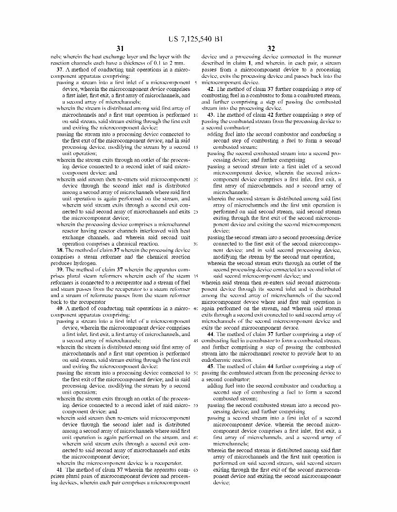
US 7,125,540 Bl 31 32
nels; wherein the heat exchange layer and the layer with the reaction channels each have a thickness of 0.1 to 2 mm.
37. A method of conducting unit operations in a micro-component apparatus comprising:
passing a stream into a first inlet of a microcomponent 5 device, wherein the microcomponent device comprises a first inlet, first exit, a first array of microchannels, and a second array of microchannels;
wherein the stream is distributed among said first array of microchannels and a first unit operation is performed 10 on said stream, said stream exiting through the first exit and exiting the microcomponent device;
passing the stream into a processing device connected to the first exit of the microcomponent device; and in said processing device, modifying the stream by a second 15 unit operation;
wherein the stream exits through an outlet of the processing device connected to a second inlet of said micro-component device; and
wherein said stream then re-enters said microcomponent 20 device through the second inlet and is distributed among a second array of microchannels where said first unit operation is again performed on the stream, and wherein said stream exits through a second exit connected to said second array of microchannels and exits 25 the microcomponent device;
wherein the processing device comprises a microchannel reactor having reactor channels interleaved with heat exchange channels, and wherein said second unit operation comprises a chemical reaction. 30
38. The method of claim 37 wherein the processing device comprises a steam reformer and the chemical reaction produces hydrogen.
39. The method of claim 37 wherein the apparatus comprises plural steam reformers wherein each of the steam 35 reformers is connected to a recuperator and a stream of fuel and steam passes from the recuperator to a steam reformer and a stream of reformate passes from the steam reformer back to the recuperator.
40. A method of conducting unit operations in a micro- 40 component apparatus comprising:
passing a stream into a first inlet of a microcomponent device, wherein the microcomponent device comprises a first inlet, first exit, a first array of microchannels, and a second array of microchannels; 45
wherein the stream is distributed among said first array of microchannels and a first unit operation is performed on said stream, said stream exiting through the first exit and exiting the microcomponent device;
passing the stream into a processing device connected to 50 the first exit of the microcomponent device; and in said processing device, modifying the stream by a second unit operation;
wherein the stream exits through an outlet of the processing device connected to a second inlet of said micro- 55 component device; and
wherein said stream then re-enters said microcomponent device through the second inlet and is distributed among a second array of microchannels where said first unit operation is again performed on the stream, and 60 wherein said stream exits through a second exit connected to said second array of microchannels and exits the microcomponent device;
wherein the microcomponent device is a recuperator. 41. The method of claim 37 wherein the apparatus com- 65
prises plural pairs of microcomponent devices and processing devices, wherein each pair comprises a microcomponent
device and a processing device connected in the manner described in claim 1, and wherein, in each pair, a stream passes from a microcomponent device to a processing device, exits the processing device and passes back into the microcomponent device.
42. The method of claim 37 further comprising a step of combusting fuel in a combustor to form a combusted stream, and further comprising a step of passing the combusted stream into the processing device.
43. The method of claim 42 further comprising a step of passing the combusted stream from the processing device to a second combustor;
adding fuel into the second combustor and conducting a second step of combusting a fuel to form a second combusted stream;
passing the second combusted stream into a second processing device; and further comprising
passing a second stream into a first inlet of a second microcomponent device, wherein the second micro-component device comprises a first inlet, first exit, a first array of microchannels, and a second array of microchannels;
wherein the second stream is distributed among said first array of microchannels and the first unit operation is performed on said second stream, said second stream exiting through the first exit of the second microcomponent device and exiting the second microcomponent device;
passing the second stream into a second processing device connected to the first exit of the second microcomponent device; and in said second processing device, modifying the stream by the second unit operation;
wherein the second stream exits through an outlet of the second processing device connected to a second inlet of said second microcomponent device; and
wherein said stream then re-enters said second microcomponent device through its second inlet and is distributed among the second array of microchannels of the second microcomponent device where said first unit operation is again performed on the stream, and wherein said stream exits through a second exit connected to said second array of microchannels of the second microcomponent device and exits the second microcomponent device.
44. The method of claim 37 further comprising a step of combusting fuel in a combustor to form a combusted stream, and further comprising a step of passing the combusted stream into the microchannel reactor to provide heat to an endothermic reaction.
45. The method of claim 44 further comprising a step of passing the combusted stream from the processing device to a second combustor;
adding fuel into the second combustor and conducting a second step of combusting a fuel to form a second combusted stream;
passing the second combusted stream into a second processing device; and further comprising
passing a second stream into a first inlet of a second microcomponent device, wherein the second micro-component device comprises a first inlet, first exit, a first array of microchannels, and a second array of microchannels;
wherein the second stream is distributed among said first array of microchannels and the first unit operation is performed on said second stream, said second stream exiting through the first exit of the second microcomponent device and exiting the second microcomponent device;

US 7,125,540 Bl 33 34
passing the second stream into a second processing device connected to the first exit of the second microcompo-nent device; and in said second processing device, modifying the stream by the second unit operation;
wherein the second stream exits through an outlet of the 5 second processing device connected to a second inlet of said second microcomponent device; and
wherein said stream then re-enters said second microcomponent device through its second inlet and is distributed among the second array of microchannels of the second 10 microcomponent device where said first unit operation is again performed on the stream, and wherein said stream exits through a second exit connected to said second array of microchannels of the second microcomponent device and exits the second microcomponent device. 15
46. The microchannel device of claim 2 wherein the heat exchanger has an exergetic efficiency of at least 85% when the first zone is at a temperature of 600° C. and the second zone has a temperature of 200° C.
47. A method of conducting unit operations in a micro- 20 channel device comprising: performing at least one unit process operation in a first zone at a first temperature; performing at least one unit process operation in a second zone at a second temperature; 25 wherein the first temperature is different than the second temperature; and wherein a microchannel heat exchanger is disposed between the first zone and the second zone; and wherein a stream flows from the second zone through the 30 microchannel heat exchanger to the first zone and subsequently flows back through the microchannel heat exchanger to the second zone; wherein within the microchannel heat exchanger, heat is exchanged between the stream flowing from the second zone 35 to the first zone and the stream flowing from the first zone to the second zone; and wherein the heat exchanger has a thermal power density of at least 0.6 W per cubic centimeter and an exergetic efficiency of at least 80%. 40
48. The method of claim 47 wherein the first zone comprises a chemical reactor.
49. The method of claim 48 wherein the temperature of the first zone and the temperature of the second zone differ by at least 350° C. 45
50. The micro structure architecture of claim 9 wherein the first unit operation comprises heating reactants; the second unit operation comprises vaporizing a fuel; and the third unit operation comprises heating water.
51. The micro structure architecture of claim 6 wherein 50 each of the layers has a thickness of between 0.1 and 1 mm.
52. The micro structure architecture of claim 9 wherein each of the layers has a thickness of between 0.1 and 1 mm.
53. The microstructure architecture of claim 6 comprising at least three layers with a fuel vaporizer and at least two 55 heat exchanger layers.
54. The process of claim 24 comprising a first stage and a second stage, wherein the first stage and the second stage contain the same unit operations; and
wherein the first stage contains a number, n, of plural cells 60 operating in parallel, and
wherein the second stage accomplishes a separation with fewer cells operating in parallel.
55. A method of conducting unit operations in microcomponent apparatus comprising: 65
performing a first unit operation on a first stream in a first microcomponent cell, subsequent to the first unit opera
tion, performing a second, discrete unit operation on the first stream to make a first modified stream, then in a second microcomponent cell, performing the first unit operation on the first modified stream, to accomplish a single unit operation for the same purpose as the a first unit operation on the first stream;
wherein the method further comprises passing a second stream through a third microcomponent cell and conducting a third unit operation on the second stream and subsequently passing the second stream into the first microcomponent cell and, simultaneous with the step of performing a first unit operation on a first stream in a first microcomponent cell, performing a unit operation on the second stream in the first microcomponent cell to make a modified second stream;
passing the modified second stream into the third micro-component cell and conducting a unit operation on the modified second stream in the third microcomponent cell;
passing a third stream through a fourth microcomponent cell and conducting the third unit operation on the third stream and subsequently passing the third stream into the second microcomponent cell and, simultaneous with the step of performing a first unit operation on a first modified stream in the second microcomponent cell, performing a unit operation on the third stream in the second microcomponent cell to make a modified third stream; and
passing the modified third stream into the fourth micro-component cell and conducting a unit operation on the modified third stream in the fourth microcomponent cell.
56. The method of claim 55 further comprising: subsequent to the step of performing the first unit opera
tion on the first modified stream, performing the second unit operation on the first modified stream to make a second modified stream.
57. The method of claim 55 wherein the third microcomponent cell comprises a first recuperator and wherein the fourth microcomponent cell comprises a second recuperator;
wherein the unit operation in the first recuperator comprises heat exchange between the second stream and the modified second stream; and
wherein the unit operation in the second recuperator comprises heat exchange between the third stream and the modified third stream.
58. The method of claim 57 wherein the third unit operation comprises heat exchange and wherein the recuperator has a thermal power density of at least 0.6 W per cubic centimeter and an exergetic efficiency of at least 85%.
59. The method of claim 55 where the first stream comprises a heat exchange fluid and the first unit operation in a microcomponent cell comprises heat exchange, with heat being transferred from the first stream to provide heat for an endothermic process;
wherein the second unit operation modifying first stream comprises reheating said first fluid by reheating from a heat source or by adding additional fuel or oxygen and performing combustion reactions.
60. The method of claim 59 where the endothermic process is an endothermic chemical reaction.
61. The method of claim 59 where the endothermic process comprises a drying or desorption process.
62. The method of claim 59 where the endothermic process comprises boiling or evaporation.

US 7,125,540 Bl 35
63. The process of claim 55 where the first stream is comprised of chemical reactants and the first unit operation in a microcomponent cell comprises a chemical conversion reaction;
wherein the second unit operation modifying first stream comprises mass transfer, with at least one original reactant being added to the first stream.
36 64. The process of claim 63 where the chemical reaction
in first unit operation comprises steam reforming of hydrocarbons, and the second unit operation comprises adding additional hydrocarbon reactant to first stream.