(12) united states patent (10) patent no.: us … · us 8,496,854 b2 3 tive is post-crosslinking...
TRANSCRIPT

USOO8496854B2
(12) United States Patent (10) Patent No.: US 8.496,854 B2 Mercy et al. (45) Date of Patent: Jul. 30, 2013
(54) POSITIVE TEMPERATURE COEFFICIENT 6,299,801 B1 * 10/2001 Handa et al. .................. 252/511 MATERALS WITH REDUCED NEGATIVE 6,620,343 B1* 9/2003 Blok et al. .................... 252/511 TEMPERATURE COEFFICIENT EFFECT 7,041.238 B2 5/2006 Kim et al.
8,003,016 B2 * 8/2011 Mercx et al. .................. 252/511 (75) Inventors: Franciscus Petrus Maria Mercx, 2003/0031438 A 2.2003 Kambeet al.
Bergen op Zoom (NL); Sascha Ter 2003/0059366 A1 3/2003 Venigalla et al. Horst. Bergen o Zoom (NL) 2004.0009351 A1 1/2004 Venigalla et al.
, Bergen op 2004/O151892 A1 8, 2004 Holl et al.
(73) Assignee: Sabic Innovative Plastics IP B.V. (NL) FOREIGN PATENT DOCUMENTS ck
(*) Notice: Subject to any disclaimer, the term of this E. oo:: A. 88. patent is extended or adjusted under 35 GB 1457,157 A 12, 1976 U.S.C. 154(b) by 110 days. WO 89.12308 A1 12, 1989
WO 95/O1642 A1 1, 1995 (21) Appl. No.: 12/914,497 WO 96.37543 A1 11, 1996
(22) Filed: Oct. 28, 2010 (Continued)
(65) Prior Publication Data OTHER PUBLICATIONS
US 2011 FO297891 A1 Dec. 8, 2011 Heat Deflection Temperature Testing of Plastics; MatWeb, Material Property Data; http://www.matweb.com/reference/deflection-tem
Related U.S. Application Data perature.aspx. 2 pages (downloaded Jan. 15, 2013).
(60) Provisional application No. 61/256,350, filed on Oct. (Continued) 30, 2009.
(51) Int. Cl. Primary Examiner — Mark Kopec AE (g 388 Assistant Examiner — Jaison Thomas HOB I/04 (2006.015 (74) Attorney, Agent, or Firm — Cantor Colburn LLP HOIC 7/10 (2006.01)
(52) U.S. Cl. USPC ........... 252/500; 252/502; 252/512,338/22R (7) ABSTRACT
(58) Field of Classification Search Positive temperature coefficient (PTC) compositions having USPC . . . . . . . . . . 252/500-5216, 338/22 R a reduced negative temperature coefficient effect (NTC) are See application file for complete search history. provided that are achieved without crosslinking the thermo
(56) References Cited plastic base material. The PTC compositions include a ther
U.S. PATENT DOCUMENTS
4,534,889 A 8/1985 van Konynenburg et al. 4,560.498 A 12/1985 Horsma et al. 4,910,389 A * 3/1990 Sherman et al. .............. 219,548 5,106,538 A 4, 1992 Barma et al.
moplastic base resin, an electrically conductive filler and particles of a polymeric additive dispersed in the PTC com position.
13 Claims, 3 Drawing Sheets
ease
ti-3
is is :::::::::::::::::::::::::
state
is: $x&
i as &
1.E. &
reira state to S3. E.
St.
Sitting :
? s
asperatire

US 8,496,854 B2 Page 2
FOREIGN PATENT DOCUMENTS
WO OO,25325 A1 5, 2000 WO 01.09905 A2 2, 2001 WO 2005048273 A2 5, 2005
OTHER PUBLICATIONS
Dow Amplify (TM) EA 101 Ethylene-ethyl Acrylate (EEA); MatWeb, Material Property Data, www.matweb.com/search, 2 pages (downloaded Jan. 15, 2013). M. Narkis et al.; “Effect of Crosslinking on Carbon Black/Polyeth ylene Switching Materials”, Journal of Applied Polymer Science, 1990, vol. 25, pp. (4). M. Narkis et al.; “Electrical Properties of Carbon Black Filled Crosslinked Polyethylene'. Polymer Engineering and Science, Nov. 1981, vol. 21, No. 16, pp. (6).
Hwan-Man Park et al.: “Exfoliated Graphite Nanoplatelet (xGnP) /Polypropylene Nanocomposites', www.speautomotive. nanocomposites-part2-paper2-park-msu-pdf-d326126.841, 9 pages (downloaded Jan. 15, 2013). L. Rejon et al.; “Percolation Phenomena in Carbon Black-Filled Polymeric Concrete'. Polymer Engineering and Science, Sep. 2000, vol. 40, No. 9, pp. (4). Weihua Diet al.; "Positive-Temperature-Coefficient/Negative-Tem perature-Coefficient Effect of Low-Density Polyehtylene Filled with a Mixture of Carbon Black and Carbon Fiber'. J. Polym Science Part B: Polym Phys. 2003, vol. 21, pp. 3094-3101. M. Narkis et al., “Resistivity Behavior of Filled Electrically Conduc tive Crosslinked Polyethylene'. Journal of Applied Polymer Science, 1984, vol. 29, pp. 1639-1652.
* cited by examiner

U.S. Patent Jul. 30, 2013 Sheet 1 of 3 US 8496,854 B2
HDPE based PTC
Ese -
E. E.
E+ - re" s Normal state switching temp
OE-O is f t
Temperature C
FIG.

U.S. Patent Jul. 30, 2013 Sheet 2 of 3 US 8496,854 B2
100C
wbox
too. 2
f3
100
2 4. s 8. 12 40 6 i8
Temperature C
FIG.2
E8
e
E8
es
E-4
E3
-2
E-1
..}} 2 4. SO 8. 2 4. 8. 8.
Temperature C
FIG 3

U.S. Patent Jul. 30, 2013 Sheet 3 of 3 US 8496,854 B2
OE
OE-03
OEC5
co-off freference) root; 2 (low-NTC)
E-3
100
E-CO O 2 40 60 80 10 2 40 18 8O
Temperature (C)
FIG. 4

US 8,496,854 B2 1.
POSITIVE TEMPERATURE COEFFICIENT MATERALS WITH REDUCED NEGATIVE TEMPERATURE COEFFICIENT EFFECT
CROSS REFERENCE TO RELATED APPLICATIONS
The present application claims priority to U.S. Provisional Patent Application No. 61/256,350 filed Oct. 30, 2009, which is hereby incorporated by reference in its entirety.
FIELD OF THE INVENTION
The present invention relates to positive temperature coef ficient compositions, articles of manufacture that include a positive temperature coefficient composition, and methods of making articles that include a positive temperature coefficient composition. In particular, the present invention relates to positive temperature coefficient compositions that have a reduced negative temperature coefficient effect.
BACKGROUND OF THE INVENTION
It is known that polymers can be made electrically conduc tive by dispersing therein Suitable amounts of conductive particulate fillers such as carbon black or fine metal particles. Over recent years, there has been particular interest in such compositions that exhibit positive temperature coefficient (PTC) characteristics, i.e., which show a very rapid increase in resistivity over a particular temperature range. PTC materials are conductive materials characterized by a
sharp increase in resistivity upon reaching a switching tem perature (Ts). If the jump in resistivity is sufficiently high, the resistivity effectively blocks the current and further heating of the material Such that overheating of the material is pre vented. One of the main benefits of PTC materials is that no additional electronic circuits are necessary in an article that includes a PTC material since the PTC material itself has a characteristic similar to electronic circuits. Moreover, upon cooling, the material resets itself. This jump in resistivity may oftentimes be referred to as the PTC amplitude and may be defined as the ratio of the maximum volume resistivity to the volume resistivity at room temperature (app. 23°C.).
FIG. 1 is an exemplary depiction of the behavior of an electrically conducting polymeric PTC composition when Subjected to a change in temperature. FIG. 1 depicts the changes in electrical resistivity when the material is subjected to a change in temperature. The electrical resistivity increases from the bottom to the top of the y-axis. As can be seen at the Switching temperature T, there is a change in resistivity of several orders of magnitude. The Switching temperature is indicated by the letter (A) in FIG. 1. At temperatures lower than the Switching temperature, the resistivity of the poly meric composition does not change very much with a change in temperature (region 1). The slope of the resistivity curve prior to the switching temperature is referred to in FIG. 1 as the first slope. At temperatures greater than the Switching temperature, there is an increase in the electrical resistivity of several orders of magnitude with temperature (region 2). This is referred to as the second slope. The Switching temperature (A) is defined as the intersection of a tangent taken to the first slope with a tangent taken to the second slope. After the resistivity has increased rapidly with temperature, a maxi mum in resistivity is reached. The PTC amplitude is often defined as the ratio of the maximum volume resistivity to the volume resistivity at room temperature (app. 23°C.). Another way to express the PTC effect is defining the volume resis
10
15
25
30
35
40
45
50
55
60
65
2 tivity at a certain temperatureX divided by the room tempera ture resistivity (R. /R- ). As the temperature is raised further, however, often the electrical resistivity of the poly meric composition drops with temperature (region 3). The electrically conducting polymer composition now displays a negative temperature coefficient of resistance (NTC). This change from PTC behavior to a strong NTC behavior is often undesirable. There have been several theories put forth to explain both the PTC and the NTC effect. Polymeric PTC composites are based on semi-crystalline polymers and con ducting fillers whose concentration is just above the percola tion threshold. The mechanism for the PTC anomaly in semi crystalline polymers is attributed to the relatively large change in specific Volume of the polymer at the onset of melting. Due to this Volume expansion stresses are generated resulting in displacement of part of the conductive fillers thereby disrupting the conductive chains. In addition and due to increased amorphous Volume, the concentration of conduc tive particles effectively decreases. Both factors result in a sharp increase in resistivity. With increasing temperature the mobility of the conductive fillers increase, resulting in a reconnection of the conductive fillers opposing the initial contact loss and PTC effect and leading to a Negative Tem perature Coefficient (NTC) effect on the resistivity. PTC materials have been utilized in self-controlled heaters.
When connected to a power source, the PTC material will heat up to the trip temperature and maintain this temperature without the use of any additional electronic controllers.
Compositions exhibiting PTC behavior have also been used in electrical devices as over-current protection in elec trical circuits comprising a power source and additional elec trical components in series. Under normal operating condi tions in the electrical circuit, the resistance of the load and the PTC device is such that relatively little current flows through the PTC device. Thus, the temperature of the device remains below the critical or trip temperature. If the load is short circuited or the circuit experiences a power Surge, the current flowing through the PTC device increases greatly. At this point, a great deal of power is dissipated in the PTC device. This power dissipation only occurs for a short period of time (fraction of a second), however, because the power dissipa tion will raise the temperature of the PTC device to a value where the resistance of the PTC device has become so high, that the current is limited to a negligible value. The device is said to be in its “tripped' state. The negligible or trickle through current that flows through the circuit will not damage the electrical components which are connected in series with the PTC device. Thus, the PTC device acts as a form of a fuse, reducing the current flow through the short circuit load to a safe, low value when the PTC device is heated to its critical temperature range. Upon interrupting the current in the cir cuit, or removing the condition responsible for the short cir cuit (or power surge), the PTC device will cool down below its critical temperature to its normal operating, low resistance state. The effect is a resettable, electrical circuit protection device.
Various materials have been developed that show these characteristics. Among them are ceramics as well as polymer based PTC materials. One problem is that most PTC materials exhibit Negative Temperature Coefficient (NTC) characteris tics immediately after the PTC characteristics. If the jump in resistivity is not sufficiently high or if the NTC effect is pronounced it means that current can start to flow again. This is unwanted and efforts have been undertaken to reduce or eliminate the NTC effect.
In polymeric PTC materials reduction of the NTC effect has been achieved by cross-linking the material. Most effec

US 8,496,854 B2 3
tive is post-crosslinking after the forming step either by gamma radiation or accelerated electrons. Cross-linking in the melt also erases the NTC effect but negatively affects the PTC amplitude. In addition, the step of cross-linking the material increases the time and production costs for manu facturing the PTC material.
Accordingly, it would be beneficial to provide a PTC mate rial that has a reduced negative temperature coefficient effect as compared to prior artPTC materials to help reduce some of the disadvantages associated with prior art materials. It would also be beneficial to provide a PTC material that has a reduced negative temperature coefficient effect other than by cross linking of the material.
BRIEF SUMMARY OF THE INVENTION
The present invention addresses the issues associated with the prior art by providing a positive temperature coefficient (PTC) material that has a reduced negative temperature coef ficient (NTC) effect. The compositions of the present inven tion include a thermoplastic polymer, and at least one con ductive filler. The conductive filler might be carbon black, graphite, metal fillers or conductive ceramics or combina tions of these. The compositions of the present invention may also include one or more additives to improve select charac teristics of the PTC compositions such that they may be used in a wide variety of applications. The PTC compositions of the present invention permit PTC materials to be designed that can be tailored to operate at different temperatures based upon the thermoplastic polymer used.
Accordingly, in one aspect, the present invention provides a positive temperature coefficient material having from 20 to 90% by weight of a thermoplastic polymer, from 10 to 60% by weight of at least one conductive filler; and from 0.1 to 20% by weight of a polymer additive; wherein the polymer additive has a melting or softening temperature greater than the melting temperature of the thermoplastic resin; wherein the polymer additive is dispersed in the positive temperature coefficient composition.
Accordingly, in one aspect, the present invention provides a positive temperature coefficient material having from 20 to 90% by weight of a thermoplastic polymer, from 10 to 60% by weight of at least one conductive filler; and from 0.1 to 20% by weight of a polymer additive; wherein the higher melting or softening temperature polymer additive has <50, 000 monomer units; wherein the polymer additive is dis persed in the positive temperature coefficient composition.
In another aspect, the present invention provides a method of making a positive temperature coefficient composition including the steps of mixing from 10 to 60% by weight of at least one conductive filler with from 20 to 90% by weight of a thermoplastic polymer; and dispersing from 0.1 to 20% by weight of a polymer additive into the positive temperature coefficient composition; wherein the polymer additive has a melting or softening temperature greater than the melting temperature of the thermoplastic resin and wherein the poly mer additive is dispersed in the positive temperature coeffi cient composition.
BACKGROUND OF THE INVENTION
FIG. 1 shows a typical example of the resistivity of poly meric PTC materials as a function of temperature
FIG.2 shows the resistivity as a function oftemperature for several embodiments made according to the concepts of the present invention as compared to a prior art PTC material.
10
15
25
30
35
40
45
50
55
60
65
4 FIG.3 shows the resistivity as a function oftemperature for
several embodiments made according to the concepts of the present invention as compared to a prior art PTC material.
FIG. 4 shows the resistivity as a function oftemperature for several embodiments made according to the concepts of the present invention as compared to a prior art PTC material
DETAILED DESCRIPTION OF THE INVENTION
The present invention is more particularly described in the following description and examples that are intended to be illustrative only since numerous modifications and variations therein will be apparent to those skilled in the art. As used in the specification and in the claims, the term "comprising may include the embodiments "consisting of and “consist ing essentially of All ranges disclosed hereinare inclusive of the endpoints and are independently combinable. The end points of the ranges and any values disclosed herein are not limited to the precise range or value; they are Sufficiently imprecise to include values approximating these ranges and/ or values. As used herein, approximating language may be applied to
modify any quantitative representation that may vary without resulting in a change in the basic function to which it is related. Accordingly, a value modified by a term or terms, such as “about and “substantially, may not be limited to the precise value specified, in some cases. In at least some instances, the approximating language may correspond to the precision of an instrument for measuring the value. The present invention provides positive temperature coef
ficient (PTC) materials, articles of manufacture that include one or more positive temperature coefficient materials, and methods of making articles that include one or more positive temperature coefficient materials. The PTC materials of the present invention have a reduced negative temperature coef ficient effect (NTC) as compared to prior art PTC materials. As a result, the resistivity of the material does not quickly drop once the peak melting temperature of the thermoplastic base resin is reached. This effect is achieved through the use of particles of a polymeric additive that are dispersed in the PTC composition.
Accordingly, in one embodiment, the PTC compositions of the present invention provide a composition having PTC characteristics that includes a thermoplastic base resin and an electrically conductive filler. The PTC compositions of the present invention also have a reduced NTC effect achieved through the addition of particles of a polymeric additive dis persed in the PTC composition. The resulting composition is therefore capable of having a reduced NTC effect without the need for cross-linking of the thermoplastic material, which is required by prior art PTC compositions, to achieve this reduced NTC effect. Additional additives may also be used to provide additional characteristics in alternative embodi mentS. As such, in one aspect, the thermoplastic compositions of
the present invention use a semi-crystalline thermoplastic resin as the base for the composition. Examples of thermo plastic resins that may be used in the present invention include, but are not limited to, polyethylene (PE), including high-density polyethylene (HDPE), linear low-density poly ethylene (LLDPE), low-density polyethylene (LDPE), mid density polyethylene (MDPE), maleic anhydride functional ized polyethylene, maleic anhydride functionalized elastomeric ethylene copolymers (like EXXELORVA1801 and VA1803 from ExxonMobil), ethylene-butene copoly mers, ethylene-octene copolymers, ethylene-acrylate copoly mers like ethylene-methyl acrylate, ethyelene-ethyl acrylate

US 8,496,854 B2 5
and ethylene butyl acrylate copolymers, glycidyl methacry late modified polyethylene, polypropylene (PP), maleic anhydride functionalized polypropylene, glycidyl methacry late modified polypropylene, polyvinyl chloride (PVC), poly vinyl acetate, polyvinyl acetyl, acrylic resin, syndiotactic 5 polystyrene (sPS), polyphenylene-sulfide (PPS), polyamide imide, polyimide, polyketones like polyetheretherketone (PEEK), polyetherketone (PEK), polyethylene vinyl acetate (EVA), glycidyl methacrylate modified polyethylene vinyl acetate, polyvinylalcohol, polyisobutylene, poly(vinylidene chloride), poly(vinylidene fluoride) (PVDF), poly(methy lacrylate), polyacrylonitrile, polybutadiene, polyesters like polyethylene-terephthalate (PET), polybutylene-terephtha late (PBT), poly(8-aminocaprylic acid), poly(vinyl alcohol) (PVA), polycaprolactone, polyamides like PA6, PA66, PA6, 10, PA11 and PA12, polyphthalamide (PPA), high tempera ture nylon (HTN) or blends, mixtures or combinations of one or more of these polymers. In beneficial embodiments of the present invention, the thermoplastic polymer is a polyethyl ene polymer, Such as high-density polyethylene. As used herein, a “high-density polyethylene' has a density greater than 0.94 g/cm. Thermosets can also be used, but most embodiments utilize thermoplastic material. The amount of the thermoplastic resin used may vary
depending on the presence and/or amount of other fillers as well as the type of fillers and/or polymeric additive used. In one embodiment, the thermoplastic resin is present in an amount from 20% to 90% by weight of the total weight of the composition. In an alternative embodiment, the thermoplastic resin is present in an amount from 30% to 80% by weight of the total weight of the composition.
In addition to the thermoplastic resin, the compositions of the present invention also include an electrically conducting filler. The conductive filler can include at least one ceramic filler, at least one metallic filler, at least one carbon-contain- 35 ing filler or a combination including at least one of the fore going fillers. The electrically conducting filler may exist in the form of spheres, flakes, fibers, whiskers, or the like, or a combination including at least one of the foregoing forms. These electrically conducting filler may have cross-sectional 40 geometries that may be circular, ellipsoidal, triangular, rect angular, polygonal, or a combination including at least one of the foregoing geometries. The electrically conducting filler, as commercially available, may exist in the form of aggre gates or agglomerates prior to incorporation into the PTC composition or even after incorporation into the PTC com position. An aggregate includes more than one filler particle in physical contact with one another, while an agglomerate includes more than one aggregate in physical contact with one another. As discussed, the electrically conducting filler is electri
cally conducting. Accordingly, in one embodiment, the elec trically conducting filler has an electrical resistivity of 1 to 1x10⁷ microohm-cm. In another embodiment, the electrically conducting filler has an electrical resistivity of 10-10' microohm-cm. In yet another embodiment, the electrically conducting filler has an electrical resistivity of 10°-10 microohm-cm.
Conductive fillers include carbonaceous fillers such as for example carbon black, carbon nanotubes, carbon fibers and graphite, or the like, or a combination including at least one of the foregoing carbonaceous fillers. Carbon blackhaving aver age particle sizes of less than or equal to 200 nm are benefi cial. In one embodiment, the carbon black has an average particle sizes of less than or equal to 100 nm can be used. In another embodiment, the carbon black has an average particle sizes of greater than or equal to 40 nm can be used. Carbon
10
15
25
30
45
50
55
60
65
6 nanotubes can include single wall carbon nanotubes, multi wall carbon nanotubes, or the like. The carbon nanotubes generally have aspect ratios of greater than or equal to 2. In one embodiment, the carbon nanotubes have aspect ratios of greater than or equal to 100. In another embodiment, the carbon nanotubes have aspect ratios of greater than or equal to 1,000. The carbon nanotubes have diameters of 2 nm to 500 nm. In one embodiment, the carbon nanotubes have diameters of 5 nm to 100 nm. In one embodiment, the carbon nanotubes have diameters of 7 nm to 30 nm. Graphite fibers are generally obtained from the pyrolysis of pitch or polyacrylonitrile (PAN) based fibers. Graphite fibers having diameters of 1 micrometer to 30 micrometers and lengths of 0.5 millimeter to 2 centimeters can be used in the electrically conducting polymer composition.
Examples of suitable ceramic fillers are metal oxides, metal carbides, metal nitrides, metal hydroxides, metal oxides having hydroxide coatings, metal carbonitrides, metal oxynitrides, metal borides, metal borocarbides, or the like, or a combination including at least one of the foregoing inor ganic materials. Metal cations in the foregoing ceramic fillers can be transition metals, alkali metals, alkaline earth metals, rare earth metals, or the like, or a combination including at least one of the foregoing metal cations.
Examples of Suitable electrically conducting ceramic fill ers are titanium diborides (TiB) tungsten carbide (WC), tin oxide, indium tin oxide (ITO), antimony tin oxide, titanium nitride (TiN), Zirconium nitride (ZrN), titanium carbide (TiC), molybdenum silicide (MoSi.), potassium titanate whiskers, Vanadium oxides (VO), or a combination includ ing at least one of the foregoing ceramic fillers.
"Metallic fillers' include metal powders, metal-coated par ticles, or any other conductive, metal-containing particles. Examples of suitable metal powders include tool steels, mar tensitic stainless steel, high-speed tool steels, stainless steel, iron, silicone chromium, silver, Vanadium, tungsten, nickel, or the like, or a combination including at least one of the foregoing metals. Metal alloys can also be added to the elec trically conducting polymer composition. Examples of metal alloys include tool steel, martensitic stainless steel stainless steel, neodymium iron boron (NdFeB), samarium cobalt (SmCo), aluminum nickel cobalt (AlNiCo), or the like, or a combination including at least one of the foregoing. Examples of metal-coated particles include conductive or non-conductive Substrates coated with a layer of Solid con ductive metal such as aluminum, copper, magnesium, chro mium, tin, nickel, silver, iron, titanium, or the like, or a combination including at least one of the foregoing metals may be used to coat the Substrates. The electrically conducting filler can be nanoparticles or
micrometer sized particles. If the electrically conducting filler is nanoparticles it is beneficial to have an average par ticle size of less than or equal to 500 nm. In one embodiment, it is beneficial for the average particle size to be less than or equal to 200 nm. In another embodiment, it is beneficial for the average particle size to be less than or equal to 100 nm. In yet another embodiment, it is beneficial for the average par ticle size to be less than or equal to 50 nm.
If the electrically conducting filler is micrometer-sized par ticles then it is beneficial to have an average particle size of greater than or equal to 1 micrometer (Lm). In another embodiment, it is beneficial for the average particle size to be greater than or equal to 5um. In yet another embodiment, it is beneficial for the average particle size to be greater than or equal to 10um. In another embodiment, it is beneficial for the particle sizes to be greater than or equal to 100 Lum.

US 8,496,854 B2 7
The amount of the conductive filler used may vary depend ing on the presence and/or amount of other fillers as well as the type of thermoplastic resin and/or polymeric additive used. In one embodiment, the conductive filler is present in an amount from 10% to 60% by weight of the total weight of the composition. In an alternative embodiment, the conductive filler is present in an amount from 15% to 50% by weight of the total weight of the composition.
In addition to the thermoplastic polymer and the electri cally conductive filler, the compositions of the present inven tion include a polymeric additive that helps to reduce the NTC effect associated with prior art PTC compositions. The poly meric additive is selected such that it is capable of being dispersed in the PTC composition and the polymeric additive is chosen Such that it has a higher melting or softening tem perature than the melting temperature of the thermoplastic polymer of the PTC composition. Not wishing to be bound by theory, it is believed that that polymeric additive helps reduce the NTC effect in a PTC composition as the dispersed poly meric additive particles act as a solid filler at and above the PTC trip temperature thereby increasing the viscosity and limiting the mobility of the conductive fillers in the thermo plastic polymer phase thereby preventing the re-organization of the conductive fillers which is believed to be responsible for the NTC effect observed in prior art PTC materials.
Accordingly, the polymeric additive is selected from any polymer capable of being dispersed in particles within another thermoplastic material. The polymeric additive is selected Such that it has a melting or softening temperature above the melting temperature of the thermoplastic polymer of the PTC composition such that the polymeric additive remains substantially in particle form and/or does not blend with the thermoplastic polymer. In one embodiment, the polymeric additive has a melting or softening temperature 10° C. or more than the melting temperature of the thermoplastic polymer of the PTC composition. In another embodiment, the polymeric additive has a melting or softening temperature 20° C. or more than the melting point of the thermoplastic poly mer of the PTC composition. Examples of polymeric addi tives that may be used in the present invention include, but are not limited to, polyamide. Such as nylon 6 or nylon 66, high temperature nylons, polyphthalamide, polyphenylene Sul fide, polyesters, polyketones, polyimides, polysulfones, polycarbonate, polyphenylene ether, polyether imide, etc. The polymer additive selected typically has less than
50,000 monomer units. In one embodiment, the polymer additive has less than 10,000 monomer units. In another embodiment, the polymer additive has less than 1,000 mono mer units. In yet another embodiment, the polymer additive has greater than 50 monomer units When processed at tem peratures above the melting temperatures of this polymer additive, the overall viscosity is low enough to be able to injection molded and in fact even thin-walled molding is feasible (e.g. walls having a thickness of <1 mm). At the processing temperature the composition has a sufficiently low viscosity to be able to injection molded, but at the same time the mobility at the trip temperature and above is reduced, as the polymers added are still solid particles thereby obstruct ing the local mobility of the base resin chains.
In one embodiment, polyamides may be used as the poly meric additive in the PTC composition. Polyamides are gen erally derived from the polymerization of organic lactams
5
10
15
25
30
35
40
45
50
55
60
65
8 having from 4 to 12 carbon atoms. Exemplary lactams are represented by the formula (I)
(I)
(CH2), H1N1
wherein n is about 3 to about 11. In one embodiment the lactam is epsilon-caprolactam having n equal to 5.
Polyamides may also be synthesized from amino acids having from 4 to 12 carbonatoms. Exemplary amino acids are represented by the formula (II)
(II) O
wherein n is about 3 to about 11. In one embodiment the amino acid is epsilon-aminocaproic acid with n equal to 5.
Polyamides may also be polymerized from aliphatic dicar boxylic acids having from 4 to 12 carbon atoms and aliphatic diamines having from 2 to 12 carbonatoms. Suitable aliphatic dicarboxylic acids are the same as those described above for the synthesis of polyesters hereinafter. Exemplary aliphatic diamines are represented by the formula (III)
H2N-(CH2). NH2 (III) wherein n is about 2 to about 12. In one embodiment the aliphatic diamine is hexamethylenediamine (H2NCCH) NH). It is beneficial that the molar ratio of the dicarboxylic acid to the diamine be about 0.66 to about 1.5. Within this range it is generally beneficial to have the molar ratio be greater than or equal to about 0.81 in one embodiment and greater than or equal to about 0.96 in another embodiment. Also beneficial within this range is an amount of less than or equal to 1.22 in one embodiment and less than or equal to about 1.04 in another embodiment. Polyamides especially useful in the present invention include, but are not limited to, nylon 6, nylon 6.6, nylon 4.6, nylon 6, 12, nylon 10, or the like, or combinations comprising at least one of the foregoing polyamides.
In another embodiment, cycloaliphatic polyesters may be used as the polymeric additive in the PTC composition. Cycloaliphatic polyesters are generally prepared by reaction of organic polymer precursors such as a diol with a dibasic acid or derivative. The diols useful in the preparation of the cycloaliphatic polyester polymers are straight chain, branched, or cycloaliphatic, preferably straight chain or branched alkane diols, and may contain from 2 to 12 carbon atOmS.
Suitable examples of diols include ethylene glycol, propy lene glycol, i.e., 1.2- and 1,3-propylene glycol; butane diol. i.e., 1.3- and 1,4-butanediol; diethylene glycol, 2,2-dimethyl 1,3-propane diol, 2-ethyl, 2-methyl, 1,3-propane diol. 1.3- and 1.5-pentane diol, dipropylene glycol, 2-methyl-1,5-pen tane diol. 1,6-hexane diol. 1,4-cyclohexane dimethanol and particularly its cis- and trans-isomers, triethylene glycol, 1,10-decane diol, and mixtures of any of the foregoing. Par ticularly preferred is dimethanol bicyclooctane, dimethanol decalin, a cycloaliphatic diol or chemical equivalents thereof and particularly 1.4-cyclohexane dimethanol or its chemical equivalents. If 1,4-cyclohexane dimethanol is to be used as

US 8,496,854 B2
the diol component, it is generally preferred to use a mixture of cis- to trans-isomers in mole ratios of about 1:4 to about 4:1. Within this range, it is generally desired to use a mole ratio of cis- to trans-isomers of about 1:3. The diacids useful in the preparation of the cycloaliphatic
polyesterpolymers arealiphatic diacids that include carboxy lic acids having two carboxyl groups each of which are attached to a Saturated carbon in a Saturated ring. Suitable examples of cycloaliphatic acids include decahydro naphtha lene dicarboxylic acid, norbornene dicarboxylic acids, bicy clooctanedicarboxylic acids. Preferred cycloaliphatic diac ids are 1,4-cyclohexanedicarboxylic acid and trans-1,4- cyclohexanedicarboxylic acids. Linear aliphatic diacids are also useful when the polyester has at least one monomer containing a cycloaliphatic ring. Illustrative examples of lin ear aliphatic diacids are Succinic acid, adipic acid, dimethyl Succinic acid, and azelaic acid. Mixtures of diacid and diols may also be used to make the cycloaliphatic polyesters.
Cyclohexanedicarboxylic acids and their chemical equiva lents can be prepared, for example, by the hydrogenation of cycloaromatic diacids and corresponding derivatives Such as isophthalic acid, terephthalic acid or naphthalenic acid in a Suitable solvent, water oracetic acid at room temperature and at atmospheric pressure using Suitable catalysts such as rhodium Supported on a suitable carrier of carbon or alumina. They may also be prepared by the use of an inert liquid medium wherein an acid is at least partially soluble under reaction conditions and a catalyst of palladium or ruthenium in carbon or silica is used.
Typically, during hydrogenation, two or more isomers are obtained wherein the carboxylic acid groups are in either the cis- or trans-positions. The cis- and trans-isomers can be separated by crystallization with or without a solvent, for example, n-heptane, or by distillation. While the cis-isomer tends to blend better, the trans-isomer has higher melting and crystallization temperature and is generally preferred. Mix tures of the cis- and trans-isomers may also be used, and preferably when such a mixture is used, the trans-isomer will preferably include at least about 75 wt % and the cis-isomer will include the remainder based on the total weight of cis and trans-isomers combined. When a mixture of isomers or more than one diacid is used, a copolyester or a mixture of two polyesters may be used as the cycloaliphatic polyester resin.
Chemical equivalents of these diacids including esters may also be used in the preparation of the cycloaliphatic polyes ters. Suitable examples of the chemical equivalents of the diacids are alkyl esters, e.g., dialkyl esters, diaryl esters, anhydrides, acid chlorides, acid bromides, or the like, or combinations including at least one of the foregoing chemical equivalents. The preferred chemical equivalents include the dialkyl esters of the cycloaliphatic diacids, and the most pre ferred chemical equivalent includes the dimethyl ester of the acid, particularly dimethyl-trans-1,4-cyclohexanedicarboxy late.
Dimethyl-1,4-cyclohexanedicarboxylate can be obtained by ring hydrogenation of dimethylterephthalate, wherein two isomers having the carboxylic acid groups in the cis- and trans-positions are obtained. The isomers can be separated, the trans-isomer being especially preferred. Mixtures of the isomers may also be used as detailed above. The polyester polymers are generally obtained through the
condensation oresterinterchange polymerization of the poly mer precursors such as diol or diol chemical equivalent com ponent with the diacid or diacid chemical equivalent compo nent and having recurring units of the formula (IV):
10
15
25
30
35
40
45
50
55
60
65
10
(IV)
--O-R-O-Ö-R-C--
wherein R represents an alkyl or cycloalkyl radical contain ing 2 to 12 carbonatoms and which is the residue of a straight chain, branched, or cycloaliphatic alkane diol having 2 to 12 carbon atoms or chemical equivalents thereof; and R is an alkyl or a cycloaliphatic radical which is the decarboxylated residue derived from a diacid, with the proviso that at least one of R or R is a cycloalkyl group. A beneficial cycloaliphatic polyester is poly(1,4-cyclohex
ane-dimethanol-1,4-cyclohexanedicarboxylate) having recurring units of formula (V)
(V)
wherein in the formula (I), R is a cyclohexane ring, and wherein R is a cyclohexane ring derived from cyclohex anedicarboxylate or a chemical equivalent thereof and is selected from the cis- or trans-isomer or a mixture of cis- and trans-isomers thereof. Cycloaliphatic polyester polymers can be generally made in the presence of a suitable catalyst Such as a tetra(2-ethylhexyl)titanate, in a suitable amount, typi cally about 50 to 400 ppm of titanium based upon the total weight of the final product. Aromatic polyesters or polyary lates may also be used in the conductive compositions.
Beneficially, the number average molecular weight of the polyesters is about 3,000 to about 1,000,000 g/mole. Within this range, it is beneficial to have a number average molecular weight of greater than or equal to about 10,000, preferably greater than or equal to about 20,000, and more preferably greater than or equal to about 25,000 g/mole. Also desirable is a number average molecular weight of less than or equal to about 100,000, preferably less than or equal to about 75,000, more preferably less than or equal to about 50,000, and most preferably less than or equal to about 35,000 g/mole. The amount of polymeric additive used in the PTC com
positions is, in one embodiment, from 0.1 to 20 wt.% based on the total weight of the composition. In another embodi ment, the polymeric additive is included in an amount from 1 to 15 wt.% based on the total weight of the composition. In still another embodiment, the polymeric additive is included in an amount from 1 to 10 wt.% based on the total weight of the composition.
In addition to the thermoplastic polymer and the electri cally conductive filler, and the polymeric additive, the com positions of the present invention can include a compatibi lizer. In one embodiment, modified polyolefins may be used as the compatibilizer in the PTC composition. The modified polyolefin may include a polyolefin resin to which an unsat urated monomer containing epoxy, carboxyl, oran acid anhy dride group is copolymerized or grafted. Exemplary epoxy containing unsaturated monomers include glycidyl methacrylate, butylglycidyl malate, butylglycidyl fumarate, propylglycidyl malate, glycidyl acrylate, N-4-(2,3-ep oxypropoxy)-3,5-dimethylbenzyl-acrylamide, and the like. Among these, beneficial embodiments include glycidyl methacrylate and N-4-(2,3-epoxypropoxy)-3,5-dimethyl

US 8,496,854 B2 11
benzyllacrylamide. Exemplary carboxyl-containing unsatur ated monomers include acrylic acid, methacrylic acid, maleic acid, and the like. Exemplary unsaturated monomers contain ing an acid anhydride group are maleic anhydride, itaconic anhydride, citraconic anhydride, and the like. Beneficial embodiments include acrylic acid and maleic anhydride. The amount of compatibilizer used in the compositions is,
in one embodiment, from 0.1 to 15 wt.% based on the total weight of the composition. In another embodiment, the com patibilizer is included in an amount from 1 to 10 wt.% based on the total weight of the composition. In still another embodiment, the compatibilizer is included in an amount from 1 to 6 wt.% based on the total weight of the composition.
In addition to the foregoing components, the thermoplastic compositions of the present invention further may include, in alternative embodiments, a flame retardant. In some cases it might be beneficial to add expandable graphites as Synergist, permitting a reduction the loading of flame retardant. In one embodiment, the flame retardant is a phosphorus containing flame retardant, for example an organic phosphate and/or an organic compound containing phosphorus-nitrogen bonds. One type of exemplary organic phosphate is an aromatic
phosphate of the formula (GO)P–O, wherein each G is independently an alkyl, cycloalkyl, aryl, alkaryl, or aralkyl group, provided that at least one G is an aromatic group. Two of the G groups may be joined together to provide a cyclic group, for example, diphenyl pentaerythritol diphosphate, which is described by Axelrod in U.S. Pat. No. 4,154,775. Other Suitable aromatic phosphates may be, for example, phenyl bis(dodecyl)phosphate, phenyl bis (neopentyl)phos phate, phenyl bis(3,5,5'-trimethylhexyl)phosphate, ethyl diphenyl phosphate, 2-ethylhexyl di(p-tolyl)phosphate, bis (2-ethylhexyl)p-tolyl phosphate, tritolyl phosphate, bis(2- ethylhexyl)phenylphosphate, tri(nonylphenyl)phosphate, bis (dodecyl)p-tolyl phosphate, dibutyl phenyl phosphate, 2-chloroethyl diphenyl phosphate, p-tolyl bis(2.5.5'-trimeth ylhexyl)phosphate, 2-ethylhexyl diphenyl phosphate, or the like. A specific aromatic phosphate is one in which each G is aromatic, for example, triphenyl phosphate, tricresyl phos phate, isopropylated triphenyl phosphate, and the like.
Di- or polyfunctional aromatic phosphorus-containing compounds are also useful, for example, compounds of the formulas below:
O Han
GO l -( ) OG o G
d \ / pi
Xin
ls)--(). GO-P X / \ | 7 o--OG Xm Xin G2 G2 pi
O
--G G2
O O
Go--o o--G G2 G2
10
15
25
30
35
40
45
50
55
60
65
12 wherein each G' is independently a hydrocarbon having 1 to 30 carbon atoms; each G' is independently a hydrocarbon or hydrocarbon having 1 to 30 carbon atoms; each X is indepen dently a bromine or chlorine; m 0 to 4, and n is 1 to 30. Examples of suitable di- or polyfunctional aromatic phospho rus-containing compounds include resorcinol tetraphenyl diphosphate (RDP), the bis(diphenyl)phosphate of hydro quinone and the bis(diphenyl)phosphate of bisphenol-A (, respectively, their oligomeric and polymeric counterparts, and the like. Methods for the preparation of the aforemen tioned di- or polyfunctional aromatic compounds are described in British Patent No. 2,043,083.
Other useful phosphorus containing compounds are the inorganic salts of polyphosphoric acid and ammonia, ammo nium polyphosphate (APP) or polyphosphoric acid and melamine, melamine polyphosphate (MPP). The amount of flame retardant added to the thermoplastic
compositions of the present invention may be based on the type of resin, the type and/or amount of the unmodified poly olefin, the type and/or amount of the modified polyolefin, and/or the type and/or amount of any additional fillers or additives. Accordingly, in the present invention, the amount of flame retardant in the thermoplastic composition is suffi cient to impart flame retardant characteristics while still maintaining a selected impact strength and/or HDT. In one embodiment, the flame retardant is added in amounts up to 30 wt.%. In another embodiment, the flame retardant is added in amounts up to 20 wt.%. In still another embodiment, the flame retardant is added in amounts up to 10 wt.%.
Optionally, inorganic flame retardants may also be used, for example Sulfonate salts such as potassium perfluorobu tane sulfonate (Rimar salt) and potassium diphenylsulfone Sulfonate; salts formed by reacting for example an alkali metal or alkaline earth metal (preferably lithium, sodium, potassium, magnesium, calcium and barium salts) and an inorganic acid complex salt, for example, an oxo-anion, Such as alkali metal and alkaline-earth metal salts of carbonic acid, such as NaCO, KCO, MgCO, CaCO, BaCO, and BaCO or fluoro-anion complex Such as LiAlF, BaSiF. KBF. KAIF. KAIF, KSiF, and/or NaAlF or the like. When present, inorganic flame retardant salts are generally present in amounts of from 0.01 to 1.0 parts by weight, more specifically from 0.05 to 0.5 parts by weight, based on 100 parts by weight of resin, the lubricant, and the flame retardant.
In alternative embodiment, the compositions of the present invention may include one or more fillers. These fillers may be selected to impart additional impact strength and/or pro vide additional characteristics that may be based on the final selected characteristics of the thermoplastic compositions. Suitable fillers or reinforcing agents include, for example, TiO2; fibers, such as glass fibers, carbon fibers, or the like: silicates and silica powders, such as aluminum silicate (mul lite), boehmite (aluminium oxide hydroxide) in the form of needles or powders, synthetic calcium silicate, Zirconium silicate, fused silica, crystalline silica graphite, natural silica sand, or the like; boron powders such as boron-nitride pow der, boron-silicate powders, or the like: alumina; magnesium oxide (magnesia); magnesium hydroxide; calcium sulfate (as its anhydride, dihydrate or trihydrate); calcium carbonates Such as chalk, limestone, marble, synthetic precipitated cal cium carbonates, or the like; talc, including fibrous, modular, needle shaped, lamellartalc, or the like; Wollastonite; surface treated Wollastonite; glass spheres such as hollow and solid glass spheres, silicate spheres, aluminosilicate (armo spheres), or the like; kaolin, including hard kaolin, soft kaolin, calcined kaolin, kaolin including various coatings known in the art to facilitate compatibility with the polymeric

US 8,496,854 B2 13
matrix resin, or the like; single crystal fibers or “whiskers' Such as silicon carbide, alumina, boron carbide, iron, nickel, copper, or the like; glass fibers, (including continuous and chopped fibers), such as E, A, C, ECR, R, S, D, and NEglasses and quartz, or the like: Sulfides such as molybdenum sulfide, Zinc sulfide or the like; barium compounds such as barium titanate, barium ferrite, barium sulfate, heavy spar, or the like; metals and metal oxides such as particulate or fibrous alumi num, bronze, Zinc, copper and nickel or the like; flaked fillers Such as glass flakes, flaked silicon carbide, aluminum diboride, aluminum flakes, steel flakes or the like; fibrous fillers, for example short inorganic fibers such as those derived from blends including at least one of aluminum sili cates, aluminum oxides, magnesium oxides, and calcium Sul fate hemihydrate or the like: natural fillers and reinforce ments, such as wood flour obtained by pulverizing wood, fibrous products such as cellulose, cotton, sisal, jute, starch, cork flour, lignin, ground nut shells, corn, rice grain husks or the like; reinforcing organic fibrous fillers formed from organic polymers capable of forming fibers such as poly(ether ketone), polyimide, polybenzoxazole, poly(phenylene Sul fide), polyesters, polyethylene, aromatic polyamides, aro matic polyimides, polyetherimides, polytetrafluoroethylene, acrylic resins, poly(vinyl alcohol) or the like; as well as addi tional fillers and reinforcing agents such as mica, clay, feld spar, flue dust, fillite, quartz, quartzite, perlite, tripoli, diato maceous earth, or the like, or combinations including at least one of the foregoing fillers or reinforcing agents. The fillers and reinforcing agents may be surface treated
with silanes, titanates, Zirconates to improve adhesion and dispersion with the polymeric matrix resin. In addition, the fillers may be provided in the form of monofilament or mul tifilament fibers and may be used either alone or in combina tion with other types of fiber, through, for example, co-weav ing or core/sheath, side-by-side, orange-type or matrix and fibril constructions, or by other methods known to one skilled in the art of fiber manufacture. Suitable co woven structures include, for example, aromatic polyimide fiberglass fiber or the like. Fibrous fillers may be supplied in the form of, for example, rovings, woven fibrous reinforcements, such as 0-90 degree fabrics or the like: non-woven fibrous reinforce ments such as continuous strand mat, chopped strand mat, tissues, papers and felts or the like; or three-dimensional reinforcements such as braids. Fillers are generally used in amounts of from 1 to 50 parts by weight, based on 100 parts by weight of the total composition.
Lastly, the compositions of the present invention may, in alternative embodiments, include one or more additives ordi narily incorporated in resin compositions of this type. Mix tures of additives may be used. Such additives may be mixed at a Suitable time during the mixing of the components for forming the composition. The one or more additives are included in the thermoplastic compositions to impart one or more selected characteristics to the thermoplastic composi tions and any molded article made therefrom. Examples of additives that may be included in the present invention include, but are not limited to, heat stabilizers, process stabi lizers, antioxidants, light stabilizers, plasticizers, antistatic agents, mold releasing agents, UV absorbers, pigments, dyes, colorants, flow promoters, dispersing agents or a combination of one or more of the foregoing additives.
Suitable heat stabilizers include, for example, organo phosphites such as triphenyl phosphite, tris-(2,6-dimeth ylphenyl)phosphite, tris-(mixed mono- and di-nonylphenyl) phosphite or the like; phosphonates Such as dimethylbenzene phosphonate or the like, phosphates such as trimethyl phos phate, or the like, or combinations including at least one of the
10
15
25
30
35
40
45
50
55
60
65
14 foregoing heat Stabilizers. Heat stabilizers are generally used in amounts of from 0.01 to 0.5 parts by weight based on 100 parts by weight of the total composition, excluding any filler.
Suitable antioxidants include, for example, organophos phites Such as tris(nonyl phenyl)phosphite, tris(2,4-di-t-bu tylphenyl)phosphite, bis(2,4-di-t-butylphenyl)pentaerythri tol diphosphite, distearyl pentaerythritol diphosphite or the like: alkylated monophenols or polyphenols; alkylated reac tion products of polyphenols with dienes, such as tetrakis methylene(3,5-di-tert-butyl-4-hydroxyhydrocinnamate) methane, or the like; butylated reaction products of para cresol or dicyclopentadiene; alkylated hydroquinones; hydroxylated thiodiphenyl ethers; alkylidene-bisphenols: benzyl compounds; esters of beta-(3,5-di-tert-butyl-4-hy droxyphenyl)-propionic acid with monohydric or polyhydric alcohols; esters of beta-(5-tert-butyl-4-hydroxy-3-meth ylphenyl)-propionic acid with monohydric or polyhydric alcohols; esters of thioalkyl or thioaryl compounds Such as distearylthiopropionate, dilaurylthiopropionate, ditridecylth iodipropionate, octadecyl-3-(3,5-di-tert-butyl-4-hydrox yphenyl)propionate, pentaerythrityl-tetrakis3-(3,5-di-tert butyl-4-hydroxyphenyl)propionate or the like; amides of beta-(3,5-di-tert-butyl-4-hydroxyphenyl)-propionic acid or the like, or combinations including at least one of the forego ing antioxidants. Antioxidants are generally used in amounts of from 0.01 to 0.5 parts by weight, based on 100 parts by weight of the total composition, excluding any filler.
Suitable light stabilizers include, for example, benzotriaz oles such as 2-(2-hydroxy-5-methylphenyl)benzotriazole, 2-(2-hydroxy-5-tert-octylphenyl)-benzotriazole and 2-hy droxy-4-n-octoxybenzophenone or the like or combinations including at least one of the foregoing light stabilizers. Light stabilizers are generally used in amounts of from 0.1 to 1.0 parts by weight, based on 100 parts by weight of the total composition, excluding any filler.
Suitable plasticizers include, for example, phthalic acid esters such as dioctyl-4,5-epoxy-hexahydrophthalate, tris (octoxycarbonylethyl)isocyanurate, tristearin, epoxidized Soybean oil or the like, or combinations including at least one of the foregoing plasticizers. Plasticizers are generally used in amounts of from 0.5 to 3.0 parts by weight, based on 100 parts by weight of the total composition, excluding any filler.
Suitable antistatic agents include, for example, glycerol monostearate, sodium Stearyl Sulfonate, Sodium dodecylben Zenesulfonate or the like, or combinations of the foregoing antistatic agents. In one embodiment, carbon fibers, carbon nanofibers, carbon nanotubes, carbon black, or any combina tion of the foregoing may be used in a polymeric resin con taining chemical antistatic agents to render the composition electrostatically dissipative.
Suitable mold releasing agents include for example, metal Stearate, Stearyl Stearate, pentaerythritol tetrastearate, bees wax, montan wax, paraffin wax, or the like, or combinations including at least one of the foregoing mold release agents. Mold releasing agents are generally used in amounts of from 0.1 to 1.0 parts by weight, based on 100 parts by weight of the total composition, excluding any filler.
Suitable UV absorbers include for example, hydroxyben Zophenones; hydroxybenzotriazoles; hydroxybenzotriaz ines; cyanoacrylates; oxanilides; benzoxazinones; 2-(2H benzotriazol-2-yl)-4-(1,1,3,3-tetramethylbutyl)-phenol (CYASORBTM 5411): 2-hydroxy-4-n-octyloxybenzophe none (CYASORBTM531):2-4,6-bis(2,4-dimethylphenyl)-1, 3,5-triazin-2-yl)-5-(octyloxy)-phenol (CYASORBTM 1164); 2,2'-(1,4-phenylene)bis(4H-3,1-benzoxazin-4-one) (CYA SORBTM UV-3638); 1,3-bis(2-cyano-3,3-diphenylacryloyl)

US 8,496,854 B2 15
oxy-2.2-bis(2-cyano-3,3-diphenylacryloyl)oxymethyl propane (UVINULTM 3030): 2,2'-(1,4-phenylene)bis(4H-3, 1-benzoxazin-4-one); 1,3-bis(2-cyano-3,3- diphenylacryloyl)oxy-2.2-bis(2-cyano-3,3- diphenylacryloyl)oxymethylpropane; nano-size inorganic materials such as titanium oxide, cerium oxide, and Zinc oxide, all with particle size less than 100 nanometers; or the like, or combinations including at least one of the foregoing UV absorbers. UV absorbers are generally used in amounts of from 0.01 to 3.0 parts by weight, based on 100 parts by weight of the total composition, excluding any filler.
Suitable pigments include for example, inorganic pigments Such as metal oxides and mixed metal oxides such as Zinc oxide, titanium dioxides, iron oxides or the like; Sulfides Such as Zinc sulfides, or the like: aluminates; sodium Sulfo-sili cates; Sulfates and chromates; carbon blacks; Zinc ferrites: ultramarine blue; Pigment Brown 24: Pigment Red 101: Pig ment Yellow 119; organic pigments such as azos, di-azos, quinacridones, perylenes, naphthalene tetracarboxylic acids, flavanthrones, isolindolinones, tetrachloroisoindolinones, anthraquinones, anthanthrones, dioxazines, phthalocyanines, and azo lakes; Pigment Blue 60, Pigment Red 122, Pigment Red 149, Pigment Red 177, Pigment Red 179, Pigment Red 202, Pigment Violet 29, Pigment Blue 15, Pigment Green 7, Pigment Yellow 147 and Pigment Yellow 150, or combina tions including at least one of the foregoing pigments. Pig ments are generally used in amounts of from 1 to 10 parts by weight, based on 100 parts by weight based on 100 parts by weight of the total composition, excluding any filler.
Suitable dyes include, for example, organic dyes such as coumarin 460 (blue), coumarin 6 (green), nile red or the like: lanthanide complexes; hydrocarbon and substituted hydro carbon dyes; polycyclic aromatic hydrocarbons; Scintillation dyes (preferably oxazoles and oxadiazoles): aryl- or het eroaryl-substituted poly (2-8 olefins); carbocyanine dyes; phthalocyanine dyes and pigments; oxazine dyes; carbostyryl dyes; porphyrin dyes; acridine dyes; anthraquinone dyes; arylmethane dyes; azo dyes; diazonium dyes; nitro dyes; quinone imine dyes; tetrazolium dyes; thiazole dyes; perylene dyes, perinone dyes; bis-benzoxazolylthiophene (BBOT); and Xanthene dyes; fluorophores such as anti-stokes shift dyes which absorb in the near infrared wavelength and emit in the visible wavelength, or the like; luminescent dyes Such as 5-amino-9-diethyliminobenzo(a)phenoxazonium perchlorate; 7-amino-4-methylcarbostyryl, 7-amino-4-meth ylcoumarin; 3-(2-benzimidazolyl)-7-N,N-diethylaminocou marin: 3-(2-benzothiazolyl)-7-diethylaminocoumarin: 2-(4- biphenylyl)-5-(4-t-butylphenyl)-1,3,4-oxadiazole; 2-(4- biphenyl)-6-phenylbenzoxazole-1,3; 2.5-Bis-(4- biphenylyl)-1,3,4-oxadiazole; 2.5-bis-(4-biphenylyl)- oxazole; 4,4'-bis-(2-butyloctyloxy)-p-quaterphenyl; p-bis(o- methylstyryl)-benzene: 5,9-diaminobenzo(a) phenoxazonium perchlorate, 4-dicyanomethylene-2-methyl 6-(p-dimethylaminostyryl)-4H-pyran: 1,1-diethyl-2,2'- carbocyanine iodide; 3,3'-diethyl-4,4,5,5'- dibenzothiatricarbocyanine iodide; 7-diethylamino-4- methylcoumarin; 7-diethylamino-4- trifluoromethylcoumarin; 2,2'-dimethyl-p-quaterphenyl; 2.2- dimethyl-p-terphenyl: 7-ethylamino-6-methyl-4- trifluoromethylcoumarin; 7-ethylamino-4- trifluoromethylcoumarin; nile red; rhodamine 700; oxazine 750; rhodamine 800; IR 125; IR 144: IR 140; IR 132: IR 26; IR 5; diphenylhexatriene; diphenylbutadiene; tetraphenylb utadiene; naphthalene; anthracene; 9,10-diphenylan thracene; pyrene; chrysene; rubrene; coronene; phenanthrene or the like, or combinations including at least one of the foregoing dyes. Dyes are generally used in amounts of from
10
15
25
30
35
40
45
50
55
60
65
16 0.1 to 5 parts by weight, based on 100 parts by weight of the total composition, excluding any filler.
Suitable colorants include, for example titanium dioxide, anthraquinones, perylenes, perinones, indanthrones, quinac ridones, Xanthenes, oxazines, oxazolines, thioxanthenes, indigoids, thioindigoids, naphthalimides, cyanines, Xan thenes, methines, lactones, coumarins, bis-benzoxazolylth iophene (BBOT), napthalenetetracarboxylic derivatives, monoazo and disazo pigments, triarylmethanes, aminoke tones, bis(styryl)biphenyl derivatives, and the like, as well as combinations including at least one of the foregoing colo rants. Colorants are generally used in amounts of from 0.1 to 5 parts by weight, based on 100 parts by weight of the total composition, excluding any filler.
Suitable blowing agents include for example, low boiling halohydrocarbons and those that generate carbon dioxide; blowing agents that are solid at room temperature and when heated to temperatures higher than their decomposition tem perature, generate gases such as nitrogen, carbon dioxide, ammonia gas, such as aZodicarbonamide, metal salts of aZodicarbonamide, 4.4 oxybis(benzenesulfonylhydrazide), Sodium bicarbonate, ammonium carbonate, or the like, or combinations including at least one of the foregoing blowing agents. Blowing agents are generally used in amounts of from 1 to 20 parts by weight, based on 100 parts by weight of the total composition, excluding any filler.
Suitable dispersing agents include, for example, organo modified siloxanes like the Tegopren and Tegomer materials from Degussa, low-melting polymeric esters with a comb like structure, like Armowax W-440 from Akzo Nobel.
Additionally, materials to improve flow and other proper ties may be added to the composition, such as low molecular weight hydrocarbon resins. Particularly useful classes of low molecular weight hydrocarbon resins are those derived from petroleum Cs to C feedstock that are derived from unsatur ated Cs to C monomers obtained from petroleum cracking Non-limiting examples include olefins, e.g. pentenes, hexenes, heptenes and the like; diolefins, e.g. pentadienes, hexadienes and the like; cyclic olefins and diolefins, e.g. cyclopentene, cyclopentadiene, cyclohexene, cyclohexadi ene, methyl cyclopentadiene and the like; cyclic diolefin dienes, e.g., dicyclopentadiene, methylcyclopentadiene dimerand the like; and aromatic hydrocarbons, e.g. vinyltolu enes, indenes, methylindenes and the like. The resins can additionally be partially or fully hydrogenated. The thermoplastic compositions of the present invention
may be formed using any known method of combining mul tiple components to form a thermoplastic resin. In one embodiment, the components are first blended in a high speed mixer. Other low shear processes including but not limited to hand mixing may also accomplish this blending. The blend is then fed into the throat of a twin-screw extruder via a hopper. Alternatively, one or more of the components may be incorporated into the composition by feeding directly into the extruder at the throat and/or downstream through a side feeder. The extruder is generally operated at a tempera ture higher than that necessary to cause the composition to flow. The extrudate is immediately quenched in a water batch and pelletized. The pellets so prepared when cutting the extru date may be one-fourth inch long or less as desired. Such pellets may be used for Subsequent molding, shaping, or forming.
Shaped, formed, or molded articles including the thermo plastic compositions are also provided. The thermoplastic compositions can be molded into useful shaped articles by a variety of means Such as injection molding, extrusion, rota tional molding, blow molding and thermoforming to form
US 8,496,854 B2 17
articles such as, for example, personal computers, notebook and portable computers, cell phone antennas and other Such communications equipment, medical applications, RFID applications, automotive applications, and the like. The present invention is further illustrated by the following
non-limiting examples.
EXAMPLES
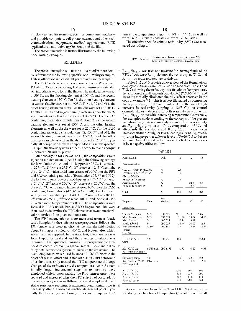
The present invention will now be illustrated in more detail by reference to the following specific, non-limiting examples. Unless otherwise indicated, all percentages are by weight. The PTC materials were compounded on a Werner and
Pfleiderer 25 mm co-rotating 10-barrel twin-screw extruder. All ingredients were fed at the throat. The intake Zone was set at 50° C., the first heating element at 100° C. and the second heating element at 150° C. For #4, the other heating elements as well as the die were set at 190° C. For #1, #9 and #11, the other heating elements as well as the die were set at 210°C. For the PBT (#5 and #6)-containing materials, the other heat ing elements as well as the die were set at 250° C. For the PA6 containing materials (formulations #10 and #12), the second heating element was set at 150° C. and the other heating elements as well as the die were set at 250° C. For the PA66 containing materials (formulations #2, #3, #7 and #8), the second heating element was set at 150° C. and the other heating elements as well as the die were set at 270° C. Typi cally all compositions were compounded at a screw speed of 300 rpm, the throughput was tuned in order to reach a torque of between 70 and 80 percent.
After pre-drying for 4 hrs at 80°C., the compositions were injection molded on an Engel 75 using the following settings for formulation #1, #4 and #11-hopper at 40°C., 1 Zone set at 225°C. 2'' zone at 235° C., 3 Zone set at 245° C. and the die at 240°C. with a mold temperature of 60° C. For the PBT and PA6 containing materials (formulations #5, #6 and #12), the following settings were used-hopper at 40°C., 1 Zone set at 240°C.,2" zone at 250° C., 3" zone set at 260° C. and the die at 255° C. with a mold temperature of 60° C. For the PA66 containing formulations (#2, #3, #7 and #8), the following settings were used-hopper at 40°C., 1 Zone set at 270° C. 2" zone at 275°C.,3' zone set at 280° C. and the die at 275° C. with a mold temperature of 60°C. The compositions were formed into ISO-tensile bars and ISO-impact bars that were then used to determine the PTC characteristics and mechani cal properties of the given composition. The PTC characteristics were measured using a “static
test”. Samples for the static test were prepared as follows: the ISO-tensile bars were notched at the straight mid section about 7 cm apart, cooled to -40°C. and broken, after which silver paint was applied. In the static test, a temperature was forced upon the material and the resulting resistance was measured. The equipment consists of a programmable tem perature controlled oven, a special sample block and a Kei thley data acquisition system to measure the resistance. The oven temperature was raised in steps of -20°C. prior to the onset of the PTC effect and in steps of 5-10°C. just before and after the onset. Only around the PTC temperature did large changes of the resistance vs. the temperature occur. AS Such initially larger incremental steps in temperature were employed which, upon nearing the PTC temperature, were reduced and increased after the PTC effect had occurred. To ensure a homogeneous well-through heated Sample and to get stable resistance readings, a minimum conditioning time is necessary after the oven has reached its new set point. Typi cally the following conditioning times were employed: 25
10
15
25
30
35
40
45
50
55
60
65
18 min in the temperature range from RT to 115° C. as well as from 140°C. upwards and 40 min from 120 to 140°C. The effective specific volume resisitivity (SVR) was mea
Sured according to:
Resistance (Ohm) : Fracture Area (cm^2) Length of sample(electrode distance) (cm) SVR (Ohm.cm) =
R. /R. was used as a measure for the magnitude of the PTC effect, were R. denotes the resistivity at X C. and R. the room temperature resistivity.
Tables 1, 2 and 3 provide an overview of the formulations employed in these examples. As can be seen from Table 1 and FIG. 2 (showing the resistivity as a function of temperature), the addition of small amounts of nylon 6.6 (“PA66 at 7.5 and 15 wt %) virtually eliminated the NTC effect observed in the control example (#1). This is at best illustrated by comparing the R. /Rs PTC amplitudes. After the initial high increase in resistivity (topping at 135° C.) the control example shows a decrease in both resistivty as well as the R. /R- value with increasing temperature. Conversely, the examples made according to the concepts of the present invention using PA66 show only a minor drop in resistivity and R. /R value at 140° C. compared to 135° C. and afterwards the resistivity and R. /R. value even increases further. At higher PA66 loadings (15 wt %), ductil ity drops but properties at lower levels of PA66 (7.5 wt %) are well maintained. Based on the current MVR data there seems to be a negative effect on flow.
TABLE 1
Formulation Unit #1 #2 #3
Item description
Hostalen GD7255 (Basell) % 45 EXXELORMIDEX 101-2 % 5 (ExxonMobil) Printex G (Degussa) % 50 Formulation #1 % 92.5 85 Polyamide 66 low IV % 7.5 15
Tota % 100 1OO 100
Test Property Unit Method #1 #2 #3
Mechanical
Tensile Modulus MPa. ISO 527 2471 2749 280S Max. Tensile stress MPa. ISO 527 31.06 33.04 34:12 Yield Strain % ISO 527 4.24 3.41 Strain at break % ISO 527 10.44 10.O2 2.6 Zod Unnotched kJ/m? ISO 18O 37 35.15 13.24 impact Thermal
HDT 0.45 MPa. o C. ISO 75 108 110.43 MVR
265° C./10 kg ml. 10 min ISO 1133 1.32 O.23 O.38 PTC-characteristics
Switching temp o C. 128 128 128 Resistivity at 23°C. Ohm cm 1.13 1.68 2.14 PTC amplitude
R13so cR230 c. 12O2 660 3O8 R1400 cf R230 c. 528 635 291 R 145 cf R230 c. 350 674 316 R16sec? R230 c. 218 989 S64
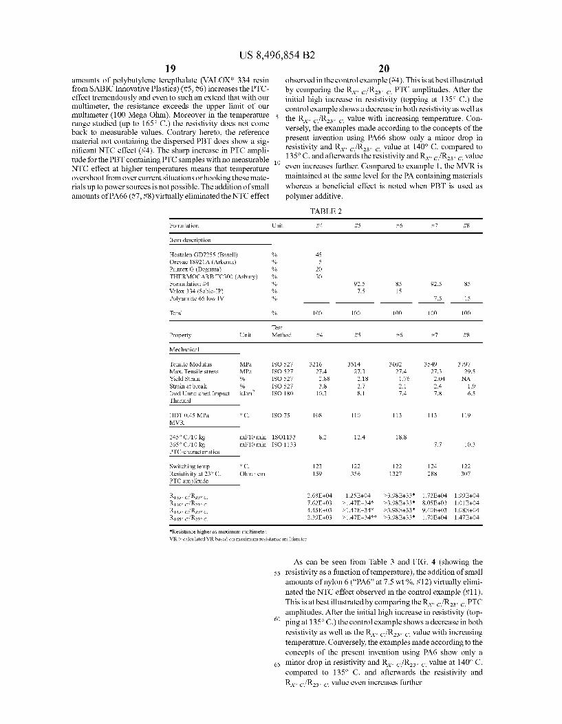
As can be seen from Table 2 and FIG. 3 (showing the resistivity as a function oftemperature), the addition of small
US 8,496,854 B2 19
amounts of polybutylene terepthalate (VALOX* 334 resin from SABIC Innovative Plastics) (#5, #6) increases the PTC effect tremendously and even to such an extend that with our multimeter, the resistance exceeds the upper limit of our multimeter (100 Mega Ohm). Moreover in the temperature range studied (up to 165° C.) the resistivity does not come back to measurable values. Contrary hereto, the reference material not containing the dispersed PBT does show a sig nificant NTC effect (#4). The sharp increase in PTC ampli tude for the PBT containing PTC samples with no measurable NTC effect at higher temperatures means that temperature overshoot from over current situations orhooking these mate rials up to power sources is not possible. The addition of small amounts of PA66 (#7, #8) virtually eliminated the NTC effect
Formulation
Item description
Hostalen GD7255 (Basell) Orevac 18921A (Arkema) Printex G (Degussa) THERMOCARB TC300 (Asbury) Formulation #4 Valox 334 (Sabic-IP) Polyamide 66 low IV
Total
Property Unit
Mechanical
MPa. MPa. %
Tensile Modulus Max. Tensile stress Yield Strain Strain at break Zod Unnotched Impact Thermal
HDT 0.45 MPa. MVR
ml. 10 min ml. 10 min
245° C./10 kg 265° C./10 kg PTC-characteristics
o C. Ohm cm
Switching temp Resistivity at 23° C. PTC amplitude
Resistance higher as maximum multimeter,
20 observed in the control example (#4). This is at best illustrated by comparing the R. /R. PTC amplitudes. After the initial high increase in resistivity (topping at 135° C.) the control example shows a decrease in both resistivity as well as
5 the R. /R. value with increasing temperature. Con versely, the examples made according to the concepts of the present invention using PA66 show only a minor drop in resistivity and R. /R. value at 140° C. compared to 135°C. and afterwards the resistivity and R/Rs value
" even increases further. Compared to example 1, the MVR is maintained at the same level for the PA containing materials whereas a beneficial effect is noted when PBT is used as polymer additive.
TABLE 2
Unit i4 #5 #6 #7 #8
% 45 % 5 % 2O % 30 % 92.5 85 92.5 85 % 7.5 15 % 7.5 15
% 100 1OO 1OO 100 1OO
Test Method i4 #5 #6 #7 #8
ISO 527 3216 3514 3602 3549 3797 ISO 527 27.4 27.3 27.4 27.3 29.5 ISO 527 2.88 2.18 1.76 2.04 NA ISO 527 3.8 2.7 2.1 2.4 1.9 ISO 18O 10.3 8.1 7.4 7.8 6.5
ISO 75 108 110 113 113 119
1SO1133 8.2 12.4 18.8 ISO 1133 7.7 10.3
123 122 122 124 122 159 356 1327 288 307
2.68E+04 12SE+04 >3.98E+33* 1.72E--04 1.99E-04 7.62E--O3 >1.47E-34* >3.98E-33* 8. OSE-O3 1.01E--04 4.45E-03 >1.47E-34* >3.98E-33* 9.4OE--O3 1.08E--O4 2.39E-03 >1.47E-34** >3.98E-33* 1.7OE-04 147E--04
WRs calculated WR based on maximum resistance multimeter,
55
60
65
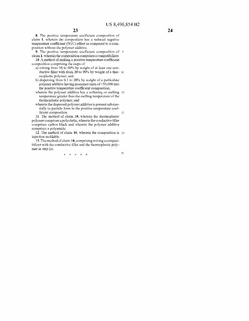
As can be seen from Table 3 and FIG. 4 (showing the resistivity as a function oftemperature), the addition of small amounts of nylon 6 (“PA6” at 7.5 wt %, #12) virtually elimi nated the NTC effect observed in the control example (#11). This is at best illustrated by comparing the RefR - PTC amplitudes. After the initial high increase in resistivity (top ping at 135°C.) the control example shows a decrease in both resistivity as well as the RefR - , Value with increasing temperature. Conversely, the examples made according to the concepts of the present invention using PA6 show only a minor drop in resistivity and R. /R. value at 140° C. compared to 135° C. and afterwards the resistivity and RefR - , Value even increases further

US 8,496,854 B2
TABLE 3
Formulation Unit #9 #10 #11
Item description
Hostalen GC7260 (Basell) % 47.5 25 Ethylene acrylate copolymer Elvaloy % 2.5 PT 862 (Dupont) Printex G (Degussa) % 50 Fusabond MD100 (Dupont) % 30 Domamid 24 (PA6) (DOMO) % 70 #9 50
#10 Thermocarb TC300 (Asbury) % 25
Total % 100 100 100
Test Property Unit Method #9 #10 #11
Mechanical
Tensile Modulus MPa. ISO 527 3457 Max. Tensile stress MPa. ISO 527 27.97 Strain at break % ISO 527 2.30 Zod Unnotched Impact kJ/m’ ISO 18O 7.78 Thermal
HDT 0.45 MPa. o C. ISO 75 107.70 MVR
265° C./10 kg ml. 10 min ISO 1133 3141 PTC-characteristics
Switching temp o C. 128 Resistivity at 23°C. Ohm cm 9.06 PTC amplitude
R13so cf R23 c. 71750 R 140 cf R23 c. 659 R 145 cf R23 c. 538 R16sec? R23 c. 362
While the embodiments have been set forth for the purpose of illustration, the foregoing descriptions should not be deemed to be a limitation on the scope of the invention. Accordingly, various modifications, adaptations, and alterna tives may occur to one skilled in the art without departing from the spirit and scope of the present invention. What is claimed is: 1. A positive temperature coefficient composition compris
1ng: a) from 20 to 90% by weight of a thermoplastic polymer; b) from 10 to 60% by weight of at least one conductive
filler; and c) from 0.1 to 20% by weight of a particulate polymer
additive having monomer units of <50,000; wherein the polymer additive has a melting or softening
temperature greater than the melting temperature of the thermoplastic polymer;
wherein the particulate polymer additive is dispersed in the positive temperature coefficient composition.
2. The positive temperature coefficient composition of claim 1 wherein the thermoplastic polymer is selected from high-density polyethylene, linear low-density polyethylene, low-density polyethylene, mid-density polyethylene, maleic anhydride functionalized polyethylene, a maleic anhydride functionalized elastomeric ethylene copolymer, an ethylene butene copolymer, an ethylene-octene copolymer, an ethyl ene-acrylate copolymer, glycidyl methacrylate modified polyethylene, polypropylene, maleic anhydride functional ized polypropylene, glycidyl methacrylate modified polypro pylene, polyvinyl chloride, polyvinyl acetate, polyvinyl
22
#12
14.3
50 10.7 25
#12
4104 31.71 18O 7.45
115.73
10.41
128 10.97
147036
40
45
50
55
60
65
44446 46369 S8848
acetyl, acrylic resin, syndiotactic polystyrene, polyphe nylene-Sulfide, polyamideimide, polyimide, polyetherether ketone, polyetherketone, polyethylene vinyl acetate, glycidyl methacrylate modified polyethylene vinyl acetate, polyviny lalcohol, polyisobutylene, poly(vinylidene chloride), poly (vinylidene fluoride), poly(methylacrylate), polyacryloni trile, polybutadiene, polyesters, polyethylene-terephthalate, polybutylene-terephthalate, poly(8-aminocaprylic acid), poly(vinyl alcohol), polycaprolactone, polyamides or blends or a combination including at least one of the forgoing poly CS.
3. The positive temperature coefficient composition of claim 2, wherein the polyamide is selected from PA 11, PA12, PA6, PA6.6, PA 6.10, polyphthalamide, high temperature nylon or blends or a combination including at least one of the forgoing polyamides.
4. The positive temperature coefficient composition of claim 1 wherein the conductive filler is selected from a ceramic filler, a metallic filler, a carbon-containing filler or a combination including at least one of the foregoing fillers.
5. The positive temperature coefficient composition of claim 1 wherein the polymer additive comprises a polyamide polymer.
6. The positive temperature coefficient composition of claim 1, wherein the thermoplastic polymer comprises a poly olefin, wherein the conductive filler comprises carbon black and wherein the polymer additive comprises a polyamide.
7. An article of manufacture comprising the composition of claim 1.
US 8,496,854 B2 23
8. The positive temperature coefficient composition of claim 1, wherein the composition has a reduced negative temperature coefficient (NTC) effect as compared to a com position without the polymer additive.
9. The positive temperature coefficient composition of 5 claim 1, wherein the composition comprises a compatibilizer.
10. A method of making a positive temperature coefficient composition comprising the steps of:
a) mixing from 10 to 60% by weight of at least one con ductive filler with from 20 to 90% by weight of a ther- 10 moplastic polymer; and
b) dispersing from 0.1 to 20% by weight of a particulate polymer additive having monomer units of <50,000 into the positive temperature coefficient composition;
wherein the polymer additive has a softening or melting 15 temperature greater than the melting temperature of the thermoplastic polymer; and
wherein the dispersed polymer additive is present substan tially in particle form in the positive temperature coef ficient composition. 2O
11. The method of claim 10, wherein the thermoplastic polymer comprises a polyolefin, wherein the conductive filler comprises carbon black and wherein the polymer additive comprises a polyamide.
12. The method of claim 10, wherein the composition is 25 injection moldable.
13. The method of claim 10, comprising mixing a compati bilizer with the conductive filler and the thermoplastic poly mer in step (a).
30
24