12 systems analysis and design in a changing world, fifth edition
TRANSCRIPT
12Systems Analysis and Design in a
Changing World, Fifth Edition
12
2
Learning Objectives
Explain the different types of objects and layers in a design
Develop sequence diagrams for use case realization
Develop communication diagrams for detailed design
Develop updated design class diagrams
Develop multilayer subsystem packages
Explain design patterns and recognize various specific patterns

12
3
Overview
Primary focus of this chapter is how to develop detailed sequence diagrams to design use cases
The first-cut sequence diagram focuses only on the problem domain classes
The complete multi-layer design includes the data access layer and the view layer
Design Patterns are an important concept that is becoming more important for system development
12
4
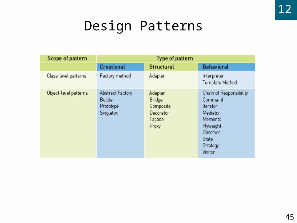
Design Patterns and the Use Case Controller
Design pattern A standard solution template to a design requirement
that facilitates the use of good design principles
Use case controller pattern Design requirement is to identify which problem
domain class should receive input messages from the user interface for a use case

12
5
Design Patterns and the Use Case Controller (continued)
Solution is to choose a class to serve as a collection point for all incoming messages for the use case. Controller acts as intermediary between outside world and internal system
Artifact – a class invented by a system designer to handle a needed system function, such as a controller class

12
6
Use Case Controller
Pattern

12
7
Use Case Realization with Sequence Diagrams
Realization of use case done through interaction diagram development
Determine what objects collaborate by sending messages to each other to carry out use case
Sequence diagrams and communication diagrams represent results of design decisions
Use well-established design principles such as coupling, cohesion, separation of responsibilities
12
8
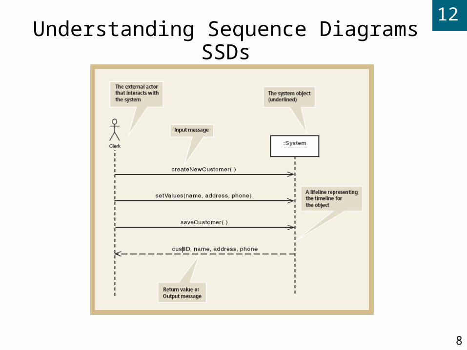
Understanding Sequence DiagramsSSDs

12
9
Detailed Sequence Diagram
Figure 12-3

12
10
Designing with Sequence Diagrams
Sequence diagrams used to explain object interactions and document design decisions
Document inputs to and outputs from system for single use case or scenario
Capture interactions between system and external world as represented by actors
Inputs are messages from actor to system
Outputs are return messages showing data

12
11
Object Responsibility Objects are responsible for system processing
Responsibilities include knowing and doing Knowing about object’s own data and other classes of
objects with which it collaborates to carry out use cases
Doing activities to assist in execution of use case Receive and process messages
Instantiate, or create, new objects required to complete use case
Design means assigning responsibility to the appropriate classes based on design principles and using design patterns

12
12
First-Cut Sequence Diagram
Start with elements from SSD
Replace :System object with use case controller
Add other objects to be included in use case
Select input message from the use case
Add all objects that must collaborate
Determine other messages to be sent
Which object is source and destination of each message?

12
13
SSD for Cancel an Order

12
14
First Cut Design Class
Diagram for Cancel an
Order
12
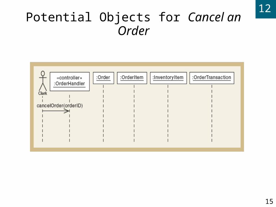
15
Potential Objects for Cancel an Order

12
16
First Cut Sequence Diagram for Cancel an Order
12
17
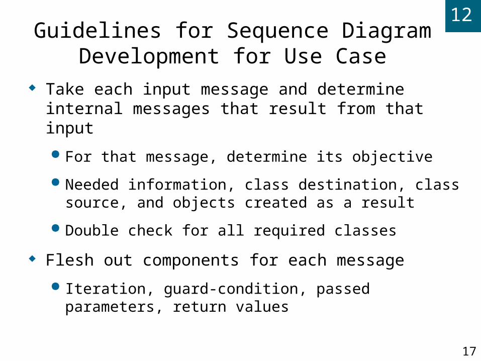
Guidelines for Sequence Diagram Development for Use Case
Take each input message and determine internal messages that result from that input
For that message, determine its objective
Needed information, class destination, class source, and objects created as a result
Double check for all required classes
Flesh out components for each message
Iteration, guard-condition, passed parameters, return values

12
18
Assumptions About First-Cut Sequence Diagram
Perfect technology assumption
Don’t include system controls like login/logout (yet)
Perfect memory assumption
Don’t worry about object persistence (yet)
Assume objects are in memory ready to work
Perfect solution assumption
Don’t worry about exception conditions (yet)
Assume happy path/no problems solution

12
19
SSD for Create new phone order
12
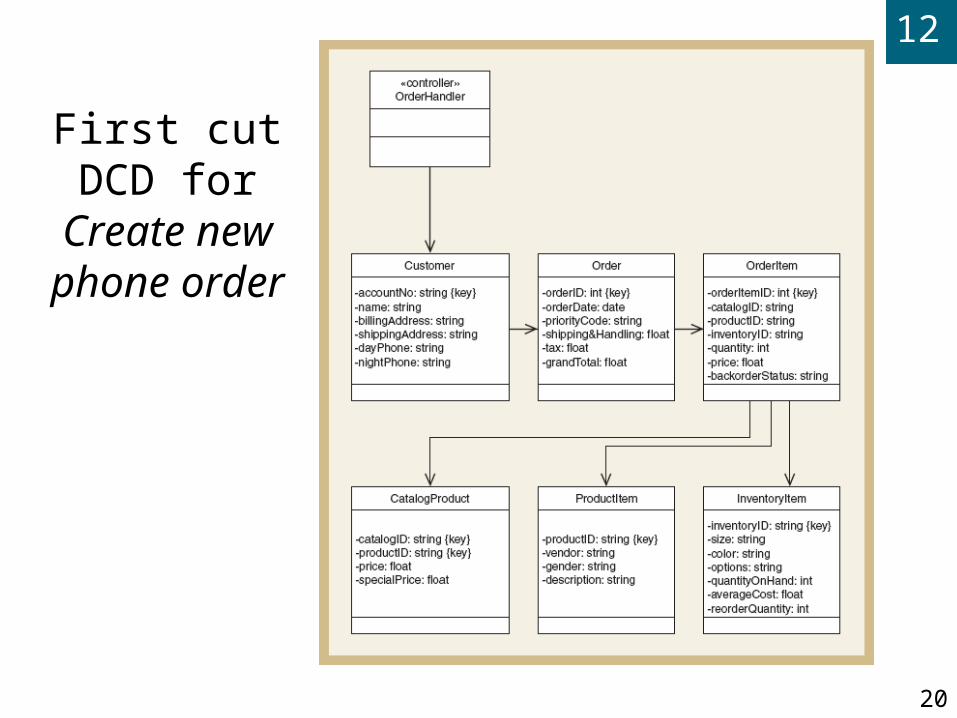
20
First cut DCD for Create new phone
order

12
21
Sequence Diagram for First Input Message
12
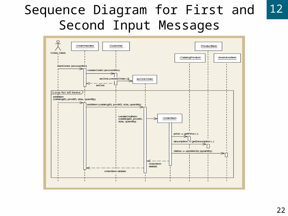
22
Sequence Diagram for First and Second Input Messages
12
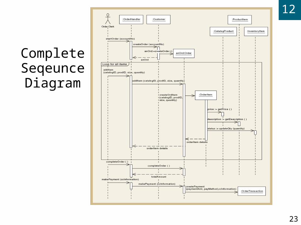
23
Complete Seqeunce Diagram

12
24
Developing a Multilayer Design
First-cut sequence diagram – use case controller plus classes in domain layer
Add data access layer – design for data access classes for separate database interaction
No more perfect memory assumption
Separation of responsibilities
Add view layer – design for user-interface classes
Forms added as windows classes to sequence diagram between actor and controller
12
25
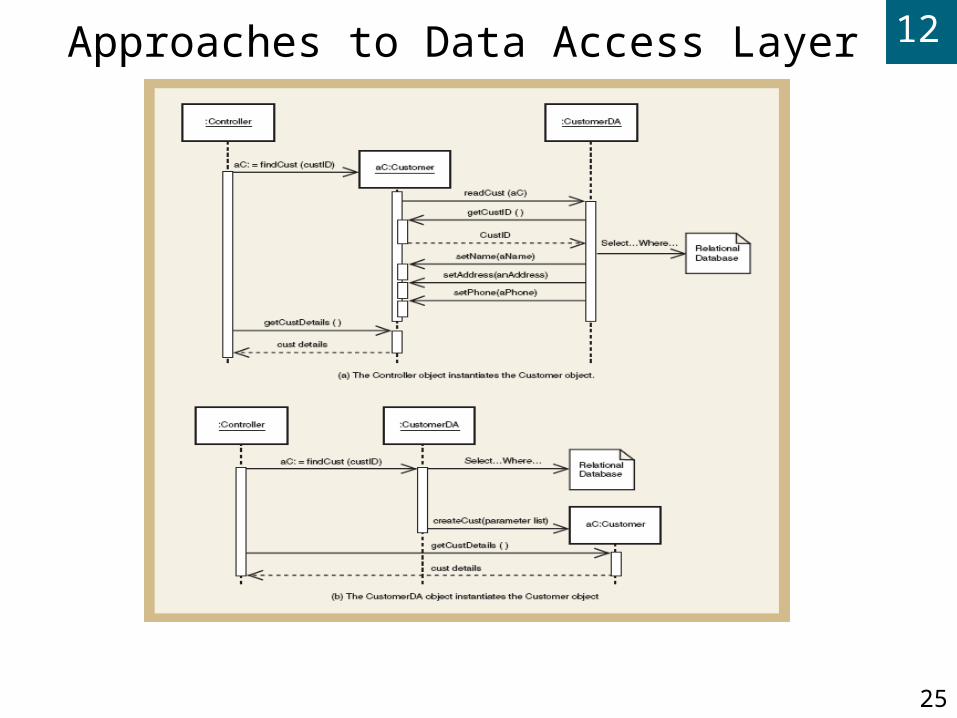
Approaches to Data Access Layer

12
26
Approaches to Data Access Layer (continued)
Create data access class for each domain class
CustomerDA added for Customer
Database connection statements and SQL statements separated into data access class. Domain classes do not have to know about the database design or implementation
Approach (a) – controller instantiates new customer aC; new instance asks DA class to populate its attributes reading from the database
12
27
Approaches to Data Access Layer (continued)
Approach (b) – controller asks DA class to instantiate new customer aC; DA class reads database and passes values to customer constructor
Two following examples use this approach

12
28
Adding Data Access Layer for Cancel an order
12
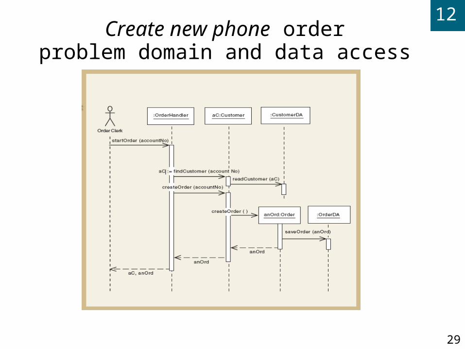
29
Create new phone orderproblem domain and data access
12
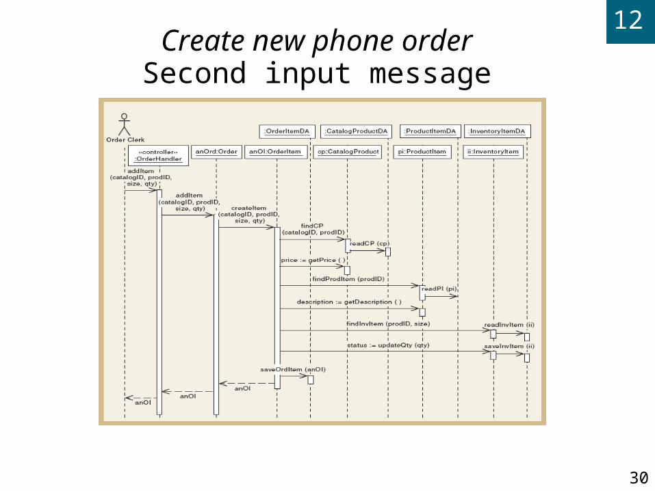
30
Create new phone orderSecond input message
12
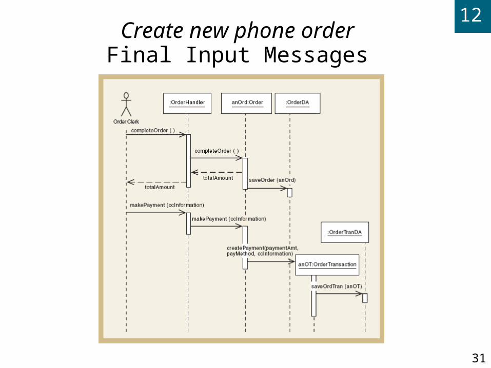
31
Create new phone orderFinal Input Messages

12
32
Designing the View Layer
Add GUI forms or Web pages between actor and controller for each use case
Minimize business logic attached to a form
Some use cases require only one form; some require multiple forms and dialog boxes
View layer design is focused on high-level sequence of forms/pages – the dialog
Details of interface design and HCI in Chapters 13 and 14
12
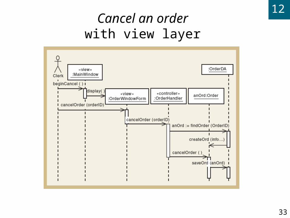
33
Cancel an orderwith view layer

12
34
Create new phone orderwith view layer
12
35
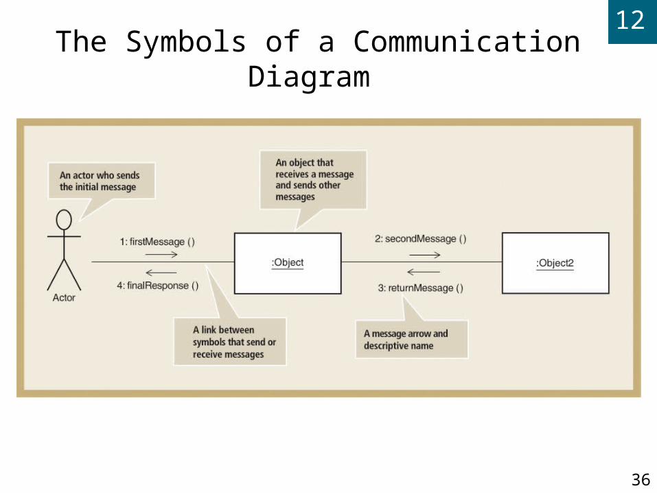
Designing with Communication Diagrams
Communication diagrams and sequence diagrams
Both are interaction diagrams
Both capture same information
Process of designing is same for both
Model used is designer’s personal preference
Sequence diagram – use case descriptions and dialogs follow sequence of steps
Communication diagram – emphasizes coupling
12
36
The Symbols of a Communication Diagram

12
37
A Communication Diagram for Create new phone order

12
38
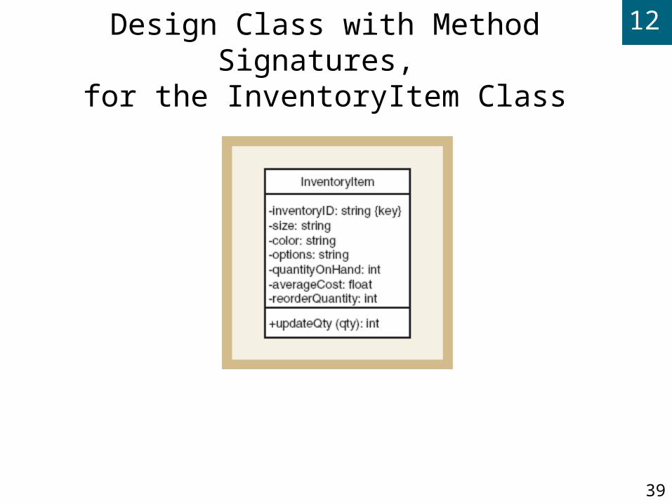
Updating the Design Class Diagram
Design class diagrams developed for each layer
New classes for view layer and data access layer
New classes for domain layer use case controllers
Sequence diagram’s messages used to add methods
Constructor methods
Data get and set method
Use case specific methods
12
39
Design Class with Method Signatures, for the InventoryItem Class

12
40
Updated Design Class
Diagram for the
Domain Layer

12
41
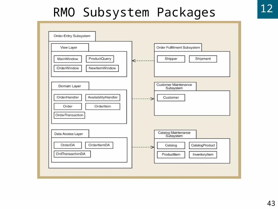
Package Diagram—Structuring the Major Components
High-level diagram in UML to associate classes of related groups
Identifies major components of a system and dependencies
Determines final program partitions for each layer
View, domain, data access
Can divide system into subsystem and show nesting within packages

12
42
Partial Design of Three-Layer
Package Diagram for
RMO
12
43
RMO Subsystem Packages

12
44
Implementation Issues for Three-Layer Design
Construct system with programming
Java or VB .NET or C# .NET
IDE tools (Visual Studio, Rational Application Developer, JBuilder)
Integration with user-interface design, database design, and network design
Use object responsibility to define program responsibilities for each layer
View layer, domain layer, data access layer
12
45
Design Patterns

12
46
Adapter Pattern

12
47
Factory or Factory Method Pattern

12
48
Singleton Pattern

12
49
Create new order -- Observers
12
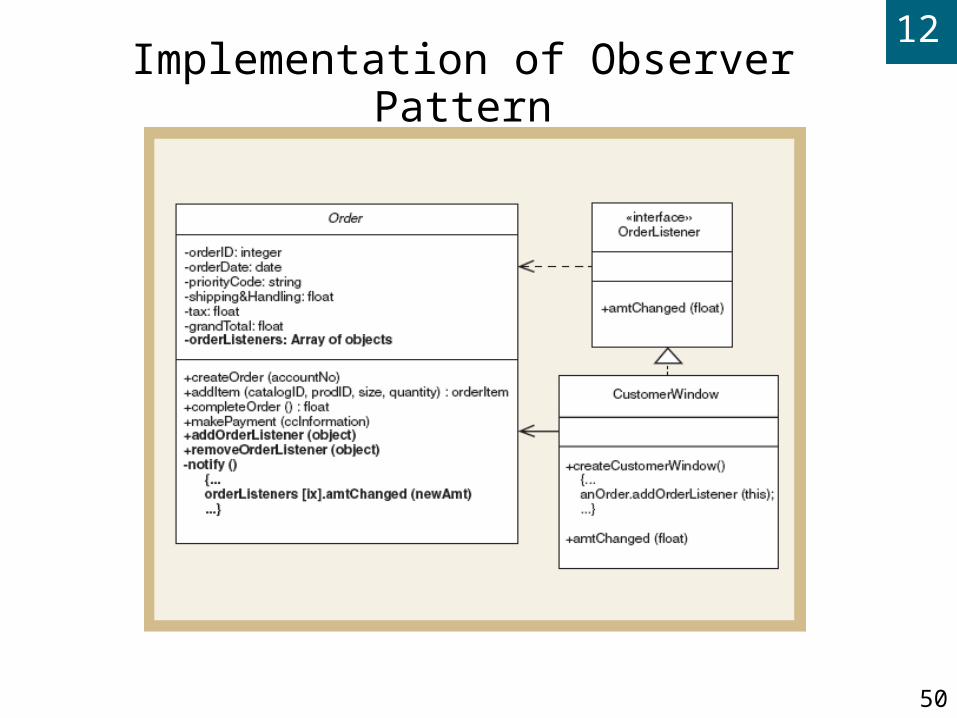
50
Implementation of Observer Pattern
12
51
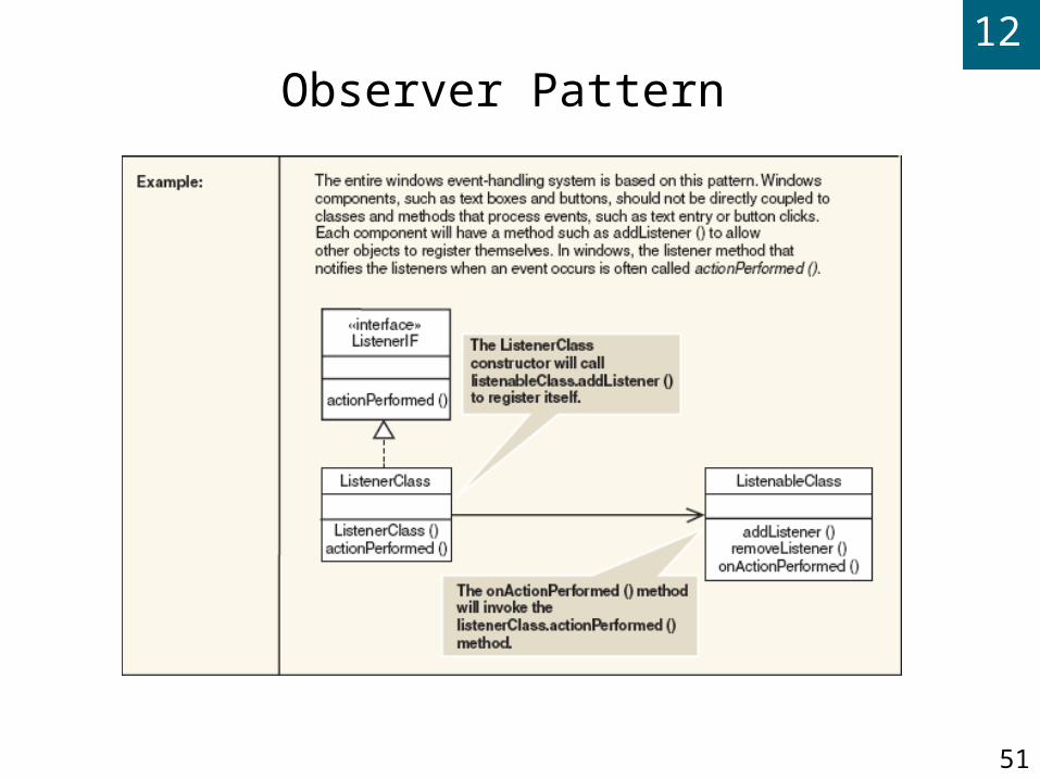
Observer Pattern

12
52
Summary
Systems design is driven by use cases, design class diagrams, and sequence diagrams Domain class diagrams are transformed into design
class diagrams
Sequence diagrams are extensions of system sequence diagrams (SSDs)
System Sequence Diagrams Capture method signatures
Show navigation visibility

12
53
Summary (continued) Package Diagrams show subsystem organization
and dependencies
Design Patterns are useful solutions to standard programming problems
Use Case Controller (MVC pattern)
Adpater
Factory and Singleton
Observer