12. resource planning - nasa resource planning process is the mechanism by ... the site m&o...
TRANSCRIPT

12. Resource Planning
The Resource Planning process is the mechanism by which reservations for non-routine ground events are defined and controlled. Such events may include testing, preventive maintenance or upgrades, or any other event that requires DAAC resources. Resource planning defines ground events, which are also used in production planning; thus, resource planning can take place whenever a production plan needs to be created. In general, this will occur on a biweekly basis for 30-day plans, on a weekly basis for ten-day plans, and on a daily basis. However, ground events can be entered at any time.
The site M&O Resource Planner uses the Resource Scheduler within the Planning Subsystem to schedule non-routine events against ECS resources.
In addition to the Resource Scheduler, Resource Planning provides a Resource Editor to add resources or to modify the characteristics of the resources. Step-by-step procedures for using the Resource Editor are presented in Section 12.2. Step-by-step procedures for using the Resource Scheduler are presented in Section 12.3.
12.1 Resource Planning Process
Resources, which are defined and subsequently used in production planning, are strings (computers and storage devices); computers; and disks. Other generic hardware devices may also be defined and managed. The Resource Planning list is initialized with the resource data from the Baseline Manager database. Resources may be added to or deleted from the Resource Planning list without affecting the Baseline Manager database. This is useful, for example, for identifying resources that will be available in the future.
The Resource Planner views requests for resource reservations to determine if the requests are valid. Requests for resource reservations come from the local DAAC Resource Manager. Requests include information, such as activity description, resource requirements, and time requested to use the resource (acceptable variances may be specified in comments field). The Resource Planner may decide to forward the request to a "subject-matter-expert," whose expertise is particularly relevant to the request, in order to validate a request. (The subjectmatter-expert is referred to as the "sponsor" by the system; see Section 12.3.2, Step 3.)
Should the subject-matter-expert agree that the request to reserve the resource is valid, the Resource Planner will approve it along with all other requests that have been validated, and generate a Resource Plan, which is in effect a set of committed resource reservations. The Plan will be submitted to a review board (members to be determined) for the board's consideration. The review board will confirm that the reserved resources will not adversely impact scheduled events. Once approved by the review board, the Resource Planner will "commit" the Plan. The system will then automatically forward the Plan to Production Planning for scheduling.
12-1 611-CD-500-001

Each procedure outlined will have an Activity Checklist table that will provide an overview of the task to be completed. The outline of the Activity Checklist is as follows:
Column one - Order shows the order in which tasks could be accomplished.
Column two - Role lists the Role/Manager/Operator responsible for performing the task.
Column three -Task provides a brief explanation of the task.
Column four - Section provides the Procedure (P) section number or Instruction (I) section number where details for performing the task can be found.
Column five - Complete? is used as a checklist to keep track of which task steps have been completed.
Table 12.1-1, below, provides an Activity Checklist table, of Resource Planning activities.
Table 12.1-1. Resource Planning - Activity Checklist Order Role Task Section Complete?
1 Resource Planner Launch the Resource Editor (P) 12.2.1
2 Resource Planner Synchronize Resource Listings (P) 12.2.2
3 Resource Planner Determine Actual Processing Resources
(P) 12.2.3
4 Resource Planner Add a Resource (P) 12.2.4
5 Resource Planner Modify a Resource (P) 12.2.5
6 Resource Planner Delete a Resource (P) 12.2.6
7 Resource Planner or DAAC Staff
Launch the Resource Scheduler (P) 12.3.1
8 Resource Planner or DAAC Staff
Create a Resource Reservation Request
(P) 12.3.2
9 Resource Planner or DAAC Staff
Edit a Resource Reservation Request (P) 12.3.3
10 Resource Planner or Sponsor
Validate or Reject a Resource Reservation Request
(P) 12.3.4
11 Resource Planner Approve a Resource Reservation Request
(P) 12.3.5
12 Resource Manager/Resource Planner
Commit Resource Reservation Requests
(P) 12.3.6
13 Resource Planner Review the Resource Timeline (P) 12.3.7
14 Resource Planner Delete a Resource Reservation Request
(P) 12.3.8
15 Resource Planner or DAAC Staff
Shut Down Resource Planning Applications
(P) 12.4
12-2 611-CD-500-001

12.2 Resource Editor
The Resource Editor allows the authorized user to add resources or to modify the characteristics of the resources. The user can synchronize the resource planning list with the baseline set of system resources and can add or delete future resources not contained in the baseline resource list. Modifications to the resource planning list are recorded in the PDPS database. These modifications are not recorded in the Baseline Manager database.
The hardware resources for which resource planning can be supported include host computers, storage devices, as well as ‘strings’ that are made up of sets of computers.
12.2.1 Launch the Resource Editor
The Resource Editor is invoked from a UNIX command line prompt. Table 12.2-1 presents (in a condensed format) the steps required to launch the Resource Editor GUI. If you are already familiar with the procedures, you may prefer to use the quick-step table. If you are new to the system, or have not performed this task recently, you should use the following detailed procedures:
1 At the UNIX command line prompt type xhost hostname then press the Return/Enter key on the keyboard. a. hostname refers to the host on which GUIs are to be launched during the current
operating session. Multiple hostnames can be specified on the same line. b. The use of xhost + is discouraged because of a potential security problem.
2 Type setenv DISPLAY clientname:0.0 then press the Return/Enter key. a. Use either the X terminal/workstation IP address or the machine-name for the
clientname. b. When using secure shell, the DISPLAY variable is set just once, before logging in to
remote hosts. If it were to be reset after logging in to a remote host, the security features would be compromised.
3 Open another UNIX (terminal) window.
4 Start the log-in to the Planning/Management Workstation by typing /tools/bin/ssh hostname (e.g., e0pls03, g0pls01, l0pls02, or n0pls02) in the new window then press the Return/Enter key. a. If you have previously set up a secure shell passphrase and executed sshremote, a
prompt to Enter passphrase for RSA key '<user@localhost>' appears; continue with Step 5.
b. If you have not previously set up a secure shell passphrase; go to Step 6.
5 If a prompt to Enter passphrase for RSA key '<user@localhost>' appears, type your Passphrase then press the Return/Enter key. a. Go to Step 7.
6 At the <user@remotehost>’s password: prompt type your Password then press the Return/Enter key.
7 In the Terminal window, at the command line, enter:
12-3 611-CD-500-001

cd /usr/ecs/<MODE>/CUSTOM/utilities a. <MODE> identifies the current operating mode
1. TS1 - Science Software Integration and Test (SSI&T) 2. TS2 - New Version Checkout 3. OPS - Normal Operations
b. “utilities” is the directory containing the Planning Subsystem start-up scripts.
8 Set the necessary environment variables by entering:
setenv ECS_HOME /usr/ecs/ a. Application home environment is entered. b. When logging in as a system user (e.g., cmshared), the ECS_HOME variable may be
set automatically so it may not be necessary to set it manually.
9 Enter EcPlRpAllStart <MODE> <application_id> a. The Resource Planning background processes are launched. b. The application_id or MSGSRV_ID is a number from 1 to 5. It identifies the
message service in use so messages can be directed to the proper message handler GUI. Consequently, it is a good idea to use the same application_id consistently during a resource planning session.
10 Enter EcPlRpReStart <MODE> <application_id> a. The Resource Editor GUI is launched. b. The Resource Editor GUI displays a list of defined resources and a series of buttons
that enable the following operations: 1. New... Add a resource definition. (Section 12.2.3) 2. Modify... Edit or review the details of an existing resource definition.
(Section 12.2.4) 3. Delete Delete a resource definition. (Section 12.2.5) 4. Fetch Baseline Generates a report from the Baseline Manager to the
Resource Planning workstation. The report is an ASCII listing of the production baseline. Used in synchronizing the baseline. (Section 12.2.2)
5. Load Baseline Synchronizes the PDPS database with the baselined resource information. (Section 12.2.2)
12-4 611-CD-500-001

Table 12.2-1. Launch the Resource Editor - Quick-Step Procedures Step What to Enter or Select Action to Take
1 Log in to the ECS System using secure shell enter text, press Enter
2 Enter cd /usr/ecs/<MODE>/CUSTOM/utilities enter text, press Enter
3 Set the environment variables enter text, press Enter
4 Enter EcPlRpAllStart <MODE> <application_id>
enter text, press Enter
5 Enter EcPlRpReStart <MODE> <application_id>
enter text, press Enter
12.2.2 Synchronize Resource Listings
NOTE: Before attempting to synchronize resource listings, ask the local Configuration Management Administrator whether the resources have been defined in the Baseline Manager database at your site. If the resources have not been defined in the Baseline Manager, they will have to be added to the Resource Planning list as described in the Add a Resource procedure.
This function synchronizes the Resource tables with the Baseline Manager. Table 12.2-2 presents (in a condensed format) the steps required to synchronize resource listings. If you are already familiar with the procedures, you may prefer to use the quick-step table. If you are new to the system, or have not performed this task recently, you should use the following detailed procedure:
1 Launch the Resource Editor GUI by executing Steps 1-10 of Section 12.2.1 (if the Resource Editor GUI is not currently running) then continue with the following steps.
2 From the Resource Editor GUI, click on the Fetch Baseline button. a. The Baseline Request pop-up dialog box is displayed requesting entry of the desired
baseline date.
3 Type the date for the desired baseline (in DD MMM YYYY format) in the Enter Baseline Date field. a. For example: 01 JAN 1999
4 Click on the OK button to apply the baseline date and dismiss the Baseline Request popup window. a. This action will generate a report from the Baseline Manager to the Resource
Planning workstation. The report is an ASCII listing of the production baseline.
5 From the Resource Editor GUI, click on the Load Baseline button. This action will synchronize the PDPS database with the baselined resource information.
6 To exit, select Exit from the File menu.
12-5 611-CD-500-001

1
2
3
4
5
6
Table 12.2-2. Synchronize Resource Listings - Quick-Step Procedures Step What to Enter or Select Action to Take
Launch the Resource Editor GUI Use procedure in Section 12.2.1
Select the Fetch Baseline button single-click
Enter the date for the desired baseline enter text
Select OK single-click
Select the Load Baseline button single-click
Select File → Exit to quit the GUI single-click
12.2.3 Determine Actual Processing Resources
The Resource Editor allows the authorized operator to define resources in the following categories:
a. Disks: Disk partitions that are associated with and provide temporary data storage for the input and output files used in processing.
b. Virtual Computers: Virtual computers composed of CPUs, random-access memory (RAM), and associated-disk(s). The CPUs and RAM specified for a virtual computer are components of the real computer from which the virtual computer is derived.
c. Strings: Sets of one or more virtual computers. Strings are associated with the processing software (AutoSys). A dual science processor configuration can be defined by specifying strings containing virtual computers derived from different real computers.
d. Real Computers: Physical computing devices, each of which contains one or more CPUs. Each science processor host (“real” computer) is divided into one or more virtual computers by allocating CPUs and RAM from the real computer to the virtual computer(s).
e. AutoSys: Identifies the string(s) of virtual computers used by the production processing software.
f. Hardware: Any type of equipment that is not defined as a computer or disk may be defined as “hardware.”
The ECS Operational Readiness Plan for Release 2.0 (603-CD-003-001) specifies that initially disk partitions at the DAACs are to be split among the operating modes as follows:
a. OPS – 60%. b. TS1 - 20%. c. TS2 - 20%.
However, it may be advantageous to reserve some nominal percentage of the disk (e.g., two to five percent) as a safety buffer. In any case, it is critical to ensure that the sum of the disk space assigned to the various modes is no more than the total disk space available.
Although the ECS Operational Readiness Plan does not specifically mention allocating resources other than disk partitions, CPUs and RAM need to be allocated among modes in the same manner. However, it is not necessary to be exact with the CPU count or RAM amount.
a. There is no one-to-one mapping of CPU allocation with actual CPUs on the science processor.
b. Actual CPU usage during processing is limited by the operating system (OS). 1. If ten CPUs have been specified for a particular mode, only ten Data Processing
Requests (DPRs) can be running the Execute job at a given time.
12-6 611-CD-500-001

2. What is really being defined is the maximum number of DPRs that will execute at a given time.
c. It is important to monitor the load on each science processor. 1. CPUs can be over-allocated or under-allocated as necessary to get the most out of
the CPUs on each science processor. 2. If monitoring indicates that the processor is underused when OPS mode is at full
processing capacity, the number of CPUs allocated to OPS mode could probably be increased.
3. If the science processor is at full capacity when OPS mode is at full processing capacity and it is suspected that the processor may be overworked, the number of CPUs allocated to OPS mode should be reduced.
d. Random-access memory (RAM) is subject to the same considerations as CPUs. 1. RAM can be over-allocated or under-allocated as necessary to get the most out of
the memory on each science processor. e. The OS takes care of true CPU and RAM allocation.
Another consideration is the throttling of the processing load through the DpPrAutoSysMaxJobs variable. DpPrAutoSysMaxJobs is defined in the EcDpPrJobMgmt.CFG file in the /usr/ecs/MODE/CUSTOM/cfg directory on the Queuing Server (e.g., g0sps06).
a. If DpPrAutoSysMaxJobs in OPS mode is set at 64 [allowing AutoSys to accommodate eight DPRs (consisting of eight jobs each) simultaneously in OPS mode] and ten CPUs are defined for OPS, it would not be possible to utilize all ten CPUs.
b. If the value of DpPrAutosysMaxJobs were increased to 120 (15 DPRs times 8 jobs/DPR), there might be times when the processing of some DPRs was held up because only ten could be running the Execute job at a time.
c. In such a case it might be possible to increase the number of CPUs allocated to the mode so that more than ten DPRs could be running the Execute job simultaneously.
Before data processing resources can be defined, it is necessary to know what resources are actually available at the DAAC. Some resources are defined in terms of other resources; for example, a string is defined as one or more virtual computers. However, it is generally necessary to have the following types of information available in order to define processing resources:
a. Host names [“real computers”]. b. Number of processors [CPUs] available on each host. c. Operating System (OS) for each host. d. Memory [RAM] on each host. e. Total disk space. f. AutoSys instance(s) at the DAAC.
Table 12.2-3 presents (in a condensed format) the steps required to determine the actual processing resources to be defined. If you are already familiar with the procedures, you may prefer to use the quick-step table. If you are new to the system, or have not performed this task recently, you should use the following detailed procedures:
NOTE: The procedure to determine the actual processing resources to be defined starts with the assumption that the xhost hostname command has been given and the DISPLAY environment variable has been set (Refer to Section 12.2.1).
1 At the UNIX command line prompt start the log-in to the applicable Science Processor by typing /tools/bin/ssh hostname (e.g., e0spg01, g0spg01, l0spg01, or n0spg03) in the window then press the Return/Enter key.
12-7 611-CD-500-001

FFFiiillleeesssyyysssttteeemmm TTTyyypppeee kkkbbbyyyttteeesss uuussseee aaavvvaaaiiilll %%%uuussseeeMMMooouuunnnttteeeddd ooonnn///dddeeevvv///dddssskkk///xxxlllvvv///vvvgggooo111 xxxfffsss 444111333333999444666888888 111666444666444666000444888 222444888777444888666444000 444000///vvvooolll111
PPPrrroooccceeessssssooorrr 000::: 111999444 MMMHHHZZZ IIIPPP222555CCCPPPUUU::: MMMIIIPPPSSS RRR111000000000000 PPPrrroooccceeessssssooorrr CCChhhiiippp RRReeevvviiisssiiiooonnn::: 222...666FFFPPPUUU::: MMMIIIPPPSSS RRR111000000111000 FFFllloooaaatttiiinnnggg PPPoooiiinnnttt CCChhhiiippp RRReeevvviiisssiiiooonnn::: 000...000PPPrrroooccceeessssssooorrr 111::: 111999444 MMMHHHZZZ IIIPPP222555CCCPPPUUU::: MMMIIIPPPSSS RRR111000000000000 PPPrrroooccceeessssssooorrr CCChhhiiippp RRReeevvviiisssiiiooonnn::: 222...666FFFPPPUUU::: MMMIIIPPPSSS RRR111000000111000 FFFllloooaaatttiiinnnggg PPPoooiiinnnttt CCChhhiiippp RRReeevvviiisssiiiooonnn::: 000...000PPPrrroooccceeessssssooorrr 222::: 111999444 MMMHHHZZZ IIIPPP222555CCCPPPUUU::: MMMIIIPPPSSS RRR111000000000000 PPPrrroooccceeessssssooorrr CCChhhiiippp RRReeevvviiisssiiiooonnn::: 222...666FFFPPPUUU::: MMMIIIPPPSSS RRR111000000111000 FFFllloooaaatttiiinnnggg PPPoooiiinnnttt CCChhhiiippp RRReeevvviiisssiiiooonnn::: 000...000PPPrrroooccceeessssssooorrr 333::: 111999444 MMMHHHZZZ IIIPPP222555CCCPPPUUU::: MMMIIIPPPSSS RRR111000000000000 PPPrrroooccceeessssssooorrr CCChhhiiippp RRReeevvviiisssiiiooonnn::: 222...666FFFPPPUUU::: MMMIIIPPPSSS RRR111000000111000 FFFllloooaaatttiiinnnggg PPPoooiiinnnttt CCChhhiiippp RRReeevvviiisssiiiooonnn::: 000...000PPPrrroooccceeessssssooorrr 444::: 111999444 MMMHHHZZZ IIIPPP222555CCCPPPUUU::: MMMIIIPPPSSS RRR111000000000000 PPPrrroooccceeessssssooorrr CCChhhiiippp RRReeevvviiisssiiiooonnn::: 222...555FFFPPPUUU::: MMMIIIPPPSSS RRR111000000111000 FFFllloooaaatttiiinnnggg PPPoooiiinnnttt CCChhhiiippp RRReeevvviiisssiiiooonnn::: 000...000PPPrrroooccceeessssssooorrr 555::: 111999444 MMMHHHZZZ IIIPPP222555CCCPPPUUU::: MMMIIIPPPSSS RRR111000000000000 PPPrrroooccceeessssssooorrr CCChhhiiippp RRReeevvviiisssiiiooonnn::: 222...555FFFPPPUUU::: MMMIIIPPPSSS RRR111000000111000 FFFllloooaaatttiiinnnggg PPPoooiiinnnttt CCChhhiiippp RRReeevvviiisssiiiooonnn::: 000...000PPPrrroooccceeessssssooorrr 666::: 111999444 MMMHHHZZZ IIIPPP222555CCCPPPUUU::: MMMIIIPPPSSS RRR111000000000000 PPPrrroooccceeessssssooorrr CCChhhiiippp RRReeevvviiisssiiiooonnn::: 222...555FFFPPPUUU::: MMMIIIPPPSSS RRR111000000111000 FFFllloooaaatttiiinnnggg PPPoooiiinnnttt CCChhhiiippp RRReeevvviiisssiiiooonnn::: 000...000PPPrrroooccceeessssssooorrr 777::: 111999444 MMMHHHZZZ IIIPPP222555CCCPPPUUU::: MMMIIIPPPSSS RRR111000000000000 PPPrrroooccceeessssssooorrr CCChhhiiippp RRReeevvviiisssiiiooonnn::: 222...555FFFPPPUUU::: MMMIIIPPPSSS RRR111000000111000 FFFllloooaaatttiiinnnggg PPPoooiiinnnttt CCChhhiiippp RRReeevvviiisssiiiooonnn::: 000...000PPPrrroooccceeessssssooorrr 888::: 111999444 MMMHHHZZZ IIIPPP222555CCCPPPUUU::: MMMIIIPPPSSS RRR111000000000000 PPPrrroooccceeessssssooorrr CCChhhiiippp RRReeevvviiisssiiiooonnn::: 222...555
a. If you have previously set up a secure shell passphrase and executed sshremote, a prompt to Enter passphrase for RSA key '<user@localhost>' appears; continue with Step 2.
b. If you have not previously set up a secure shell passphrase; go to Step 3.
2 If a prompt to Enter passphrase for RSA key '<user@localhost>' appears, type your Passphrase then press the Return/Enter key. a. Go to Step 4.
3 At the <user@remotehost>’s password: prompt type your Password then press the Return/Enter key.
4 Type cd /usr/ecs/<MODE>/CUSTOM/pdps/<processor>/data/DpPrRm/<processor>_disk then press Return/Enter. a. Change directory to the disk mount point (e.g.,
/usr/ecs/OPS/CUSTOM/pdps/g0spg01/data/DpPrRm/g0spg01_disk).
5 Type df -k . (being sure to include the dot) then press Return/Enter. a. Information concerning disk size and use is displayed; for example:Filesystem Type kbytes use avail %use�Mounted on /dev/dsk/xlv/vgo1 xfs 413394688 164646048 248748640 40 /vol1 a. In the preceding example the total disk space is 413,394,688 kilobytes or
413,394.69 megabytes (413 gigabytes).
6 Type hinv then press Return/Enter. a. Information concerning CPUs and RAM (memory) is displayed; for example (not all
rows are shown): Processor 0: 194 MHZ IP25 CPU: MIPS R10000 Processor Chip Revision: 2.6 FPU: MIPS R10010 Floating Point Chip Revision: 0.0 Processor 1: 194 MHZ IP25 CPU: MIPS R10000 Processor Chip Revision: 2.6 FPU: MIPS R10010 Floating Point Chip Revision: 0.0 Processor 2: 194 MHZ IP25 CPU: MIPS R10000 Processor Chip Revision: 2.6 FPU: MIPS R10010 Floating Point Chip Revision: 0.0 Processor 3: 194 MHZ IP25 CPU: MIPS R10000 Processor Chip Revision: 2.6 FPU: MIPS R10010 Floating Point Chip Revision: 0.0 Processor 4: 194 MHZ IP25 CPU: MIPS R10000 Processor Chip Revision: 2.5 FPU: MIPS R10010 Floating Point Chip Revision: 0.0 Processor 5: 194 MHZ IP25 CPU: MIPS R10000 Processor Chip Revision: 2.5 FPU: MIPS R10010 Floating Point Chip Revision: 0.0 Processor 6: 194 MHZ IP25 CPU: MIPS R10000 Processor Chip Revision: 2.5 FPU: MIPS R10010 Floating Point Chip Revision: 0.0 Processor 7: 194 MHZ IP25 CPU: MIPS R10000 Processor Chip Revision: 2.5 FPU: MIPS R10010 Floating Point Chip Revision: 0.0 Processor 8: 194 MHZ IP25 CPU: MIPS R10000 Processor Chip Revision: 2.5
12-8 611-CD-500-001

FFFPPPUUU::: MMMIIIPPPSSS RRR111000000111000 FFFllloooaaatttiiinnnggg PPPoooiiinnnttt CCChhhiiippp RRReeevvviiisssiiiooonnn::: 000...000PPPrrroooccceeessssssooorrr 999::: 111999444 MMMHHHZZZ IIIPPP222555CCCPPPUUU::: MMMIIIPPPSSS RRR111000000000000 PPPrrroooccceeessssssooorrr CCChhhiiippp RRReeevvviiisssiiiooonnn::: 222...555FFFPPPUUU::: MMMIIIPPPSSS RRR111000000111000 FFFllloooaaatttiiinnnggg PPPoooiiinnnttt CCChhhiiippp RRReeevvviiisssiiiooonnn::: 000...000PPPrrroooccceeessssssooorrr 111000::: 111999444 MMMHHHZZZ IIIPPP222555CCCPPPUUU::: MMMIIIPPPSSS RRR111000000000000 PPPrrroooccceeessssssooorrr CCChhhiiippp RRReeevvviiisssiiiooonnn::: 222...555FFFPPPUUU::: MMMIIIPPPSSS RRR111000000111000 FFFllloooaaatttiiinnnggg PPPoooiiinnnttt CCChhhiiippp RRReeevvviiisssiiiooonnn::: 000...000PPPrrroooccceeessssssooorrr 111111::: 111999444 MMMHHHZZZ IIIPPP222555CCCPPPUUU::: MMMIIIPPPSSS RRR111000000000000 PPPrrroooccceeessssssooorrr CCChhhiiippp RRReeevvviiisssiiiooonnn::: 222...555FFFPPPUUU::: MMMIIIPPPSSS RRR111000000111000 FFFllloooaaatttiiinnnggg PPPoooiiinnnttt CCChhhiiippp RRReeevvviiisssiiiooonnn::: 000...000PPPrrroooccceeessssssooorrr 111222::: 111999444 MMMHHHZZZ IIIPPP222555CCCPPPUUU::: MMMIIIPPPSSS RRR111000000000000 PPPrrroooccceeessssssooorrr CCChhhiiippp RRReeevvviiisssiiiooonnn::: 222...555FFFPPPUUU::: MMMIIIPPPSSS RRR111000000111000 FFFllloooaaatttiiinnnggg PPPoooiiinnnttt CCChhhiiippp RRReeevvviiisssiiiooonnn::: 000...000PPPrrroooccceeessssssooorrr 111333::: 111999444 MMMHHHZZZ IIIPPP222555CCCPPPUUU::: MMMIIIPPPSSS RRR111000000000000 PPPrrroooccceeessssssooorrr CCChhhiiippp RRReeevvviiisssiiiooonnn::: 222...555FFFPPPUUU::: MMMIIIPPPSSS RRR111000000111000 FFFllloooaaatttiiinnnggg PPPoooiiinnnttt CCChhhiiippp RRReeevvviiisssiiiooonnn::: 000...000PPPrrroooccceeessssssooorrr 111444::: 111999444 MMMHHHZZZ IIIPPP222555CCCPPPUUU::: MMMIIIPPPSSS RRR111000000000000 PPPrrroooccceeessssssooorrr CCChhhiiippp RRReeevvviiisssiiiooonnn::: 222...555FFFPPPUUU::: MMMIIIPPPSSS RRR111000000111000 FFFllloooaaatttiiinnnggg PPPoooiiinnnttt CCChhhiiippp RRReeevvviiisssiiiooonnn::: 000...000PPPrrroooccceeessssssooorrr 111555::: 111999444 MMMHHHZZZ IIIPPP222555CCCPPPUUU::: MMMIIIPPPSSS RRR111000000000000 PPPrrroooccceeessssssooorrr CCChhhiiippp RRReeevvviiisssiiiooonnn::: 222...555FFFPPPUUU::: MMMIIIPPPSSS RRR111000000111000 FFFllloooaaatttiiinnnggg PPPoooiiinnnttt CCChhhiiippp RRReeevvviiisssiiiooonnn::: 000...000SSSeeecccooonnndddaaarrryyy uuunnniiifffiiieeeddd iiinnnssstttrrruuuccctttiiiooonnn///dddaaatttaaa cccaaaccchhheee sssiiizzzeee::: 111 MMMbbbyyyttteeeDDDaaatttaaa cccaaaccchhheee sssiiizzzeee::: 333222 KKKbbbyyyttteeesssIIInnnssstttrrruuuccctttiiiooonnn cccaaaccchhheee sssiiizzzeee::: 333222 KKKbbbyyyttteeesssMMMaaaiiinnn mmmeeemmmooorrryyy sssiiizzzeee::: 222000444888 MMMbbbyyyttteeesss,,, 888---wwwaaayyy iiinnnttteeerrrllleeeaaavvveeeddd[[[ÉÉÉ]]]
FPU: MIPS R10010 Floating Point Chip Revision: 0.0 Processor 9: 194 MHZ IP25 CPU: MIPS R10000 Processor Chip Revision: 2.5 FPU: MIPS R10010 Floating Point Chip Revision: 0.0 Processor 10: 194 MHZ IP25 CPU: MIPS R10000 Processor Chip Revision: 2.5 FPU: MIPS R10010 Floating Point Chip Revision: 0.0 Processor 11: 194 MHZ IP25 CPU: MIPS R10000 Processor Chip Revision: 2.5 FPU: MIPS R10010 Floating Point Chip Revision: 0.0 Processor 12: 194 MHZ IP25 CPU: MIPS R10000 Processor Chip Revision: 2.5 FPU: MIPS R10010 Floating Point Chip Revision: 0.0 Processor 13: 194 MHZ IP25 CPU: MIPS R10000 Processor Chip Revision: 2.5 FPU: MIPS R10010 Floating Point Chip Revision: 0.0 Processor 14: 194 MHZ IP25 CPU: MIPS R10000 Processor Chip Revision: 2.5 FPU: MIPS R10010 Floating Point Chip Revision: 0.0 Processor 15: 194 MHZ IP25 CPU: MIPS R10000 Processor Chip Revision: 2.5 FPU: MIPS R10010 Floating Point Chip Revision: 0.0 Secondary unified 1 Mbyte Data cache size: Instruction cache
instruction/data cache size: 32 Kbytes size: 32 Kbytes
Main memory size: 2048 Mbytes, 8-way interleaved [É]
b. In the example the science processor has 16 CPUs (Processor 0 – Processor 15) and 2048 megabytes of RAM.
7 Repeat Steps 1 through 6 for all other science processors (if any).
NOTE: Steps 8 through 14 describe the use of the Netscape browser to determine certain types of information concerning computer resources (including the number of CPUs and amount of RAM), which can be determined using the hinv command as described in Step 6. However, the “as-built” file accessed using the Netscape browser lists the necessary operating system information in addition to CPU and RAM data. The advantage of the hinv command is that it provides real-time data and is reliably up to date. The advantage of the “as-built” file accessed using the Netscape browser is that it provides operating system data that is not available using the hinv command.
8 Type netscape & then press Return/Enter. a. The Netscape web browser is displayed.
9 Type http://pete.hitc.com/baseline in the browser’s Location field then press Return/Enter. a. The ECS Baseline Information System page is displayed.
10 Select (click on) the ECS Configuration link. a. A table of files is displayed.
11 Select (click on) the Asbuilts link for the relevant DAAC. a. A list of files is displayed.
12-9 611-CD-500-001

12 Select (click on) the file name corresponding to the desired host (e.g., x0spg01.asbuilt.html). a. A report containing the following types of information (among other items) is
displayed: 1. Host Name [“real computer”]. 2. Processors [CPUs]. 3. Operating System. 4. Memory [RAM]. 5. Interrogation Date (useful in determining how up-to-date the information is).
13 Select (click on) the browser Back button. a. The list of “as-built” files is displayed.
14 Repeat Steps 12 and 13 for all other science processors (if any).
15 To quit the Netscape browser when the necessary information has been acquired select File → Exit from the browser’s pull-down menu. a. The Netscape browser disappears.
16 At the UNIX command line prompt start the log-in to the Queuing Server host by typing /tools/bin/ssh hostname (e.g., e0sps04, g0sps06, l0sps03, or n0sps08) in the window then press the Return/Enter key. a. If you have previously set up a secure shell passphrase and executed sshremote, a
prompt to Enter passphrase for RSA key '<user@localhost>' appears; continue with Step 17.
b. If you have not previously set up a secure shell passphrase; go to Step 18.
17 If a prompt to Enter passphrase for RSA key '<user@localhost>' appears, type your Passphrase then press the Return/Enter key. a. Go to Step 19.
18 At the <user@remotehost>’s password: prompt type your Password then press the Return/Enter key.
19 Type cd /usr/ecs/<MODE>/COTS/<autotree>/autouser then press Return/Enter. a. Change directory to the directory (e.g.,
/usr/ecs/<MODE>/COTS/autotreeb/autouser, /usr/ecs/<MODE>/COTS/autotree/autouser, /data1/SHARED/COTS/autotree/autouser) containing the set-up files (e.g., FMR.autosys.csh.g0sps06) and the AutoSys configuration files (e.g., config.FMR).
b. The particular path to be typed may vary from site to site. c. The AutoSys instance at the DAAC is identified by three capital letters appended to
the beginning of the set-up files and the end of the configuration file. 1. Typically, AutoSys instances at the DAACs are identified as FMR.
d. It is possible to have multiple AutoSys instances installed at a DAAC.
12-10 611-CD-500-001
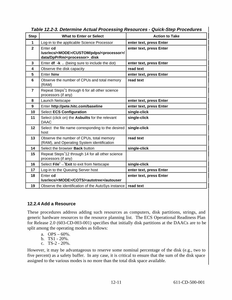
Table 12.2-3. Determine Actual Processing Resources - Quick-Step Procedures Step What to Enter or Select Action to Take
1 Log-in to the applicable Science Processor enter text, press Enter
2 Enter cd /usr/ecs/<MODE>/CUSTOM/pdps/<processor>/ data/DpPrRm/<processor>_disk
enter text, press Enter
3 Enter df -k . (being sure to include the dot) enter text, press Enter
4 Observe the disk capacity read text
5 Enter hinv enter text, press Enter
6 Observe the number of CPUs and total memory (RAM)
read text
7 Repeat Steps 1 through 6 for all other science processors (if any)
8 Launch Netscape enter text, press Enter
9 Enter http://pete.hitc.com/baseline enter text, press Enter
10 Select ECS Configuration single-click
11 Select (click on) the Asbuilts for the relevant DAAC
single-click
12 Select the file name corresponding to the desired host
single-click
13 Observe the number of CPUs, total memory (RAM), and Operating System identification
read text
14 Select the browser Back button single-click
15 Repeat Steps 12 through 14 for all other science processors (if any)
16 Select File → Exit to exit from Netscape single-click
17 Log-in to the Queuing Server host enter text, press Enter
18 Enter cd /usr/ecs/<MODE>/COTS/<autotree>/autouser
enter text, press Enter
19 Observe the identification of the AutoSys instance read text
12.2.4 Add a Resource
These procedures address adding such resources as computers, disk partitions, strings, and generic hardware resources to the resource planning list. The ECS Operational Readiness Plan for Release 2.0 (603-CD-003-001) specifies that initially disk partitions at the DAACs are to be split among the operating modes as follows:
a. OPS – 60%. b. TS1 - 20%. c. TS-2 - 20%.
However, it may be advantageous to reserve some nominal percentage of the disk (e.g., two to five percent) as a safety buffer. In any case, it is critical to ensure that the sum of the disk space assigned to the various modes is no more than the total disk space available.
12-11 611-CD-500-001

Table 12.2-4 presents (in a condensed format) the steps required to add a resource. If you are already familiar with the procedures, you may prefer to use the quick-step table. If you are new to the system, or have not performed this task recently, you should use the following detailed procedures:
1 Launch the Resource Editor GUI by executing Steps 1-10 of Section 12.2.1 (if the Resource EditorGUI is not currently running) then continue with the following steps.
2 From the Resource Editor GUI, select the type of resource to be added from the list on the Resource Type button.
3 Single-click on the New… button or select the New option from the File menu.
4 Define the resource as specified in the corresponding procedure section. a. Refer to the specified section for defining the desired type(s) of resources:
1. Disk – Section 12.2.4.1. 2. Virtual Computer – Section 12.2.4.2. 3. Real Computer – Section 12.2.4.3. 4. String – Section 12.2.4.4. 5. Autosys – Section 12.2.4.5. 6. Hardware – Section 12.2.4.6.
b. Resources should generally be added in the preceding order (due to dependencies among resources).
5 After the data have been entered, click on one of the following buttons: a. Save to save and exit. b. Cancel to exit without saving.
Table 12.2-4. Add a Resource - Quick-Step Procedures Step What to Enter or Select Action to Take
1 Launch the Resource Editor GUI Use procedure in Section 12.2.1
2 Select the type of resource from the Resource Type button
single-click
3 Select the New… button single-click
4 Make entries in the necessary fields Use procedures in Sections 12.2.4.1 through 12.2.4.6
5 Save the new resource definition single-click
12.2.4.1 Disk Partition Details GUI
1 Fill in the following fields on the Disk Partition Details GUI: a. Resource Name User-defined name for the resource. (required)
1. Example: g0spg01_disk_OPS. b. Activity System-generated default activity; can be changed by clicking on the bar
in the Activity field and then clicking on one of the available options. c. Partition Size The size of the disk partition, in megabytes. (required)
1. Although the label on the GUI implies that partition size should be entered in “blocks,” the label is erroneous. Enter the partition size in megabytes.
12-12 611-CD-500-001

d. Block Size Block size in bytes (always 1024) used for the disk. (required) e. Comments User comments on the resource.
2 After the data have been entered, click on one of the following buttons: a. Save to save and exit. b. Cancel to exit without saving.
12.2.4.2 Computer Details GUI
1 Fill in the following fields on the Computer Details GUI: a. Resource Name User-defined name for the virtual computer. (required)
1. Example: g0spg01_vc_OPS. b. Activity System-generated default activity; can be changed by clicking on the bar
in the Activity field and then clicking on one of the available options. c. Number of CPUs Number of CPUs within the virtual computer. (required) d. Total RAM The total memory for the virtual computer in megabytes.
(required) e. Operating System The operating system name/version for the computer.
(required) f. Disks A list of the disks previously defined for that site. This list of disks from
which to select is used when a disk is associated (or disassociated) with the computer. After items are highlighted, arrow buttons will move items from this list to Associated Disks or from the list of Associated Disks to the Disk list.
g. Associated Disks Disks in this list are associated with the computer. h. Comments User comments on the resource.
2 After the data have been entered, click on one of the following buttons: a. Save to save and exit. b. Cancel to exit without saving.
12.2.4.3 Real Computer Details GUI
1 Fill in the following fields on the Real Computer Details GUI: a. Resource Name User-defined name for the real resource. (required)
1. Example: g0spg01. b. Activity System-generated default activity; can be changed by clicking on the bar
in the Activity field and then clicking on one of the available options. c. Computers A list of the virtual computers previously defined for that site.
This list of virtual computers from which to select is used when a virtual computer is associated (or disassociated) with the real computer. After items are highlighted, arrow buttons will move items from this list to Associated Computers or from the list of Associated Computers to the Computers list.
d. Associated Computers Virtual computers in this list are associated with the real computer.
e. Comments User comments on the resource.
2 After data have been entered, click on one of the following buttons: a. Save to save and exit. b. Cancel to exit without saving.
12-13 611-CD-500-001
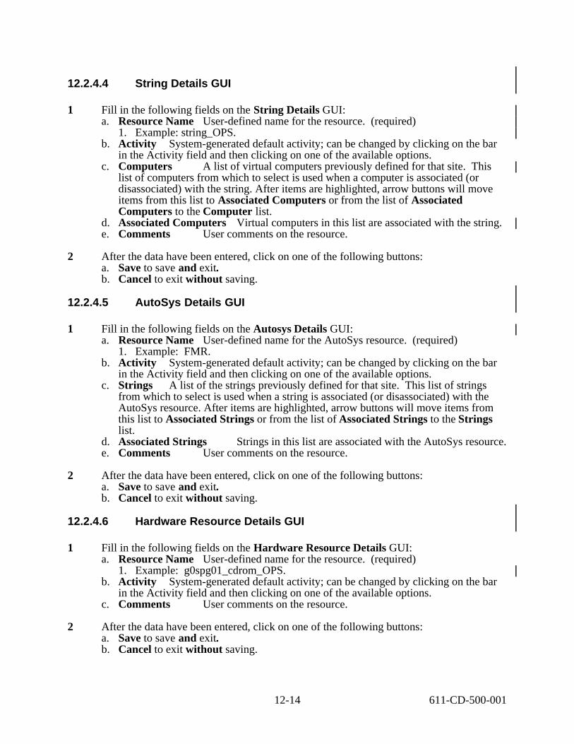
12.2.4.4 String Details GUI
1 Fill in the following fields on the String Details GUI: a. Resource Name User-defined name for the resource. (required)
1. Example: string_OPS. b. Activity System-generated default activity; can be changed by clicking on the bar
in the Activity field and then clicking on one of the available options. c. Computers A list of virtual computers previously defined for that site. This
list of computers from which to select is used when a computer is associated (or disassociated) with the string. After items are highlighted, arrow buttons will move items from this list to Associated Computers or from the list of Associated Computers to the Computer list.
d. Associated Computers Virtual computers in this list are associated with the string. e. Comments User comments on the resource.
2 After the data have been entered, click on one of the following buttons: a. Save to save and exit. b. Cancel to exit without saving.
12.2.4.5 AutoSys Details GUI
1 Fill in the following fields on the Autosys Details GUI: a. Resource Name User-defined name for the AutoSys resource. (required)
1. Example: FMR. b. Activity System-generated default activity; can be changed by clicking on the bar
in the Activity field and then clicking on one of the available options. c. Strings A list of the strings previously defined for that site. This list of strings
from which to select is used when a string is associated (or disassociated) with the AutoSys resource. After items are highlighted, arrow buttons will move items from this list to Associated Strings or from the list of Associated Strings to the Strings list.
d. Associated Strings Strings in this list are associated with the AutoSys resource. e. Comments User comments on the resource.
2 After the data have been entered, click on one of the following buttons: a. Save to save and exit. b. Cancel to exit without saving.
12.2.4.6 Hardware Resource Details GUI
1 Fill in the following fields on the Hardware Resource Details GUI: a. Resource Name User-defined name for the resource. (required)
1. Example: g0spg01_cdrom_OPS. b. Activity System-generated default activity; can be changed by clicking on the bar
in the Activity field and then clicking on one of the available options. c. Comments User comments on the resource.
2 After the data have been entered, click on one of the following buttons: a. Save to save and exit. b. Cancel to exit without saving.
12-14 611-CD-500-001

12.2.5 Modify a Resource
Table 12.2-5 presents (in a condensed format) the steps required to modify a resource. If you are already familiar with the procedures, you may prefer to use the quick-step table. If you are new to the system, or have not performed this task recently, you should use the following detailed procedures:
1 Launch the Resource Editor GUI by executing Steps 1-10 of Section 12.2.1 (if the Resource Editor GUI is not currently running) then continue with the following steps.
2 From the list of resources displayed on the Resource Editor GUI, single-click on the resource to be modified.
3 Single-click on the Modify… button to access the appropriate Details GUI.
4 Make the modifications. a. For field descriptions, refer to Sections 12.2.4.1 through 12.2.4.6.
5 After the data have been entered, click on one of the following buttons: a. Save to save and exit. b. Cancel to exit without saving.
Table 12.2-5. Modify a Resource - Quick-Step Procedures Step What to Enter or Select Action to Take
1 Launch the Resource Editor GUI Use procedure in Section 12.2.1
2 Select the resource to be modified single-click
3 Select the Modify… button single-click
4 Make the modifications Use procedures in Sections 12.2.4.1 through 12.2.4.6
5 Save the modified resource definition single-click
12.2.6 Delete a Resource
Table 12.2-6 presents (in a condensed format) the steps required to delete a resource. If you are already familiar with the procedures, you may prefer to use the quick-step table. If you are new to the system, or have not performed this task recently, you should use the following detailed procedures:
1 Launch the Resource Editor GUI by executing Steps 1-10 of 12.2.1 (if the Resource Editor GUI is not currently running) then continue with the following steps.
2 From the list of resources displayed on the Resource Editor GUI, single-click on the resource to be deleted.
3 Single-click on the Delete button. a. A dialogue box pops up, to verify whether the resource is really to be deleted.
12-15 611-CD-500-001
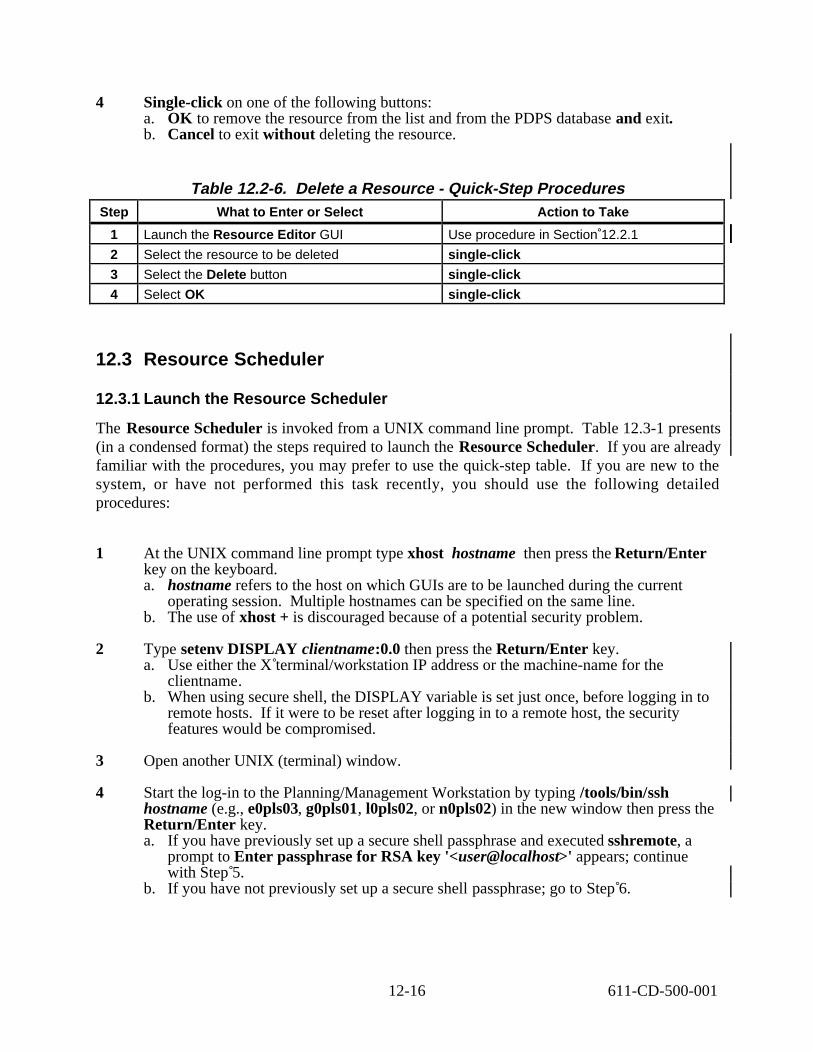
4 Single-click on one of the following buttons: a. OK to remove the resource from the list and from the PDPS database and exit. b. Cancel to exit without deleting the resource.
Table 12.2-6. Delete a Resource - Quick-Step Procedures Step What to Enter or Select Action to Take
1 Launch the Resource Editor GUI Use procedure in Section 12.2.1
2 Select the resource to be deleted single-click
3 Select the Delete button single-click
4 Select OK single-click
12.3 Resource Scheduler
12.3.1 Launch the Resource Scheduler
The Resource Scheduler is invoked from a UNIX command line prompt. Table 12.3-1 presents (in a condensed format) the steps required to launch the Resource Scheduler. If you are already familiar with the procedures, you may prefer to use the quick-step table. If you are new to the system, or have not performed this task recently, you should use the following detailed procedures:
1 At the UNIX command line prompt type xhost hostname then press the Return/Enter key on the keyboard. a. hostname refers to the host on which GUIs are to be launched during the current
operating session. Multiple hostnames can be specified on the same line. b. The use of xhost + is discouraged because of a potential security problem.
2 Type setenv DISPLAY clientname:0.0 then press the Return/Enter key. a. Use either the X terminal/workstation IP address or the machine-name for the
clientname. b. When using secure shell, the DISPLAY variable is set just once, before logging in to
remote hosts. If it were to be reset after logging in to a remote host, the security features would be compromised.
3 Open another UNIX (terminal) window.
4 Start the log-in to the Planning/Management Workstation by typing /tools/bin/ssh hostname (e.g., e0pls03, g0pls01, l0pls02, or n0pls02) in the new window then press the Return/Enter key. a. If you have previously set up a secure shell passphrase and executed sshremote, a
prompt to Enter passphrase for RSA key '<user@localhost>' appears; continue with Step 5.
b. If you have not previously set up a secure shell passphrase; go to Step 6.
12-16 611-CD-500-001
5 If a prompt to Enter passphrase for RSA key '<user@localhost>' appears, type your Passphrase then press the Return/Enter key. a. Go to Step 7.
6 At the <user@remotehost>’s password: prompt type your Password then press the Return/Enter key.
7 In the terminal window, at the command line prompt, enter:
cd /usr/ecs/<MODE>/CUSTOM/utilities a. <MODE> identifies the current operating mode
1. TS1 - Science Software Integration and Test (SSI&T) 2. TS2 - New Version Checkout 3. OPS - Normal Operations
b. “utilities” is the directory containing the Resource Planning scripts.
8 Set the necessary environment variables by entering:
setenv ECS_HOME /usr/ecs/ a. Application home environment is entered. b. When logging in as a system user (e.g., cmshared), the ECS_HOME variable may be
set automatically so it may not be necessary to set it manually.
9 Enter EcPlRpAllStart <MODE> <application_id> a. The Resource Planning background processes are launched. b. The application_id or MSGSRV_ID is a number from 1 to 5. It identifies the
message service in use so messages can be directed to the proper message handler GUI. Consequently, it is a good idea to use the same application_id consistently during a resource planning session.
10 Enter EcPlRpSiStart <MODE> <application_id> a. The Resource Scheduler is launched. b. The Resource Scheduler Graphical User Interface (GUI) is accessed. The GUI
displays the Resource Reservation List, activity type, and a series of buttons that enable the following operations: 1. New... Create a resource reservation request. (Section 12.3.2) 2. Modify... Edit or review the details of an existing resource reservation
request. (Section 12.3.3) 3. Approve Used to indicate that the resource reservation request(s) has (have)
been validated and a draft resource plan can be created. Clicking on this button causes the Planning Subsystem to determine whether there are conflicts between this resource reservation and other reservations. The Planning Subsystem detects conflicts and reports them to the operator. (Section 12.3.5)
4. Commit globally Commit all “approved” resource reservations; at this point the ground events will be accessible by the production planning software. (Section 12.3.6)
5. Time Line Display a timeline-oriented view of the resource plan. (Section 12.3.7)
6. ReportThe Report option is disabled. The reports have been deleted from the system requirements.
12-17 611-CD-500-001

Table 12.3-1. Launch the Resource Scheduler - Quick-Step Procedures Step What to Enter or Select Action to Take
1 Log in to the ECS System using secure shell enter text, press Enter
2 Enter cd /usr/ecs/<MODE>/CUSTOM/utilities enter text, press Enter
3 Set the environment variables enter text, press Enter
4 Enter EcPlRpAllStart <MODE> <application_id>
enter text, press Enter
5 Enter EcPlRpSiStart <MODE> <application_id> enter text, press Enter
12.3.2 Create a Resource Reservation Request
Table 12.3-2 presents (in a condensed format) the steps required to create a Resource Reservation Request. If you are already familiar with the procedures, you may prefer to use this quick-step table. If you are new to the system, or have not performed this task recently, you should use the following detailed procedures.
1 Launch the Resource Scheduler GUI by executing Steps 1-10 of Section 12.3.1 (if the GUI is not currently running) then continue with the following steps.
2 From the Resource Scheduler GUI, click on the New... button to access the Resource Reservation Request Edit/Definition GUI.
3 Enter Resource Request Identification Information into the displayed fields. Press [TAB] to move from field to field. NOTE: Data that is system-generated is identified. a. Request Name User-provided name for the resource request. (required) b. Edited Date System-generated date of request entry. c. Originator User-provided name of the authorized user preparing the resource
request. d. Sponsor User-provided name of the individual who is to review and validate the
Resource Request; the subject-matter-expert. (required)
4 Enter Resource Scheduling Information into the displayed fields. Press [TAB] to move from field to field. a. Activity Type User-provided description of the type of activity; selected by the
user from a selection list of valid options. (required) b. Priority User-provided priority for the activity. Use the slider to select the
appropriate priority on a scale from 0 to 100. 1 denotes the highest priority and 100 designates the lowest.
c. Description User-provided description of the activity for which the resource is required. (required)
d. Resource... See Section 12.3.2.1, below. (required) e. Interval... Not applicable to new resource reservation requests; may be applicable
when editing a resource reservation request. See Section 12.3.2.3, below. (Section 12.3.2.2 related.)
5 Enter Duration Information into the displayed fields to define the period over which the resource is required. Press [TAB] to move from field to field. a. Start Date User-provided start date of the resource request period. Enter in
MM/DD/YYYY format. (required)
12-18 611-CD-500-001

1
2
3
4
5
6
7
8
b. Start Time User-provided start time of the resource request. Enter in hh:mm:ss format. (required)
c. Start Time User-provided start time of the resource request. Enter in hh:mm:ss format. (required)
d. Stop Date User-provided stop date of the resource request period. Enter in MM/DD/YYYY format. If a reservation is to be repeated over some frequency (see below), the stop date specifies the end date in the date range of the reservation request. (required)
e. Stop TimeUser-provided stop time of the resource request. Enter in hh:mm:ss format. (required)
f. Frequency See Section 12.3.1.3, below. (Section 12.3.1.4 related.)
6 Enter comments concerning the resource reservation request in the Comment field.
7 After data is entered, click on the appropriate button(s): a. Save to save data. b. Clear to clear entries. Once cleared, the entries are deleted from the system. c. Cancel to exit screen without saving the request.
8 The resource reservation must be “saved” prior to validating or rejecting. After the request has been saved, it can then be validated or rejected. The selections Validated and Rejected are further discussed in Section 12.3.3.
Table 12.3-2. Create a Resource Reservation - Quick-Step Procedures Step What to Enter or Select Action to Take
Launch the Resource Scheduler GUI Use procedure in Section 12.3.1
New… button single-click
Resource identification information enter text, press tab
Resource scheduling information enter text, press tab
Duration information enter text, press tab
Comments enter text, press tab
Save data single-click
Exit single-click
12.3.2.1 Selecting Resources...
Clicking on the Resource… button accesses a Resources Selection screen. The Request Name is blank and is to remain empty when creating a new resource reservation request. This screen provides a pair of lists: Resources and Selected Resources. The Resources list itemizes available resources. The Selected Resources list itemizes those resources that have been selected for incorporation into the resource reservation. The user selects the desired resource(s) and, using the arrow buttons, moves the resource(s) from one list to the other list.
1 Click on your selections in the list and click on the desired arrow to move resources between the Resources and Selected Resources lists.
2 Click OK to save the selections and exit the screen.
12-19 611-CD-500-001

3 Click Cancel to exit the screen without saving changes.
12.3.2.2 Selecting Frequency
The Frequency option button provides the mechanism that allows the user to specify whether the resource reservation request describes a one-time event or a recurring event. Clicking on Frequency allows the user to specify options for periodic resource requests; that is, to specify the frequency of occurrence of a repeating resource need. Several options for expressing the frequency are available in the Frequency selection list box combined with a text field that provides a qualifier (i.e., number of days) for the Every_?_days selection only. The frequency specified defaults to Once to indicate that the resource need covers the entire time period covered by ‘Start Time’ and ‘Stop Time’ (a single Start Date is required for this option only). Other options are identified in Table 12.3-3. The dates generated are inserted in the Selected Intervals list box, described in Section 12.3.2.3, below.
12.3.2.3 Selecting Intervals...
The Interval… button provides the mechanism to tailor a Frequency-based request by overriding selected intervals (Note: the initial resource reservation must be saved prior to tailoring frequency-based requests.). Selecting the Interval… button, displays a secondary screen that provides a pair of lists: Unselected Intervals and Selected Intervals. Unselected Intervals lists the dates that will not be reserved for the reservation request. Selected Intervals lists the dates that will be included for the request. The Selected Interval dates are automatically generated by the system, based upon the Frequency option selected (see Section 12.3.2.2, above). You can move them to or from the Unselected Intervals list to modify the automated list. Dates are moved from one list to the other by selecting the dates and using the arrow keys. The Request Name is also displayed.
1 Click on your selections and click on the desired arrow to move dates between the Selected Intervals and Unselected Intervals lists.
2 Click OK to save your selections and exit the screen.
3 Click Cancel to exit the screen without saving changes.
12-20 611-CD-500-001

--
--
--
--
--
--
--
--
--
Table 12.3-3. Frequency Qualifiers Frequency Text
Qualifier: Result:
Once The default. time and stop time for the start date specified.
Daily Resource reservation for every day, between the start date and end date, for the start time and end time specified.
Weekly Resource reservation for every week occurring on the day specified by the start date, repeated until the end date as specified.
Every_2_weeks Resource reservation occurring biweekly on the day specified by the start date, repeated until the end date as specified.
Monthly Resource reservation for every month on the start day of the month, repeated until the end date as specified.
Mon_thru_Fri Resource reservation for every Monday through Friday, between the start date and end date, for the start time and end time specified.
Mon_Wed_Fri Resource reservation for every Monday, Wednesday, and Friday, between the start date and end date, for the start time and end time specified.
Tues_Thurs Resource reservation for every Tuesday and Thursday, between the start date and end date, for the start time and end time specified.
Every_?_days n Resource reservation for every n days, between the start date and end date, for the start time and end time specified.
Weekend Resource reservation for every Saturday and Sunday, between the start date and end date, for the start time and end time specified.
Resource reservation covering the period from the start
12.3.3 Edit a Resource Reservation Request
Table 12.3-4 presents (in a condensed format) the steps required to edit a Resource Reservation Request. If you are already familiar with the procedures, you may prefer to use the quick-step table. If you are new to the system, or have not performed this task recently, you should use the following detailed procedures:
1 Launch the Resource Scheduler GUI by executing Steps 1-10 of Section 12.3.1, if not currently running, then continue with the following steps.
2 From the Resource Scheduler GUI, single-click on the resource reservation request to be modified.
3 Single-click on the Modify… button to access the Resource Reservation Request Edit/Definition GUI.
4 Make the modifications to affected fields. (See Section 12.3.2, above.)
12-21 611-CD-500-001
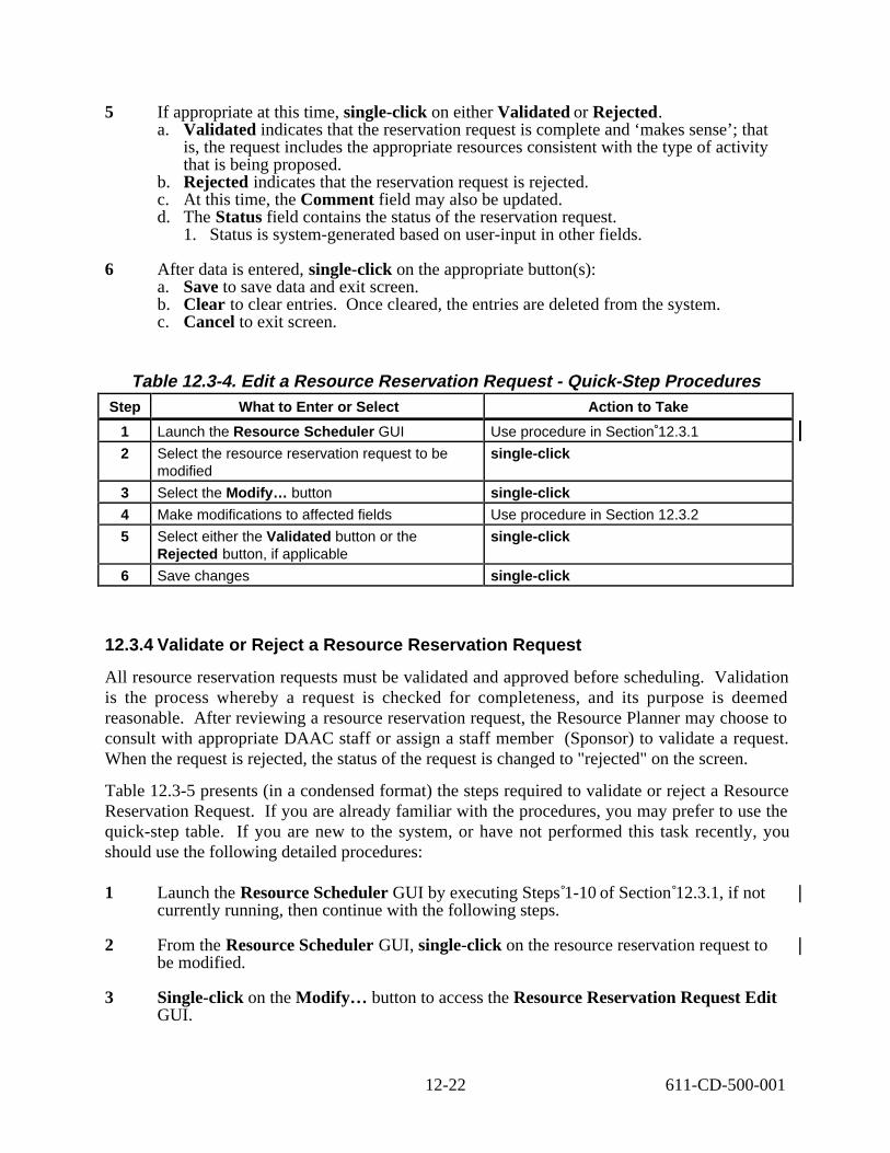
5 If appropriate at this time, single-click on either Validated or Rejected. a. Validated indicates that the reservation request is complete and ‘makes sense’; that
is, the request includes the appropriate resources consistent with the type of activity that is being proposed.
b. Rejected indicates that the reservation request is rejected. c. At this time, the Comment field may also be updated. d. The Status field contains the status of the reservation request.
1. Status is system-generated based on user-input in other fields.
6 After data is entered, single-click on the appropriate button(s): a. Save to save data and exit screen. b. Clear to clear entries. Once cleared, the entries are deleted from the system. c. Cancel to exit screen.
Table 12.3-4. Edit a Resource Reservation Request - Quick-Step Procedures Step What to Enter or Select Action to Take
1 Launch the Resource Scheduler GUI Use procedure in Section 12.3.1
2 Select the resource reservation request to be modified
single-click
3 Select the Modify… button single-click
4 Make modifications to affected fields Use procedure in Section 12.3.2
5 Select either the Validated button or the Rejected button, if applicable
single-click
6 Save changes single-click
12.3.4 Validate or Reject a Resource Reservation Request
All resource reservation requests must be validated and approved before scheduling. Validation is the process whereby a request is checked for completeness, and its purpose is deemed reasonable. After reviewing a resource reservation request, the Resource Planner may choose to consult with appropriate DAAC staff or assign a staff member (Sponsor) to validate a request. When the request is rejected, the status of the request is changed to "rejected" on the screen.
Table 12.3-5 presents (in a condensed format) the steps required to validate or reject a Resource Reservation Request. If you are already familiar with the procedures, you may prefer to use the quick-step table. If you are new to the system, or have not performed this task recently, you should use the following detailed procedures:
1 Launch the Resource Scheduler GUI by executing Steps 1-10 of Section 12.3.1, if not currently running, then continue with the following steps.
2 From the Resource Scheduler GUI, single-click on the resource reservation request to be modified.
3 Single-click on the Modify… button to access the Resource Reservation Request Edit GUI.
12-22 611-CD-500-001

4 Single-click on either Validated or Rejected. a. Validated indicates that the reservation request is complete and ‘makes sense’; that
is, the request includes the appropriate resources consistent with the type of activity that is being proposed.
b. Rejected indicates that the reservation request is rejected. c. At this time, the Comment field may also be updated. d. The Status field contains the status of the reservation request.
1. Status is system-generated based on user-input in other fields.
5 After data is entered, single-click on the appropriate button(s): a. Save to save data. b. Clear to clear entries. Once cleared, the entries are deleted from the system. c. Cancel to exit screen.
Table 12.3-5. Validate or Reject a Resource Reservation Request -Quick-Step Procedures
Step What to Enter or Select Action to Take
1 Launch the Resource Scheduler GUI Use procedure in Section 12.3.1
2 Select the resource reservation request to be modified
single-click
3 Select the Modify… button single-click
4 Select either the Validated button or the Rejected button, as appropriate
single-click
5 Save changes single-click
12.3.5 Approve a Resource Reservation Request
The Approve button is used when all reviews that are a part of the resource planning process have taken place and there are no objections to the resource usage as described by the request. Clicking on this button will verify that there are no conflicts between this resource reservation and other reservations. If conflicts are detected, a screen will pop up listing the conflicts to be addressed for resolution. Click OK to collapse the pop-up screen. Clicking on Approve generates the pop-up screen again (if conflicts exist). Approval occurs after a request has been validated and the event time is acceptable.
Table 12.3-6 presents (in a condensed format) the steps required to approve a Resource Reservation Request. If you are already familiar with the procedures, you may prefer to use the quick-step table. If you are new to the system, or have not performed this task recently, you should use the following detailed procedures:
1 Launch the Resource Reservation GUI by executing Steps 1-10 of Section 12.3.1, then continue with the following steps.
2 From the Resource Scheduler GUI, single-click on the resource reservation request to be approved.
3 Single-click on the Approve button.
12-23 611-CD-500-001

a. If there are no resource conflicts resulting from the approval of the resource reservation request, a pop-up dialogue box appears bearing the message, “Success to approve reservation Name: [name].”
b. If there are resource conflicts resulting from the attempt to approve the resource reservation request, a pop-up dialogue box appears indicating that the approval failed and making reference to the Message Handler GUI for further information.
4 Single-click on the OK button to collapse the pop-up dialogue box. a. If there are no resource conflicts to be resolved, the entry in the Status column of the
Resource Scheduler GUI indicates that the request is "Approved" (changes from “Validated”). [End of procedure.]
b. If there are resource conflicts to be resolved, the entry in the Status column of the Resource Scheduler GUI indicates that the request has "Conflicts" (changes from “Validated”). [Continue with Step 5.]
5 If there are resource conflicts to be resolved, examine the information displayed on the Resource Scheduler GUI. a. Although the pop-up dialogue box makes reference to the Message Handler GUI for
further information, no relevant data seems to be displayed there. Therefore, it is more appropriate to check for conflicts in the duration and frequency information for the resource reservation requests displayed on the Resource Scheduler GUI. When more than one resource reservation request is scheduled for the same date and time, there may be a conflict (if the same resource is specified in the requests).
b. It may be necessary to examine individual resource reservation requests in detail. If so, use the procedure for Editing a Resource Reservation Request (Section 12.3.3).
6 If necessary, consult with the resource requester(s), Resource Manager and other personnel to determine which resource reservation request(s) to modify or delete in order to create a conflict-free resource plan.
7 If applicable, go to the procedure for Deleting a Resource Reservation Request (Section 12.3.8) and delete resource reservation request(s) as necessary to resolve the conflicts.
8 If applicable, go to the procedure for Editing a Resource Reservation Request (Section 12.3.3) and modify/validate resource reservation request(s) as necessary to resolve the conflicts.
9 If applicable, return to Step 2 to approve a modified resource reservation request. a. The modified procedure must have been “validated.” If necessary, refer to the
procedure for Validating or Rejecting a Resource Reservation Request (Section 12.3.4).
10 From the File menu, select Exit.
12-24 611-CD-500-001

Table 12.3-6. Approve a Resource Reservation Request - Quick-Step Procedures Step What to Enter or Select Action to Take
1 Launch the Resource Scheduler GUI Use procedure in Section 12.3.1
2 Select the resource reservation request to be approved
single-click
3 Select the Approve button single-click
4 Select the OK button single-click
5 If there are resource conflicts to be resolved, examine the information displayed on the Resource Scheduler GUI
observe
6 Resolve conflicts as necessary Use procedures in Sections 12.3.8 and 12.3.3
7 Select File → Exit single-click
12.3.6 Commit Resource Reservation Requests
Clicking on the Commit globally button commits all approved reservation requests and makes them accessible to Production Planning.
Table 12.3-7 presents (in a condensed format) the steps required to commit a Resource Reservation Request. If you are already familiar with the procedures, you may prefer to use the quick-step table. If you are new to the system, or have not performed this task recently, you should use the following detailed procedures:
1 Launch the Resource Scheduler GUI by executing Steps 1-10 of Section 12.3.1, then continue with the following steps.
2 From the Resource Scheduler GUI, single-click on the Commit globally button. a. Status shows Committed for all previously Approved requests.
3 From the File menu, select Exit.
Table 12.3-7. Commit Resource Reservation Requests - Quick-Step Procedures Step What to Enter or Select Action to Take
1 Launch the Resource Scheduler GUI Use procedure in Section 12.3.1
2 Select the Commit globally button single-click
3 Select File → Exit single-click
12.3.7 Review the Resource Timeline
The Resource Planning utilities allow the user to view the Resource Plan as a timeline. Table 12.3-8 presents (in a condensed format) the steps required to review the Resource Timeline. If you are already familiar with the procedures, you may prefer to use the quick-step
12-25 611-CD-500-001

table. If you are new to the system, or have not performed this task recently, you should use the following detailed procedures:
1 Launch the Resource Scheduler GUI by executing Steps 1-10 of Section 12.3.1, then continue with the following steps.
2 From the Resource Scheduler GUI single-click on the Timeline button. a. The Resource Timeline GUI is displayed. b. The display represents a set of resources, arranged along the left side of the screen
and some period of time as indicated across the top edge of the screen. c. The use of a resource over a period of time is represented by one or more ‘resource
reservation’ bars across the screen. d. A bar represents a time period during which a resource reservation has been planned
for the resource. 1. Each bar has the name of the resource reservation and a brief description. 2 . For time periods during which a reservation has not been placed against a
resource, that resource is planned for use by a default activity, e.g., science processing computers will be used for science processing unless a reservation has been placed against that resource .
3. Scroll bars allow scrolling up and down through the full list of resources and left and right in time.
3 Adjust the Resource Timeline window size and the view of the timeline as necessary using the mouse. a. Grab a corner of the timeline window with the cursor and resize the window as
desired. b. Scroll up or down through the full list of resources. c. Scroll left or right to go backward or forward in time.
4 If a different time scale (start and end dates and times) is desired, perform Steps 5 through 7; otherwise, go to Step 8.
5 Select Display → Change Time Scale from the pull-down menu: a. The plan window edit window is displayed.
6 Type date and time for the desired start and end times (in DD MMM YYYY hh:mm:ss format) in the Plan Win Start and Plan Win End fields of the plan window edit window.
7 When the appropriate date and time have been entered, click on the appropriate button from the following selections: a. OK - to accept the changes and dismiss the plan window edit window. b. Apply - to accept the changes without dismissing the plan window edit window. c. Cancel - to cancel the changes and dismiss the plan window edit window.
8 If a different time span is desired, click and hold on the Show option button and select (highlight then release the mouse button) the desired time span from the option menu that is displayed: a. 1 hr
12-26 611-CD-500-001

b. 4 hr c. 8 hr d. 12 hr e. 24 hr f. 48 hr g. 4 day h. 1 week i. 2 week j. 1 month k. full scale
9 If no resources are displayed on the GUI or if different resources should be displayed, perform Steps 10 through 14; otherwise, go to Step 15.
10 Select Display → Change resources from the pull-down menu: a. The Resource edit window is displayed.
11 If adding resource(s) from the Available Resources list to the Viewed Resources list, select (highlight) the resource(s) to be added, then click on the Add button to move the resource(s) to the Viewed Resources list. a. Highlighted resource(s) appear(s) on the Viewed Resources list.
12 If deleting resource(s) from the Viewed Resources list, select (highlight) the resource(s) to be removed, then click on the Del button to remove the resource(s) from the Viewed Resources list. a. Highlighted resource(s) disappear(s) from the Viewed Resources list.
13 If changing the order in which resources are listed in the Viewed Resources list, select (highlight) the resource to be moved, then click on the up or down arrow as necessary to reposition the selected resource. a. Highlighted resource changes position in the Viewed Resources list.
14 When the Viewed Resources list contains the desired set of resources, click on the appropriate button from the following selections: a. OK - to accept the changes and dismiss the Resource edit window. b. Apply - to accept the changes without dismissing the Resource edit window. c. Cancel - to cancel the changes and dismiss the Resource edit window.
15 If different color coding of the timeline is desired, perform Steps 16 through 20; otherwise, go to Step 21.
16 Select Display → Change colors from the pull-down menu: a. The Color Selections window is displayed.
17 Click on the name of one of the resource reservations to be recolored. a. The resource reservation is highlighted.
18 Click on the desired color (in the color palette) to be applied to the highlighted resource reservation.
19 Repeat Steps 17 and 18 as necessary.
12-27 611-CD-500-001

1
2
3
4
5
6
7
8
9
10
11
12
13
14
15
16
17
18
19
20 When the appropriate color changes have been made, click on the appropriate button from the following selections: a. OK - to accept the changes and dismiss the Color Selections window. b. Apply - to accept the changes without dismissing the Color Selections window. c. Cancel - to cancel the changes and dismiss the Color Selections window.
21 Observe the resource reservation information displayed on the Resource Timeline GUI.
22 Repeat the previous steps as necessary.
23 If it becomes necessary to exit from the timeline GUI, select File → Quit from the pulldown menu.
Table 12.3-8. Review the Resource Timeline - Quick-Step Procedures Step What to Enter or Select Action to Take
Launch the Resource Scheduler GUI Use procedure in Section 12.3.1
Select the Timeline button single-click
Select Display → Change Time Scale window single-click
Enter plan window start date and time enter text
Enter plan window end date and time enter text
Select Ok single-click
Select time span single-click
Select Display → Change Resources single-click
Select resources to be viewed single-click resources
Select Add single-click
Select viewed resource to be reordered single-click resource
Reorder viewed resources using up/down arrows single-click
Select Ok single-click
Select Display → Change Colors single-click
Select resource reservation single-click
Select new color for resource reservation single-click
Select Ok single-click
Observe the resource reservation information observe
Select File → Quit to quit the timeline single-click
12.3.8 Delete a Resource Reservation Request
Table 12.3-9 presents (in a condensed format) the steps required to delete a resource reservation request. If you are already familiar with the procedures, you may prefer to use the quick-step table. If you are new to the system, or have not performed this task recently, you should use the following detailed procedures:
12-28 611-CD-500-001

1 Launch the Resource Scheduler GUI by executing Steps 1-10 of Section 12.3.1, then continue with the following steps.
2 From the Resource Scheduler GUI, highlight (click on) the resource reservation request you want to delete.
3 Select Delete from the File menu. a. Status shows "Deleted" for the selected request. The resource reservation request is
not removed from the database at this point and is available for future reporting but will have no impact on resource planning. Resource reservations are removed from the Resource reservations (PDPS) database through routine database maintenance activities.
4 To exit, select Exit from the File menu.
Table 12.3-9. Delete a Resource Reservation Request - Quick-Step Procedures Step What to Enter or Select Action to Take
1 Launch the Resource Scheduler GUI Use procedure in Section 12.3.1
2 Select the resource reservation request to be deleted
single-click
3 Select File → Delete single-click
4 Select File → Exit single-click
12.4 Shut Down Resource Planning Applications
When resource planning activities have been completed, the Message Handler, System Name Server, and Resource Model should be shut down to eliminate unneeded processes and allow other operators to gain access to the resource planning applications. If any of the three processes remains active, it is likely to interfere with subsequent attempts to launch resource planning applications.
Shutting down resource planning applications starts with the assumption that the Resource Editor GUI and the Resource Scheduler GUI have been launched and the GUIs are currently being displayed.
Table 12.4-1 presents (in a condensed format) the steps required to shut down resource planning applications. If you are already familiar with the procedures, you may prefer to use the quickstep table. If you are new to the system, or have not performed this task recently, you should use the following detailed procedures:
1 To quit the Resource Editor GUI when resource planning activities have been completed select File → Exit from the GUI’s pull-down menu. a. The Resource Editor GUI disappears.
2 To quit the Resource Scheduler GUI when resource planning activities have been completed select File → Exit from the GUI’s pull-down menu.
12-29 611-CD-500-001

a. The Resource Scheduler GUI disappears unless there are resource reservation requests with a status of “approved”.
b. If there are any resource reservation requests with a status of “approved” listed on the Resource Scheduler GUI, a Close Application pop-up dialogue box is displayed with a message “Status of the listed reservations” and a list of the resource reservation requests with “approved” status.
3 If the Close Application pop-up dialogue box is displayed, click on the appropriate button from the following selections: a. Ok - to quit the Resource Scheduler GUI and dismiss the dialogue box. b. Cancel - to dismiss the dialogue box and return to the Resource Scheduler GUI.
4 After quitting the Resource Editor/Resource Scheduler GUI(s) click in the UNIX window used to start the resource planning applications.
5 Type EcPlRpSlayAll <MODE> <application_id> then press Return/Enter to shut down the Message Handler, System Name Server, and Resource Model. a. The Message Handler GUI disappears.
6 Type ps -ef | grep <MODE> then press Return/Enter to obtain a list of active processes in the specified mode. a. A list of active processes in the specified mode is displayed. b. If an error message is received when ps -ef | grep <MODE> is entered, type
ps -auxwww | grep <MODE> then press Return/Enter.
7 Examine the list of processes running in the specified mode to determine whether the Message Handler, System Name Server, and Resource Model processes have actually been shut down. a. None of the following processes should be active:
1. EcPlRpRe 2. EcPlRpSi 3. EcPlRpTl 4. EcPlMsh 5. EcPlSns 6. EcPlRpRm
8 If any of the specified processes [especially the Message Handler, System Name Server, and/or Resource Model process(es)] is/are still active, type kill -15 process_id1 [process_id2] [process_id3] […] to terminate the active process(es).
9 Repeat Steps 6 through 8 as necessary.
12-30 611-CD-500-001

Table 12.4-1. Shut Down Resource Planning Applications -Quick-Step Procedures
Step What to Enter or Select Action to Take
1 Select File → Exit to quit the Resource Editor GUI
single-click
2 Select File → Exit to quit the Resource Scheduler GUI
single-click
3 Select OK single-click
4 Select the UNIX window single-click
5 Enter EcPlRpSlayAll <MODE> <application_id>
enter text, press Enter
6 Enter ps -ef | grep <MODE> enter text, press Enter
7 Verify that the resource planning processes have actually been shut down
observe
8 Enter kill -15 process_id1 [process_id2] [process_id3] […] to terminate active process(es)
enter text, press Enter
12-31 611-CD-500-001

This page intentionally left blank.
12-32 611-CD-500-001

1
2
3
4
5
6
7
13. Production Planning
The Planning Subsystem is responsible for supporting site operations in developing a production plan based on locally defined strategy. Production Planning involves creation of Production Requests using the Production Request Editor and the scheduling of the Production Requests using the Production Workbench. The Production Planner issues commands to initiate plan creation and plan activation.
The Planning Subsystem submits Data Processing Requests (DPRs). A DPR has the information needed by Processing, including Product Generation Executive (PGE)-related information. Each DPR defines a set of related processing jobs.
13.1 Production Request Editor
From the Production Request Editor, the Production Planner can create new production requests, modify or delete production requests, and review or delete data processing requests.
Each procedure outlined has an Activity Checklist table that provides an overview of the task to be completed. The outline of the Activity Checklist is as follows:
Column one - Order shows the order in which tasks should be accomplished.
Column two - Role lists the Role/Manager/Operator responsible for performing the task.
Column three - Task provides a brief explanation of the task.
Column four - Section provides the Procedure (P) section number or Instruction (I) section number where details for performing the task can be found.
Column five - Complete? is used as a checklist to keep track of which task steps have been completed.
The following Activity Checklist, Table 13.1-1, provides an overview of the Production Planning process.
Table 13.1-1. Production Request - Activity Checklist Order Role Task Section Complete?
Production Planner Launch the Production Request Editor (P) 13.1.1
Production Planner Create New Production Request (P) 13.1.2
Production Planner Edit/Modify Production Request (P) 13.1.3
Production Planner Delete Production Request (P) 13.1.4
Production Planner Review Data Processing Requests (P) 13.1.5
Production Planner Delete DPRs (P) 13.1.6
Production Planner Re-Generate Granules Affected by Loss of Files from the Archive
(P) 13.1.7
13-1 611-CD-500-001

NOTE: The procedures that follow are written under the assumption that PGEs have been previously created and are available for use with the same rule criteria that you are attempting to use.
13.1.1 Launch the Production Request Editor
The Production Request Editor is invoked from a UNIX command line prompt. Table 13.1-2 presents (in a condensed format) the steps required to launch the Production Request Editor. If you are already familiar with the procedures, you may prefer to use this quick-step table. If you are new to the system, or have not performed this task recently, you should use the following detailed procedures.
1 At the UNIX command line prompt enter:
xhost <hostname> a. <hostname> refers to the host on which GUI is to be launched during the current
operating session. Multiple hostnames can be specified on the same line. b. The use of xhost + is discouraged because of a potential security problem.
2 In the Terminal window, at the command line prompt, enter:
setenv DISPLAY <clientname>:0.0 a. Use either the X terminal/workstation IP address or the machine-name for the
clientname. b. When using secure shell, the DISPLAY variable is set just once, before logging in to
remote hosts. If it were to be reset after logging in to a remote host, the security features would be compromised.
3 Open another UNIX (terminal) window.
4 In the terminal window, at the command line prompt, start the log-in to the Planning/Management Workstation by entering:
/tools/bin/ssh <hostname> a. Examples of hostnames include e0pls03, g0pls01, l0pls02, n0pls02. b. If you receive the message, “Host key not found from the list of known hosts. Are
you sure you want to continue connecting (yes/no)?” enter yes (“y” alone will not work).
c. If you have previously set up a secure shell passphrase and executed sshremote, a prompt to Enter passphrase for RSA key '<user@localhost>' appears; continue with Step 5.
d. If you have not previously set up a secure shell passphrase, go to Step 6.
5 If a prompt to Enter passphrase for RSA key '<user@localhost>' appears, enter:
<Passphrase> a. Go to Step 7.
6 At the <user@remotehost>’s password: prompt enter:
<Password>
13-2 611-CD-500-001

7 In the terminal window, at the command line, enter:
cd /usr/ecs/<MODE>/CUSTOM/utilities a. <MODE> is current mode of operation.
1. TS1 - Science Software Integration and Test (SSI&T) 2. TS2 - New Version Checkout 3. OPS - Normal Operations
b. “utilities” is the directory containing the Planning Subsystem start-up scripts.
8 Set the application environment variables by entering:
setenv ECS_HOME /usr/ecs/ a. Application home environment is entered b. When logging in as a system user (e.g., cmshared), the ECS_HOME variable may be
set automatically so it may not be necessary to set it manually.
9 Start the Production Request Editor by entering:
EcPlPRE_IFStart <MODE> a. The Production Request Editor is launched.
Table 13.1-2. Launch the Production Request Editor - Quick-Step Procedures Step What to Enter or Select Action to Take
1 Log in to the Planning host using secure shell enter text, press Enter
2 Enter cd /usr/ecs/<MODE>/CUSTOM/utilities enter text, press Enter
3 Set environment variables if necessary enter text, press Enter
4 Enter EcPlPRE_IFStart <MODE> enter text, press Enter
13.1.2 Create New Production Request
The process of creating a new Production Request begins with the Production Planner starting the Production Request Editor GUI. The Production Planner specifies the PGE, duration, and comments for the new Production Request.
PRODUCTION RULES: Production Rules provide templates for Instrument Teams to describe the relationship(s) between PGEs and their input and output data. The assumption of this documentation is that the user has knowledge of the specific production rules under which the PGE was created. Listed below is a sampling of the available production rules.
Basic Temporal Input times = output times
Advanced Temporal Input and output temporal ranges can be different.
Alternate Inputs PGE is run with different inputs based on the availability of various alternate input data sets.
Optional Inputs PGE is run with specified optional inputs if available; otherwise, PGE is run without them.
13-3 611-CD-500-001

Min/Max Granules
Optional DPRs
Intermittent Activation
Metadata Checks
Metadata Query
Data Day
Spatial Query
Tiling
Closest Granule
Orbital Processing
Minimum number of input granules needed for full data coverage and maximum number of input granules to search for may be specified. Minimum and maximum number of outputs expected from the PGE may be specified.
The only DPRs executed are those for which the nonroutine key input data actually become available (i.e., are either produced in data processing or can be acquired from the archive).
Every nth DPR is activated; all other DPRs are skipped.
Run DPR only if metadata value(s) meet certain criteria.
Input granule selection is based on metadata value(s).
Input data selection is based on Data Day.
Select input(s) on the basis of the spatial coverage of another input (i.e., the key input).
Input data is chosen on the basis of Instrument Teamdefined tiles (geographic areas).
DPR is generated if a required input granule within a particular time range (rather than an exact time) is available; otherwise, no DPR is generated. (Supersedes the Most Recent Granule Production Rule)
Selection of input times is based on orbit information.
Table 13.1-3 presents (in a condensed format) the steps required to create a new production request. If you are already familiar with the procedures, you may prefer to use the quick-step table. If you are new to the system, or have not performed this task recently, you should use the following detailed procedures.
1 Launch the Production Request Editor (refer to Section 13.1.1). a. The Production Request Editor GUI is displayed.
2 Select the Production Request Editor by single-clicking on the PR Edit tab. a. The PR Edit GUI page is presented.
NOTE: If the GUI is unresponsive, always check to see if a prompt window is hidden behind the main GUI waiting for a response. Respond to the window, then continue with the Production Request Editor GUI.
3 Single-click and hold the PR Type option button to display a menu of types of production requests, move the mouse cursor to the desired selection (highlighting it), then release the mouse button. a. The following production request types are listed:
1. Routine.
13-4 611-CD-500-001

2. On-Demand [not currently available for selection].3. Reprocessing.4. Ad-hoc Reprocessing.
NOTE: The PR Name and Origination Date fields will be filled automatically when the Production Request is saved at the end of the procedure. (You do not need to fill in these fields.)
4 Enter <username> or actual name for the Originator.
5 Single-click the Priority field and enter the <Priority>, then press Tab. a. Enter a number in the range of one (1) to ten (10).
1. One (1) has the highest priority; ten (10) has the lowest priority.b. The Priority field specifies the User-Selected Priority to be included in the Data
Processing Request(s) that result(s) from the Production Request.c. User-Selected Priority is subsequently weighted according to the value specified in
the Production Strategy selected from the Planning Workbench when a ProductionPlan is created using the Production Request.
6 Single-click the PGE... button. a. The PGE GUI is displayed.
7 Select the desired PGE by single-clicking on the PGE. a. The desired PGE is highlighted.
8 Single-click the Ok button. a. The PR Edit GUI is displayed.b. The following fields are automatically filled:
1. Satellite Name.2. Instrument Name.3. PGE Name.4. PGE Version.5. Profile ID.
9 Select PGE Parameters... button. a. The PGE Parameters GUI is displayed.b. PGE parameter data are displayed in a table that has the following columns:
1. Parameter Name.2. Logical Id.3. Default Value.4. Override Value.5. Description.
10 Select the parameter (if any) with the default value to be changed by single-clicking on the Parameter Name row. a. The parameter row is highlighted.b. Only the default values can be modified.c. Modify parameter values when and as directed by the customer (e.g., MODIS) only.
11 Enter the desired value in the Parameter Mapping field and press Return. a. The new value is displayed in the Override Value column.b. Repeat Steps 10 and 11 to modify additional parameters (if applicable).
13-5 611-CD-500-001

12 Single-click on the Ok button to approve the changes. a. The PR Edit GUI is displayed.
**The procedures that follow involve the implementation of specific PRODUCTION RULES.**
MODIS uses 1) Temporal Rules, to include Basic and Advanced Temporal specifications, 2) Orbit-Based Activation and 3) Period/Calendar Specification, 4) Conditional Activation, 5) Additional inputs and 6) DataBase Query.
ASTER uses both Temporal Rules, Basic and Advanced Temporal specifications. In addition, ASTER routine processing makes use of the Optional DPRs Production Rule to schedule and execute ASTER PGEs for new data that have been archived. The Production Planner specifies the insertion time range (i.e., the time period when the desired data were archived) as opposed to the collection time (when the satellite instrument gathered the data).
MISR has primarily “orbit” based PGEs.
Multiple “production rules” can be combined to complete a PR, however, Temporal- and Orbitbased rules cannot be combined.
To execute either a Basic or Advanced Temporal Production Rule, you must complete Steps 112, specified above in 13.1.2. and specify date and time information for processing (Steps 28 and 29). Then continue processing with Step 33, etc. as necessary.
METADATA-BASED PRODUCTION RULE 13 If the PGE is subject to a metadata-based production rule and the value(s) to be checked
need(s) to be changed, single-click on the Metadata Checks… button, perform Steps 14 through 18 as applicable; otherwise go to Step 19. a. The MetadataChecks GUI page is displayed. b. The MetadataChecks GUI has an InputDataType window that lists the input data
types for the PGE. c. In addition, the MetadataChecks GUI has a metadata checks (MetaDataField-
Operator-Value-Type) window in which there is a table that lists the following information concerning each metadata check: 1. MetaDataField. 2. Operator. 3. Value. 4. Type.
d. Initial values for metadata checks are entered during SSI&T; however, it is possible to modify the values using the MetadataChecks GUI when creating a production request. 1 . Modify metadata check values when and as directed by the customer (e.g.,
MODIS) only.
14 If it is necessary to change any value(s) for metadata checks, select an input data type with a value to be changed by single-clicking on the corresponding row in the InputDataType window. a. The input data type row is highlighted.
13-6 611-CD-500-001

b. The metadata check information for the highlighted input data type is displayed in the MetaDataField-Operator-Value-Type window.
15 Select (highlight) a metadata field with a comparison value to be changed by singleclicking on the corresponding row in the MetaDataField-Operator-Value-Type window. a. The metadata field row is highlighted in the MetaDataField-Operator-Value-Type
window. b. The identity of the metadata field is displayed in the MetaDataField window.
16 Enter the new value for the metadata check in the Value field.
17 Single-click on the appropriate button from the following selections: a. OK - to approve the new value and dismiss the MetadataChecks GUI.
1. The Production Request - PR Edit GUI is displayed. 2. Go to Step 19.
b. Apply - to approve the new value without dismissing the MetadataChecks GUI. 1. Go to Step 18.
c. Cancel - to return to the Production Request - PR Edit GUI without saving the new value. 1. The Production Request - PR Edit GUI is displayed. 2. Go to Step 19.
18 If any additional value(s) to be checked need to be changed, repeat Steps 14 through 17 as necessary.
13-7 611-CD-500-001

ALTERNATE INPUTS PRODUCTION RULE 19 If the PGE is subject to the Alternate Inputs Production Rule and the timer settings or
the order of alternate inputs need to be changed, single-click on the Alternate Input Values… button and perform Steps 20 through 25 as applicable; otherwise go to Step 26. a. The AlternateInputValues GUI page is displayed. b. The AlternateInputValues GUI has an AlternateListName window that lists the
applicable alternate inputs. c. In addition, the AlternateInputValues GUI has an alternate input (Order-
DataType-LogicalID-Timer) window in which there is a table that lists the following information concerning each alternate input: 1. Order. 2. DataType. 3. LogicalID. 4. Timer.
d. The initial set-up for alternate inputs is entered during SSI&T; however, it is possible to modify the set-up using the AlternateInputValues GUI when creating a production request.
20 If it is necessary to change timer settings or the order of alternate inputs, first select (highlight) an alternate input to be changed by single-clicking on the corresponding row in the AlternateListName window. a. The alternate input row is highlighted. b. Information concerning the highlighted alternate input is displayed in the Order-
DataType-LogicalID-Timer window.
21 Select (highlight) an alternate input with timer settings or the order of alternate inputs to be changed by single-clicking on the corresponding row in the Order-DataType-LogicalID-Timer window. a. Alternate input row is highlighted in the Order-DataType-LogicalID-Timer
window. b. The data type of the alternate input is displayed in the DataType field.
22 If it is necessary to change the order of alternate inputs, single-click on the up/down arrow buttons adjacent to the Order-DataType-LogicalID-Timer window as necessary until the highlighted alternate input has the proper order listed in the Order column of the window. a. If necessary, repeat Steps 21 and 22 to change the order of additional alternate inputs.
23 If the timer setting for an alternate input is to be modified, verify that the alternate input with the timer setting to be changed has been highlighted then enter the new timer setting in the Timer fields. a. Another method of changing timer settings (other than typing the numbers) is to
single-click in each of the timer fields in turn and click on the up/down buttons adjacent to the Timer fields until the correct time is indicated.
13-8 611-CD-500-001

24 Single-click on the appropriate button from the following selections: a. OK - to approve the new alternate input setting(s) and dismiss the
AlternateInputValues GUI. 1. The Production Request - PR Edit GUI is displayed. 2. Go to Step 26
b. Apply - to approve the new alternate input setting(s) without dismissing the AlternateInputValues GUI. 1. Go to Step 25.
c. Cancel - to return to the Production Request - PR Edit GUI without saving the new alternate input setting(s). 1. The Production Request - PR Edit GUI is displayed. 2. Go to Step 26.
25 If any additional alternate input setting(s) need to be changed, repeat Steps 20 through 24 as necessary.
ASTER routine processing makes use of the Optional DPRs Production Rule to schedule and execute ASTER PGEs for new data that have been archived. The Production Planner specifies the insertion time range (i.e., the time period when the desired data were archived) as opposed to the collection time (when the satellite instrument gathered the data).
26 Single-click on either the Collection Time or Insertion Time button (as applicable) if data are to be processed on the basis of time (rather than orbit or tile). a. Normally the Collection Time (time when the data were collected by the instrument
on the satellite) is used for specifying what data are to be processed. b. The Insertion Time option is available primarily for ASTER processing to allow the
generation of DPRs for all data contained on an ASTER tape received from the ASTER Ground Data System (GDS).
TIME- OR ORBIT-BASED PROCESSING? 27 Single-click on either the UTC Time (Coordinated Universal Time) button or the Orbit
button, depending on whether data to be processed is specified by time or orbit. a. If UTC Time is selected, go to Step 28. b. If Orbit is selected go to Step 31.
TEMPORAL PRODUCTION RULES 28 Enter the desired data start date and time (in MM/DD/YYYY hh:mm:ss format) in the
Begin fields. a. As data are entered in each field the cursor automatically advances to the next field. b. Another method of entering date and time (other than typing the numbers) is to
single-click in each of the date/time fields in turn and click on the up/down buttons adjacent to the date/time fields until the correct date/time is indicated.
29 Enter the desired data end date and time (in MM/DD/YYYY hh:mm:ss format) in the End fields.
TILING PRODUCTION RULE 30 If the Tiling Production Rule applies, enter the tile identification in the Tile Id field.
a. Go to Step 33.
ORBITAL PROCESSING PRODUCTION RULE 31 If the Orbital Processing Production Rule applies, enter the number of the first orbit of
data to be processed in the From field.
13-9 611-CD-500-001

1
2
3
4
5
6
7
8
9
32 If the Orbital Processing Production Rule applies, enter the number of the last orbit of data to be processed in the To field.
INTERMITTENT ACTIVATION PRODUCTION RULE 33 If the Intermittent Activation Production Rule applies, enter the number of DPRs to skip
in the Skip field. a. If the Intermittent Activation Production Rule applies, perform Steps 34 and 35. b. If the Intermittent Activation Production Rule does not apply, go to Step 36.
34 Enter the number of DPRs to keep in the Keep field.
35 If the first DPR is to be skipped, single-click on the SkipFirst button.
36 Enter any relevant comments in the Comments field.
37 Select Save As from the File pull-down menu (File → Save As). a. The File Selection window is displayed.
38 Enter a file name for the production request in the Selection field.
39 Single-click on the OK button to save the production request. a. The production request is saved and the corresponding DPR(s) is/are generated. b. The PR Name and Origination Date fields are automatically updated.
40 Select File → New to clear the entries on the Production Request Editor GUI. a. Return to Step 3 to create another new PR.
41 Select File → Exit to exit the Production Request Editor.
Table 13.1-3. Create New Production Request - Quick-Step Procedures** Step What to Enter or Select Action to Take
Launch Production Request Editor GUI Use procedure in Section 13.1.1
Select PR Edit tab single-click
Select PR Type single-click
Enter <originator> press Tab
Enter <Priority> press Tab
Select PGE... button single-click
Select PGE single-click
Select Ok single-click
Enter characteristics (time/tile/orbit) of data to be processed
enter text
10 Open PRE file selection window (File → Save As)
single-click
11 Enter <PR file name> enter text
12 Select Ok single-click
**Production Rules are not addressed in these Quick-Step Procedures.
13-10 611-CD-500-001

13.1.3 Edit/Modify Production Request
Edits or modifications to a previously created production request result in a new production request. The new production request must be saved with a new name.
Table 13.1-4 presents (in a condensed format) the steps required to edit/modify a production request. If you are already familiar with the procedures, you may prefer to use this quick-step table. If you are new to the system, or have not performed this task recently, you should use the following detailed procedures.
1 Launch the Production Request Editor by performing procedure 13.1.1. a. The Production Request Editor GUI is displayed.
2 Single-click on the PR Edit tab. a. The PR Edit GUI page is displayed.
3 Select File → Open from the pull-down menu to display a list of Production Requests from which to select the PR to be opened.. a. A list of Production Requests is displayed in the File Selection window.
4 Select (highlight) the PR to be edited/modified by single-clicking on the corresponding PR name in the list of PRs.
5 Single-click on the OK button. a. The PR information appears in the PR Edit GUI.
6 Modify the Priority, then press Tab. a. Enter a number in the range of one (1) to ten (10).
1. One (1) has the highest priority; ten (10) has the lowest priority. b. The Priority field specifies the User-Selected Priority to be included in the Data
Processing Request(s) that result(s) from the Production Request. c. User-Selected Priority is subsequently weighted according to the value specified in
the Production Strategy selected from the Planning Workbench when a Production Plan is created using the Production Request.
7 Select PGE Parameters... button. a. The PGE Parameters GUI displays.
8 Select the parameter to be modified by single-clicking on the Parameter Name row. a. The parameter row is highlighted.
9 Enter the desired value in the Parameter Mapping field. a. Single-click ENTER and the value in the Override Value column is updated.
**Some PGEs may NOT have modifiable default parameters.
10 Single-click on the Ok button to approve the changes. a. The Production Request Editor GUI is displayed.
11 Modify MM/DD/YYYY for Duration Start Date, then press Tab.
12 Modify hh:mm:ss for Duration Start Time, then press Tab.
13-11 611-CD-500-001

1
2
3
4
5
6
7
8
9
10
11
12
13
14
15
16
17
18
19
20
21
13 Modify MM/DD/YYYY for Duration End Date, then press Tab.
14 Modify hh:mm:ss for Duration End Time, then press Tab.
15 Modify Comments.
16 Select File → Save As for a modified Production Request.a. File Selection Window appears.
17 Enter new PR name in Selection field. a. Production Request is named. *Must change name.*
18 Single-click on the Ok button. a. Production Request is saved. b. Message appears stating that PR was successfully saved to the database. c. Messages appear stating that the PR has been exploded into DPRs.
Table 13.1-4. Edit/Modify Production Request - Quick-Step Procedures (1 of 2) Step What to Enter or Select Action to Take
Launch Production Request Editor Use procedure in Section 13.1.1
Select File → Open single-click
Select PR Name single-click
Select OK single-click
Select PR Edit single-click
Modify Priority enter number
Select PGE... button single-click
Select desired PGE single-click
Select OK single-click
Select PGE Parameters...button single-click
Select Parameter single-click
Enter parameter value enter text, press Return
Select OK single-click
Enter Duration Start Date enter text, press Tab
Enter Duration Start Time enter text, press Tab
Enter Duration End Date enter text, press Tab
Enter Duration End Time enter text, press Tab
Modify Comment enter text
Select File → Save As single-click
Enter <PR file name> enter text
Select Ok single-click
13.1.4 Delete Production Request
Production Requests can be deleted if necessary. Table 13.1-5 presents (in a condensed format) the steps required to delete Production Requests. If you are already familiar with the procedures,
13-12 611-CD-500-001

you may prefer to use this quick-step table. If you are new to the system, or have not performed this task recently, you should use the following detailed procedures.
1 Launch the Production Request Editor (refer to Section 13.1.1). a. The Production Request Editor GUI is displayed.
2 Single-click on the PR List tab. a. The PR List GUI is presented. b. A list of Production Requests is displayed.
3 Single-click on the Production Request to be deleted. a. The Production Request to be deleted is highlighted.
4 Select Edit→ Delete. a. A dialog box is displayed requesting confirmation of the decision to delete the
Production Request.
5 Single-click on the OK button to delete the Production Request. a. A confirmation notice is displayed after completion of deletion.
6 Select File → Exit to quit the Production Request Editor GUI.
Table 13.1-5. Delete Production Request - Quick-Step Procedures Step What to Enter or Select Action to Take
1 Launch Production Request Editor Use procedure in Section 13.1.1
2 Select PR List tab single-click
3 Select <PR name> single-click
4 Select Edit→ Delete single-click
5 Select OK single-click
13.1.5 Review Data Processing Requests
The process of reviewing Data Processing Requests (DPRs) begins with the Production Planner launching the Production Request Editor. The Production Planner can review DPRs associated with a specific PR. The Production Planner can review such DPR values as input granule(s), output granule(s), predicted and actual start times, data start time, status, and priority.
Table 13.1-6 presents (in a condensed format) the steps required to review DPRs. If you are already familiar with the procedures, you may prefer to use this quick-step table. If you are new to the system, or have not performed this task recently, you should use the following detailed procedures.
1 Launch the Production Request Editor (refer to Section 13.1.1). a. The Production Request Editor GUI is displayed.
2 Single-click on the DPR List tab.
13-13 611-CD-500-001

a. The DPR List GUI is presented.
3 Single-click on the Production Request pull-down arrow. a. A list of Processing Requests is displayed.
4 Single-click on the Production Request for which a DPR listing is desired. a. The Production Request is entered into the Production Request field.
5 Single-click on the Filter button. a. The list of DPRs associated with the selected Production Request is displayed.
6 Single-click the DPR View tab. a. The DPR View GUI is displayed.
7 Select File → Open. a. The File Selection GUI is displayed.
8 Single-click on the desired DPR from list. a. DPR appears in the Selection field.
9 Single-click on the OK button. a. The DPR information is displayed on the DPR View GUI.b. The DPR ID is a modification of the original PGE name.
10 Review Data Processing Request Identification information displayed. a. DPR Name.b. PR Name.c. Origination Date.d. Originator.e. PGE ID.f. Data Start Time.g. Data Stop Time.
11 Single-click on the PGE Parameters... button. a. The PGE Parameter Mappings GUI displays.
12 Review the PGE Parameter Mappings information displayed. a. PGE parameter data are displayed in a table that has the following columns:
1. Parameter Name.2. Logical Id.3. Default Value.4. Override Value.5. Description.
13 Single-click on the Ok button. a. The PGE Parameter Mappings GUI is dismissed.b. The DPR View GUI is displayed.
14 Single-click on the PGE File Mappings... button. a. The UR File Mappings GUI is displayed.
15 Review the Universal Reference (UR) File Mappings information displayed. a. Input Data.
13-14 611-CD-500-001

1
2
3
4
5
6
7
8
9
10
11
12
13
14
15
16
17
1. Logical Id.2. Granule Id.3. Start Time (date and time).4. Stop Time (date and time).5. Availability (date and time).6. UR (universal reference).
b. Output Data (Displays the same data as shown for Input Data).
16 Single-click on the Ok button. a. The UR File Mappings GUI is dismissed.b. The DPR View GUI is displayed.
17 Review the DPR Status information displayed. a. Predicted Start Date and Time.b. Actual Start Date and Time.c. Priority.d. Status.e. Predicted and Actual Start Date and Times and Status will not be displayed if the
Production Request has not been scheduled.
18 Repeat steps 2 through 17 to review multiple DPRs associated with multiple PRs.
Table 13.1-6. Review Data Processing Requests - Quick-Step Procedures Step What to Enter or Select Action to Take
Launch Production Request Editor Use procedure in Section 13.1.1
Select DPR List tab single-click
Select <PR name> single-click
Select Filter single-click
Select <DPR ID> single-click
Select DPR View tab single-click
Select File → Open single-click
Select <DPR ID> from list single-click
Select Ok single-click
Review DPR information read text
Select PGE Parameters... single-click
Review PGE parameters read text
Select OK single-click
Select PGE File Mappings... single-click
Review input and output granule information read text
Select OK single-click
Repeat Steps 2 through 16 to review additional DPRs
13-15 611-CD-500-001

1
2
3
4
5
6
7
13.1.6 Delete DPRs
DPRs can be deleted manually if necessary. Table 13.1-7 presents (in a condensed format) the steps required to delete DPRs. If you are already familiar with the procedures, you may prefer to use this quick-step table. If you are new to the system, or have not performed this task recently, you should use the following detailed procedures.
1 Launch the Production Request Editor (refer to Section 13.1.1). a. The Production Request Editor GUI is displayed.
2 Single-click on the DPR List tab. a. The DPR List GUI is presented.
3 Single-click on the Production Request pull-down arrow. a. A list of Production Requests is displayed.
4 Single-click on the Production Request for which a DPR listing is desired. a. The Production Request is entered into the Production Request field.
5 Single-click on the Filter button. a. A list of the DPRs associated with the Production Request is displayed.
6 Single-click on the DPR to be deleted. a. The DPR to be deleted is highlighted.
7 Select Edit→ Delete. a. A confirmation dialog box is displayed.
8 Single-click on the OK button to delete the DPR. a. A confirmation notice is displayed after completion of deletion.
Table 13.1-7. Delete DPRs - Quick-Step Procedures Step What to Enter or Select Action to Take
Launch Production Request Editor Use procedure in Section 13.1.1
Select DPR List tab single-click
Select <PR name> single-click
Select Filter single-click
Select <DPR ID> (DPR to be deleted) single-click
Select Edit → Delete single-click
Select Ok single-click
13.1.7 Re-Generate Granules Affected by Loss of Files from the Archive
The entry point for this procedure is the “Lost or Corrupted Archive File, Granule and Tape Recovery” procedure in Chapter 17, specifically the “Data Recovery Procedure for Known Files” section.
13-16 611-CD-500-001

The role of this procedure is to initiate production of replacements for granules previously generated within this DAAC but now lost due to failure in the ECS Archive. In order to achieve this, Production Requests (PRs) for the generation of the replacement granules must be created, entered into a Production Plan, and activated.
The PRs are created using the Production Request Editor (PRE). However, first the necessary parameters of the PRs must be retrieved from the Production History file (PH) of the lost granule. The PH file is itself acquired by use of the QA Monitor tool and, though the PH UR is supplied in the input to this process, this can be achieved only by first using the QA Monitor tool to search the SDSRV database for granules matching the lost granule. Hence, this process commences with use in the QA Monitor GUI of the attributes of each lost granule (shortname, versionID etc.) supplied in the input to this procedure. Refer to Chapter 17 for further information on the wider context of this procedure.
The input to this procedure is the “Granules for PDPS Re-Generation” list. This is a list of granules and associated metadata generated by the procedure “SDSRV Retrieval of Granule Production History Metadata” (refer to Chapter 17). While the list can be obtained electronically, its use in this procedure is line-by-line. However, if available electronically, entries from it can be ‘cut and pasted’ into the input fields of the QA monitor GUI to avoid typing errors.
The outputs of the procedure are as follows: a. Granule re-generation Production Requests entered into a production plan. b. The “PDPS Residual Granules List” which is a list of Granules which this PDPS can
not re-generate or which it has been decided do not justify re-generation. This list is returned to the process in Chapter 17.
Note that the following assumptions apply to the application of this procedure: a. The Science Data Server (SDSRV) will provide a list of granules to be regenerated
(“Granules for PDPS Re-Generation”). This list will contain information about the granules to be regenerated and a Universal Reference (UR) for the associated Production History tar file.
b. When reproducing lost granules, all outputs of the PGE, not just those equivalent to the lost granule(s), will be produced and archived.
c. It cannot be guaranteed that the PGE re-run will use the same inputs as were used during its original execution due to the variability of: Optional/Alternate inputs, Ad Hoc Reprocessing, Metadata Checks, Metadata Query and other Production Rules.
d. It is possible that at the time of the original run of PGE, certain optional/alternate inputs were not available, which became available later. During the re-run of the PGE use of those additional or other optional inputs cannot be avoided. However, it can be assumed that an equivalent or better product than the original will be produced as a result.
e. PDPS maintains a minimal amount of granule level versioning. By design, only the latest version of the granule will be used. If the PGE which is to be re-run uses inputs which have more than one granule level version, PDPS will use only the latest version of those inputs. However, if references to those granules have been deleted from the PDPS database (a delete script, which runs periodically, cleans up unused database entries), then PDPS will choose the first one returned from SDSRV. SDSRV does not guarantee any sort of ordering in this case but PDPS will select the latest granule from those returned (Note: depends on fix to NCR ECSed16326).
f. At Production Request time, the default values for metadata checks can be overridden. The new values used are stored in the PDPS database but not in the Production History. If, at the time of re-run of the PGE, the references to that PGE
13-17 611-CD-500-001

have been deleted from PDPS database, the default metadata checks will be used. It is possible, therefore, that these default values will cause this DPR not to be run in this instance; e.g. if the metadata checks had been changed in the original run to be less restrictive. If these types of changes to metadata checks are required in order to get DPRs to run, then it is assumed that these defaults are saved as part of the PGE profile.
g. In a manner that is similar to Metadata Checks, a Metadata Query specifies a query to be used to determine the input granules to be used for a DPR. For reasons of production timing or updated QA values, a product reproduced at a later date could have different granules used as input. Again, it can be assumed that in this case a better product will result.
h. Other production rules (e.g., tiling) could make it impossible to reproduce identical granules.
i. If a PGE (PGE name, version and profile) has to support lost granules regeneration, then that PGE should not be deleted from the PDPS database. This means, in the SSIT Operational Metadata GUI, the delete flag for that PGE should not be checked.
Table 13.1-8 presents (in a condensed format) the steps required to re-generate granules affected by loss of files from the archive. If you are already familiar with the procedures, you may prefer to use this quick-step table. If you are new to the system, or have not performed this task recently, you should use the following detailed procedures.
1 Determine whether all the granules in the input list “Granules for PDPS Re-Generation” should be reproduced. a. It is possible that some granules need not be reproduced, e.g. because a newer version
of that product is available. b. Granules that need not be reproduced should be added to the “PDPS Residual
Granules” list. Also, at any time during this process, if it is determined that some granules cannot be regenerated or need not be regenerated, then those granules should be included in the "PDPS Residual Granules” list.
2 Retrieve (using the QA Monitor GUI) the Production History tar file from the archive for each granule in the “Granules for PDPS Re-Generation” list that needs to be reproduced. a. Use the lost granule’s datatype, and “begin date” and “end date” values that
encompass its RangeBeginningDateTime and RangeEndingDateTime. Note that the GUI interprets the dates in UTC format.
b. For each granule that meets the query conditions and is displayed on the QA Monitor GUI, the granule’s UR, its Production History tar file’s UR, and the name of the Production History tar file are shown. For only one of the granules will the URs (both the granule UR and the Production History UR) match the URs for this granule in the input list. 1. If the Query failed or did not return any hit that matched, add the granule to
“PDPS Residual Granules” list. c. Retrieve the matching granule.
1. The Production History tar file will be acquired to a directory that is configurable (the name of the configuration parameter is DpPrQA_DATA_DIR, and the default value for this parameter is $ECS_HOME/<MODE>/CUSTOM/data/DPS).
2. The name of the tar file is the one that appears under the column Production History File Name on the QA Monitor GUI.
d. Note that if more than one granule in the input list maps to the same Production History tar file, then the Production History tar file need not be retrieved multiple times.
13-18 611-CD-500-001

e. The Production History tar file contains the Process Control File (PCF) which has all the information needed to re-run the PGE. The following particulars have to be extracted from the PCF: 1. PGE Name. 2. PGE Version. 3. PGE Profile ID. 4. DPR Start time. 5. DPR Stop time. 6. PGE runtime parameters and their associated values.
f. Identification of information in the PCF: 1. The PGE Name, PGE Version, and the PGE Profile appear in the System Runtime
Parameters section of the PCF. They are concatenated (with a # sign to separate them) and appear in the place reserved for “Software ID”.
2. DPR Start time appears in the User Defined Parameter Section of the PCF under the logical ID 10258.
3. DPR Stop time also appears in the User Defined Parameter Section of the PCF under logical ID 10259.
4. All other logical IDs in the User Defined Parameter Section of the PCF form the run time parameters and their associated values. Note the logical ID and its corresponding values.
5. An automated script could be written to extract the values from the PCF.
3 If the PGE name, version and profile that is extracted from the PCF does not appear as an Existing/New PGE, then add the granule that is to be regenerated to the “PDPS Residual Granules” list.
4 From the SSIT host, launch the SSIT Manager GUI and invoke the PDPS Operational Metadata GUI.
5 If the PGE is not registered, register the PGE using the PDPS Science Update Metadata Update from the SSIT Manager GUI. a. The PGE must be registered before a production request can be entered.
6 If it is decided not to re-register the PGE, add the granule that is to be regenerated to the “PDPS Residual Granules” list.
7 From the Planning Workstation, launch the Production Request Editor GUI as described in Section 13.1.1.
8 Enter a Production Request (as described in Section 13.1.2) for the relevant PGE/version/profile ID. a. Use Ad-Hoc Reprocessing for the Processing Type. b. Use the DPR Start and Stop Time listed in the Production History for the Begin and
End times. c. View the default PGE runtime parameters and compare them against the runtime
parameters obtained from the Production History tar file. 1. Modify the runtime parameter values to match exactly what was used in the
original run. d. If granules that need to be regenerated are produced by PGEs that are chained, then
the production requests must be entered in that order. 1. For instance, if granules A and B are to regenerated, and PGEs P1 & P2 produce
them and if P1 & P2 are chained (P2 takes P1’s outputs as its inputs) then the production request for P1 must be entered before entering one for P2.
13-19 611-CD-500-001

9 Launch the Planning Workbench from the Planning Workstation as described in Section 13.2.1.
10 Create and activate a production plan that includes the newly created production request(s) as described in Section 13.2.2.
11 Return the output (“PDPS Residual Granules”) list to the “Data Recovery Procedure for Known Files” procedure in Chapter 17 for further processing. a. Those granules which were not re-generated by this process are listed in the output
(“PDPS Residual Granules”) list.
Table 13.1-8. Re-Generate Granules Affected by Loss of Files from the Archive -Quick-Step Procedures (1 of 2)
Step What to Enter or Select Action to Take
1 Identify granules to be reproduced read text
2 Add not-to-be-reproduced granules to the "PDPS Residual Granules "List
enter text
3 Retrieve Production History tar file for each element to be reproduced using the QA Monitor GUI
Use QA Monitor procedures (Chapter 15)
4 Obtain URs from the QA Monitor GUI Use QA Monitor procedures (Chapter 15)
5 Extract PGE parameters from the Process Control File
Use QA Monitor procedures (Chapter 15)
6 Launch the PDPS Operational Metadata GUI from the SSIT Manager GUI if the applicable PGE is not registered
Use SSIT procedure for launching the PDPS Operational Metadata GUI (Chapter 11)
7 Register the PGE Use SSIT procedure for registering PGEs (Chapter 11)
8 Launch the Production Request Editor GUI Use procedure in Section 13.1.1
9 Enter the Production Request for Ad Hoc Reprocessing
Use procedure in Section 13.1.2
10 Launch the Planning Workbench Use procedure in Section 13.2.1
11 Create and activate a plan for the newly created Production Request
Use procedure in Section 13.2.2
12 Return the output (“PDPS Residual Granules”) list to the “Data Recovery Procedure for Known Files” procedure (Chapter 17)
13.2 Production Planning Workbench
The Production Planner uses the Planning Workbench when creating a plan for production data processing at the DAAC. The Planning Workbench GUI provides the means by which the Production Planner selects specific PRs whose DPRs are to be run. The planning tool provides a forecast of the start and completion times of the jobs based upon historical experience in running these PGEs (as determined during the SSI&T process). Through the planning tool, when the generated plan is “activated,” the information included in the plan is transferred to the Data
13-20 611-CD-500-001

Processing Subsystem and loaded into the Platinum AutoSys tool where production processing is managed.
A Production Strategy is a high-level plan that the Production Planner prepares to notify the Planning Workbench of the rules for priorities and preferences in the processing of DPRs. The Production Planner uses the Production Strategies GUI to develop Production Strategies.
Table 13.2-1 lists Production Planning activities.
Table 13.2-1. Production Planning - Activity Checklist Order Role Task Section Complete?
1 Production Planner Launch the Production Strategies GUI (P) 13.2.1
2 Production Planner Define or Modify a Production Strategy (P) 13.2.2
3 Production Planner Launch the Planning Workbench and Planning Timeline GUIs
(P) 13.2.3
4 Production Planner Create New Production Plan (P) 13.2.4
5 Production Planner Review Plan Timeline (P) 13.2.5
13.2.1 Launch the Production Strategies GUI
The Production Strategies GUI is invoked as described in the procedure that follows. Table 13.2-2 presents (in a condensed format) the steps required to launch the Production Strategies GUI. If you are already familiar with the procedures, you may prefer to use the quick-step table. If you are new to the system, or have not performed this task recently, you should use the following detailed procedures.
1 At the UNIX command line prompt enter:
xhost <hostname> a. <hostname> refers to the host on which GUI is to be launched during the current
operating session. Multiple hostnames can be specified on the same line. b. The use of xhost + is discouraged because of a potential security problem.
2 In the Terminal window, at the command line prompt, enter:
setenv DISPLAY <clientname>:0.0 a. Use either the X terminal/workstation IP address or the machine-name for the
clientname. b. When using secure shell, the DISPLAY variable is set just once, before logging in to
remote hosts. If it were to be reset after logging in to a remote host, the security features would be compromised.
3 Open another UNIX (terminal) window.
4 In the terminal window, at the command line prompt, start the log-in to the Planning/Management Workstation by entering:
/tools/bin/ssh <hostname>
13-21 611-CD-500-001
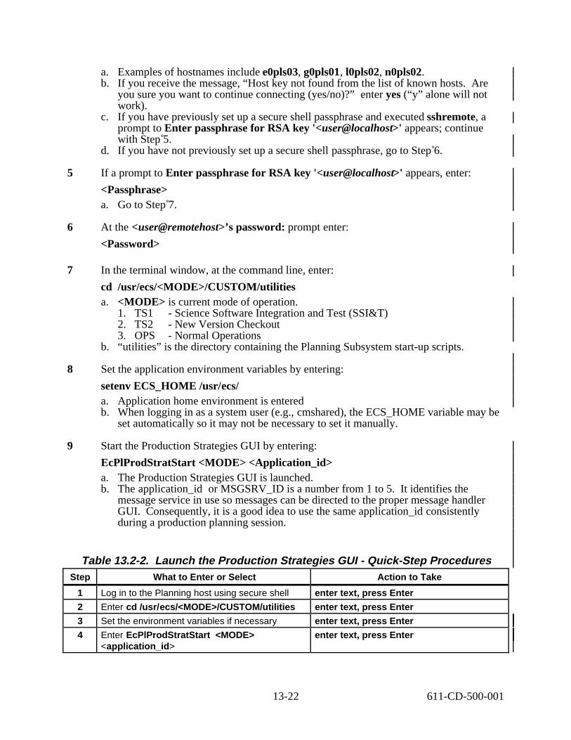
a. Examples of hostnames include e0pls03, g0pls01, l0pls02, n0pls02. b. If you receive the message, “Host key not found from the list of known hosts. Are
you sure you want to continue connecting (yes/no)?” enter yes (“y” alone will not work).
c. If you have previously set up a secure shell passphrase and executed sshremote, a prompt to Enter passphrase for RSA key '<user@localhost>' appears; continue with Step 5.
d. If you have not previously set up a secure shell passphrase, go to Step 6.
5 If a prompt to Enter passphrase for RSA key '<user@localhost>' appears, enter:
<Passphrase> a. Go to Step 7.
6 At the <user@remotehost>’s password: prompt enter:
<Password>
7 In the terminal window, at the command line, enter:
cd /usr/ecs/<MODE>/CUSTOM/utilities a. <MODE> is current mode of operation.
1. TS1 - Science Software Integration and Test (SSI&T) 2. TS2 - New Version Checkout 3. OPS - Normal Operations
b. “utilities” is the directory containing the Planning Subsystem start-up scripts.
8 Set the application environment variables by entering:
setenv ECS_HOME /usr/ecs/ a. Application home environment is entered b. When logging in as a system user (e.g., cmshared), the ECS_HOME variable may be
set automatically so it may not be necessary to set it manually.
9 Start the Production Strategies GUI by entering:
EcPlProdStratStart <MODE> <Application_id> a. The Production Strategies GUI is launched. b. The application_id or MSGSRV_ID is a number from 1 to 5. It identifies the
message service in use so messages can be directed to the proper message handler GUI. Consequently, it is a good idea to use the same application_id consistently during a production planning session.
Table 13.2-2. Launch the Production Strategies GUI - Quick-Step Procedures Step What to Enter or Select Action to Take
1 Log in to the Planning host using secure shell enter text, press Enter
2 Enter cd /usr/ecs/<MODE>/CUSTOM/utilities enter text, press Enter
3 Set the environment variables if necessary enter text, press Enter
4 Enter EcPlProdStratStart <MODE> <application_id>
enter text, press Enter
13-22 611-CD-500-001

13.2.2 Define or Modify a Production Strategy
The Production Planner uses the Production Strategies GUI to develop Production Strategies. Table 13.2-3 presents (in a condensed format) the steps required to define or modify a production strategy. If you are already familiar with the procedures, you may prefer to use this quick-step table. If you are new to the system, or have not performed this task recently, you should use the following detailed procedures.
1 Launch the Production Strategies GUI (refer to Section 13.2.1). a. The Production Strategies GUI is displayed.
2 If defining a new production strategy, select File → New from the pull-down menu. a. The fields of the Production Strategies GUI are reset.
3 If modifying an existing production strategy, first single-click the option button associated with the Production Strategies field, then highlight (in the option menu) the name of the production strategy to be modified. a. Data pertaining to the selected production strategy are displayed in the applicable
fields of the Production Strategies GUI. b. Alternatively, it is possible to select File → Open from the pull-down menu, select
the desired production strategy from the list on the Open window, and single-click on the Ok button to open the production strategy.
4 If changing the default priority for PR Type, single-click in the Default field below the PR Type button and enter the desired default value. a. The range for the default is from 1 to 10.
5 If changing the default priority for User Type, single-click in the Default field below the User Type button and enter the desired default value.
6 If changing the default priority for PGE Type, single-click in the Default field below the PGE Type button and enter the desired default value.
7 If defining or modifying a priority for a type of production request, first single-click on the PR Type button. a. The different types of production requests are displayed in the Type List field at the
bottom left of the GUI.
8 If defining a priority for a type of production request not currently listed in the PR Type Value-Priority list, single-click on that PR type in the Type List field. a. The PR type is highlighted. b. It is possible to highlight multiple PR types (by single-clicking on each one in turn) if
they are all going to be assigned the same priority.
9 If redefining or deleting a priority for a type of production request already listed in the PR Type Value-Priority list, single-click on that PR type in the Value-Priority list. a. The PR type is highlighted. b. It is possible to highlight multiple PR types (by single-clicking on each one in turn
while holding down either the Shift key or the Ctrl key) if the same action is going to be taken with respect to all of them.
13-23 611-CD-500-001

10 If defining or modifying (not deleting) a priority, click on the up/down arrow buttons to the right of the Priority field until the desired priority value is displayed in the Priority field. a. An alternative method of entering the priority is to enter the desired priority value in
the Priority field. b. The acceptable range for the priority is from 1 to 10.
11 Single-click on the appropriate button from the following selections: a. Add - to approve a priority for an additional PR type and display the selected PR type
and priority in the PR Type Value-Priority list at the left center of the GUI. b. Modify - to approve a revised priority for the selected PR type and display the PR
type and modified priority in the PR Type Value-Priority list. c. Delete - to delete the priority for the selected PR type and remove the PR type and
priority from the PR Type Value-Priority list.
12 Repeat Steps 7 through 11 as necessary until all PR Type priorities (as shown in the PR Type Value-Priority field) are correct.
NOTE: Although it is possible to enter values for different types of users, values assigned to the User Type category are not included in priority calculations. Calculation of priorities using User Type values may become functional when automated ondemand processing is implemented; i.e., in the Release 5B time frame. This affects Steps 13 through 18.
13 If defining or modifying a priority for a type of user, first single-click on the User Type button. a. The different types of users are displayed in the Type List field at the bottom left of
the GUI.
14 If defining a priority for a type of user not currently listed in the User Type Value-Priority list, single-click on that user type in the Type List field. a. The user type is highlighted. b. It is possible to highlight multiple user types (by single-clicking on each one in turn).
15 If redefining or deleting a priority for a user type already listed in the User Type Value-Priority list, single-click on that user type in the Value-Priority list. a. The user type is highlighted. b. It is possible to highlight multiple user types (by single-clicking on each one in turn
while holding down either the Shift key or the Ctrl key).
16 If defining or modifying (not deleting) a priority, click on the up/down arrow buttons to the right of the Priority field until the desired priority value is displayed in the Priority field. a. An alternative method of entering the priority is to enter the desired priority value in
the Priority field. b. The acceptable range for the priority is from 1 to 10.
17 Single-click on the appropriate button from the following selections: a. Add - to approve a priority for an additional user type and display the selected user
type and priority in the User Type Value-Priority list near the center of the GUI.
13-24 611-CD-500-001

b. Modify - to approve a revised priority for the selected user type and display the user type and modified priority in the User Type Value-Priority list.
c. Delete - to delete the priority for the selected user type and remove the user type and priority from the User Type Value-Priority list.
18 Repeat Steps 13 through 17 as necessary until all user type priorities (as shown in the User Type Value-Priority field) are correct.
19 If defining a priority for a type of PGE, first single-click on the PGE Type button. a. The different types of PGEs are displayed in the Type List field at the bottom left of
the GUI.
20 If defining a priority for a type of PGE not currently listed in the PGE Type Value-Priority list, single-click on that PGE type in the Type List field. a. The PGE type is highlighted. b. It is possible to highlight multiple PGE types (by single-clicking on each one in turn).
21 If redefining or deleting a priority for a PGE type already listed in the PGE Type Value-Priority list, single-click on that PGE type in the Value-Priority list. a. The PGE type is highlighted. b. It is possible to highlight multiple PGE types (by single-clicking on each one in turn
while holding down either the Shift key or the Ctrl key).
22 If defining or modifying (not deleting) a priority, click on the up/down arrow buttons to the right of the Priority field until the desired priority value is displayed in the Priority field. a. An alternative method of entering the priority is to enter the desired priority value in
the Priority field. b. The acceptable range for the priority is from 1 to 10.
23 Single-click on the appropriate button from the following selections: a. Add - to approve a priority for an additional PGE type and display the selected PGE
type and priority in the PGE Type Value-Priority list near the center of the GUI. b. Modify - to approve a revised priority for the selected PGE type and display the PGE
type and modified priority in the PGE Type Value-Priority list. c. Delete - to delete the priority for the selected PGE type and remove the PGE type and
priority from the PGE Type Value-Priority list.
24 Repeat Steps 19 through 23 as necessary until all PGE type priorities (as shown in the PGE Type Value-Priority field) are correct.
25 Single-click in the Weight field below the PR Type button and enter the desired weight. a. The acceptable range for weights is from 1 to 100. b. The Total Weight field displays updated totals of all weighting factors as they are
entered. c. When entering weights for the PR Type, User Type, PGE Type, and User Selected
factors, relative values can be entered without regard to whether the values in the four categories add up to 100. The Normalize button provides a means of eventually ensuring that the total of all four categories equals 100.
d. The assigned weight in each category is multiplied by the priority for each type. To maintain a high priority (low number, such as one), assign a low weight; to ensure a low priority, assign a relatively high weight.
13-25 611-CD-500-001

1
2
3
4
5
6
7
8
26 Single-click in the Weight field below the User Type button and enter the desired weight.
27 Single-click in the Weight field below the PGE Type button and enter the desired weight.
28 Single-click in the User Selected Weight field and enter the desired weight. a. The priority to which the user-selected weight is applied is the priority assigned using
the Production Request Editor when a production request is created.
29 Single-click on the Normalize button. a. The Planning Subsystem adjusts all weighting factors to produce a total weight of 100
(as displayed in the Total Weight field).
30 If it is necessary to change the priority of all jobs that produce data needed by other DAACs, single-click in the Inter DAAC Delta Priority field and enter the desired value. a. The range for Inter-DAAC Delta Priority is from 1 to 100. b. The lower the number, the higher the priority (1 is a high priority, 100 is a low
priority).
31 If it is necessary to change the priority of jobs that have been waiting in the Production Queue for more than a day, single-click in the Late Start Delta Priority field and enter the desired value. a. The range for the Late Start Delta Priority is from 1 to 100.
32 Select File → Save As from the pull-down menu. a. A Save As window similar to the File Selection window is displayed.
33 Enter the desired file name for the new production strategy in the Save As field.
34 Single-click on the Ok button to accept the file name in the Save As field. a. The Save As window is dismissed. b. The production strategy is saved with the specified file name.
35 To exit from the Production Strategies GUI select File → Exit from the pull-down menu.
Table 13.2-3. Define a Production Strategy - Quick-Step Procedures (1 of 2) Step What to Enter or Select Action to Take
Launch Production Strategies GUI Use procedure in Section 13.2.1
Select File → New single-click
Enter PR Type <default priority> if applicable enter text
Enter User Type <default priority> if applicable enter text
Enter PGE Type <default priority> if applicable enter text
Select PR Type button. single-click
Select <PR type> from the Type List field single-click
Enter <priority> in the Priority field enter text or single-click as necessary
13-26 611-CD-500-001

Table 13.2-3. Define a Production Strategy - Quick-Step Procedures (2 of 2) Step What to Enter or Select Action to Take
9 Select Add single-click
10 Repeat Steps 7 through 9 for additional PR types if applicable
11 Select User Type button. single-click
12 Select <user type> from the Type List field single-click
13 Enter <priority> in the Priority field enter text or single-click as necessary
14 Select Add single-click
15 Repeat Steps 12 through 14 for additional user types if applicable
16 Select PGE Type button. single-click
17 Select <PGE type> from the Type List field single-click
18 Enter <priority> in the Priority field enter text or single-click as necessary
19 Select Add single-click
20 Repeat Steps 17 through 19 for additional PGE types if applicable
21 Enter PR Type <weight> enter text
22 Enter User Type <weight> enter text
23 Enter PGE Type <weight> enter text
24 Enter User Selected <weight> enter text
25 Select the Normalize button single-click
26 Enter <Inter DAAC Delta Priority> enter text
27 Enter <Late Start Delta Priority> enter text
28 Select File → Save As single-click
29 Enter production strategy <file name> in the Save As field
enter text
30 Select Ok single-click
31 Select File → Exit single-click
13.2.3 Launch the Planning Workbench and Planning Timeline GUIs
The Planning Workbench and Planning Timeline GUIs are invoked from a UNIX command line prompt. Table 13.2-4 presents (in a condensed format) the steps required to launch the Planning Workbench and Planning Timeline GUIs. If you are already familiar with the procedures, you may prefer to use the quick-step table. If you are new to the system, or have not performed this task recently, you should use the following detailed procedures.
1 At the UNIX command line prompt enter:
xhost <hostname> a. <hostname> refers to the host on which GUI is to be launched during the current
operating session. Multiple hostnames can be specified on the same line. b. The use of xhost + is discouraged because of a potential security problem.
13-27 611-CD-500-001

2 In the Terminal window, at the command line prompt, enter:
setenv DISPLAY <clientname>:0.0 a. Use either the X terminal/workstation IP address or the machine-name for the
clientname. b. When using secure shell, the DISPLAY variable is set just once, before logging in to
remote hosts. If it were to be reset after logging in to a remote host, the security features would be compromised.
3 Open another UNIX (terminal) window.
4 In the terminal window, at the command line prompt, start the log-in to the Planning/Management Workstation by entering:
/tools/bin/ssh <hostname> a. Examples of hostnames include e0pls03, g0pls01, l0pls02, n0pls02. b. If you receive the message, “Host key not found from the list of known hosts. Are
you sure you want to continue connecting (yes/no)?” enter yes (“y” alone will not work).
c. If you have previously set up a secure shell passphrase and executed sshremote, a prompt to Enter passphrase for RSA key '<user@localhost>' appears; continue with Step 5.
d. If you have not previously set up a secure shell passphrase, go to Step 6.
5 If a prompt to Enter passphrase for RSA key '<user@localhost>' appears, enter:
<Passphrase> a. Go to Step 7.
6 At the <user@remotehost>’s password: prompt enter:
<Password>
7 In the terminal window, at the command line, enter:
cd /usr/ecs/<MODE>/CUSTOM/utilities a. <MODE> is current mode of operation.
1. TS1 - Science Software Integration and Test (SSI&T) 2. TS2 - New Version Checkout 3. OPS - Normal Operations
b. “utilities” is the directory containing the Planning Subsystem start-up scripts.
8 Set the application environment variables by entering:
setenv ECS_HOME /usr/ecs/ a. Application home environment is entered b. When logging in as a system user (e.g., cmshared), the ECS_HOME variable may be
set automatically so it may not be necessary to set it manually.
13-28 611-CD-500-001

9 Start the Planning Workbench-related applications by entering:
EcPlAllStart <MODE> <Application_id> a. The System Name Server, Resource Model, Message Handler, Planning Workbench
GUI and Planning Timeline GUI are launched. b. The application_id or MSGSRV_ID is a number from 1 to 5. It identifies the
message service in use so messages can be directed to the proper message handler GUI. Consequently, it is a good idea to use the same application_id consistently during a production planning session.
10 Adjust the window size of the Planning Timeline (if necessary) to allow access to other items in the workspace.
Table 13.2-4. Launch the Planning Workbench - Quick-Step Procedures Step What to Enter or Select Action to Take
1 Log in to the Planning host using secure shell enter text, press Enter
2 Enter cd /usr/ecs/<MODE>/CUSTOM/utilities enter text, press Enter
3 Set the environment variables if necessary enter text, press Enter
4 Enter EcPlAllStart <MODE> <application_id> enter text, press Enter
13.2.4 Create New Production Plan
The new Production Plan process begins when the Production Planner starts the Planning Workbench. The Production Planner will perform the high level functions, such as creating a plan, deciding when to activate, cancel, and replan.
The Production Planner will bring the plan back on track due to late data arrivals, QA issues, equipment failures and other events that can cause significant delays in the processing of the associated products.
Table 13.2-5 presents (in a condensed format) the steps required to create a new Production Plan. If you are already familiar with the procedures, you may prefer to use this quick-step table. If you are new to the system, or have not performed this task recently, you should use the following detailed procedures:
1 Launch the Planning Workbench (refer to Section 13.2.3). a. The Planning Workbench and Planning Timeline GUIs are displayed.
2 Select File → New on the Planning Workbench GUI. a. The New Plan window is displayed.
3 Enter the plan name in the Plan Name field, then single-click on the Ok button. a. Name is displayed in Plan Name field. b. Status is Candidate.
4 If applicable, single-click on the option button associated with the Strategy field, then select the desired production strategy from the option menu.
5 Single-click inside the Comment field and enter any relevant comments.
13-29 611-CD-500-001

a. The “sash” button (the line separating the area between the comment field and the scheduling PR area with a square box on the right hand side) may be used to expand or contract the text area.
6 Select a Production Request to be scheduled by single-clicking on the request line and single-clicking on schedule/unschedule up and down arrows to move the Production Request from the Unscheduled panel to the Scheduled panel or vice versa. a. Production Request will appear in the appropriate panel. b. Operator can single-click on multiple Production Requests to add them all at the same
time. c. If the PR depends upon another PR that is not scheduled, then the message
“Production Request “xxx” must be selected before DPR “yyy” of Production Request “zzz” can be scheduled. If all DPRs associated with a PR have been run, the PR cannot be rescheduled.
d. If processing of the currently active plan is to be continued when the new plan is activated, include the PR(s) for the currently active plan in the new plan.
e. In the Scheduled list, items with the prefix “GE_” are resource reservations (also called “ground events”).
f. All ground events are automatically scheduled with any plan; therefore, the ground events are normally displayed in the Scheduled list.
g. Whenever a plan is activated, the ground events are activated as well as the DPRs associated with the specified PRs.
h. If a ground event appears in the Unscheduled list, the ground event has lost allocations.
7 Select File → Save As from the pull-down menu. a. The Save Plan window is displayed.
8 Enter the plan name in the Plan Name field, then single-click on the Ok button. a. The Save Plan window is dismissed. b. The production plan is saved with the specified file name. c. Status is Candidate.
9 If appropriate, single-click on the Activate button to activate the new Plan. a. The Rollover Time area is automatically filled when a new plan is activated. b. Clicking on the Activate button activates a plan and the Data Processing Requests
(DPRs) associated with the planned PRs are transferred to the Data Processing Subsystem and loaded into the AutoSys production queuing system.
c. Once its data dependencies have been satisfied, each DPR is “released” to be run as processing resources become available.
d. Clicking on the Activate button causes the current active plan to get "replanned over" by the selected plan.
10 If it is desired to a baseline a plan, single-click on the Baseline button then single-click on Yes. a. “The current plan is <planname>. Do you wish to baseline it?” window appears. b. Clicking on the Baseline button records the plan and the time of baselining. c. A baseline plan can be used as a point of comparison with which to compare future
plans and results.
11 Select File → Exit to quit the Planning Workbench.
13-30 611-CD-500-001

12 After quitting the Planning Workbench GUI single-click in the UNIX window used to start the Planning Workbench GUI. a. The Message Handler, System Name Server, and Resource Model should be shut
down to eliminate unneeded processes and allow other operators to gain access to the Planning Workbench if necessary.
13 Shut down Planning Workbench-related applications by entering:
EcPlSlayAll <MODE> <Application_id> a. The following Planning Workbench-related applications shut down:
1. Planning Workbench (if it has not already been shut down). 2. Planning Timeline (if it has not already been shut down). 3. Message Handler. 4. System Name Server. 5. Resource Model.
14 Obtain a list of active processes in the specified mode by entering:
ps -ef | grep <MODE> a. A list of active processes in the specified mode is displayed. b. If an error message is received when ps -ef | grep <MODE> is entered, enter:
ps -auxwww | grep <MODE>
15 Examine the list of processes running in the specified mode to determine whether the Message Handler, System Name Server, and Resource Model processes have actually been shut down. a. None of the following processes should be active:
1. EcPlWb 2. EcPlTl 3. EcPlMsh 4. EcPlSns 5. EcPlRm
16 If any of the specified processes [especially the Message Handler, System Name Server, and/or Resource Model process(es)] is/are still active, terminate the active process(es) by entering:
kill -15 <PROCESS_ID1> <PROCESS_ID2> <…> <PROCESS_IDx>
17 Repeat Steps 14 through 16 as necessary.
13-31 611-CD-500-001

1
2
3
4
5
6
Table 13.2-5. Create New Production Plan - Quick-Step Procedures Step What to Enter or Select Action to Take
Launch Planning Workbench Use procedure in Section 13.2.3
Select File → New single-click
Enter <Plan Name> enter text
Select Ok single-click
Select <Strategy> single-click
Select <Production Request(s)> to schedule/unschedule
single-click
7 Select Schedule button or Unschedule button as applicable
single-click
8 Schedule/Unschedule Production Requests single-click
9 Select File → Save As single-click
10 Enter <Plan Name> enter text
11 Select Ok single-click
12 Select Activate if applicable single-click if applicable
13 Select File → Exit single-click
14 Enter EcPlSlayAll <MODE> <Application_id>
enter text, press Enter
15 Enter ps -ef | grep <MODE> enter text, press Enter
16 Enter kill -15 <PROCESS_ID1> <PROCESS_ID2> <…> <PROCESS_IDx> to terminate active process(es)
enter text, press Enter if applicable
13.2.5 Review Plan Timeline
Table 13.2-6 presents (in a condensed format) the steps required to review planning timelines. If you are already familiar with the procedures, you may prefer to use this quick-step table. If you are new to the system, or have not performed this task recently, you should use the following detailed procedures.
1 Launch the Planning Workbench and Timeline GUIs (refer to Section 13.2.3). a. The Planning Timeline GUI is displayed. b. If you have previously saved a configuration file, you may load it as follows:
1. Select File → Load Configuration from menu (change directory in GUI box, if necessary).
c. Otherwise continue with Step 2.
2 Select File → Open Plan from the pull-down menu bar. a. List of plans appears.
13-32 611-CD-500-001

3 Select the plan to be reviewed. a. The timeline for the specific plan is displayed. b. Name is displayed in the Title bar.
4 Single-click on the Ok button.
5 Observe the production plan information displayed on the timeline GUI.
6 If a different time scale (start and end dates and times) is desired, perform Steps 7 through 9; otherwise, go to Step 10.
7 Select Time → Change Plan Window. a. plan window edit window appears with default times.
8 Enter Plan Win Start date and time. a. DD MMM YYYY and hh:mm:ss are displayed.
9 Enter Plan Win End date and time then single-click on Ok. a. DD MMM YYYY and hh:mm:ss are displayed.
10 If a different time span is desired, single-click on the Show pushbutton and select one of 12 time increments between 5 min to 168 hrs for the timeline scale. a. The entry “OTHER” has no purpose at this time.
11 If no resources are displayed on the GUI or if different resources should be displayed, perform Steps 12 through 15; otherwise, go to Step 16.
12 Select Display → Change resources. a. Resource edit window with lists of Available Resources and Viewed Resources is
displayed.
13 Single-click resource(s) in desired list then single-click Add or Del. a. Add move the resource(s) from the Available list to the Viewed list. b. Del removes items from the Viewed List.
14 To change to order in which resources are displayed on the timeline, single-click on an item in the Viewed Resources list then single-click on the up or down arrow as appropriate. a. Selected resource moves up or down in order on the list.
15 Single-click on the Ok button.
16 If different color coding of the timeline is desired, perform Steps 17 through 19; otherwise, go to Step 20.
17 Select Display → Change colors. a. Color grid appears with a list of Production Requests.
18 Single-click on the Production Request name then single-click desired color for that Production Request. a. Color is changed for the selected Production Request.
13-33 611-CD-500-001

b. New color appears on the horizontal bar between color and Production Request selections.
19 Single-click on the Ok button.
20 Observe the production plan information displayed on the timeline GUI.
21 If desired, save your current configuration as a file. If you have not previously saved your current configuration and wish to do so: a. Select File → Save Configuration from menu.
22 To exit the Planning Master Timeline, select File → Exit from the pull-down menu.
Table 13.2-6. Review Plan Timeline - Quick-Step Procedures (1 of 2) Step What to Enter or Select Action to Take
1 Launch Planning Workbench and Timeline Use procedure in Section 13.2.3
2 Load configuration file (File → Load Configuration) (optional)
single-click
3 Select File → Open Plan single-click
4 Select <Plan> single-click
5 Observe the production plan information read text
6 Select Time → Change Plan window single-click
7 Enter plan window <start date and time> enter text
8 Enter plan window <end date and time> enter text
9 Select Ok single-click
10 Select <time span> single-click
11 Select Display → Change resources single-click
12 Select <resources> single-click
13 Select Add single-click
14 Select <viewed resource> to be reordered single-click
15 Reorder viewed resources using up/down arrows single-click
16 Select Ok single-click
17 Select Display → Change colors single-click
18 Select <Production Request> single-click
19 Select <color> for Production Request single-click
20 Select Ok single-click
21 Observe the production plan information read text
22 Select File → Save Configuration single-click
23 Enter <file name> enter text
24 Select Ok single-click
13-34 611-CD-500-001

13.3 Submitting or Withdrawing a Subscription Using the Subscription Editor
The Subscription Editor is a character-based user interface that may be used to either submit or withdraw subscriptions for notification of data arrival (i.e., insertion of data into the archive) or other subscribable system events.
a. Subscriptions may be submitted on behalf of a general user or on behalf of the Planning Subsystem (i.e., the PLS Subscription Manager).
b. An advantage of the character-based Subscription Editor over the Subscription GUI is the ability to submit subscriptions without being a registered user of ECS.
Submitting or withdrawing a subscription using the Subscription Editor starts with the assumption that the applicable servers are running and the Production Planner has logged in to the ECS system.
Table 13.3-1. Subscription - Activity Checklist Order Role Task Section Complete?
1 Production Planner Submit or Withdraw a Subscription Using the Subscription Editor
(P) 13.3.1
13.3.1 Submit or Withdraw a Subscription Using the Subscription Editor
Table 13.3-2 presents (in a condensed format) the steps required to submit or withdraw a subscription using the subscription editor. If you are already familiar with the procedures, you may prefer to use this quick-step table. If you are new to the system, or have not performed this task recently, you should use the following detailed procedures.
1 At the UNIX command line prompt enter:
xhost <hostname> a. <hostname> refers to the host on which GUI is to be launched during the current
operating session. Multiple hostnames can be specified on the same line. b. The use of xhost + is discouraged because of a potential security problem.
2 In the Terminal window, at the command line prompt, enter:
setenv DISPLAY <clientname>:0.0 a. Use either the X terminal/workstation IP address or the machine-name for the
clientname. b. When using secure shell, the DISPLAY variable is set just once, before logging in to
remote hosts. If it were to be reset after logging in to a remote host, the security features would be compromised.
3 Open another UNIX (terminal) window.
4 In the terminal window, at the command line prompt, start the log-in to the Planning/Management Workstation by entering:
/tools/bin/ssh hostname a. Examples of hostnames include e0pls03, g0pls01, l0pls02, n0pls02.
13-35 611-CD-500-001

b. If you receive the message, “Host key not found from the list of known hosts. Are you sure you want to continue connecting (yes/no)?” enter yes (“y” alone will not work).
c. If you have previously set up a secure shell passphrase and executed sshremote, a prompt to Enter passphrase for RSA key '<user@localhost>' appears; continue with Step 5.
d. If you have not previously set up a secure shell passphrase, go to Step 6.
5 If a prompt to Enter passphrase for RSA key '<user@localhost>' appears, enter:
<Passphrase> a. Go to Step 7.
6 At the <user@remotehost>’s password: prompt enter:
<Password>
7 In the terminal window, at the command line, enter:
cd /usr/ecs/<MODE>/CUSTOM/utilities a. <MODE> is current mode of operation.
1. TS1 - Science Software Integration and Test (SSI&T) 2. TS2 - New Version Checkout 3. OPS - Normal Operations
b. “utilities” is the directory containing the Planning Subsystem start-up scripts.
8 Set the application environment variables by entering:
setenv ECS_HOME /usr/ecs/ a. Application home environment is entered b. When logging in as a system user (e.g., cmshared), the ECS_HOME variable may be
set automatically so it may not be necessary to set it manually.
9 Start the Subscription Editor by entering:
EcPlSubsEditStart <MODE> <Application_id> a. The following message is displayed:
This program may be used to submit subscriptions for notification of data arrivals, on behalf of a general user, or on behalf of the PDPS production system (ie. the PLS Subscription Manager)
Would you like to view the complete list of ESDTs known to PDPS? (y/n):
10 Enter either y or n (as appropriate). a. Either lower-case or upper-case letters may be entered. b. If y was entered, a message similar to the following message is displayed:
AP#0 Subscription Flag: 1 DAP#0 Subscription Flag: 1 FAILPGE#0 Subscription Flag: 1 MOD00#0 Subscription Flag: 0 MOD01#0 Subscription Flag: 0
13-36 611-CD-500-001

MOD021KM#0 Subscription Flag: 0MOD02LUT#0 Subscription Flag: 0MOD03#0 Subscription Flag: 0MOD03LUT#0 Subscription Flag: 0MOD29#0 Subscription Flag: 0PGEEXE#0 Subscription Flag: 1PH#0 Subscription Flag: 1SSAPC#0 Subscription Flag: 1Is recipient PLS Subscription Manager (Y/N):
c. If n was entered, the following message is displayed:
Is recipient PLS Subscription Manager (Y/N):
11 Enter either y or n (as appropriate). a. If y was entered, the following message is displayed:
Enter ESDT data type name (as appears in the PDPS database): b. If y was entered, skip Steps 12 and 13, and go to Step 14. c. If n was entered, the following message is displayed:
Enter user id:
12 In response to the “Enter user id” message enter: <UserID> a. The following message is displayed:
Enter email address (for subscription notification):
13 In response to the “Enter email address…” message enter:
<e-mail address> a. The following message is displayed:
Enter ESDT data type name (as appears in the PDPS database):
14 Enter <ESDT> a. For example: FAILPGE#0 Subscription Flag: 1 b. The following message is displayed:
Override the provider [SYSTEM] defined for this ESDT (Y/N)
15 Enter either Y or N (as appropriate). a. The following message is displayed:
Submit(S)/Withdraw(W) :
16 Enter either S or W (as appropriate). a. If S was entered, the following message is displayed:
Specify the Internal Service Name Enter 'd' for default Insert Event service
b. If W was entered, the following message is displayed:
13-37 611-CD-500-001
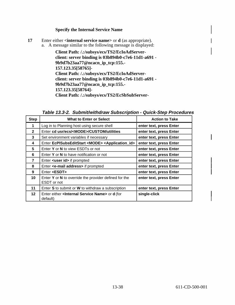
1
2
3
4
5
6
7
8
9
10
Specify the Internal Service Name
17 Enter either <internal service name> or d (as appropriate). a. A message similar to the following message is displayed:
Client Path: /.:/subsys/ecs/TS2/EcIoAdServerclient: server binding is 03b894b0-c7e6-11d1-a6919b9d7b23aa77@ncacn_ip_tcp:155.157.123.35[58765]Client Path: /.:/subsys/ecs/TS2/EcIoAdServerclient: server binding is 03b894b0-c7e6-11d1-a6919b9d7b23aa77@ncacn_ip_tcp:155.157.123.35[58764]Client Path: /.:/subsys/ecs/TS2/EcSbSubServer
Table 13.3-2. Submit/withdraw Subscription - Quick-Step Procedures Step What to Enter or Select Action to Take
Log in to Planning host using secure shell enter text, press Enter
Enter cd usr/ecs/<MODE>/CUSTOM/utilities enter text, press Enter
Set environment variables if necessary enter text, press Enter
Enter EcPlSubsEditStart <MODE> <Application_id> enter text, press Enter
Enter Y or N to view ESDTs or not enter text, press Enter
Enter Y or N to have notification or not enter text, press Enter
Enter <user id> if prompted enter text, press Enter
Enter <e-mail address> if prompted enter text, press Enter
Enter <ESDT> enter text, press Enter
Enter Y or N to override the provider defined for the ESDT or not
enter text, press Enter
11 Enter S to submit or W to withdraw a subscription enter text, press Enter
12 Enter either <Internal Service Name> or d (for default)
single-click
13-38 611-CD-500-001

14. Production Processing
The Data Processing Subsystem provides a batch processing environment to support the generation of data products. It manages, queues, and executes Data Processing Requests (DPR) on the processing resources at a DAAC. A DPR can be defined as one science processing job. Each DPR encapsulates all of the information needed to execute the processing job. DPRs are submitted from the Planning Subsystem and their processing is triggered by the availability of their input data.
DPRs use Product Generation Executives (PGEs) to perform processing. PGEs result from the integration and test of delivered science algorithms and also user-specific methods in the Data Processing Subsystem. They are encapsulated in the ECS environment through the SDP Toolkit. The Data Processing Subsystem provides the operational interfaces needed to monitor the execution of science software PGEs.
Each procedure outlined will have an Activity Checklist table that will provide an overview of the task to be completed. The outline of the Activity Checklist is as follows: Column one - Order shows the order in which tasks should be accomplished.
Column two - Role lists the Role/Manager/Operator responsible for performing the task.
Column three - Task provides a brief explanation of the task.
Column four - Section provides the Procedure (P) section number or Instruction (I) section number where details for performing the task can be found.
Column five - Complete? is used as a checklist to keep track of which task steps have been completed.
The following Activity Checklist, Table 14.1-1, provides an overview of production processing.
Table 14.1-1. Production Planning - Activity Checklist (1 of 2) Order Role Task Section Complete?
1 Production Monitor Launch the AutoSys GUI Control Panel (P) 14.1.1
2 Production Monitor Configure AutoSys/AutoXpert Runtime Options
(P) 14.1.2
3 Production Monitor Configure Hardware Groups (P) 14.1.3
4 Production Monitor Review Hardware Status (P) 14.2.1
5 Production Monitor Select Hardware Status View Options (P) 14.2.2
6 Production Monitor Review DPR Dependencies (P) 14.3
7 Production Monitor Review DPR Production Timeline (P) 14.4
8 Production Monitor Review Alarms (P) 14.5.1
9 Production Monitor Select Alarms for Alarm Manager Display
(P) 14.5.2
14-1 611-CD-500-001

Table 14.1-1. Production Planning - Activity Checklist (2 of 2) Order Role Task Section Complete?
10 Production Monitor Specify Job Selection Criteria (P) 14.6.1
11 Production Monitor Review Job Activities Using the AutoSys Job Activity Console
(P) 14.6.2
12 Production Monitor Determine the Ownership of an AutoSys Job
(P) 14.7.1
13 Production Monitor Modify Job Status (P) 14.7.2
14 Production Monitor Cancel a Sent Event (P) 14.7.3
15 Production Monitor Perform Job Management Functions (P) 14.7.4
16 Production Monitor Review Activity Log (P) 14.8.1
17 Production Monitor Review Job Dependency Log (P) 14.8.2
18 Production Monitor Define Monitors/Browsers (P) 14.9.1
19 Production Monitor Run Monitor/Browser from the Monitor/Browser GUI
(P) 14.9.2
20 Production Monitor Run Monitor/Browser from the Command Shell
(P) 14.9.3
21 Production Monitor Change AutoSys Event Processor Database Maintenance Time
(P) 14.10.1
22 Production Monitor Modify the Maximum Number of Jobs in AutoSys
(P) 14.10.2
14.1 Launch the AutoSys GUI Control Panel and Configure AutoSys Runtime Options
The process of configuring AutoSys begins when the Production Monitor starts the AutoSys graphical user interface (GUI) Control Panel and changes runtime options or uses the vi editor to modify configuration files.
The procedures in this section concern launching the AutoSys GUIs, configuring AutoSys runtime options, and configuring AutoSys hardware groups.
14.1.1 Launching the AutoSys GUI Control Panel
The AutoSys GUI Control Panel is invoked from a UNIX command line prompt. Table 14.1-2 presents (in a condensed format) the steps required to launch the AutoSys GUI Control Panel. If you are already familiar with the procedures, you may prefer to use the quick-step table. If you are new to the system, or have not performed this task recently, you should use the following detailed procedures:
1 At the UNIX command line prompt enter:
xhost <hostname> a. <hostname> refers to the host on which GUI is to be launched during the current
operating session. Multiple hostnames can be specified on the same line. b. The use of xhost + is discouraged because of a potential security problem.
14-2 611-CD-500-001

2 In the Terminal window, at the command line prompt, enter:
setenv DISPLAY <clientname>:0.0 a. Use either the X terminal/workstation IP address or the machine-name for the
clientname. b. When using secure shell, the DISPLAY variable is set just once, before logging in to
remote hosts. If it were to be reset after logging in to a remote host, the security features would be compromised.
3 Open another UNIX (terminal) window.
4 In the terminal window, at the command line prompt, start the log-in to the Queuing Server by entering:
/tools/bin/ssh <hostname> a. Examples of hostnames include e0sps04, g0sps06, l0sps03, n0sps08. b. If you receive the message, “Host key not found from the list of known hosts. Are
you sure you want to continue connecting (yes/no)?” enter yes (“y” alone will not work).
c. If you have previously set up a secure shell passphrase and executed sshremote, a prompt to Enter passphrase for RSA key '<user@localhost>' appears; continue with Step 5.
d. If you have not previously set up a secure shell passphrase, go to Step 6.
5 If a prompt to Enter passphrase for RSA key '<user@localhost>' appears, enter:
<Passphrase> a. Go to Step 7.
6 At the <user@remotehost>’s password: prompt enter:
<Password>
7 In the terminal window, at the command line, enter:
cd /usr/ecs/ <MODE>/COTS/autotree/autouser a. <MODE> is current mode of operation.
1. TS1 - Science Software Integration and Test (SSI&T) 2. TS2 - New Version Checkout 3. OPS - Normal Operations
b. “autouser” is the directory containing the AutoSys configuration files. c. The path may vary with the specific site installation; e.g., the autotree directory may
be identified as autotreeb at some sites.
14-3 611-CD-500-001

8 Set the application environment variables by entering:
setenv ECS_HOME /usr/ecs/
source <AUTOSERV_INSTANCE>.autosys.csh.<hostname> a. Application home environment is entered. b. When logging in as a system user (e.g., cmshared), the ECS_HOME variable may be
set automatically so it may not be necessary to set it manually. c. <AUTOSERV_INSTANCE> (also called an AUTOSYS instance) is installed as
part of the Data Processing Subsystem and is identified by three capital letters. 1. AUTOSERV instances at the DAACs are typically identified as FMR. 2. Configuration files in the autouser directory identify the available AUTOSERV
instances. For example, config.FMR is the configuration file for AUTOSERV instance FMR.
9 Launch the AutoSys GUI Control Panel by entering:
cd /usr/ecs/ <MODE>/CUSTOM/utilities
EcDpPrAutosysStart <MODE> <AUTOSERV_INSTANCE> a. The AutoSys GUI Control Panel is displayed.
Table 14.1-2. Launch AutoSys GUI Control Panel - Quick-Step Procedures Step What to Enter or Select Action to Take
1 Log in to the ECS System using secure shell enter text, press Enter
2 Set the environment variables enter text, press Enter
3 Enter cd /usr/ecs/ <MODE>/COTS/autotree/autouser enter text, press Enter
4 Enter source <AUTOSERV_INSTANCE>.autosys.csh.<hostname>
enter text, press Enter
5 Enter cd /usr/ecs/<MODE>/CUSTOM/utilities enter text, press Enter
6 Enter EcDpPrAutosysStart <MODE> <AUTOSERV_INSTANCE>
enter text, press Enter
14.1.2 Configuring AutoSys/AutoXpert Runtime Options
The following AutoSys/AutoXpert Runtime Options may be defined by the Production Monitor operator:
a. Refresh Interval - The Refresh Interval is how often the GUI View Region display is updated.
b. Ping Interval - The Ping Interval is defined by how often the connectivity is evaluated.
c. Hang Time - The Hang Time is the length of time jobs continue to be displayed within a machine after they have completed running.
d. Inches/Hour- Inches/Hour specifies how much information is displayed on the screen. All values are initially set to default values by the AutoSys system.
Table 14.1-3 lists the runtime options available for HostScape, TimeScape, and JobScape. Not all options are available for all GUIs.
14-4 611-CD-500-001

HostScape displays jobs on a machine-by-machine basis, indicating which AutoSys server/client machines are up and active, and which jobs are running or have recently run on each machine. This interface is used to monitor hardware status in real-time.
TimeScape presents a Gantt-like view of a job processing from a temporal (or time-related) point-of-view. This interface depicts both “command jobs” and “box jobs.” It also depicts the nesting of jobs within boxes and the duration of time it will take for jobs to complete. This interface is used to monitor job flow in real-time.
JobScape presents a Pert-like view of job processing from a logical (or job dependency) point of view. This interface depicts both “command jobs” and “box jobs.” It also depicts the nesting of jobs within boxes and the dependencies between jobs. This interface can be used to monitor job flow in real-time.
Table 14.1-3. Runtime Options Table Interface Refresh Interval Hangtime PING Inches/Hour
HostScape X X X
TimeScape X X
JobScape X
Table 14.1-4 presents (in a condensed format) the steps required to configure AutoSys runtime options. If you are already familiar with the procedures, you may prefer to use the quick-step table. If you are new to the system, or have not performed this task recently, you should use the following detailed procedures (perform only those steps applicable to the interface, as defined in Table 14.1-3.):
1 Launch the AutoSys GUI Control Panel (refer to Section 14.1.1). a. The AutoSys GUI Control Panel is displayed.
2 Single-click on either HostScape, TimeScape, or JobScape button on the AutoSys GUI Control Panel. a. The desired GUI dialog box is displayed.
3 Display the Runtime Options dialog box by executing the following menu path:
Options → Edit Runtime Options a. The Runtime Options dialog box is displayed.
4 Single-click Refresh Interval (Seconds) and enter a value between 1 and 99999. a. Value is entered. b. Default value is 30 c. Reloading Job Data window reappears every ## seconds. d. If Freeze Frame feature is enabled, changes will not take place until it is disabled.
14-5 611-CD-500-001

5 Single-click Ping Interval (Seconds) (if applicable) and enter a value between 1 and 99999. a. Value is entered. b. Default value is 300 c. 99999 means no ping commands are issued. d. If Freeze Frame feature is enabled, changes will not take place until it is disabled.
6 Single-click Hang Time (Minutes) (if applicable) and enter a value between 1 and 99999. a. Value is entered. b. Default value is 1 c. If Freeze Frame feature is enabled, changes will not take place until it is disabled.
7 Single-click Inches/Hr (inches) (if applicable) and enter a value between 1 and ###. a. Value is entered. b. Default value is 2 c. If Freeze Frame feature is enabled, changes will not take place until is disabled.
8 Single-click Apply. a. The Runtime Options are set.
9 Single-click OK. a. The dialog box closes.
Table 14.1-4. Configure AutoSys Runtime Options - Quick-Step Procedures Step What to Enter or Select Action to Take
1 Launch the AutoSys GUI Control Panel Use procedure in Section 14.1.1
2 Select either HostScape, TimeScape, or JobScape
single-click
3 Select Options → Edit Runtime Options single-click
4 Select Refresh Interval (Seconds) single-click
5 Enter a value between 1 and 99999 enter number
6 Select Ping Interval (Seconds) (if applicable) single-click
7 Enter a value between 1 and 99999 (if applicable) enter number
8 Select Hang Time (Minutes) (if applicable) single-click
9 Enter a value between 1 and 99999 (if applicable) enter number
10 Select Inches/Hr (inches) (if applicable) single-click
11 Enter value (if applicable) enter number
12 Select Apply single-click
13 Select OK single-click
14.1.3 Configure Hardware Groups
This section explains how to configure AutoSys hardware groups. The default group is “All Machines.” If the Production Monitor needs to monitor specific sets of machines, groups may be defined.
14-6 611-CD-500-001

Table 14.1-5 presents (in a condensed format) the steps required to configure AutoSys hardware groups. If you are already familiar with the procedures, you may prefer to use the quick-step table. If you are new to the system, or have not performed this task recently, you should use the following detailed procedures:
1 At the UNIX command line prompt enter:
cd /usr/ecs/ <MODE>/COTS/autotree/autouser
2 Edit the file called xpert.groups.<AUTOSERV_INSTANCE> using an appropriate text editor (e.g., vi).
3 Enter:
groupname: <groupname>
4 Enter:
<machine name>
Groupname: Modisd0pls01d0sps03Groupname: SSI&Td0ais01d0spg02
Figure 14.1-1. AutoSys Hardware Group File Example
(Repeat Step 4 for each item in the group.)
Repeat Steps 3 and 4 for additional groups.
5 Save the file.
6 Launch the AutoSys GUI Control Panel (refer to Section 14.1.1). a. The AutoSys GUI Control Panel is displayed.
7 Single-click HostScape. a. The HostScape GUI page is presented.
14-7 611-CD-500-001

8 Display the Machine Group Selection dialog box by executing the following menu path:
View → Select Machine Group a. The Machine Group Selection dialog box is presented.
9 Select <machine group>. a. The machine group is highlighted.
10 Single-click Apply button. a. The selected machine group is applied.
11 Single-click OK button. a. The Machine Group Selection dialog box is closed b. The HostScape display should now show the selected group of machines.
Table 14.1-5. Configure AutoSys Hardware Groups - Quick-Step Procedures Step What to Enter or Select Action to Take
1 cd /usr/ecs/ <MODE>/COTS/autotree/autouser enter text, press Enter
2 Edit file xpert.groups.<AUTOSERV_INSTANCE>
enter text, press Enter
3 Enter groupname: <groupname> enter text, press Enter
4 Enter <machine name > enter text, press Enter
5 Repeat Steps 3 and 4 as necessary for additional groups/machines
enter text, press Enter
6 Save the file enter text, press Enter
7 Launch the AutoSys GUI Control Panel Use procedure in Section 14.1.1
8 Select HostScape single-click
9 Execute menu path: View → Select Machine Group
single-click
10 Select <machine group> to be presented single-click
11 Select Apply single-click
12 Select OK single-click
14.2 Review Hardware Status
The process of reviewing hardware status begins with the Production Monitor launching AutoSys HostScape. Hardware status is reviewed using the AutoSys HostScape GUI, which allows real-time monitoring.
14.2.1 Review Hardware Status
Table 14.2-1 presents (in a condensed format) the steps required to review hardware status using AutoSys HostScape. If you are already familiar with the procedures, you may prefer to use the quick-step table. If you are new to the system, or have not performed this task recently, you should use the following detailed procedures:
14-8 611-CD-500-001

1 Launch the AutoSys GUI Control Panel (refer to Section 14.1.1). a. The AutoSys GUI Control Panel is displayed.
2 Single-click on the HostScape button on the AutoSys GUI Control Panel. a. The HostScape GUI page is presented. b. View presented is Normal View.
3 Review the Control Region (left side of display) to identify color code for status of machines. This code is displayed on the machine box border in the View Region. a. MACHINE UP (active) is Green. b. MACHINE DOWN (inactive and cannot be reached) is Red. c. Machine Inactive is Black. (Not shown in Control Region)
4 Review machine type in View Region. a. The machine name is displayed. b. Server machines are in the first (top) row of the display. c. Event Server (database server) name appears below list of jobs, if applicable. d. Event Processor name appears below list of jobs, if applicable. e. Client machines are in the subsequent rows of the display.
5 Review machine boxes in the View Region to ascertain status of individual machines. a. The total number of jobs STARTING or RUNNING. b. All jobs RUNNING are listed.
6 Review the Alarm indicator/buttons of individual machines in the View Region. a. If an alarm is present, single-clicking alarm buttons brings up the Alarm Manager. b. Red indicates that an alarm has been generated. c. Gray (default color) indicates normal operation.
7 Review machine connection status in the View Region. a. Solid black line indicates AutoSys can communicate with the client machine Internet
daemon. b. Solid red line indicates AutoSys cannot communicate with the client machine Internet
daemon; however, the daemon does respond to ping commands. c. Dashed red line indicates AutoSys cannot communicate with the client machine;
machine is probably turned off.
8 Start the exit from Hostscape by executing the following menu path:
File → Exit
9 Single-click on the OK button.
14-9 611-CD-500-001
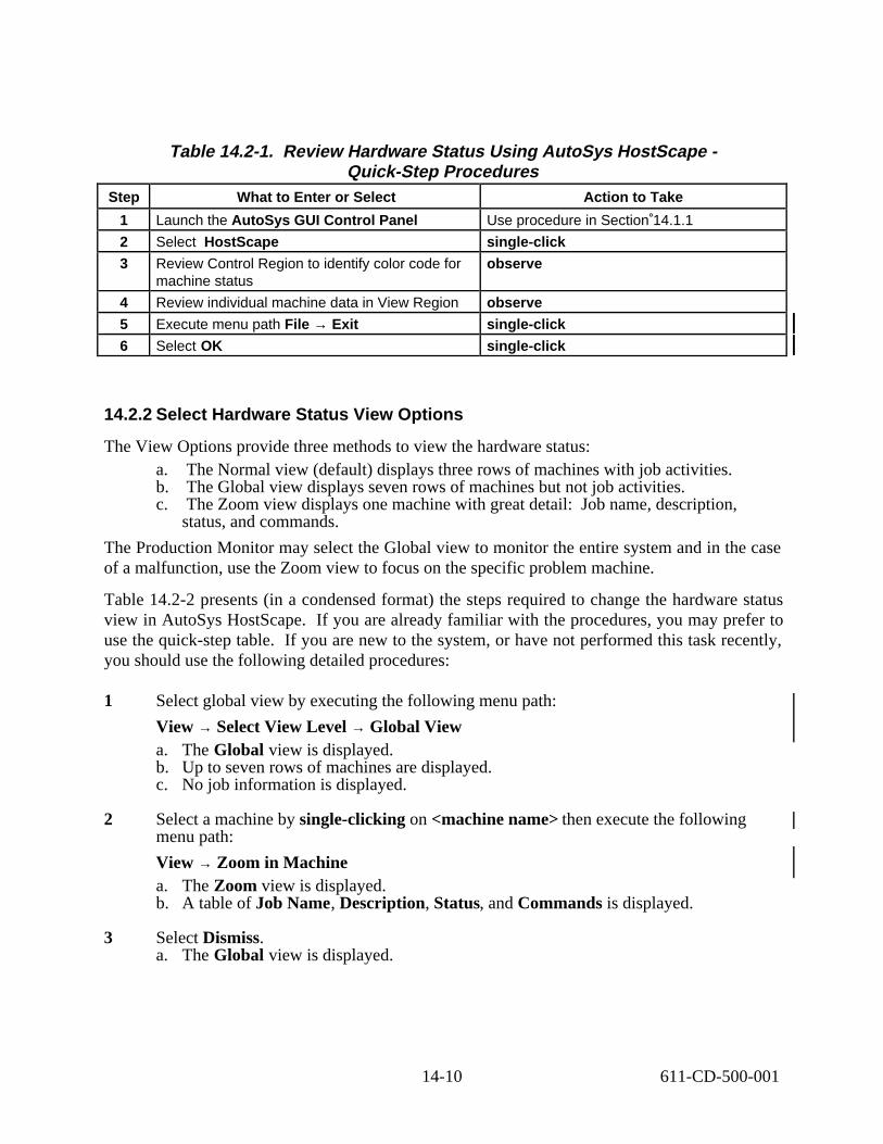
Table 14.2-1. Review Hardware Status Using AutoSys HostScape -Quick-Step Procedures
Step What to Enter or Select Action to Take
1 Launch the AutoSys GUI Control Panel Use procedure in Section 14.1.1
2 Select HostScape single-click
3 Review Control Region to identify color code for machine status
observe
4 Review individual machine data in View Region observe
5 Execute menu path File → Exit single-click
6 Select OK single-click
14.2.2 Select Hardware Status View Options
The View Options provide three methods to view the hardware status: a. The Normal view (default) displays three rows of machines with job activities. b. The Global view displays seven rows of machines but not job activities. c. The Zoom view displays one machine with great detail: Job name, description,
status, and commands.
The Production Monitor may select the Global view to monitor the entire system and in the case of a malfunction, use the Zoom view to focus on the specific problem machine.
Table 14.2-2 presents (in a condensed format) the steps required to change the hardware status view in AutoSys HostScape. If you are already familiar with the procedures, you may prefer to use the quick-step table. If you are new to the system, or have not performed this task recently, you should use the following detailed procedures:
1 Select global view by executing the following menu path:
View → Select View Level → Global View a. The Global view is displayed. b. Up to seven rows of machines are displayed. c. No job information is displayed.
2 Select a machine by single-clicking on <machine name> then execute the following menu path:
View → Zoom in Machine a. The Zoom view is displayed. b. A table of Job Name, Description, Status, and Commands is displayed.
3 Select Dismiss. a. The Global view is displayed.
14-10 611-CD-500-001

4 Display the Normal view of hardware status by executing the following menu path:
View → Select View Level → Normal view a. The Normal view is displayed. b. Up to three rows of machines are displayed. c. Limited job information is displayed.
Table 14.2-2. Change the Hardware Status View in AutoSys HostScape -Quick-Step Procedures
Step What to Enter or Select Action to Take
1 Execute menu path: View → Select View Level → Global View
single-click
2 Select < machine name> single-click
3 Execute menu path: View → Zoom in Machine single-click
4 Review individual machine data in table observe
5 Select Dismiss single-click
6 Execute menu path: View → Select View Level → Normal View
single-click
14.3 Review DPR Dependencies
The process of reviewing DPR dependencies begins with the Production Monitor launching AutoSys Jobscape. The JobScape interface is used to monitor job flow in real-time.
Table 14.3-1 presents (in a condensed format) the steps required to review DPR dependencies in AutoSys JobScape. If you are already familiar with the procedures, you may prefer to use the quick-step table. If you are new to the system, or have not performed this task recently, you should use the following detailed procedures:
1 Launch the AutoSys GUI Control Panel (refer to Section 14.1.1). a. The AutoSys GUI Control Panel is displayed.
2 Single-click on the JobScape button on the AutoSys GUI Control Panel. a. The JobScape GUI page is presented.
3 Review the Control Region (left side of display) to identify True or False Dependency Legend. a. True (default solid arrow) indicates job dependencies have been met. b. False (default dashed arrow) indicates job dependencies have not been met.
1. Dependency arrows indicate that a job dependency exists for a job. They do not define time-related starting conditions, nor do they describe the type of job dependency, such as success, failure, or running.
14-11 611-CD-500-001

4 Review the Job Display for status. The following colors represent the default values: a. White indicates job status of ACTIVATED. b. Dark Blue indicates job status of INACTIVE or ON_HOLD or ON_ICE. c. Yellow indicates job status of QUE_WAIT. d. Orange indicates job status of RESTART. e. Green indicates job status of STARTING or RUNNING. f. Red indicates job status of FAILURE or TERMINATED. g. Light Blue indicates job status of SUCCESS.
5 Review the Job Display for job types: a. Rectangle depicts Box Job. b. Ellipse depicts Command Job. c. Hexagon depicts File Watcher Job (not displayed in ECS implementation of
AutoSys).
6 Select a job by placing the cursor on a job and pressing the left mouse button. a. Border around selected job changes to yellow. b. Job name appears in Current Job Name area of the Control Region.
7 Review job descendants by placing the cursor on a job and pressing the right mouse button. a. Descendants pop-up menu appears. b. Border around selected job changes to yellow. c. Job name appears in Current Job Name area of the Control Region.
8 Select Show Children on the Descendants pop-up menu. a. Job’s first level Command and Box Jobs appear. b. Repeat Step 6 to change job selection.
9 Select Show All Descendants on the Descendants pop-up menu. a. Job’s Command and Box Jobs appear for all levels.
10 Select Hide All Descendants on the Descendants pop-up menu. a. Default view is displayed. b. All dependents are hidden.
11 Start the exit from JobScape by executing the following menu path:
File → Exit
12 Single-click on the OK button.
14-12 611-CD-500-001

Table 14.3-1. Review DPR Dependencies in AutoSys JobScape -Quick-Step Procedures
Step What to Enter or Select Action to Take
1 Launch the AutoSys GUI Control Panel Use procedure in Section 14.1.1
2 Select JobScape single-click
3 Review Control Region to identify True or False Dependency Legend and status color code
observe
4 Review the job status in View Region observe
5 Select <job name> single-click
6 Execute menu path: <job name> → Show Children
right-click
7 Review the job status in View Region observe
8 Execute menu path: <job name> → Show All Descendants
right-click
9 Review the job status in View Region observe
10 Execute menu path: <job name> → Hide All Descendants
right-click
11 Review the job status in View Region observe
12 Execute menu path File → Exit single-click
13 Select OK single-click
14.4 Review DPR Production Timeline
The process of reviewing the DPR Production Timeline begins with the Production Monitor launching AutoSys TimeScape. The TimeScape interface is used for monitoring actual versus projected job progress in real time.
Table 14.4-1 presents (in a condensed format) the steps required to review the DPR production timeline in AutoSys TimeScape. If you are already familiar with the procedures, you may prefer to use the quick-step table. If you are new to the system, or have not performed this task recently, you should use the following detailed procedures:
1 Launch the AutoSys GUI Control Panel (refer to Section 14.1.1). a. The AutoSys GUI Control Panel is displayed.
2 Single-click on the TimeScape button on the AutoSys GUI Control Panel. a. The TimeScape GUI page is presented. b. Current time is displayed in red.
3 Review Actual/Projected Legend in lower left of the Control Region and compare to View Region. a. Projected is a rectangular (blue filled) graphic, to show average job completion time. b. Actual is a striped (white and blue) ribbon, to show how much of the job has
completed. c. If stripe is green, job is running. d. If stripe is black, job has completed.
14-13 611-CD-500-001

4 Review job descendants by placing the cursor on a job and pressing the right mouse button. a. Descendants pop-up menu appears. b. An asterisk (*) indicates that a Box Job’s descendants have been hidden.
5 Select Show Children on the Descendants pop-up menu. a. Job’s first level Command and Box Jobs appear.
6 Select Show All Descendants on the Descendants pop-up menu. a. Job’s Command and Box Jobs appear with all levels.
7 Select Hide All Descendants on the Descendants pop-up menu. a. Default view is displayed.
8 Start the exit from TimeScape by executing the following menu path:
File → Exit
9 Single-click on the OK button.
Table 14.4-1. Review the DPR Production Timeline in AutoSys TimeScape -Quick-Step Procedures
Step What to Enter or Select Action to Take
1 Launch the AutoSys GUI Control Panel Use procedure in Section 14.1.1
2 Select TimeScape single-click
3 Review Control Region to identify Actual/Projected Legend and status color code
observe
4 Review the job status in View Region observe
5 Select <job name> single-click
6 Execute menu path: <job name> → Show Children
right-click
7 Review the job status in View Region observe
8 Execute menu path: <job name> → Show All Descendants
right-click
9 Review the job status in View Region observe
10 Execute menu path: <job name> → Hide All Descendants
right-click
11 Review the job status in View Region observe
12 Execute menu path File → Exit single-click
13 Select OK single-click
14-14 611-CD-500-001
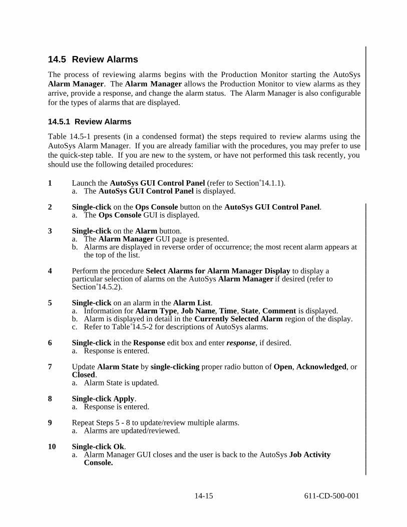
14.5 Review Alarms
The process of reviewing alarms begins with the Production Monitor starting the AutoSys Alarm Manager. The Alarm Manager allows the Production Monitor to view alarms as they arrive, provide a response, and change the alarm status. The Alarm Manager is also configurable for the types of alarms that are displayed.
14.5.1 Review Alarms
Table 14.5-1 presents (in a condensed format) the steps required to review alarms using the AutoSys Alarm Manager. If you are already familiar with the procedures, you may prefer to use the quick-step table. If you are new to the system, or have not performed this task recently, you should use the following detailed procedures:
1 Launch the AutoSys GUI Control Panel (refer to Section 14.1.1). a. The AutoSys GUI Control Panel is displayed.
2 Single-click on the Ops Console button on the AutoSys GUI Control Panel. a. The Ops Console GUI is displayed.
3 Single-click on the Alarm button. a. The Alarm Manager GUI page is presented. b. Alarms are displayed in reverse order of occurrence; the most recent alarm appears at
the top of the list.
4 Perform the procedure Select Alarms for Alarm Manager Display to display a particular selection of alarms on the AutoSys Alarm Manager if desired (refer to Section 14.5.2).
5 Single-click on an alarm in the Alarm List. a. Information for Alarm Type, Job Name, Time, State, Comment is displayed. b. Alarm is displayed in detail in the Currently Selected Alarm region of the display. c. Refer to Table 14.5-2 for descriptions of AutoSys alarms.
6 Single-click in the Response edit box and enter response, if desired. a. Response is entered.
7 Update Alarm State by single-clicking proper radio button of Open, Acknowledged, or Closed. a. Alarm State is updated.
8 Single-click Apply. a. Response is entered.
9 Repeat Steps 5 - 8 to update/review multiple alarms. a. Alarms are updated/reviewed.
10 Single-click Ok. a. Alarm Manager GUI closes and the user is back to the AutoSys Job Activity
Console.
14-15 611-CD-500-001

11 Start the exit from the AutoSys Job Activity Console (Ops Console) by executing the following menu path:
File → Exit
12 Single-click on the OK button.
Table 14.5-1. Review Alarms Using the AutoSys Alarm Manager -Quick-Step Procedures
Step What to Enter or Select Action to Take
1 Launch the AutoSys GUI Control Panel Use procedure in Section 14.1.1
2 Select Ops Console single-click
3 Select Alarm single-click
4 Select alarms for Alarm Manager display if desired
Use procedure in Section 14.5.2 if applicable
5 Select an alarm in the Alarm List single-click
6 Enter a response in the Response edit box if desired.
enter text
7 Update the Alarm State by selecting the proper radio button (Open, Acknowledged, or Closed)
single-click
8 Select Apply single-click
9 Repeat Steps 4 through 7 to review/update additional alarms
10 Select Ok single-click
11 Execute menu path File → Exit single-click
12 Select OK single-click
14-16 611-CD-500-001

Table 14.5-2. AutoSys Alarms (1 of 2) ALARM CODE* DESCRIPTION
AUTO_PING The autoping command has found a problem in trying to communicate with the Remote Agent on a client machine.
CHASE 514 The chase command has found a problem with a job that is supposedly running. The job and problem are listed.
DATABASE_COMM 516 The Remote Agent had trouble sending an event to the database. The job probably ran successfully. Inspect the Remote Agent Log file to determine what happened.
DB_PROBLEM 523 There is a problem with one of the AutoSys databases. This alarm can trigger a user-specified notification procedure.
DB_ROLLOVER 519 AutoSys has rolled over from Dual Server to Single Server Mode. This alarm can trigger a user-specified notification procedure.
DUPLICATE_EVENT 524 Duplicate events have been received in the Event Server. Typically, this means that two Event Processors are running, although “duplicate events” can also be caused by Event Server configuration errors.
EP_HIGH_AVAIL 522 The Event Processor High Availability system has detected some system or network problems. This alarm can trigger a user-specified notification procedure.
EP_ROLLOVER 520 The Shadow Event Processor is taking over processing. This alarm can trigger a user-specified notification procedure.
EP_SHUTDOWN 521 The Event Processor is shutting down. This may be due to a normal shutdown (SEND_EVENT) or due to an error condition. This alarm can trigger a user-specified notification procedure.
EVENT_HDLR_ERROR 507 The Event Processor had an error while processing an event. The job associated with the event should be inspected to see if manual intervention is required.
EVENT_QUE_ERROR 508 An event could not be marked as processed. This is usually due to a problem with the Event Server.
FORKFAIL 501 The Remote Agent was unable to start the user command because it was unable to get a process slot on the machine. AutoSys automatically attempts a RESTART when this happens.
INSTANCE_UNAVAILABLE 525 When different AutoSys instances communicate with each other, this alarm is generated when a receiving AutoSys instance (i.e., its Event Server) cannot be reached. The Event Server is probably down.
JOBFAILURE 503 A job has failed. Its current status is FAILURE.
JOBNOT_ONICEHOLD 509 To place a job either ON_HOLD or ON_ICE, a JOB_ON_HOLD or JOB_ON_ICE event (as applicable) is sent. There are certain conditions when the job cannot be placed ON_HOLD or ON_ICE (e.g., if it is already running). In such cases the alarm is sent alerting the operator that the job could not be put ON_HOLD or ON_ICE (as applicable).
14-17 611-CD-500-001

Table 14.5-2. AutoSys Alarms (2 of 2) ALARM CODE* DESCRIPTION
MAXRUNALARM 510 The job has been running for a time greater than that defined in the Maximum Run Alarm (max_run_alarm) field for the job. The job may continue to run; however, a warning alarm is generated.
MAX_RETRYS 505 AutoSys continues attempting to restart a job if there are system problems or if the job is configured for application restarts (n_retrys). There is a limit to the number of times it will attempt a restart, as defined in the configuration files (using MaxRestartTrys). When that limit has been reached, the MAX_RETRYS alarm is sent to alert operators that AutoSys has given up trying to start the job. After the problem has been fixed the job must be started manually.
MINRUNALARM 502 The job has completed running in a time less than that defined in the Minimum Run Alarm (min_run_alarm) field for the job.
MISSING_HEARTBEAT 513 A job has not sent a HEARTBEAT within the interval specified for the job. The operator should inspect the job to determine the cause.
RESOURCE 512 A resource needed for the job was not available. The types of resources are: (a) number of process slots and (b) file space. Specific information about the problem is in the comment associated with the alarm. If AutoSys encounters a resource problem, it attempts to restart the job after a suitable delay.
STARTJOBFAIL 506 AutoSys was unable to start the job. This is generally due to communication problems with the remote machine. AutoSys attempts to restart the job.
VERSION_MISMATCH 518 Generated by the Remote Agent when calling the routine (e.g., Event Processor, chase, clean_files, autoping, etc.) has a different version number than the Remote Agent. Inspect the Remote Agent Log file for the exact version mismatch. The proper Remote Agent version should be installed.
*The code number is used for viewing the event in the event table in the AutoSys database.
14.5.2 Select Alarms for Alarm Manager Display
Table 14.5-3 presents (in a condensed format) the steps required to select the types of alarms to be displayed on the AutoSys Alarm Manager for controlling which alarms are displayed. If you are already familiar with the procedures, you may prefer to use the quick-step table. If you are new to the system, or have not performed this task recently, you should use the following detailed procedures:
1 Launch the AutoSys GUI Control Panel (refer to Section 14.1.1). a. The AutoSys GUI Control Panel is displayed.
2 Single-click on the Ops Console button on the AutoSys GUI Control Panel. a. The Ops Console GUI is displayed.
14-18 611-CD-500-001
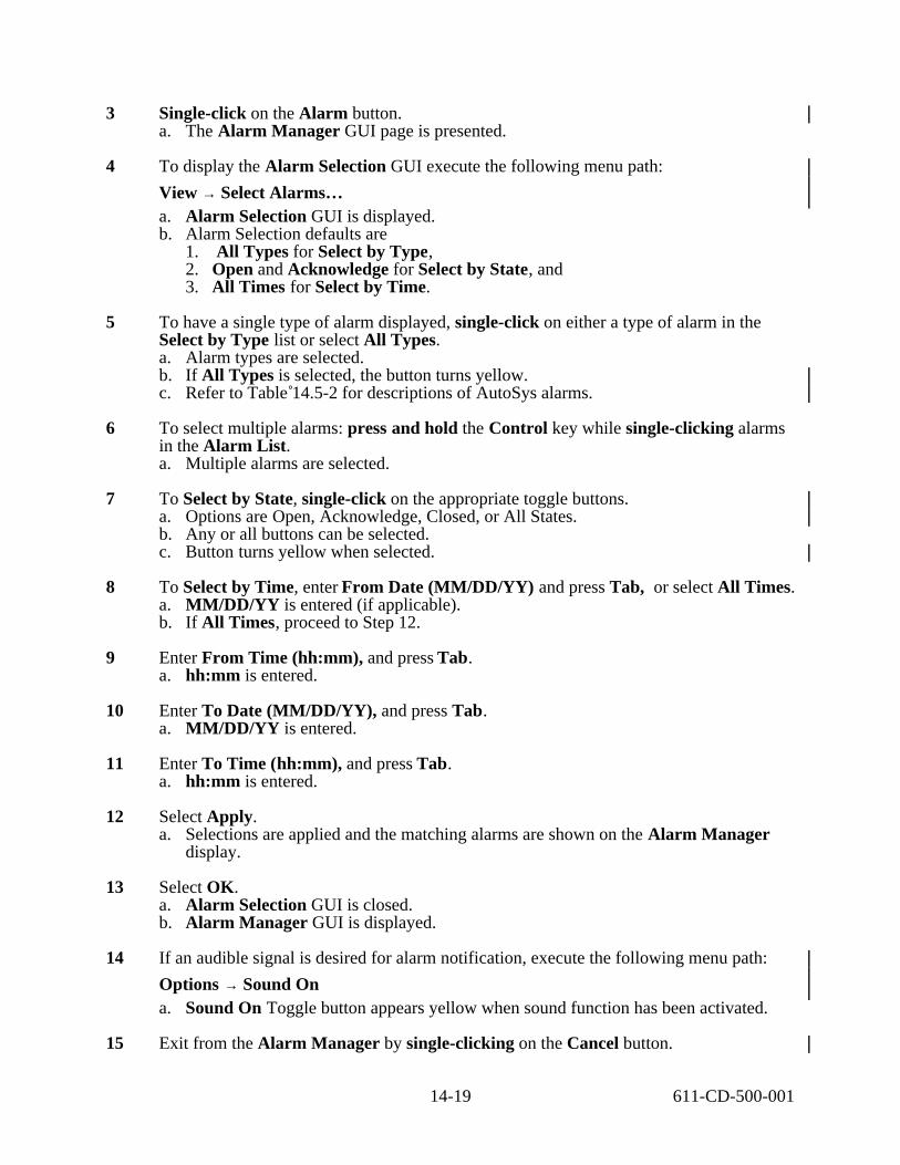
3 Single-click on the Alarm button. a. The Alarm Manager GUI page is presented.
4 To display the Alarm Selection GUI execute the following menu path:
View → Select Alarms… a. Alarm Selection GUI is displayed. b. Alarm Selection defaults are
1. All Types for Select by Type, 2. Open and Acknowledge for Select by State, and 3. All Times for Select by Time.
5 To have a single type of alarm displayed, single-click on either a type of alarm in the Select by Type list or select All Types. a. Alarm types are selected. b. If All Types is selected, the button turns yellow. c. Refer to Table 14.5-2 for descriptions of AutoSys alarms.
6 To select multiple alarms: press and hold the Control key while single-clicking alarms in the Alarm List. a. Multiple alarms are selected.
7 To Select by State, single-click on the appropriate toggle buttons. a. Options are Open, Acknowledge, Closed, or All States. b. Any or all buttons can be selected. c. Button turns yellow when selected.
8 To Select by Time, enter From Date (MM/DD/YY) and press Tab, or select All Times. a. MM/DD/YY is entered (if applicable). b. If All Times, proceed to Step 12.
9 Enter From Time (hh:mm), and press Tab. a. hh:mm is entered.
10 Enter To Date (MM/DD/YY), and press Tab. a. MM/DD/YY is entered.
11 Enter To Time (hh:mm), and press Tab. a. hh:mm is entered.
12 Select Apply. a. Selections are applied and the matching alarms are shown on the Alarm Manager
display.
13 Select OK. a. Alarm Selection GUI is closed. b. Alarm Manager GUI is displayed.
14 If an audible signal is desired for alarm notification, execute the following menu path:
Options → Sound On a. Sound On Toggle button appears yellow when sound function has been activated.
15 Exit from the Alarm Manager by single-clicking on the Cancel button.
14-19 611-CD-500-001

Table 14.5-3. Select Types of Alarms to be Displayed on the AutoSys Alarm Manager - Quick-Step Procedures
Step What to Enter or Select Action to Take
1 Launch the AutoSys GUI Control Panel Use procedure in Section 14.1.1
2 Select Ops Console single-click
3 Select Alarm single-click
4 Execute menu path: View → Select Alarms.... single-click
5 Select type(s) of alarms to be displayed from the Select by Type list or select All Types
single-click
6 Select state(s) of alarms to be displayed from the Select by State list or select All States
single-click
7 Select All Times for time(s) of alarms to be displayed or enter dates and times (From/To)
single-click or enter text, press Tab
8 Select Apply single-click
9 Select Ok single-click
10 Execute menu path: Options → Sound On if desired
single-click if applicable
11 Select Cancel single-click
14.6 Review Job Activities
During start-up, the Job Management server in the Data Processing Subsystem determines the number of jobs in the PDPS database associated with Job Management’s operating mode and compares the number with the maximum allowable for the mode. The maximum is specified in the Job Management configuration file (i.e., as DpPrAutoSysMaxJobs in EcDpPrJobMgmt.CFG). Job Management deletes from AutoSys the successfully completed jobs associated with the applicable mode only. Deleting completed jobs makes room for other jobs in the processing queue. It is possible to distribute the optimum number of jobs among the active modes according to their level of activity (refer to Section 14.10.2).
The process of reviewing Job Activities begins with the Production Monitor launching the AutoSys GUI Control Panel. The Job Activity Console (Ops Console), which is accessible from the control panel, is the primary interface that allows the operator to monitor all jobs that are defined to AutoSys. The Job Selection GUI sets the criteria for jobs to be displayed on the Job Activity Console.
14.6.1 Specify Job Selection Criteria
Table 14.6-1 presents (in a condensed format) the steps required to filter (select) jobs to be displayed on the Job Activity Console (Ops Console) GUI. If you are already familiar with the procedures, you may prefer to use the quick-step table. If you are new to the system, or have not performed this task recently, you should use the following detailed procedures:
1 Launch the AutoSys GUI Control Panel (refer to Section 14.1.1). a. The AutoSys GUI Control Panel is displayed.
14-20 611-CD-500-001

2 Single-click on the Ops Console button on the AutoSys GUI Control Panel. a. The AutoSys Job Activity Console (Ops Console) is displayed. b. No job information is displayed on the Job Activity Console when it is brought up
using the Ops Console button on the AutoSys GUI Control Panel.
3 To display the Job Selection GUI execute the following menu path:
View → Select Jobs a. The Job Selection view is displayed. b. Job selection has the following default settings:
1. All Jobs (Job Name) for Select by Name. 2. All Statuses for Select by Status. 3. All Machines for Select by Machine. 4. Unsorted for Sort Order.
4 Single-click on the desired option in the Select by Name area, and enter required name or select All Jobs. c. Options are Job Name, Box Name, or Box Levels or All Jobs. d. Selection button turns yellow.
5 Single-click desired status in the Select by Status area e. Options are Starting, Running, Success, Failure, Terminated, Restart, Que Wait,
Activated, Inactive, On Hold, and On Ice.
6 Single-click desired machine in Select by Machine area or select All Machines. a. Machine is highlighted. b. All Machines button turns yellow.
7 Single-click desired Sort Order. a. Options are Start Time, End Time, Job Name, Job Status, Machine Name, and
Unsorted.
8 Single-click on the Apply button. a. Selections are applied.
9 Single-click on the OK button. a. Job Activity Console (Ops Console) is displayed. b. Job List is displayed in accordance with the specified selection criteria.
14-21 611-CD-500-001

Table 14.6-1. Specify Job Selection Criteria for the AutoSys Job Activity Console -Quick-Step Procedures
Step What to Enter or Select Action to Take
1 Launch the AutoSys GUI Control Panel Use procedure in Section 14.1.1
2 Select Ops Console single-click
3 Execute menu path: View ‚ Select Jobs single- click
4 Select the desired option in the Select by Name area and enter required name if applicable
single-click; enter text if applicable
5 Select the desired status(es) in the Select by Status area
single-click
6 Select the desired machine(s) in Select by Machine area
single-click
7 Select the desired Sort Order single-click
8 Select Apply single-click
9 Select OK single-click
14.6.2 Review Job Activities Using the AutoSys Job Activity Console
Table 14.6-2 presents (in a condensed format) the steps required to review job activities using the AutoSys Job Activity Console. If you are already familiar with the procedures, you may prefer to use the quick-step table. If you are new to the system, or have not performed this task recently, you should use the following detailed procedures:
1 Specify job selection criteria for the AutoSys Job Activity Console - Refer to Section 14.6.1.
2 Review jobs in the Job List region of the Job Activity Console. a. Job Name, Description, Status, Commands, and Machine are displayed in a table.
3 Single-click anywhere on a job row to display detailed information. a. Job details are displayed in the Currently Selected Job region of the Job Activity
Console.
4 Review the data in the Currently Selected Job region of the display. a. Job name (Currently Selected Job), Description, Command, Start Time (and
date), End Time (and date), Run Time, Status, Exit Code, Next Start, Machine, Queue Name, Priority, and Num. of Tries are displayed in a table.
5 Review Starting Conditions. a. All job Starting Conditions are displayed. b. Individual (atomic) starting conditions are displayed, including Atomic Condition,
Current State, and T/F (whether the current state evaluates true or false) are displayed.
c. Single-clicking on a specific starting condition causes the Currently Selected Job to be updated to reflect the selected “upstream” dependency.
6 Review the Job Report region.
14-22 611-CD-500-001

a. Single-click on the Summary, Event, and None buttons in the Reports area to view different reports.
b. Summary, Event, and Job Reports are displayed as selected. c. Selected report button turns yellow.
7 Single-click Exit. a. AutoSys JAC Exit GUI appears.
8 Single-click OK. a. AutoSys Job Activity Console (Ops Console) GUI is exited.
Table 14.6-2. Review Job Activities Using the AutoSys Job Activity Console -Quick-Step Procedures
Step What to Enter or Select Action to Take
1 Specify job selection criteria for the Job Activity Console
Use procedure in Section 14.6.1
2 Review jobs in the Job List region observe
3 Select a job row for which detailed information is to be displayed
single-click
4 Review the data in the Currently Selected Job region
observe
5 Review the data in the Starting Conditions region
observe
6 Review reports in the Job Reports region single-click
7 Select Exit single-click
8 Select OK single-click
14.7 Modify Job Status
At times the Production Monitor may need to modify a particular job in any of the following ways:
a. Start the job. b. Kill the job. c. Force the job to start. d. Place the job on hold. e. Take the job off hold.
The Production Monitor has the option of the following three methods for making those types of modifications to a particular job:
a. Buttons in the Actions region of the Job Activity Console (Ops Console). b. Menu accessed by clicking the right mouse button on the relevant job name on either
the JobScape or TimeScape GUI. c. AutoSys Send Event GUI.
In addition to the previously mentioned modifications to job status, the buttons in the Actions region of the Job Activity Console (Ops Console) allow the Production Monitor to generate one of the following types of reports:
14-23 611-CD-500-001
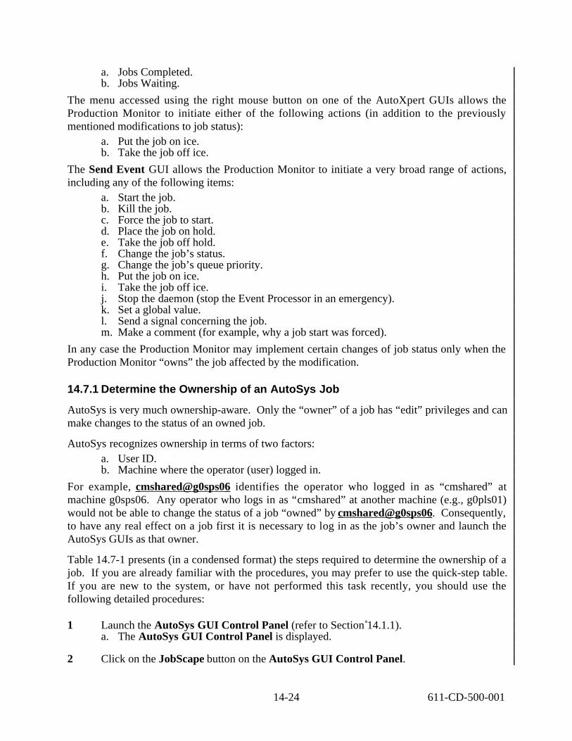
a. Jobs Completed. b. Jobs Waiting.
The menu accessed using the right mouse button on one of the AutoXpert GUIs allows the Production Monitor to initiate either of the following actions (in addition to the previously mentioned modifications to job status):
a. Put the job on ice. b. Take the job off ice.
The Send Event GUI allows the Production Monitor to initiate a very broad range of actions, including any of the following items:
a. Start the job. b. Kill the job. c. Force the job to start. d. Place the job on hold. e. Take the job off hold. f. Change the job’s status. g. Change the job’s queue priority. h. Put the job on ice. i. Take the job off ice. j. Stop the daemon (stop the Event Processor in an emergency). k. Set a global value. l. Send a signal concerning the job. m. Make a comment (for example, why a job start was forced).
In any case the Production Monitor may implement certain changes of job status only when the Production Monitor “owns” the job affected by the modification.
14.7.1 Determine the Ownership of an AutoSys Job
AutoSys is very much ownership-aware. Only the “owner” of a job has “edit” privileges and can make changes to the status of an owned job.
AutoSys recognizes ownership in terms of two factors: a. User ID. b. Machine where the operator (user) logged in.
For example, cmshared@g0sps06 identifies the operator who logged in as “cmshared” at machine g0sps06. Any operator who logs in as “cmshared” at another machine (e.g., g0pls01) would not be able to change the status of a job “owned” by cmshared@g0sps06. Consequently, to have any real effect on a job first it is necessary to log in as the job’s owner and launch the AutoSys GUIs as that owner.
Table 14.7-1 presents (in a condensed format) the steps required to determine the ownership of a job. If you are already familiar with the procedures, you may prefer to use the quick-step table. If you are new to the system, or have not performed this task recently, you should use the following detailed procedures:
1 Launch the AutoSys GUI Control Panel (refer to Section 14.1.1). a. The AutoSys GUI Control Panel is displayed.
2 Click on the JobScape button on the AutoSys GUI Control Panel.
14-24 611-CD-500-001

a. The JobScape GUI is displayed.
3 Place the mouse cursor on the relevant job and single-click and hold the right mouse button. a. Descendants pop-up menu appears. b. Options are Show Children, Show All Descendants, Hide All Descendants, Show
Job Arrows, Hide Job Arrows, Show Box Arrows, Hide Box Arrows, Job Definition, View Dependencies, Set Simulation Overrides [grayed out], Start Job, Kill Job, Force Start Job, On Hold, Off Hold, On Ice, Off Ice.
4 Select Job Definition from the Descendants pop-up menu (release the right mouse button). a. The Job Definition GUI is displayed.
5 Review the entry in the Owner field of the Job Definition GUI. a. Job owner is identified in the Owner field of the Job Definition GUI. b. Job name is listed in the Job Name field of the Job Definition GUI.
NOTE: Jobs should not be deleted using the AutoSys Job Definition GUI because it does not communicate with the PDPS database.
6 To exit from the Job Definition GUI, single-click on the Exit button.
Table 14.7-1. Determine the Ownership of an AutoSys Job - Quick-Step Procedures (1 of 2)
Step What to Enter or Select Action to Take
1 Launch the AutoSys GUI Control Panel Use procedure in Section 14.1.1
2 Select JobScape single-click
3 Select <job name> single-click
4 Execute menu path <job name> → Job Definition
right-click
5 Review the job owner information in the Owner field
observe
6 Select Exit to quit Job Definition single-click
14.7.2 Modify Job Status
The process of modifying job status begins after the Production Monitor has selected the Job Activity Console (Ops Console).
Table 14.7-2 presents (in a condensed format) the steps required to modify job status using the AutoSys Job Activity Console. If you are already familiar with the procedures, you may prefer to use the quick-step table. If you are new to the system, or have not performed this task recently, you should use the following detailed procedures:
14-25 611-CD-500-001

1 Specify job selection criteria for the AutoSys Job Activity Console - Refer to Section 14.6.1.
2 Verify that the job with the status to be modified is listed in the Currently Selected Job field of the Job Activity Console (Ops Console) . a. Single-click on the job row in the Job List region of the Job Activity Console if
necessary. 1. Information concerning the selected job is displayed in the Currently Selected
Job region of the Job Activity Console.
3 Single-click on the button corresponding to the desired action to be taken with respect to the selected job (if there is a corresponding button in the Actions region of the Job Activity Console). a. Options are Start Job, Kill Job, Force Start Job, [Put Job} On Hold, [Take Job]
Off Hold, [Display] Jobs Completed [Report], [Display] Jobs Waiting [Report]. 1. If one of the buttons in the preceding list was selected, the procedure has been
completed. b. If there is no button corresponding to the desired action, modify job status using
either the Send Event GUI (continue with the next step) or the Client Tool button. 1. If Send Event was selected, perform Steps 4 through 16 as applicable. 2 . Procedures for performing job management functions using the Client Tool
button are described in Section 14.7.3.
4 Single-click on the Send Event button in the Actions Region of the Job Activity Console. a. Send Event GUI is displayed. b. Send Event defaults are:
1. Start Job for Event Type. 2. Now for Time. 3. Normal for Send Priority.
5 Single-click on the Event Type to be sent to the job in AutoSys. a. Options are Start Job, Job On Hold, Job Off Hold, Comment, Stop Demon, Force
Start Job, Job On Ice, Job Off Ice, Kill Job, Change Status, Change Priority, Set Global, and Set Signal.
6 Verify <Job Name>. a. <Job Name> appears in the Job Name field. b. Enter the proper <Job Name> if incorrect.
7 Enter the desired date and time, either Now or Future. a. Single-click Now or single-click Future and enter Date (MM/DD/YY), Time
(hh:mm), and single-click A.M. or P.M. 1. Now for immediate execution. 2. Future for future time and date. (Current date and time are default values.)
8 Enter a <comment> if desired or necessary. a. Free-form field for text entry to associate with the event being sent to the specified
job.
9 Review the AUTOSERV Instance field. a. Displays the current AutoSys instance identifier. b. Enter the proper <AUTOSERV Instance> if incorrect.
14-26 611-CD-500-001

10 Review the Global Name and Global Value fields if Set Global was selected as the Event Type. a. Enter the <Global Name> and <Global Value> if applicable.
11 Review the Signal field if either Send Signal or Kill Job was selected as the Event Type. a. Enter the number of the UNIX signal to be sent to the job (refer to Table 14.7-3).
12 Review the Status option menu if Change Status was selected as the Event Type. a. Single-click and select from pop-up list desired status.
1. Options are: Running, Success, Failure, Terminated, Starting, and Inactive. 2. Can be changed only if Change Status was selected in the Event Type region.
13 Review the Queue Priority entry if Change Priority was selected as the Event Type. a. Can be changed only if Change Priority was selected in the Event Type region. b. Enter the new <Queue Priority> if applicable.
14 Review the Send Priority radio box. a. Refers to the priority for sending the selected event to the job. b. Options are Normal and High. c. High priority is reserved for emergencies.
15 Single-click on the Execute button.
16 Single-click on the Yes button. a. Send Event setting is set. b. Job Activity Console is displayed.
Table 14.7-2. Modify Job Status – Quick-Step Procedures (1 of 2) Step What to Enter or Select Action to Take
1 Specify job selection criteria for the Job Activity Console Use procedure in Section 14.6.1
2 Review jobs in the Job List region observe
3 Select a job row for which detailed information is to be displayed
single-click
4 Select the button corresponding to the desired action to be taken
single-click
5 If there is no button corresponding to the desired action, select the Send Event button
single-click
6 If the Send Event GUI was invoked, select the Event Type to be sent to the job
single-click
7 Verify job name in the Job Name field enter text if necessary
8 Select either Now or Future and enter the desired date and time if Future was selected
single-click; enter text if applicable
9 Enter a <comment> in the Comment field if desired or necessary
enter text
10 Enter the <AUTOSERV Instance> if incorrect enter text if necessary
11 Enter the <Global Name> and <Global Value> if Set Global was selected as the Event Type
enter text if applicable
14-27 611-CD-500-001

1
2
3
4
5
6
7
8
9
10
11
12
13
14
15
16
17
18
19
20
21
22
23
24
25
26
27
28
29
Table 14.7-2. Modify Job Status – Quick-Step Procedures (2 of 2) Step What to Enter or Select Action to Take
12 Enter the appropriate number in the Signal field if either Send Signal or Kill Job was selected as the Event Type
enter text if applicable
13 Select the Status if Change Status was selected as the Event Type
single-click if applicable
14 Enter the <Queue Priority> if Change Priority was selected as the Event Type
enter number if applicable
15 Select the Send Priority status single-click if applicable
16 Select Execute single-click
17 Select Yes single-click
Table 14.7-3. UNIX Signals (1 of 2) NAME VALUE DEFAULT EVENT
HUP Exit Hangup.
INT Exit Interrupt.
QUIT Core Quit.
ILL Core Illegal Instruction.
TRAP Core Trace/Breakpoint Trap.
ABRT Core Abort.
EMT Core Emulation Trap.
FPE Core Arithmetic Exception.
KILL Exit Killed.
BUS Core Bus Error.
SEGV Core Segmentation Fault.
SYS Core Bad System Call.
PIPE Exit Broken Pipe.
ALRM Exit Alarm Clock.
TERM Exit Terminated.
USR1 Exit User Signal 1.
USR2 Exit User Signal 2.
CHLD Ignore Child Status Changed.
PWR Ignore Power Fail/Restart.
WINCH Ignore Window Size Change
URG Ignore Urgent Socket Condition.
POLL Exit Pollable Event.
STOP Stop Stopped (signal).
TSTP Stop Stopped (user).
CONT Ignore Continued.
TTIN Stop Stopped (tty input).
TTOU Stop Stopped (tty output).
VTALRM Exit Virtual Timer Expired
PROF Exit Profiling Timer Expired.
14-28 611-CD-500-001

Table 14.7-3. UNIX Signals (2 of 2) NAME VALUE DEFAULT EVENT
XCPU 30 Core CPU time limit exceeded.
XFSZ 31 Core File size limit exceeded.
WAITING 32 Ignore Concurrency signal reserved by threads library
LWP 33 Ignore Inter-LWP signal reserved by threads library.
FREEZE 34 Ignore Check point Freeze
THAW 35 Ignore Check point Thaw
CANCEL 36 Ignore Cancellation signal reserved by threads library.
RTMIN * Exit First real time signal
(RTMIN+1) * Exit Second real time signal
(RTMAX-1) * Exit Second-to-last real time signal.
RTMAX * Exit Last real time signal *The symbols RTMIN through RTMAX are evaluated dynamically in order to permit future
configurability.
14.7.3 Cancel a Sent Event
Table 14.7-4 presents (in a condensed format) the steps required to cancel an event that was previously scheduled for sometime in the future. If you are already familiar with the procedures, you may prefer to use the quick-step table. If you are new to the system, or have not performed this task recently, you should use the following detailed procedures:
1 Single-click on the Send Event button in the Actions Region of the Job Activity Console. a. Send Event GUI is displayed.
2 Single-click on the Event Type that was sent to the job and is to be cancelled. a. Options are Start Job, Job On Hold, Job Off Hold, Comment, Stop Demon, Force
Start Job, Job On Ice, Job Off Ice, Kill Job, Change Status, Change Priority, Set Global, and Set Signal.
3 Single-click on the Cancel Previously Sent Event radio button.
4 Verify Job Name. a. <Job Name> appears in the Job Name field. b. Enter the proper <Job Name> if incorrect.
5 Single-click on the Execute button.
6 Single-click on the Yes button. a. The event is cancelled. b. Job Activity Console is displayed.
14-29 611-CD-500-001

Table 14.7-4. Cancel a Sent Event - Quick-Step Procedures Step What to Enter or Select Action to Take
1 Select the Send Event button single-click
2 Select the Event Type that was sent to the job and is to be cancelled
single-click
3 Select the Cancel Previously Sent Event button single-click
4 Verify job name in the Job Name field enter text if necessary
5 Select Execute single-click
6 Select Yes single-click
14.7.4 Perform Job Management Functions
The Job Management Client tool is a set of utility programs intended primarily for use by software developers. However, if necessary, it is possible to gain access to the following Job Management Client functions from AutoSys by clicking on the Client Tool button in the Actions region of the Job Activity Console:
a. Create DPR Job. b. Release DPR Job. c. Cancel DPR Job. d. Change DPR ID. e. View Job Management DPR Queue. f. Create Ground Event Job. g. Cancel Ground Event Job.
Table 14.7-5 presents (in a condensed format) the steps required to perform job management functions using the AutoSys Job Activity Console. If you are already familiar with the procedures, you may prefer to use the quick-step table. If you are new to the system, or have not performed this task recently, you should use the following detailed procedures:
1 Verify that the job with the status to be modified is listed in the Currently Selected Job field of the Job Activity Console (Ops Console) . a. Single-click on the job row in the Job List region of the Job Activity Console if
necessary. 1. Information concerning the selected job is displayed in the Currently Selected
Job region of the Job Activity Console.
2 Single-click on the Client Tool button in the Actions Region of the Job Activity Console. a. The Ready to Invoke [Job Management Client] dialog box is displayed.
3 Single-click yes. a. The dialog box closes. b. The Jobs Activation User Interface window is displayed. c. The following menu options are displayed:
0) Exit1) Create Dpr Job2) Release Dpr Job
14-30 611-CD-500-001
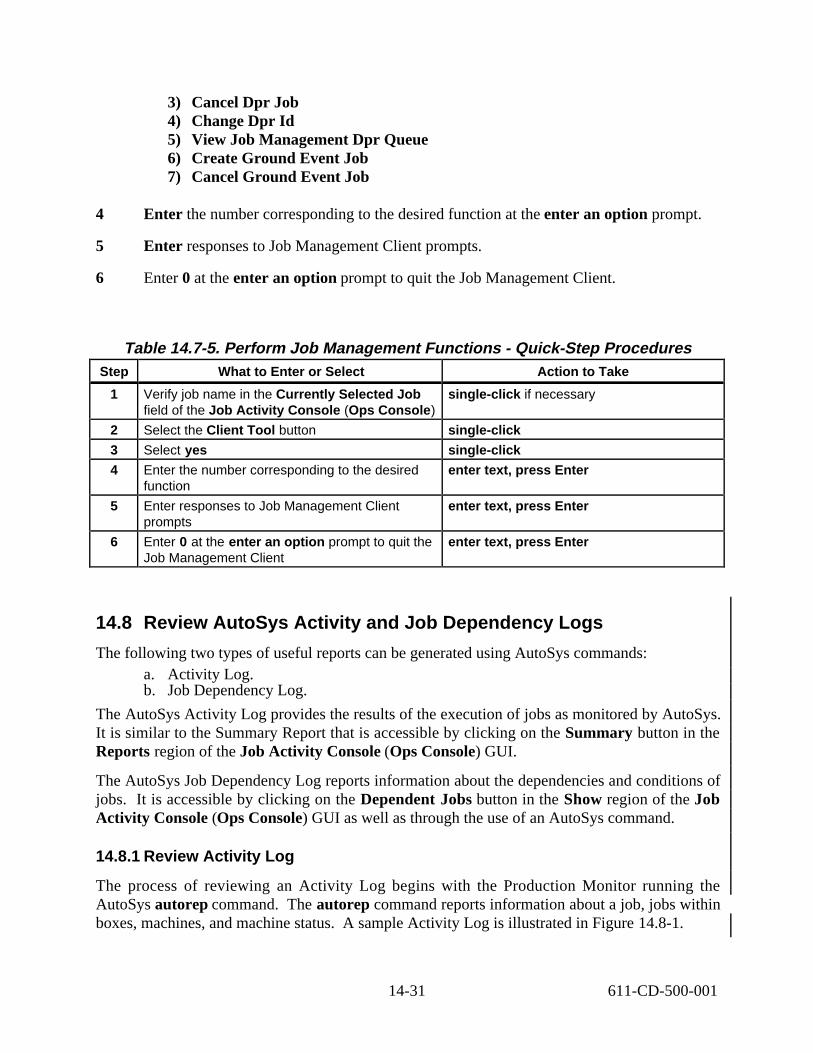
3) Cancel Dpr Job4) Change Dpr Id5) View Job Management Dpr Queue6) Create Ground Event Job7) Cancel Ground Event Job
4 Enter the number corresponding to the desired function at the enter an option prompt.
5 Enter responses to Job Management Client prompts.
6 Enter 0 at the enter an option prompt to quit the Job Management Client.
Table 14.7-5. Perform Job Management Functions - Quick-Step Procedures Step What to Enter or Select Action to Take
1 Verify job name in the Currently Selected Job field of the Job Activity Console (Ops Console)
single-click if necessary
2 Select the Client Tool button single-click
3 Select yes single-click
4 Enter the number corresponding to the desired function
enter text, press Enter
5 Enter responses to Job Management Client prompts
enter text, press Enter
6 Enter 0 at the enter an option prompt to quit the Job Management Client
enter text, press Enter
14.8 Review AutoSys Activity and Job Dependency Logs
The following two types of useful reports can be generated using AutoSys commands: a. Activity Log. b. Job Dependency Log.
The AutoSys Activity Log provides the results of the execution of jobs as monitored by AutoSys. It is similar to the Summary Report that is accessible by clicking on the Summary button in the Reports region of the Job Activity Console (Ops Console) GUI.
The AutoSys Job Dependency Log reports information about the dependencies and conditions of jobs. It is accessible by clicking on the Dependent Jobs button in the Show region of the Job Activity Console (Ops Console) GUI as well as through the use of an AutoSys command.
14.8.1 Review Activity Log
The process of reviewing an Activity Log begins with the Production Monitor running the AutoSys autorep command. The autorep command reports information about a job, jobs within boxes, machines, and machine status. A sample Activity Log is illustrated in Figure 14.8-1.
14-31 611-CD-500-001

Job Name _________________________________________________________________
Nightly_Download Watch_4_file filter_data update_DBMS
Pri/Xit Run Status Last End Last Start
170/1 11/10 17:00 11/10 17:52 SUCCESS 101/1 11/10 17:00 11/10 17:00 SUCCESS 101/1 11/10 17:00 11/10 17:00 SUCCESS 101/1 11/10 17:00 11/10 17:00 SUCCESS
Figure 14.8-1. Sample Activity Log
Table 14.8-1 presents (in a condensed format) the steps required to display and review the Activity Log using the AutoSys autorep command. If you are already familiar with the procedures, you may prefer to use the quick-step table. If you are new to the system, or have not performed this task recently, you should use the following detailed procedures:
1 At the UNIX command line prompt enter:
/usr/ecs/<MODE>/COTS/autosys/bin/autorep -J ALL a. Directory path may vary with installation. b. Activity Log is displayed on the UNIX standard output. c. Enter <job name> in place of ALL for a specific job. d. Enter -M <machine name> for a Machine Report. e. Enter -s for a summary report. f. Enter -d for a Detailed Report. g. Enter -q for a Query Report.
2 Add | lp to the preceding command line to print the document or add > /<path>/<filename> to save the report in a file. a. Activity Log is printed or saved in a file as applicable.
3 Review the Activity Log to determine job states. a. Completed. b. Currently running. c. In the queue.
Table 14.8-1. Review Activity Log - Quick-Step Procedures Step What to Enter or Select Action to Take
1 Enter /usr/ecs/<MODE>/COTS/autosys/bin/autorep -J ALL
enter text, press Enter
2 Review the Activity Log to determine job states Observe
14-32 611-CD-500-001

14.8.2 Review Job Dependency Log
The process of reviewing a Job Dependency Log begins with the Production Monitor running the AutoSys job_depends command. The job_depends command reports information about the dependencies and conditions of a job. The command can be used to determine the current state of a job, its job dependencies, the dependencies and nested hierarchies (for boxes) as specified in the job definition, and a forecast of what jobs will run during a given period of time. A sample Job Dependency Log is illustrated in Figure 14.8-2.
Job Name Status Date Cond? Start Cond? Dependent Jobs?
DPR## Activated No Yes No
Condition:
Atomic Condition Current Status T/F
SUCCESS(SPR_##) SUCCESS T
EXIT_CODE(execute.DPR_##) SUCCESS F
(success(DPR_##) and exit code(execute.DPR_##)<5)
Figure 14.8-2. Sample Job Dependency Log
Table 14.8-2 presents (in a condensed format) the steps required to display and review the Job Dependency Log using the AutoSys job_depends command. If you are already familiar with the procedures, you may prefer to use the quick-step table. If you are new to the system, or have not performed this task recently, you should use the following detailed procedures:
1 At the UNIX command line prompt enter:
/usr/ecs/<MODE>/COTS/autosys/bin/job_depends -c -J <job name> a. Directory path may vary with installation. b. Job Dependency log is displayed. c. Enter -c for current condition status. d. Enter -d for dependencies only. e. Enter -t for time dependencies. f. Enter -J <job name> to indicate a specific job as the subject of the report. Use ALL
for all jobs.
14-33 611-CD-500-001

2 Add | lp to the preceding command line to print the document or add > /<path>/<filename> to save the report in a file. a. Job Dependency log is printed or saved in a file as applicable.
3 Review the Job Dependency Log to determine job dependencies.
Table 14.8-2. Review Job Dependency Log - Quick-Step Procedures Step What to Enter or Select Action to Take
1 Enter /usr/ecs/<MODE>/COTS/autosys/bin/job_depe nds -c -J <job name>
enter text, press Enter
2 Review the Job Dependency Log to determine job dependencies
observe
14.9 Define and Run Monitors/Browsers
The current edition of the Release 5A Operations Tools Manual for the ECS Project (609-CD-500-001) indicates that ECS does not support the AutoSys monitor/browser capabilities. However, they are functional and the Production Monitor can use them (with no expectation of ECS support if problems are encountered).
The process of defining monitors/browsers begins with the Production Monitor launching AutoSys. The Monitor/ Browser screen contains fields representing all the information needed to define a monitor or browser. See Figure 14.9-1.
Alarm: STARTJOBFAIL Job: execute.DPR_15 06/14 19:18:18 Run #782:9Exit Code = 0Job: execute.DPR_15 FAILURE 06/14 19:20:20 Run # 782<Have EXCEEDED the Max # of times (10) to attempt a restart. Something is wrong and needsto be investigated>Alarm: STARTJOBFAIL Job: execute.DPR_15 06/14 19:18:18 Run #782:9Exit Code = -655
Figure 14.9-1. Sample Browser Screen
14.9.1 Define Monitors/Browsers
Table 14.9-1 presents (in a condensed format) the steps required to define a monitor or browser. If you are already familiar with the procedures, you may prefer to use the quick-step table. If you are new to the system, or have not performed this task recently, you should use the following detailed procedures:
1 Launch the AutoSys GUI Control Panel (refer to Section 14.1.1).
14-34 611-CD-500-001

a. The AutoSys GUI Control Panel is displayed.
2 Single-click on the Monitor/Browser button on the AutoSys GUI Control Panel. a. The Monitor/Browser GUI page is displayed.
3 Enter monitor or browser <name> in the Name field, then press Tab. a. Monitor/Browser defaults are:
1. Monitor for Mode. 2. ALL EVENTS for Types of Events. 3. ALL Jobs for Job Selection Criteria.
4 Single-click on the Mode selection of Monitor or Browser. a. If Monitor, settings are defined for a monitor. b. If Browser, setting are defined for a report.
5 Select ALL EVENTS for Type of Events by single-clicking on the toggle button.
--- OR ---
Select Alarms and/or All Job Status Events and/or the available individual Job Status Event(s) by single-clicking on the corresponding button(s). a. Job Status Event options are Running, Success, Failure, Terminated.
6 Select desired Job Selection Criteria by single-clicking on the ToggleButton: a. Either All Jobs, Box with its Jobs, or Single Job is selected. b. If Single Job is selected, enter the job_name in the Job Name field.
7 Select the desired Monitor Options (if a monitor is being defined) by single-clicking on the ToggleButton(s): a. Sound and/or Verification Required for Alarms is/are selected.
8 Select the desired Browser Time Criteria (if a browser is being defined) by single- clicking on either Yes or No for Current Run Only. a. Enter date and time (MM/DD/YY hh:mm format) in the Events After Date/Time
field if No was selected for Current Run Only.
9 Single-click on the Save button. a. Monitor/browser definition is saved to the database. b. You must Save the configuration first before monitor/browser can be viewed.
10 Single-click on the Run MonBro button to run the monitor/browser that has just been defined. a. Monitor/browser is displayed in a separate window.
11 Exit Monitor/Browser GUI. a. Single-click on the Exit button to exit from the Monitor/Browser GUI.
14-35 611-CD-500-001

Table 14.9-1. Define Monitors/Browsers - Quick-Step ProceduresÄStep What to Enter or Select Action to Take
1 Launch the AutoSys GUI Control Panel Use procedure in Section 14.1.1
2 Select the Monitor/Browser button single-click
3 Enter monitor or browser <name> in the Name field
enter text, press Tab
4 Select the Mode (Monitor or Browser) single-click
5 Select the desired option(s) in the Type of Events area
single-click
6 Select the desired option in the Job Selection Criteria area and enter job name if applicable
single-click; enter text if applicable
7 Select the desired Monitor Options (if a monitor is being defined)
single-click
8 Select the desired Browser Time Criteria (if a browser is being defined) and enter date/time if applicable
single-click; enter text if applicable
9 Select the Save button single-click
10 Select the Run MonBro button to run the monitor/browser that has just been defined
single-click
11 Select the Exit button to exit from the Monitor/Browser GUI
single-click
14.9.2 Run Monitor/Browser from the Monitor/Browser GUI
Table 14.9-2 presents (in a condensed format) the steps required to run a previously defined monitor or browser using the Monitor/Browser GUI. If you are already familiar with the procedures, you may prefer to use the quick-step table. If you are new to the system, or have not performed this task recently, you should use the following detailed procedures:
1 Launch the AutoSys GUI Control Panel (refer to Section 14.1.1). a. The AutoSys GUI Control Panel is displayed.
2 Single-click on the Monitor/Browser button on the AutoSys GUI Control Panel. a. The Monitor/Browser GUI page is displayed.
3 Enter monitor or browser <name> in the Name field if the name is known.
--- OR ---
Enter % (percent sign wild card) in the Name field if the name is not known, single- click on the Search button, then double-click on the name of the monitor/browser in the list displayed in the dialog box to retrieve the desired monitor/browser definition.
4 Single-click on the Run MonBro button. a. Monitor/browser is displayed in a separate window.
5 Single-click on the Exit button to exit from the Monitor/Browser GUI.
14-36 611-CD-500-001

6 Enter Ctrl-C in the browser/monitor window to exit from the browser or monitor.
Table 14.9-2. Run Monitor/Browser from the Monitor/Browser GUI - Quick-Step Procedures
Step What to Enter or Select Action to Take
1 Launch the AutoSys GUI Control Panel Use procedure in Section 14.1.1
2 Select the Monitor/Browser button single-click
3 Enter monitor or browser <name> in the Name field
enter text
4 Select the Run MonBro button single-click
5 Select the Exit button to exit from the Monitor/Browser GUI
single-click
6 Enter Ctrl-C to exit from a browser or monitor enter text, press Enter
14.9.3 Run Monitor/Browser from the Command Shell
Table 14.9-3 presents (in a condensed format) the steps required to run a previously defined monitor or browser from the command shell. If you are already familiar with the procedures, you may prefer to use the quick-step table. If you are new to the system, or have not performed this task recently, you should use the following detailed procedures:
1 Open another UNIX (terminal) window.
2 At the UNIX command line prompt enter:
cd /usr/ecs/<MODE>/COTS/autosys/bin a. Directory path may vary with installation. b. The command shell prompt is displayed.
3 At the UNIX command line prompt enter:
monbro -N <name> & a. Refer to the AutoSys Manual for all options and displays for all monbro reports. b. The monitor/browser must have been previously defined using the Monitor/Browser
GUI.
4 Enter Ctrl-C to exit from a browser or monitor.
Table 14.9-3. Run Monitor/Browser from the Command Shell - Quick-Step Procedures
Step What to Enter or Select Action to Take
1 Open another UNIX (terminal) window single-click
2 Enter cd /usr/ecs/<MODE>/COTS/autosys/bin enter text, press Enter
3 Enter monbro -N <name> & enter text, press Enter
4 Enter Ctrl-C to exit from a browser or monitor enter text, press Enter
14-37 611-CD-500-001

14.10 Modify Configuration Files
The procedures in this section concern changing AutoSys Event Processor database maintenance time and modifying the maximum number of jobs in AutoSys.
14.10.1 Change AutoSys Event Processor Database Maintenance Time
Once a day, the Event Processor (also known as the AutoSys daemon) goes into an internal database maintenance cycle. During this time, the Event Processor does not process any events and waits for completion of the maintenance activities before resuming normal operations. The time of day that this maintenance cycle starts up is pre-set to 3:30 PM. If necessary to change the time at which it runs, it should be reset to a time of minimal activity. The time required for the database maintenance cycle is approximately one minute.
Table 14.10-1 presents (in a condensed format) the steps required to modify the AutoSys Event Processor database maintenance time. If you are already familiar with the procedures, you may prefer to use the quick-step table. If you are new to the system, or have not performed this task recently, you should use the following detailed procedures:
1 At the UNIX command line prompt enter:
cd /usr/ecs/<MODE>/COTS/<autotree>/autouser a. Directory path may vary with installation. b. The command shell prompt is displayed.
2 At the UNIX command line prompt enter:
vi config.<AUTOSERV_INSTANCE> a. The configuration file is displayed.
3 Find DBMaintTime=.
4 Enter the desired time in 24 hour format. a. New time is entered.
5 Save the file.
Table 14.10-1. Change AutoSys Event Processor Database Maintenance Time - Quick-Step Procedures
Step What to Enter or Select Action to Take
1 Enter cd /usr/ecs/<MODE>/COTS/<autotree>/autouser
enter text, press Enter
2 Enter vi config.<AUTOSERV_INSTANCE> enter text, press Enter
3 Find DBMaintTime= enter text as necessary
4 Enter the desired time in 24 hour format enter text as necessary
5 Save the file enter text as necessary
14-38 611-CD-500-001
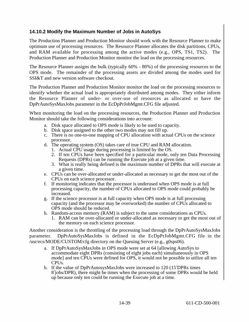
14.10.2 Modify the Maximum Number of Jobs in AutoSys
The Production Planner and Production Monitor should work with the Resource Planner to make optimum use of processing resources. The Resource Planner allocates the disk partitions, CPUs, and RAM available for processing among the active modes (e.g., OPS, TS1, TS2). The Production Planner and Production Monitor monitor the load on the processing resources.
The Resource Planner assigns the bulk (typically 60% - 80%) of the processing resources to the OPS mode. The remainder of the processing assets are divided among the modes used for SSI&T and new version software checkout.
The Production Planner and Production Monitor monitor the load on the processing resources to identify whether the actual load is appropriately distributed among modes. They either inform the Resource Planner of under- or over-use of resources as allocated or have the DpPrAutoSysMaxJobs parameter in the EcDpPrJobMgmt.CFG file adjusted.
When monitoring the load on the processing resources, the Production Planner and Production Monitor should take the following considerations into account:
a. Disk space allocated to OPS mode is likely to be used to capacity. b. Disk space assigned to the other two modes may not fill up. c. There is no one-to-one mapping of CPU allocation with actual CPUs on the science
processor. d. The operating system (OS) takes care of true CPU and RAM allocation.
1. Actual CPU usage during processing is limited by the OS. 2. If ten CPUs have been specified for a particular mode, only ten Data Processing
Requests (DPRs) can be running the Execute job at a given time. 3. What is really being defined is the maximum number of DPRs that will execute at
a given time. e. CPUs can be over-allocated or under-allocated as necessary to get the most out of the
CPUs on each science processor. f. If monitoring indicates that the processor is underused when OPS mode is at full
processing capacity, the number of CPUs allocated to OPS mode could probably be increased.
g. If the science processor is at full capacity when OPS mode is at full processing capacity (and the processor may be overworked) the number of CPUs allocated to OPS mode should be reduced.
h. Random-access memory (RAM) is subject to the same considerations as CPUs. 1. RAM can be over-allocated or under-allocated as necessary to get the most out of
the memory on each science processor.
Another consideration is the throttling of the processing load through the DpPrAutoSysMaxJobs parameter. DpPrAutoSysMaxJobs is defined in the EcDpPrJobMgmt.CFG file in the /usr/ecs/MODE/CUSTOM/cfg directory on the Queuing Server (e.g., g0sps06).
a. If DpPrAutoSysMaxJobs in OPS mode were set at 64 [allowing AutoSys to accommodate eight DPRs (consisting of eight jobs each) simultaneously in OPS mode] and ten CPUs were defined for OPS, it would not be possible to utilize all ten CPUs.
b. If the value of DpPrAutosysMaxJobs were increased to 120 (15 DPRs times 8 jobs/DPR), there might be times when the processing of some DPRs would be held up because only ten could be running the Execute job at a time.
14-39 611-CD-500-001

1. In such a case it might be possible to increase the number of CPUs allocated to the mode so that more than ten DPRs could be running the Execute job simultaneously.
Table 14.10-2 presents (in a condensed format) the steps required to modify the the maximum number of jobs in AutoSys. If you are already familiar with the procedures, you may prefer to use the quick-step table. If you are new to the system, or have not performed this task recently, you should use the following detailed procedures:
1 At the UNIX command line prompt enter:
cd /usr/ecs/<MODE>/CUSTOM/cfg a. The command shell prompt is displayed.
2 At the UNIX command line prompt enter:
vi EcDpPrJobMgmt.CFG a. The configuration file is displayed by the vi text editor.
3 Find DpPrAutosysMaxJobs= using vi commands.
4 Enter the desired maximum number of jobs in AutoSys in the specified mode. a. New number is entered.
5 Save the file.
6 Repeat Steps 1 through 5 as necessary to modify the values assigned to the DpPrAutoSysMaxJobs parameter in other modes.
Table 14.10-2. Modify the Maximum Number of Jobs in AutoSys - Quick-Step Procedures
Step What to Enter or Select Action to Take
1 Enter cd /usr/ecs/<MODE>/CUSTOM/cfg enter text, press Enter
2 Enter vi EcDpPrJobMgmt.CFGf enter text, press Enter
3 Find DpPrAutosysMaxJobs= enter text as necessary
4 Enter the desired maximum number of jobs in AutoSys in the specified mode
enter text as necessary
5 Save the file enter text as necessary
6 Repeat Steps 1 through 5 as necessary for other modes.
enter text as necessary
14-40 611-CD-500-001

15. Quality Assurance
This section describes the tools available for science data Quality Assurance (QA) - the QA Monitor and the QA Metadata Update Tool (QAMUT) .
Operational Quality Assurance is performed by DAAC operations personnel authorized to modify the value of the Operational QA flag attribute value for a product generated at the DAAC. The operator has the capability to view the product through EOSView and retrieve production history files. Figure 15-1 provides an overview of the quality assurance process.
(QA Monitor scenario)
1.
V0 Client SCF Access to ECS Holdings
(query, review, order). Additional
access to SDSRV metadata via
the Subscription GUI ; SCFs must **
Subscription Service
formulate requests to DAAC OPS.
2.SCF QA Updates
SCFs must coordinate QA metadata updates with DAAC OPS. There is no integrated tool with V0 Client.
3. DAAC OPS receive Update
**
QA Monitor
Notification
request and perform granule QA metadata updates to SDSRV.
DAAC OPS send confirmation 4. of update to SCFs.
** DAAC OPS Tool only.
(QAMUT scenario)
1. CLIENT
Results
SCF Access to ECS Holdings (query, review, order).
SCF reviews Results selects items for QA updating, and invokes QA MUT; Results
QA creates QA file for MUT access.
2.QA MUT
QA MUT Updates
QA MUT is initialized; user access is verified, results from client are loaded.
3. QA Updates are made and sent as a formatted request to the DAAC OPS (email).
DAAC OPS receives request 4.
DAAC OPS Updates
Notification
and performs updates to SDSRV.
5. DAAC OPS send confirmation
email of update to SCFs.
Figure 15-1. QA Metadata Update Process
15.1 QA Monitor
The purpose of the QA Monitor is to enable DAAC QA experts to modify ScienceQualityFlag and OperationalQualityFlag attributes of core metadata for a granule. SCFs send email requests to the
15-1 611-CD-500-001

DAAC to update the ScienceQualityFlag attribute, until the QA Metadata Update Tool (Section 15.2) is available.
The QA Monitor can be used to request the Science Data Server to search for specific types of Data Granules; Query, Retrieve, and Update (QRU) Metadata; transfer Data Granules to the operator’s computer; and transfer Production History to the operator’s computer. It can also be used to update data granule metadata, view graphical images of data granules, and print/display lists of data granules and data types. Table 15.1-1 summarizes common operator functions performed with the QA Monitor. Table 15.1-2 describes the fields in the QA Monitor; Table 15.1-2 provides the usage for each of the pushbuttons.
The QA Monitor is launched by clicking on the Desktop Icon, or via Unix commands. The Unix commands are provided following Tables 15.1-1 through 15.1-3.
Table 15.1-1. Common Operator Functions Performed with the QA Monitor
Operator Function Description Purpose
Query Data Granules Initiates a request to search the science archive for data granules
Find all archived data granules with the same data type which were inserted into the archive at a certain time (data interval)
Retrieve Data Granules Initiates a request to get data granules from the science archive
Transfer data granule(s) from archive to local disk for visualization
Visualize Data (HDF files) Display Visualize screen View graphical image of data granules to assess quality
Update Metadata Initiates a request to archive QA information about data granules
Update data granule QA information in the archive, based on DAAC QA activities encompassing use of the Visualize Data function.
Table 15.1-2. QA Monitor GUI FieldsÄField Name Data Type S i z e Entry Description
Data Granule Insert Begin End
Date min max
1/2/1901 6/1/2036
Initial default value can be changed by user
Search criteria for granule metadata beginning and end date
Data Types list single selection
N/A User selects a data type from the list displayed at startup
The list of all available data types at a specific DAAC
Data Granules list multiple selection
N/A User clicks data granule row(s) then clicks retrieve pushbutton
The list of all data granules in the date interval above for a particular selected data type are available for retrieval.
Status text N/A Displays status messages only
Displays status messages
15-2 611-CD-500-001

Table 15.1-3. QA Monitor GUI PushbuttonsÄButton Description
Query Populates list of data granules on the bottom half of the GUI for a particular selected data type within a data interval
Find (below the data types and data granules list) - allow the operator to perform a keyword search for information stored in those 2 lists.
Retrieve Allows the operator to retrieve data granule(s) or production history tar file(s) from the DAAC’s data archive and place on the local disk.
Update Pops up a Granule Parameters screen Update Metadata Dialog
Launching the QA Monitor Using UNIX Commands
1 Access the command shell. The command shell prompt is displayed.
NOTE: Commands in Steps 2 through 14 are typed at a UNIX system prompt.
2 Type xhost + then press the Return/Enter key on the keyboard.
3 Open another UNIX window.
4 Start the log-in to the Data Processing Subsystem host by typing either telnet hostname (e.g., g0sps06), rlogin hostname, or rsh hostname in the new window then press the Return/Enter key.
If you use the telnet command, a Login: prompt appears; continue with Step 5. If you use either the rlogin or rsh command, the system uses the User ID currently in use;
go to Step 6.
5 If a Login: prompt appears, log in as yourself by typing your UserID then pressing the Return/Enter key.
6 At the Password: prompt type your Password then press the Return/Enter key.
7 Start the log-in to DCE by typing dce_login then pressing the Return/Enter key.
8 At the Enter Principal Name: prompt type your DCE UserID then press the Return/Enter key.
9 At the Enter Password: prompt type your DCE Password then press the Return/Enter key.
1 0 Type setenv DISPLAY clientname:0.0 then press the Return/Enter key. Use either the terminal/workstation IP address or the machine-name for the clientname.
1 1 Type setenv MODE mode then press the Return/Enter key. The mode will most likely be one of the following operating modes:
OPS (for normal operation).
15-3 611-CD-500-001

TS1 (for SSI&T). TS2 (new version checkout).
Note that the separate subdirectories under /usr/ecs apply to (describe) different operating modes.
1 2 Type source /usr/ecs/mode/CUSTOM/utilities/EcCoEnvCsh then press Return/Enter. The source command sets the environment variables identified in the specified file.
1 3 Type cd /path then press Return/Enter. Change directory to the directory (e.g., /usr/ecs/mode/CUSTOM/utilities) containing the
data processing start scripts (e.g., EcDpPrStartQaMonitorGUI). 1 4 Type EcDpPrStartQaMonitorGUI mode ApplicationID & then press
Return/Enter to launch the QA Monitor GUI. The QA Monitor GUI (Figure 15-2) is displayed.
15-4 611-CD-500-001

Figure 15-2. QA Monitor GUI - QRU Data Tab
15.1.1 DAAC Product QA with the QA Monitor
The Product QA process begins with the QA Monitor Application. The DAAC operations personnel will Query, Retrieve, and Update (QRU) the selected product. The operator will then
15-5 611-CD-500-001

retrieve those specific products and perform a visual check of those products using the Visualize Data option of QA Monitor (Figure 15-3).
Retrieval and Viewing of Data Granules
1 Start up the QA Monitor
2 Select QRU Data tab.
3 From list of data types, select the ESDT or compose a query in query window and click on the Query button.
4 Select a data granule by filename from the list and click on the Retrieve Data Granule button. Quit the QA Monitor GUI.
5 To visualize the data, select the data granule as described above and click on the Visualize Data button. Displays EOS View GUI (Figure 15-3)
6 Open a HDF product file from which metadata is to be viewed, select the File→ Open button from the main menu bar. A File Selection Dialog window will open and the user should be able to select the
appropriate directory and file to open. Once the desired product file has been opened, the specific types of HDF objects in the file
will be listed in the Contents window.
7 From the Contents window double-click on a particular HDF Object (Vgroup, SDS, etc.). The structure of the HDF object will appear in a dialog window with buttons on the bottom
portion of the window to view the data of the object itself.
8 Display the science data values of this particular HDF object by selecting the Table button to display the table data of the object.
9 View the attribute values of this particular HDF object by selecting the File-Attribute button. Metadata is referred to as attribute data. Any metadata associated with the object will be displayed in another text window.
1 0 Quit when done by typing Q then press the Enter key.
15-6 611-CD-500-001

Visualize Data
Figure 15-3. QA Monitor - Visualize Data
15.1.2 Updating QA Metadata
After the viewing, the operator will update the Operational QA flag for that specific product. The operator also updates the Science QA flags in response to an email request from SCF personnel, who have the responsibility for performing QA of their own products. This procedure for updating QA metadata starts with the assumption that all applicable servers are currently running and the QA Monitor GUI QRU data tab (Figure 15-4) is being displayed.
Table 15.1-4 summarizes the QA metadata attributes and their descriptions.
15-7 611-CD-500-001

Table 15.1-4. QA Metadata Attributes Field Name Data Type Description
OperationalQualityFlag
ScienceQualityFlag
character DAAC and SCF quality status setting of a data granule parameter, selected by the user. The valid values are: - passed - failed - being investigated - not investigated - inferred passed - inferred failed
OperationalQualityFlagExplanation
ScienceQualityFlagExplanation
character Text describing quality status (less than 255 characters), input by user.
AutomaticQualityFlag character DAAC and SCF quality status setting of a data granule parameter, set during data processing.
AutomaticQualityFlagExplanation character Text describing quality status of a data qranule parameter - set during data processing.
Updating Quality Assurance (QA) Metadata using the QA Monitor
1 In the Data Types field, click on the data type to be checked. It may be necessary to scroll through the Data Types list. The selected data type is highlighted. Only one data type can be selected at a time. Alternatively, the Find field and button can be used for specifying a data type.
The Find field is case-sensitive. 2 Click in the appropriate Data Granule Insert window field(s) and either type or use the
up/down arrow buttons to enter the Begin date and End date in MM/DD/YYYY format. In the Data Granule Insert window it is necessary to specify the range of dates
(between the Begin date and the End date) to formulate a query for searching for the desired granule(s) to be checked. Time is based upon day of insert into the data server. If no dates are entered, an error message is displayed. The up and down arrows next to the duration fields may be used for modifying entries in each field.
The Tab key may be used to move from field to field. 3 Click on the Query button.
Granules within the specified date range appear in the Data Granules field. 4 In the Data Granules field, click on the granule for which metadata is to be updated.
It may be necessary to scroll through the list of granules. The selected granule is highlighted. Alternatively, the Find field and button may be used for specifying a data granule.
The Find field is case-sensitive. 5 Click on the Update Metadata button.
The Update Metadata window is displayed. The Update Metadata window displays one line for each parameter for the selected granule.
6 Click on a parameter in the Update Metadata window. The selected parameter is highlighted.
15-8 611-CD-500-001

The Edit Parameter dialog box is displayed. 7 Click and hold on the Operator Quality Flag option button, move the mouse cursor to
the desired selection (highlighting it), then release the mouse button. The selected metadata flag is displayed on the Operator Quality Flag option button. The following options are available:
passed failed being investigated not investigated inferred passed inferred failed
8 Type an explanation for changing the QA flag value in the Explanation field. 9 Click and hold on the SCF Quality Flag option button, move the mouse cursor to the
desired selection (highlighting it), then release the mouse button.The selected metadata flag is displayed on the SCF Quality Flag option button.The same options are available as those on the Operator Quality Flag option button.
1 0 Type an explanation of the QA flag selection in the Explanation field. 1 1 Click on the OK button to accept the QA flag settings.
The Edit Parameter dialog box is dismissed. 1 2 To verify that the QA flag settings have actually been applied to the granule, first repeat
Steps 1 through 5 to retrieve the same granule. The Granule Parameters window (Figure 15-4) is displayed. The QA flag values and explanations entered using the Edit Parameter dialog box are
displayed. 1 3 Repeat steps as necessary to review additional granules.
15-9 611-CD-500-001

Figure 15-4. QA Monitor Granule Parameters Window
15.1.3 Production History
The Production History (PH) is created during PGE execution within the PDPS and then Inserted into the Data Server upon PGE completion. Included in the PH are the PGE log files. Accessing a Production History associated with a particular PGE run requires the DPR ID of the PGE run.
The Production History is retrieved using the QA Monitor GUI, using the following procedure.
Follow the procedures above for selecting a data granule.
• Select the Retrieve ProdHistory button and view the contents of the Production History Log.
15.2 QA Metadata Update Tool
The purpose of the QA Metadata Update Tool (QAMUT) is to enable Science Computing Facility (SCF) and Distributed Active Archive Center (DAAC) QA experts to modify values of their respective quality flags (i.e., ScienceQualityFlag and OperationalQualityFlag) on core metadata, provided via a client, for multiple granules at a time in a batch mode (vs. one granule at a time
15-10 611-CD-500-001

using the QA Monitor). At the time of this writing, each DAAC plans to utilize either an existing client at the DAAC or develop a client to search the metadata holdings at the DAAC. It is anticipated that DAACs will integrate the client with QAMUT software developed by the ECS project and provided to DAACs. The integrated client and QAMUT software will provide complete tools to perform quality assurance updates on metadata. The detailed implementation plans for QAMUT at the DAACs, if any, are not known at this time.
The QAMUT tool itself consists of two major components: The SCF component (for updating ScienceQualityFlags) and the DAAC component (for updating OperationalQualityFlags). The QAMUT is fully documented in the following white paper: QA Metadata Update Tool for the ECS Project, April 1998 (160-WP-002-001).
15-11 611-CD-500-001

This page intentionally left blank.
15-12 611-CD-500-001

16. Ingest
This section describes the procedures the Data Ingest Technician (DIT) can use when performing and monitoring ingest of science data. The data ingest process is largely automated, however, the DIT will be required to support hard media operations, resolve problems, periodically monitor ingest operations, and coordinate with the appropriate internal and external entities to resolve resource conflicts. Section 16.1 describes the Ingest subsystem custom software items. Section 16.2 describes how to use the ECS GUI Ingest tool. Section 16.3 describes how to use the HTML Interactive Ingest tool. Section 16.4 describes the Ingest Polling process. Section 16.5 describes the process of recovering from Data Ingest Failures. Section 16.6 describes the Document Ingest process. Section 16.7 describes how to use the ECS Science Data Server Operator tool.
16.1 Ingest Custom Software Items
The Ingest custom software items supports the ingest of data into ECS repositories on a routine and ad hoc basis. The software supports a variety of data formats and structures. Ingest data processing and storage functions vary according to attributes of the ingested data such as data type, data format, and the level to which the ingested data has been processed.
The Ingest subsystem is capable of accepting data from a variety of sources including both electronic network interfaces and physical media. Data received is predefined within ECS with regard to expected metadata and metadata characteristics, data types, files, and formats, and means of delivery to ECS in accordance with approved ICDs with external organizations. The following list defines the ECS Ingest Subsystem custom software items:
1. EcInAuto - is the Automated Network Ingest Interface process that provides basic capability to ingest data electronically from an external source.
2. EcInPolling - is the Polling Ingest Client Interface process that creates polling request, detects new files in a specified external location, creates and submits ingest request.
3. EcInInter - is the Interactive Ingest Interface process that provides science users and ECS operators the capability for interactive request to ingest data available on the network.
4. EcInReqMgr - is the Ingest Request Manager process that manages ingest request traffic and processing.
5. EcInGran - is the Ingest Granule Server process that provides services for required preprocessing of data and subsequent insertion into the FSMS.
6. EcInGUI - is Ingest GUI Interface process that provides operators ability to perform ingest from physical media, monitor the status of on-going ingest requests, and modify Ingest configuration parameters.
16-1 611-CD-500-001

1
2
3
4
5
6
7. Ingest Database - is a Sybase database that stores and provides access to Ingest Subsystem internal data.
16.2 ECS Ingest Tool
The ECS Ingest tool has five tab widgets; Ingest Intro, History Log, Monitor/Control, Operator Tools, and Media Ingest. The Ingest Intro screen can be used as a menu path to Save or Print screens, and Exit the Ingest tool. The History Log (Section 16.2.2 & Section 16.2.3) is a view only screen which allows the DIT the capability to view ingest activities that have already completed, and to create reports. The Monitor/Control (Section 16.2.4) screen provides the DIT the capability to view and update ongoing ingest activities in the system. The Operator Tools (Section 16.2.5) are used by the DIT to view and set ingest thresholds. The Media Ingest (Section 16.2.6) screen gives the DIT the capabilities to perform media ingest.
The Activity Checklist table that follows provides an overview of the Ingest tool and its functions. Column one (Order) shows the order in which tasks should be accomplished. Column two (Role) list the Role/Manager/Operator responsible for performing the task. Column three (Task) provides a brief explanation of the task. Column four (Section) provides the Procedure (P) section number or Instruction (I) section number where details for performing the task can be found.
Table 16.2-1. ECS Ingest Tool - Activity Checklist Order Role Task Section
DIT Starting the Ingest GUI (P)16.2.1
DIT Viewing the Ingest History Log (P)16.2.2
DIT Ingest History Log Reports (P)16.2.3
DIT Monitoring/Controlling Ingest Requests (P)16.2.4
DIT Suspending Ingest Requests (P)16.2.5
DIT Resuming Ingest Requests (P)16.2.6
5 DIT Ingest Operator Tools (P)16.2.7
6 DIT Physical Media Ingest (P)16.2.8
16.2.1 Starting the Ingest GUI
Starting the Ingest GUI in normally operations will be just a matter of clicking an icon that appears on your desktop. Because the desktop configurations have not been installed to date it will be necessary to follow the interim procedure described below. Starting the Ingest GUI assumes that the applicable servers are running and the DIT has logged in. If you are already familiar with the procedure, you may prefer to use the quick-step table at the end of the procedure. If you are new to the system, you should use the following detailed procedures:
1 Type xhost + at the command shell prompt and then press Return.
16-2 611-CD-500-001

1
2
3
4
5
6
7
8
2 Bring up the Ingest GUI server. If the Ingest GUI has not already been brought up. From a SUN workstation or NCD X-Term terminal telnet into the Ingest Server. Enter telnet <hostname>. Example telnet g0dis01.
3 Log into the Ingest Operator workstation using your user identifier and password by typing YourUserID, and then press Return. • A password prompt is displayed.
4 Enter YourPassword, then press Return. • You are authenticated as yourself.
5 Set your terminal display environment using the following command: setenv DISPLAY <hostname:0.0>
6 Create an xterm window for the Ingest GUI Ingest the following command: xterm -n GUI_<mode> -sl 5000-sb &
7 Change directory to the directory containing the Ingest GUI command file: cd /usr/ecs/<mode>/CUSTOM/utilities
8 Start the Ingest GUI using the following command: EcInGuiStart <mode> • The ECS Ingest tool is opened. • The Ingest Intro screen is displayed.
Table 16.2-2. Starting Ingest Operator GUI - Quick-Steps S t e p What to Enter or Select Action to Take
xhost + press Return
telnet <hostname> press Return
YourUserID press Return
YourPassword press Return
setenv DISPLAY <hostname:0.0> press Return
xterm -n GUI_<mode> -sl 5000-sb & press Return
cd /usr/ecs/<mode>/CUSTOM/utilities press Return
EcInGuiStart <mode> press Return
16.2.2 Viewing the Ingest History Log
The DIT can determine if an Ingest request has been completed by viewing the entries in the ECS Ingest History Log. An Ingest request is not logged into the History Log until the Ingest process has been completed. There are four different search criteria that can be used to view Ingest History Log entries, the Start and Stop Date/Time, the Data Provider ID, the Data Type, and Final Request Status. The DIT must manually enter the Start and Stop Date/Time criteria, which displays all Ingest entries that were logged between the start date and time, and the stop date and time. The Data Provider, Data Type, and Final Request Status each have a drop down option menu in which to select the criteria. After the DIT enters
16-3 611-CD-500-001

the search criteria, he/she clicks on the Display button to display the log of completed Ingest entries that match the search criteria. The History Log displays the following:
Request ID Data Provider, Status, Ingest Type, Start Date, Start Time, End Date, End Time, Total Number of Granules, #Success Granules, Data Vol (MB), File Count, Time to Xfer (min.), Time Preproc (min.), Time to Archive (min.), and Priority Restart Flag.
The DIT can display the same information on the granule level by clicking on the desired entry.
The procedure that follows explains how to view Ingest Log entries using the History Log. This example will use the Start and Stop date/time filters to display a list of Ingest requests that were logged in the last twenty-four hour period. If you are already familiar with the procedure, you may prefer to use the quick-step table at the end of the procedure. If you are new to the system, you should use the following detailed procedures:
1 Click on the ECS Ingest icon. This assumes that the Ingest GUI is running, if the GUI is not up, then follow the steps for bringing up the Ingest GUI outlined in section 16.2.1. • The ECS Ingest tool is opened. • The Ingest Intro screen is displayed.
2 Click the History Log tab widget. • The History Log screen is displayed.
3 Click on the Start Date/Time field. • The cursor moves to the month field.
4 Enter the month, then press Tab. • The cursor moves to the day field.
5 Enter the day of the month, then press Tab. • The cursor moves to the year field.
6 Enter the year, then press Tab. • The cursor moves to the hour field.
7 Enter the hour, then press Tab. • The cursor moves to the min field.
8 Enter the minute, then press Tab. • The cursor moves to the sec field.
9 Enter the seconds, then press Tab or, bypass the second’s field by pressing tab first. • The cursor moves to the month field for Stop Date/Time.
1 0 Repeat steps 4 through 9 for the Stop Date/Time field.
1 1 Select either Detailed Report or Summary Report. • Summary Report requires the operator to select either Request Level or Granule
level.
1 2 Click on the Display button.
16-4 611-CD-500-001

1
2
3
4
5
6
7
8
9
1 0
1 1
1 2
1 3
1 4
1 5
1 6
1 7
1 8
1 9
2 0
• Each ingest request that was completed and logged between the start and end time and date are displayed.
• Each entry displays the Request ID, # of Success Granules, External Data Provider, Ingest Type, Processing Start and End Time, Data Volume, Number of Data Sets, and Number of Data Files.
1 3 Click on an individual Entry. • The granule level of the selected entry is displayed.
1 4 Select another function by clicking on a GUI tab.
1 5 To exit the ECS Ingest tool, select menu path File/Exit.
Table 16.2-3. View Ingest History Log - Quick-Steps S t e p What to Enter or Select Action to take
ECS Ingest icon single Click
History Log press Return
Month (Start Month field) single Click
Enter the Month press Tab
Enter the Day press Tab
Enter the Year press Tab
Enter the Hour press Tab
Enter the Minute press Tab
Enter the Seconds press Tab
Enter the Month press Tab
Enter the Day press Tab
Enter the Year press Tab
Enter the Hour press Tab
Enter the Minute press Tab
Enter the Seconds press Tab
Select Detailed Report or Summary Report single Click
Display button single Click
Individual Entry record single Click
Select another function single Click or,
File/Exit single Click and drag
16.2.3 Ingest History Log Reports
The History Log can support four report formats, a request history log report, a data type history report, a request summary statistics report, and a data type summary statistics report. The reports can be generated for specified time periods and executed on a regular basis. There are two radio buttons above the display box, Detailed Report and Summary Report. Each report supplies the DIT and operations staff with a view of the ingest request completion performance.
16-5 611-CD-500-001

The Detailed Report gives detailed information about each completed ingest request. The Summary Report gives a summary, which includes the average and maximum time taken to perform each step in the ingest process.
The Detailed Report can be sorted by Start and Stop Date & Time, by Data Provider, and by Data Type. The default for the Detailed Report is DAAC and Start Time. The Summary Report should be sorted by DAAC, Data Provider or Data Types.
The following procedure will order a Detailed Report with the Data Provider as the sort criteria, then will clear the screen and order a Summary Report using the Data Type as the sort criteria. If you are already familiar with the procedure, you may prefer to use the quick-step table at the end of the procedure. If you are new to the system, you should use the following detailed procedures:
1 Click on the ECS Ingest icon. This assumes that the Ingest GUI is running, if the GUI is not up, then follow the steps for bringing up the Ingest GUI outlined in section 16.2.1. • The ECS Ingest tool is opened. • The Ingest intro screen is displayed.
2 Click on the History Log tab widget. • The History Log screen is displayed.
3 Click on the Data Provider field. • Cursor moves to the Data Provider field.
4 Enter the Data Provider, then press Tab or, a drop down option menu may also be used as follows: a) Point the mouse on the arrow to the right of the Data Provider field. b) While holding down on the mouse, highlight the required Data Provider. c) Release the mouse button. d) The Data Provider that was chosen is now displayed in the Data Provider field.
5 Click on the Detailed Report Radio box.
6 Click on the Display button. • The Detailed Report is now displayed. • The Detailed Report displays the following information; Request ID, Data
Provider, Start and End Time, Completion Status, Restart Flag, Processing Time (minutes),Transfer Time (minutes), Archive Time (minutes), Number of Files, Number of Granules, Number of Success Granules, Data volume (MB), and Ingest Type.
7 Click on the Clear All button. • The display box and criteria fields are cleared.
8 Click on the Data Type field. • The cursor moves to the Data Type field.
9 Enter the Data Type, then press Tab or, a drop down option menu may also be used as shown below: a) Point the mouse on the arrow to the right of the Data Type field.
16-6 611-CD-500-001

1
2
3
4
5
6
7
8
9
1 0
1 1
1 2
1 3
1 4
b) While holding down on the mouse, highlight the required Data Type. c) Release the mouse button. The Data Type that was chosen is now displayed in the
Data Type field.
1 0 Click on the Summary Report radio box.
1 1 Click on the Display button. • The Summary Report is displayed. • The Summary Report displays the following information; Data Provider, Data
Type, Total Requests, Total Errors, Granules (Avg/Max), Files (Avg/Max), Size -MB (Avg/Max), Transfer Time- minutes (Avg/Max), Pre-Processing Time-minutes (Avg/Max), and Archive Time-minutes (Avg/Max).
1 2 Print the report by following menu path File / Print.
1 3 Select another function by clicking on a widget tab.
1 4 To exit the ECS Ingest tool, select menu path File / Exit.
Table 16.2-4. Ingest History Log Reports - Quick-Steps S t e p What to Enter or Select Action to Take
ECS Ingest icon single Click
History Log press Return
Data Provider field single Click
Enter the Data Provider press Tab
Detailed Report Radio Box single Click
Display button single Click
Clear All button single Click
Data Type field single Click
Enter Data Type press Tab
Summary Report Radio Box single Click
Display button single Click
File / Print single Click and drag
Select another function single Click or,
File/Exit single Click and drag
16.2.4 Monitoring/Controlling Ingest Requests
The DIT can monitor and control ingest activities using the Ingest Monitor/Control tool. The DIT can view all or selective ingest requests in the system. A search can be filtered by using a sort criteria of Request ID, Data Provider, or All Requests. After the search criteria has been selected, the DIT has the option of displaying a Graphical View or a Text View of the ingest requests. The Graphical View displays the Request Id, the Time processing began, and the Percent of the ingest process that has been completed. The Text View displays the Request Id,
16-7 611-CD-500-001
State of Request, External Data Provider, Ingest Type, Request Priority, Start Date & Time, Expiration Date, Total Granules, and Completion Time.
The DIT has the capability of updating ongoing ingest activities in the system. The DIT can Suspend, Resume, Cancel, and change the Priority of a request. To display a request on a granule level, the DIT will double click on the request.
The following procedure will display all requests currently in the system, select and view a request on the granule level, then cancel the request. If you are already familiar with the procedures, you may prefer to use the quick-step tables at the end of this procedure. If you are new to the system, or have not performed this task recently, you should use the detailed procedures that follow.
1 Click on the ECS Ingest icon. This assumes that the Ingest GUI is running, if the GUI is not up, then follow the steps for bringing up the Ingest GUI outlined in section 16.2.1. • The ECS Ingest tool is now open. • The Ingest Intro screen is displayed.
2 Click on the Monitor/Control tab widget. • The Monitor/Control screen is displayed.
3 Click on the All Requests button, in the radio box.
4 Click on the Text View button. • All ongoing ingest requests are displayed.
5 Highlight individual account, then double Click • Text is displayed at the granule level.
6 Highlight the request that needs to be canceled, then single Click.
7 Click on the Cancel button, from the toggle control box.
8 Click on the OK push button. • Activates the toggle push buttons. • A confirmation dialog box pops up.
9 Click the OK button in the confirmation dialog box. • Ingest request has been canceled.
1 0 Select another function by clicking on a widget tab.
1 1 To exit the ECS Ingest tool, select menu path File / Exit.
16-8 611-CD-500-001
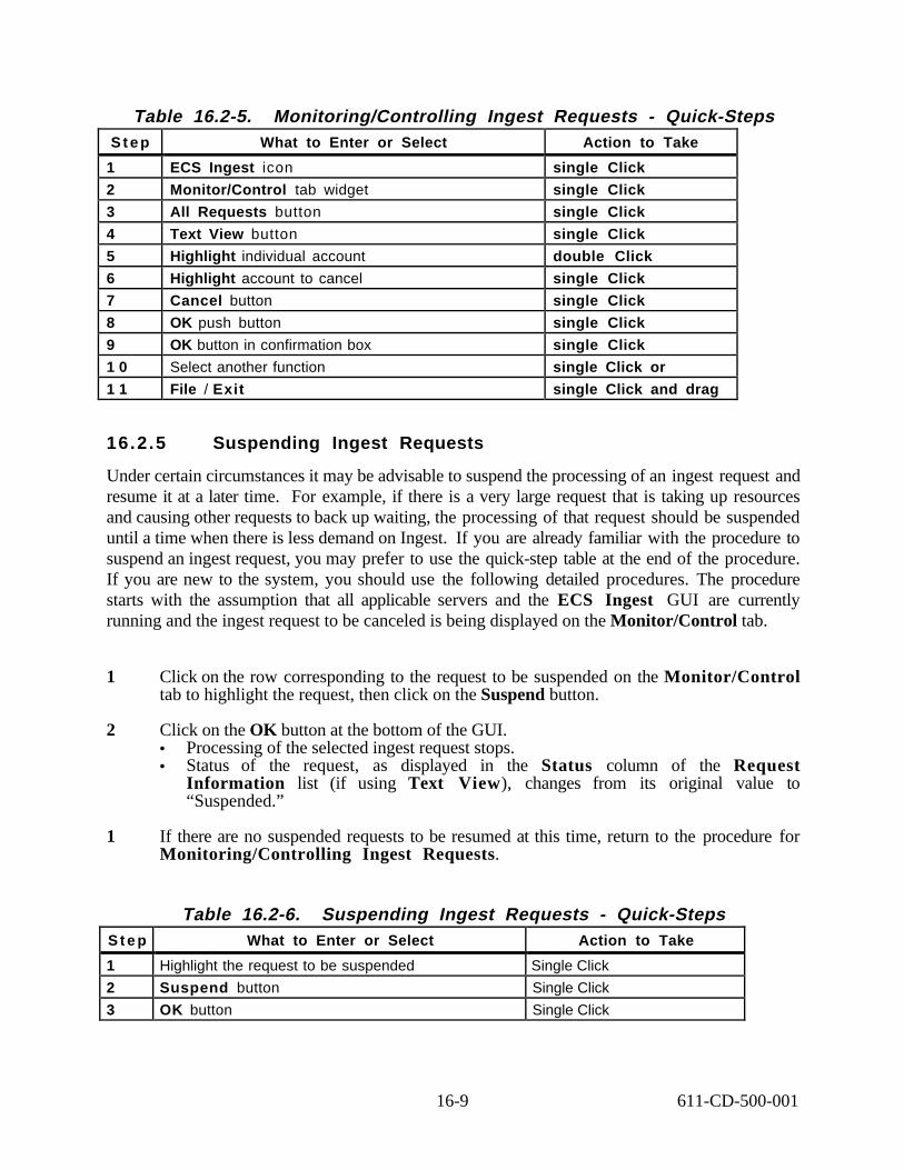
1
2
3
4
5
6
7
8
9
1 0
Table 16.2-5. Monitoring/Controlling Ingest Requests - Quick-Steps S t e p What to Enter or Select Action to Take
ECS Ingest icon single Click
Monitor/Control tab widget single Click
All Requests button single Click
Text View button single Click
Highlight individual account double Click
Highlight account to cancel single Click
Cancel button single Click
OK push button single Click
OK button in confirmation box single Click
Select another function single Click or
1 1 File / Exit single Click and drag
16.2.5 Suspending Ingest Requests
Under certain circumstances it may be advisable to suspend the processing of an ingest request and resume it at a later time. For example, if there is a very large request that is taking up resources and causing other requests to back up waiting, the processing of that request should be suspended until a time when there is less demand on Ingest. If you are already familiar with the procedure to suspend an ingest request, you may prefer to use the quick-step table at the end of the procedure. If you are new to the system, you should use the following detailed procedures. The procedure starts with the assumption that all applicable servers and the ECS Ingest GUI are currently running and the ingest request to be canceled is being displayed on the Monitor/Control tab.
1 Click on the row corresponding to the request to be suspended on the Monitor/Control tab to highlight the request, then click on the Suspend button.
2 Click on the OK button at the bottom of the GUI. • Processing of the selected ingest request stops. • Status of the request, as displayed in the Status column of the Request
Information list (if using Text View), changes from its original value to “Suspended.”
1 If there are no suspended requests to be resumed at this time, return to the procedure for Monitoring/Controlling Ingest Requests.
Table 16.2-6. Suspending Ingest Requests - Quick-Steps S t e p What to Enter or Select Action to Take
1 Highlight the request to be suspended Single Click
2 Suspend button Single Click
3 K button Single Click O
16-9 611-CD-500-001

16.2.6 Resuming Ingest Requests
After the matter that caused an ingest request to be suspended from processing has been taken care of, the processing can be resumed. If you are already familiar with the procedure to resume an ingest request, you may prefer to use the quick-step table at the end of the procedure. If you are new to the system, you should use the following detailed procedures. The procedure starts with the assumption that all applicable servers and the ECS Ingest GUI are currently running and the ingest request to be canceled is being displayed on the Monitor/Control tab.
1 Click on the row corresponding to the request to be resumed on the Monitor/Control tab, then click on the Resume button.
2 Click on the OK button at the bottom of the GUI. • The selected ingest request resumes processing. • Status of the request, as displayed in the Status column of the Request
Information list (if using Text View), changes from “Suspended” to whatever state is appropriate for the continuation of request processing (depending on its status when it was suspended).
3 Return to the procedure for Monitoring/Controlling Ingest Requests.
Table 16.2-7. Resuming Ingest Requests - Quick-Steps S t e p What to Enter or Select Action to Take
1 Highlight the request to be resumed Single Click
2 Resume button Single Click
3 OK button Single Click
16.2.7 Ingest Operator Tools
The Ingest Operator Tools give the Production Monitor (PM) and/or DIT the capability to set and view ingest thresholds. The ingest thresholds are broken up into two groups: System-wide and Data Provider specific. To edit the Data Provider click on the Modify External Data Provider/User Information button in the Radio box just below the tab widgets (Section 16.2.7.1). To make System-Wide edits click on the Modify System Parameters (Section 16.2.7.2). When a DIT reviews the previous day’s Ingest activity, he/she may discover that there is a backlog of requests for ingest. After reviewing the report he/she may invoke the Ingest Operator Tool, then increase the System or Data Provider volume threshold to support a catchup mode. Another tool, File Transfer (Section 16.2.7.3), allows the DIT to transfer requested files to optional remote sites.
The Activity Checklist table that follows provides an overview of the Ingest Operator tool. Column one (Order) shows the order in which tasks should be accomplished. Column two (Role) list the Role/Manager/Operator responsible for performing the task. Column three (Task) provides
16-10 611-CD-500-001

a brief explanation of the task. Column four (Section) provides the Procedure (P) section number or Instruction (I) section number where details for performing the task can be found.
Table 16.2-8. Ingest Operator Tools - Activity Checklist Order Role Task Section
1 PM/DIT Modify External Data Provider/User Information
(P) 16.2.7.1
2 PM/DIT Modify System Parameters (P) 16.2.7.2
3 DIT File Transfer (P) 16.2.7.3
16.2.7.1 Modify External Data Provider/Interactive User Information
The PM or DIT can edit the FTP User Name, FTP Password, Email Address, HTML Password, CDS Entry Name, Server Destination UUID, Volume Threshold, Request Threshold, and Priority Level when the Modify External Data Provider/Interactive User Information toggle button is selected.
The Volume Threshold is the maximum data volume allowed to be ingested concurrently by the data provider in one day. The Request Threshold is the maximum number of requests allowed to be processed by the data provider in one day. One day is a 24 hour period beginning when the first request is received. Each Data Provider is given a data Priority Level, which can effect when the ingest data is processed. When the Data Providers thresholds have been reached, the system will no longer process ingest requests for that specific Data Provider until the following day. If the DIT determine that this specific Data Provider’s data needs to be processed, he/she can change the thresholds to allow the system to accept the request.
The procedure that follows explains how to edit the Data Provider’s Email Address, Volume Threshold, Request Threshold and Priority Level. If you are already familiar with the procedures, you may prefer to use the quick-step table at the end of this procedure. If you are new to the system, or have not performed this task recently, you should use the following detailed procedure.
1 Click on the ECS Ingest icon. This assumes that the Ingest GUI is running, if the GUI is not up, then follow the steps for bringing up the Ingest GUI outlined in section 16.2.1. • The ECS Ingest tool is opened. • The Ingest Info screen is displayed.
2 Click on the Operator Tools tab widget. • The Operator Tool is opened.
3 Click on the Modify External Data Provider/User Information toggle tab. • The Data Provider screen is displayed.
4 Click on the Data Provider field. • Cursor moves to the Data Provider field.
16-11 611-CD-500-001

5 Enter the Data Provider name, then press Tab or, a drop down option menu may also be used as follows: a) Point the mouse on the arrow to the right of the Data Provider field. b) While holding down the mouse, highlight the chosen Data Provider. c) Release the mouse button. The Data Provider that was chosen is now displayed
in the Data Provider field.
6 Click on the Email Address field. • Cursor moves to the Email Address field.
7 Enter the Email Address, then press Tab. • Cursor moves to the new Volume Threshold field.
8 Enter the New Volume Threshold, then press Tab. • Cursor moves to the new Request Threshold field.
9 Enter the New Request Threshold, then press Tab. • Cursor moves the new Priority Level field.
1 0 Enter the new Priority Level, then press Tab or, a drop down option menu may also be used as follows: a) Point the mouse on the arrow to the right of the New Priority Level field. b) While holding down the mouse, highlight the chosen Priority Level. c) Release the mouse button. The Priority Level that was chosen is now displayed
in the Priority Level field.
1 1 Click on the OK push button. • Invokes changes to the system.
1 2 Select another function by clicking on a widget tab.
1 3 To exit the ECS Ingest tool, select menu path File / Exit.
16-12 611-CD-500-001

Table 16.2-9. Modify External Data Provider/ Interactive User Information - Quick-Steps
S t e p What to Enter or Select Action to Take
1 ECS Ingest icon Single Click
2 Operator Tools Tab widget Single Click
3 Modify External Data Provider/Interactive User Information toggle tab
Single Click
4 Data Provider field Single Click
5 Enter the Data Provider Name Press Tab
6 Email Address field Single Click
7 Enter the Email Address Press Tab
8 Enter the New Volume Threshold Press Tab
9 Enter the New Request Threshold Press Tab
1 0 Enter the New Priority Level Press Tab
1 1 OK push button Single Click
1 2 Select another function/widget Single Click
1 3 File / Exit Single Click and drag
16.2.7.2 Modify System Parameters
The Modify System Parameters tool allows the PM or DIT to edit the System Volume Threshold, to set the maximum number of ingest requests allowed to be processed concurrently, the maximum data volume to be ingested concurrently, the number of transfer retry attempts to make when network failure occurs, and the Polling timer indicating how long to wait before starting the Ingest Polling.
In the following procedure the DIT will invoke the ECS Ingest tool then select the Operator Tools tab widget. From the Operator Tools display screen the DIT will click on the Modify System Parameters toggle button, then edit the Volume Threshold, Request Threshold, Communication Retry Count, Communication Retry Interval, Monitor Time, and Screen Update Time fields. If you are already familiar with the procedure, you may prefer to use the quick-step table at the end of the procedure. If you are new to the system, or have not performed this task recently you should use the following detailed procedure.
1 Click on the ECS Ingest icon. This assumes that the Ingest GUI is running, if the GUI is not up, then follow the steps for bringing up the Ingest GUI outlined in section 16.2.1. • The ECS Ingest tool is opened. • The Ingest Intro screen is displayed.
2 Click on the Operator Tools tab widget. • The Operator Tool is opened.
3 Click on the Modify System Parameters toggle tab. • The System Parameters screen is displayed.
16-13 611-CD-500-001
4 Click on the New Volume Threshold field. • The cursor moves to the New Volume Threshold field.
5 Enter the New Volume Threshold, then press Tab. • The Maximum data volume to be ingested concurrently is changed. • The cursor moves to the New Request Threshold field.
6 Enter the New Request Threshold, then press Tab. • The Maximum number of ingest requests to be processed concurrently is changed. • The cursor moves to the New Communication Retry Count field.
7 Enter the New Communication Retry Count, then press Tab. • The number of retries to perform when a communication failure is encountered with
the external data provider is changed. • The cursor moves to the New Communication Retry Interval field.
8 Enter the New Communication Retry Interval, then press Tab. • The number of minutes to wait between retries when attempting to communicate with
the External Data Provider. • The cursor moves to the Monitor Time field.
9 Enter the New Monitor Time, then press Tab. • The Monitor Time tells the system how often to monitor the network for ingest
requests. • The cursor moves to the Screen Update Time field.
1 0 Enter the New Screen Update Time, then press Tab. • The Screen Update Time tells the system how often to update the
Monitor/Control screen, which shows the current ingest request activity.
1 1 Click on the OK push button. • Implements the changes entered.
1 2 Select another function by clicking on a widget tab.
1 3 To exit the ECS Ingest tool, select menu path File / Exit.
16-14 611-CD-500-001

1
2
3
4
5
6
7
8
9
1 0
1 1
1 2
1 3
Table 16.2-10. Modify System Parameters - Quick-Step Procedures S t e p What to Enter or Select Action to Take
ECS Ingest icon Single Click
Operator Tools Tab widget Single Click
Modify System Parameters toggle tab Single Click
New Volume Threshold Single Click
Enter the New Volume Threshold Press Tab
Enter the New Request Threshold Press Tab
Enter the New Communication Retry Count Press Tab
Enter the New Communication Retry Interval Press Tab
Enter the New Monitor Time Press Tab
Enter the New Screen Update Time Press Tab
OK push button Single Click
Select another function/widget Single Click
File / Exit Single Click and drag
16.2.7.3 File Transfer
The File Transfer tool allows the DIT to transfer System Management Center (SMC) History and Generic files to the Science Community. The tool allows the DIT to build a SMC History File or select any file to be transferred from a specified source of origin to a destination desired by the user.
In the following procedure the DIT will invoke the ECS Ingest tool then select the Operator Tools tab widget. From the Operator Tools display screen the DIT will click on the File Transfer tab, then edit the Volume Threshold, Request Threshold, Communication Retry Count, Communication Retry Interval, Monitor Time, and Screen Update Time fields. If you are already familiar with the procedure, you may prefer to use the quick-step table at the end of the procedure. If you are new to the system, or have not performed this task recently you should use the following detailed procedure.
1 Click on the ECS Ingest icon. This assumes that the Ingest GUI is running, if the GUI is not up, then follow the steps for bringing up the Ingest GUI outlined in Section 16.2.1. • The ECS Ingest tool is opened. • The Ingest Intro screen is displayed.
2 Click on the Operator Tools tab widget. • The Operator Tool is opened.
3 Click on the File Transfer tab. • The File Transfer screen is displayed.
4 Click on Build SMC History File or the Generic File Transfer push button. • The Build SMC History File creates selected file for operator transfer. • The Generic File transfer allows any directory or file to be transferred.
16-15 611-CD-500-001

5 Click on the New Filter field. • The Cursor moves enters the field.
6 Enter the New Filter, then press Tab. • The Cursor moves to Directories field.
7 At Directories, select desired table entry, then press Tab. • The directory is entered into the Selection field. • The Cursor moves to Files field.
8 At Files, select desired table entry, then press Tab. • The file is added to the path entered in the Selection field. • The Cursor moves to Selection field.
9 Click on the OK push Button in the Transfer Origin Box.
1 0 Enter the New Transfer Destination in the Transfer Destination field.
1 1 Click on the OK push button for File Transfers window.
1 2 Select another function by clicking on a widget tab.
1 3 To exit the ECS Ingest tool, select menu path File / Exit.
Table 16.2-11. File Transfer- Quick-Step Procedures S t e p What to Enter or Select Action to Take
1 ECS Ingest icon single Click
2 Operator Tools Tab widget single Click
3 File Transfer toggle tab single Click
4 Click SMC Build History File or Generic File Transfer single click
6 Click the New Filter, enter filter press Tab
7 Enter the New Directories press Tab
8 Enter the New Files press Tab
9 OK push button in Transfer Origin press Tab
1 0 Enter the New Transfer Destination press Tab
1 1 OK push button for window single Click
1 2 Select another function/widget single Click
1 3 File/Exit single Click and drag
16.2.8 Physical Media Ingest
When the Science Community sends a data ingest request, the DIT can ingest data from physical media into the DAAC using the Media Ingest tool. Table 16.2-12 identifies the different types of physical media used within the ECS system ingest process. Each cartridge is identified by means of a bar code label that shows the media number.
16-16 611-CD-500-001

Table 16.2-12. Physical Media Ingest Types Media Type Media Name Media Purpose Capacity
4mm 4 Millimeter cartridges Ingest 120m 4Gb
8mm 8 Millimeter cartridges Ingest 160m 7Gb
9 track 9 Track magnetic tape Ingest 6.2 kb per inch
D3 D3 Cartridge tape Ingest (EDC Only) 50 Gigabyte
Activity Checklist Table 16.2-13, provides an overview of Physical Media Ingest activities. Column one (Order) shows the order in which tasks should be accomplished. Column two (Role) list the Role/Manager/Operator responsible for performing the task. Column three (Task) provides a brief explanation of the task. Column four (Section) provides the Procedure (P) section number or Instruction (I) section number where details for performing the task can be found.
Table 16.2-13. Physical Media Ingest - Activity Checklist Order Role Task Section
1 DIT Accessing 8mm/4mm/9 track Tape Drives and Stackers
(I) 16.2.8.1
2 DIT Performing Media Ingest from 8mm Media Tape (P) 16.2.8.2
3 DIT Performing Media Ingest from D3 Tape (EDC only) (P) 16.2.8.3
16.2.8.1 Accessing 8mm/4mm/9 track Tape Drives and Stackers
This section describes how to access the 8mm, 4mm and 9track tapes and drives as used by Media Ingest. Both types of tapes can be used for physical media data requests for the Ingest system. The DIT can start the Ingest process by accessing the appropriate tape, utilizing the Ingest GUI Interface and the tape stacker units. Each 8mm stacker contains two tape drives and can store up to 10 tapes. The 4mm stackers which also contain two tape drives can store up to 20 tapes.
Note: While data is being read from tape the GUI will not allow another function to be selected until data transfer is complete
16.2.8.2 Performing Media Ingest from 8mm Tape
A Delivery Record file is required for Media Ingest. The Delivery Record file can either be embedded in the hard media or be made available electronically. If it is not embedded on the hard media, the Delivery Record must be in a specified network directory. The external data provider must ftp the Delivery Record file into the location prior to delivering the hard media. The Delivery Record identifies parameters such as data source, number of files, and location of data. The DIT will invoke the ECS Ingest tool, then click on the Media Ingest tab widget to display the screen.
16-17 611-CD-500-001

In the following procedure the DIT will invoke the ECS Ingest tool then select the Media Ingest tab widget. A drop down menu can be used to select the Data Provider. The DIT will enter the Media Volume ID for each 8mm tape received, then press the add button. Each Media Volume ID number will be displayed in the box below the Media Volume ID field. The DIT can also change a Media Volume ID number by highlighting the Number and then pressing the add or delete button. The Data Delivery Record File Location can be selected by clicking on the On Network, or Embedded in Media buttons located in the radio box. The file name supplied by the Data Provider is entered in the Data Delivery Record File Name field. If you are already familiar with the procedure, you may prefer to use the quick-step table at the end of the procedure. If you are new to the system, or have not performed this task recently you should use the following detailed procedure.
1 Click on the ECS Ingest icon. This assumes that the Ingest GUI is running, if the GUI is not up, then follow the steps for bringing up the Ingest GUI outlined in section 16.2.1. • The ECS Ingest tool is opened. • The Ingest Intro screen is displayed.
2 Click on the Media Ingest tab widget. • The Media Ingest screen is displayed.
3 Click on the Media Type field. • Cursor moves to the Media Type field.
4 Choose the Media Type, then press Tab. • Cursor moves to the Stacker ID field.
5 Enter the stacker ID in the Stacker ID field, then press Tab. • Cursor moves to the Stacker Slot ID field.
6 Place the tape cartridge in a stacker slot.
7 Enter the stacker slot ID in the Stacker Slot ID field, then press Tab. • Cursor moves to the Data Provider field.
8 Enter the Data Provider, then press Tab. • A drop down option menu can also be used. • The cursor moves to the Media Volume ID (Barcode) field.
9 Enter the Media Volume ID number from the tape. • The Media Volume ID number is displayed in the display box below the Media
Volume ID field.
1 0 Click on the On Network button located in the Radio Box. • This tells the system that the Delivery Record is located on the Network. • If the Delivery Record is embedded in the tape, select the Embedded in Media
button.
1 1 Click on the OK button. • Data transfer is initiated.
16-18 611-CD-500-001

1
2
3
4
5
6
7
8
9
1 0
1 1
1 2
1 3
1 2 Select another function by clicking on a widget tab.
1 3 To exit the ECS Ingest tool, select menu path File / Exit.
Table 16.2-14. Performing Media Ingest from 8mm Tape -Quick Steps Procedures
S t e p What to Enter or Select Action to Take
ECS Ingest icon single Click
Media Type Tab widget press Return
Media Type field single Click
Enter the Media Type (8mm) press Tab
Enter the Stacker ID press Tab
Place the 8mm tape cartridge in a 8mm stacker slot
Enter the Stacker Slot ID press Tab
Enter the Data Provider press Tab
Enter the Media Volume ID press Tab
On Network button single Click
OK push button single Click
Select another function/widget single Click
File / Exit single Click and drag
16.2.8.3 Performing Media Ingest from D3 Tape (EDC Only)
This section describes how to access the StorageTek Controller/Transport Redwood SD-3 for D3 tape processing as used by Media Ingest. The DIT can access the information stored on a D3 tape by utilizing the Ingest GUI Interface.
Once the extraction command has been executed the system will read the D3 tape from the header label then access the data needed for Ingest processing. Upon completion of the process the D3 tape will automatically rewind and eject itself from the tape drive.
If you are already familiar with the procedure, you may prefer to use the quick-step table at the end of the procedure. If you are new to the system, or have not performed this task recently you should use the following detailed procedure.
1 Compare the received medium to a media ingest readiness checklist to verify that everything needed for the media ingest is in order. • The media ingest readiness checklist includes the following types of checks:
• PDR file is available, either placed on the network by the data provider or embedded in the medium.
• Data provider has identified the PDR file name. • There is a unique Media Volume ID for each tape received.
16-19 611-CD-500-001
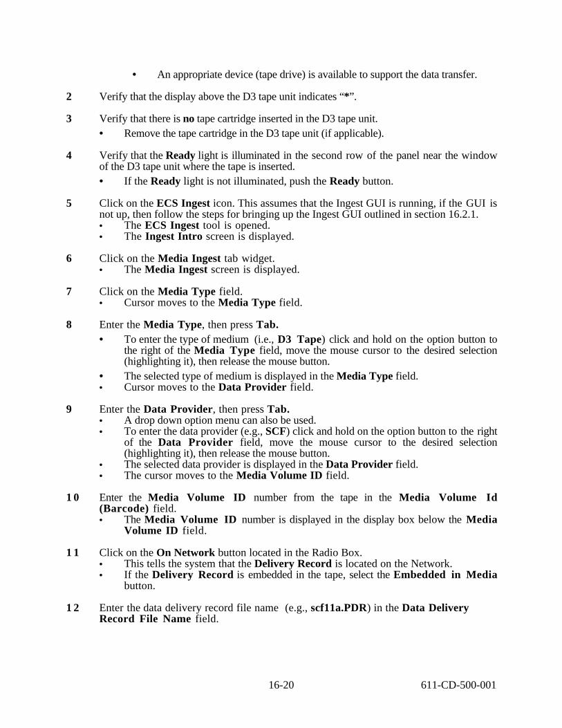
• An appropriate device (tape drive) is available to support the data transfer.
2 Verify that the display above the D3 tape unit indicates “*”.
3 Verify that there is no tape cartridge inserted in the D3 tape unit. • Remove the tape cartridge in the D3 tape unit (if applicable).
4 Verify that the Ready light is illuminated in the second row of the panel near the window of the D3 tape unit where the tape is inserted. • If the Ready light is not illuminated, push the Ready button.
5 Click on the ECS Ingest icon. This assumes that the Ingest GUI is running, if the GUI is not up, then follow the steps for bringing up the Ingest GUI outlined in section 16.2.1. • The ECS Ingest tool is opened. • The Ingest Intro screen is displayed.
6 Click on the Media Ingest tab widget. • The Media Ingest screen is displayed.
7 Click on the Media Type field. • Cursor moves to the Media Type field.
8 Enter the Media Type, then press Tab. • To enter the type of medium (i.e., D3 Tape) click and hold on the option button to
the right of the Media Type field, move the mouse cursor to the desired selection (highlighting it), then release the mouse button.
• The selected type of medium is displayed in the Media Type field. • Cursor moves to the Data Provider field.
9 Enter the Data Provider, then press Tab. • A drop down option menu can also be used. • To enter the data provider (e.g., SCF) click and hold on the option button to the right
of the Data Provider field, move the mouse cursor to the desired selection (highlighting it), then release the mouse button.
• The selected data provider is displayed in the Data Provider field. • The cursor moves to the Media Volume ID field.
1 0 Enter the Media Volume ID number from the tape in the Media Volume Id (Barcode) field. • The Media Volume ID number is displayed in the display box below the Media
Volume ID field.
1 1 Click on the On Network button located in the Radio Box. • This tells the system that the Delivery Record is located on the Network. • If the Delivery Record is embedded in the tape, select the Embedded in Media
button.
1 2 Enter the data delivery record file name (e.g., scf11a.PDR) in the Data Delivery Record File Name field.
16-20 611-CD-500-001

1
2
3
4
5
6
7
8
9
1 0
1 3 Click (once only) on the OK button at the bottom of the GUI. • The GUI OK button is sensitive to being clicked more than once. It is important to
click it dead center once only or D3 ingest is likely to fail.
1 4 Insert the tape cartridge in the D3 tape drive. • The tape cartridge must be inserted within one minute of clicking on the OK button
on the Ingest GUI. • The message "Loading" should be displayed on the D3 tape drive unit panel. • Then the message "Ready" should be displayed on the D3 tape drive unit panel and
the "ready" light should blink on and off for a while. • Avoid clicking the mouse on the Ingest GUI while the D3 tape unit is reading the tape. • Once the extraction command has been executed, the system reads the D3 tape from
the header label, then accesses the data needed for Ingest processing.
1 5 When the data transfer has been completed, wait for the message "Ingest Request Completed.” • The messages "Rewinding" then “Unloading” should be displayed on the D3 tape
drive unit panel as the D3 tape drive unit rewinds and unloads after the data transfer. • Upon completion of the process the D3 tape automatically rewinds and ejects itself
from the tape drive.
1 6 Remove the tape cartridge from the D3 tape drive.
1 7 Select another function by clicking on a widget tab.
1 8 To exit the ECS Ingest tool, select menu path File / Exit.
Table 16.2-15. Performing Media Ingest from D3 Tape -Quick Steps Procedures
S t e p What to Enter or Select Action to Take
ECS Ingest icon Single Click
Media Type Tab widget Press Return
Media Type field Single Click
Enter the Media Type (D3) Press Tab
Enter the Data Provider Press Tab
Enter the Media Volume ID Press Tab
On Network button Single Click
OK push button Single Click
Insert D3 tape cartridge in the D3 Tape Drive Single Click
File / Exit Single Click and drag
16-21 611-CD-500-001

16.3 Interactive Ingest Tool
A data provider can ingest data without direct operator action through the automated network. The interactive ingest is provided by an HTML web server interface that allows authorized science users the capability to ingest data electronically. The Data Provider will access the automated network Ingest HTML home page through Netscape.
The data provider will send a Data Availability Notice (DAN) to the Ingest Subsystem indicating that data is ready for transfer (Section 16.3.1). The DAN identifies parameters such as data source, number of files, and location of data. The Ingest Subsystem generates a Data Availability Acknowledgment (DAA), which is sent to the Data Provider, indicating readiness to ingest the data identified in the DAN. The procedures to start the interactive ingest server and submit and ingest request can be found in (Section 16.3.2). To monitor the status of on-going requests see (Section 16.3.3). To view the ingest Completion status follow the procedures in (Section 16.3.4).
The Activity Checklist table that follows provides an overview of the Interactive Ingest Tool and its process. Column one (Order) shows the order in which tasks should be accomplished. Column two (Role) lists the Role/Manager/Operator responsible for performing the task. Column three (Task) provides a brief explanation of the task. Column four (Section) provides the Procedure (P) section number or Instruction (I) section number where details for performing the task can be found.
Table 16.3-1. Interactive Ingest - Activity Checklist Order Role Task Section
1 Data Provider / DIT
Creating a Data Availability Notice (DAN)
(P) 16.3.1
2 Ingest Subsystem Generate and Send Data Availability Acknowledgement (DAA)
(P) 16.3.1
3 Data Provider Submitting an Ingest Request (P) 16.3.2
4 Data Provider Monitoring On-Going Request Status (P) 16.3.3
5 Data Provider Viewing Ingest Completion Status (P) 16.3.4
16.3.1 Creating a Data Availability Notice (DAN)
Before a Data Provider can ingest data into the ECS system a Data Availability Notice (DAN) must be sent to the Subsystem indicating that data is ready for transfer. The DAN specifies the parameters needed to identify what files are ready for pickup, the location, and how long it will be available in that location. The maximum message length allowed for a DAN is 1 megabyte. More than one DAN may be sent if needed.
Each DAN includes a Message Header, Exchange Data Unit (EDU) Label and Parameter Value Language (PVL) Statements. The Message Header and labels are in a contiguous string, followed by the PVL. The labels and PVL statements are in Standard Formatted Data Unit (SFDU) format.
16-22 611-CD-500-001

More information about SFDU and PVL can be found in the following documents: Consultative Committee for Space Data Systems (CCSDS), Standard Formatted Data Units--Structure and Construction Rules, Consultative Committee for Space Data Systems (CCSDS) and Parameter Value Language Specification (CCSD0006, blue book).
The system will log the receipt of the DAN and assign a request ID number. A summary of the DAN contents is placed in the event log. The Ingest subsystem generates a corresponding ingest request and stores the request on a prioritized list. A Data Availability Acknowledgment (DAA) is sent from Ingest to the Data Provider indicating readiness to ingest the data identified in the DAN.
The procedure that follows explains the information needed to create a DAN. This procedure will assume the Data Provider has already used an xterm or SUN to obtain the DAN template. If you are familiar with the procedure, you may prefer to use the quick-step table at the end of this procedure. If you are new to the system, or have not performed this task recently, you should use the detailed procedure that follows.
1 The DAN Sequence Number is system generated, therefore press Tab. • The cursor moves to the Expiration Time field.
2 Enter the Expiration Time, then press Return. • Time for data deletion from originating system. • The cursor moves to the Originating System field.
3 Enter the Originating System, then press Return. • The originator of the DAN. • The cursor moves to the Aggregate Length field.
4 Enter the Aggregate Length, then press Return. • Total number of bytes to transfer (Sum for all files). • The cursor moves to the Total File Count field.
5 Enter the Total File Count, then press Return. • Total number of files to transfer. • The Cursor moves to the Object field.
6 Enter the Object, then press Return. • The start of file group parameters (repeat for each group of files). • The cursor moves to the Data Type field.
7 Enter the Data Type, then press Return. • ECS Data Type. • Cursor moves to Node Name field.
8 Enter the Node Name, then press Return. • Name of the network node on which the file resides. • The cursor moves to the Descriptor field.
9 Enter the Descriptor, then press Return. • The string.
16-23 611-CD-500-001

1
2
3
4
5
6
7
8
9
1 0
1 1
1 2
1 3
1 4
1 5
• The cursor moves to the Object field.
1 0 Enter the Object, then press Return. • Start of Detached SFDU Header File Object, if appropriate. • The cursor moves to the File ID field.
1 1 Enter the File ID, then press Return. • The File Name. • The cursor moves to the File Type field.
1 2 Enter the File Type, then press Return. • The File Data Type. • The cursor moves to the Directory ID field.
1 3 Enter the Directory ID, then press Return. • The file directory name (i.e., path name). • The cursor moves to the File Size field.
1 4 Enter the File Size, then press Return. • The length of the file in bytes. • The cursor moves to the End Object field.
1 5 Enter the End Object, then press Return. • The End Detached SFDU Header File Object.
Table 16.3-2. Creating Data Availability Notice (DAN) - Quick-Step Procedures
S t e p What to Enter or Select Action to Take
DAN Sequence Number (system generated) press Tab
Enter the Expiration Time press Return
Enter the Originating System press Return
Enter the Aggregate Length press Return
Enter the Total File Count press Return
Enter the Object press Return
Enter the Data Type press Return
Enter the Node Type press Return
Enter the Descriptor press Return
Enter the Object press Return
Enter the File ID press Return
Enter the File Type press Return
Enter the Directory ID press Return
Enter the File Size press Return
Enter the End Object press Return
16-24 611-CD-500-001

16.3.2 Submitting an Ingest Request
The Science Data Provider can access the network ingest subsystem through Netscape. The following procedure describes the automated network ingest of data to ECS from data providers which will be accomplished without direct operator action. This procedure assumes that the DAN has already been created, which describes the location of the available data. The Interactive Ingest Main Form displays three options to the data provider; Create DAN File, Submit Ingest Request, and Monitor On-Going Request Status.
The following procedure will open the Interactive Ingest tool, then submit an ingest request. The Data Provider selects the files to be ingested from a list displayed on the Submit Ingest Request screen. If you are already familiar with the procedures, you may prefer to use the quickstep table at the end of this procedure. If you are new to the system, or have not performed this task recently, you should use the following detailed procedure.
1 Click on the Netscape Navigator icon.
2 Enter the URL of the Ingest Home Page, then press Return. • The Data Provider login page is displayed.
3 Enter the Data Provider name in the ECS Data Provider field, then press Return. • The cursor movers to the Data Provider Password field.
4 Enter the Data Provider Password, in the ECS Data Provider Password field, then press Return.
5 Click on the Submit Ingest Request radio button.
6 Click on the Submit push button. • The Submit Ingest Request screen is displayed. • A list of data files are displayed.
7 Click on the Data File to be ingested. • The data file number appears to the right of Select Requests (s) • More than one file can be selected at one time.
8 Click on the Submit push button. • The Ingest Request has been submitted.
9 Exit the Interactive Ingest system by following menu path File → Quit.
16-25 611-CD-500-001

1
2
3
4
5
6
7
8
9
1
2
3
4
5
6
Table 16.3-3. Submitting an Ingest Request - Quick-Step Procedure S t e p What to Enter or Select Action to Take
Netscape Navigator icon single Click
Enter the URL of the Ingest Home Page press Return
Enter Data Provider press Return
Enter Data Provider Password press Return
Submit Ingest Request radio button single Click
Submit push button single Click
Data File single Click
Submit push button single Click
File → Quit single Click and drag
16.3.3 Monitoring On-Going Request Status
The on-going status of submitted data requests can be viewed by invoking the Interactive Ingest Main Form, then entering the Data Providers name and selecting the Monitor On-Going Request Status radio button. The Ingest Request On-Going Status screen displays all the active requests for the Data Provider. The Ingest Request On-Going Status screen displays each data request, its Request ID number and the acceptance or rejection of the data request. To display more details on a specific data request click on the individual data request, which opens the On-Going Status Monitor screen. From the On-Going Status Monitor screen click on the data request to display the Granule Level status.
The following procedure will open the Interactive Ingest Tool, then view the status of a data request at the granule level. If you are already familiar with the procedure, you may prefer to use the quick-step table at the end of this procedure. If you are new to the system, or have not performed this task recently, you should use the following detailed procedure. If the Interactive Ingest Main Form has already been opened, skip steps 1 through 7, otherwise begin with step 1.
Click on the Netscape Navigator icon.
Enter the URL of the Ingest Home Page, then press Return
Enter the user Password, then press Return.
Enter the Data Provider name, then press Return.
Click on the Monitor On-Going Request Status radio button.
Click on the Submit push button. • The Ingest Request On-Going Status screen is displayed. • The following information is displayed for all active requests;
a Data request file number b Acceptance or rejection of each request. CSystem Request Id number.
16-26 611-CD-500-001

1
2
3
4
5
6
7
8
9
7 Click on a Individual Ingest Request. • The On-Going Status Monitor screen is opened, which displays: • The Request ID. • State of request . • % Complete • Priority • Start Time • End Time
8 Click on the Request ID. • The Granule Level Status Monitor screen for the selected Request ID is opened,
displaying the following information: − The Request ID number. − The Status. − The Percent Complete. − The Data Provider. − The Ingest Type. − The Priority. − The Process Start Time. − The Expiration Time. − The Granule Count. − The Data Volume. − The Data Type. − The Granule Volume. − The Granule State.
9 Exit the Interactive Ingest system by following menu path File → Quit.
Table 16.3-4. Monitoring On-Going Request Status -Quick-Step Procedures
S t e p What to Enter or Select Action to Take
Netscape Navigator icon single Click
Enter the URL of the Ingest Home Page press Return
Enter Password press Return
Enter the Data Provider press Return
Monitor On-Going Request Status radio button single Click
Submit push button single Click
Individual ingest Request single Click
Request ID single Click
File → Quit single Click and drag
16.4 Ingest Polling Process
The ECS Ingest Subsystem supports a transfer mechanism to acquire data from a supplier system (Data Provider). This process is called Polling. There are two Polling processes supported, Polling Ingest with Product Delivery Record (Section 16.4.1), and Polling
16-27 611-CD-500-001

Ingest without Product Delivery Record (Section 16.4.2). Ingest Information Notifications that are received from, and sent to the Data Provider during this process will be addressed in Section 16.4.3. Ingest Archive Verification is discussed in Section 16.4.4.
The Activity Checklist table that follows provides an overview of the Ingest polling Subsystem process. Column one (Order) shows the order in which tasks should be accomplished. Column two (Role) list the Role/Manager/Operator responsible for performing the task. Column three (Task) provides a brief explanation of the task. Column four (Section) provides the Procedure (P) section number or Instruction (I) section number where details for performing the task can be found.
Table 16.4-1. Ingest Polling - Activity Checklist Order Role Task Section
1 DIT Polling Ingest With Product Delivery Record (PDR) (I) 16.4.1
2 DIT Polling Ingest Without (PDR) (I) 16.4.2
3 DIT Ingest Information Notifications (P)16.4.3
4 DIT Ingest Archive Verification (P)16.4.4
5 DIT Deleting Files from the Ingest Polling Directory (P)16.4.5
16.4.1 Polling Ingest With Product Delivery Record
ECS periodically checks on an agreed-upon network location for a Product Delivery Record (PDR) file. The PDR file contains information identical to that in a DAN, see (Section 16.3.1). The Data Provider may have previously transferred the data to a working storage device within ECS, otherwise an ftp “get” will be used to obtain the data from the Data Provider within a specified time window. The Data Provider and the ECS Ingest Subsystem are each equipped with a computer program that invokes an FTP daemon, which automatically polls the server supplying the data.
The periodic polling process detects and then acquires a PDR. The Ingest subsystem then validates the information contained in the PDR. If the system is unable to read the PDR, a Data Availability Acknowledgment (DAA) is sent to the Data Provider indicating an invalid PDR. If the Ingest Subsystem is able to read the PDR, a request ID is assigned and the PDR, and its contents are placed in the Event Log. A DAA is sent to the Data Provider indicating readiness to ingest the data identified in the PDR. Ingest generates a corresponding ingest request and stores the request on a prioritized list. The Ingest function ensures that all required devices are allocated and schedules and performs the data transfer. After the data has been transferred, a Data Delivery Notice is sent to the Data Provider indicating that the archiving of the data identified in the PDR has been completed.
The DIT may monitor the status of any ingest request by using the Monitor/Control screen of the ECS Ingest Tool (Section 16.2.4). The Ingest process is automated, however there are several sequences in which errors can be encountered which will cause the process to stop, requiring Operator intervention (see Section 16.4.4). The Event log will be updated during each
16-28 611-CD-500-001

phase of the Ingest process, therefore the DIT can easily access the status of any request. If intervention is required, the Computer Operator and/or DIT can Suspend, Cancel or Resume the Ingest process by using the Operator Tools of the ECS Ingest subsystem (Section 16.2.5).
16.4.2 Polling Ingest Without Product Delivery Record
This mechanism is planned to be used for the transfer of certain ancillary products required for data processing. The ingest subsystem periodically polls an agreed-upon network location for the presence of data. All data at the specified location are assumed to make up a collection of ingest data with one file per data granule. The ingest function automatically performs an ftp get from the Data Provider within a system tunable time window. The data goes through the usual ingest verification process of format conversion and metadata extraction and validation, with status messages going to the event log. When the ingest process has been completed, a message is sent to the History Log (Section 16.2.3), the polling interval is reset, and the system enters a wait state.
16.4.3 Ingest Information Notifications
During the Ingest process several Information Notices are sent to the Data Provider, the Ingest subsystem, and the event log. The first notice is from the Data Provider, informing the ingest subsystem that data is ready for transfer. This notice is called a Data Availability Notice (DAN) or Product Delivery Record (PDR). Both notices contain the same information, such as data source, number of files, and location of data. When the subsystem receives the DAN or PDR it sends a message back to the Data Provider to acknowledge the receipt of the DAN or PDR. The return message is called a Data Availability Acknowledgment (DAA). The Ingest system automatically logs all of the messages into the event log, therefore the DIT can obtain the current status of an ingest request at any time. If an error occurs during the ingest process another DAA is sent to the Data Provider and to the event log explaining the problem. When the ingest process has been completed, the system generates a DATA Delivery Notice (DDN), which is sent to the Data Provider. The Data Provider then returns a Data Delivery Acknowledgment (DDA) in response to the DDN and terminates the session. Ingest provides a status message to the Ingest History Log when the transaction is complete.
The following section describes the steps needed to view the information contained in the notices for a specific Data Provider. The DIT can view the contents of any notice through the ECS Ingest tool. If you are familiar with the procedure, you may prefer to use the quick-step table at the end of this procedure. If you are new to the system, or have not performed this task recently, you should use the detailed procedure that follows.
1 Click on the ECS Ingest icon. This assumes that the Ingest GUI is running, if the GUI is not up, then follow the steps for bringing up the Ingest GUI outlined in section 16.2.1. • The ECS Ingest tool is now open. • The Ingest Introduction screen is displayed.
2 Click on the Monitor/Control tab widget. • The Monitor/Control screen is displayed.
16-29 611-CD-500-001

1
2
3
4
5
6
7
8
3 Click on the Data Provider button, in the radio box. • The cursor moves to the periodic box to the right of the Data Provider.
4 Enter the Data Provider, then press Return.
5 Click on the Text view button.
6 Click on the OK push button. • All ongoing ingest requests for the Data Provider are displayed, including the
Informational Notices.
7 Highlight an individual request, then double Click. • Text is displayed at a granule level.
8 Exit the ECS Ingest tool by following menu path File → Exit.
Table 16.4-2. Ingest Information Notification - Quick-Step Procedures S t e p What to Enter or Select Action to Take
ECS Ingest icon single Click
Monitor/Control tab widget single Click
Data Provider radio button single Click
Enter the Data Provider press Return
Text view button single Click
OK push button single Click
Highlight individual request double Click
Follow menu path File → Exit
16.4.4 Ingest Archive Verification
In an effort to verify that the data ingested has been archived successfully, the following steps are used to verify whether data is present on the archive. This procedures makes it unnecessary to get into any archive software. This procedure is pretty straight forward and safe so don’t worry about doing anything strange and wonderful to the system. Good luck. The aster, ceres, data, l7, and modis directories correspond directly to tape volumes in the system. The data is listed in the Amass data base and is actually on tape.
1 Log on to any workstation.
2 Type in your login and password.
3 Enter telnet <hostname>. Example telnet g0drg01.
4 Set your terminal display environment using the command: setenv DISPLAY <hostname:0.0>
5 Type in your login and password.
16-30 611-CD-500-001

1
2
3
4
5
6
7
8
6 Change directory to the directory containing the location of the archive data: cd /dss_stk1
7 Enter ls to list the contents of the directory. • Should see OPS, TS1, TS2, and test mode directories
8 Change directory to the directory containing the mode used: cd [ OPS, TS1, TS2, test]
9 Enter ls to list the contents of the directory. • Should see aster, ceres, data, 17, and modis directories
1 0 Change directory to the directory containing the location of the type of data ingested: cd [ aster, ceres, data, 17, and modis]
1 1 Enter ls to list the contents of the directory. • Should see data listed on tape in the archive.
Table 16.4-3. Ingest Archive Verification - Quick-Step Procedures S t e p What to Enter or Select Action to Take
Telnet <hostname> press Return
UserId press Return
Password press Return
setenv DISPLAY <hostname:0.0> press Return
cd /dss_stk1 press Return
cd press Return
cd press Return
ls press Return
[ OPS, TS1, TS2, test]
[ aster, ceres, data, 17, and modis]
16.4.5 Deleting Files from the Ingest Polling Directory
The Ingest Polling Directory does not get cleaned up automatically after a successful archive. At the present time this process is being done manually. The EcInPollClean script was delivered in Drop4PX to manually clean the EDOS polling directory, which is where the problem was first identified. The EcInPollClean script will clean all files in the specified directory (to include all files in subdirectories, if any) that are older than the specified time. The script requires two inputs, the name of the path containing the files to be deleted, and the number of days. If you are already familiar with the procedure, you may prefer to use the quick-step table at the end of the procedure. If you are new to the system, you should use the following detailed procedures:
1 Log in to any workstation using your user identifier and password by typing YourUserID, and then press Return. • A password prompt is displayed.
2 Enter YourPassword, then press Return.
16-31 611-CD-500-001

1
2
3
4
5
6
7
8
9
• You are authenticated as yourself.
3 Enter telnet <hostname>. Example telnet g0drg01.
4 Enter YourUserID, and then press Return. • A password prompt is displayed.
5 Enter YourPassword, then press Return. • You are authenticated as yourself.
6 Set your terminal display environment using the following command: setenv DISPLAY <hostname:0.0>
7 Change directory to the directory containing the Ingest EcInPollClean script file: cd /usr/ecs/<mode>/CUSTOM/utilities
8 Enter ls to list the contents of the directory:
9 Execute the EcInPollClean script using the following command: EcInPollClean <path name> <number of day>
Table 16.4-4. Deleting Files From the Ingest Polling Directory -Quick-Steps
S t e p What to Enter or Select Action to Take
YourUserID press Return
YourPassword press Return
telnet <hostname> press Return
YourUserID press Return
YourPassword press Return
setenv DISPLAY <hostname:0.0> press Return
cd /usr/ecs/<mode>/CUSTOM/utilities press Return
Ls press Return
EcInPollClean <path name> <number of day> press Return
16.5 Recovery from a Data Ingest Failure
When an ingest fault (error) occurs, there may be a requirement for action to recover from the error. Recovery actions may be made necessary by invalid DAN contents or other errors that result in data ingest failure. When a fault (error) occurs, the following actions occur:
• The processing of the ingest request stops. • A message is sent to the Ingest/Distribution Technician and the data provider with a
brief description of the problem.
16-32 611-CD-500-001

The Ingest/Distribution Technician may use the Ingest GUI Monitor/Control screen, the Ingest History Log (refer to the section on Ingest Status Monitoring) and/or the following log files (in the /usr/ecs/mode/CUSTOM/logs directory on the ingest host machine) to review the failure event:
• EcInReqMgr.ALOG (ingest request manager log). • EcInAuto.ALOG (automated ingest log). • EcInPolling.ALOG (polling ingest log). • EcInGran.ALOG (granule server log). • EcInGUI.ALOG (Ingest GUI log).
In addition, it is possible to check the ECS Event Log (for events related to ingest failure) using the ECS Event Log Browser tab on the Management Data Access (MDA) GUI.
This section contains some examples of faults that are likely to occur, describes the notifications provided, and proposes operator actions in response to each fault situation. The specific recovery actions may vary due to operator preference or local DAAC policy.
The Activity Checklist table that follows provides an overview of the Recovery from a Data Ingest failure process. Column one (Order) shows the order in which tasks should be accomplished. Column two (Role) list the Role/Manager/Operator responsible for performing the task. Column three (Task) provides a brief explanation of the task. Column four (Section) provides the Procedure (P) section number or Instruction (I) section number where details for performing the task can be found.
Table 16.5-1. Recovery from a Data Ingest Failure - Activity Checklist Order Role Task Section
1 DIT Troubleshooting a Data Ingest Failure (P)16.5.1
2 DIT Recovering from a Faulty DAN (P)16.5.2
3 DIT Recovering from Exceeding the Volume Threshold (P)16.5.3
4 DIT Recovering from Exceeding the Maximum Number of Concurrent Requests
(P)16.5.4
5 DIT Recovering from Insufficient Disk Space (I) 16.5.5
6 DIT Recovering from Exceeding the Expiration Date/Time Period
(P)16.5.6
7 DIT Recovering from File Transfer (ftp) Error (P)16.5.7
8 DIT Recovering from Processing Errors (P)16.5.8
16.5.1 Troubleshooting a Data Ingest Failure
When troubleshooting a data ingest failure, use the procedure that follows. The procedure starts with the assumption that all applicable servers and the Ingest GUI are currently running and the Monitor/Control (All Requests) screen is being displayed. Upon receipt of the operator alert, use the Monitor/Control screen scroll bars as necessary to
identify the faulty ingest request. • When there is a data ingest failure, the system provides the following three responses:
− Logs the error. − Alerts the Ingest/Distribution Technician.
16-33 611-CD-500-001

− Returns a DDN to the data provider indicating the nature of the failure. Review the information concerning the faulty ingest request. If additional information is needed, open and read the appropriate log file in the
/usr/ecs/mode/CUSTOM/logs directory on the ingest host machine. • EcInReqMgr.ALOG (ingest request manager log). • EcInAuto.ALOG (automated ingest log). • EcInPolling.ALOG (polling ingest log). • EcInGran.ALOG (granule server log). • EcInGUI.ALOG (Ingest GUI log).
Perform the appropriate recovery procedure depending on the nature of the problem: • Recovering from a Faulty DAN. • Recovering from Exceeding the Volume Threshold. • Recovering from Exceeding the Maximum Number of Concurrent
Requests. • Recovering from Insufficient Disk Space. • Recovering from Exceeding the Expiration Date/Time Period. • Recovering from File Transfer (ftp) Error. • Recovering from Processing Errors.
16.5.2 Recovering from a Faulty DAN
If the DAN/PDR is invalid, the data provider must submit a new DAN. The DIT should respond to the error by contacting the data provider to give an alert that the ingest failure has occurred, provide as much information as possible about why the failure occurred, and determine whether the data ingest request will be re-initiated. When working to recover from an invalid DAN/PDR, use the procedure that follows. The procedure starts with the following assumption that the Ingest GUI Monitor/Control (All Requests) screen is being displayed. 1 Upon receipt of the operator alert, use the Monitor/Control screen scroll bars as
necessary to identify the faulty ingest request. 2 Review the information concerning the faulty ingest request. 3 If additional information is needed, open and read the appropriate log file in the
/usr/ecs/mode/CUSTOM/logs directory on the ingest host machine. 4 Contact (by telephone or e-mail) the data provider to discuss the following issues:
• Report the ingest failure. • Discuss what has been discovered from reviewing the failure event data. • Determine whether the data provider will re-initiate the data ingest request with a new
DAN. 5 If the data ingest request is to be re-initiated, monitor the subsequent ingest as described in
the procedure for Monitoring Ingest Requests.
16.5.3 Recovering from Exceeding the Volume Threshold
Data Ingest may fail for reasons other than invalid DAN/PDR contents. For example, if the specified system volume threshold has been exceeded, the system sends a DDN to the Data Provider indicating that the system is full and an attempt should be retried again later. If a data provider’s volume threshold has been exceeded, use the procedure that follows. The procedure starts with the following assumption that the Ingest GUI Monitor/Control (All Requests) screen is being displayed.
16-34 611-CD-500-001

1 Upon receipt of the operator alert, use the Monitor/Control screen scroll bars as necessary to identify the faulty ingest request.
2 Review the information concerning the faulty ingest request. 3 If additional information is needed, open and read the appropriate log file in the
/usr/ecs/mode/CUSTOM/logs directory on the ingest host machine. 4 If it is decided to increase the system volume threshold, first click on the Operator Tools
tab. • The Operator Tools screen is displayed.
5 Click on the Modify System Parameters tab. • The Modify System Parameters screen is displayed.
6 Click in the New: field corresponding to Volume Threshold, then type the numerical value for the new volume threshold. • The current value of the volume threshold is printed on the corresponding line for
reference purposes. 7 Click on the OK button at the bottom of the Operator Tools: Modify System
Parameters tab to save the changes to system parameters. • The changes are invoked.
8 Click on the Monitor/Control tab. • The Monitor/Control screen is displayed.
9 Click on the All Requests button. • Alternatively, either a particular Data Provider or Request ID may be specified as
described in the procedure for Monitoring Ingest Requests. 1 0 Click on the Text View button. 11 If the data ingest request is to be re-initiated, monitor the subsequent ingest as described in
the procedure for Monitoring Ingest Requests.
16.5.4 Recovering from Exceeding the Maximum Number of Concurrent Requests
If the specified system request threshold has been exceeded, the system sends a DDN to the Data Provider indicating that the system is full and an attempt should be retried again later. If a data provider’s request threshold has been exceeded, use the procedure that follows to increase the system request threshold. The procedure starts with the following assumptions that the Ingest GUI Monitor/Control (All Requests) screen is being displayed. 1 Upon receipt of the operator alert, use the Monitor/Control screen scroll bars as
necessary to identify the faulty ingest request. 2 Review the information concerning the faulty ingest request. 3 If additional information is needed, open and read the appropriate log file in the
/usr/ecs/mode/CUSTOM/logs directory on the ingest host machine. 4 If it is decided to increase the system request threshold, first click on the Operator Tools
tab. • The Operator Tools screen is displayed.
5 Click on the Modify System Parameters tab. • The Modify System Parameters screen is displayed.
6 Click in the New: field corresponding to Request Threshold, then type the numerical value for the new volume threshold. • The current value of the request threshold is printed on the corresponding line for
reference purposes. 7 Click on the OK button at the bottom of the Operator Tools: Modify System
Parameters tab to save the changes to system parameters. • The changes are invoked.
16-35 611-CD-500-001

8 Click on the Monitor/Control tab. • The Monitor/Control screen is displayed.
9 Click on the All Requests button. • Alternatively, either a particular Data Provider or Request ID may be specified as
described in the procedure for Monitoring Ingest Requests. 1 0 Click on the Text View button. 11 If the data ingest request is to be re-initiated, monitor the subsequent ingest as described in
the procedure for Monitoring Ingest Requests.
16.5.5 Recovering from Insufficient Disk Space
After the receipt of the DAN, a disk space allocation is requested from the Data Server, and a timeout timer for the disk allocation is set. In the event that the Data Server has insufficient disk space, the time-out timer will expire. The Ingest Subsystem notifies the operator that the ingest request is waiting for Data Server disk allocation. At present the Ingest/Distribution Technician has no real option for responding to the problem except perhaps to discuss the situation with the system administrator.
16.5.6 Recovering from Exceeding the Expiration Date/Time Period
If data are unavailable but the time period during which that data were to have been made available has expired, the error is logged in the event log, and a DDN is sent to the Data Provider indicating expiration date/time exceeded. The Ingest/Distribution Technician receives an alert on his/her screen, then contacts the data provider to resolve the problem. If a data provider’s expiration date/time period has been exceeded, use the procedure that follows. The procedure starts with the assumption that the Ingest GUI Monitor/Control (All Requests) screen is being displayed. 1 Upon receipt of the operator alert, use the Monitor/Control screen scroll bars as
necessary to identify the faulty ingest request. 2 Review the information concerning the faulty ingest request. 3 If additional information is needed, open and read the appropriate log file in the
/usr/ecs/mode/CUSTOM/logs directory on the ingest host machine. 4 Contact (by telephone or e-mail) the data provider to discuss the following issues:
• Report the ingest failure. • Discuss what has been discovered from reviewing the failure event data. • Determine whether the data provider will re-initiate the data ingest request.
If the data ingest request is to be re-initiated, monitor the subsequent ingest as described in the procedure for Monitoring Ingest Requests.
16.5.7 Recovering from File Transfer (ftp) Error
After numerous unsuccessful data transfer retries, an error is logged into the event log, the Ingest/Distribution Technician is notified and a DDN is sent to the Data Provider indicating ftp failure. The Ingest/Distribution Technician reviews all current ingest requests using the Operator Tool of the ECS Ingest GUI to determine whether other communication-related failures have occurred and may consult with the data provider(s) to resolve the problem. If it is necessary to recover from a file transfer error, use the procedure that follows. The procedure starts with the assumption that the Ingest GUI Monitor/Control (All Requests) screen is being displayed. 1 Upon receipt of the operator alert, use the Monitor/Control screen scroll bars as
necessary to identify the faulty ingest request.
16-36 611-CD-500-001

2 Review the information concerning the faulty ingest request. 3 If additional information is needed, open and read the appropriate log file in the
/usr/ecs/mode/CUSTOM/logs directory on the ingest host machine. 4 Click on the Ingest GUI Operator Tools tab.
• The Operator Tools screen is displayed. 5 Click on the Modify System Parameters tab.
• The Modify System Parameters screen is displayed. 6 Review the current value for Communication Retry Count. 7 If it is decided to increase the communication retry count, follow the procedure for
Modifying System Parameters. 8 If the data ingest request is to be re-initiated, monitor the subsequent ingest as described in
the procedure for Monitoring Ingest Requests.
16.5.8 Recovering from Processing Errors
Ingest processing errors may require Ingest/Distribution Technician intervention. The following problems are examples of processing errors.
• Missing Required Metadata. • Unknown Data Type. • Template Out of Synchronization (Sync). • Unavailable File Type. • Metadata Validation Error. • Missing Optional Data Files.
If it is necessary to recover from a processing error, use the procedure that follows. The procedure starts with the assumption that the Ingest GUI Monitor/Control (All Requests) screen is being displayed. 1 Upon receipt of the operator alert, use the Monitor/Control screen scroll bars as
necessary to identify the faulty ingest request. 2 Review the information concerning the faulty ingest request. 3 If additional information is needed, open and read the appropriate log file in the
/usr/ecs/mode/CUSTOM/logs directory on the ingest host machine. 4 If the processing error involves missing required metadata or an unknown data type,
contact (by telephone or e-mail) the data provider to request the data provider to make the necessary corrections and re-initiate ingest.
5 If the processing error involves an out-of-sync template or an unavailable file type, submit a trouble ticket in accordance with the trouble ticketing procedures.
6 If the processing error involves a metadata validation error or missing optional data files and if the processing template instructions indicate to continue inserting the data, contact (by telephone or e-mail) the data provider to provide notification that the data have been flagged as bad. • If the processing template instructions indicate to continue inserting the data, the
following events occur: − The error is logged in the event log, − The data are flagged as bad. − A preprocessing failure alert for each data granule appears on the
Ingest/Distribution Technician’s screen. − A Metadata Problem Report is generated.
7 If the processing error involves a metadata validation error or missing optional data files and if the processing template instructions require the rejection of the data, contact (by
16-37 611-CD-500-001
telephone or e-mail) the data provider to request the data provider to make the necessary corrections and re-initiate ingest. • If the template instructions require the rejection of the data, the normal notices and alerts
are sent, including a DDN to the external data provider indicating the preprocessing failure.
8 If the data ingest request is to be re-initiated, monitor the subsequent ingest as described in the procedure for Monitoring Ingest Requests.
16.6 Document Ingest
The Ingest subsystem will not include any capabilities for document ingest in B.0. All ingest will be done manually by operators via ftp pull. Operators are notified of the need to pull a document by phone or e-mail.
The ingest format will remain as originally planned, i.e., it will follow the established document ingest formats. That is, the document submitter must prepare a set of document files in one of the approved ECS formats, an accompanying valid metadata file, and a valid DAN.
The document data server (DDSRV) host will include a directory to keep B.0 ingest requests. The directory name is TBS. By operational procedures, operators are expected to create a subdirectory in that directory for each ingest and deposit the files as ingested into that subdirectory. The purpose of the subdirectory is to retain ingested material for subsequent "real" ingest into ECS once the DDSRV and the document ingest functions are implemented. The naming conventions for these subdirectories are TBS.
The documents will be placed by operational procedure into directories on the DDSRV Netscape Server host. The directory names must be in compliance with B.0 directory naming conventions, but are otherwise at the discretion of DAAC Ops. DAAC Ops will be responsible for creating web pages on the DDSRV Netscape host which point to these documents, and provide links to these web pages from relevant other ECS web pages.
16.6.1 Document Inserts From Within ECS
Documents generated automatically within ECS will be associated with fixed pathnames on the DDSRV host (if the DDSRV will store always only one occurrence of the document), or fixed directories on the DDSRV host (if there will be multiple instances of the document kept on the DDSRV).
Documents which are planned for insertion into the DDSRV from within ECS (e.g., algorithm documentation) by manual procedure, will have their procedure changed to provide ingest documentation, generate a DAN, have the document placed into an "archive" directory, and then have the document placed into a DDSRV directory.
The providers of documents generated automatically by ECS or inserted manually, are responsible for having web pages produced and stored on the DDSRV Netscape server host pointing to the documents. The web pages must be compliant with the ECS HTML guidelines. DAAC operations are free to add links to them in other ECS web pages.
16-38 611-CD-500-001

DAAC Ops will maintain and update any web pages needed to support access to the documents on the B.0 DDSRV web server. The web pages are placed into directories named in accordance with the Release B.0 directory naming conventions, but the names are otherwise at the discretion of DAAC Ops
There is no guarantee that the B.0 URLs for DDSRV documents will be valid for these documents in B.1.
If documents are updated, the updated versions need to go through the manual ingest procedure to ensure that they can be ingested into B.1.
DDSRV is responsible for any configuration tailoring of the DDSRV Netscape Server.
SSI&T will need to produce and save a DAN for the documents which are part of a DAP/SSAP.
16.6.2 Scanning Documents
This procedure will take you step by step in operating the HP Jetscan Scanner to create a temporary file for data to be downloaded to the system for archiving documents. If you are new to the system, or have not performed this task recently, you should use the following detailed procedure;
1 Click on the Start button.
2 Select Programs.
3 Select TexBridge Pro 96 to access the TexBridge software for scanning documents consisting of both text and tables. • Select TexBridge Pro 96 once again within the second column. • When the TexBridge Pro 96 screen appears insure that the following 5 options are listed as follows.
Page Quality / Page Orientation / Original Document Layout / Document Recomposition / Brightness
Auto Auto Auto Rec o mpose Al l Auto
4 Select Save Image Defer OCR this is the 8th icon to far right of the screen.
5 Load documents into HP ScanJet feeder.
6 Click Go this will start the scanning process.
7 When the document has been scanned, save the document with a valid file name.
This process will require a filename to be created “when saving” the data before the datainformation can be accessed in the system for verification.
16-39 611-CD-500-001

1
2
3
4
5
6
7
1
2
3
4
5
6
7
Table 16.6-1. Scanning Documents - Quick-Step Procedures S t e p What to Enter or Select Action to Take
1 Select Start from the Windows 95 menu bar single Click
2 Select Programs single Click
3 Select TexBridge Pro 96 single Click
4 If scanning both text and table select Save Image Defer OCR
single Click
5 Load documents into HP ScanJet feeder
6 Click Go single Click
16.6.3 Accessing Scanned Documents
After a document has been scanned, it should be checked to ensure that it has been properly scanned and saved. The procedure for accessing scanned documents starts with the assumption that the Ingest/Distribution Technician has logged in to Windows 95 on the applicable personal computer (PC). Upon completion of the above procedure follow the step to access the scanned files you’ve just created.
Select Start from the Windows 95 menu bar.
Select Programs
Select Windows Explorer from the file menu.
Click Program files under this option
Select TexBridge Pro 96
Click folder called Tiffs
Select the filename/s you created from the documents you’ve just scanned.
Table 16.6-2. Opening Tiffs File - Quick-Step Procedures S t e p What to Enter or Select Action to Take
Select Start from the Windows 95 menu bar single Click
Select Programs single Click
Select Windows Explorer single Click
Select Program Files single Click
Select TexBridge Pro 96 single Click
Click Tiffs file single Click
Select the file you created single Click
16-40 611-CD-500-001

1
2
3
4
5
6
16.7 ECS Science Data Server Operator Tool
The ECS Science Data Server Operator tool has two tab widgets; Data Types, and System Requests. The Data Types (Section 16.6.1) screen provides the DIT the capability to view and add data types in the system. The System Requests (Section 16.6.2) screen provides the capability to monitor the processing of system requests.
The Activity Checklist table that follows provides an overview of the Science Data Server Operator tool and its functions. Column one (Order) shows the order in which tasks should be accomplished. Column two (Role) lists the Role/Manager/Operator responsible for performing the task. Column three (Task) provides a brief explanation of the task. Column four (Section) provides the Procedure (P) section number or Instruction (I) section number where details for performing the task can be found.
Table 16.7-1. ECS Science Data Server Operator Tool -Activity Checklist
Order Role Task Section
DIT Starting the Science Data Server Operator GUI (P)16.7.1
DIT View Science Data Server Data Type Information (P)16.7.2
DIT Add Science Data Server Data Types (P)16.7.3
DIT View Science Data Server Descriptor Information (P)16.7.4
DIT Monitor Science Data Server Request Processing (P)16.7.5
DIT Change Science Data Server Polling Rate (P)16.7.6
16.7.1 Starting the Science Data Server Operator GUI
Starting the Science Data Server Operator GUI in normal operations will be just a matter of clicking an icon that appears on your desktop. Because the desktop configurations have not been installed to date it will be necessary to follow the interim procedure described below. Starting the Science Data Server Operator GUI assumes that the applicable servers are running and the DIT has logged in. If you are already familiar with the procedure, you may prefer to use the quick-step table at the end of the procedure. If you are new to the system, you should use the following detailed procedures:
1 Type xhost + at the command shell prompt and then press Return.
2 Bring up the Science Data Server Operator GUI server, if it has not already been brought up. From a SUN workstation or NCD X-Term terminal telnet into the Science Data Server Operator GUI Server. Enter telnet <hostname>. Example telnet g0acs03.
3 Log into the Science Data Server Operator workstation using your user identifier and password by typing YourUserID, and then press Return. • A password prompt is displayed.
4 Enter YourPassword, then press Return.
16-41 611-CD-500-001

1
2
3
4
5
6
7
8
9
• You are authenticated as yourself.
5 Set your terminal display environment using the following command: setenv DISPLAY <hostname:0.0>
6 Select the mode you are working in using the following command: <mode>ts1, ts2, or ops
7 Change directory to the directory containing the Science Data Server Operator GUI command file: cd/usr/ecs/<mode>/CUSTOM/utilities
8 List the contents of the directory to locate the Science Data Server Operator GUI start script using the following command: ll or ls
9 Start the Science Data Server Operator GUI using the following command: EcDsSdSrvGuiStart <mode>
• The ECS Science Data Server Operator tool is opened. • The Science Data Server – Data Types screen is displayed.
Table 16.7-2. Starting Science Data Server Operator GUI - Quick-Steps S t e p What to Enter or Select Action to Take
xhost + press Return
telnet <hostname> press Return
YourUserID press Return
YourPassword press Return
setenv DISPLAY <hostname:0.0> press Return
<mode> press Return
cd /usr/ecs/<mode>/CUSTOM/utilities press Return
ll or ls press Return
EcDsSdSrvGuiStart <mode> press Return
16.7.2 View the Science Data Server Data Type Information
The DIT can view Science Data Server data type information by viewing the entries on the Science Data Server – Data Types screen. Entries are listed by Archive ID, Earth Science Data Type name, version number, and a brief description. The listing includes all of the entries in the Science Data Server database.
The following procedure explains how to view Science Data Server data type information. If you are already familiar with the procedure, you may prefer to use the quick-step table at the end of the procedure. If you are new to the system, you should use the following detailed procedures:
16-42 611-CD-500-001
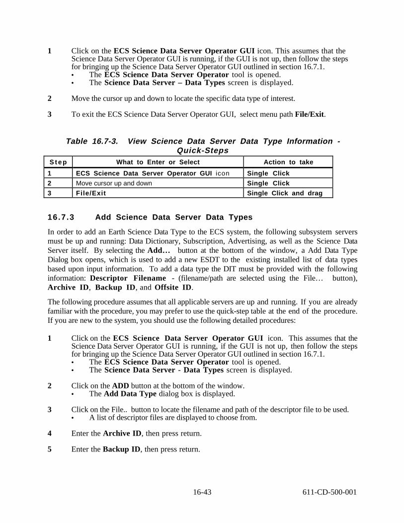
1 Click on the ECS Science Data Server Operator GUI icon. This assumes that the Science Data Server Operator GUI is running, if the GUI is not up, then follow the steps for bringing up the Science Data Server Operator GUI outlined in section 16.7.1. • The ECS Science Data Server Operator tool is opened. • The Science Data Server – Data Types screen is displayed.
2 Move the cursor up and down to locate the specific data type of interest.
3 To exit the ECS Science Data Server Operator GUI, select menu path File/Exit.
Table 16.7-3. View Science Data Server Data Type Information -Quick-Steps
S t e p What to Enter or Select Action to take
1 ECS Science Data Server Operator GUI icon Single Click
2 Move cursor up and down Single Click
3 File/Exit Single Click and drag
16.7.3 Add Science Data Server Data Types
In order to add an Earth Science Data Type to the ECS system, the following subsystem servers must be up and running: Data Dictionary, Subscription, Advertising, as well as the Science Data Server itself. By selecting the Add… button at the bottom of the window, a Add Data Type Dialog box opens, which is used to add a new ESDT to the existing installed list of data types based upon input information. To add a data type the DIT must be provided with the following information: Descriptor Filename - (filename/path are selected using the File… button), Archive ID, Backup ID, and Offsite ID.
The following procedure assumes that all applicable servers are up and running. If you are already familiar with the procedure, you may prefer to use the quick-step table at the end of the procedure. If you are new to the system, you should use the following detailed procedures:
1 Click on the ECS Science Data Server Operator GUI icon. This assumes that the Science Data Server Operator GUI is running, if the GUI is not up, then follow the steps for bringing up the Science Data Server Operator GUI outlined in section 16.7.1. • The ECS Science Data Server Operator tool is opened. • The Science Data Server - Data Types screen is displayed.
2 Click on the ADD button at the bottom of the window. • The Add Data Type dialog box is displayed.
3 Click on the File.. button to locate the filename and path of the descriptor file to be used. • A list of descriptor files are displayed to choose from.
4 Enter the Archive ID, then press return.
5 Enter the Backup ID, then press return.
16-43 611-CD-500-001

6 Enter the Offsite ID, then press return.
7 Click on the OK button. • The display box and criteria fields are cleared.
8 Click on the Data Types tab to verify that the data type was added. • The Science Data Server - Data Types screen is displayed. • The Data Types screen displays the following information; ESDT ShortName,
Version ID, Descriptor filenames/path, DDL filename/path, and the desired Archive ID.
• Several things should happen in succession for an ESDT to be successfully added. First the data dictionary is accessed, an event is generated on the subscription server, the advertising server is accessed, and finally a message will appear on the GUI stating Data type added successfully.
9 To verify the data type was successfully added, you will have to access the Inventory database that the requested data type can be found in the data base. You must first exit the ECS Science Data Server Operator tool by selecting the menu path File / Exit.
1 0 Change directory by typing the following command: cd /usr/ecs/{MODE}/CUSTOM/utilities
1 1 Setup the environment using the following command: setenv MODE {MODE}
1 2 Type: source EcCoEnvCs
13 Enter the Inventory database by typing: isql -Sg0acg01_sqs222_srvr -UEcDsScienceDataServer -PnklQWabc
1. select * 2. from DsMdCollections 3. where ShortName=”M0D00” “AST_08” for example. 4. g o
1. select ShortName, lastUpdate 2. from DsMdGranules 3. g o
1. sp_help DsMdGranule
1 4 The configuration file EcDsScienceDataServer.CFG has variable DSSDESCDIR, DSSDLLDIR, and DSSEVTDIR indicating the appropriate directories. For other verification you may view the Debug and A.LOGs for DDICT (collection level information), IOS (Advertisements), SbEventSERVER (Event information was added). To view the configuration file you must first change directory by using the following command: cd cfg /usr/ecs/{MODE}/CUSTOM/cfg
1 5 List directory contents by using the following command:
16-44 611-CD-500-001

1
2
3
4
5
6
7
8
9
1 0
1 1
1 2
1 3
ll (or) ls
16 To view the configuration file type: cat (Configuration File Name). Example cat EcDsScienceDataServer.CFG • The configuration file contains the following information:
Groups (Keywords that define an ESDT’s metadata, advertised services, subscribable events, data dictionary information, validation criteria and science parameters) Objects (ShortName) Data Location = “MFC”
Table 16.7-4. Add Science Data Server Data Types - Quick-Steps S t e p What to Enter or Select Action to Take
ECS Science Data Server Operator icon Single Click
ADD Single Click
File .. Single Click
Archive ID Press Return
Backup ID Press Return
Offsite ID Press Return
OK button Single Click
Data Type tab Single Click
File/Exit Single Click and drag
cd /usr/ecs/{MODE}/CUSTOM/utilities press Return
setenv MODE {MODE} press Return
source EcCoEnvCsh press Return
Isql - Sg0acg01_sqs222_srvr –UecDsScienceDataServer -PnklQWabc
press Return
1. select * press Return
2. from DsMdCollection press Return
3. where ShortName=”M0D00” (example only) press Return
4. go press Return
1. select ShortName, lastUpdate press Return
2. from DsMdGranule press Return
3. go press Return
1. sp_help DsMdGranule press Return
1 4 cd cfg press Return
1 5 ll press Return
1 6 cat (Configuration File Name) press Return
16-45 611-CD-500-001

16.7.4 View Science Data Server Descriptor Information
The DIT can view the Science Data Server descriptor file information. The following procedure will display descriptor information for a specific data type. If you are already familiar with the procedures, you may prefer to use the quick-step tables at the end of this procedure. If you are new to the system, or have not performed this task recently, you should use the detailed procedures that follow.
1 Click on the ECS Science Data Server Operator GUI icon. This assumes that the Science Data Server Operator GUI is running, if the GUI is not up, then follow the steps for bringing up the Science Data Server Operator GUI outlined in Section 16.7.1. • The ECS Science Data Server Operator tool is opened. • The Science Data Server – Data Types screen is displayed.
2 Click on the View button. • The Descriptor Information screen is displayed. • View descriptor information, which consists of groups, objects, and keywords that
define an ESDT.
3 Click on the Close button to return to the Data Type screen. • The Science Data Server – Data Types screen is displayed.
4 To exit the ECS Science Data Server Operator GUI, select menu path File/Exit.
Table 16.7-5. View Science Data Server Descriptor Information -Quick-Steps
S t e p What to Enter or Select Action to take
1 ECS Science Data Server Operator GUI icon Single Click
2 View Single Click
3 Close Single Click
4 File/Exit Single Click and drag
16.7.5 Monitor Science Data Server Request Processing
The Science Data Server Operator GUI System Management Requests screen provides the DIT with the capability to monitor and change priority on a request that is being processed by the Science Data Server subsystem.
If you are already familiar with the procedure, you may prefer to use the quick-step table at the end of the procedure. If you are new to the system, you should use the following detailed procedures:
1 Click on the ECS Science Data Server Operator GUI icon. This assumes that the Science Data Server Operator GUI is running, if the GUI is not up, then follow the steps for bringing up the Science Data Server Operator GUI outlined in Section 16.7.1. • The ECS Science Data Server Operator tool is opened.
16-46 611-CD-500-001

• The Science Data Server – Data Types screen is displayed.
2 Click on the System Requests tab. • The System Management Request screen is displayed. • The Request ID, Requestor, Component, Service Request, Status, and Priority are
displayed.
3 To change the priority of a specific request, select the desired request from the request list displayed in the System Management Requests window whose priority must be changed. • The request is highlighted.
4 Press the Apply Priority push button. • The action is successful if no error dialog appears. • The desired request’s priority changes to “High.” • A check mark will appear in the left hand column to show which request item was
changed.
5 Press the Refresh push button. • The system management request list is updated with the most recent request list.
6 Verify that the desired request’s priority has changed to “High.”
7 Click the Filter… button to view specific system management requests. • The System Management Filter Requests dialog box is displayed.
• The System Management Filter Requests dialog box makes it possible to select specific system requests by request ID, requester, all requests, state, or priority to be displayed in the System Management Requests window.
8 Click the Request ID, Requester, or All Requests radio button, followed by the Apply and OK buttons to view desired requests. • The System Management Requests window will reappear with only the requests
in the system for the desired requests.
9 Click the Filter… button again to view specific requests by state. • The System Management Filter Requests dialog box is displayed.
1 0 Click the Queued, Active, or Complete radio button under State, followed by the All, Apply, and OK button to view desired requests. • The System Management Requests window will reappears with the desired
requests for the state chosen.
1 1 Click the Filter… button again to view specific requests by priority. • The System Management Filter Requests dialog box is displayed.
1 2 Click the High, Normal, or Low radio button under Priority, followed by the All, Apply, and OK button to view desired requests.
16-47 611-CD-500-001

• The System Management Requests window will reappears with the desired requests for the state chosen.
1 3 When you are finished monitoring system management requests, select the Exit option from the File pull down menu to exit the GUI.
Table 16.7-6. Monitor Science Data Server Request Processing -Quick-Steps
S t e p What to Enter or Select Action to take
1 ECS Science Data Server Operator icon Single Click
2 System Requests tab Single Click
3 Highlight request to change priority Single Click
4 Apply push button Single Click
5 Refresh push button Single Click
6 Verify change Inspect
7 Filter… button Single Click
8 Request ID, Requestor, or All Requests radio button
Single Click
9 Apply button Single Click
1 0 OK button Single Click
1 1 Filter… button Single Click
1 2 Queued, Active, or Complete radio button Single Click
1 3 All button Single Click
1 4 Apply button Single Click
1 5 OK button Single Click
1 6 High, Normal, or Low radio button Single Click
1 7 All button Single Click
1 8 Apply button Single Click
1 9 OK button Single Click
2 0 File/Exit Single Click and drag
16.7.6 Change Science Data Server Polling Rate
The science data server polling rate specifies how often (in seconds) the system updates the information displayed in the System Management Requests window. The Science Data Server Operator GUI Options menu provides the Data Distribution Technician with a means of switching the Science Data Server database polling function on or off. The technician can modify the SdSrv Polling Rate.
The procedure that follows explains how to change the Science Data Server Operator GUI polling rate. If you are already familiar with the procedure, you may prefer to use the quick-step table at the end of the procedure. If you are new to the system, you should use the following detailed procedures:
16-48 611-CD-500-001

1 Click on the ECS Science Data Server Operator icon. This assumes that the Science Data Server Operator GUI is running, if the GUI is not up, then follow the steps for bringing up the Science Data Server Operator GUI outlined in Section 16.7.1. • The ECS Science Data Server Operator tool is opened. • The Science Data Server Data Types screen is displayed.
2 Select Options → Refresh Options from the pull-down menu. • The Refresh Options dialog box is displayed.
3 Click on the SdSrv Polling On button, to change the SrSrv Polling rate (from off to on or vice versa), • If the button does not have a check mark in it, clicking on it turns SdSrv Polling on. • If the button already has a check mark in it, clicking on it turns SdSrv Polling off.
4 Enter the desired value (in seconds) in the SdSrv Polling Rate field, to change the polling rate.
5 Click on the OK button to apply the selections and dismiss the Refresh Options dialog box.
Table 16.7-7. Change Science Data Server Polling Rate - Quick-Steps S t e p What to Enter or Select Action to Take
1 ECS Science Data Server Operator icon Single Click
2 Options -> Refresh Options Single Click
3 SdSrv Polling On Single Click
4 SdSrv Polling Rate value in seconds press Return
5 O K Single Click
16-49 611-CD-500-001

This page intentionally left blank.
16-50 611-CD-500-001

17. Archive Management
The Storage Management software component of the Data Server Subsystem (DSS) provides management services for storing and accessing File Storage Management System (FSMS) data files held in FSMS. The storing of the data is the main focus of the FSMS described in this section. This storage capability is implemented by both custom and commercial off the shelf (COTS) file storage management systems. The FSMS consists of the main storage and a browse facility. This system utilizes two types of archive robotic units, Storage Technology (STK) 9310 Powderhorn Library Storage Module (LSM) and an EMASS Automated Media Library (AML). A grouping of STK storage silos combine to form the main data tape storage facility. An EMASS AML/2 unit implements the browse functionality.
The main storage STK Powderhorns have a maximum capacity of 6000 cartridges each depending on the configuration of the silo. The cartridges have a capacity of 50 Gigabytes each non-compressed, and 100 Gigabytes if compressed. This gives each library an approximate capacity of 300 Terabytes of data. The dual arm robotic unit is capable of 300 to 400 cartridge exchanges per hour. The library utilizes STK Redwood SD3 helical scan tape drives. The main data storage facility houses Level 0-4 data, ancillary data, command history, algorithms, engineering data, calibration data, systems and applications software.
The EMASS browse unit utilizes 6 optical disk units for two media types. Currently, there are three 2.6 Gigabyte Hewlett Packard and three 9.4 Gigabyte drives. This archive is under configuration at this time. A single picker arm unit operates as a robot for both media types. The EMASS browse unit contains metadata reference data available in the main archive storage facility. It allows the user to search for one specific type, category, or grouping of data. By performing this function for the system, it allows the main storage facility to concentrate on the ingesting, storing, and distribution of the data products.
17.1 Custom Software Items
The following custom software items reside on the Storage Management Server:
1. EsDsStArchiveServer The Archive Server moves files in and out of the FSMS via the Archival Management and Storage System (AMASS) cache. It is the front end to the FSMS. The Archive Server has three services to perform on behalf of its clients:
• Store: Move the listed files from staging disk to mass storage cache. AMASS moves the files from cache into the archive.
• Retrieve: Request files from the archive when files are available.
17-1 611-CD-500-001
• Delete: Request that references to the files be deleted from the AMASS database. A request includes a file list (1 to N) on which the service is performed. The request is handled as a transaction, the action will occur for all files in the list or not at all.
2. EsDsStStagingDiskServer The Staging Disk Server provides a full set of directory services against the physical storage. The server process manages all access to the staging disk. By maintaining allocation data with each use of the area. The directory services are:
• list a file
• allocate space for a file
• extend an allocation
• link files
• copy in/out
• delete
• create subdirectory. Requests that cannot be handled immediately due to insufficient space are queued and then fetched from the queue for completion when the space is available.
3. EsDsStStagingMonitorServer The Staging Monitor Server is a persistent server that moves files from FSMS and monitors the read only cache area. It also tracks the staging disk access counts.
4. EcDsStFTPDisServer The FTP Distribution Server distributes files via ftp and file push into the appropriate servers.
5. EcDsStPullMonitorServer The Pull Monitor Server constantly monitors the contents of the pull area. It also provides mechanisms to delete data objects from the pull area and report utilization of the pull area.
6. EcDsStIngestFtpServer The Ingest FTP Server transfers files from external provider to staging disk. Request includes source host, source directory, source file, target host and target directory.
7. EcDsStmgtGUI Provides access to the Storage Management GUIs.
8. EcDsSt8MMServer EcDsSt4MMServer EcDsStD3Server EcDsStCDROMServer Controls reads and writes to the appropriate units.
17.2 COTS Software
The FSMS relies on software from both STK and EMASS for management of data files held in their mass storage systems. ECS reliance on COTS software is prevalent in the FSMS system. The FSMS utilizes three COTS software packages for control functions of archive management,
17-2 611-CD-500-001

AMASS, GRAU Distributive AML Server (DAS), and STK Automated Cartridge System Library Software (ACSLS).
AMASS acts as the main control and interface to the FSMS. It serves as a UNIX file system that manages removable media jukeboxes. AMASS integrates with DAS to manage the EMASS robotics and with ACSLS to manage the STK robotics.
Each of the two robot control packages, ACSLS and DAS, are furnished by their respective hardware vendors, STK and EMASS, and are bundled with the hardware delivery. ACSLS runs on a SUN SPARC5 workstation and, in turn, relies on an ORACLE Database. The ORACLE database also resides on the SPARC5 and while the ACSLS is a tool which is not administered, ORACLE must be backed up periodically and may need to be restored or repaired. DAS is the ACSLS equivalent for the EMASS robotics and it resides on a built-in PC, on the EMASS AML.
Figure 17-2 depicts the software configuration of the FSMS subsystem.
STK Main Storage Facility EMASS Browse Facility
DSS Software
with
Storage Management GUI
DSS Software
with
Storage Management GUI
AMASS Software AMASS Software
ACSLS Software DAS Software
Figure 17-2. FSMS Software Configuration
The Activity Checklist depicted in Table 17.2-1 provides an overview of the COTS Software section. Column one (Order) shows the order in which tasks should be accomplished. Column two (Role) lists the Role/Manager/Operator responsible for performing the task. Column three (Task) provides a brief explanation of the task. Column four (Section) provides the Procedure (P) section number or Instruction (I) section number where details for performing the task can be found.
17-3 611-CD-500-001

1
2
3
4
5
6
7
8
9
10
Table 17.2-1. COTS Software Activity Checklist Order Role Task Section
DAM/DIT/SA AMASS (I) 17.2.1
DAM Media Control (I) 17.2.1.1
DAM/DIT Data Integrity (I) 17.2.1.2
DAM/DIT Cache (I) 17.2.1.3
DAM/DIT AMASS On-line Database (I) 17.2.1.4
DAM Rebooting the AMASS Database (P) 17.2.1.4.1
DAM/DIT Off-Line Media Management (I) 17.2.1.5
DAM/DIT File Size Limitations (I) 17.2.1.6
DAM/DIT Distributive AML Server (DAS) (I) 17.2.2
DAM/DIT Automated Cartridge System Library Software (ACSLS)
(I) 17.2.3
17.2.1 AMASS
The FSMS utilization of robotic systems requires the implementation of a FSMS to control functions and data archiving. AMASS provides this function for ECS.
Since AMASS is implemented at the virtual file system (VFS) layer of the host operating system, it is transparent to other software programs. The VFS layer is designed for this approach and is the layer where other UNIX file systems attach, such as UFS, NUS, and RFS. Because AMASS is implemented at this level, you do not have to modify the host operating system.
The system call transparencies provided by this implementation allows the host computer running AMASS to be a server to an entire network of homogeneous or heterogeneous systems. The networking software runs without modification on top of AMASS so that the host can run whatever networking protocols are available, including NFS, RFS, TCP/IP, DECnet, or HYPER channel.
Because AMASS is implemented at the UNIX operating system level, it isolates the integration of the removable media drives and libraries from the specific applications that use it. In this case the application is DSS storage management (STMGT) software. Because AMASS supports applications by providing access to the files using standard file system semantics, programs that currently run on standard UNIX file Systems can use AMASS without modification.
The AMASS file system is designed to conform to all the standard UNIX data integrity functions and conventions. This conformity is beneficial when creating file systems with the potential size of an AMASS file system.
AMASS provides transparent access to the files stored in the AMASS file system. AMASS makes the drives and media (volumes) normally considered off-line storage appear as a single, online, logical device with a single, mounted, file system. Therefore, the extensive storage provided by a library appears as one large file system.
17-4 611-CD-500-001

The AMASS file system is mounted as a single mount point in the host file system tree. With this single mount call, the entire AMASS file system capacity is brought online and made available for use. Although your clients may think their files are located on the AMASS server, in reality they may be stored on multiple libraries or even on off-line storage.
FSMS supports the transport of files from the UNIX server, Silicon Graphic Incorporated (SGI) Challenger Series CPU, where it is installed, onto robotic libraries and standalone drives. AMASS allows system administrators to manage libraries, drives, and volumes. These elements can be logically sub-divided into user-definable groups, if desired. To users, the files, no matter where they reside, appear as a single, mounted file system. AMASS treats each tape or optical disk as a volume.
Moving and mounting volumes are transparent to both the host and the client accessing data. Consequently, access to data stored in an AMASS system is identical to accessing data on a mounted, magnetic disk file system.
17.2.1.1 Media Control
The Archive Manager enters either a bar code ID or a volume label ID when a new volume is introduced to AMASS with the volnew command. At the same time, AMASS also assigns this new volume a unique numerical ID. From then on, AMASS tracks the volume by this unique identifier and verifies the volume by using either bar codes or headers.
With AMASS, volumes from one or more libraries are allocated into groups, called volume groups. Then these volume groups are assigned to serve a particular subdirectory tree. Because these volume groups are assigned to directory subtrees, similar to mounting a file system, they are considered to be logical mount points. This allows the system administrator to assign volumes for specific purposes within AMASS without losing the benefits of a single file system and a single mount point that spans media.
The following types of volume groups are assigned; numerical group (#0 through 2047), space pool, and the cleaning group. After a volume group has been defined for a set of volumes, all writes to the volume group directory and its subdirectories go to the specified volumes. No other data is placed on these volumes. Therefore, when all the volumes are filled up, subsequent writes fail because the volume group is full. However, you can add volumes to the group as needed or allow the volume group to automatically grab more volume from a special volume group called the space pool. For more information on volume groups, refer to the AMASS System Administrator's Guide. The AMASS guide can be viewed using Adobe Acrobat and is available electronically on servers g0drg01 and g0drg02 in /usr/amass/books.
When a volume is full, AMASS automatically rolls to the next available volume to continue its operations. The volumes that make up AMASS are subdivided, into multiple groups (logical file systems or mount points) called volume groups.
In a library environment, there are many volumes but only a few drives. If several requests come in for many different volumes, the potential exists for AMASS to spend most of its time moving media and little of its time actually performing useful Input / Output (I/O). But because AMASS
17-5 611-CD-500-001

simultaneously handles many random and simultaneous I/O requests, this design prevents thrashing (overworking the robot arm due to multiple requests) and optimizes I/O tasks. These items combine to minimize library operations and maximize the number of simultaneous operations that can be handled by the library.
Volume verification is extremely important in both standalone drives and libraries. Both types of devices are subject to operator error and automated systems can suffer from hardware malfunctions leading to incorrect volumes being loaded into the drives. AMASS supports multiple types of volume verification.
In libraries, media can be left in the drives if a system crash occurs. AMASS uses the volume bar codes or volume headers to identify the volumes and automatically put the volumes away.
17.2.1.2 Data Integrity
AMASS provides data integrity in several ways. Write operations to files are allowed to complete to the cache, including sync, rsync, and synchronous I/O. AMASS tracks these operations and completes the I/O to the removable media in the event of a system crash. This tracking provides a level of data integrity consistent with standard UNIX file systems
17.2.1.3 Cache
The AMASS cache resides on the magnetic disk of the UNIX server where AMASS is installed. The cache implementation follows all UNIX file system conventions for synchronous I/O, sync, and fsync functions. The caching of data provides the following benefits; greater system performance, protection against thrashing, facilitates the simultaneous access of library file system data by both multi-user and multi-tasking applications.
After files are in the cache, multiple file-writes to the same volumes are grouped into single large I/O operation that minimizes volume movement and maximizes I/O throughput. Therefore, a high aggregate throughput is achieved through the following items; grouping write operations in the cache, prioritizing reads-from volumes over writes-to-volumes.
The AMASS cache was designed to solve the disparity between the input of data streams from clients through the AMASS server and the output to a library. The data caching function of AMASS is used in conjunction with read-ahead and write-behind algorithms to optimize the I/O block sizes and the amount of data read and written after the media is positioned for I/O.
Because all operations completed to the cache are recovered in the event of a system crash, the write operations complete after a cache-write is done. Multiple cache partitioning allows the AMASS cache to be a maximum of 256 2-GB sized partitions. This large cache allows more data to remain resident in the cache for a longer period of time thereby increasing throughput and performance. In addition, a large cache allows large files to be cached faster before being moved to a secondary device. which increases throughput.
The cache size is configured to take advantage of both the application being used and the system environment where AMASS is installed. Because the cache size does not impact maximum file size, the cache can be very small. On the other hand, applications running database tables in the
17-6 611-CD-500-001

library, may need a larger cache configuration to optimize the number of cache hits and allow updates to table headers to be predominantly cache I/O. The cache parameters are configured during installation. For information on sizing the cache, refer to AMASS document; Installing and Configuring AMASS.
17.2.1.4 AMASS On-line Database
AMASS keeps a magnetic, disk-resident database of attributes called metadata pertaining to directories and files resident in its file system, (attributes consist of access time, user id, etc.). This database grows as files and directories are added to the AMASS file system.
The AMASS online database allows common file system utilities and system calls to operate very quickly, in many cases faster than even the host's native file system. Basic commands such as directory listings (ls), changing the working directory (cd), and even searching through part or all of the file system for files of given attributes, operate in AMASS without having to access the media in the library.
A secondary benefit of the online database is less media contention in the library when multiple users are accessing the AMASS file system. Because only the actual read- and write-data system calls need access to the library, more operations can be completed without waiting for media changes. This minimizes the number of media changes, greatly enhancing total I/O throughput capability.
Most UNIX file Systems require fsck (a file system integrity check) of all file systems mounted at the time of a system crash This checking can be very time-consuming. The AMASS database, eliminates the need for this file system check associated with other file system designs. On system reboot, AMASS corrects the database based upon the journal files and brings the system back online. Typically, this function takes less than 30 seconds to complete.
Rebooting the AMASS Database
The AMASS file system may need to be rebooted during certain anomalous conditions. A few reasons to reboot AMASS could be if the system gets hung, if it is not communicating with ACSLS or DAS, or if one of the required daemons has aborted. To check the health of AMASS while it is still running, execute the healthcheck command. AMASS needs to have the following daemons running at all times: libio_tape, amassmain, daemons/lm_ip -a fslock, qset
To verify they are running, simply search for the AMASS processes.
Ex. ps -ef | grep amass
In order to reboot AMASS you must have root privileges. The following procedure demonstrates the steps to reboot AMASS. Table 17.2-2 presents the steps required to follow the reboot process. If you are already familiar with the procedure, you may prefer to use this quick-step table. If you are new to the system, or have not performed this task recently, you should use the following detailed procedure:
17-7 611-CD-500-001
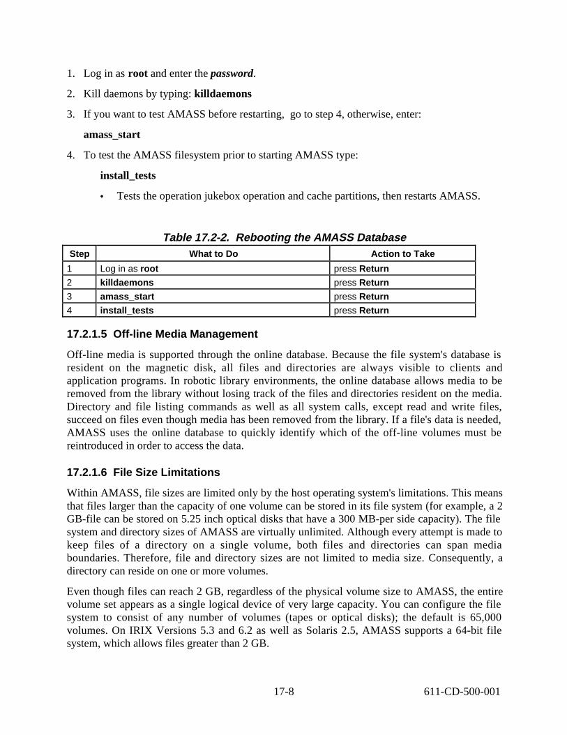
1. Log in as root and enter the password.
2. Kill daemons by typing: killdaemons
3. If you want to test AMASS before restarting, go to step 4, otherwise, enter:
amass_start
4. To test the AMASS filesystem prior to starting AMASS type:
install_tests
• Tests the operation jukebox operation and cache partitions, then restarts AMASS.
Table 17.2-2. Rebooting the AMASS Database Step What to Do Action to Take
1 Log in as root press Return
2 killdaemons press Return
3 amass_start press Return
4 install_tests press Return
17.2.1.5 Off-line Media Management
Off-line media is supported through the online database. Because the file system's database is resident on the magnetic disk, all files and directories are always visible to clients and application programs. In robotic library environments, the online database allows media to be removed from the library without losing track of the files and directories resident on the media. Directory and file listing commands as well as all system calls, except read and write files, succeed on files even though media has been removed from the library. If a file's data is needed, AMASS uses the online database to quickly identify which of the off-line volumes must be reintroduced in order to access the data.
17.2.1.6 File Size Limitations
Within AMASS, file sizes are limited only by the host operating system's limitations. This means that files larger than the capacity of one volume can be stored in its file system (for example, a 2 GB-file can be stored on 5.25 inch optical disks that have a 300 MB-per side capacity). The file system and directory sizes of AMASS are virtually unlimited. Although every attempt is made to keep files of a directory on a single volume, both files and directories can span media boundaries. Therefore, file and directory sizes are not limited to media size. Consequently, a directory can reside on one or more volumes.
Even though files can reach 2 GB, regardless of the physical volume size to AMASS, the entire volume set appears as a single logical device of very large capacity. You can configure the file system to consist of any number of volumes (tapes or optical disks); the default is 65,000 volumes. On IRIX Versions 5.3 and 6.2 as well as Solaris 2.5, AMASS supports a 64-bit file system, which allows files greater than 2 GB.
17-8 611-CD-500-001
17.2.2 Distributive AML Server (DAS)
AMASS supports mixed media in EMASS Automated Media Libraries (AMLs), using the DAS software on the Archive Management Unit (AMU). During the AMASS installation, unique media types are configured as if they were in separate libraries.
DAS is a COTS product with both client and server components. The server component is installed on the AMU OS/2 server, and the client component is embedded in AMASS. For DAS installation and operation on the AMU, refer to the DAS Installation and System Administration Guide. The DAS guide can be viewed using Adobe Acrobat and is available electronically on servers g0acg01 and g0acg05 in /usr/amass/books.
DAS is designed to provide shared access to the family of AMASS Automated Mixed-Media Libraries. An unlimited number of heterogeneous networked clients can be configured within a DAS environment. DAS provides customers with the ability to optimize their automation strategies, throughout the enterprise, and leverage their AML acquisition decision. DAS provides the ability to share AMLs with many clients.
DAS is integrated with backup, tape management and/or hierarchical storage management (HSM) applications on the client to direct automated removable media activity through the DAS server to the library. A DAS client may be any system requiring AML services. A client may be granted complete or restricted access to AML resources. AML resources are defined as drives, volumes and insert/eject areas and may be marked as shared or private to each client. Through client registration, the administrator function in DAS is able to control client access and privileges.
The DAS server component runs within the AMU on the AML. The DAS server converts client requests into complete AMU requests. It also creates journal entries of all requests, for recovery purposes, and sends request status back to the client. DAS may be installed as a standalone AML connection or be configured to share an AML with MVS or other, EMASS supported, host attachments.
17.2.3 Automated Cartridge System Library Software (ACSLS)
Storage Tek's UNIX-based ACSLS, allows applications based on the client systems access and manage information stored in an automated cartridge system (ACS). Client access appears as if the libraries were operating exclusively under the control of each client system. ACSLS performs library command processing on the client's behalf, as well as processing operator commands issued by the library system administrator. Library requests and messages move across a network which is a client-independent control path that connects client systems and the operator's console with the ACS.
ACSLS consists of a system administration component. The system administrator component provides an operator interface to control and monitor the ACS, including access control. A batch user interface allows automated scheduling of storage management functions, such as cartridge entry and eject, according to client processing requirements.
17-9 611-CD-500-001

A programmatic interface allows client applications to direct specific library service requests to the ACSLS. These service requests include cartridge mounts, dismounts, enters, and ejects. Additional requests allow client applications to determine and change the status of cartridges and ACS components.
Basic library management facilities of ACSLS includes command and message processing, maintenance of the contents and configuration data base, Cartridge Access Port (CAP) management, event log recording, scratch-pool management and access control.
ACSLS facilitates data security with administrator-assigned volumes and limited command access.
The centralization of operations support reduced storage management requirements and facilitates lights-out data center management. The FSMS supports multiple media. Table 17.2-3 identifies the different types of archive media used within the FSMS system. Archive media consist of tape and optical disk cartridges. Each tape or disk cartridge is identified by means of a bar code label that shows the media number. This number provides the means to produce an archive catalog that tracks the location of each cartridge within the library. The catalog numbering is based on information provided to the robot arm mounted laser bar code reading scanners.
Table 17.2-3. FSMS Media Types Media Media Purpose Archive
2.6 Gigabyte Optical Disk 9.4 Gigabyte Optical Disk
Archive Storage EMASS
50 Gigabyte D3 Tape Cartridge Archive Storage STK
17.3 Archive Configuration
The ability of the FSMS to absorb and to serve data at required rates depends on a well integrated, well tuned combination of high performance archival hardware and software. All the ECS DAACs have the same architecture and constituent components. The DAACs differ only in the size and particulars of equipment.
Figure 17.3-1, depicts the overall configuration for the STK main storage. For a representation of RAID attachment see Figures 17.3-2.
17-10 611-CD-500-001

ACSLS Storage TekSGI
A M A S S
S T M G T
ACSLS API
SCSI Device
D3
D3
D3
X8
5500 Tapes
50G/Tape
SCSI 1-8
20 MB/SEC
LibrayManagementUnitROBOT
SUN SPARC 5
ACSLS FDDI RS232
Figure 17.3-1. Archive Hardware and Software Configuration for STK
AMASS controls the physical storage of the data in the repository and is hosted on a SGI multiprocessor Challenge class server. The data collection resides in the STK Powderhorn robotic silo and is recorded using D3 helical scan tape drives from Storage Tek. SGI RAID is used for the temporary caching of data en route to and from the robotic silo.
As shown, the tape drives (D3) residing in the Storage Tek robotic silo are directly connected to the SGI Host via Fast-And-Wide SCSI II channels. Each channel is individually capable of the throughput of 20 MB/sec. Each of the eight tape drives is rated by the manufacturer capable of 11.2 MB/sec sustained throughput.
The control of the robotic mechanism of the silo (loading and unloading of the tapes) is affected via the STK ACSLS interface software running on a SPARC 5 SUN workstation. AMASS addresses the ACSLS through a network connection. ACSLS controls the robot directly via an RS232 line.
Figure 17.3-2, RAID Configuration, illustrates the configuration as of 8/19/97. The RAID level configuration is 3.
17-11 611-CD-500-001

6 CPUs
512 MB MAIN MEMORY, 2-WAY INTERLEAVED
32 KB DATA CACHE 1024 K STRIPE
18 RAID SCSI CONTROLLERS
20 MB/SEC
SGI CHALLENGE XL SGI SCSI RAID3 PHOENIX CONTROLLERS
SPA
SPB
20 MB/SEC
20 MB/SEC
20 MB/SEC
SPA SPB
9 GB
9 GB
9 GB
9 GB
SPA SPB
9 GB
9 GB
SPA SPB
9 GB
9 GB
9 GB 9 GB 9 GB
9 GB 9 GB 9 GB
9 GB
9 GB 9 GB 9 GB
9 GB
9 GB 9 GB 9 GB
9 GB 9 GB 9 GB
9 GB 9 GB 9 GB
9 GB 9 GB 9 GB 9 GB
20 MB/SEC
20 MB/SEC
20 MB/SEC
20 MB/SEC
Parity
Parity
Parity
Parity
Parity
Parity
Parity
Parity
Figure 17.3-2. RAID Configuration 8/19/97
Note
This configuration is the same for the EMASS browse system.
ECS browse capabilities depend on its ability to serve data to its users at required rates on a well integrated, well tuned combination of high performance archival hardware and software. Figure 17.3-3, depicts the overall configuration for the EMASS browse system. For a representation of RAID attachment see Figures 17.3-2.
17-12 611-CD-500-001

SGI
A M A S S
S T M G T
SCSI
DEVICE DRIVER OPTICAL
DISK
XDI INTERFACE
AMU IBM PS/2
0S/2 DAS
X6
OP DSK
OP DSK
ROBOT XXXX DISK
2.6/9.4 G DISK
RS232FDDI
SCSI 1-6
20 MB/SEC
EMASS
ROBOT CNTR
TOWER CNTR
EIF/IO CNT
Figure 17.3-3. Archive Hardware and Software Configuration for EMASS
AMASS controls the physical storage of the data in the browse unit and is hosted on a SGI multiprocessor Challenge class server. The data collection resides in the EMASS AML/2 and is recorded using a combination of optical disk drives, 2.6 Gigabyte and 9.4 Gigabyte, by Hewlard Packard and TBD. SGI RAID is used for the temporary caching of data en route to and from the AML.
As shown, the optical disk drives residing in the AML are directly connected to the SGI Host via Fast-And-Wide SCSI II channels. Each channel is individually capable of the throughput of 20 MB/sec. The 2.6 G drives are capable of 3.4MB per sec read and 1.7MB per sec writes with a 25 msec average seek time. The 9.4 G drives capabilities are not yet known.
The control of the robotic mechanism of the AML (loading and unloading of the disks) is effected via the GRAU DAS interface software running on a IBM PS/2 with OS/2. AMASS addresses the DAS through a network XDI interface connection. DAS controls the robot directly via an RS232 line.
17.4 Graphical User Interface (GUI)
Both custom and COTS software are supplied with a configurable X-Windows/Motif GUI interface. Many functions available on the command line can also be performed from the GUI.
17-13 611-CD-500-001

The GUI is configured by editing a button file. The System Administrator can comment out certain buttons, thus removing those functions from a user's GUI. The button file is then provided to the user and appropriate paths are set to locate the GUI interface button file and executables.
Data that are inserted into the archive can be received from a number of sources including the Ingest Subsystem, Processing Subsystem, other DAACs, and Authorized Users. The Data Ingest Technician (DIT) or other operators can monitor the insertion of data into the archive using the Data Server Subsystem (DSS) GUIs.
1. DDIST Graphical User Interface (GUI).
2. STMGT GUIs
The Activity Checklist depicted in Table 17.4-1 provides an overview of the Graphical User Interface section. Column one (Order) shows the order in which tasks should be accomplished. Column two (Role) lists the Role/Manager/Operator responsible for performing the task. Column three (Task) provides a brief explanation of the task. Column four (Section) provides the Procedure (P) section number or Instruction (I) section number where details for performing the task can be found.
Table 17.4-1. Graphical User Interface- Activity Checklist Order Role Task Section
1 DAM/DIT Graphical User Interface (I) 17.4
2 DAM/DIT Launching DSS GUIs Using UNIX Commands
(P) 17.4.1
3 DAM/DIT Storage Management Control GUI (I) 17.4.2
4 DAM/DIT AMASS GUI (P) 17.4.3
5 DAM/DIT AMASS GUI File Function (I) 17.4.3.1
6 DAM/DIT AMASS GUI Tasks Function (I) 17.4.3.2
7 DAM/DIT AMASS GUI Admin Function (I) 17.4.3.3
8 DAM/DIT AMASS GUI Preferences Function (I) 17.4.3.4
9 DAM/DIT AMASS GUI Help Function (I) 17.4.3.5
17.4.1 Launching DSS GUIs Using UNIX Commands
The following procedure demonstrates how to bring up a DSS GUI. It is expected that eventually the ECS DAAC desktop will be configured to allow access to the DDIST and other GUIs using icons. In the interim, access to the DSS GUIs must be gained through the use of UNIX commands. In any case, launching the GUIs starts with the assumption that the applicable servers are running and the operator has logged in. Table 17.4-2 presents the steps required to follow the procedure. If you are already familiar with the procedure, you may prefer to use this quick-step table. If you are new to the system, or have not performed this task recently, you should use the following detailed procedure:
17-14 611-CD-500-001

1. Access the command shell.
• The command shell prompt is displayed.
NOTE: Commands in Steps 2 through 12 are typed at a UNIX system prompt.
2. Type xhost + and then press the Enter key.
3. Start the log-in to the DDIST client server by typing either telnet hostname (e.g., g0dis02), rlogin hostname, or rsh hostname in the second window and then press the Enter key.
• If you use the telnet command, a Login: prompt appears; go to Step 5.
• If you use either the rlogin or rsh command, the system uses the User ID currently in use; go to Step 6.
4. When a login: prompt appears, log in as yourself by typing your UserID and then pressing the Enter key.
5. At the Password prompt type your Password and then press the Enter key.
6. Type setenv DISPLAY clientname:0.0 and then press the Enter key.
• Use either the terminal/workstation IP address or the machine-name for the clientname.
7. Type cd /path and then press the Enter key.
• Change directory to the directory path(e.g., /usr/ecs/mode/CUSTOM/utilities) containing the DSS command files (e.g., EcDsDdistGui).
• The mode will most likely be one of the following operating modes:
OPS (for normal operation).
TS1 (for testing).
TS2 (for other uses).
Note: the separate subdirectories under /usr/ecs apply to different operating modes.
8 . To launch the Data Distribution Requests GUI, type the following command: EcDsDdistGuiStart and then press the Enter key.
• The Data Distribution GUI is displayed.
9 . To launch the Storage Management Control GUI type the following command: EcDsStmgtGuiStart and then press the Enter key.
• The Storage Management Control GUI is displayed.
17-15 611-CD-500-001

1
2
3
4
5
6
7
8
Table 17.4-2. Launching DSS GUIs Using UNIX CommandsStep What to Do Action to Take
xhost press Return
telnet hostname press Return
UserID press Return
Password press Return
setenv DISPLAY clientname:0.0 press Return
cd /usr/ecs/mode/CUSTOM/utilities press Return
EcDsDdistGuiStart press Return
EcDsStmgtGuiStart press Return
17.4.2 Storage Management Control GUI
This tool enables operations to manage various data storage functions. These functions include the capability to set and modify configurations of various Server Types (e.g., 4mm tape, Archive Server, D3 tape), manage data location within the archive and on disk, configure stacker slots, display storage events which possibly require operator actions, and view backup/restore failures with the ability to restart a backup/restore operation. AMASS has to be up in order for the Storage management Tool to archive and retrieve files. Moreover the FTP server on the ACP host has to have debug logging enabled to write the filename of pulled files into the syslog for pull notification to the pull monitor.
The Tool is used to perform the following operator functions listed in Table 17.4-3.
17-16 611-CD-500-001

Table 17.4-3. Common ECS Operator Functions Performed with This ToolOperating Function
Command/Script or GUI
Description When and Why to Use
Configure Server Devices
Storage Config Tab Allows operators to organize and configure various Server Devices and manage data flow in and out of various archives.
As needed to add, delete, or modify the configuration of a set of Servers or a Server Device.
View the current cache statistics for the Pull Monitor cache.
Cache Stats. Tab Allows the operator to view the Pull Monitor cache and view the statistics on its use. Operator can delete expired files.
Used when warning is displayed in the message area informing the operator the cache is getting too full.
Search Event Log Storage Events Tab Allows operators to find events from selected parameters
As needed to locate events.
View current requests and manage tapes
Resource Schedule Tab
Allows operators to display the storage management view of the current requests
Used to select a specific request, manage tape group, stacker and slot configurations.
Storage Management Control can be operated from any one of the 4 tabs which control the 4 components as listed above (Table 17.4-3). The operator can select the following menu functions for each component tab from the menu bar items at the top of the window:
• File contains the exit command to close application
• Options allows operator to set the polling rate for the event log for the current execution of the application.
• Backup allows operator to set up data files as a backup at the operator site and at operator off-sites, to view backup files and to restart backup files.
• Setup allows operator to set up files for backup to on site or off site areas.
• Restart shows the location of failed files and provide a restart capability, see figure 4.10.2-14 (Restart Backup).
Menus named Selected, Edit , and View are also present at the top of the window, but functionality to be associated with them has not yet defined. They will be used in future releases.
For a detailed description of the Storage Management GUI, refer to the 609 document Section 4.10.2.
17-17 611-CD-500-001

17.4.3 AMASS GUI
Note
The AMASS GUI is a System Administrator tool, to be used only for monitoring the displayed information at this time. The GUI experiences intermittent problems known to the manufacturer and is due for complete functionality in a later software revisions 5.0.
The AMASS software provides DAAC Operations personnel with a GUI to access the functionality of AMASS utilities and command line functions.
AAWin (AMASS Administrator Window) provides the use of the AMASS GUI. This allows the menu functions of the GUI to become queries to the on-line index and facilitates the following functions:
• Assign and delete volumes.
• Modify volume characteristics.
• Modify volume groups.
• View volume/volume group usage statistics and monitor system performance.
• Reuse a volume.
The GUI performs a subset of the administration commands. The above tasks can be done with the AMASS administration commands, which are issued from the command line. Use the following procedure to start the AMASS GUI (AAWin). Table 17.4-4 presents the steps required reboot the AMASS database. If you are already familiar with the procedure, you may prefer to use this quick-step table. If you are new to the system, or have not performed this task recently, you should use the following detailed procedure:
1. Login as amass and enter the password.
2. Verify that AMASS is running.
At the prompt, type: amassstat -c
A message will display a message indicating the status of AMASS.
3. The GUI is accessible through the AMASS directory, /usr/amass/bin/. To start the AMASS GUI, type: aawin
Note: only one aawin session can be up at a time.
4. To exit, select the menu path: File/Exit
For a complete description of these commands, refer to the manual Managing the AMASS File System.
17-18 611-CD-500-001
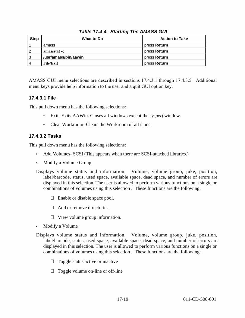
Table 17.4-4. Starting The AMASS GUIStep What to Do Action to Take
1 amass press Return
2 amassstat -c press Return
3 /usr/amass/bin/aawin press Return
4 File/Exit press Return
AMASS GUI menu selections are described in sections 17.4.3.1 through 17.4.3.5. Additional menu keys provide help information to the user and a quit GUI option key.
17.4.3.1 File
This pull down menu has the following selections:
• Exit- Exits AAWin. Closes all windows except the sysperf window.
• Clear Workroom- Clears the Workroom of all icons.
17.4.3.2 Tasks
This pull down menu has the following selections:
• Add Volumes- SCSI (This appears when there are SCSI-attached libraries.)
• Modify a Volume Group
Displays volume status and information. Volume, volume group, juke, position, label/barcode, status, used space, available space, dead space, and number of errors are displayed in this selection. The user is allowed to perform various functions on a single or combinations of volumes using this selection . These functions are the following:
⇒ Enable or disable space pool.
⇒ Add or remove directories.
⇒ View volume group information.
• Modify a Volume
Displays volume status and information. Volume, volume group, juke, position, label/barcode, status, used space, available space, dead space, and number of errors are displayed in this selection. The user is allowed to perform various functions on a single or combinations of volumes using this selection . These functions are the following:
⇒ Toggle status active or inactive
⇒ Toggle volume on-line or off-line
17-19 611-CD-500-001

⇒ Changing label
⇒ Delete volume
⇒ Introduce new volume to archive
⇒ Quick or normal formatting of volume
17.4.3.3 Admin
This pull down menu has the following selections:
• Scheduler - Opens the Scheduler Status Window.
• Sysperf - Opens the sysperf window displaying the AMASS I/O activity.
17.4.3.4 Preferences
This pull down window has the following selection:
• Show/Hide Detail Windows - These windows give a brief description of the items the mouse pointer is touching.
17.4.3.5 Help
• Opens the Help Window.
Detailed explanations of the GUI functions are located in the AMASS guide; Using the AMASS GUI. The AMASS guide can be viewed using Adobe Acrobat and is available electronically on servers g0drg01 and g0drg02 in /usr/amass/books.
17.5 Command Line Functions
Some but not all archive functions can be accomplished using a GUI. The operator should however become familiar with all command line utilities and commands. The following table provides a list of AMASS commands and utilities.
17-20 611-CD-500-001

Table 17.5-1. Common ECS Operator Functions Performed with AMASS (1 of 2)Operating Function
Command or GUI Description When and Why to Use
activate or
deactivate the
AMASS filesystem
• amassstat
• AA Win GUI displays or toggles the status
of AMASS
(ACTIVE/INACTIVE)
used to inactivate the filesystem for maintenance and/or to reactivate it
add a volume • volnew
• AA Win GUI
introduces a new volume to AMASS and assigns a volume number
to add storage space for data
add space to a volume group
• volnew
volgroup
• AA Win GUI
adds additional volumes to an existing volume group
when more space is required in an existing volume group
create a space pool
• volnew one or more volumes assigned to a special volume group of “SP”
to allow AMASS to automatically add space (volumes) to that has run out of space
create a volume group
• volgroup
setvolgrp
• AA Win GUI
partitions the volumes in
AMASS
to assign volumes for specific purposes within AMASS
delete a volume • volstat
voldelete
• AA Win GUI
removes a volume and its files from the archive
to delete a volume and any files
it contains
generate a report • amassreport generates formatted report and/or raw output
to extract information about files and directories from the AMASS index
back up the AMASS index
• amassbackup performs full or partial back up of the AMASS index
any time that the system needs
to be backed up other than what backup provides
put a drive into service
• drivelist
drivestat
• AA Win GUI
displays the current status of the drives and to change the status
when an INACTIVE drive is
ready to return to service
recover dead space
• volspace
volcomp
volformat
compresses a selected volume
to recover dead space on volumes
reinitialize the AMASS index
refer to the vendor documentation for the command and procedure
clears out the existing index and reinitializes it to an empty index
only when AMASS is not running
reintroduce an offline volume
• vollist
volslot
bulkinlet
volloc
reintroduces an offline volume to a jukebox
if data from an offline volume needs to referenced for read access
volume group
AMASSs automatic
17-21 611-CD-500-001

Table 17.5-1. Common ECS Operator Functions Performed with AMASS (2 of 2)Operating Function
Command or GUI Description When and Why to Use
Remove a volume or volume group
• vollist, voloutlet,
volloc
removes a volume or an entire volume group from the jukebox
to make room for new volumes or because data not being used needs to be retained
remove space from a volume group
• vgroot #VG
• setvolgrp /path #VG
• volgroup
removes space from one volume group to add it to another
when space is needed in another volume group
replace a full backup volume
• voloutlet 1,
• bulkinlet 0,
• vollabel {to rename}
• tapelength 1 2
• volformat -b 256k 1
• amassbackup -fv
initializes a new backup volume and performs a full backup
when the backup volume is 95% full
restore the AMASS database
• amassrestore restores the index either completely or to the point of the last full or partial backup
• when the index is corrupt on
the magnetic disk
• do not use the amassrestore command when AMASS is running
retrieve system usage by user
• amassreport displays the number of
files and directories owned by a user and the amount
of space they take up
to get statistical information on
the amount of space used by an individual(s)
retrieve system usage by volume
• adf displays volume group, jukebox reference number, position of volume, amount of used space, number of directories and files on volume, amount of free and dead space
to get statistical information
about the usage of a particular volume
reuse a volume • (volcomp, volstat, volclean, volformat
compresses and moves existing data to another volume, then reformats the volume
when a volume contains data no longer needed or contains mostly dead space
take a drive out of service
• drivelist, drivestat displays and changes the status of the drive
when a drive has excessive failures or for maintenance
For a full explanation of all AMASS commands see the AMASS System Administrator‘s Guide. The AMASS guide can be viewed using Adobe Acrobat and is available electronically on servers g0drg01 and g0drg02 in /usr/amass/books.
The Activity Checklist depicted in Table 17.5-2 provides an overview of the Command Line Fuctions section. Column one (Order) shows the order in which tasks should be accomplished. Column two (Role) lists the Role/Manager/Operator responsible for performing the task. Column three (Task) provides a brief explanation of the task. Column four (Section) provides
17-22 611-CD-500-001

the Procedure (P) section number or Instruction (I) section number where details for performing the task can be found.
Table 17.5-2. Command Line Functions - Activity ChecklistOrder Role Task Section
1 DAM/DIT Formatting a Volume (I) 17.5.1
2 DAM/DIT Formatting a Tape Volume (P) 17.5.1.1
3 DAM/DIT Formatting an Optical Disk Volume (P) 17.5.1.2
17.5.1 Formatting a Volume
To format a volume, it must be online. A volume is placed online using the volloc command. If the volume is a tape cartridge, you must first set the tape length using the tapelength command. Formatting a volume will destroy any files on that volume. Before formatting a volume, check to make sure it does not have any files which should be saved. Tables 17.5-3 and Table 17.5-4 present the steps required to follow the formatting process. If you are already familiar with the procedure, you may prefer to use this quick-step table. If you are new to the system, or have not performed this task recently, you should use the following detailed procedure:
17.5.1.1 Formatting a Tape Volume 1. Put the volume online using the following command:
volloc -n volnumber • volnumber is the number of the volume
2. Verify there are no files on volume. volfilelist volnumber
3. Set the tape length. Tapelength 2 volnumber • 2 is the value used to set tape length for 50G tape. • volnumber is the number of the volume
4. Format the volume. volformat -b 262144 volnumber
5. Verify status of the volume volprint -a volnumber
17-23 611-CD-500-001

Table 17.5-3. Formatting a Tape VolumeStep What to Do Action to Take
1 volloc -n volnumber press Return
2 volfilelist volnumber press Return
3 Tapelength 2 volnumber press Return
4 volformat -b 262144 volnumber press Return
5 volprint -a volnumber press Return
17.5.1.2 Formatting an Optical Disk Volume 1. Put the volume online using the following command:
volloc -n volnumber • volnumber is the number of the volume
2. Verify there are no files on volume. volfilelist volnumber
3. Format the volume. volformat -b 1024 volnumber
4. Verify status of the volume volprint -a volnumber
Table 17.5-4. Formatting an Optical Disk Volume Step What to Do Action to Take
1 volloc -n volnumber press Return
2 volfilelist volnumber press Return
3 volformat -b 1024 volnumber press Return
4 volprint -a volnumber press Return
17.6 Storing New Data in Archive Repository
Storing new data in the archive repository is largely an automated process that does not normally require operator interaction and occurs as a result of operations such as ingest and data production. Any operations involvement would be to support archive administration operations, resolve problems, periodically monitor working storage and archival operations, and coordinate with the appropriate external/internal sources to resolve schedule conflicts.
Because of the automated nature of this process, step-by-step procedures are not required however, a typical archive scenario is shown.
Insert Data into the Archive Scenario
17-24 611-CD-500-001

NOTE: The scenario that follows describes the insertion of data into the Data Server at an ECS DAAC and is derived from document 605-CD-002-001, Release B SDPS/CSMS Operations Scenarios for the ECS Project (March 1996).
Data and associated metadata can be received from numerous sources. This scenario focuses on a routine data insert from the Science Data Processing subsystem. It assumes that all components are active and not in any degraded modes of operation, that ESDT data collection types have been established, and that the data server’s nominal activity rate is 50% of capacity.
Initiate the session between the Processing Subsystem and the Data Server.
The Processing Subsystem sends a Data Insert Request to the Science Data Server.
Receipt of the request is logged (via MSS Logging Services) and a request identifier is associated with the Data Insert Request.
The content of the request is validated; if successful, it is queued for later processing. If unsuccessful, a rejection message is issued.
The operator may examine the progress of a request by following menu path Other Screens→Logs & Reports (MSS). In the Data Server Subsystem, open Storage Manager (DSS-OSM) to browse the log files provided by the Management Services Subsystem (MSS); see next section for details.
Transfer data from Processing Subsystem to Data Server.
The queued Data Insert Request is reached and processing begins.
Associated data granules and metadata are transferred from the Processing Subsystem to the Data Server working storage.
Data transfer status, including recoverable errors, are indicated in the event log via MSS Logging Services.
The operator may check request status at any time using the DSS-OSM Request Screen.
Validate metadata received from the Processing Subsystem.
The metadata update file(s) produced by the associated product PGEs are validated for completeness and correctness.
Validation success or failure is logged via MSS Logging Services with the associated Data Insert Request Identifier and the appropriate status message is returned to the Processing Subsystem.
Store data granules in the permanent archive.
Upon successful validation of the metadata update file, Science Data Server sends a Data Storage Request to Storage Management.
The data granules in working storage associated with the Data Storage Request are stored.
17-25 611-CD-500-001

The Archive Activity Log (via MSS Logging Services) records each data product being stored and storage status of each storage operation.
A checksum value is calculated for each data object associated with each granule.
The checksum value, storage status, and other selected metadata are forwarded to the Science Data Server in a status message upon completion of the Data Storage Request.
Store metadata.
Science Data Server receives and logs the Data Storage Request status message from Storage Management.
The additional metadata items are validated.
The PGE produced metadata update file and the storage management provided metadata are loaded into the metadata database.
The status of the metadata load is entered in the event log.
The operator may examine the progress of the insert by following menu path Other Screens→Logs & Reports (MSS) in the DSS-OSM to browse the log files provided by the MSS.
Report Data Insert Request status.
The Science Data Server logs completion of the Data Insert Request in the event log and reports completion of the Data Insert Request to the Data Archive Manager, the operator console and to the insert Requester (the Processing Subsystem in this scenario).
Each of the above entities would also be notified if the request failed and reason(s) for failure identified.
Process subscriptions based on newly inserted data.
The Science Data Server will then examine the event list for all subscriptions for that event.
Subscription notifications are sent to the appropriate entities as appropriate and distribution processing is initiated.
The Science Data Server sends an Advertisement Update Message to the Advertising Server to advertise the new data.
17.6.1 Monitor Insertion of Data into the Archive
Data that is inserted into the archive can be received from a number of sources including the Ingest Subsystem, Science Data Processing Subsystem, other DAACs, and Authorized Users. The DIT can monitor the insertion of data into the archive using the Ingest GUI or, by going to the appropriate server (e.g. g0drg01) following archive directory and doing a list: /dss_stk1/mode/datatype where mode is the operating mode i.e. TS1, TS2, SHARED or, OPS and datatype is the type of data being archived, i.e. aster or modis. For detailed information on the functionality of these GUIs, review the 609 User’s Guide document.
17-26 611-CD-500-001

17.6.2 Monitor Insertion of Data into the Archive using AMASS
AMASS provides a capability to monitor the system with a number of commands. Table 17.6-1 provides a list of helpful AMASS software commands that may be used to monitor insertion of data into the FSMS system. These commands are accessible through the /usr/amass/bin directory.
Table 17.6-1. AMASS Monitoring Commands amassstat _view or toggle AMASS status
dirfilelist _view subdirectories or files under a directory
drivelist _Listing and status of the drives.
jobs _displays jobs pending and status of jobs completed
quedisplay _displays request in the que and volumes allocated to the drives
sysperf _system through put and individual drive data rate performance, drive status, and volume mounts
vglist _view attributes for a volume group
vgroot _view relative path for a volume group
volstat _view status (active or inactive) or, change status of a volume
volusage _view statistics for all volumes
vollist _Listing and status of the volumes in library.
volspace _view volumes with a specified percentage of dead space
The AMASS GUI is available for the DAM to view drive, file, file system, volume, and juke box statuses. The GUI is to be used for monitoring only. All drive juke, file or volume changes should be done through command line operations. The GUI is accessible through the AMASS directory, /usr/amass/bin/gui.
17.6.3 Monitor Archive Status Using ACSLS
ACSLS provides the capability to monitor the Storagetek portion of the FSMS system. Although ACSLS does not keep track of data files, equipment and media status may indicate any problems in accessing the data. Table 17.6-2 provides a list of ACSLS software commands that are useful in monitoring the system. These are query commands that can be used to status specific items, or all in the category specified. These commands are accessed through the command procedure shell window of the ACSLS workstation.
17-27 611-CD-500-001

Table 17.6-2. ACSLS Monitoring Commands query server all _display status of all servers
query request all _display status of all request
query volume all _display status of all volumes
query drives all _display status of all drives
query lsm all _display status of all lsms
query cap all _display status of all caps
query acs all _display status of all acs
query port all _display status of all ports
17.6.4 Monitor Insertion of Data into the Archive using DAS
DAS provides the capability to monitor the status of the EMASS portion of the FSMS system. Table 17.6-3 provides a list of DAS Administration commands that are useful in monitoring the system. These are query commands that can be used to status specific items, or all in the category specified. These commands are accessed through the command procedure shell window of the DAS workstation or from the PC located on the AML.
Table 17.6-3. DAS Monitoring Commands list _requests DAS to list currently
active requests
view _displays the status of a volume
listd _display status of drives
robstat _display or change status of robot
qvolsrange _display list of accessible volumes within the specifies range
17.6.5 Fault Notification
The fault notification process in the archive begins with an error condition arising with software, hardware, or data related faults. The problem notification between the DIT and the DAM will most likely be verbal, although electronic notification may be necessary at times.
The DAM or DIT will use the trouble ticket system available on site to officially notify the DAAC of warranted archive problems. The trouble ticketing procedures are found in the Problem Resolution section of the DID 611 document (section 8). The DAM or DIT may notify appropriate DAAC personnel while still in the error evaluation mode and before the trouble ticket creation process. This stipulation allows for the timely notification process to begin before an official document is issued. Table 17.6-4 presents the steps required to follow the fault notification process. If you are already familiar with the fault notification procedures, you may prefer to use this quick-step table. If you are new to the system, or have not performed this task recently, you should use the following detailed procedure:
17-28 611-CD-500-001

1. Identify problem with the ingest, archive, or data distribution subsystems.
2. Investigate error messages or problem indications.
3. Notify DAM of problem via person, phone, or electronic means.
4. DAM identifies and evaluates severity of problem. DAM must determine downtime and production impact, if any. Some problems may require a software reboot or simply putting damaged hardware off-line and continuing until servicing is possible.
5. DAM investigates error messages or problem indications: software, hardware, data related.
6. Evaluation should determine if the problem is repairable or if repair requires attention of the specified maintenance contractor.
7. Solve problem if possible.
8. Notify personnel deemed necessary if severity warrants via phone, in person or by electronic means (optional step). Some circumstances deemed severe enough may require notifications to DAAC staff in evaluation stage before a trouble ticket is created. This does not circumvent the trouble ticket process. It only allows for the repair effort process to start without addition downtime awaiting official notices.
9. Create Trouble Ticket.
10. DIT/ DAM officially notify DAAC of a problem and severity with a trouble ticket.
11. Notify service personnel required to repair problem if appropriate.
Table 17.6-4. Fault Notification-Quick-Step Procedure Step What to Do Action to Take
1 DAM or DIT Identify problem with the archive system investigate error messages or problem indications
2 DAM notified of problem oral, phone or electronic notification
3 DAM identifies and evaluates severity of problem investigate error messages or problem indications: software, hardware, data related
4 Repair problem in timely manner if possible Solve problem if possible
5 Notify personnel deemed necessary if severity warrants (optional step)
oral, phone or electronic notification
6 DIT/ DAM officially notify DAAC of a problem and severity
Create Trouble Ticket in Remedy and or DDTS
7 Notify service personnel required to repair problem if appropriate.
Notify appropriate personnel
17-29 611-CD-500-001

17.6.6 Recovery from Failure to Store or Retrieve Data
When a storage failure occurs, the request is failed and the reason for failure is returned to SDSRV. The Storage Management Control GUI as well as AMASS commands and utilities permit the operator (e.g., Data Ingest Technician) to review the error messages. The operator can also monitor system tail logs in UNIX windows in order to track storage activity. For AMASS based archives, the most likely cause of a failure will be file copy errors due to network problems, mount point problems, AMASS being down, or failure to associate a volume group with a directory in the AMASS cache. AMASS will not report write errors even if all of the drives are off-line. Only when there is no media in AMASS will a write error be reported. Table 17.6-5 presents the steps required to follow the fault notification process. If you are already familiar with the procedure, you may prefer to use this quick-step table. If you are new to the system, or have not performed this task recently, you should use the following detailed procedure: 1. Login as amass or root and enter the password
• Remember that your password is case sensitive.
2. Use the amassstat command to determine if AMASS is running.
3. Use the amass_log script and SYSLOG to display AMASS errors.
• The amass_log script is located in the /usr/amass/tools directory.
• The SYSLOG is located in the /var/adm/ directory. It may be necessary for the operator to look at the syslog on the host where the file is located to see if there are error messages which may explain the failure to access a file.
• Each AMASS entry in the system log file has a date and time stamp. Several days‘ worth of messages may exist in the log. When reviewing the output to determine if any of these messages might indicate the cause of the problem, make sure that the messages being looked at are for the correct date and time.
4. See the “Error Messages” in the appendix of the AMASS System Administrator’s Guide, Version 4.9, for probable causes and possible solution to the problem. The AMASS document can be viewed using Adobe Acrobat and is available electronically on servers g0drg01 and g0drg02 in /usr/amass/books.
5. After the corrective action has been performed, see if the problem is corrected.
6. If the problem persists further problem diagnosis should be attempted starting with the procedures below in sections 17.6.6.1 (Write errors) or 17.6.6.2 (Read errors).
17-30 611-CD-500-001

Table 17.6-5. Recovery from Failure to Store or Retrieve Data Quick-Step Step What to Do Action to Take
1 amass or root press Enter
2 amassstat press Enter
3 amass_log press Enter
4 Correct the problem
5 Verify correction
17.6.6.1 Diagnoses and Investigation of Write Errors
Write errors to the archive should be infrequent. If the archive is a robotic library which is fronted by the AMASS software, error messages in /var/adm/syslog will show the error messages from the AMASS software. If the archive is a disk based archive, then the software will receive the write errors and report them via operator notification and MSS error logging.
17.6.6.1.1 Causes of Write Errors
With AMASS
AMASS off-line - software will capture the error and log this since the directory that is being written to will not exist. However, the nature of the write error will not be detected.
All Drives off-line - Cache space will fill up, write requests will be accepted but, all new data sent to cache will not be captured. The data transfer requests hang and do not return an error. Current code does not allow for detection of this condition. Write requests to AMASS can not be killed. The operator will have to diagnose this condition after being notified by Tivoli that AMASS drives are off-line or by noticing problems while looking at the log files.
No media associated with the directory - will cause a write error which is detectable by the software. The nature of the error will not be detected.
Without AMASS:
Disk Partition Filled up - software will capture this condition although the error condition will not be known.
With or without AMASS
Directory does not exist - will cause a write error
Undetected write errors
AMASS: media write failure - will cause the drive to go off-line and the media volume to go offline as well. The error will be written to /var/adm/syslog. No error will be detected by the application software. The operator can execute a /usr/amass/bin/drivelist to see which drive has been put off-line.
17-31 611-CD-500-001

17.6.6.2 Diagnoses and Investigation of Read Errors
When a read error is encountered by AMASS, both the drive and the tape will be taken off-line. The application will be notified of the read failure. The Archive Server will log an error message when the read failure is returned. The log message will include the name of the file, the secondary path for the file, the checksum for the file, and a reason for the failure. If the reason for failure is a checksum mismatch on retrieval, then the file will have to be restored. If the reason for failure indicates the media was off-line, then further investigation will have to take place to determine why the tape was off-line. This could be the result of a write error, a read error on the file, or a read error on a another file that caused AMASS to take the tape off-line. For a tape that is off-line, visual inspection or more likely, the need to have vendor maintenance remove the media from the drive, will indicate that a tape is damaged. Any requests for files on that tape will fail or be served from backup. It will be important that the list of files that will be created for restoring a tape from backup be kept and searched when new files are reported missing. This should reduce the number of times that certain procedures have to be performed.
This operations concept builds on the operations concept for reviewing a read error in the first case, and the concept of determining which file was damaged in a situation where data has been recovered from damaged tape.
17.6.6.2.1 File was not successfully retrieved
1. The operator will be notified of Retrieval errors on the STMGT GUI (NCR 16497), the reason for the failure, and the file path for which the file was accessed.
2. The operator will use the path and filename to get the volume id by using the AMASS command fileprint fullpathname.
3. Once the tape is found, then a vollist given the volume id will indicate the state of the tape. If the tape is not active, then investigation using the AMASS logs will have to be done to determine if there was a drive error on the read which took the tape and a drive off-line. If the tape is on-line then the operator will have to determine the cause of the read error from the STMGT GUI.
4. The Operator must now decide whether the effected tape is still useable or not:
• In the event that the tape appears not to be physically damaged and only a small number of files on the tape have reported read failures recovery of those files alone can be attempted. This should use the procedure “Data Recovery Procedure for Known Files” in section 17.9.2.2. A small number of files from more than one tape may also be handled together at this stage.
• Alternatively if the tape is visibly damaged or is suffering multiple read failures recovery of the entire tape can be attempted. This should use the procedure “Data Recovery Procedure for an Entire Tape” in section 17.9.2.1.
17-32 611-CD-500-001

17.6.7 Deleting Files From the Archive using the AMASS GUI
Deleting files from the archive can be an automated process, with a window provided to show files available for deletion based on system requirements. The AMASS GUI provides a window that allows file deletions. For detailed instructions see AMASS document Using The AMASS GUI.
17.7 Archive Backup
AMASS gives you the ability to manage archive and backup applications from a variety of hosts on the network using one or more protocols and any backup solution that can write disk files, for example, tar or cpio.
Because the online AMASS database is the database to the media contents of an AMASS volume set, it must be protected. AMASS provides an automated procedure to back up the database to a dedicated volume in the library. The backup process supports both full and partial backups and can be run either automatically by AMASS or manually by the system administrator. However, for standalone drives you must manually backup the database. Text to insert in 17.7/17.6.6:
Archive data recovery and restoration requirements create backup tapes for storage at local as well as designated remote sites. The arrangement eliminates a single point of failure in data recovery and restoration for the individual DAACs.
Operational staff create these tapes at regular intervals by the using manual commands or automated scripts. The backup procedure creates a tape for local storage in the archive and onsite. The second backup transfers to tape for shipping or to a temporary file for transmit to the designated off-site storage location.
GDAAC sends its backup data to a location at Goddard, but separate from the GDAAC.
Backup data stores that data that which would be hard to reproduce if needed. This data includes the following types: ancillary, metadata, algorithms, engineering, calibration, systems and application software, and selected other data depending on need.
Because the above recovery functions are automated and can be executed from the startup script upon system reboot, the AMASS recovery, startup, and file system mount can all be done in the same fashion as the handling of other UNIX file systems.
Archive data backup is largely an automated process. Automatic and manual backup and restore operations ensure data integrity and safety. Backups are called on automatically to satisfy Read requests where the Read from Primary has failed. As a clarification of terms, backup is used in two contexts.
The first context involves a fully automated process and is set up by the System Administrator via a cron job. This process backs up the AMASS database with options, full (File System Index and Journal Files) or partial (Journal Files only) database backup. This same process can also be duplicated using a AMASS software command. This process backs up the AMASS database at
17-33 611-CD-500-001

the operators convenience or when necessary for performing maintenance or troubleshooting on the system.
A second context of backup pertains to the backup of actual archive data. This data is selected for backup by the severity of efforts to recover in event of its loss. This data is saved in the archive, saved to a local site, and saved to a remote site. This replication is essential to data safety.
The actual data backup is performed with the custom software provided or by manual operations. The custom software automatically backs up selected data types. Configured software will transfer the backup data simultaneously with the actual data transfer to the archive parent volume or store the data in cache for a later transfer to backup volumes.
The Activity Checklist depicted in Table 17.7-1 provides an overview of archive data backups. Column one (Order) shows the order in which tasks should be accomplished. Column two (Role) lists the Role/Manager/Operator responsible for performing the task. Column three (Task) provides a brief explanation of the task. Column four (Section) provides the Procedure (P) section number or Instruction (I) section number where details for performing the task can be found.
Table 17.7-1. Archive Data Backup- Activity Checklist Order Role Task Section
1 DAM/DIT/SA AMASS Database Backup (I) 17.7.1
2 System Administrator (SA)
AMASS Automated Backup (I) 17.7.1.1
3 DAM/SA AMASS Manual Backup (P) 17.7.1.2
4 DAM/SA AMASS Database Manual Restore (P) 17.7.1.3
5 DAM/SA ACSLS Database Backup and Restore (P) 17.7.2
6 DAM Backing Up Archive Data (I) 17.7.3
7 DAM Generate List of Data to be Backed Up (P) 17.7.3.1
8 DAM/SA Creating Local Backup Tapes (P) 17.7.3.2
9 DAM/SA Creating Off-Site Backup Tapes (P) 17.7.3.3
17.7.1 AMASS Database Backup
AMASS software provides two backup procedures. One, fully automated, performs a full backup on the first day of each month along with selectable full or incremental backups at regular intervals set by the system administrator. The current setup initiates a partial backup every evening at 2 a.m. A selection of a full backup involves Journal and File System Index files. The second procedure is partial backup involving only Journal files.
17-34 611-CD-500-001

The AMASS software also provides a manually performed backup procedure, amassbackup that performs the same functions as the automated backup except with manual intervention.
17.7.1.1 AMASS Automated Backup
The online database of AMASS needs protection. It is the index to the media contents of the AMASS volume sets. This procedure performs automatically without outside intervention. The Systems Administrator can modify the frequency of these backups and add partial backups for another time by changing the cron job which initiates the backup.
17.7.1.2 AMASS Manual Backup
This second procedure involves logging into AMASS and commanding the backup script, amassbackup, which utilizes either full or partial options. This command also includes capability to transfer to a tape device or to a designated archive volume. Since the system performs the automated backup without intervention, only the second procedure is be described below.
This backup procedure utilizes a backup volume or tape device. Please note that both methods only back up the File System Index and Journal files. If you are already familiar with the procedures, you may prefer to use the quick-step table. If you are new to the system, or have not performed this task recently, you should use the following detailed procedure:
1. At the UNIX prompt, type amass or root and enter the password.
• Logs you into AMASS
2. Enter AMASS command:
amassbackup [-fv]
Table 17.7-2. AMASS Backup Command-Quick-Step Procedure Step What to Enter or Select Action to Take
1 amass or root press Return
2 amassbackup [-fuv] [-d tapedevice] press Return
Further explanation of the command is found in the AMASS System Administraors Guide. The AMASS guide can be viewed using Adobe Acrobat and is available electronically on servers g0drg01 and g0drg02 in /usr/amass/books.
17.7.1.3 AMASS Database Manual Restore
Restoring the AMASS database is a manual process which must be initiated by either the System Administrator or, the DAM. The AMASS database is restored using the AMASS command, amassrestore. The amassrestore command will restore the last full backup, the last partial backup
17-35 611-CD-500-001

and all journal transactions that occurred since the last backup. Upon execution, the amassrestore command will create a sub-directory under filesysdb called journal. All restored files will be copied to the journal directory.
This restore procedure utilizes a backup volume or tape device. Please note that both methods only restore the File System Index and Journal files. If you are already familiar with the procedures, you may prefer to use the quick-step table. If you are new to the system, or have not performed this task recently, you should use the following detailed procedure:
1. At the UNIX prompt, type amass or root and enter the password.
• Logs you into AMASS
2. Enter AMASS command:
amassrestore [-fuv]
Table 17.7-3. AMASS Backup Command-Quick-Step Procedure Step What to Enter or Select Action to Take
1 amass or root press Return
2 amassbackup [-fuv] press Return
Further explanation of the command is found in the AMASS System Administrators Guide. The AMASS guide can be viewed using Adobe Acrobat and is available electronically on servers g0drg01 and g0drg02 in /usr/amass/books.
17.7.2 ACSLS Database Backup and Restore
The ACSLS databases are located on disk on SUN workstations; each library silo having it‘s own dedicated SUN. ACSLS provides a script to perform its database backup. This script is run from the ACSSA cmd_proc window. The ACSLS database should be backed up periodically. StorageTek recommends that you use bdb.acsss to back up the database to tape after any of the following conditions:
• Running acsss config
• Importing or converting the database.
• A significant number of enters or ejects.
• A large number of scratch mounts.
• A significant number of volume state changes, such as from scratch to data or from
locked to unlocked.
• Any database recovery.
17-36 611-CD-500-001

You can only use backups created by bdb.acsss to restore the ACSLS database and you must use rdb.acsss to restore it. Similarly, you can only use the db_export.sh, and db_convert.sh database utilities to export, and convert/import, the ACSLS database. For more information on exporting and converting the ACSLS database refer to the ACSLS Installation and Configuration Guide.
To ensure that you recover an accurate and consistent database, always use the most current database backup.
After you upgrade to a new version of ACSLS, do not use database backups or exports created with previous versions. Make sure, however, to create a new backup as soon as you have upgraded.
Use the bdb.acsss utility to back up the ACSLS database.
When the server disk that contains the database reaches a predefined limit, ACSLS automatically creates a checkpoint backup file to disk. You should also, however, periodically run the bdb.acsss utility to manually create checkpoint files (especially to create tape backups that can be stored offsite). During ACSLS operations, transactions with the library create redo log files. Table 17.7-2 describes the database checkpoint and redo log files. If the database fails, you can recover the database using the rdb.acsss utility. Retain all utility event logs. These logs will help StorageTek to resolve any problems.
Table 17.7-3. Checkpoint and redo log files. File Type Definition and Use
checkpoint files Provides a point-in-time snapshot copy of
the entire database
redo log files Transaction records of database changes made since the last checkpoint. During database recovery using rdb.acsss, these files are applied sequentially to the checkpoint to re-create the database including all transactions since the checkpoint.
17.7.2.1 ACSLS Database Backup Script
If you are already familiar with the procedures, you may prefer to use the quick-step table. If you are new to the system, or have not performed this task recently, you should use the following detailed procedure:
1. Log in as acsss and enter the password.
• Logs you into acsss
17-37 611-CD-500-001

2. Load tape into backup drive.
3. If you enter bdb.acsss with no options, the backup utility defaults to the default tape device attached and configured to the ACSLS server. At acssa prompt, enter:
• bdb.acsss
• The bdb.acsss utility backs up the ACSLS database and miscellaneous library resource files.
4. For backup to a specific drive or file; enter the utility and options:
_ bdb.acsss [-f filename or tape~device] [-o]
• -f tape_device
specifies any tape device attached and configured to the ACSLS server.
• -f filename
specifies a UNIX file to contain the ACSLS database. You must have write permissions to the file.
• -0 is ignored; provided for compatibility with previous 11 ACSLS versions.
Table 17.7-4. Create ACSLS Back Up - Quick-Step Procedures Step What to Enter or Select Action to Take
1 acsss press Return
2 bdb.acsss [-f db_file I tape~device] [-o] press Return
17.7.2.2 ACSLS Database Restore Script
ACSLS provides the rdb.acsss utility to restore the database in case of severe disk or data problems. Provided you have made regular backups, you should be able to restore the database with little or no loss of data. It will probably be necessary to restore the database in any of the following situations:
• After a system crash.
• Anytime the database can not be started.
• Anytime there is a physical or logical error in the database.
17-38 611-CD-500-001

If you are already familiar with the procedures, you may prefer to use the quick-step table. If you are new to the system, or have not performed this task recently, you should use the following detailed procedure:
1. Log in as acsss and enter the password.
• Logs you into acsss
2. Load the restore tape into backup drive.
3. If you enter bdb.acsss with no options, the backup utility defaults to the default tape device attached and configured to the ACSLS server. At acssa prompt, enter:
rdb.acsss
• The rdb.acsss utility restores the ACSLS database and miscellaneous library resource files.
4. To restore from a specific drive or file; enter the utility and options:
rdb.acsss [-f filename or tape~device] [-o]
• -f tape_device
specifies any tape device attached and configured to the ACSLS server.
• -f filename
specifies a UNIX file to contain the ACSLS database. You must have read permissions to the file.
• -0 is ignored; provided for compatibility with previous 11 ACSLS versions.
Table 17.7-5. Create ACSLS Restore - Quick-Step Procedures Step What to Enter or Select Action to Take
1 acsss press Return
2 rdb.acsss [-f db_file I tape~device] [-o] press Return
17.7.3 Backing Up Archive Data
During normal operations, data will be backed up automatically to volume groups according to parameters set in the ESDT. When an ESDT is loaded into the system, part of the information that is given is the Archive Id, Backup Archive Id, and off-site id. The Archive Id and Backup Archive Id dictate where the file will be stored for the primary and backup copies. Backup Archive Id and off-site id may be empty strings, in which case no backup is done.
The Archive Id and Backup Archive Id are both comprised of two parts: the server key and the logical volume group indicator. The server key is used by the code to attach to the correct archive server when data for the ESDT is ingested or acquired. The logical volume group
17-39 611-CD-500-001

indicator is used by the archive server to write the file to the correct volume group in the archive. The off-site id is a three character id of the DAAC which is doing off-site storage for that ESDT. The software supports having the three character designation for the local DAAC be the off-site id. In this case, the file will be backed up to a volume group within the local archive. The STMGT operations GUI can be used to get information about the pathnames in AMASS that map to the different logical volume group identifiers. Logical volume group identifiers are also configured via the GUI.
For various reasons however, it may be necessary to manually backup data. To backup specific data, the DAAC Archive Manager (DAM) will generate or will have generated for him/her a list of data types which are designated for local or off-site backup. At the time the files are archived they are written to specific volume groups which correspond to the specific data type(s). Only files belonging to the data type are written to the tapes in a specific volume group. Hence, by knowing which data types are designated for backup, the DAM can determine the tapes which should be backed up locally and for off-site storage. This can be accomplished using the AMASS administration vollist command. The DAM can determine how many tapes must be backed up by using this command.
If there are other files designated for local and off-site backup which have not been written to a specific volume group, the DAM can use the appropriate AMASS administration commands, dirfilelist and/or volfilelist, to locate the appropriate archive volume which contains the designated archived files.
For more information about these AMASS commands, refer to the AMASS System Administrators Guide. The AMASS guide can be viewed using Adobe Acrobat and is available electronically on servers g0drg01 and g0drg02 in /usr/amass/books.
17.7.3.1 Generate List of Data to be Backed Up
Certain volume groups are dedicated for storing backup data. Using the AMASS administration commands and UNIX utilities, the DAM generates a sorted list of files contained on each volume in a backup volume group. It is important to sort the list by volume number to minimize the number of volume mounts and dismounts. The sorted list is edited to remove files which are not desired to be backed up.
Table 17.7-6 presents the steps required to generate a list of data to be backed up. If you are already familiar with the procedures, you may prefer to use this quick-step table. If you are new to the system, or have not performed this task recently, you should use the following detailed procedure:
1. At the UNIX prompt, type; amass or root and enter the password.
• Logs you into AMASS.
17-40 611-CD-500-001

2. To generate a list of all files on a backup directory type: dirfilelist pathname • pathname is the path of the backup directory i.e., /dss_stk2/modis/backup.
3. To generate a list of the files on each volume, type: volfilelist volumenumber
• The volume numbers used should be the ones designated for data backup.
Table 17.7-6. Generate List of Data to be Backed Up - Quick-Step Procedures Step What to Enter or Select Action to Take
1 amass or root press Return
2 vollist press Return
3 volfilelist volumenumber press Return
17.7.3.2 Creating AMASS Local Backup Tapes
Using the output from section 17.7.3.1 as input, create local backup tapes using the appropriate UNIX commands to copy all of the files to a designated volume group. After creation of the backup tapes, remove the tapes from the AML if required.
Although some backup volumes may be stored locally external to the Powderhorn LSM, most will be stored within a library silo. Table 17.7-7 presents the steps required to create a volume group to be used for the creation of local backup tapes. If you are already familiar with the procedures, you may prefer to use this quick-step table. If you are new to the system, or have not performed this task recently, you should use the following detailed procedure:
1. At the UNIX prompt, type; amass or root and enter the password.
• Logs you into AMASS.
2. Create the subdirectory (if not already created) by entering the following: a) mkdir /dss_stk1/vg22/local_backup/
• The directory above is only an example, actual directory structure is determined by the System Administrator.
b) Press Return.
3. Create a volume group and associate it with the subdirectory just created by typing: setvolgrp path volumegroup
• Path is the full UNIX system path name of the directory whose directory tree is being assigned to the volume group.
17-41 611-CD-500-001

• Volumegroup is a number between 0 and 2047 assigned to the volumes by the volgroup command.
• Ex. setvolgrp /dss_stk1/vg22/local_backup 22
4. The operator goes to the Configure tab in the STMGT GUI and selects the appropriate archive server.
5. The operator then selects Add Volume Group and enters in the volume group identifier and the path for the volume group.
6. The operator then selects Backup from the pull down menu at the top of the STMGT GUI and selects Setup.
7. The operator sets the site id to be the three character specification for the local site.
8. The operator has to then go into the STMGT database and update the off-site table with the volume group name that was created to hold the data that needs to be backed up for off-site storage. (GUI doesn‘t cover this yet, see System Administrator for help).
9. Add tape volumes to the volume group as needed using the volgroup command or, enable the space pool for that volume group with the vgpool command.
• For more information on using AMASS commands, see AMASS System Administrator‘s User Guide. The AMASS guide can be viewed using Adobe Acrobat and is available electronically on servers g0drg01 and g0drg02 in /usr/amass/books.
Table 17.7-7. Create Local Back Up - Quick-Step Procedures Step What to Enter or Select Action to Take
1 amass or root press Return
2 mkdir /dss_stk1/vg22/local_backup/ press Return
3 setvolgrp path volumegroup press Return
4 cp filename pathname press Return
5 ADD volume group enter volume group identifier
6 Select Backup/Setup
7 Set id to be 3 character designation
8 Update STMGT database backup table with volume group name
9 Add tapes to volume group as needed volgroup / vgpool
17-42 611-CD-500-001

17.7.3.3 Creating AMASS Off-Site Backup Tapes
ESDTs whose files have to be backed up should have the backup archive id and off-site id configured in SDSRV at installation time. Since cross DAAC transfer of data is not supported in the current delivery, the off-site id should be the same as the local site.
Using the output from section 17.7.3.1 as input, create the backup tapes using the following procedures. Table 17.7-8 presents the quick steps required to follow the procedure. If you are already familiar with the procedure, you may prefer to use this quick-step table. If you are new to the system, or have not performed this task recently, you should use the following detailed procedure:
1. At the UNIX prompt, type; amass or root and enter the password.
• Logs you into AMASS.
2. The operator creates a new volume group in AMASS. Create the subdirectory (if not already created) by entering the following: a) mkdir /dss_stk1/mode/offsite_backup/
• The directory above is only an example, actual directory structure is determined by the System Administrator.
b) Press Return.
3. Create a volume group and associate it with the subdirectory just created by typing: setvolgrp path volumegroup
• Path is the full UNIX system path name of the directory whose directory tree is being assigned to the volume group.
• Volumegroup is a number between 0 and 2047 assigned to the volumes by the volgroup command.
• Ex. setvolgrp /dss_stkn/modis/
4. The operator goes to the Configure tab in the STMGT GUI and selects the appropriate archive server.
5. The operator then selects Add Volume Group and enters in the volume group identifier and the path for the volume group.
6. The operator then selects Backup from the pull down menu at the top of the STMGT GUI and selects Setup.
7. The operator sets the off-site id to be the three character specification for the local site.
17-43 611-CD-500-001

8. The operator has to then go into the STMGT database and update the off-site table with the volume group name that was created to hold the data that needs to be backed up for off-site storage. (GUI doesn‘t cover this yet, see System Administrator for help).
9. Add tape volumes to the volume group as needed using the volgroup command or, enable the space pool for that volume group with the vgpool command.
Table 17.7-8. Creating AMASS Off-Site Backup Tapes Step What to Enter or Select Action to Take
1 amass or root press Return
2 mkdir /dss_stk1/mode/offsite_backup/ press Return
3 setvolgrp path volumegroup press Return
4 Configure/Archive Server Select from STMGT GUI
5 ADD volume group enter volume group identifier
6 Select Backup/Setup
7 Set id to be 3 character designation
8 Update STMGT database off-site table with volume group name
9 Add tapes to volume group as needed volgroup / vgpool
17.7.3.3.1 Close out AMASS Off-Site Backup Volume Group
Follow this procedure in the event that a different volume group is to be used for backup so that the original volume group can be exported. Table 17.7-9 presents the quick steps required to follow the procedure. If you are already familiar with the procedure, you may prefer to use this quick-step table. If you are new to the system, or have not performed this task recently, you should use the following detailed procedure:
1. The operator repeats steps 1 and 2 from the procedure above.
2. The operator selects Modify Volume Group and enters the logical volume group identifier for the off-site backup (may have to look up in the database)
3. The operator enters the new path created in step 1 for the new path for the volume group identifier.
17-44 611-CD-500-001

4. The old volume group can now be exported using AMASS commands. Remove volume and send to distribution for shipment. Along with the AMASS backup tape, a metadata file is exported to the off-site facility using vgexport.
• For more information on using AMASS commands, see AMASS System Administrator‘s User Guide. The AMASS guide can be viewed using Adobe Acrobat and is available electronically on servers g0drg01 and g0drg02 in /usr/amass/books.
Table 17.7-9. Create Off-Site Back Up - Quick-Step Procedures Step What to Enter or Select Action to Take
1 amass or root press Return
2 mkdir /dss_stk1/vg22/local_backup/ press Return
3 setvolgrp path volumegroup press Return
4 Select appropriate archive server from STMGT GUI
5 Add volume group enter group identifier and path
6 Select backup/setup
7 Set off-site ID Enter 3 characters for local site
8 Update off-site table with backup volume group
5 Add volumes to group as needed volgroup, vgpool
17.8 Media Quality Control
The Archive Manager is responsible for the quality of data found in the archive. This encompasses not only getting quality data to the media, but also assuring this same data is available to users for a number of years.
Each archive manager will have to develop the media QC schedules and methods depending on the needs of each DAAC. Each DAAC has its own production loads and special needs. DAAC’s with light loads can perform QC functions without impacting normal production timelines. DAAC’s under heavy loads have to take this into consideration when scheduling QC functions.
The archive software provides command line instructions to access data such as; drive errors, databases that record when data is first recorded, when data is last retrieved, and number of times that data has been accessed by the users. Some AMASS commands which are useful for monitoring status and errors are: amassreport, adf, and drivelist. AMASS also provides scripts that can be run to view system logs such as amass_log and amass_snap. They can be used to ascertain if the data has problems or possibly degrading. For detailed information on these commands see AMASS System Administrator’s Guide. The AMASS guide can be viewed using Adobe Acrobat and is available electronically on servers g0drg01 and g0drg02 in /usr/amass/books.
17-45 611-CD-500-001

The D3 tape media is new to the market, but indications are that the data will have a shelf life of at least ten years. This means that the oldest data will have to be periodically tested from the storage area as well as the physical archive itself. The object is to find a comfort range of data storage limits before tapes have to be copied to other media.
If a tape resides off-line, the tape can be retrieved from storage and inserted into the archive to be copied to a volume group or copied to another media using an upcoming improvement to the volcopy command. This will have new tape to tape as well as disk to disk capabilities.
It is important to realize the difficulty in recovering data and take the care to handle cartridges properly. If a cartridge shows physical damage, it should be removed from the archive or storage and assessed for damage before using. Drive safety is of extreme importance in the evaluation of tape usage. Physical breakage, cracks or visible problems with the tape outer cartridge should be carefully assessed. Cartridges should be free of dust, dirt and moisture.
Damage to the physical tape; crinkles, scratches, tears, etc., are not a matter of ‘how bad is it’. Any of these warrant a tape not being loaded onto any drive. Damaged tape can wrap around of rollers and the heads causing considerable damage especially to the rotating heads of a drive. The following are instructions on handling of cartridges.
The Activity Checklist depicted in Table 17.7-1 provides an overview of the Graphical User Interface section. Column one (Order) shows the order in which tasks should be accomplished. Column two (Role) lists the Role/Manager/Operator responsible for performing the task. Column three (Task) provides a brief explanation of the task. Column four (Section) provides the Procedure (P) section number or Instruction (I) section number where details for performing the task can be found.
Table 17.8-1. Media Quality Control - Activity Checklist Order Role Task Section
1 DAM/DIT Handling a Cartridge (I) 17.8.1
2 DAM/DIT Inspecting a Cartridge (I) 17.8.2
3 DAM/DIT Storing Environment for Cartridges (I) 17.8.3
4 DAM/DIT Operating Environment for Cartridges (I) 17.8.4
5 DAM/DIT Cleaning Cartridges (P) 17.8.5
17.8.1 Handling a Cartridge
The following instructions on handling a cartridge are to be observed in order to prevent cartridge tape damage:
• Make sure the leader block is latched every time you pick up a cartridge.
• Keep cartridges clean.
• Inspect a cartridge each time it is used and never put a damaged cartridge into a transport.
17-46 611-CD-500-001

• Do not expose the tape or cartridge to direct sunlight or moisture.
• Do not expose a recorded cartridge to magnetic fields. Such exposure will destroy data on the tape.
• Do not release a leader block and pull tape from a cartridge unless you are repairing the leader.
• Do not handle tape that is outside the cartridge. The tape could be damaged.
17.8.2 Inspecting a Cartridge
Before a cartridge is loaded into a transport, look for the following problems:
• Cracked or broken cartridge
• Liquid in the cartridge
• Dirty cartridge
• Broken leader block
• Broken leader block detent springs
• Damaged write-protect selector
• Gum label loose or extending over the cartridge edge
Cartridges need a stable environment in order to last their full expected life. Unstable environment conditions such as bad temperature control and or humidity problems can degrade tapes being stored. These conditions can affect the binding between the oxide and backing of the tape. This allows the oxide to flake off the backing and leave gaps in the oxide surface which wholes the actual data stored on tape.
Not only do you lose data but the flaking of oxide while running on a drive can effect the rollers control of tape motion. This can also lodge itself on spinning heads causing degraded read and write conditions. The following are basic rules for stabilizing the cartridge environment. These are standards found in the STK D3 Operators Guide.
17.8.3 Storing Environment for Cartridges
When storing cartridges:
• Store cartridges in a clean environment. The preferred temperature for storage is 50C to 320C (400F to 900F) with a relative humidity of 40% to 60%.
• Keep cartridge tapes in the operating environment for at least 24 hours before you use them.
• Keep a cartridge tape in its protective wrapping until you are ready to use it.
17-47 611-CD-500-001

17.8.4 Operating Environment for Cartridges
When using the cartridges, the recommended temperature range is 150C to 270C (590F to 810F) with a relative humidity of 30% to 60%.
Since the environment has a direct affect on the tape stability, following is a listing of the operational, storage, and device specific requirements found in Release B Environmental Control Plan for the ECS Project, 532-CD-002-00l.
Environment Restraints
Area / Device Temperature Humidity
Computer Room 41-113 F (5-45 C) degrees 20-80 %
Archive Room 59-77 F (15-25 C) degrees 30-70 %
D3 cartridge /operating 60-90 F (16-32 C) degrees 20-80%
D3 cartridge /storage 40-90 F (4-32 C) degrees 5-80 %
EMASS AML/2 range 60-90 F (16-32 C) degrees 15-80%
EMASS AML/2 recommended range 70-75 F (21-24 C) degrees 40-60 %
STK Powderhom 60-90 F (16-32 C) degrees 20-80 %
STK Redwood SD-3 drive 59-81 F (15-27 C) degrees 30-60 %
The QC function involves the operational duty of cleaning tape drives. Tape drives need regular cleaning to ensure the inserted and retrieved data to the archive is of good quality. Tapes are subject to problems inherited from dirty drives. Dirty drives can leave hazardous material on the loaded tape or damage the tape due to the slippage or sticking of roller surfaces. ACSLS software automatically cleans the drives when each reaches the set usage time which is tracked by the software. Cleaning tapes are kept on each archive for this purpose.
17.8.5 Cleaning Cartridges
The main cause of errors on tape is debris embedded in the tape and dirty drive heads. To reduce the chance of a tape becoming corrupted, the FSMS employs cleaning tapes to regularly clean the drive heads. Cleaning tapes are unknown to the AMASS database to prevent them from being used as data tapes. The STK Redwood SD3 helical scan tape drives are pre-set by STK to request a cleaning tape after 100 hours of head use. A cleaning tape has a set number of times it can be used before ACSLS will not use it anymore. The current value is set to 10. This value can be changed using the set clean command. There will be times when the operator wants to clean drives between this cycle. The ACSLS command mount allows the operator to load cleaning tapes to drives to perform this function. The following procedure lists the steps to clean a drive. If you need further information refer to the ACSLS System Administrator’s Guide. Table 17.8-2 presents the steps required to follow the process. If you are already familiar with the procedure, you may prefer to use the quick-step table. If you are new to the system, or have not performed this task recently, you should use the following detailed procedure:
1. Enter an ACSSA window on a SUN Workstation: Login as acssa and enter password
17-48 611-CD-500-001

• ACSSA mode entered and cmd_proc window opened.
2. Load a cleaning tape to the desired drive. Type: mount vol_id drive_id where vol_id is the volume id of the cleaning tape and drive_id is the id of the drive to be cleaned. • The cleaning tape is loaded to the specified drive and the cleaning tape cleans the
heads upon tape mount.
3. Dismount the tape from the drive. Type: dismount vol_id drive_id • The tape is dismounted and placed in it‘s home slot.
4. Perform this step only if you want to change the number of times a cleaning tape can be used. Type: set clean max_usage vol_id where max_usage (e.g. 10)is the maximum number of uses for that volume and vol_id is the volume id of that cleaning cartridge.
Warning
Please note that the command line instruction ,Volclean, actually erases
data from the tape and is not for the purposes stated in the above text.
Do not confuse the terms.
Table 17.8-2. Cleaning Cartridges Step What to Do Action to Take
1 acssa press Enter
2 mount vol_id drive_id press Enter
3 dismount vol_id drive_id press Enter
4 set clean max_usage vol_id press Enter
17.9 Archive Data Restoration after Failure
This section deals with the permanent restoration of Archive data primary copy where it has been otherwise permanently lost or corrupted. It does not deal with the real-time use of backup data, where it exists, to satisfy Read requests for which the Read of the primary file has failed. That process happens automatically and is covered in section 17.7.
Whilst the Archive hardware is highly reliable errors e.g. due to tape or drive failure must be expected to occur albeit at an extremely low rate as a function of the archived data volume. Where errors have occurred and data has been lost from the archive and can not be restored from backup there may exist the potential to recover and re-archive equivalent data by one of the following means:
17-49 611-CD-500-001

copying from backup onto the original or a new primary,
replacing damaged or corrupted volumes with vendor restored or backup volumes,
re-generation by reprocessing,
obtaining replacement data from the original external provider.
This section defines the procedures to follow for such data recovery. Details of technical actions are presented in the enclosed or referenced sub-procedures. This section does not deal with restoring the AMASS system database which is described in section 17.7.1.3.
The procedure described can be performed for a single file, or for multiple files. It is expected that for a single or small number of files the files to restore will be the result of failed file Read requests for which the entry point to these procedures is section 17.9.2.2. Recovery of large numbers of files may be required, for example, after failure of an entire tape. For this the procedure starting point is 17.9.2.1.
The Activity Checklist depicted in Table 17.9-1 provides an overview of archive data restoration. Column one (Order) shows the order in which tasks should be accomplished. Column two (Role) lists the Role/Manager/Operator responsible for performing the task. Column three (Task) provides a brief explanation of the task. Column four (Section) provides the Procedure or Instruction section number where details for performing the task can be found.
Table 17.9-1. Archive Data Recovery/Restoration - Activity Checklist Order Role Task Section
1 DAM Manual Data Recovery from Damaged Cartridge 17.9.5
2 DAM/SA Manual Data Recovery from Local Backup Tapes 17.9.4.1
3 DAM/SA Manual Data Recovery from Off-Site Backup Tapes
17.9.4.2
4 DAM/DIT Data Re-Generation or Re-Supply 17.9.2.3
17.9.1 Data Recovery Process Overview
For the specific procedure steps for data recovery see section 17.9.2. This section should be used as a guide and overview of the process only.
Data re-generation and re-ingestion are not purely Archive internal activities and hence this process involves other ECS sub-systems, namely the SDSRV and PDPS as well as STMGT. The storage device vendor, (Storage Technologies Inc., known as Storage Tek or STK) , is also involved.
Storage Tek offer a service to recover remaining good blocks on tapes which have started to fail. Use of this service is the first step to recover entire tapes.
Storage Management (STMGT) is the point of failure detection in the event of data loss from the ECS archive. STMGT, as part of DSS, deals with data only as named files.
17-50 611-CD-500-001

Science Data Server (SDSRV) manages the ECS metadata inventory. The inventory database relates archive files with the ECS data "granules" of which they are part. ECS sub-systems other than DSS manage data in terms of granules and hence must manage data loss and replacement likewise. SDSRV is used, within this process, to serve STMGT with archive 'volume IDs' and file checksums and to serve PDPS, with metadata defining the granules related to lost files.
The Planning and Data Production System (PDPS) manages production within the DAAC. PDPS plans and runs PGEs as DPRs (Data Processing Requests) the outputs of which are new granules which are stored in the archive. Where lost archive files were from granules generated within the local DAAC PDPS may be able to re-generate them by repeating the appropriate DPRs,
For the purposes of overview only the following define the major tasks of each ECS sub-system in recovery of lost archive data.
Archive (STMGT):
1. Detect the failure, i.e. of a drive or tape.
2. Optionally attempt to recover files still readable from the effected tape(s), e.g. up to the point of physical failure.
3. Interface to SDSRV to determine location and checksum metadata for files effected by a failure (using the "Effected File List").
4. Interface to Storage Tek for recovery of files on the tape where possible by application of their (Storage Tek’s) in-house procedures.
5. Verify correctness of files thus recovered using checksums.
6. Recover additional files from local and remote tape backups where applicable.
7. Pass to second SDSRV procedure list of residual files lost and not recovered (using the "Lost File List").
Archive (SDSRV):
1. Service STMGT requests for file details for recovery from backup and post file recovery verification (SDSRV sub-procedure "SDSRV Retrieval of File Location metadata for STMGT").
2. Determine list of Granules effected by otherwise permanent file loss, from "Lost File List".
3. Determine Granules which can potentially be replaced by re-generation by PDPS based on retrieving a valid local Production History (PH) file UR for the Granule.
4. Retrieve metadata for such granules required by PDPS, including PH UR, and pass to PDPS (using the list "Granules for PDPS Re-Generation").
5. Return list of remaining granules effected by file loss to the calling procedure ("Residual Granules to Recover").
17-51 611-CD-500-001

PDPS (PLS):
Search for and then Acquire from SDSRV the actual PH granules (tar files) related to the granules to be re-generated.
Extract from those PCFs the parameters of the lost granules production and create corresponding new Production Requests (PRs) for granule re-generation using them.
Verify that resulting PRs can and should be run (e.g. version of lost data justifies regeneration; applicable version of PGE is 'qualified' for operational version of ECS etc.).
Insert resulting PRs into production plan sequenced as necessary (e.g. regeneration of lost granule 'B' may be dependent on earlier regeneration of lost granule 'A').
Activation of the resulting plan then leads via the normal PLS/DPS production process to granule regeneration and insertion.
Return list of any granules not re-generatable by this instance of PDPS to the calling procedure (as "PDPS Residual Granules").
17.9.2 Data Recovery Process
For an overview of the procedures referenced from this section and their interfaces see Section 17.9.1. The entry point to these procedures is usually from the analysis of Read errors in Section 17.6.6.
17.9..2.1 Data Recovery Procedure for an Entire Tape
This procedure is to be utilized when an entire tape has been damaged or corrupted such that it has had to be removed from the Archive and can not be re-inserted ‘as-is’. The aim of the procedure is to recover or regenerate as much of the tape’s contents as possible.
Note that at this point specific failed Read requests against files on the tape which have backups will have been satisfied by the read of the backup data. This procedure therefore has only to be concerned with permanently recovering the primary copy of such backed up data, not with satisfying pending Read requests.
1. Execute the Archive (STMGT) procedure for Manual Data Recovery from Damaged Tape in section 17.9.5. That procedure includes use of the SDSRV procedure for “Retrieval of File Location Metadata” (17.9.6.1), the Storage Tek tape recovery procedure and optionally an attempt to directly recover data from the beginning of the failed tape to the point of first failure.
2. As output of the above step the operator must have the following information and should use it as input to the “Data Recovery Procedure for Known Files” 17.9.2.2:
• the output of the SDSRV “Retrieval of File Location Metadata” procedure (17.9.6.1) which will contain a list of all files originally on the failed tape, their Archive IDs (primary and backup and off-site if applicable) and,
17-52 611-CD-500-001

• a list of those files remaining to be recovered i.e. which were not successfully recovered within the scope of step 1. (e.g. which did not pass checksum verification on the tape returned by Storage Tek).
17.9.2.2 Data Recovery Procedure for Known Files
This procedure can be executed for residual files not recovered within the —Data Recovery Procedure for an Entire Tape“, 17.9.2.1, or for any other individual or set of known files which need to be recovered.
As part of the input to this process the Operator needs the following information for each file to be recovered:
the file “Archive unique filename”,
ArchiveIDs i.e. primary plus local and off-site backup ArchiveIDs if valid,
file checksum.
The above data are either supplied by the preceding process or can be generated for a list of files using the SDSRV procedure “Retrieval of File Location Metadata” (17.9.6.1).
For all files for which a backup exists, as indicated by the backup Archive IDs, the procedures (local and off-site) for “Manual Data Recovery from Backup”, 17.9.4 should be attempted.
Files thus recovered should be removed from the list of remaining files. For remaining files regeneration of the effected Granules can now be attempted. This is achieved by the following steps.
Using the list of remaining files as input execute the SDSRV procedure “SDSRV Retrieval of Granule Production History Metadata” in section 17.9.6.2. This will output a file of metadata related to the specified files which is needed by PLS to re-generate the equivalent granules.
Pass the output of the above step to the PDPS/PLS process to “Re-Generate Granules Effected by Loss of Files from the Archive” in section 13.1.6 of this document. That procedure will result in the generation of new Production Requests to replace locally generated granules.
The PDPS/PLS procedure will also generate a list of “PDPS Residual Granules”. The SDSRV procedures may also return Granules with no known Production History. All these are Granules, related to the lost files, which cannot be recovered within the above procedure steps. They should be input to the procedure following for “Recovery of Granules from other sources”.
17.9.2.3 Recovery of Granules from other sources
Residual Granules from the procedure for “Data Recovery Procedure for Known Files”, 17.9.2.2, represent granules not recovered by the above described procedures. These should fall into the following classes:
• data to re-ingest,
17-53 611-CD-500-001

• granules remotely inserted/acquired from another DAAC,
• granules for which re-generation has been deemed unnecessary, and
• errors in the recovery process.
The residual granule lists should be concatenated and passed in turn through the following subprocedures.
17.9.2.3.1 Sub-procedure: Data to Re-Ingest
1. Based on ESDT ShortName INS or Archive Operators must select from the list those lost granules which were input into this DAAC via the INS.
2. The resulting list of Ingested Granules should be sub-divided by data source.
3. With reference to the applicable ICD and using the Granule metadata from the list (as generated by SDSRV or PDPS) the required data re-supply requests should be initiated as per the ICD defined re-supply process for those data suppliers able to re-supply data.
4. Note that some data suppliers, e.g. Landsat-7 have decided not to support such re-supply of data.
17.9.2.3.2 Remotely Inserted Granules
Remote Insert of granules is a special case for Granule recovery because they have been Archived at a DAAC other than the producing DAAC and (generally) not archived at the producing DAAC. Note that Remote Insert of granules is not supported in the applicable versions of ECS (Drop 4). However the following procedure should serve to recover them when applicable:
1. The procedure is as for locally produced granules up to this point, i.e. the non-locally produced granules will be identified in the output of the SDSRV procedure (“SDSRV Retrieval of Granule Production History Metadata”) as known to the local SDSRV but without an associated PH granule.
2. Divide the residual granules list by ESDT ShortName and identify those granules which are remotely Inserted i.e. supplied to this DAAC by other DAACs.
3. By source DAAC forward the granule metadata lists to the source DAAC.
4. At the source DAAC this list should be used as input to the PDPS/PLS procedure (“Re-Generate Granules Effected by Loss of Files from the Archive” in section 13.1.6). This is necessary because currently for remotely Inserted granules the PH granule will be inserted at the producing DAAC only and not at the Archive DAAC.
5. As a result the lost granule itself will not be found by the QA monitor search (within the PLS procedure) at the producing DAAC. To find the PH granule the operator must instead search on the short-name of another granule created by the generating PGE. Once the PH granule has been thus found the PLS process can continue to granule re-generation without variation.
17-54 611-CD-500-001
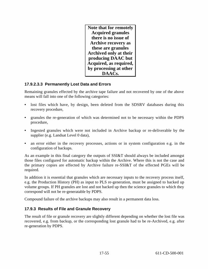
Note that for remotely Acquired granules there is no issue of
Archive recovery as these are granules
Archived only at their producing DAAC but Acquired, as required, by processing at other
DAACs.
17.9.2.3.3 Permanently Lost Data and Errors
Remaining granules effected by the archive tape failure and not recovered by one of the above means will fall into one of the following categories:
• lost files which have, by design, been deleted from the SDSRV databases during this recovery procedure,
• granules the re-generation of which was determined not to be necessary within the PDPS procedure,
• Ingested granules which were not included in Archive backup or re-deliverable by the supplier (e.g. Landsat Level 0 data),
• an error either in the recovery processes, actions or in system configuration e.g. in the configuration of backups.
As an example in this final category the outputs of SSI&T should always be included amongst those files configured for automatic backup within the Archive. Where this is not the case and the primary copies are effected by Archive failure re-SSI&T of the effected PGEs will be required.
In addition it is essential that granules which are necessary inputs to the recovery process itself, e.g. the Production History (PH) as input to PLS re-generation, must be assigned to backed up volume groups. If PH granules are lost and not backed up then the science granules to which they correspond will not be re-generatable by PDPS.
Compound failure of the archive backups may also result in a permanent data loss.
17.9.3 Results of File and Granule Recovery
The result of file or granule recovery are slightly different depending on whether the lost file was recovered, e.g. from backup, or the corresponding lost granule had to be re-Archived, e.g. after re-generation by PDPS.
17-55 611-CD-500-001

Files which are recovered within the Archive/STMGT procedures are re-archived under the same name such that the effected granule(s) are restored as per before the failure.
Where file recovery within STMGT control is not possible the resulting Granule recovery, e.g by PDPS re-generation or via-INS re-ingestion, results in the insertion of a new granule. This new granule will have a new UR and a new 'Production Date and Time'. Particularly where granule re-generation is required, i.e. by PDPS, exact re-production of the original granule (data byte-forbyte) is not guaranteed.
17.9.4 Manual Use of Backup Data for Recovery
The following procedures present the steps required for manual use of local or off-site backup data for recovery. These procedures assume the backup data is available on tape.
17.9.4.1 Manual Data Recovery from Local Backup Tapes
The following procedure presents the steps required for manual data recovery from local backup tapes. This procedure assumes the tape is on-line and in the Powderhorn LSM. Volume groups and tapes are transparent to the automated file and storage management system. As long as the AMASS database is aware of the files, the operator moves data using standard UNIX commands. Table 17.9-2 presents the steps required to follow the process. If you are already familiar with the procedure, you may prefer to use the quick-step table. If you are new to the system, or have not performed this task recently, you should use the following detailed procedure:
1. The operator goes to the STMGT GUI and uses the Configure tab.
2. The operator chooses the Archive Server that is associated with the ServerKey portion of the Archive ID. Example: EcDsStArchiveServerDRP1
3. The operator selects View Volume Groups.
4. The operator clicks on the volume group identifiers that are specified for primary and secondary storage in the archive.
5. Once the operator knows the location of the backup file and the location of the primary file, he/she can issue a copy command (or dd) from the Unix command line to copy the file from the backup version of the file to the primary version.
6. If this recovery is one of a set of files to be restored, e.g. because they were lost from a damaged tape, files recovered from backup should be removed from the list of files to be recovered by other means.
17-56 611-CD-500-001

Table 17.9-2. Manual Data Recovery from Local Backup Tapes Step What to Do Action to Take
1 Configure Select from STMGT GUI
2 Archive Server Select from STMGT GUI
3 View Volume Groups Select from STMGT GUI
4 identifiers Select from STMGT GUI
5 Copy file to primary cp path path
17.9.4.2 Manual Data Recovery from Off-Site Backup Tapes
The following presents the steps required for manual data recovery from off-site backup. Initially, GDAAC off-site backup tapes will be stored at Goddard in another building. If in the future, backup data is sent to Langley, this document will be updated to reflect that procedure. Table 17.9-3 presents the steps required to follow the data recovery process. If you are already familiar with the procedure, you may prefer to use this quick-step table. If you are new to the system, or have not performed this task recently, you should use the following detailed procedure:
To determine whether or not the file exists in the tape library:
1. The operator runs the AMASS fileprint command giving as input the filename and pathname into AMASS cache.
fileprint <filepathname>.
2. The output from fileprint will be a structure of information displayed on the terminal. The operator needs to check on the volume id. There may be two ids, in which case the file is split over volumes.
3. The operator issues an AMASS vollist command giving the volume id as input.
vollist <volumenumber>
• If the volume is active and in a juke box (as displayed in the output from the vollist command), then the operator can move the file to the primary and secondary archive locations by following the same process as in the operations concept for restoring the file from the local backup (essentially this is a case where there are two local backups).
• If the volume is inactive and not in a juke box (as displayed in the out put from the vollist command), then the operator will have to request the tape(s) from the off-site storage.
4. After requesting and receiving the required data from off-site backup, mount the tape and bring it on-line.
a) Insert the tape following procedures in section 17.10.1 STK Media Interface.
• The AMASS database will have a record of the data.
17-57 611-CD-500-001

5. Using an appropriate UNIX command, copy the file(s) from the off-site backup tape(s) to the correct archive directory.
6. If this recovery is one of a set of files to be restored, e.g. because they were lost from a damaged tape, files recovered from backup should be removed from the list of files to be recovered by other means
Table 17.9-3. Manual Data Recovery from Off-Site Backup Tapes Step What to Do Action to Take
1 fileprint <filepathname>. press Return
2 Check volume id Review fileprint
3 vollist <volumenumber> press Return
4 Mount tape Procedure 17.9.1
5 Copy file(s) to primary directory cp path path
17.9.5 Manual Data Recovery From Damaged Cartridge
Manual recovery of AMASS generated data from the D3 cartridge will be necessary in the event that a tape volume becomes damaged. In the course of operations it is possible for a tape to become physically damaged or accidentally overwritten. Some indications of a damaged tape are AMASS read/write errors, or AMASS may determine the volume is unreadable and mark it inactive. In that event, a manual recovery of AMASS generated data from the STK Redwood (D3) cartridge must be attempted.
Due to the technical complexity of the D3 tape recovery, it will be performed by STK personnel. A listing of all the files on tape and the associated start block numbers must be generated and provided to the recovery personnel in order to proceed with the recovery. The archive operator needs to invoke a perl5 utility script and respond to the scripted prompts. The utility will generate three ASCII files, that must be provided to the STK recovery personnel along with the damaged tape. The files are: filelist_volnumber, start_block_listing_volnumber, and README_volnumber, where volnumber is the volume number of the requested tape volume.
The script utility, DsStFilesPerVolume, is located in the utilities directory. The script will initially output directory information followed by three files.
Example directory information output:
/data1/data/:BR:Browse.001:1170:1.BINARY /data1/data/:BR:Browse.000:1170:1.BINARY /data1/data/:SC:MOD00:65001:1.CCSDS /data1/data/:SC:MOD00:65002:1.CCSDS /data1/data/:SC:MOD00:20001:1.CCSDS
17-58 611-CD-500-001

/data1/data/:PH:PH.001:2000000076:1.BINARY /data1/data/:PH:PH.000:2000000076:1.BINARY /data1/data/:QA:QA.001:1003:1.ASCII /data1/data/:QA:QA.001:1004:1.ASCII /data1/data/:QA:QA.001:1005:1.ASCII /data1/data/:OR:OR.001:2100:1.ASCII /data1/data/:OR:OR.001:2101:1.ASCII /data1/data/:OR:OR.001:2102:1.ASCII /data1/data/:OR:OR.001:2103:1.ASCII /data1/data/:AN:AN.001:3100:1.ASCII /data1/data/:AN:AN.001:3101:1.ASCII /data1/data/:AN:AN.001:3102:1.ASCII /data1/data/:AN:AN.001:3103:1.ASCII
The three files produced by DsStFilesPerVolume are as follows:
A readme file (README_TAPE_RECOVERY)
A list of all files on the tape (filelist_v#)
A list of file starting blocks on the tape (start_block_listing_v#)
Where ‘#’ stands for the AMASS designated volume number being recovered. The ‘filelist_v#’ file output is in the form of one file name per line e.g.
/dss_stk2/joel/TestStdSeq6_0_10.wrt /dss_stk2/joel/TestStdSeq6_0_10.wrt /dss_stk2/joel/TestStdSeq6_0_10.wrt /dss_stk2/joel/TestStdSeq6_0_10.wrt /dss_stk2/joel/TestStdSeq6_0_10.wrt
If you are new to the system, you should use the following detailed procedure. If you are familiar with the system, you may prefer to use the quick-step table 17.9-4.
1. Login as amass or root and enter the password
2. Verify AMASS is running using the amassstat command.
3. Run vollist and grep for the volume label in order to get the volume id. vollist|grep SG0003
4. Remove the volume from the library using the voloutlet command. voloutlet volumenumber
• AMASS will move volume to the Cartridge Access Port (CAP) and mark it offline.
5. The DAM will inspect the physical cartridge and tape for damage, see section 17.7.4.2 Inspecting a Cartridge. Any creasing, scratches, snapping, or stretching of the tape may warrant keeping the volume offline and sending it STK for replacement.
17-59 611-CD-500-001

6. If the DAM determines that the tape is damaged, it is shipped to STK for recovery along the three files generated by the DsStFilesPerVolume utility script. In order to run the script you must be logged in as amass or root. a) To start the perl utility script, enter: /usr/ecs/mode/CUSTOM/utilities/DsStFilesPerVolume
• You will be prompted to enter the AMASS volume number for which you wish to generate listings.
a) Enter the volume number of the AMASS volume.
• A message will display informing you when the listings are complete.
b) (optional) If the tape is damaged towards the end of the tape, it will be possible to copy files from the tape using the start_block_listing_v(nn) file generated above. The file to be copied must first be renamed using the Unix mv command and the copied to the original filename ( mv a b; cp b a). It is important that the file remain within the volume group. Care must be taken while doing this procedure. Reading from the part of tape which contains the damaged area may cause damage to the drives. Recovering data in this manner will limit the amount of regeneration of data that may need to be performed. The list of files that are recovered should be kept so that further attempts to regenerate them will not be started. A copy of the list of files that need to be recovered should be kept as well so that any files which fail to be retrieved can be checked against the list first before investigation commences.
7. Send the volume to STK along with the files generated by the perl utility.
• STK will copy all uncorrupted data to a new tape and insert filler data blocks to replace the lost data.
• The filler data is inserted using the original block sequence so that the remaining data can be accessed by AMASS.
• After the data has been copied to a new cartridge, it is shipped back to the DAAC archive with the original volume label and a report indicating which data blocks were replaced with filler data.
8. After receiving the recovered tape back from STK, load the tape into the library using the bulkinlet command: bulkinlet volgroupnumber
• AMASS will read the volume label and place the volume in it‘s home slot.
9. Put the volume online using the volloc command volloc -n volumenumber
17-60 611-CD-500-001

10. Make the volume active using the volstat command volstat -a volumenumber
11. Using the report provided by STK, determine which files have had data blocks replaced and delete those files from the database using standard UNIX commands. All such files must be recorded on a list of non-recovered files. rm filepathname
12. If the DAM determines that the amount of dead space created on the tape exceeds the allowed threshold, the files can be copied to another volume within the volume group and the tape can be reformatted. See Recycle a Volume in the AMASS System Administrator’s User Guide. The AMASS guide can be viewed using Adobe Acrobat and is available electronically on servers g0drg01 and g0drg02 in /usr/amass/books.
13. Once the tape has been returned from STK, the list of files that are on the tape (i.e. the file ‘filelist_v#’ described above) must be used as input to the SDSRV procedure for “Retrieval of File Location Metadata”, as specified in section 17.9.6.1, to recover the ArchiveIDs and checksum for each file.
14. These checksums, and other STK output if available, are then used to validate the files on the returned tape. All files which fail these tests must be deleted as described in point 11, above. They must also be added to the list of non-recovered files. • For files with a non-zero checksum returned by SDSRV the checksum of the
recovered file must be validated with the Unix command ‘cksum’ i.e. cksum filepathnam This command returns one line with three parameters per input file. The file checksum is the first column. For all files where the returned checksum does not match the SDSRV generated checksum the file has failed the checksum test and must be deleted.
• For remaining files, for which the SDSRV returns a checksum of zero, the checksum can not be use to verify validity of the file on the returned tape. If STK have supplied information detailing the corrupt blocks on the tape then that may be used with the data in the “start_block_listing_v#” file to determine which of the files have been corrupted and the remaining files recovered. Alternatively all zero checksum files should be assumed to be corrupted and not recovered, i.e. they must be deleted.
15. The list of non-recovered files then serves as input to subsequent file recovery by other means, i.e. as specified in section 17.9.2.2.
17-61 611-CD-500-001

Table 17.9-4. D3 Cartridge Data Recovery - Quick-Step Procedures Step What to Enter or Select Action Taken
1 amass or root press Return
2 amasssstat press Return
3 vollist|grep SG0003 press Return
4 voloutlet volumenumber proceed to step 5
5 Check for Physical tape damage Tape Damage ? Y- run DsStFilesPerVolume script N- Enter cartridge into archive
6 ship to STK with files
7 bulkinlet volgroupnumber press Return
8 volloc -n volumenumber press Return
9 volstat -a volumenumber press Return
10 rm filepathname proceed to step 5
11 Run SDSRV procedure
12 Send retrieve request to SDSRV
17.9.6 SDSRV Procedures in Support of Data Recovery
This section details steps in the recovery of lost archive data which must be executed against the SDSRV database. It contains two procedures. The first returns file metadata including file checksums to the Archive/STMGT operator for use with file recovery from tapes. The second generates granule metadata for use by the Planning sub-system, PLS, in re-creating granules from which files have been irrecoverably lost.
The “lists” which form the interfaces between these procedures should be exchanged as electronic files e.g. as email ‘attachments’ or by copying.
These operations procedures are valid for ECS Release B drop 4PL7 and subsequent 4Pn drops. They should be used in conjunction with the related Archive/STMGT procedures (17.9.5) and overview procedure (17.9.2.1, 17.9.2.2).
17.9.6.1 SDSRV Retrieval of File Location Metadata
For information on the context of this procedures and its interfaces see section 17.9.1. The usual entry point to this process is the Archive/STMGT procedure for “Manual Data Recovery from Damaged Cartridge” (section 17.9.5). It returns its output to its calling procedure.
The input to this procedure is a list of the unique file names of files in the Archive effected by a tape failure e.g. as generated within procedure 17.9.5 by the script DsStFilesPerVolume. The list is called the “Effected File List” and is referred to below as the EFL. The example file name used for it is “eflfile.txt”. The file names in the EFL will match the DsMdFileStorage.internalFileName column within the SDSRV metadata database.
17-62 611-CD-500-001

The output from this procedure is a list of file metadata (archiveIDs and checksum) for each file named in the input. It is called the “Effected File Metadata” list and is referred to below as the EFM. The example file name used for it is “eflmetadata.txt”. It is used to determine the backup locations, if any, of lost files and to verify the checksum of files restored via tape drive vendor (StorageTek) support.
This procedure has the following dependencies:
• The operator is working on a machine from which SQL connections can be made to the SDSRV SQL server, e.g. ‘t1acg0’ and that server recognizes the sybase account EcDsScienceDataServer.
• The Unix account in use has execute permission on the required scripts, the ‘path’ shell variable set to include a directory where the command ‘isql’ is located and the SYBASE (Sybase ‘home’) environment variable set appropriately (e.g. setenv SYBASE /tools/sybOCv11.1.0).
• The operator knows the password for the SDSRV Sybase user EcDsScienceDataServer
Procedure:
1. Receive the Effected File List (EFL) generated by the procedure e.g. as generated by the utility DsStFilesPerVolume (see section 17.9.5) as an electronic file. Save a local copy of the file with the name ‘eflfile.txt’ or similar.
2. Execute the shell script DsDbSrFileLocMetadata at the Unix prompt against this file as follows: DsDbSrFileLocMetadata eflfile.txt eflmetadata.txt
3. At the prompt enter the Sybase password for the Sybase account EcDsScienceDataServer.
For each of the —internalFileNames“ in the input —Effected File List“ the script retrieves from the SDSRV database the file primary archive ID and checksum and the backup and offsite archive IDs if they are set.
4. Check that the output file is not empty (i.e. of zero length) using the ”ls‘ command. If the file is of zero length either the input file was of zero length or an unexplained error occurred.
ls -l eflmetadata.txt
5. Visually inspect the file to verify success of the command (using e.g. ”more‘). The output file will be in two sections. First the Effected File metadata found within SDSRV Inventory database. Lines in this section appear as follows:
17-63 611-CD-500-001

InternalFileName_found_in_SDSRV_Inventory_Metadata_Database Tue Jan 5 18:26:07 EST 1999
:BR:Browse.001:1170:1.BINARYDRP1_TS3:VG1 NOT_SUPPLIED NOT_SUPPLIED "NONE" 0 1000 BRBrowse.0011170
:SC:MOD00:65001:1.CCSDSDRP1_TS3:VG1 NOT_SUPPLIED NOT_SUPPLIED"Oct 10 1996 12:02:00:000AM" 0 1000 SCAST_04.00120001
:PH:PH.001:2000000076:1.BINARYDRP1_TS3:VG1 NOT_SUPPLIED NOT_SUPPLIED "NONE" 0 65536 PHPH.0012000000076
:QA:QA.001:1003:1.ASCIISGI_RCCLAB1DEV:VG1 NULL NotSupported "NONE" 0 0 QAQA.0011003
:OR:OR.001:2100:1.ASCIIRECOV_TEST:VG1 NOT_SUPPLIED NOT_SUPPLIED "NONE" 0 0 OROR.0012100
:AN:AN.001:3100:1.ASCIIRECOV_TEST:VG1 NOT_SUPPLIED NOT_SUPPLIED "NONE" 0 0 ANAN.0013100
Second files not found within SDSRV. This section will usually be empty.
6. It is advisable to check for errors in the output of the script using the Unix ”grep‘ command. This is done by searching the output for occurrences of the strings ”msg‘ and ”error‘. To do this execute the following at the Unix prompt:
grep œi msg eflmetadata.tx | wc -l
grep œi error eflmetadata.tx | wc -l
If no errors occurred these commands will both output ‘0’ (zero). Any other output means there were errors in the process. If errors are found they must be diagnosed based on the error message(s) and the procedure repeated after correction of the input file.
7. When the output file passes the above tests it should be passed back to the calling procedure.
17.9.6.2 SDSRV Retrieval of Granule Production History Metadata
For information on the context of this procedures and its interfaces see section 17.9.1. The entry point to this process is the Archive/STMGT procedure for “Data Recovery Procedure for Known Files” (section 17.9.2.2). Its input is a list of files remaining to be recovered, referred to below as the “Lost File List” (LFL). Its output serves as input to the PDPS/PLS procedure for granule regeneration, “Re-Generate Granules Effected by Loss of Files from the Archive”, in Section 13.1.6.
17-64 611-CD-500-001
Note this procedure assumes that:
• the Algorithm Package information has been inserted into the SDSRV for all associate datatypes. This is populated by SSI&T processing. There may be a period of time in the “granules” lifetime when this information is not populated. Attributes PGEName and PGEVersion are affected
The goal of this procedure is to list PLS required granule metadata for those granules which the local PDPS should be able to re-generate. This decision is based on finding valid Production History URs for the ‘lost’ granules in the local SDSRV database.
Output from this procedure is a file containing:
• “Granules for PDPS Re-generation” - those found within SDSRV. These are passed to the PLS operators for re-generation using the procedure “Re-Generate Granules Effected by Loss of Files from the Archive” (section 13.1.6).
• “Residual Granules to Recover” - those not found within SDSRV inventory. This is passed back to the top-level procedure. This may include granules that have been removed by the “Physical Delete” service within SDSRV.
Procedure:
1. Receive the “Lost File List” (LFL) e.g. as generated by the procedure in section 17.9.5, as an electronic file. Save a local copy of the file with the name ‘lflfile.txt’ or similar.
Execute the shell script DsDbSrFileLocMetadata at the Unix prompt against this file as follows:
DsDbSrGranPHMetadata lflfile.txt lgrmetadata.txt
2. At the prompt enter the Sybase password for the Sybase account EcDsScienceDataServer.
The output file will be divided into two sections:
• Granule metadata found within SDSRV Inventory database for use with e.g. PDPS granule re-generation.
• Residual files to recover. Those files not found within SDSRV.
For each of the —internalFileNames“ in the input —Lost File List“ for which related Granule metadata is found in this SDSRV the script retrieves the following pertaining to the Granule of which that file was part:
- the —GeoID“ (partial UR),
- the UR of its associated Production History granule, if available,
17-65 611-CD-500-001

- the ESDT shortname and versionID,
- the granule beginning date and time and ending date and time.
1 . Verify that the metadata extraction was successful by applying to the output file (lgrmetadata.txt) the tests as specified in steps 4, 5 and 6 of section 17.9.4.1, above. Lines in this section appear as follows:
Granule_metadata_found_within_SDSRV_Inventory_database Tue Jan 5 18:26:53 EST 1999
:BR:Browse.001:1170:1.BINARY0 1000 BRBrowse.0011170 PGEName 1 "None" "None" "NONE" "NORMAL"PH_Does_Not_Apply
:SC:MOD00:65001:1.CCSDS0 1000 SCAST_04.00120001 PGEName 1"Jan 1 1997 12:00:00:000AM" "Jan 1 1997 12:00:00:000AM" "Oct 10 1996 12:02:00:000AM" "NORMAL" 2NO_PH
:PH:PH.001:2000000076:1.BINARY0 65536 PHPH.0012000000076 PGEName 1 "None" "None" "None" "NORMAL" PH_Does_Not_Apply
:QA:QA.001:1003:1.ASCII 0 0 QAQA.0011003 PGEName 1 PH_Does_Not_Apply
:OR:OR.001:2102:1.ASCII 0 0 OROR.0012102 PGEName 1 PH_Does_Not_Apply
:AN:AN.001:3100:1.ASCII 0 0 ANAN.0013100 PGEName 1 PH_Does_Not_Apply
"None" "None" "None" "NORMAL"
"None" "None" "None" "NORMAL"
"None" "None" "None" "NORMAL"
Granule_metadata_not_found_within_SDSRV_Inventory_database Tue Jan 5 18:26:53 EST 1999
2. When the output file passes the above tests it should be passed back to the calling procedure.
Note:
• For the at-launch system (Drop 4P*), granule metadata for recovered files will produce “logical duplicate” metadata, one set for the original “lost” files and another for the “regenerated” files.
• Granules for recovered files will by definition have a different granuleUR (dbID).
17-66 611-CD-500-001

1
2
3
4
5
6
7
8
17.10 Operations of Archive Media Interfaces
Operations of archive media interfaces involves the insertion and removal of archive media cartridges, tapes, or optical disk. Archive media insertion and removal from the library is an automated or manual function. The method used is dependent upon the amount of media involved. Large amounts of media is loaded or unloaded manually. Small amounts are handled automatically. Archive media is added or removed via the Cartridge Access Port (CAP) on the STK, the EMASS Entry Interface Facility (EIF), or the EMASS I/O Unit depending on the model used.
The term manual loading can have one of two meanings. The first is the loading of cartridges directly into the archive storage slots. The second is the loading of media into the CAP, EIF or I/O Unit and commanding the robotic units through the EIF keypad or operator terminal to insert the tapes into the archive.
The STK CAP and EMASS EIF or I/O Units also have fully automatic operational function. These functions allow an operator to set an operational mode that inserts media into the archive after loading and closing of the CAP, EIF, or I/O. In this mode, the system inserts without operator intervention.
The Activity Checklist depicted in Table 17.10-1 provides an overview of the operations of the archive media interfaces. Column one (Order) shows the order in which tasks should be accomplished. Column two (Role) lists the Role/Manager/Operator responsible for performing the task. Column three (Task) provides a brief explanation of the task. Column four (Section) provides the Procedure (P) section number or Instruction (I) section number where details for performing the task can be found.
Table 17.10-1. Operations of Archive Media Interfaces - Activity Checklist (1 of 2)
Order Role Task Section
DIT STK Media Interface (I) 17.10.1
DIT Manual Insertion of STK Media (I) 17.10.1.1
DIT Insertion of STK Media Using Bulkload (P) 17.10.1.1.1
DIT Insertion of STK Media Using Bulkinlet (P) 17.10.1.1.2
DIT Automatic Insertion of STK Media (P) 17.10.1.2
DIT Manual Ejection of STK Media (I) 17.10.1.3
DIT Commanding Ejection of STK Media (P) 17.10.1.3.1
DIT Manually Removing STK Media from the Powderhorn Library Storage Module (LSM)
(P) 17.10.1.3.2
9 DIT EMASS Media Interface Units (I) 17.10.2
10 DIT Inserting Media into the EMASS EIF (P) 17.10.2.1
11 DIT Automatically Loading EMASS Archive Media (P) 17.10.2.2
12 DIT Manually Loading EMASS Archive Media (P) 17.10.2.3
13 DIT Ejecting EMASS Archive Media Using AMASS (P) 17.10.2.4
17-67 611-CD-500-001

Table 17.10-1. Operations of Archive Media Interfaces - Activity Checklist (1 of 2)
Order Role Task Section
14 DIT Ejecting EMASS Archive Media Using DAS (P) 17.10.2.5
15 DIT Removing Media from the EMASS EIF (P) 17.10.2.6
16 DIT Manual Ejection of EMASS Media (P) 17.10.2.7
17 DIT Removing Problem Media from the EMASS EIF (P) 17.10.2.8
18 DIT EMASS I/O Unit (I) 17.10.3
19 DIT Inserting Media into the EMASS I/O Unit (P) 17.10.3.1
20 DIT Ejecting Media from the EMASS I/O Unit (P) 17.10.3.2
21 DIT Removing Problem Media from the EMASS I/O Unit (P) 17.10.3.3
17.10.1 STK Media Interface
The STK employs a CAP as an interface unit. The CAP is the access door to the storage unit as well as the means of inserting and ejecting media for the archive user. The CAP mode controls how a CAP will be used for cartridge enters and ejects. CAP modes are manual and automatic. In manual mode the CAP is locked when not in use. This is the initial mode for all multi-cartridge CAPs. When in manual mode, you can enter or eject cartridges only after issuing a command. In automatic mode, the CAP is unlocked when not in use. While in automatic mode, you can enter or eject cartridges without explicitly issuing an enter command. The enter is initiated when you open the CAP door, place a cartridge inside and close the CAP. Whether the CAP mode is in manual or automatic, you must explicitly issue an eject command to eject a cartridge.
17.10.1.1 Manual Insertion of STK Media
The robotic unit retrieves cartridges from the CAP in two modes, manual and automatic. Manual mode requires the operator to request robot intervention in inserting media by issuing a command. This section discusses the manual insertion of media into the STK silo. The following procedures details how to insert tape cartridges by entering the silo, and by loading the CAP. Note that the ejection of media is always an operational request.
Note: If using an ACSLS or DAS command to insert media, be aware that AMASS will not know of it’s existence.
17.10.1.1.1 Insertion of STK Media Using Bulkload
Since the CAP functions as an access door, manual loading of media into storage slots is possible. When inserting a large number of tapes, it is faster to enter them directly into the silo by entering through the CAP. This is normally only done when populating a new silo.
Table 17.10-2 presents the steps required for manual insertion of media using the CAP. If you are already familiar with the procedures, you may prefer to use this quick-step table. If you are new to the system, or have not performed this task recently, you should use the following detailed procedure:
17-68 611-CD-500-001

1
2
3
4
5
6
7
1. Open an ACSSA window on the SUN Workstation: Login as acssa and enter password
• ACSSA mode entered and cmd_proc window opened.
2. Enter vary lsm 0,0, offline
• There will be an audible click and the door will unlock
3. Unlock CAP door with key
• Safety light red, caution
4. Set latch for safety light to become green. Lock the latch and remove the key
• Prevents personnel from being locked inside.
5. Enter the LSM and load or eject cartridges manually
6. Close CAP door
7. Lock door with key, lock latch, wait for robotic diagnostic completion
8. From an ACSSA cmd_proc window, enter audit
9. ACSLS will scan every volume label and update the ACSLS database.
10. Enter bulkload -s
• AMASS will synchronize it‘s database with ACSLS
Table 17.10-2. Manual Insertion using CAP as an Access Door Step What to Enter or Select Action to Take
enter ACSSA window on SUN Workstation
vary lsm 0,0 offline audible click, door unlocks
unlock CAP door with key safety light red, caution
set latch for safety light to become green OK to enter
load or eject cartridges manually
close CAP door
lock door with key, lock latch, wait for robotic diagnostic completion
8 audit audit performed
9 bulkload –s database sync
17-69 611-CD-500-001

17.10.1.1.2 Insertion of STK Media Using Bulkinlet
Manual insertion of STK media through the CAP requires the operator to place tape cartridges into the CAP. The CAP has a capacity of 21 cartridges, three rows of seven each as shown in Figure 17.10-1. Insertion of cartridges must begin at the left hand corner of the top rack. If this is not done, the system will not insert the media. No spacing is allowed between media slots. The system interprets the space as the end of media for insertion. It stops input operations until door is opened and cartridges are input again.
The bulkinlet command is used to load multiple volumes through the mailbox, create entries in the AMASS database for new volumes, and mark volumes Online in the AMASS database. For tracking purposes, AMASS assigns each new volume a unique volume number. If you attempt to load several volumes at one time and one volume fails to load, AMASS will not load the remaining volumes after the first failure. For example, if you load volumes 1 through 6 and volume 3 is unsuccessful, AMASS successfully loads volumes 1 and 2 but does not load volumes 3, 4, 5, and 6.
1 2 3 4 7
8 9 10 11 12 13 14
15 16 17 18 19 20 21
6 5
Figure 17.10-1. Cartridge Insertion Order into CAP
Table 17.10-3 presents the steps required for manual insertion of media using the CAP. If you are already familiar with the procedures, you may prefer to use this quick-step table. If you are new to the system, or have not performed this task recently, you should use the following detailed procedure:
1. Login as amass or root and enter the password
2. Load volumes into the CAP mailbox. Make sure to start in the upper left slot and fill slots to the right and close the CAP.
17-70 611-CD-500-001

3. Enter the following AMASS command: bulkinlet volgroup
• volgroup is the number of the volume group where the volumes are to be assigned. Options are: 0-2047, SP, and CL
• audible click indicating the CAP is unlocked
• AMASS assigns a unique volume number to each volume.
a) All new volumes in the AMASS database have an initial status of unformatted (U) and inactive (I). If the inserted volumes are new (unknown to AMASS), prepare the volumes so AMASS can read or write to them using the format procedure in section 17.5.1.
Table 17.10-3. Manual Insertion Using bulkinlet Step What to Enter or Select Action to Take
1 Login as amass or root
2 Load volumes into the CAP mailbox
3 Enter bulkinlet volgroup audible click, door unlocks
4 For new volumes set tapelength, format and activate see section 17.5.1
see AMASS System Administrator’s Guide
17.10.1.2 Automatic Insertion of STK Media
Automatic insertion of STK media into the CAP is accomplished without operator intervention.
Table 17.10-4 presents the steps required for automatic insertion of STK media using the CAP. If you are already familiar with the procedures, you may prefer to use this quick-step table. If you are new to the system, or have not performed this task recently, you should use the following detailed procedure:
1. Enter ACSSA window on SUN Workstation: Login as acssa and enter password • ACSSA mode entered and cmd_proc window opened.
2. If already in automatic mode go to step 3. If not, enter: set cap 0,0,0 mode automatic
• audible click indicating door is unlocked
3. Open CAP media door
4. Load cartridges into the door , top left slot first
17-71 611-CD-500-001

5. Close CAP door
• Robot inserts media without operator intervention.
6. If entering new media (unknown to AMASS) update the amass database using the command:volnew volgroup slot vollabel
ex. volnew SP NET SG0009
Table 17.10-4. Automatic Insertion of STK Media Step What to Enter or Select Action to Take
1 enter ASCCA window on SUN Workstation
2 enter set cap 0,0,0 mode automatic audible sound from CAP, CAP unlocked
3 open CAP media door
4 load cartridges into the door top left slot first
5 close CAP door robot inserts media without operator intervention
6 volnew volgroup slot vollabel
17.10.1.3 Manual Ejection of STK Media
As mentioned previously, ejection of STK media is always requires manual intervention. Manual ejection can be by means of issuing commands or physically entering the Powderhorn LSM and removing a tape. Keep in mind that when a tape is physically removed from archive, the AMASS and ACSLS databases will think the tape is still in the LSM.
17.10.1.3.1 Commanding Ejection of STK Media
Table 17.10-5 presents the steps required for comanding ejection of STK media using the CAP. If you are already familiar with the procedures, you may prefer to use this quick-step table. If you are new to the system, or have not performed this task recently, you should use the following detailed procedure:
1 . Determine which volumes you want to remove, utilizing the volume number. If necessary to review volume numbers and other information, log into the AMASS host, type vollist and then press the Enter key.
2. If there are only a few volumes to remove, then for each volume to be removed type: /usr/amass/bin/voloutlet #, where # is the volume number, and then press the Enter key.
• AMASS marks the volume off-line and the volume is transferred to the CAP.
17-72 611-CD-500-001

3. For the STK Powderhorn, open the recessed latch on the Cartridge Access Port (CAP) door and remove the tape(s)
Table 17.10-5. Commanding Ejection of STK Media Step What to Do Action to Take
1 Vollist Press return
2 voloutlet volnumber Press return
3 Open CAP and remove tape
17.10.1.3.2 Manually Removing STK Media From the Powderhorn Library Storage Module (LSM)
Table 17.10-6 presents the steps required for manual removal of media from the STK Powderhorn using the CAP as an access door. If you are already familiar with the procedures, you may prefer to use this quick-step table. If you are new to the system, or have not performed this task recently, you should use the following detailed procedure:
1. Enter ACSSA window on SUN Workstation: Login as acssa and enter password
• ACSSA mode entered and cmd_proc window opened.
2. Enter vary lsm 0,0 offline
• audible click indicating door is unlocked
2. Unlock CAP door with key and open the access door.
• Safety light red, caution
2. Set latch for safety light to become green by locking the CAP.
3. Enter the Powderhorn LSM and load or remove cartridges manually
4. Close CAP door
5. Lock door with key, wait for robotic diagnostic completion
17-73 611-CD-500-001

1
2
3
4
5
6
7
Table 17.10-6. Manually Removing STK Media From the LSM Step What to Enter or Select Action to Take
enter ASCCA window on SUN Workstation
vary lsm 0,0 offline Listen for audible click
unlock CAP door with key safety light red, caution
set latch for safety light to become green OK to enter
load or remove cartridges manually
close CAP door
lock door with key wait for robotic diagnostic completion
17.10.2 EMASS Media Interface Units
There are two EMASS media interface units for data archiving being utilized. Different media I/O interfaces exist for these units. The instructions in this section describe the manual procedures for operating either the Entry Interface Facility (EIF) or I/O Unit. The procedures include the insertion and removal of media before automated loading or after automated ejection from the archive.
The GODDARD DAAC EMASS AML/2 incorporates an EIF. Smaller capacity EMASS models may incorporate an I/O Unit.
17.10.2.1 Inserting Media into the EMASS EIF
The Goddard DAAC EMASS unit utilizes an Entry Interface Facility (EIF). The EIF is a media handling I/O unit. It utilizes three sections. Two of these sections allow the operator to input and output media. This is for archive storage as well as Foreign media. Foreign media have no bar-code number for storage to the archive. The media travels directly from the Foreign box to a selected drive for operations. When completed, it returns to the Foreign box for removal from the system.
A third section allows for the ejection of media classified as Problem media from the archive storage. The Problem box is a separate entity populated by the archive system. Removal of Problem media is an operator function.
Media are inserted into and ejected from the EMASS archive system through the EIF. Cartridges are loaded by hand into hand-carry racks, each with a capacity of 30 half-inch tape cartridges or 22 optical cartridges. The robot system physically moves each cartridge from the EIF to the AML. EMASS recommends that you turn ON the Auto Import option for each library. With this option on, you only need to place media into the EIF and close it.
The EIF uses a keypad with a display for commands. Figure 17.10-2 depicts the configuration for the EIF keypad configuration. The EIF handling boxes for Insert/Eject/Foreign Media compartments are fully selectable for either operation.
17-74 611-CD-500-001
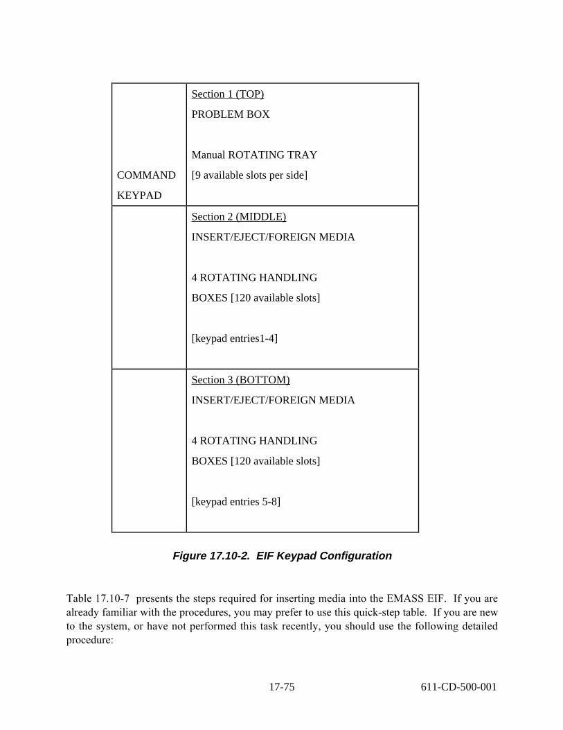
COMMAND
KEYPAD
Section 1 (TOP)
PROBLEM BOX
Manual ROTATING TRAY
[9 available slots per side]
Section 2 (MIDDLE)
INSERT/EJECT/FOREIGN MEDIA
4 ROTATING HANDLING
BOXES [120 available slots]
[keypad entries1-4]
Section 3 (BOTTOM)
INSERT/EJECT/FOREIGN MEDIA
4 ROTATING HANDLING
BOXES [120 available slots]
[keypad entries 5-8]
Figure 17.10-2. EIF Keypad Configuration
Table 17.10-7 presents the steps required for inserting media into the EMASS EIF. If you are already familiar with the procedures, you may prefer to use this quick-step table. If you are new to the system, or have not performed this task recently, you should use the following detailed procedure:
17-75 611-CD-500-001

1. Verify that the Main Menu on the EIF keypad is active
• Display is lit
2. Select Insert with cursor keys
• Insert is highlighted
a) Press Enter
• Display shows selection for, handling box number entry
3. Select handling box (1-8)
• Selection is displayed
a) Press Enter
• Handling box selected is rotated, into access position
4. Select Open Door with cursor keys
• Display prompts for reply to open door for access
a) Press Enter
• Door opens
5. Put media in Insert I/O box selected
• Option 1 Take out handling box and load with media
• Option 2 Load handling box while in place
• Make sure box is seated correctly
6. Select Close Door with cursor keys
• Display prompts for reply to close door
a) Press Enter
• Door closes, tray rotates 180 degrees
17-76 611-CD-500-001

Table 17.10-7. Inserting All Media Types into EIF - Quick-Step Procedure Step Action to Take Verification
1 Verify Main Menu is active on the EIF Display is lit
2 Select Insert with cursor keys Insert is highlighted
3 Press Enter Display shows selection for, handling box number entry
4 Select handling box (1-8) Selection is displayed
5 Press Enter Handling box selected is rotated, to into access position
6 Select Open Door with cursor keys Display prompts for reply to, open door for access
7 Press Enter Door opens
8 Put media in Insert I/O box selected Options: 1) Take out handling box and load with media 2) Load handling box while in place Make sure box is seated correctly
9 Select Close Door with cursor keys Display prompts for reply to close door
10 Press Enter Door closes, tray rotates 180 degrees
17.10.2.2 Automatically Loading EMASS Archive Media
Table 17.10-8 presents the steps required for inserting media into the EMASS EIF. If you are already familiar with the procedures, you may prefer to use this quick-step table. If you are new to the system, or have not performed this task recently, you should use the following detailed procedure:
1. To log in, type amass or root and then press the Enter key.
• A password prompt is displayed.
2. Enter the Password, then press the Enter key.
• Remember that Password is case sensitive.
• You are authenticated (as amass or root) and returned to the UNIX prompt.
3.� Remove the left box to insert or remove tape media, and/or remove the right box to insert or remove optical media.
4. � Write down or note the bar code numbers on the labels of the cartridges, insert the cartridges in the removed box(es), reinsert the box(es) in the EIF, and close the door.
17-77 611-CD-500-001

• The robot scans all the volumes.
5. At the AMASS host, type /usr/amass/bin/bulkinlet SP and then press the Enter key.
• Data for the newly inserted media are displayed, including bar codes, associated volume numbers, and, in the flag column, the letters IUO, indicating that the volumes are inactive (I), unformatted (U), and offline (O).
6.� For any newly inserted media, it is necessary to issue a formatting command. For tapes, type volformat # , where # is the volume number. For optical cartridges, type volformat -p #, where # is the volume number. You can enter more than one, separating each number from the preceding one with a space.
Note: You may wish to use the & (to run the process in the background) for formatting tapes as well as for optical cartridges. It is highly recommended for formatting optical cartridges, because of the length of time required.
7. A message requests confirmation that you wish to continue.
8. Type y and then press the Enter key.
• A message is displayed requesting further confirmation, stating that The following volumes will be formatted: and listing volume numbers, followed by (Y-N).
9. Type y and then press the Enter key.
• After a few minutes (or, for optical cartridges, about an hour for each), a message; Completed formatting all volumes is displayed.
10.� To verify that the volume(s) are inserted, type /usr/amass/bin/vollist and then press the Enter key.
11. � Data for the media are displayed; the flag column shows that the newly formatted volumes are inactive (I).
12.� To activate the media for use, type:
volstat -a
13.� Data for the media are displayed; the flag column shows that the volumes are now active (A).
17-78 611-CD-500-001

Table 17.10-8. Automatically Loading EMASS Archive Media -Quick-Step Procedure
Step What to do Action to Take
1 amass or root Press return
2 Insert or remove media Remove left tape box for tape media or right box for optical media
3 Load cartridges Note lables, load boxes and insert into EIF
4 /usr/amass/bin/bulkinlet SP Press return
5 volformat (-p) volnumber Press return
6 Confirm format Enter Y
7 /usr/amass/bin/vollist Press return
8 volstat –a Press return
17.10.2.3 Manually Loading EMASS Archive Media
With the bulkload command, you bypass the EIF and manually load media directly into the library bins. Typically, this will only be done at the initial load of the system with large numbers of media volumes. The bulkload command enables AMASS to determine what type of media have been placed in the library and to convey this information to the AMASS database. The following procedures are applicable. Table 17.10-9 presents the steps required for inserting media into the EMASS bins. If you are already familiar with the procedures, you may prefer to use this quick-step table. If you are new to the system, or have not performed this task recently, you should use the following detailed procedure:
Warning
If it is necessary to enter the AML after AMASS is started, the following step (Step 1) must be performed first to avoid hazard and ensure safety of personnel and equipment.
1.� Turn the Operation Mode switch, located above the AMU keyboard shelf, to manual by rotating it to the horizontal position.
• The Control Off amber light comes on.
• All power to the robot and tower is then turned off and it is safe to enter the enclosed area.
17-79 611-CD-500-001

2. Press the Illumination On button.
• The overhead light in the AML comes on.
3. Turn the key to the access door two full turns clockwise to open the door.
• Physically enter the library and load the desired media into the bins.
Caution
The following step (Step 4) must be performed before leaving the enclosed area to ensure proper functioning of the AML robot.
4.� Before leaving the enclosed area, straighten the robot arm so that it is parallel to the main hallway and pointing to the front of the AML.
Warning
To avoid hazard and ensure safety of personnel and equipment, the following step (Step 5) must be performed before Step 6.
5. On leaving the area, lock the door by turning the key two full turns counterclockwise.
6.� Turn the Operation Mode switch, located above the AMU keyboard shelf, to automatic by rotating it to the vertical position.
• The Control Off amber light goes off.
7.� From a DAS command line, execute the inventory command, DAS will scan all AML media and update the archive catalogue.
• The archive catalogue can be viewed with the list command.
8. At the AMASS host, type bulkload -s SP and then press the Enter key.
• The AMASS database is populated with data for the volumes in the AML.
9 . � To view a list of media in the AML, type medialist [-#] (where # is the jukebox identification number), and then press the Enter key.
• If you do not specify a jukebox number with the -# option, the default is 1, which specifies the EMASS AML optical disks.
17-80 611-CD-500-001

• If you want to specify a different jukebox, specify -2 to indicate the EMASS AML tapes.
• The utility reads the library element status stored in the library, and information about the library contents, including the status (FULL or EMPTY) of the elements.
Table 17.10-9. Manually Loading EMASS Archive Media - Quick-Step Procedure Step Action to Take Verification
1 Turn operational mode switch to manual Control Off amber light comes on
2 Press the Illumination On button. The overhead light in the AML comes on
3 Turn key two full turns clockwise Enter library and load media
4 Turn the Operation Mode switch to Automatic
The Control Off amber light goes off
5 Inventory DAS scans media
6 bulkload -s SP AMASS database is updated
17.10.2.4 Ejecting EMASS Archive Media Using AMASS
Ejecting media from archive is always a manual operation. Problem media however, may be moved to the Problem Box automatically. Table 17.10-10 presents the steps required for ejecting EMASS archive media using AMASS commands. If you are already familiar with the procedures, you may prefer to use this quick-step table. If you are new to the system, or have not performed this task recently, you should use the following detailed procedure:
1. Determine which volumes you want to remove by utilizing the volume number. If necessary to review volume numbers and other information, log into the AMASS host, type /usr/amass/bin/vollist and then press the Enter key.
2. If there are only a few volumes to removed; for each volume to be removed type: /usr/amass/bin/voloutlet #, where # is the volume number, and then press the Enter key.
• AMASS marks the volume off-line and the volume is transferred to the EIF.
3. Remove the left box to remove tape media, and/or remove the right box to remove optical media.
17-81 611-CD-500-001

Table 17.10-10. Ejecting EMASS Archive Media Using AMASS -Quick-Step Procedure
Step What to do Action to Take
1 /usr/amass/bin/vollist Press return
2 /usr/amass/bin/voloutlet # Press return
3 Remove media Remove the left box to remove tape media, and/or remove the right box to remove optical media
17.10.2.5 Ejecting EMASS Archive Media Using DAS
Ejecting media from archive is always a manual operation. Problem media however, may be moved to the Problem Box automatically. Table 17.10-11 presents the steps required for ejecting EMASS archive media using DAS commands. If you are already familiar with the procedures, you may prefer to use this quick-step table. If you are new to the system, or have not performed this task recently, you should use the following detailed procedure:
1. Determine which volumes you want to remove by utilizing the volser label. If necessary to review volser labels, log into the DAS host, type dasadmin list and then press the Enter key. For more information on the use of DAS commands, see the DAS Administration Guide . The DAS guide can be viewed using Adobe Acrobat and is available electronically on servers g0drg01 and g0drg02 in /usr/amass/books.
2. After determining which volumes to remove, type:
dasadmin eject (ej) [-c] [-t media-type] volser-rangearea
• DAS marks the volume ejected and the volume is transferred to the EIF.
• See Table 17.10-12 for parameter descriptions.
3. Remove the left box to remove tape media, and/or remove the right box to remove optical media.
Table 17.10-11. Ejecting EMASS Archive Media Using DAS -Quick-Step Procedure
Step What to do Action to Take
1 dasadmin list Press return
2 dasadmin eject (ej) [-c] [-t media-type] volser-rangearea
Press return
3 Remove media Remove the left box to remove tape media, and/or remove the right box to remove optical media
17-82 611-CD-500-001

Table 17.10-12 provides an explanation of DAS command parameters. Table 17.10-13 provides a list of media types specified by the parameter media-type.
Table 17.10-12. Parameter Explanation -c The optional parameter -c indicates to DAS a complete eject
operation requested (volser will be removed from the archive catalog)
media-type The optional media-type parameter allows the specification of a media type (see table 9-13).
volser-range The volser-range specifies one or more volsers to be ejected. The volser range must be in one of the following formats: volser | volser, volser,... | volser-volser.
area The area specifies the eject area name in the I/O unit to which the volume(s) are moved (e.g. E01).
Table 17.10-13. Media Types Media Types Type Explanation AMU-
Types
3480 3480 and 3490 and 3490E
Cartridges C0
3590 3590/8590 Cartridges C2
OD-THIN Optical disk Reflection (9 mm) O0
OD-THICK Optical disk 512, MO/WORM (11mm) O1
CD CD-ROM disk (CD-Caddy) C6
TRAVAN TRAVAN cartridge V5
BETACAM BETACAM cartridge V8
DECDLT TK-85 Digital Linear Tape (DLT) C1
8MM D8 cartridge (8 mm) V1
4MM DDS or DAT cartridge (4mm) (Digital Data Storage) V2
VHS VHS cartridge V0
D2 Small and medium cartridge V3 (V4)
DTF DTF small and medium cartridge V6 (V7)
17.10.2.6 Removing Media from the EMASS EIF
Table 17.10-14 presents the steps required for removing all ejected media types from the EIF. If you are already familiar with the procedures, you may prefer to use this quick-step table. If
17-83 611-CD-500-001
you are new to the system, or have not performed this task recently, you should use the following detailed procedure:
1. Verify that the Main Menu on the EIF keypad is active
• Display is lit
2. Select Eject with cursor keys
• Eject is highlighted
3. Press Enter
• Display shows selection for, handling box number entry
4. Select Eject handling box (1-8)
• Selection is displayed
5. Press Enter
• Handling box selected is rotated, into access position
6. Select Open Door with cursor keys
• Display prompts for reply to open door for access
7. Press Enter
• Door opens
8. Remove media in Eject I/O box.
• Option 1 Take out handling box and unload media
• Option 2 Unload handling box while in place
• Make sure box is seated correctly
9. Select Close Door with cursor keys
• Display prompts for reply to close door
10. Press Enter
• Door closes
17-84 611-CD-500-001

Table 17.10-14. Removing All Ejected Media Types from EIF -Quick-Step Procedure
Step Action to Take Verification
1 Verify Main Menu is active on the EIF Display is lit
2 Select Eject with cursor keys Eject is highlighted
3 Press Enter Display shows selection for, handling box number entry
4 Select Eject handling box (1-8) Selection is displayed
5 Press Enter Handling box selected is rotated, to into access position
6 Select Open Door with cursor keys Display prompts for reply to, open door for access
7 Press Enter Door opens
8 Remove media in Eject I/O box selected Options: 1) Take out handling box and unload media 2) Unload handling box while in place Make sure box is seated correctly
9 Select Close Door with cursor keys Display prompts for reply to close door
10 Press Enter Door closes
17.10.2.7 Manual Ejection of EMASS Media
As mentioned previously, ejection of STK media is always requires manual intervention. Manual ejection can be by means of issuing commands or physically entering the Powderhorn LSM and removing a tape. Keep in mind that when a tape is physically removed from archive, the AMASS and ACSLS databases will think the tape is still in the LSM. Table 17.10-15 presents the steps required to eject EMASS media. If you are already familiar with the procedures, you may prefer to use this quick-step table. If you are new to the system, or have not performed this task recently, you should use the following detailed procedure:
1 . Determine which volumes you want to remove, utilizing the volume number. If necessary to review volume numbers and other information, log into the AMASS host, type vollist and then press the Enter key.
2. If there are only a few volumes to remove, then for each volume to be removed type: /usr/amass/bin/voloutlet #, where # is the volume number, and then press the Enter key.
• AMASS marks the volume off-line and the volume is transferred to the CAP.
3. For the STK Powderhorn, open the recessed latch on the Cartridge Access Port (CAP) door and remove the tape(s)
17-85 611-CD-500-001

Table 17.10-15. Ejecting EMASS Archive Media Using DAS -Quick-Step Procedure
Step What to do Action to Take
1 Vollist Press return
2 /usr/amass/bin/voloutlet #, Press return
3 Remove media Open the recessed latch on the Cartridge Access Port (CAP) door and remove the tape(s)
17.10.2.8 Removing Problem Media from the EMASS EIF
Table 17.10-16 presents the steps required to remove Problem media from the EIF media interface unit. If you are already familiar with the procedures, you may prefer to use this quickstep table. If you are new to the system, or have not performed this task recently, you should use the following detailed procedure:
1. Verify that the Main Menu on the EIF keypad is active
• Display is lit
2. Press F1 key
• Audible click, Problem Box unlocks
3. Open doors
• Swing open both doors to full extent
4. Manually spin tray 180 degrees, clockwise
• Expelled tapes are now accessible to operator
5. Remove media
• Remove tapes from tray
6. Close Door
• Swing doors closed
17-86 611-CD-500-001

Table 17.10-16. Removing Problem Media - Quick-Step ProcedureStep Action to Take Verification
1 Verify Main Menu is active on the EIF Display is lit
2 Press F1 cursor key Audible click, Problem Box unlocks
3 Open doors Swing open both doors to full extent
4 Manually spin tray 180 degrees, clockwise Expelled tapes are now accessible to operator
5 Remove Media Remove tapes from tray
6 Close doors Swing doors closed
17.10.3 EMASS I/O UNIT
The I/O Unit is the media interface on EMASS models not located at the Goddard facility. The unit consists of three media compartments. The top compartment is the Problem Box reserved for system ejected media. The middle and bottom compartments are the operational insertion and ejection compartments for storage and Foreign media. The unit has EMERGENCY STOP, ON, and OPERATION buttons. There is also a shutter system that isolates the I/O compartments from the robotics unit.
Figure 17.10-3 displays the basic layout for the EMASS I/O Unit.
Problem Box
Handling Box 1 Handling Box 2
Handling Box 2 Handling Box 4
Figure 17.10-3. EMASS I/O Unit Layout
17.10.3.1 Inserting Media into the EMASS I/O UNIT
Table 17.10-17 presents the steps required inserting media into the EMASS I/O Unit. If you are already familiar with the procedures, you may prefer to use this quick-step table. If you are new to the system, or have not performed this task recently, you should use the following detailed procedure:
1. Press ON push-button
17-87 611-CD-500-001

• Generates door opening request • Shutter closes• At closing of shutter, OPERATION push-button illuminates• ON push-button goes off
2. Open I/O door as far as possible, 15 sec timer
• I/O media compartment is now ready
• If timer is not met, shutter closes, Step 1 has to be repeated
3. Remove Handling box or boxes • Audible Click from seating switch
4. Insert tapes into box starting with the left slot in bottom row
5. Insert the handling box into the I/O
• Place the box correctly, tapes face toward the rear or unit, a seating switch will click if done properly
6.� Close the I/O door
• Audible latch at door closing
• OPERATION light pulses if handling boxes are not seated correctly
• Shutter closes automatically
• OPERATION and ON push-buttons turn off
17-88 611-CD-500-001

Table 17.10-17. Inserting All Media Types into I/O Unit - Quick-Step Procedure Step Action to Take Verification
1 Press ON push-button Generates door opening request: 1) Shutter closes 2) At closing of shutter, OPERATION push-button illuminates 3) ON push-button goes off
2 Open I/O door as far as possible, 15 sec timer
I/O media compartment is now ready: 1) If timer is not met, shutter closes, Step 1 has to be repeated
3 Remove Handling box or boxes Audible Click from seating switch
4 Insert tapes into box starting with the left slot in bottom row
5 Insert the handling box into the I/O
Place the box correctly, tapes face toward the rear or unit, a seating switch will will click if done properly
6 Close the I/O door 1) Audible latch at door closing OPERATION light pulses if handling boxes are not seated correctly 3) Shutter closes automatically OPERATION and ON push-buttons turn off
17.10.3.2 Ejecting Media into the EMASS I/O UNIT
Table 17.10-18 presents the steps required for removing all ejected media types from the EMASS I/O unit. If you are already familiar with the procedures, you may prefer to use this quick-step table. If you are new to the system, or have not performed this task recently, you should use the following detailed procedure:
1. Press ON push-button
• Generates door opening request • Shutter closes• At closing of shutter, OPERATION push-button luminates• ON push-button goes off
2. Open I/O door as far as possible, 15 sec timer
• I/O media compartment is now ready
• If timer is not met, shutter closes, Step 1 has to be repeated
3. Remove Handling box or boxes
17-89 611-CD-500-001

• Audible Click from seating switch
4. Remove tapes from box
5. Insert the handling box into the I/O
• Place the box correctly, tapes face toward the rear of unit, a seating switch will click if properly
6. Close the I/O door
• Audible latch at door closing
• OPERATION light pulses if handling boxes are not seated correctly
• Shutter closes automatically
• OPERATION and ON push-buttons turn off
Table 17.10-18. Removing All Ejected Media Types from I/O Unit -Quick-Step Procedure
Step Action to Take Verification
1 Press ON push-button Generates door opening request: 1) Shutter closes 2) At closing of shutter, OPERATION push-button luminates 3) ON push-button goes off
2 Open I/O door as far as possible, 15 sec timer
I/O media compartment is now ready: 1) If timer is not met, shutter closes, Step 1 has to be repeated
3 Remove Handling box or boxes Audible Click from seating switch
4 Remove tapes from box
5 Insert the handling box into the I/O
Place the box correctly, tapes face toward the rear of unit, a seating switch will click if done properly
6 Close the I/O door 1) Audible latch at door closing 2) OPERATION light pulses if handling box is not seated correctly 3) Shutter closes automatically OPERATION and ON push-buttons turn off
17-90 611-CD-500-001
17.10.3.3 Removing Problem Media from the EMASS I/O UNIT
Table 17.10-19 presents the steps required for removing media from the EMASS I/O Unit Problem Box. If you are already familiar with the procedures, you may prefer to use this quick-step table. If you are new to the system, or have not performed this task recently, you should use the following detailed procedure:
1. Press ON push-button
• Generates door opening request • Shutter closes• At closing of shutter, OPERATION push-button luminates• ON push-button goes off
2. Open I/O door as far as possible, 15 sec timer
• I/O media compartment is now ready
• If timer is not met, shutter closes, Step 1 has to be repeated
3. Remove tapes from Problem Box
4.� Close the I/O door
• Audible latch at door closing
• OPERATION light pulses if handling boxes are not seated correctly
• Shutter closes automatically
• OPERATION and ON push-buttons turn off
17-91 611-CD-500-001

Table 17.10.-19. Removing Problem Media from I/O Unit- Quick-Step Procedure Step Action to Take Verification
1 Press ON push-button Generates door opening request: 1) Shutter closes 2) At closing of shutter, OPERATION push-button luminates 3) ON push-button goes off
2 Open I/O door as far as possible, 15 sec timer
I/O media compartment is now ready: 1) If timer is not met, shutter closes, Step 1 has to be repeated
3 Remove tapes from Problem Box
4 Close the I/O door 1) Audible latch at door closing 2) OPERATION light pulses if one of the handling boxes are not seated correctly 3) Shutter closes automatically 4) OPERATION and ON push-buttons turn off
17.11 Archiving Application Log Files to AMASS
The purpose of this Operations Procedure is to support permanent archiving of ECS Application Log files (ALOGs) to the AMASS archive device as and when required. Use of this procedure is DAAC optional. However if application logs are to be written to the archive it is recommended that this procedure be adhered to.
The ECS system ALOG files capture messages from ECS code on requests, responses and status. One ALOG file is generated per individual ECS custom code component (see ECS software baseline documentation, e.g. 910-TDA-007). Under normal operating conditions the ALOG files are not saved but are over-written by continuous process logging when they reach their maximum size. The procedure documented here should be employed whenever it is decided that at a particular time a log file or files need to be preserved.
The overall process is straightforward. Initial set-up must be completed by DAAC AMASS Operators. Individual file archiving and retrieval is then undertaken using a Unix account created for this purpose: “alogxfr”. ALOG files are copied on the application server to the home directory of user “alogxfr” and then, on a STMGT host which mounts the AMASS cache, from there into the archive in the form of a specific Volume Group in AMASS. The Volume Group and its internal directory structure must be pre-configured as must the account “alogxfr”.
File uniqueness in the archive and retrieval from the archive rely on (i) division of the volume structure by sub-system and application, (ii) preservation of default ALOG file naming in writing to the archive and (iii) where necessary file name extension with unique numbering.
17-92 611-CD-500-001

Table 17.11-1. Archiving Application Log Files - Activity Checklist Order Role Task Section
1 DAM/DIT Configuration (I) 17.11.1
2 DAM/DIT Amass Volume/ Volume Group set – up (I) 17.11.1.1
3 DAM/DIT Secure Shell ALOG file transfer account setup (P) 17.11.1.2
4 DAM/DIT ALOG file archiving (I) 17.11.2
5 DAM/DIT Verify/ create required Archive Volume Group and Subdirectory
(P) 17.11.2.1
6 DAM/DIT Verify/create subsystem/application specific subdirectory
(P) 17.11.2.2
7 DAM/DIT Copy ALOG file and write to archive (P) 17.11.2.3
8 DAM/DIT ALOG file retrieval from archvive (P) 17.11.3
17.11.1 Configuration
Use of these procedures requires (i) the setting up of a system wide account to support ALOG file copying over the network and (ii) initialization of a specific AMASS Volume Group in which to archive the files.
17.11.1.1 AMASS Volume / Volume Group Set-up
The following Volume Group assignment must be made, and the directory structure created, before ALOG files are archived. Failure to do this will imply that the files are either not archived correctly or will not be retrievable from the documented locations.
The Volume Group “mss” should be pre-configured in the local archive. If it is not it needs to be defined. This Volume Group may also be used for archiving of certain MSS ESDTs. However that usage and this archiving of ALOGs should not interfere with one another. For first usage the Volume Group will also require the addition of an initial Volume (tape).
In the following the local/applicable AMASS cache mount point may differ from that shown i.e. “/dss_stk1/OPS”. Check your local DAAC configuration. Below that directory a sub-directory for the volume group should be found named “mss”. Within that directory a specific directory for archiving of ALOG files by this procedure is required i.e. “ALOGs”. Sub-directories below that shall be used for ALOG files from each ECS sub-system by three-letter abbreviation in uppercase, i.e. “IDG”, “MSS”, “DSS”, “PLS”, “DPS”, etc. Hence, as an example, to archive DPS ALOG files the following directory must exist in the AMASS cache:
“/dss_stk1/OPS/mss/ALOGs/DPS/”
Note: If this procedure is heavily used DAAC Operations may optionally insert additional levels of sub-division under the “ALOGs” directory, for example by calendar year of the date-stamp of the ALOGs archived, e.g.:
“/dss_stk1/OPS/mss/ALOGs/1999/DPS/”
17-93 611-CD-500-001

17.11.1.2 Secure shell ALOG file transfer account Set-up
The following account for use with this procedure should be pre-defined. If it is not the likely cause is that the ECS baseline configuration changes related to this procedure have not yet been propagated to your environment. Refer to the ECS CCB and/or MSS sub-system support for guidance.
The account for ALOG file transfer is called “alogxfr”. This must be defined as a network (i.e. NIS) account. It may be configured for secure access (i.e. use of “ssh” without supplying of a password) to all local ECS custom code application servers. To enable this configuration refer to local System Administration support (i.e. to set-up secure shell connection without password entry).
17.11.2 ALOG File Archiving Procedure
The following procedures explain how to properly verify and create the required archive and Volume Group for the archiving of operational ALOG files. Complete steps are provided, that step through the process of creating and logging ALOG files to the archive. Quick steps are provided for reference, after the operator has developed an understanding of the following procedures.
17.11.2.1 Verify/create required archive Volume Group and sub-directory
As described above ALOGs are to be archived by sub-system and application to specific AMASS sub-directories within the “mss” Volume Group.
1. As input to this procedure you will need to know the following information:
• The name of the ALOG file to be archived and its full file path if non-standard.
• The name of the application server from which the ALOG file is to be copied.
• How to determine the ALOG file’s applicable ECS sub-system and application.
• Which STMGT hosts mount the AMASS cache and the local name of the mount point for that cache.
• The alogxfr account password (for copying ALOG files from the application servers).
• For actions within this section support of an AMASS operator and/or root (i.e. for initial configuring of the archive).
2. Select the STMGT host for use in this activity. It must mount the AMASS cache e.g. directory: /dss_stk1
Within this procedure this mount point will be referenced as “acmountp”.
3. Login as alogxfr to the chosen STMGT host and enter the password
17-94 611-CD-500-001

• Remember that your password is case sensitive.
4. Use the amassstat command to determine if AMASS is running. If it is not you can not continue until AMASS has been restarted. Refer to local AMASS Operators.
5. Check that the required archive Volume Group exists within the required MODE and has the correct ownership and permissions by use of the command:
ls –l /<acmountp>/<mode>/mss
Typically “mode” will be “OPS”. Hereafter this procedure assumes use of mode “OPS”. Replace with the relevant mode as necessary.
If the above directory does not exist refer to the description in “Configuration”above and seek support from DAAC System Administration / STMGT operators to create the required Volume Group / add a volume to that group. This should only be necessary when (i) this procedure is first used and (ii) a new tape volume needs to be added to the volume group (i.e. rarely).
6. Check that the required sub-directory exists and has the correct ownership and permissions by use of the command:
ls –l /<acmountp>/OPS/mss/ALOGs
This directory must exist and be owned by use “alogxfr”. If it does not exist, it must be created with the command “mkdir”.
mkdir /<acmountp>/OPS/mss/ALOGs
This may require permissions of the AMASS operator or root. If the directory is not owned by “alogxfr”(e.g. it has just been created) its ownership must be set. This may require root permission.
chown alogxfr /<acmountp>/OPS/mss/ALOGs
Repeat the ‘ls –l’ command above to check the directory’s ownership and permissions.
Table 17.11 - 2. ALOG file archiving procedure – Quick-Steps Step What to Do Action to take
1 Login to Storage Management Host Type login alogxfr
2 Determine if AMASS is running Type ammassstat
3 Check that the required archive group exists Type ls –l /<acmountp>/<mode>/mss
4 Check that the required subdirectory exists Type ls –l /<acmountp>/OPS/mss/ALOGs
17.11.2.2 Verify/create Sub-system/Application Specific Sub-directory
The procedure may start with this step if the “mss” archive volume and “ALOGs” sub-directory have previously been verified and/or created as above.
17-95 611-CD-500-001

1. If you are not already logged in as “alogxfr” set your userid to this user with use of the command ‘su’ as follows:
su - alogxfr
Note the ‘-‘ is separated by white-space from the userid ‘alogxfr’. Enter the ‘alogxfr’ account password when prompted. Verify that you are now user ‘alogxfr’ with the command ‘whoami’.
2. ALOG files have a standard file naming format as follows:
<ApplicationName>.ALOG.<timestamp>
To archive this ALOG file from the ApplicationName determine the sub-system and application to which the log belongs, e.g. file:
EcDsScienceDataServer.ALOG.19981014232357
is from the sub-system DSS and application “ScienceDataServer”. Refer to ECS system software overview documentation for guidance.
3. Verify that the required sub-system sub-directory exists and has the correct ownership and permissions by use of the command e.g.:
ls -l /<acmountp>/OPS/mss/ALOGs/DSS
If it does not exist use “mkdir” to create it. It must be owned by user “alogxfr”.
4. Check that the required application sub-directory exists by use of the command e.g.:
ls -l /<acmountp>/OPS/mss/ALOGs/DSS/ScienceDataServer
Be sure to avoid missing directories because of case sensitivity. If the directory does not exist use “mkdir” to create it. It must also be owned by user “alogxfr”.
Table 17.11-3. Verify/Create Subsystem specific subdirectory – Quick-Steps Step What to Do Action to take
1 Verify that you are logged in as alogxfr Type whoami
2 Determine subsystem to which ALOG belongs
Refer to ECS software documentation for guidance
3 Verify that subsystem subdirectory exists and has correct permissions
Type ls -l /<acmountp>/OPS/mss/ALOGs/DSS
4 Check that the required application sub- directory exists by use of the command
Type ls -l /<acmountp>/OPS/mss/ALOGs/DSS /ScienceDataServer
17-96 611-CD-500-001

17.11.2.3 Copy ALOG file and Write to archive
The procedure may start with this step if the sub-system and application specific archive subdirectory has previously been verified and/or created as above.
1. If you are not already logged in as “alogxfr” set your userid to this user with use of the command ‘su’ as follows:
su - alogxfr
Note the ‘-‘ is separated by white-space from the userid ‘alogxfr’. Enter the ‘alogxfr’ account password when prompted. Verify that you are now user ‘alogxfr’ with the command ‘whoami’.
2. Copy the required ALOG file from the application host to the home directory of user ‘alogxfr’. This can be achieved by more than one sequence of commands. However the recommended route is by use of the ‘secure shell’ command, ‘ssh’. Assuming the application host name is “remhost”, ‘secure shell’ to it with the command:
ssh <remhost>
If prompted enter the password for the alogxfr account. If you enter the correct password andthe connection is refused (e.g. with the message “Secure connection to <remhost> refused”)then contact your local System Administration to enable ‘ssh’ for account ‘alogxfr’.
Assuming the ALOG file is in the location “alogdir” and named “alogfile” verify itsexistence and size with the command:
ls –l /<alogdir>/<alogfile>
Now copy the file to the home directory of user ‘alogxfr’:
cp –p /<alogdir>/<alogfile> ~
Note: for OPS mode the default location of the ALOG file (value of “<alogdir>”) is:
/usr/ecs/OPS/CUSTOM/logs
Exit from the ‘ssh’ session using:
exit
Verify that you are now running again on the STMGT host and still as account “alogxfr” with the commands:
hostname
whoami
3. Verify that the file has been successfully copied by comparing the results of the following ‘ls’ with those of the ‘ls’ command above:
ls –l ~/<alogfile>
17-97 611-CD-500-001

The file size should be the same or slightly larger than before (if the ALOG file is in use it may have grown slightly in the interval between the above ‘ls –l’ and ‘cp’ commands).
4. Change directory to the appropriate sub-directory location within the “mss” volume group for this file. For example for file
EcDsScienceDataServer.ALOG.19981014232357
Change directory to the sub-system DSS and application “ScienceDataServer” sub-directory i.e.:
cd /<acmountp>/OPS/mss/ALOGs/DSS/ScienceDataServer
5. NOTE that only one copy of a given ALOG file name can be preserved within a single directory in the archive. Uniqueness of ALOG files is determined by their “.<timestamp>” component. This value (format “.YYYYMMDDHHMMSS” e.g. “.19981014232357”) identifies to the second the date and time of the file’s creation. To enable multiple instances of the same named ALOG file (i.e. with the same file name including the timestamp) to be archived the file name in the archive should be extended with an operator entered three-digit numbering extension, e.g. “.001”.
6. Check for pre-existence in the archive of an identically named file with the command:
ls –l ./<alogfile>.???
If any such files are found select the next available three-digit file extension number, i.e. “.nnn”.
7. Write the ALOG file to be archived to the AMASS cache. NOTE currently (Feb. 1999) this action must NOT use the normal Unix ‘cp’ command. Instead the ECS command “EcUtCopyExec” must be used. To write the first instance of a specific ALOG file (normal activity) use:
EcUtCopyExec ~alogxfr/<alogfile> .
To write a new instance of the file (i.e. because the ALOG file name has not been updated by server restart s previous copy of the log was archived) use:
EcUtCopyExec ~alogxfr/<alogfile> ./<alogfile>.<nnn>
8. The EcUtCopyExec action commits the file to the archive but the copy in ~alogxfr must now be removed.
Check that the file has been successfully copied with command:
ls –l ./<alogfile>
The file size should be the same as that in ~/alogxfr i.e. compare the output from the above ‘ls’ with the output from:
ls -l ~/<alogfile>
17-98 611-CD-500-001

The local copy of the ALOG file made in ~alogxfr must now be removed. Move to the home directory of user alogxfr, check the existence of the local ALOG file copy, remove it and check on its deletion with the following commands:
cd
ls <alogfile>
rm <alogfile>
ls <alogfile>
This completes the procedure for archiving of an ALOG file.
Table 17.11-4. Copy and write ALOG file to Archive– Quick-Steps Step What to Do Action to take
1 Verify that you are logged in as alogxfr Type whoami
3 Login to remote host Type ssh <remote host name>
4 Verify existence and sizeof of ALOG file in directory
Type ls –l /<alogdir>/<alogfile>
5 Copy the file to the home directory user alogxfer
Type cp –p /<alogdir>/<alogfile> ~
6 Exit the secure shell session Type exit
7 Compare the file transfer results Type ls –l ~/<alogfile>
8 Change directory to the appropriate sub- directory
cd /<acmountp>/OPS/mss/ALOGs/DSS/ScienceDataServer
9 Check for pre-existence in the archive of an identically named file
Type ls –l ./<alogfile>.???
10 Write the ALOG file to be archived to the AMASS cache
Type EcUtCopyExec ~alogxfr/<alogfile>
11 Check that the file has been successfully copied
ls –l ./<alogfile>
12 Remove the local copy of the ALOG file made in ~alogxfr.
rm <alogfile>
17.11.3 ALOG File Retrieval from Archive
This procedure supports retrieval from the archive to the home directory of the “alogxfr” account of a specific instance of an ALOG.
1. As input to this procedure you will need the following information:
•° The name of the source ECS application which created the ALOG file and which ECS sub-system it belongs to.
17-99 611-CD-500-001

•° To know which STMGT hosts mount the AMASS cache and the local name of the mount point for that cache.
• The alogxfr account password (for writing local copy of the ALOG file).
2. Select the STMGT host for use in this activity. It must mount the AMASS cache e.g. directory: /<acmountp>/OPS/
Within this procedure this mount point will be referenced as “acmountp”.
3. Login as alogxfr to the chosen STMGT host and enter the password
• Remember that your password is case sensitive.
4. Use the amassstat command to determine if AMASS is running. If it is not you can not continue until AMASS has been restarted. Contact the AMASS Operator.
5. Check that the required top-level Volume Group “mss” can be accessed by use of the command:
ls /<acmountp>/OPS/mss
For modes other than “OPS” substitute the required mode abbreviation. If this command fails then contact STMGT/Archive operators to check on the Volume Groups availability.
6. Check that the next required level of sub-directory also exists i.e.
ls /<acmountp>/OPS/mss/ALOGs
If it does not then no ALOG files have been correctly entered into the archive using the above procedure or the AMASS archive database has been lost or corrupted.
7. Determine the ECS Sub-system and Application names for the ALOG file being sort. You can also use the commands ‘ls’ and ‘cd’ to search the sub-directories under volume group “mss” for available archived ALOGs.
8. ALOG files follow a standard naming convention of:
<ApplicationName>.ALOG.<timestamp>
This file naming is preserved when they are written to the archive by the above procedure (with the optional addition of a three-digit numeric identifier). In particular from the “ApplicationName” the originating sub-system and ECS application name can be derived. The timestamp identifies the date and time at which the ALOG file was created.
9. For example for ALOG file:
EcDsScienceDataServer.ALOG.19981014232357
the related sub-system is “DSS” and application name “ScienceDataServer”. These values are used to define the sub-directory in which applicable ALOG files have been archived, e.g. in sub-directory “/<acmountp>/OPS/mss/DSS/ ScienceDataServer”.
17-100 611-CD-500-001

10. Change directory to the location where the required ALOG file(s) reside, e.g.
cd /<acmountp>/OPS/mss/ALOGs/DSS/ ScienceDataServer
11. Search for matching ALOG files with ‘ls’ e.g.:
ls < ApplicationName >.ALOG.*
12. Select the ALOG file(s) required. Where multiple instances of the identically named (i.e. including time-stamped) file were archived they should be differentiated by a numerical file name extension, e.g. “.001”, and by their file creation time (time of file copying into the archive).
13. Read a copy of the ALOG file from the archive. NOTE currently (Feb. 1999) this action must N O T use the normal Unix ‘cp’ command. Instead the ECS command “EcUtCopyExec” must be used. To copy a specific ALOG file (normal activity) to the home directory of user “alogxfr” use:
EcUtCopyExec <alogfile> ~
14. The ALOG file copy should now be available in the home directory of user “alogxfr” for further use, i.e. can be found with one or all of the following commands:
ls -l ~/<alogfile>
ls -l ~alogxfr/<alogfile>
cd; ls -l <alogfile>
The file size should match that in the archive copy. This completes the procedure for reading ALOG files from the archive.
Table 17.11-5. ALOG file retrieval from Archive – Quick-Step Procedures Step What to Do Action to take
1 Login to Storage Management Host Type login alogxfr
2 Determine if AMASS is running Type ammassstat
3 Check that the required top level Volume Group can be accessed
Type ls /<acmountp>/OPS/mss
4 Check that the next required level of sub-directory also exists
Type ls /<acmountp>/OPS/mss/ALOGs
5 Change directory to the location where the ALOG file(s) reside.
cd /<acmountp>/OPS/mss/ALOGs/DSS/ ScienceDataServer
6 Search for matching ALOG files ls < ApplicationName >.ALOG.*
7 Copy a specific ALOG file to alogxfr EcUtCopyExec <alogfile> ~
17-101 611-CD-500-001

This page intentionally left blank.
17-102 611-CD-500-001

18. Data Distribution
This section describes the procedures the Data Distribution Technician (DDT) can use when performing data distribution activities at the Distributed Active Archive Centers (DAACs). Data Distribution is a process of retrieving archived data and providing the data to users in response to the users’ request. The primary functions provided to the DDT are monitoring and controlling of distribution requests. Data Distribution processing mainly consists of preparing requested data products for distribution on specified media or via the network and subsequently delivering or causing the delivery of data products to the requester.
In addition to preparing the data, packaging materials are generated automatically if the data is to be distributed on media, and read-me files if the data is to be distributed via the network. The packaging materials include the packing list, which shows all data files stored on the delivery media.
Data Distribution is facilitated through three mechanisms;
• Hard media distribution by tape (8mm or D3) or (in the future) CD-ROM.
• Electronic pull where the user is notified where to find data and is allowed to ftp it from a temporary ECS storage area.
• Electronic push is where the ECS system uses an ftp put command to push the data to a predefined location on the end-user’s platform.
Of these three mechanisms, only the electronic push is subject to errors not associated with hardware/media or software faults. A push distribution might fail because the remote location was not available, or the disk capacity was insufficient.
Table 18.1-1 identifies the different types of media used within the ECS system. Each cartridge is identified by means of a bar code label that shows the media number. As the system matures more information about the bar code label process will be available.
Table 18.1-1. Distribution Media Types Media Type Media Name Media Purpose
8mm 8 Millimeter cartridges Distribution
D3 D3 tape cartridge Distribution
CD ROM Distribution
Electronic Push ftp “put” Distribution
Electronic Pull ftp ”get” Distribution
Section 18.1 describes Data Distribution Custom Software items. Section 18.2 describes the ECS Data Distribution Operator tool. Section 18.3 describes media operations. Section 18.4 describes how to prepare products for shipment. Section 18.5 describes the process for recovering from a data distribution failure.
18-1 611-CD-500-001
18.1 Data Distribution Custom Software Items
The Data Distribution custom software items monitor and control processing for distribution requests. Data Distribution processing directs storage management software to place data for distribution in working storage and creates packing lists as needed. Storage management software is directed to copy data on to tape or ftp push data as required and send notifications as required. Data Distribution performs limited automatic error response by suspending requests when most errors are encountered. The following list defines the ECS Data Distribution custom software items:
1. EcDsDistributionServer - the server process that provides the control and coordination for data distribution through request processing.
2. EcDsDdistGui - the GUI process that allows operations to initiate, track, and manipulate distribution requests by utilizing input GUI controls and Sybase Database information.
3. Data Base - the Sybase database server process that contains the request list, updates the request configuration and provides the request configuration to GUI operations. Data Distribution shares a database with Storage Management.
18.2 ECS Data Distribution Operator Tool
The Data Distribution Operator Tool GUI is used to interface with the DDT. The GUI provides error conditions and status to DDT, and allows the DDT to set parameters and control operations. The ECS Data Distribution Operator tool has five tab widgets; Distrib’n Requests, System Requests, Tape ID’s, Packing List, and Event Logging. The Distrib’n Requests screen (Section 18.2.1) provides the DDT the capability to monitor detailed information on data distribution request activities, control operations including suspending, canceling, and resuming requests, changing priorities on requests, and indicate shipping status. The other tabs provide functionality still TBD.
The Activity Checklist table that follows provides an overview of the Data Distribution Operator tool. Column one (Order) shows the order in which tasks should be accomplished. Column two (Role) lists the Role/Manager/Operator responsible for performing the task. Column three (Task) provides a brief explanation of the task. Column four (Section) provides the Procedure (P) section number or Instruction (I) section number where details for performing the task can be found.
18-2 611-CD-500-001

Table 18.2-1. ECS Data Distribution Operator Tool - Activity ChecklistÄOrder Role Task Section
1 DDT Starting the Data Distribution Operator GUI (P)18.2.1
2 DDT Monitoring/Controlling Data Distribution Request
(P)18.2.2
3 DDT Configuring Data Distribution Polling and Error Retry Rate
(P)18.2.3
4 DDT Changing the Priority of Data Distribution Requests
(P)18.2.4
5 DDT Suspending Data Distribution Requests (P)18.2.5
6 DDT Resuming Processing on a Suspended Data Distribution Request
(P)18.2.6
7 DDT Canceling a Data Distribution Request (P)18.2.7
18.2.1 Starting the Data Distribution Operator GUI
The Data Distribution Operator GUI provides operations personnel at a DAAC the capability to manage the distribution requests. The GUI is used to monitor data that has been retrieved from the File Storage Management System (FSMS) for distribution to users in response to their requests. Starting the Data Distribution Operator GUI in normal operations will be just a matter of clicking an icon that appears on your desktop. Because the desktop configurations have not been installed to date it will be necessary to follow the procedure described below.
1 Bring up the Data Distribution Operator GUI if the Data Distribution Operator GUI has not already been brought up. From a SUN workstation or X-Term NCD Terminal use secure shell to log into the Data Distribution Operator host. Enter /tools/bin/ssh <hostname> and press the return key. Example /tools/bin/ssh g0dis02.gsfcb.ecs.nasa.gov
2 If prompted to do so, log into the Data Distribution Operator workstation using your user identifier and password by typing YourUserID, and then press Return. • A password prompt is displayed.
3 Enter YourPassword or YourPassphrase (as applicable), then press Return. • You are authenticated as yourself.
4 Set your display environment using the following command: setenv DISPLAY <hostname:0.0> and press the return key
5 Change directory to the Data Distribution GUI directory using the following command: cd /usr/ecs/<mode>/CUSTOM/utilities and press the return key • The mode will most likely be one of the following:
• OPS (for normal operations) • TS2 (for site testing)
18-3 611-CD-500-001

1
2
3
4
5
6
6 Start the Data Distribution Operator GUI using command: EcDsDdistGuiStart <mode> and press the return key • The Data Distribution Operator tool is opened. • The Data Distribution - Track Activity screen is displayed.
Table 18.2-2. Starting Data Distribution Operator GUI - Quick-Steps S t e p What to Enter or Select Action to Take
/tools/bin/ssh <hostname> press Return
YourUserID (If prompted) press Return
YourPassword or YourPassphrase press Return
setenv DISPLAY <hostname:0.0> press Return
cd /usr/ecs/<mode>/CUSTOM/utilities press Return
EcDsDdistGuiStart <mode> press Return
18.2.2 Monitoring/Controlling Data Distribution Requests
The DDT can determine if a distribution request has completed by viewing the entries in the ECS Data Distribution Operator GUI tool. The DDT can view data distribution requests, change the priority on a selected request, mark a selected request shipped, terminate a request, and filter on all or specific requests. Additionally the filter is by Request ID, Requester, or All Requests, Media Type, and State. Each data distribution request is displayed with the Request ID, Requester, Media type, # of Files, Total Size of the request in Mbytes, State, Ordered State, Priority, Submission Time, End Time, # Media, # Granule, Media # Completed, ESDT Type, Order ID, and Warm Start status.
The following procedure will display all data distribution requests currently in the system, select filter, and view a request by media type and state. Table 18.2-3 presents the steps required to monitor data distribution requests in a condensed manner. If you are already familiar with the procedure, you may prefer to use the quick-step table at the end of this procedure. If you are new to the system, or have not performed this task recently, you should use the following detailed procedure:
1 Click on the Data Distribution Operator GUI icon. This assumes that the Data Distribution GUI is running; if the GUI is not up, then follow the steps for bringing up the Data Distribution GUI outlined in section 18.2.1. • The Data Distribution Operator tool is opened. • The Data Distribution - Track Activity screen is displayed.
2 Click on the GUI’s Distrib’n Requests tab. • The Data Distribution - Track Activity window is displayed.
• Each entry displays the Request ID, Requester, Media, # of Files, Total Size (Mbytes), State, Ordered State, Priority, Submission Time, End Time, # of Media, # Granules, Media # Completed, ESDT, Order ID, and Warm Start.
18-4 611-CD-500-001

1
2
3
4
5
6
7
8
9
1 0
1 1
1 2
1 3
3 Select View → Filter from the pull-down menu to view specific distribution requests by media type and/or state. • The Distribution Filter Requests dialog box is displayed.
• The Distribution Filter Requests dialog box makes it possible to select specific distribution requests by request ID, requester, media type, or state, to be displayed in the Data Distribution - Track Activity window.
4 Click the 8 mm radio button under Media Type, followed by the Apply and OK buttons to view all requests for that media type. • The Data Distribution - Track Activity window will reappears with only the
requests in the system for the 8 mm media type.
5 Select View → Filter from the pull-down menu again to view specific distribution requests by state and media type. • The Distribution Filter Requests dialog box is displayed.
6 Click the 8 mm radio button under Media Type, followed by the Apply button, then click the Pending radio button under State, followed by the Apply button and the OK button to view all requests that are waiting for the 8 mm tape drive. • The Data Distribution - Track Activity window will reappears with the
requests for the 8 mm media type in the “pending” state. • Make sure that the 8 mm tape library has sufficient tapes to handle the request in the
system.
7 When you are finished monitoring distribution requests, select the Exit option from the File pull down menu to exit the GUI.
Table 18.2-3. Monitoring/Controlling Data Distribution Requests - Quick-Steps
S t e p What to Enter or Select Action to Take
Data Distribution Operator GUI icon double Click
Distrib’n Requests tab single Click
View → Filter single Click
8 mm radio button single Click
Apply button single Click
OK button single Click
Filter… button single Click
8 mm radio button single Click
Apply button single Click
Pending radio button single Click
Apply button single Click
OK button single Click
File → Exit single Click and drag
18-5 611-CD-500-001

18.2.3 Configuring Data Distribution Polling and Error Retry Rate
The polling rate specifies how often (in seconds) the system updates the information displayed in the Data Distribution - Track Activity window. The Data Distribution Operator GUI Options menu provides the Data Distribution Technician with a means of switching the Data Distribution database polling function on or off. The technician can modify the DDist Polling Rate and the Error Retry Rate. The error retry rate specifies the amount of time (in seconds) that the system waits before trying to poll the Data Server after a failed attempt.
The following procedures for configuring data distribution polling and error retry rate starts with the assumption that all applicable servers and the Data Distribution Operator GUI are currently running and the Data Distribution - Track Activity window on the Distrib’n Requests tab is being displayed. Table 18.2-4 presents the steps required to configure the Data Distribution polling rate in a condensed manner. If you are already familiar with the procedure, you may prefer to use the quick-step table at the end of this procedure. If you are new to the system, or have not performed this task recently, you should use the following detailed procedure:
1 Select Options → Refresh Options from the pull-down menu.
• The Refresh Options dialog box is displayed.
2 Click on the DDist Polling On button, to change the DDist Polling state (from off to on or vice versa),
• If the button does not have a check mark in it, clicking on it turns DDist Polling on. • If the button already has a check mark in it, clicking on it turns DDist Polling off.
3 Enter the desired value (in seconds) in the DDist Polling Rate field, to change the polling rate.
4 Enter the desired value (in seconds) in the Error Retry Rate field, to change the error retry rate.
5 Click on the OK button to apply the selections and dismiss the Refresh Options dialog box.
Table 18.2-4. Configuring Data Distribution Polling and Error Retry Rate - Quick-Steps
S t e p What to Enter or Select Action to Take
1 Options → Refresh Options single Click
2 Ddist Polling On single Click
3 Ddist Polling Rate value in seconds press Return
4 Error Retry Rate value in seconds press Return
5 OK single Click
18.2.4 Changing the Priority of Data Distribution Requests
The DDT can change the priority of a selected data distribution request only after the request has been suspended. The priority of an active data distribution request can not be changed. Priority of a
18-6 611-CD-500-001

request can be changed by selecting the request of interest, then selecting the priority, and clicking on the “Apply” button in the Change Priority frame.
The following procedure will explain the Change Request Priority. The available priorities are Xpress, Vhigh, High, Normal, and Low. Table 18.2-5 presents the steps required to monitor data distribution requests in a condensed manner. If you are already familiar with the procedure, you may prefer to use the quick-step table at the end of this procedure. If you are new to the system, or have not performed this task recently, you should use the following detailed procedure:
1 Double click on the Data Distribution Operator GUI icon. This assumes that the Data Distribution GUI is running, if the GUI is not up, then follow the steps for bringing up the Data Distribution GUI outlined in section 18.2.1. • The Data Distribution Operator GUI tool is opened. • The Data Distribution - Track Activity screen is displayed.
2 Click on the GUI’s Distrib’n Requests tab. • The Data Distribution - Track Activity window is displayed. • Each entry displays the Request ID, Requester, Media, # of Files, Total Size
(Mbytes), State, Ordered State, Priority, Submission Time, End Time, # of Media, # Granules, Media # Completed, ESDT, Order ID, and Warm Start.
3 Select the desired request from the request list displayed in the Data Distribution -Track Activity window whose priority must be changed. • The request is highlighted.
4 Press the Suspend push button on the GUI before the request is marked as being shipped. • The action is successful if no error dialog appears. • The desired request’s state changes to “Suspend”. • A check mark will appear in the left hand column to show which request item was
changed. • Verify that the desired request’s state has changed to “Suspend”.
5 Click and hold the Change Priority option button to display a menu of priorities, move the mouse cursor to the desired selection (highlighting it), then release the mouse button. • The following priority codes are available: (Xpress, Vhigh, High, Normal, Low) • The desired request’s priority changes to “High”. • The action is successful if no error dialog appears. • A check mark will appear in the left hand column to show which request item was
changed.
18-7 611-CD-500-001

1
2
3
4
5
6
7
6 Press the Apply or Refresh button. • The data distribution list is updated with the most recent request list.
• Verify that the desired request’s priority has changed to “High”.
7 When you are finished monitoring distribution requests, select the Exit option from the File pull down menu to exit the GUI.
Table 18.2-5. Changing the Priority of Data Distribution Requests -Quick-Steps
S t e p What to Enter or Select Action to Take
Data Distribution Operator GUI icon double Click
Distrib’n Requests tab single Click
Request whose Priority is to change single Click
Suspend push button single Click
Change Priority push button single Click and hold
Apply or Refresh push single Click
File → Exit single Click and drag
button
18.2.5 Suspending Data Distribution Requests
Under certain circumstances it may be advisable to suspend the processing of a data distribution request and resume it at a later time. For example, if there is a very large request that is taking up resources and causing others requests to back up waiting (especially requests from data processing that must be filled to allow processing to proceed), the processing of that request should be suspended until a time when there is less demand on data distribution. The DDT can suspend a selected request thus putting it on a hold queue until processing is later resumed. A request will automatically suspend if errors are encountered. Each DAAC will be responsible for identifying reasons to operationally suspend requests.
The following procedure will put an incoming data distribution request on the hold queue using the Suspend function. Table 18.2-6 presents the steps required to suspend a data distribution request in a condensed manner. If you are already familiar with the procedure, you may prefer to use the quick-step table at the end of this procedure. If you are new to the system, or have not performed this task recently, you should use the following detailed procedure:
1 Double click on the Data Distribution Operator GUI icon. This assumes that the Data Distribution GUI is running, if the GUI is not up, then follow the steps for bringing up the Data Distribution GUI outlined in section 18.2.1. • The Data Distribution Operator GUI tool is opened. • The Data Distribution - Track Activity screen is displayed.
2 Click on the GUI’s Distrib’n Requests tab. • The Data Distribution - Track Activity window is displayed. • Each entry displays the Request ID, Requester, Media, # of Files, Total Size
(Mbytes), State, Ordered State, Priority, Submission Time, End Time,
18-8 611-CD-500-001

1
2
3
4
5
6
# of Media, # Granules, Media # Completed, ESDT, Order ID, and Warm Start.
3 Select the desired request from the request list displayed in the Data Distribution -Track Activity window whose state must be changed. • The request is highlighted.
4 Press the Suspend push button on the GUI before the request is marked as being shipped. • The action is successful if no error dialog appears. • The desired request’s state changes to “Suspend.” • A check mark will appear in the left hand column to show which request item was
changed.
5 Press the Refresh push button. • The data distribution list is updated with the most recent request list.
• Verify that the desired request’s state has changed to “Suspend.”
6 When you are finished monitoring distribution requests, select the Exit option from the File pull down menu to exit the GUI.
Table 18.2-6. Suspend a Request - Quick-Steps S t e p What to Enter or Select Action to Take
Data Distribution Operator GUI icon double Click
Distrib’n Requests tab single Click
Request whose Status is to change single Click
Suspend push button single Click
Refresh push button single Click
File → Exit single Click and drag
18.2.6 Resuming Processing on a Suspended Data Distribution Request
The DDT can resume processing on a suspended request using the Resume function. The following procedure will restart the normal 18.2-7 presents the steps required to resume a data distribution request in a condensed manner. If you are already familiar with the procedure, you may prefer to use the quick-step table at the end of this procedure. If you are new to the system, or have not performed this task recently, you should use the following detailed procedure:
1 Click on the Data Distribution Operator GUI icon. This assumes that the Data Distribution GUI is running, if the GUI is not up, then follow the steps for bringing up the Data Distribution GUI outlined in section 18.2.1. • The Data Distribution Operator GUI tool is opened. • The Data Distribution - Track Activity screen is displayed.
2 Click on the GUI’s Distrib’n Requests tab. • The Data Distribution - Track Activity window is displayed.
18-9 611-CD-500-001

1
2
3
4
5
6
• Each entry displays the Request ID, Requester, Media, # of Files, Total Size (Mbytes), State, Ordered State, Priority, Submission Time, End Time, # of Media, # Granules, Media # Completed, ESDT, Order ID, and Warm Start.
3 Select the suspended request from the request list displayed in the Data Distribution -Track Activity window whose priority must be changed. • The request is highlighted.
4 Press the Resume push button on the GUI to resume processing of the request. • The action is successful if no error dialog appears. • The suspended request’s state changes to “Resume.” • A check mark will appear in the left hand column to show which request item was
changed
5 Press the Refresh push button. • The data distribution list is updated with the most recent request list.
• Verify that the desired request’s state has changed to “Resume.”
6 When you are finished monitoring distribution requests, select the Exit option from the File pull down menu to exit the GUI.
Table 18.2-7. Resuming Processing on a Suspended Data Distribution Request - Quick-Steps
S t e p What to Enter or Select Action to Take
Data Distribution Operator GUI icon double Click
Distrib’n Requests tab single Click
Request whose Status is to change single Click
Resume push button single Click
Refresh push button single Click
File → Exit single Click and drag
18.2.7 Canceling a Data Distribution Request
The DDT can cancel an incoming request using the Cancel function. The following procedure will cancel a data distribution request using the Cancel function. Table 18.2-8 presents the steps required to cancel a data distribution request in a condensed manner. If you are already familiar with the procedure, you may prefer to use the quick-step table at the end of this procedure. If you are new to the system, or have not performed this task recently, you should use the following detailed procedure:
1 Double click on the Data Distribution Operator GUI icon. This assumes that the Data Distribution GUI is running, if the GUI is not up, then follow the steps for bringing up the Data Distribution GUI outlined in section 18.2.1.
18-10 611-CD-500-001

1
2
3
4
5
6
• The Data Distribution Operator GUI tool is opened. • The Data Distribution - Track Activity screen is displayed.
2 Click on the GUI’s Distrib’n Requests tab. • The Data Distribution - Track Activity window is displayed.
• Each entry displays the Request ID, Requester, Media, # of Files, Total Size (Mbytes), State, Ordered State, Priority, Submission Time, End Time, # of Media, # Granules, Media # Completed, ESDT, Order ID, and Warm Start.
3 Select the request you wish to cancel from the request list displayed in the Data Distribution - Track Activity window whose priority must be changed. • The request is highlighted.
4 Press the Cancel push button on the GUI to resume processing of the request. • The action is successful if no error dialog appears. • The highlighted request’s state changes to “Cancel.” • A check mark will appear in the left hand column to show which request item was
changed
5 Press the Refresh push button. • The data distribution list is updated with the most recent request list.
• Verify that the desired request’s state has changed to “Cancel.”
6 When you are finished monitoring distribution requests, select the Exit option from the File pull down menu to exit the GUI.
Table 18.2-8. Canceling a Data Distribution Request - Quick-Steps S t e p What to Enter or Select Action to Take
Data Distribution Operator GUI icon Double Click
Distrib’n Requests tab Single Click
Request whose Status is to change Single Click
Cancel push button single Click
Refresh push button single Click
File → Exit single Click and drag
18-11 611-CD-500-001

18.3 Physical Media Operations
This section describes how a DDT might perform media operations. Physical media operations functions such as loading and unloading tapes into distribution peripherals, mounting and dismounting tapes from distribution peripherals, handling distribution media tape faults, and labeling distribution media are discussed in the procedures that follow.
The Activity Checklist table that follows provides an overview of media operations. Column one (Order) shows the order in which tasks should be accomplished. Column two (Role) lists the Role/Manager/Operator responsible for performing the task. Column three (Task) provides a brief explanation of the task. Column four (Section) provides the Procedure (P) section number or Instruction (I) section number where details for performing the task can be found.
Table 18.3-1. Media Operations - Activity Checklist Order Role Task Section
1 DDT Loading and Unloading Tapes (P) 18.3.1
2 DDT Correcting Tape Fault (I) 18.3.2
3 DDT Labeling Tape Cartridges (I) 18.3.3
Detailed procedures for tasks performed by the DDT are provided in the sections that follow.
18.3.1 Loading and Unloading Tapes
Loading and unloading tapes into the 8mm tape stackers is a manual process. It is recommended that the DDT check the stackers at the beginning of each shift and throughout the day to make sure tapes are available for the distribution process to write to when fulfilling hard media distribution requests. When the hard media distribution requests have completed by writing data to the 8mm tapes the distribution process will automatically unmount and deallocate the tape. Tapes can be removed and replaced individually without having to load or unload the entire stacker.
The procedure that follows explains how to load and unload the 8mm tape stackers. Table 18.3-2 presents the steps required to verify there are no 8mm requests in the system and to load and unload the 8mm tape stackers in a condensed manner. If you are already familiar with the procedure, you may prefer to use the quick-step table at the end of this procedure. If you are new to the system, or have not performed this task recently, you should use the following detailed procedure:
1 Double click on the Data Distribution Operator GUI icon. This assumes that the Data Distribution GUI is running, if the GUI is not up, then follow the steps for bringing up the Data Distribution GUI outlined in section 18.2.1. • The Data Distribution Operator tool is opened. • The Data Distribution - Track Activity screen is displayed.
2 Click on the GUI’s Distrib’n Requests tab. • The Data Distribution - Track Activity window is displayed.
18-12 611-CD-500-001

• Each entry displays the Request ID, Requester, Media, # of Files, Total Size (Mbytes), State, Ordered State, Priority, Submission Time, End Time, # of Media, # Granule, Media # Completed, ESDT, Order ID, and Warm Start.
3 Click on the Refresh button to update the data displayed on the screen. • The data distribution list is updated with the most recent request list.
4 Select View → Filter from the pull-down menu to view specific distribution requests by media type. • The Filter Requests dialog box is displayed.
5 Click the 8 mm radio button, followed by the Apply and OK buttons to view all requests for that media type. • The Data Distribution - Track Activity screen will appears with only the requests
in the system for 8mm tapes. • Check the state of all 8mm requests to make sure they are not active.
• Status of the request displayed in the State column of the Data Distribution Requests list may be… (Waiting for Shipment, Shipped, Suspended).
• Status of the request displayed in State column of the Data Distribution Requests list should not be…. (Pending, Active, Staging or Transferring).
• Either wait until all 8mm distribution requests are in an inactive state or suspend all active 8mm data distribution requests using the procedure in section 18.2.5 Suspending Data Distribution Requests.
6 When there are no 8 mm distribution requests in the system, stop EXB-210 operation and open the door by turning the key in the key-lock of the EXB-210 8mm tape stacker to stop tape stacker unit operations. Wait for the tape stacker cartridge handling mechanism to finish the current operation and moves to the “park” position. • The doors interlock mechanism releases. Now open the front door.
7 Remove the cartridge holder by pulling out first from the top, and then the bottom.
8 Gently remove the tapes by pulling each one straight out from its slot.
9 Make sure that the write-protect switch on the replacement tapes are set correctly for the desired operation. Either Read-Only (write-protected) or Writable.
1 0 Hold the tapes so that the write protect switch is at the bottom, or toward the right. Insert the tape by pushing gently straight into a slot in the cartridge holder.
1 1 Replace the cartridge holder by inserting the two orientation features on the bottom of the holder into the bottom of the plate. Snap the holder into place by pressing on the top.
12 Close the door to start the process of resuming EXB-210 tape stacker operation.
13 Lock the door by turning the key in the key lock. After the door is closed, unit attention is returned to the data distribution server host.
18-13 611-CD-500-001

1
2
3
4
5
6
7
14 If any 8mm distribution requests were suspended to allow stacker unloading/loading, resume distribution request processing using the procedure in section 18.2.6 Resuming Processing on a Suspended Data Distribution Request.
15 When you are finished monitoring distribution requests, select the Exit option from the File pull down menu to exit the GUI.
Table 18.3-2. Loading and Unloading Tapes - Quick-Step Procedures S t e p What to Enter or Select Action to Take
Data Distribution Operator GUI icon double Click
Distrib’n Request tab single Click
View → Filter single Click
8 mm radio button single Click
Apply button single Click
OK button single Click
File → Exit single Click and drag
18.3.2 Correcting Tape Faults
Tape faults may occur which prevent the writing to a specific tape but not the drive. When the system is unable to write to a specific drive the operator will be notified, and the system will restart the specific operation on a new tape.
Correcting a tape fault involves replacing the faulty tape cartridge. The procedure is identical to that for Loading and Unloading Tapes. What differs is the reason for replacing the tape; i.e., because the tape cartridge is faulty rather than full.
18.3.3 Labeling Tape Cartridges
The distribution process automatically creates media and shipping labels. Preprinted bar code labels will be purchased for the 8mm tape cartridges. When the 8mm tapes are delivered to the distribution area the tapes will be removed from their boxes and the DDT will affix bar coded labels to the area on the edge of the tape.
18.4 Product Shipment
Before products are packaged and shipped the contents of the hard media should be verified. The tapes should be read to make sure they are readable and the contents are correct matching their corresponding packing slips.
The Activity Checklist table that follows provides an overview of the product shipment process. Column one (Order) shows the order in which tasks should be accomplished. Column two (Role) lists the Role/Manager/Operator responsible for performing the task. Column three (Task) provides a brief explanation of the task. Column four (Section) provides the Procedure (P) section number or Instruction (I) section number where details for performing the task can be found. Column five (Complete?) is used as a checklist to keep track of which task steps have been completed.
18-14 611-CD-500-001

Table 18.4-1. Product Shipment - Activity Checklist Order Role Task Section
1 DDT Performing Quality Control of Hard Media (P) 18.4.1
2 DDT Packaging Hard Media Products for Shipment (I) 18.4.2
3 DDT Mark Hard Media for Shipment (P) 18.4.3
Detailed procedures for tasks performed by the DDT are provided in the sections that follow.
18.4.1 Performing Quality Control of Hard Media
Each DAAC should individually evaluate their Quality Control needs and the impact to the overall throughput of distribution processing to achieve the proper balance of throughput against Quality Control processing requirements. Before products are packaged and shipped, the contents of the hard media should be verified. If possible, each media product should be read to ensure that the content meets the following conditions:
• Readable.
• Correct.
• Matches the corresponding packing list.
The procedure that follows identifies the steps required for performing Quality Control on tapes and other hard media. The procedure starts with the assumption that the DDT has logged into the ECS system and the proper desktop environment is being displayed.
1 Bring up the Storage Management Operator GUI if the Storage Management Operator GUI has not already been brought up. From a SUN workstation telnet into the Storage Management Operator host. Enter /tools/bin/ssh <hostname> and press the return key. Example /tools/bin/ssh g0dis02.
2 If prompted to do so, log into the Storage Management Operator workstation using your user identifier by typing YourUserID, and then press Return. • A password/passphrase prompt is displayed.
3 Enter YourPassword or YourPassphrase (as applicable) then press Return. • You are authenticated as yourself.
4 Set your terminal display environment using the following command: setenv DISPLAY <hostname:0.0> and press the return key
5 Change to the Storage Management Operator GUI directory using the following command: cd /usr/ecs/<mode>/CUSTOM/utilities and press the return key
6 Start the Storage Management Control GUI using command: EcDsStStmgtGuiStart <mode> and press the return key • The Storage Management Control GUI tool is opened. • The Configuration Parameter Reporting screen is displayed.
7 Click on the Resource Schedule tab.
18-15 611-CD-500-001

1
2
3
4
5
6
7
• The Storage Management - Resource and Device Scheduling screen is displayed.
• From this screen make a drive or stacker available for Quality Control use. • Check the tape label to make sure that the drive or stacker that you want to reserve
was not used to write the tape
8 Steps to schedule the resources are TBD.
9 Load the drive or stacker in accordance with the applicable loading and unloading procedure.
1 0 Mount the tapes.
1 1 List the contents of the tapes.
1 2 Compare the list of the tapes’ contents with the packing list.
1 3 Dismount the tapes.
1 4 Unload the drive or stacker in accordance with the applicable loading/unloading procedure.
1 5 Use the storage management reservation mechanism to return the drive or stacker to normal use.
Table 18.4-2. Performing Quality Control of Hard Media - Quick-Steps S t e p What to Enter or Select Action to Take
/tools/bin/ssh <hostname> press Return
YourUserID (if prompted) press Return
YourPassword or YourPassphrase press Return
setenv DISPLAY <hostname:0.0> press Return
cd /usr/ecs/<mode>/CUSTOM/utilities press Return
EcDsStStmgtGuiStart <mode> press Return
Resource Schedule tab single click
18.4.2 Packaging Hard Media Products for Shipment
After the distribution process has completed and the contents of the tapes have been verified, the DDT will package the request for shipping. All hard media data requests must be packaged and sent out to the requester. The procedure to follows is DAAC dependent. Each DAAC should follow procedures currently in place for V0 Operations.
18.4.3 Mark Hard Media for Shipment
After the DDT completes the packaging process in preparation for shipping the media, he/she should use the DATA DISTRIBUTION OPERATOR GUI tool to mark the tapes for shipment. The DDT executes the DATA DISTRIBUTION OPERATOR GUI tool and goes to the Distrib’n Requests tab. A distribution request is selected from the list and can be marked shipped by activating the “Mark Shipped” push button. A request can only be successfully mark shipped
18-16 611-CD-500-001

1
2
3
4
5
6
when it is in the “Waiting for Shipment” state. An error dialog is displayed if the Data Distribution Server can not successfully execute the mark shipped operation. A request that has been successfully mark shipped changes its state to “Shipped."
Table 18.4-3 presents the steps required to perform the mark for shipment process. If you are already familiar with the procedures, you may prefer to use this quick-step table. If you are new to the system, or have not performed this task recently, you should use the following detailed procedures:
1 Click on the Data Distribution Operator GUI icon. This assumes that the Data Distribution GUI is running, if the GUI is not up, then follow the steps for bringing up the Data Distribution GUI outlined in section 18.2.1. • The Data Distribution Operator GUI tool is opened. • The Data Distribution - Track Activity screen is displayed.
2 Select the “Distrib’n Requests” tab. • The Data Distribution - Track Activity window is displayed.
3 Select the desired request whose state must be changed from “Waiting for Shipment." • The request is highlighted.
4 Press the Mark Shipped push button. • The action is successful if no error dialog appear with the message “DDIST Mark
Shipped Failure."
5 Press the Refresh push button. • The data distribution list is updated with the most recent request list.
6 Verify that the desired request’s state was changed from “Waiting for Shipment” to “Shipped.”
7 When you are finished monitoring distribution requests, select the Exit option from the File pull down menu to exit the GUI.
Table 18.4-3. Mark Hard Media for Shipment - Quick-Steps S t e p What to Enter or Select Action to Take
Data Distribution Operator GUI icon double Click
Distrib’n Requests tab single Click
Request in “Waiting for Shipment” state single Click
Mark Shipped push button single Click
Refresh push button single Click
File → Exit single Click and drag
18-17 611-CD-500-001

1
2
3
4
5
6
7
8
9
10
18.5 Recovery from a Data Distribution Failure
When a Data Distribution error occurs, there may be a requirement for action to recover from the error. Recovery actions may be made necessary by an invalid fault or other errors that result in a Data Distribution failure. When a fault (error) occurs, the following action occur:
• The processing of the Data Distribution request stops.• A message is sent to the Data Distribution Technician with a brief description of the
problem.
The Data Distribution Technician (DDT) may use the DDIST Monitor Control screen, the Data Distribution History Log (refer to the section on Data Distribution Status Monitoring) and/or the following log file (in the /usr/ecs/<mode>/CUSTOM/logs directory on the DDIST host machine) to review the failure event:
• DistributionServer.Alog (data distribution server .Alog) • EcDsDdistGui.Alog • EcDsSt8MMServer.Alog
In addition, it is possible to check the ECS Event Log (for events related to DDIST failure) using the ECS Event Log Browser tab on the Management Data Access (MDA) GUI.
This section contains some examples of faults that are likely to occur, describes the notifications provided, and proposes operator actions in response to each fault situation.
The Activity Checklist table that follows provides an overview of the Recovery from a Data Distribution failure process. Column one (Order) shows the order in which tasks should be accomplished. Column two (Role) lists the Role/Manager/Operator responsible for performing the task. Column three (Task) provides a brief explanation of the task. Column four (Section) provides the Procedure (P) section number or Instruction (I) section number where details for performing the task can be found.
Table 18.5-1. Recovery from a Data Distribution Failure -Activity Checklist
Order Role Task Section
DDT Troubleshooting a Data Distribution Failure (P) 18.5.1
DDT Recovering from Ddist Refresh Failure (P) 18.5.2
DDT Recovering from a Ddist Cancel Failure (P) 18.5.3
DDT Recovering from Ddist Set Priority Failure (P) 18.5.4
DDT Recovering from Ddist Suspend/Suspend A Failure (P) 18.5.5
DDT Recovering from Ddist Resume/Resume All Failure (P) 18.5.6
DDT Recovering from Ddist Mark Ship Failure (P) 18.5.7
DDT Checking Database Connections (P) 18.5.8
DDT Display Data Distribution Error Logs (P) 18.5.9
DDT Missing E-mail Notification Pre-Amble (P) 18.5.10
18-18 611-CD-500-001

18.5.1 Troubleshooting a Data Distribution Failure
When troubleshooting a Data Distribution failure, use the procedure that follows. The procedure starts with the assumption that all applicable servers and the Data Distribution Operator GUI are currently running and the Data Distribution - Track Activity screen is displayed. Upon receipt of the operator alert, use the Data Distribution - Track Activity screen scroll bars as
necessary to identify the faulty distribution request. • When there is a data distribution failure, the system provides the following three
responses:
− Logs the error.
− Alerts the Distribution Technician. Review the information concerning the faulty distribution request. If additional information is needed, open and read the appropriate log file in the
/usr/ecs/mode/CUSTOM/logs directory on the distribution host machine. • DistributionServer.Alog (data distribution server .Alog) • EcDsDdistGui.Alog • EcDsSt8MMServer.Alog
Perform the appropriate recovery procedure depending on the nature of the problem: • Recovering from Ddist Refresh Failure • Recovering from a Ddist Cancel Failure. • Recovering from Ddist Set Priority Failure. • Recovering from Ddist Suspend/Suspend All Failure • Recovering from Ddist Resume/Resume All Failure. • Recovering from Ddist Mark Ship Failure. • Checking Data Connections. • Missing E-Mail Notification Pre-Amble
18.5.2 Recovering from Ddist Refresh Failure
When the Data Distribution GUI encounters a communication loss with the Ddist Server a Ddist Refresh Error will occur during a requested GUI refresh. The Dialog Message GUI was not able to get a new request list from server. Consequently, if the GUI does not display data or if the display does not refresh there may not be activity within the system to report. The procedure starts with the assumption that all applicable servers and the Data Distribution Operator GUI are currently running and the Data Distribution - Track Activity screen is displayed. 1 Upon receipt of the operator alert, press the Reconnect button from the toolbar menu list
to re-establish Ddist Server connection. 2 Review the Data Distribution (EcDsDdistGui.Alog) log for additional information.
18.5.3 Recovering from a Ddist Cancel Failure
The DDT can cancel an incoming request using the Cancel function. An error dialog will display a Ddist Cancel Failure if the Distribution Server (EcDsDistributionServer) is unavailable. This is a problem because the GUI receives a failure from a server but the request was not canceled. The
18-19 611-CD-500-001

procedure starts with the assumption that all applicable servers and the Data Distribution Operator GUI are currently running and the Data Distribution - Track Activity screen is displayed. 1 Upon receipt of the operator alert, verify that canceling the request is a valid operation in
the current state (e.g., Not valid if the current state is “Shipped.”) 2 Press the Reconnect button from the toolbar menu list to re-establish Ddist Server
connection. 3 If the Distribution Server has gone down, notify the Operations Controller/System
Administrator to have the server brought back up using HP OpenView. 4 After the Data Server is back on line, press the Reconnect button from the toolbar menu list
to re-establish Ddist Server connection. 5 Click on the GUI’s Distrib’n Requests tab.
• The Data Distribution œ Track Activity window is displayed. • Each entry displays the Request ID, Requester, Media, # of Files, Total Size
(Mbytes), State, Ordered Stated, Priority, Submission Time, End Time, # of Media, # Granules, Media # Completed, ESDT, Order ID, and Warm Start.
6 Select the request that produce the Ddist Cancel Failure error from the request list displayed in the Data Distribution – Track Activity window whose priority must be changed. • The request is highlighted.
7 Press the Cancel push button on the GUI to resume processing of the request. • The action is successful if no error dialog appears. • The highlighted request‘s state has change to —Cancel.“
8 Press the Refresh push button. • The data distribution list is updated with the most recent request list. • Verify that the desired request‘s state has changed to —Cancel.“
18.5.4 Recovering from Ddist Set Priority Failure
The DDT can change the priority of a selected data distribution request only after the request has been suspended. The priority of an active data distribution request can not be changed. Priority of a request can be changed by selecting the request of interest, then selecting the priority, and clicking on the “Apply” button in the Change Priority frame.
The Data Distribution GUI will display an error in the Operator Message window if there is a problem in changing the priority on a given request. A Ddist Set Priority Failure is due to possible communication failure (server down) with the Data Distribution Server (EcDsDistribution Server). The GUI has received failure from the server that the request set priority has failed. The procedure starts with the assumption that all applicable servers and the Data Distribution Operator GUI are currently running and the Data Distribution - Track Activity screen is displayed. 1 Upon receipt of the operator alert, Press the Reconnect button from the toolbar menu list to
re-establish Ddist Server connection. 2 If the Distribution Server has gone down, notify the Operations Controller/System
Administrator to have the server brought back up using HP OpenView. 3 After the Data Server is back on line, press the Reconnect button from the toolbar menu list
to re-establish Ddist Server connection. 4 If the Distribution Server is up, review the Data Distribution (EcDsDdistGui.Alog) log
for the Ddist Set Priority Failure description and additional information.
18-20 611-CD-500-001

5 Click on the GUI’s Distrib’n Requests tab. • The Data Distribution – Track Activity window is displayed. • Each entry displays the Request ID, Requester, Media, # of Files, Total Size (Mbytes),
State, Ordered Stated, Priority, Submission Time, End Time, # of Media, # Granules, Media # Completed, ESDT, Order ID, and Warm Start.
6 Press the Refresh push button. • The data distribution list is updated with the most recent request list.
7 Highlight the distribution request to be assigned a different priority from the request list displayed in the Data Distribution – Track Activity window.
• The request is highlighted and should be in the suspended state. • If request is not in the suspended state, refer to outlined 18.2.5 Suspending Data
Distribution Request. 8 Select the new priority using the “Change Priority” button. 9 Click on the “Apply” button to implement the priority change.
• The action is successful if no error dialog appears.
18.5.5 Recovering from Ddist Suspend/Suspend All Failure
A Ddist Suspend/Suspend All failure may occur if there is a server failure when an attempt is made to suspend incoming data requests. Suspending data requests are only valid in staging, active, pending states. The Suspend All data requests only pertains to requests that have not been sent to Ddist. The procedure starts with the assumption that all applicable servers and the Data Distribution Operator GUI are currently running and the Data Distribution - Track Activity screen is displayed. 1 Upon receipt of the operator alert, ensure that the necessary hosts and servers are “up”. 2 If the Distribution Server has gone down, notify the Operations Controller/System
Administrator to have the server brought back up using HP OpenView. 3 If the Distribution Server is up, review the Data Distribution (EcDsDdistGui.Alog) log
for the Ddist Suspend Failure description and additional information.
18.5.6 Recovering from Ddist Resume/Resume All Failure
The Resume/Resume All Failure occurs if the database is unavailable to the Data Distribution Server. This procedure starts with the assumption that all applicable servers and the Data Distribution Operator GUI are currently running and the Data Distribution - Track Activity screen is displayed. 1 Upon receipt of the operator alert, ensure that the necessary hosts and servers are “up”. 2 If the Distribution Server has gone down, notify the Operations Controller/System
Administrator to have the server brought back up using HP OpenView. 3 If the Distribution Server is up, review the Data Distribution (EcDsDdistGui.Alog) log for
the Ddist Suspend Failure description and additional information.
18.5.7 Recovering from Ddist Mark Shipped Failure
After the DDT completes the packaging process in preparation for shipping the media, he/she should use the Data Distribution Operator GUI tool to mark the tapes for shipment. An error dialog will display a Ddist Mark Shipped Failure if the Distribution Server (EcDsDistributionServer) is unavailable. This procedure starts with the assumption that all applicable servers and the Data
18-21 611-CD-500-001

Distribution Operator GUI are currently running and the Data Distribution - Track Activity screen is displayed. 1 Upon receipt of the operator alert, ensure that the necessary hosts and servers are “up”. 2 If the Distribution Server has gone down, notify the Operations Controller/System
Administrator to have the server brought back up using HP OpenView. 3 If the Distribution Server is up, review the Data Distribution (EcDsDdistGui.Alog) and
Storage Management (EcDsSt8MMServer.ALOG) logs for the Ddist Suspend Failure description and additional information.
18.5.8 Checking Database Connections
The storage management and data distribution shared database is the repository of data concerningdata distribution requests. If applications (including the Data Distribution Operator GUI) areunable to connect to the database, the data distribution request data cannot be retrieved or (in thecase of the GUI) displayed. Consequently, if the GUI does not display data or if the display doesnot refresh, checking the database connections is a logical step in trying to isolate the problem.The procedure for checking database connections starts with the assumption that the operator haslogged in to the ECS system.
1 Log in to the Distribution Server (e.g., e0dis02, g0dis02, l0dis02, n0dis02) host.2 Type cd /usr/ecs/MODE/CUSTOM/cfg then press Return/Enter.3 Type view EcDsDistributionServer.CFG then press Return/Enter.
• Although this procedure has been written for the view command, any UNIX editor or visualizing command (e.g., vi, pg, more) can be used to review the log file.
4 Review the configuration file to identify the values for the following parameters: • DBName • DBServer • DBMaxConnections
5 Type :q! then press Return/Enter to quit the view application. 6 Log in to the APC Server (e.g., e0acg01, g0acg01, l0acg02, n0acg01) host as described in Steps
1 through 6 of the procedure for Launching the Data Distribution GUI. • APC Server (e.g., e0acg01, g0acg01, l0acg02, n0acg01) typically hosts Sybase for the
storage management/data distribution shared database. • The DBServer identified in the Data Distribution configuration file includes the host
name (e.g., g0acg01_srvr). 7 Type isql-UuserID œPassword œSDBServer then press Return/Enter. 8 Type sp_who at the 1> prompt then press Return/Enter. 9 Type go at the 2> prompt then press Return/Enter.
18.5.9 Display Data Distribution Error Logs
1 From a SUN workstation or X-Term NCD Terminal telnet into the Data Distribution Operator host. Enter telnet <hostname> and press the return key. Example: telnet g0dis02.gsfcb.ecs.nasa.gov
18-22 611-CD-500-001

2 Log into the Data Distribution Operator workstation using your user identifier and password by typing YourUserID, and then press Return.
• A password prompt is displayed. 3 Log into the Data Distribution Operator workstation using your user identifier and
password by typing YourUserID, and then press Return. • A password prompt is displayed.
4 Enter YourPassword, then press Return. • You are authenticated as yourself.
5 Set your display environment using the following command: setenv DISPLAY <hostname:0.0> and press the return key
6 Change directory to the Data Distribution GUI directory using the following command:
cd /usr/ecs/<mode>/CUSTOM/logs and press the return key. 7 To display Data Distribution .Alog use the following command:
ls –la |grep .Alog and press the return key.
18.5.10 Missing E-mail Notification Preamble
E-mail notification preambles are expected to be in the preamble directory "/CUSTOM/data/DSS/". If the file with the appropriate name is in this directory, then it will be included as the preamble of the email. If the distribution server does not find the file with the appropriate name, then the email is sent without the preamble. Note that the server will log (in the ALOG and/or the Debug.log) the full file names of the preambles it would try to use. The file names for preambles of successful acquires are expected to be:
"EcDsDd" + mediaType + "EMSuccessPreamble.txt"
and for failure notifications:
"EcDsDd" + mediaType + "EMFailurePreamble.txt"
Note that "mediaType" must be "8MM", "D3", "FtpPull", or "FtpPush" (without the quotes, of course).
Please make backups if you plan to change the preambles. And if you can please do so in a way that others can tell where your backups are located (e.g. in a subdirectory named embackups under the preamble directory.)
You are not allowed to create a preamble with any plus (+) signs. Do not create preambles that contain a colon preceded by a keyword that has appeared or can appear in the server-constructed email body. Such keyword-colon constructs include: GRANULE:, ORDERID:, REQUESTID:, USERSTRING:, FINISHED:, MEDIATYPE:, FTPHOST:, FTPDIR:, MEDIAID:, UR:, ESDT:, FILENAME:, FILESIZE:, FTPHOST:, FTPDIR:, FTPEXPR: .
If a file from another operating system is being placed in the preamble directory, then please view it with more or vi. Make sure it looks OK (e.g. it is not one long line ).
18-23 611-CD-500-001

This page intentionally left blank.
18-24 611-CD-500-001

19. User Services
19.1ECS User Account Management
All registered users of the ECS have a personal “user account” that is maintained within the ECS User Account database by the User Services Representative (US Rep). The account contains such information as the user’s name, User ID, e-mail address, preferred shipping address, billing address, and other information regarding the user that is needed when processing user requests. This section provides a brief overview of the ECS User Account Management tool and gives a few examples of its use:
• Section 19.1.1 explains how to retrieve a user account to validate a user.
• Section 19.1.2 explains how to create a user account.
• Section 19.1.3 explains how to complete a user account from the Universal Resource Locator (URL) Registration.
• Section 19.1.4 explains how to edit/modify an existing account.
• Section 19.1.5 explains how to delete an account.
• Section 19.1.6 explains how to cancel/suspend an account.
• Section 19.1.7 explains how to change a user’s password.
The Activity Checklist, Table 19.1-1, provides an overview of the User Verification process. Column one (Order) shows the order in which tasks should be accomplished. Column two (Role) lists the Role/Manager/Operator responsible for performing the task. Column three (Task) provides a brief explanation of the task. Column four (Section) provides the Procedure (P) section number or Instruction (I) section number where details for performing the task can be found. Column five (Complete?) is used as a checklist to keep track of which task steps have been completed.
19-1 611-CD-500-001

1
2
3
4
5
6
7
Table 19.1-1. ECS User Account Management - Activity Checklist Order Role Task Section Complete?
US Rep Retrieve User Account/Validate User (P) 19.1.1
US Rep Create a User Account (P) 19.1.2
US Rep Account Creation from URL (P) 19.1.3
US Rep Edit/Modify an Existing Account (P) 19.1.4
US Rep Delete an ECS Account (P) 19.1.5
US Rep Cancel/Suspend an ECS Account (P) 19.1.6
US Rep Change an ECS User Password (P) 19.1.7
19.1.1 Retrieve User Account/Validate a User
When a user contacts the User Services Representative (US Rep) with any request, the user’s account is retrieved. User account information can be used to validate the user and/or provide information that will be needed to process the user’s request.
If you are already familiar with the procedure used to Retrieve/Validate a User, you may prefer to use the quick-step table (Table 19.1-2). If you are new to the system, you should use the following detailed procedures:
1) The ECS User Account Management tool is launched with the execution of several UNIX commands:
• Open the command shell.
• Type xhost <remote_workstation_name> and then press the Enter key.
• At the UNIX shell prompt, type setenv DISPLAY clientname:0.0 and then press the Enter key. (Note: for “clientname”, use either the IP address or machine name.)
• At the UNIX shell prompt type /tools/bin/ssh hostname (e.g., l0mss21), and then press the Enter key, to start the log-in to the MSS client server.
− If you receive the following message, “Host key not found from the list of known hosts. Are you sure you want to continue connecting? (yes/no)”, type yes.
− If you have previously set up a secure shell pass-phrase and executed sshremote, a prompt to enter the passphrase for RSA key '<user@localhost>' will appear. Go to the next step.
− If you have not previously set up a secure shell pass-phrase, skip the next step.
• If the following message appears: “Enter passphrase for RSA key '<user@localhost>'”, type your Passphrase and then press the Enter key. Skip the next step.
• At the “<user@remotehost>'s password:” prompt, type your Password and then press the Enter key.
19-2 611-CD-500-001

• To change to the directory containing the utility scripts to start Account Management GUIs, type cd /path and then press the Enter key.
• For path, use /usr/ecs/mode/CUSTOM/utilities, where mode will likely be TS1, TS2, or OPS.
• Type EcMsAcRegUserGUIStart mode, where mode is TS1, TS2, or OPS (or other) as se-lected in the previous step.
• The ECS User Account Management window is displayed.
• The window shows two folders: “User Request”, and “Profile Account”.
2) Click the “Profile Account” folder tab.
• Folders and fields applicable to existing accounts are displayed.
3) Retrieve the user’s profile information by entering search criteria in the “Find” field.
• The “Find” field is located to the right of the Find button.
4) Enter the Search Criteria, then press Return.
• You can create a search by entering the user’s Last Name, E-mail address, or user ID.
• The scroll box displays a list of accounts that match the search criteria.
5) Scroll through the accounts listed until the desired account is highlighted, then double click.
• Six folders are displayed that contain detailed information about the selected account: Personal Information, Mailing Address, Shipping Address, Billing Address, Account Information, and DAR Information.
6) Click on each folder you desire to display. The user account information that you need in order to validate the user is displayed.
Table 19.1-2. Validate a User - Quick-Step Procedures Step What to Enter or Select Action to Take
1 Open the ECS User Account Management window UNIX commands
2 Select the Profile Account folder tab Click tab
3 & 4 Enter the search criteria in the “Find” field press return
5 Highlight the desired account double Click
6 Review the folders to validate user Click on folders
19-3 611-CD-500-001

1
2
3
4
5
6
19.1.2 Create a User Account
The User Registration process begins when the requester contacts User Services to request data. This request may be by mail, phone, e-mail, fax, or a user walk-in. The US Rep can either provide the user with the URL for registration help procedures, or the US Rep can enter the registration information on behalf of the user. This section describes how the US Rep would register a user. Most of the information needed to register the user should be contained within the fax or E-mail message, but if more information is needed, the US Rep calls the user directly.
To register a user the US Rep uses the “User Request” folder of the ECS User Account Management tool. User information is entered into five subordinate folders: the “Personal Information” folder, the “Mailing Address” folder, the “Shipping Address” folder, the “Billing Address” folder, and the “Account Information” folder. The US Rep will normally enter the information into the five folders sequentially, then press the “Add Request” button. The “User Request” folder remains open throughout this process. If the US Rep is interrupted after the completion of two folders, he/she can press the “Add Request” button to save the two completed folders, but the remaining folders will have to be completed before an order can be placed. Sections 19.1.2.1 through 19.1.2.6 explain how to enter user information into the six folders when the information is entered sequentially. The “User Request” folder will remain open until the five folders have been completed. If you are already familiar with the procedures, you may prefer to use the quick-step table in Section 19.1.2.7 (Table 19.1-4).
The Activity Checklist, Table 19.1-3, provides an overview of the process used to create an ECS user account. Column one (Order) shows the order in which tasks should be accomplished. Column two (Role) lists the Role/Manager/Operator responsible for performing the task. Column three (Tasks) provides a brief explanation of the task. Column four (Section) provides the Procedure (P) section number or Instruction (I) section number where details for performing the task can be found. Column five (Complete?) is used as a checklist to track the completed task steps.
Table 19.1-3. Create an ECS User Account - Activity Checklist Order Role Task Section Complete?
US Rep Personal Information folder (P) 19.1.2.1
US Rep Mailing Address Folder (P) 19.1.2.2
US Rep Shipping Address Folder (P) 19.1.2.3
US Rep Billing Address Folder (P) 19.1.2.4
US Rep Account Information folder (P) 19.1.2.5
US Rep DAR Information (P) 19.1.2.6
19-4 611-CD-500-001
19.1.2.1 Personal Information
The “Personal Information” folder contains the user name, e-mail address, organization, telephone number, mother’s maiden name, affiliation, project, home DAAC, and primary area of study. The user may need to be contacted in order to obtain all the information needed. The US Rep uses this information when validating a user at a later date. The “User Request” folder is still open. To add the user’s personal information, execute the following steps:
1) Click the “Personal Information” folder.
• The “Personal Information” folder opens.
• The cursor defaults to the “Title” field.
2) Enter the user’s Title, then press Tab.
• The title you have chosen appears in the “Title” field.
• The cursor moves to the “First Name” field.
• A dropdown menu may also be used :
a) Point the mouse on the arrow to the right of the “Title” field.
b) While holding the mouse down, highlight the Title you require.
c) Release the mouse button.
3) Enter the user’s first name, then press Tab.
• The cursor moves to the “MI” field.
4) Enter the user’s middle initial, then press Tab.
• The cursor moves to the “Last Name” field.
5) Enter the user’s last name, then press Tab.
• The cursor moves to the “last name” field.
6) Enter the user’s Email address, then press Tab.
• The cursor moves to the “User ID” field.
7) Enter the User ID, then press Tab.
• The cursor moves to the “Organization” field.
8) Enter the user’s organization, then press Tab.
• The cursor moves to the “Telephone” field.
19-5 611-CD-500-001

9) Enter the user’s telephone number (area code first), then press Tab.
• The cursor moves to the User Verification key.
10) Enter the user’s verification key (e.g. Mother’s Maiden Name), then press Tab.
• The cursor moves to the “Affiliation” field.
11) Enter the user’s affiliation, then press Tab.
• A dropdown menu may also be used:
a) Point the mouse on the arrow at the right of the “Affiliation” field.
b) While holding the mouse button down, highlight the affiliation required.
c) Release the mouse button.
The highlighted affiliation appears in the “Affiliation” field.
• The cursor moves to the “Project” field.
12) Enter the user’s Project, then press Tab.
• The cursor moves to the “Home DAAC” field.
13) Enter the user’s Home DAAC, then press Tab.
• A dropdown menu can also be used to select the Home DAAC.
a) Point the mouse on the arrow to the right of the “Home DAAC” field.
b) While holding the mouse button down, highlight the “Home DAAC.”
c) Release the mouse button.
The highlighted DAAC appears in the “Home DAAC” field.
• The cursor moves to the “Primary Area of Study” field.
14) Enter the user’s Primary Area of Study, then press Tab.
• A dropdown menu can also be used to select the Primary Area of Study.
a) Point the mouse on the arrow to the right of the “Primary Area of Study” field.
b) While holding the mouse button down, highlight the “Primary Area of Study.”
c) Release the mouse button.
− The highlighted Area of Study appears in the “Primary Area of Study” field.
• The Personal Information folder is complete.
19-6 611-CD-500-001

• Open the Mailing Address folder.
19.1.2.2 Mailing Address
The “Mailing Address” is used for normal correspondence. The Mailing Address is not necessarily the same as the shipping or billing addresses. The US Rep is responsible for maintaining up-to-date mailing addresses.
The “User Request” folder is still open. Locate and open the “Mailing Address” folder. To add the Mailing Address, execute the following steps:
1) Click the “Mailing Address” folder tab.
• The “Mailing Address” folder opens.
• The cursor moves to the first “Address” field.
2) Enter the user’s mailing address, then press Tab.
• The cursor moves to the second “Address” field.
3) If a second address field is needed to complete the user’s mailing address, enter the mailing address, then press Tab.
• If a second address is not needed, press Tab to bypass the field.
• The cursor moves to the “City” field.
4) Enter the City to which regular correspondence is sent, then press Tab.
• The cursor moves to the “State/Province” field.
5) Enter the State or Province for the mailing address, then press Tab.
• The cursor moves to the “Zip/Postal Code” field.
6) Enter the Zip/Postal Code for the mailing address, then press Tab.
• The cursor moves to the “Country” field.
7) Enter the Country for the mailing address, then press Tab.
• The cursor moves to the “Telephone” field.
8) Enter the Telephone number (area code first) used at the mailing address, then press Tab.
• The cursor moves to the “Fax” field.
9) Enter the Fax number (area code first) used at the mailing address, then press Tab.
• The “Mailing Address” folder is now complete.
19-7 611-CD-500-001

19.1.2.3 Shipping Address
The “Shipping Address” folder contains the address for shipping data. The Shipping Address is not necessarily the same as the mailing or billing addresses. The US Rep will always confirm the shipping address with the user before shipping data.
The “User Request” folder is still open. Locate and open the “Shipping Address” folder. To add the shipping address, execute the following steps:
1) Click the “Shipping Address” folder tab.
• The “Shipping Address” folder opens.
• The cursor moves to the first “Address” field.
2) Enter the user’s Shipping Address, then press Tab.
• The cursor moves to the second “Address” field.
3) If a second address field is needed to complete the user’s Shipping Address, enter the Shipping Address, then press Tab.
• If a second address field is not needed, press Tab to bypass the field.
• The cursor moves to the “City” field.
4) Enter the City to which the data will be shipped, then press Tab.
• The cursor moves to the “State/Province” field.
5) Enter the State or Province for the shipping address, then press Tab.
• The cursor moves to the “Zip/Postal Code” field.
6) Enter the Zip/Postal Code for the shipping address, then press Tab.
• The cursor moves to the “Country” field.
7) Enter the Country to which the data will be shipped, then press Tab.
• The cursor moves to the “Telephone” field.
8) Enter the Telephone number (area code first) used at the shipping address, then press Tab.
• The cursor moves to the “Fax” field.
9) Enter the Fax number (area code first) used at the shipping address, then press Tab.
• The “Shipping Address” folder is now complete.
• Open the “Billing Address” folder.
19-8 611-CD-500-001

19.1.2.4 Billing Address
The “Billing Address” is the address to which payment-due billings are sent. The billing address is not necessarily the same as the mailing and shipping addresses. The US Rep is responsible for maintaining up-to-date billing addresses.
The “User Request” folder is still open. Locate and open the “Billing Address” folder. To add the billing address, execute the following steps:
1) Click the “Billing Address” folder tab.
• The “Billing Address” folder opens.
• The cursor moves to the first “Address” field.
2) Enter the user’s Billing Address, then press Tab.
• The cursor moves to the second “Address” field.
3) If a second address field is needed to complete the user’s billing address, enter the Billing Address, then press Tab.
• If the second address field is not needed, press Tab to bypass the field.
• The cursor moves to the “City” field.
4) Enter the City to which the payment-due billings will be sent, then press Tab.
• The cursor moves to the “State/Province” field.
5) Enter the State or Province for the billing address, then press Tab.
• The cursor moves to the “Zip/Postal Code” field.
6) Enter the Zip/Postal Code for the billing address, then press Tab.
• The cursor moves to the “Country” field.
7) Enter the Country to which the payment due billings will be sent, then press Tab.
• The cursor moves to the “Telephone” field.
8) Enter the Telephone number (area code first) used at the billing address, then press Tab.
• The cursor moves to the “Fax” field.
9) Enter the Fax number (area code first) used at the billing address, then press Tab.
• The “Billing Address” folder is now complete.
• Open the “Account Information” folder.
19-9 611-CD-500-001

19.1.2.5 Account Information
The “Account Information” folder contains the date the account was created, , expiration date, Account Number, privilege level, NASA User, DCE password, DCE group , DCE Organization, V0 Gateway User Type, and V0 Gateway Password. There are no privilege restrictions until SeaWiFS data are available; the restriction levels will be determined at that time. The system deletes an account when the Expiration Date has been reached. One week prior to the expiration date, an e-mail message is sent to the user and US Rep saying the account will be deleted on the expiration date. This date is ordinarily used when an account is placed on restriction due to non-payment of bills. To enter Account Information, execute the following steps:
1) The ECS User Account Management tool is launched with the execution of several UNIX commands:
• Open the command shell.
• Type xhost <remote_workstation_name> and then press the Enter key.
• At the UNIX shell prompt, type setenv DISPLAY clientname:0.0 and then press the Enter key. (Note: for “clientname”, use either the IP address or machine name.)
• At the UNIX shell prompt type /tools/bin/ssh hostname (e.g., l0mss21), and then press the Enter key, to start the log-in to the MSS client server.
− If you receive the following message, “Host key not found from the list of known hosts. Are you sure you want to continue connecting? (yes/no)”, type yes.
− If you have previously set up a secure shell pass-phrase and executed sshremote, a prompt to enter the passphrase for RSA key '<user@localhost>' will appear. Go to the next step.
− If you have not previously set up a secure shell pass-phrase, skip the next step.
• If the following message appears: “Enter passphrase for RSA key '<user@localhost>'”, type your Passphrase and then press the Enter key. Skip the next step.
• At the “<user@remotehost>'s password:” prompt, type your Password and then press the Enter key.
• To change to the directory containing the utility scripts to start Account Management GUIs, type cd /path and then press the Enter key.
• For path, use /usr/ecs/mode/CUSTOM/utilities, where mode will likely be TS1, TS2, or OPS.
• Type EcMsAcRegUserGUIStart mode, where mode is TS1, TS2, or OPS (or other) as selected in the previous step.
19-10 611-CD-500-001

• The ECS User Account Management window is displayed.
• The window shows two folders: “User Request” and “Profile Account”.
2) Click the “User Request” folder tab.
• Six folders are displayed that contain detailed information about the selected user’s account: Personal Information, Mailing Address, Shipping Address, Billing Address, Account Information and DAR Information.
3) Click the “Account Information” folder.
• The “Account Information” folder opens.
4) Click the “Expiration Date” field.
• The cursor moves to the “Expiration Date” field.
5) Enter the Expiration Date only if required by the DAAC for new accounts, then press Tab.
• When the Expiration Date is reached, the system automatically deletes the account from the system.
• The expiration date depends on the policies at each DAAC.
6) Click on the “Account Number” field. Enter a new Account Number, then press Tab.
• DAAC policy will determine how new account numbers are assigned.
7) Click on the “Privilege Level” field. Enter the Privilege Level, then press Tab..
• A dropdown menu can also be used to select the Privilege Level.
a) Point the mouse on the arrow to the right of the “Privilege Level” field.
b) While holding the mouse button down, highlight the “Privilege Level.”
c) Release the mouse button.
− The highlighted Privilege Level appears in the “Privilege Level” field.
− The DAACs listed in the dropdown menu are high, medium and low.
8) Click on the “NASA User” field. Enter “Yes” or “No” for the NASA User, then press Tab..
• A dropdown menu can also be used to select the NASA User.
a) Point the mouse on the arrow to the right of the “NASA User” field.
b) While holding the mouse button down, highlight the desired Option.
19-11 611-CD-500-001

c) Release the mouse button.
− The highlighted NASA User option appears in the “NASA User” field.
− The options listed in the dropdown menu are Yes and No.
9) Click on the “DCE Password” field. Enter a new password, then press Tab.
• DAAC policy will determine how DCE passwords are assigned.
10) Click on the “DCE Group” field. Enter a DCE Group, then press Tab..
• DAAC policy will determine how users are assigned to DCE groups.
11) Click on the “DCE Organization” field. Enter the DCE Organization, then press Tab..
• The DCE Organization must be the one which corresponds to the selected DCE Group.
• If the user needs access to the V0 Gateway, enter V0 Gateway User Type and V0 Gateway Password.
12) Click on the “V0 Gateway User Type” field. Enter the V0 Gateway User Type, then press Tab..
13) Click on the “V0 Gateway Password” field. Enter the V0 Gateway Password, then press Tab.
• The six folders are now complete.
• The Account Information folder is complete.
19.1.2.6 DAR Information
The “DAR Information” folder contains an indication of user privileges for expedited requests and Aster categories. To enter DAR Information, execute the following steps:
1) The ECS User Account Management tool is launched with the execution of several UNIX commands:
• Open the command shell.
• Type xhost <remote_workstation_name> and then press the Enter key.
• At the UNIX shell prompt, type setenv DISPLAY clientname:0.0 and then press the Enter key. (Note: for “clientname”, use either the IP address or machine name.)
• At the UNIX shell prompt type /tools/bin/ssh hostname (e.g., l0mss21), and then press the Enter key, to start the log-in to the MSS client server.
19-12 611-CD-500-001

− If you receive the following message, “Host key not found from the list of known hosts. Are you sure you want to continue connecting? (yes/no)”, type yes.
− If you have previously set up a secure shell pass-phrase and executed sshremote, a prompt to enter the passphrase for RSA key '<user@localhost>' will appear. Go to the next step.
− If you have not previously set up a secure shell pass-phrase, skip the next step.
• If the following message appears: “Enter passphrase for RSA key '<user@localhost>'”, type your Passphrase and then press the Enter key. Skip the next step.
• At the “<user@remotehost>'s password:” prompt, type your Password and then press the Enter key.
• To change to the directory containing the utility scripts to start Account Management GUIs, type cd /path and then press the Enter key.
• For path, use /usr/ecs/mode/CUSTOM/utilities, where mode will likely be TS1, TS2, or OPS.
• Type EcMsAcRegUserGUIStart mode, where mode is TS1, TS2, or OPS (or other) as se-lected in the previous step.
• The ECS User Account Management window is displayed.
• The window shows two folders: “User Request” and “Profile Account”.
2) Click the “Profile Account” folder tab.
3) Click the “DAR Information” folder.
• The “DAR Information” folder opens.
4) Click the “DAR Expedited Data” field.
• The cursor moves to the “DAR Expedited Data” field. Enter “Yes” or “No” for the DAR Expedited Data, then press Tab.
• A dropdown menu can also be used to select the DAR Expedited Data.
a) Point the mouse on the arrow to the right of the “DAR Expedited Data” field.
b) While holding the mouse button down, highlight the desired Option.
c) Release the mouse button.
− The highlighted DAR Expedited Data option appears in “D A R Expedited Data” field.
19-13 611-CD-500-001

− The options listed in the dropdown menu are Yes and No.
5) Click on the “Aster Category” field. Enter an Aster Category, then press Tab.
• A dropdown menu can also be used to select the Aster Category.
a) Point the mouse on the arrow to the right of the “Aster Category” field.
b) While holding the mouse button down, highlight the desired Option.
c) Release the mouse button.
The highlighted Aster Category option appears in “Aster Category” field.
• The five folders are now complete.
6 Click the “Create Account” button to complete the creation of the new account.
• The account is automatically logged into the database as an approved account.
7 Exit menu path File→Exit
8 Provide the user with his/her initial ECS account password.
• Follow local DAAC policy regarding password dissemination.
19.1.2.7 Create a User Account Quick-Steps
Table 19.1-4 provides quick-step procedures to create a user account. Do not use the quick step version of a procedure unless you are already very familiar with the procedure.
The “User Request” folder remains open throughout this process. If the US Rep is interrupted after the completion of two folders, he/she can press the “Add Request” button to save the two completed folders, but the remaining folders will have to be completed before an order can be placed. When the US Rep is ready to enter the information into the remaining three folders, he/she must open the “Profile Account” folder to make edits to an existing account (see section 19.1.4).
User information is entered into the six subordinate folders sequentially. As a guideline, Table 19.1-4 indicates which folder to open, and when to open it.
19-14 611-CD-500-001
Table 19.1-4. Creating an ECS User Account Quick-Step Procedures (1 of 3)
Step What to Enter or Select Action to Take
1 Open the ECS User Account Management window UNIX commands
****Open Personal Information folder****
2 Select the Personal Information folder tab Click tab
3 Enter the user’s Title press tab
4 Enter the user’s First Name press tab
5 Enter the user’s Middle Initial press tab
6 Enter the user’s Last Name press tab
7 Enter the user’s E-mail address press tab
8 Enter the user’s User ID press tab
9 Enter the user’s Organization press tab
10 Enter the user’s Telephone number press tab
11 Enter the user’s Mother’s Maiden Name press tab
12 Enter the user’s Affiliation press tab
13 Enter the user’s Project press tab
14 Enter the user’s Home DAAC press tab
15 Enter the user’s Primary Area of Study press tab
****Open Mailing Address Folder****
16 Select the Mailing Address folder tab Click tab
17 Enter the Mailing Address press tab
18 Enter the Mailing Address on second line if needed press tab
19 Enter the City press tab
20 Enter the State or Province press tab
21 Enter the Zip/Postal Code press tab
22 Enter the Country press tab
23 Enter the Telephone number press tab
24 Enter the Fax number press tab
****Open Shipping Address Folder****
25 Select the Shipping Address folder tab Click tab
19-15 611-CD-500-001

Table 19.1-4. Creating an ECS User Account Quick-Step Procedures (2 of 3)
Step What to Enter or Select Action to Take
****Open Billing Address Folder****
26 Enter the user’s Address press tab
27 Enter the second Address line if needed press tab
28 Enter the City press tab
29 Enter the State or Province press tab
30 Enter the Zip/Postal Code press tab
31 Enter the Country press tab
32 Enter the Telephone number press tab
33 Enter the Fax number press tab
34 Select the Billing Address folder tab Click tab
35 Enter the Billing Address press tab
36 Enter the Billing Address on second line if needed press tab
37 Enter the City press tab
36 Enter the State or Province press tab
37 Enter the Zip/Postal Code press tab
38 Enter the Country press tab
39 Enter the Telephone number press tab
40 Enter the Fax number press tab
41 Select the Request Account folder tab Click tab
****Open Account Information folder****
42 Select the Account Information folder tab Click tab
43 Defaults to Expiration Date N/A
44 Do Not enter Expiration Date on setup press tab
45 Enter the user’s Account Number press tab
46 Enter the user’s Privilege Level press tab
47 Enter NASA User press tab
48 Enter DCE Password press tab
49 Enter DCE Group press tab
50 Enter DCE Organization press tab
51 Enter V0 Gateway User Type press tab
52 Enter V0 Gateway Password press tab
****Open DAR Information folder****
53 Select the Account Information folder tab Click tab
19-16 611-CD-500-001

Table 19.1-4. Creating an ECS User Account Quick-Step Procedures (3 of 3)
Step What to Enter or Select Action to Take
54 Enter the user’s Account Number press tab
55 Enter the user’s Privilege Level press tab
56 Enter User Expedited Data press tab
57 Enter Aster Category press tab
58 Select the Create Account button Click button
59 Select the Close Window button Click button
60 Provide the user with the initial DCE account password N/A
19.1.3 Account Creation from URL Registration
When a requester has notified the US Rep that he/she wishes to become a registered user, the US Rep can either enter the registration information on behalf of the user, or can give the requester the URL, which will give the user access to the WWW registration page. The requester can then enter all the information themselves through the WWW. Each morning the US Rep conducts a search to see how many users have filled out the ECS Registration page. This search is conducted through the ECS User Account Management tool. The users URL registration is listed on the system as a “Pending” account. The US Rep locates all “Pending” accounts, then inputs the user information into the “User Request” folder. The US Rep then creates the new accounts from the pending accounts.
If you are already familiar with the procedures, you may prefer to use the quick-step table below (Table 19.1-5). If you are new to the system or have not performed this task recently, you should use the detailed procedures that follow to create an account from the URL Registration page.
1) The ECS User Account Management tool is launched with the execution of several UNIX commands:
• Open the command shell.
• Type xhost <remote_workstation_name> and then press the Enter key.
• At the UNIX shell prompt, type setenv DISPLAY clientname:0.0 and then press the Enter key. (Note: for “clientname”, use either the IP address or machine name.)
• At the UNIX shell prompt type /tools/bin/ssh hostname (e.g., l0mss21), and then press the Enter key, to start the log-in to the MSS client server.
− If you receive the following message, “Host key not found from the list of known hosts. Are you sure you want to continue connecting? (yes/no)”, type yes.
− If you have previously set up a secure shell pass-phrase and executed sshremote, a prompt to enter the passphrase for RSA key '<user@localhost>' will appear. Go to the next step.
19-17 611-CD-500-001

− If you have not previously set up a secure shell pass-phrase, skip the next step.
• If the following message appears: “Enter passphrase for RSA key '<user@localhost>'”, type your Passphrase and then press the Enter key. Skip the next step.
• At the “<user@remotehost>'s password:” prompt, type your Password and then press the Enter key.
• To change to the directory containing the utility scripts to start Account Management GUIs, type cd /path and then press the Enter key.
• For path, use /usr/ecs/mode/CUSTOM/utilities, where mode will likely be TS1, TS2, or OPS.
• Type EcMsAcRegUserGUIStart mode, where mode is TS1, TS2, or OPS (or other) as se-lected in the previous step.
• The ECS User Account Management window is displayed.
• The window shows two folders: “User Request” and “Profile Account”.
2) Click the “User Request” folder tab.
• The window displays five folders.
• Above the five folders are the search criteria:
Sort by: “Submission Date” or “Last Name”
Status: “Pending” or “Approved,” “Denied,” or “All”
3) Click the Pending button.
4) Click the Retrieve button.
• The scroll box displays all the URL registration forms completed by the requesters, which are still pending.
• The accounts are listed as pending until the US Rep completes the creation process.
5) Highlight one account and Double Click to display the account.
• The user registration information is automatically transferred into the five user folders.
6) Click the “Personal Information” folder
• The “Personal Information” folder is opened.
7) View the folder to verify that the information is complete.
19-18 611-CD-500-001

• If the information is not complete, contact the user, then complete the folder.
8) Click the “Mailing Address” folder.
• The “Mailing Address” folder is opened.
9) View the folder to verify that the information is complete.
• If the information is not complete, contact the user, then complete the folder.
10) Click the “Shipping Address” folder.
• The “Shipping Address” folder is opened.
11) View the folder to verify that the information is complete.
• If the information is not complete, contact the user, then complete the folder.
12) Click the “Billing Address” folder.
• The “Billing Address” folder is opened.
13) View the folder to verify that the information is complete.
• If the information is not complete, contact the user, then complete the folder.
14) Click the “Account Information” folder
• The “Account Information” folder is opened.
15) View the folder to verify that the information is complete.
• If the information is not complete, contact the user, then complete the folder.
16) View the folder to verify that the information is complete.
• If the information is not complete, contact the user, then complete the folder.
17) If the information is complete, Click the “Create Account” button.
• The account is created, the entry moves from the pending list to the approved list.
• If there are more pending accounts, start with step 5 to continue creating additional accounts from the URL Registration list, or
18) Exit ECS User Account Management tool by;
Exit menu path File→Exit.
19) Provide user with initial ECS Password.
19-19 611-CD-500-001

1
2
3
4
5
6
7
8
9
10
11
12
13
14
15
16
17
18
19
20
Table 19.1-5. Completion of URL Registration - Quick-Step Procedures Step What to Enter or Select Action to Take
Open the ECS User Account Management window UNIX commands
Select the Request Account folder tab Click tab
Select the Pending button Click button
Select the Retrieve button Click button
Highlight One of the pending accounts double click
Select the Personal Information folder Click folder tab
View the folder for completeness N/A
Select the Mailing Address folder Click folder tab
View the folder for completeness N/A
Select the Shipping Address folder Click folder tab
View the folder for completeness N/A
Select the Billing Address folder Click folder tab
View the folder for completeness N/A
Select the Account Information folder Click folder tab
View the folder for completeness N/A
Select the DAR Information folder Click folder tab
View the folder for completeness N/A
Select the Create Account button Click button
Drag mouse to Exit Release mouse button
Provide user with initial ECS password N/A
19.1.4 Edit/Modify an Existing Account
The US Rep has the responsibility of maintaining the ECS user accounts. Part of this responsibility is to stay in close contact with the user to ensure that the records containing the user’s shipping and billing addresses, as well as the remainder of the information maintained in the user account folders, are up-to-date. There are six folders containing information about the user. The six folders are maintained in the ECS User Account Management tool. Three of the folders contain addresses: Mailing Address, Shipping Address, and Billing Address. All the addresses can be the same; however, some companies may have different addresses for accounts receivable, regular correspondence, and the shipment of data. When an address change requested by a user does not indicate which address folder to change, the US Rep must contact the user for this information. The US Rep may have reviewed the previous address folders and noticed that the three folders contained the same previous address; however, do not assume that the same circumstances apply now. Always contact the user to make sure. The remaining three folders contain “Personal Information,” “Account Information” and “DAR Information.” The “Profile Account” folder, which is located in the ECS User Account Management tool, is used for all editing and modifications.
The Activity Checklist, Table19.1-6, provides an overview of the process used to edit/modify an existing ECS account. Column one (Order) shows the order in which tasks should be accomplished. Column two (Role) lists the Role/Manager/Operator responsible for performing
19-20 611-CD-500-001

1
2
3
4
5
6
the task. Column three (Tasks) provides a brief explanation of the task. Column four (Section) provides the Procedure (P) section number or Instruction (I) section number where details for performing the task can be found. Column five (Complete?) is used as a checklist to keep track of which task steps have been completed.
Table 19.1-6. Edit/Modify and Existing Account - Activity Checklist Role Task Section Complete?
US Rep Edit/Modify Personal Information (P) 19.1.4.1
US Rep Edit/Modify Mailing Address (P) 19.1.4.2
US Rep Edit/Modify Shipping Address (P) 19.1.4.3
US Rep Edit/Modify Billing Address (P) 19.1.4.4
US Rep Edit/Modify Account Information (P) 19.1.4.5
US Rep Edit/Modify DAR Information (P) 19.1.4.6
Sections 19.1.4.1 through 19.1.4.6 explain how to edit information in the six folders. If you are already familiar with the procedures, you may prefer to use the quick-step table, provided in Section 19.1.4.7, Table 19.1-7. In the following examples, the US Rep receives a notice from the user indicating that the Shipping, Billing and Mailing addresses have changed, as well as the E-mail address, the DCE Password and Aster category. The following sections explain how the US Rep retrieves a user account, then changes the address in three folders (in this example the same address is used in all the address folders), and also changes the e-mail Address, the Primary Area of Study, the V0 Gateway User Type and Aster category in three other folders.
19.1.4.1 Edit/Modify Personal Information
The “Personal Information” folder contains the user’s Title, Name, E-mail address, Telephone Number, Organization, Affiliation, Sponsor, Home DAAC, Project, and the Primary Area of Study. Execute the following steps to change the E-mail address and the Primary Area of Study on an existing account.
1) The ECS User Account Management tool is launched with the execution of several UNIX commands:
• Open the command shell.
• Type xhost <remote_workstation_name> and then press the Enter key.
• At the UNIX shell prompt, type setenv DISPLAY clientname:0.0 and then press the Enter key. (Note: for “clientname”, use either the IP address or machine name.)
• At the UNIX shell prompt type /tools/bin/ssh hostname (e.g., l0mss21), and then press the Enter key, to start the log-in to the MSS client server.
− If you receive the following message, “Host key not found from the list of known hosts. Are you sure you want to continue connecting? (yes/no)”, type yes.
19-21 611-CD-500-001

− If you have previously set up a secure shell pass-phrase and executed sshremote, a prompt to enter the passphrase for RSA key '<user@localhost>' will appear. Go to the next step.
− If you have not previously set up a secure shell pass-phrase, skip the next step.
• If the following message appears: “Enter passphrase for RSA key '<user@localhost>'”, type your Passphrase and then press the Enter key. Skip the next step.
• At the “<user@remotehost>'s password:” prompt, type your Password and then press the Enter key.
• To change to the directory containing the utility scripts to start Account Management GUIs, type cd /path and then press the Enter key.
• For path, use /usr/ecs/mode/CUSTOM/utilities, where mode will likely be TS1, TS2, or OPS.
• Type EcMsAcRegUserGUIStart mode, where mode is TS1, TS2, or OPS (or other) as se-lected in the previous step.
• The ECS User Account Management window is displayed.
• The window shows two folders: “User Request” and “Profile Account”.
2) Click the “Profile Account” folder tab.
• Folders and fields applicable to existing accounts are displayed.
3) Retrieve the user’s profile information by entering the search criteria in the “Find” field.
• The “Find” field is located to the right of the Find button.
4) Enter the Search Criteria, then press Return.
• The scroll box displays a list of accounts which match the search criteria.
• Create a search by entering the user’s Last Name, E-mail address, or User ID.
5) Scroll through the listed accounts until the desired account is highlighted, then double Click.
• Six folders are displayed that contain detailed information about the selected user’s account; Personal Information, Mailing Address, Shipping Address, Billing Address, and Account Information.
6) Click the “Personal Information” folder.
• The “Personal Information” folder opens.
19-22 611-CD-500-001

7) Click the “E-mail Address” field.
• The cursor moves to the E-mail address.
8) Enter the E-mail Address, then press Tab.
• The cursor moves to the “Telephone” field.
9) Tab through each field until the “Primary Area of Study” field is reached.
• The “Primary Area of Study” field can also be selected by using the mouse;
− Click the “Primary Area of Study” field.
10) Enter Primary Area of Study, then press Tab.
• All changes have been entered for this folder.
11) Click the “Apply Edits” button to implement the changes to the “Personal Information” folder.
• Click another folder to continue editing, or
• Exit ECS User Account Management by:
Exit menu path File→Exit.
19.1.4.2 Edit/Modify Mailing Address
The “Mailing Address” is used for normal correspondence. The Mailing Address is not necessarily the same as the shipping or billing addresses. Execute the following steps to edit/modify the “Mailing Address” folder. If the “Profile Account” folder of the ECS User Account Management icon remains open and the user’s account is still displayed, skip steps 1 through 5; otherwise, begin with step 1 to execute the changes.
1) The ECS User Account Management tool is launched with the execution of several UNIX commands:
• Open the command shell.
• Type xhost <remote_workstation_name> and then press the Enter key.
• At the UNIX shell prompt, type setenv DISPLAY clientname:0.0 and then press the Enter key. (Note: for “clientname”, use either the IP address or machine name.)
• At the UNIX shell prompt type /tools/bin/ssh hostname (e.g., l0mss21), and then press the Enter key, to start the log-in to the MSS client server.
− If you receive the following message, “Host key not found from the list of known hosts. Are you sure you want to continue connecting? (yes/no)”, type yes.
19-23 611-CD-500-001

− If you have previously set up a secure shell pass-phrase and executed sshremote, a prompt to enter the passphrase for RSA key '<user@localhost>' will appear. Go to the next step.
− If you have not previously set up a secure shell pass-phrase, skip the next step.
• If the following message appears: “Enter passphrase for RSA key '<user@localhost>'”, type your Passphrase and then press the Enter key. Skip the next step.
• At the “<user@remotehost>'s password:” prompt, type your Password and then press the Enter key.
• To change to the directory containing the utility scripts to start Account Management GUIs, type cd /path and then press the Enter key.
• For path, use /usr/ecs/mode/CUSTOM/utilities, where mode will likely be TS1, TS2, or OPS.
• Type EcMsAcRegUserGUIStart mode, where mode is TS1, TS2, or OPS (or other) as se-lected in the previous step.
• The ECS User Account Management window is displayed.
• The window shows two folders: “User Request” and “Profile Account”.
2) Click the “Profile Account” folder tab.
• Folders and fields applicable to existing accounts are displayed.
3) Retrieve the user’s profile information by entering search criteria in the “Find” field.
• The “Find” field is located to the right of the Find button.
4) Enter the Search Criteria, then press Return.
• Enter the user’s Last Name, E-mail, or User ID to create the search.
• The scroll box displays a list of accounts which match the search criteria.
5) Scroll through the accounts listed until the desired account is highlighted, then double Click.
• Six folders are displayed that contain detailed information about the selected user’s account: Personal Information, Mailing Address, Shipping Address, Billing Address, Account information and DAR Information
6) Click the “Mailing Address” folder.
• The “Mailing Address” folder opens.
19-24 611-CD-500-001

• The cursor moves to the first “Address” field.
7) Enter the user’s new mailing address, then press Tab.
• The cursor moves to the second “Address” field.
8) If a second address field is needed to complete the user’s new mailing address, enter the Mailing Address, then press Tab.
• If a second address is not needed, press Tab to bypass the field.
• The cursor moves to the “City” field.
9) Enter the new City to which the mail is sent, then press Tab.
• The cursor moves to the “State/Province” field.
10) Enter the new State or Province for the new mailing address, then press Tab.
• The cursor moves to the “Zip/Postal Code” field.
11) Enter the Zip/Postal Code for the new mailing address, then press Tab.
• The cursor moves the “Country” field.
12) Enter the Country for the new mailing address, then press Tab.
• Cursor moves to the “Telephone” field.
13) Enter the Telephone number (area code first) used at the new mailing address, then press Tab.
• The cursor moves to the “Fax” field.
14) Enter the Fax number (area code first) used at the new mailing address, then press Tab.
• All changes have been entered for this folder.
15) Click the “Apply Edits” button to implement the changes to the “Mailing Address” folder.
• Edits to the folder are complete.
• Exit ECS User Account Management tool by:
Exit menu path File→Exit
19.1.4.2 Edit/Modify Shipping Address
The “Shipping Address” folder contains the address for shipping data. This address is not necessarily the same as the mailing or billing addresses. The US Rep will always confirm the shipping address with the user before shipping data. Execute the following steps to edit/modify
19-25 611-CD-500-001

the “Shipping Address” folder. If the “Profile Account” folder of the ECS User Account Management icon is still open and the user’s account is still displayed, skip steps 1 through 5; otherwise, begin with step 1 to execute your changes.
1) The ECS User Account Management tool is launched with the execution of several UNIX commands:
• Open the command shell.
• Type xhost <remote_workstation_name> and then press the Enter key.
• At the UNIX shell prompt, type setenv DISPLAY clientname:0.0 and then press the Enter key. (Note: for “clientname”, use either the IP address or machine name.)
• At the UNIX shell prompt type /tools/bin/ssh hostname (e.g., l0mss21), and then press the Enter key, to start the log-in to the MSS client server.
− If you receive the following message, “Host key not found from the list of known hosts. Are you sure you want to continue connecting? (yes/no)”, type yes.
− If you have previously set up a secure shell pass-phrase and executed sshremote, a prompt to enter the passphrase for RSA key '<user@localhost>' will appear. Go to the next step.
− If you have not previously set up a secure shell pass-phrase, skip the next step.
• If the following message appears: “Enter passphrase for RSA key '<user@localhost>'”, type your Passphrase and then press the Enter key. Skip the next step.
• At the “<user@remotehost>'s password:” prompt, type your Password and then press the Enter key.
• To change to the directory containing the utility scripts to start Account Management GUIs, type cd /path and then press the Enter key.
• For path, use /usr/ecs/mode/CUSTOM/utilities, where mode will likely be TS1, TS2, or OPS.
• Type EcMsAcRegUserGUIStart mode, where mode is TS1, TS2, or OPS (or other) as se-lected in the previous step.
• The ECS User Account Management window is displayed.
• The window shows two folders: “User Request” and “Profile Account”.
2) Click the “Profile Account” folder tab.
• Folders and fields applicable to existing accounts are displayed.
19-26 611-CD-500-001

3) Retrieve the user’s profile information by entering the search criteria in the “Find” field.
• The “Find” field is located to the right of the Find button.
4) Enter the Search Criteria, then press Return.
• Enter the user’s Last Name, E-mail address, or User ID to create the search.
• The scroll box displays a list of accounts which match the search criteria.
5) Scroll through the accounts listed until the desired account is highlighted, then double Click.
• Six folders are displayed that contain detailed information about the selected user’s account: Personal Information, Mailing Address, Shipping Address, Billing Address, Account information and DAR Information.
6) Click the “Shipping Address” folder.
• The “Shipping Address” folder opens.
• The cursor moves to the first “Address” field.
7) Enter the user’s new Shipping Address, then press Tab.
• The cursor moves to the second “Address” field.
8) If a second address field is needed to complete the user’s shipping address, enter the Shipping Address, then press Tab.
• If a second address is not needed, press Tab to bypass the field.
• The cursor moves to the “City” field.
9) Enter the new City to which the data will be shipped, then press Tab.
• The cursor moves to the “State/Province” field.
10) Enter the new State or Province for the shipping address, then press Tab.
• The cursor moves to the “Zip/Postal Code” field.
11) Enter the new Zip/Postal Code for the shipping address, then press Tab.
• The cursor moves to the “Country” field.
12) Enter the Country to which the data will be shipped, then press Tab.
• The cursor moves to the “Telephone” field.
13) Enter the Telephone number (area code first) used at the new shipping address, then press Tab.
19-27 611-CD-500-001

• The cursor moves to the “Fax” field.
14) Enter the Fax number (area code first) used at the shipping address, then press Tab.
• All changes have been entered for this folder.
15) Click the “Apply Edits” button to implement the changes to the “Shipping Address” folder.
• If the billing and mailing addresses are the same, continue editing.
• Click another folder to continue editing, or
• Exit ECS User Account Management by:
Exit menu path File→Exit.
19.1.4.4 Edit/Modify Billing Address
The “Billing Address” is not necessarily the same as the mailing and shipping addresses. This is the address to which payment-due billings are sent. The US Rep is responsible for maintaining up-to-date billing addresses. You must execute the following steps to edit/modify the “Billing Address” folder. If the “Profile Account” folder of the ECS User Account Management icon remains open and the user’s account is still displayed, skip steps 1 through 5; otherwise, begin with step 1 to execute your changes.
1) The ECS User Account Management tool is launched with the execution of several UNIX commands:
• Open the command shell.
• Type xhost <remote_workstation_name> and then press the Enter key.
• At the UNIX shell prompt, type setenv DISPLAY clientname:0.0 and then press the Enter key. (Note: for “clientname”, use either the IP address or machine name.)
• At the UNIX shell prompt type /tools/bin/ssh hostname (e.g., l0mss21), and then press the Enter key, to start the log-in to the MSS client server.
− If you receive the following message, “Host key not found from the list of known hosts. Are you sure you want to continue connecting? (yes/no)”, type yes.
− If you have previously set up a secure shell pass-phrase and executed sshremote, a prompt to enter the passphrase for RSA key '<user@localhost>' will appear. Go to the next step.
− If you have not previously set up a secure shell pass-phrase, skip the next step.
19-28 611-CD-500-001

• If the following message appears: “Enter passphrase for RSA key '<user@localhost>'”, type your Passphrase and then press the Enter key. Skip the next step.
• At the “<user@remotehost>'s password:” prompt, type your Password and then press the Enter key.
• To change to the directory containing the utility scripts to start Account Management GUIs, type cd /path and then press the Enter key.
• For path, use /usr/ecs/mode/CUSTOM/utilities, where mode will likely be TS1, TS2, or OPS.
• Type EcMsAcRegUserGUIStart mode, where mode is TS1, TS2, or OPS (or other) as se-lected in the previous step.
• The ECS User Account Management window is displayed.
• The window shows two folders: “User Request” and “Profile Account”.
2) Click the “Profile Account” folder tab.
• Folders and fields applicable to existing accounts are displayed.
3) Retrieve the user’s profile information by entering the search criteria in the “Find” field.
• The “Find” field is located to the right of the Find button.
4) Enter the Search Criteria, then press Return.
• The scroll box displays a list of accounts that match the search criteria.
• Enter the user’s Last Name, E-mail address, or User ID to create the search.
5) Scroll through the accounts listed until the desired account is highlighted, then double Click.
• Six folders are displayed that contain detailed information about the selected user’s account: Personal Information, Mailing Address, Shipping Address, Billing Address, Account Information and DAR Information.
6) Click the “Billing Address” folder.
• The “Billing Address” folder opens.
• The cursor moves to the first “Address” field.
7) Enter the user’s new billing address, then press Tab.
• The cursor moves to the second “Address” field.
19-29 611-CD-500-001

8) If the second address field is needed to complete the user’s billing address, enter the billing address, then press Tab.
• If the second address field is not needed, press Tab to bypass the field.
• The cursor moves to the “City” field.
9) Enter the City to which the payment-due billings will be sent, then press Tab.
• The cursor moves to the “State/Province” field.
10) Enter the State or Province for the new billing address, then press Tab.
• The cursor moves to the “Zip/Postal Code” field.
11) Enter the Zip/Postal Code for the new billing address, then press Tab.
• The cursor moves to the “Country” field.
12) Enter the Country to which the payment-due billings will be sent, then press Tab.
• The cursor moves to the “Telephone” field.
13) Enter the Telephone number (area code first) used at the new billing address, then press Tab.
• The cursor moves to the “Fax” field.
14) Enter the Fax number (area code first) used at the new billing address, then press Tab.
• All changes have been entered for this folder.
15) Click the “Apply Edits” button to implement the changes to the “Billing Address” folder.
• If the mailing address is the same, continue editing.
• Click another folder to continue editing, or
• Exit ECS User Account Management by:
Exit menu path File→Exit.
19.1.4.5 Edit/Modify Account Information
The “Account Information” folder contains the date the account was created, expiration date, Account Number, privilege level, NASA User, DCE password, DCE group, DCE Organization, V0 Gateway User Type, and V0 Gateway Password. The following steps are required to change the V0 Gateway User Type. If the “Profile Account” folder of the ECS User Account Management icon is still open and the user’s account is still displayed, skip steps 1 through 5; otherwise, begin with step 1 to execute your changes.
19-30 611-CD-500-001

If you are already familiar with the procedures, you may prefer to use the quick-step table (Table 19.1-7 in Section 19.1.4.6). If you are new to the system or have not modified an account recently, you should execute the following detailed procedures:
1) The ECS User Account Management tool is launched with the execution of several UNIX commands:
• Open the command shell.
• Type xhost <remote_workstation_name> and then press the Enter key.
• At the UNIX shell prompt, type setenv DISPLAY clientname:0.0 and then press the Enter key. (Note: for “clientname”, use either the IP address or machine name.)
• At the UNIX shell prompt type /tools/bin/ssh hostname (e.g., l0mss21), and then press the Enter key, to start the log-in to the MSS client server.
− If you receive the following message, “Host key not found from the list of known hosts. Are you sure you want to continue connecting? (yes/no)”, type yes.
− If you have previously set up a secure shell pass-phrase and executed sshremote, a prompt to enter the passphrase for RSA key '<user@localhost>' will appear. Go to the next step.
− If you have not previously set up a secure shell pass-phrase, skip the next step.
• If the following message appears: “Enter passphrase for RSA key '<user@localhost>'”, type your Passphrase and then press the Enter key. Skip the next step.
• At the “<user@remotehost>'s password:” prompt, type your Password and then press the Enter key.
• To change to the directory containing the utility scripts to start Account Management GUIs, type cd /path and then press the Enter key.
• For path, use /usr/ecs/mode/CUSTOM/utilities, where mode will likely be TS1, TS2, or OPS.
• Type EcMsAcRegUserGUIStart mode, where mode is TS1, TS2, or OPS (or other) as se-lected in the previous step.
• The ECS User Account Management window is displayed.
• The window shows two folders: “User Request” and “Profile Account”.
2) Click the “Profile Account” folder tab.
• Folders and fields applicable to existing accounts are displayed.
19-31 611-CD-500-001

3) Retrieve the user’s profile information by entering the search criteria in the “Find” field.
• The “Find” field is located to the right of the Find button.
4) Enter the Search Criteria, then press Return.
• Enter the user’s Last Name, E-mail address, or User ID to create the search.
• The scroll box displays a list of accounts which match the search criteria.
5) Scroll through the accounts listed until the desired account is highlighted, then double click.
• Six folders are displayed that contain detailed information about the selected user’s account: Personal Information, Mailing Address, Shipping Address, Billing Address, Account Information and DAR Information
6) Click the “Account Information” folder.
• The “Account Information” folder opens.
7) Click the “V0 Gateway User Type” field.
• The cursor moves to the V0 Gateway User Type.
8) Enter the V0 Gateway User Type, then press Tab.
• The cursor moves to the “V0 Gateway Password” field.
9) Click the “Apply Edit” button to implement the changes to the DCE Password in the “Account Information” folder.
• Continue editing another folder by Clicking on the folder, or
• Exit ECS User Account Management by:
Exit menu path File→Exit.
19.1.4.6 Edit/Modify DAR Information
The “DAR Information” folder contains an indication of user privileges for expedited requests and Aster categories. Execute the following steps to change the Aster Category on an existing account.
1) The ECS User Account Management tool is launched with the execution of several UNIX commands:
• Open the command shell.
• Type xhost <remote_workstation_name> and then press the Enter key.
19-32 611-CD-500-001

• At the UNIX shell prompt, type setenv DISPLAY clientname:0.0 and then press the Enter key. (Note: for “clientname”, use either the IP address or machine name.)
• At the UNIX shell prompt type /tools/bin/ssh hostname (e.g., l0mss21), and then press the Enter key, to start the log-in to the MSS client server.
− If you receive the following message, “Host key not found from the list of known hosts. Are you sure you want to continue connecting? (yes/no)”, type yes.
− If you have previously set up a secure shell pass-phrase and executed sshremote, a prompt to enter the passphrase for RSA key '<user@localhost>' will appear. Go to the next step.
− If you have not previously set up a secure shell pass-phrase, skip the next step.
• If the following message appears: “Enter passphrase for RSA key '<user@localhost>'”, type your Passphrase and then press the Enter key. Skip the next step.
• At the “<user@remotehost>'s password:” prompt, type your Password and then press the Enter key.
• To change to the directory containing the utility scripts to start Account Management GUIs, type cd /path and then press the Enter key.
• For path, use /usr/ecs/mode/CUSTOM/utilities, where mode will likely be TS1, TS2, or OPS.
• Type EcMsAcRegUserGUIStart mode, where mode is TS1, TS2, or OPS (or other) as se-lected in the previous step.
• The ECS User Account Management window is displayed.
• The window shows two folders: “User Request” and “Profile Account”.
2) Click the “Profile Account” folder tab.
• Folders and fields applicable to existing accounts are displayed.
3) Retrieve the user’s profile information by entering the search criteria in the “Find” field.
• The “Find” field is located to the right of the Find button.
4) Enter the Search Criteria, then press Return.
• The scroll box displays a list of accounts which match the search criteria.
• Create a search by entering the user’s Last Name, E-mail address, or User ID.
19-33 611-CD-500-001

5) Scroll through the listed accounts until the desired account is highlighted, then double Click.
• Six folders are displayed that contain detailed information about the selected user’s account; Personal Information, Mailing Address, Shipping Address, Billing Address, and Account Information.
6) Click the “DAR Information” folder.
• The “DAR Information” folder opens.
7) Click the “Aster Category” field.
• The cursor moves to the Aster Category.
8) Enter the Aster Category, then press Tab.
9) Click the “Apply Edits” button to implement the changes to the “DAR Information” folder.
• Click another folder to continue editing, or
• Exit ECS User Account Management by:
Exit menu path File→Exit.
19.1.4.7 Edit/Modify an Existing Account Quick-Steps
To Edit/Modify an account, execute the steps provided in Table 19.1-7. Do not use the quick step version of this procedure unless you are already very familiar with the procedure. The table is a quick-step procedure that assumes all the changes to the six subordinate folders will be entered simultaneously, eliminating the first five steps when opening a new folder. The Quick-Step table indicates when and what folder to open when making all the changes sequentially.
19-34 611-CD-500-001

Table 19.1-7. Edit/Modify an Account - Quick-Step Procedures (1 of 2) Step What to Enter or Select Action to Take
1 Open the ECS User Account Management window UNIX commands
2 Select the Profile Account folder tab Click tab
3 Select to the Find field criteria Click
4 Enter the Last Name press Return
5 Highlight the account required double Click
****Open Personal Information Folder****
6 Select the Personal Information folder Click
7 Select to the E-mail address field Click
8 Enter the E-mail address press Tab
9 Select the Primary Area of Study field Click
10 Enter the Primary Area of Study press Tab
11 Select the Apply Edits button Click
****Open the Mailing Address folder****
12 Select the Mailing Address folder tab Click folder tab
13 Enter the new Mailing Address in the first address field press Tab
14 Complete the Address on press Tab
15 Enter the City press Tab
16 Enter the State or Province press Tab
17 Enter the Zip/Postal Code press Tab
18 Enter the Country press Tab
19 Enter the Telephone number press Tab
20 Enter the Fax number press Tab
21 Select the Apply Edits button Click
****Open the Shipping Address folder****
22 Select to the Shipping Address folder tab Click folder tab
23 Enter the new Shipping Address in first address field press Tab
24 Complete the Address on second address field if needed press Tab
25 Enter the City press Tab
26 Enter the State or Province press Tab
27 Enter the Zip/Postal Code press Tab
28 Enter the Country press Tab
the second address field if needed
19-35 611-CD-500-001

Table 19.1-7. Edit/Modify an Account - Quick-Step Procedures (2 of 2) Step What to Enter or Select Action to Take
29 Enter the Telephone number press Tab
30 Enter the Fax number press Tab
31 Select the Apply Edits button Click
****Open the Billing Address folder****
32 Select the Billing Address folder Click folder tab
33 Enter the new Billing address in first address field press tab
34 Complete the Address on second address field if needed press tab
35 Enter the City press Tab
36 Enter the State or Province press Tab
37 Enter the Zip/Postal Code press Tab
38 Enter the Country press Tab
39 Enter the Telephone number press Tab
40 Enter the Fax number press Tab
41 Select the Apply Edits button Click button
**** Open the Account Information ****
42 Select the Account Information folder Click folder tab
43 Enter the new V0 Gateway User Type press tab
44 Select the Apply Edits button Click button
****Open the DAR Information****
45 Select the DAR Information folder Click folder tab
46 Enter the new Aster Category press tab
47 Select the Apply Edits button Click button
48 Select to the File menu Hold button down
49 Drag the mouse to Exit Release mouse button
19.1.5 Deleting an ECS Account
An ECS user can be deleted from the ECS database through the ECS User Account Management tool. When the US Rep receives instructions to delete a user, he/she will retrieve the user’s account, validate the account scheduled for deletion, then complete the deletion. The Personal Information folder is generally the folder used to validate an account because it has the most information about the user, such as Name, Title, E-mail address, Organization, Telephone Number, etc.
19-36 611-CD-500-001

If you are already familiar with the procedure to delete an account, you may prefer to use the quick-step table below (Table 19.1-8). If you are new to the system, you should use the following detailed procedures:
1) The ECS User Account Management tool is launched with the execution of several UNIX commands:
• Open the command shell.
• Type xhost <remote_workstation_name> and then press the Enter key.
• At the UNIX shell prompt, type setenv DISPLAY clientname:0.0 and then press the Enter key. (Note: for “clientname”, use either the IP address or machine name.)
• At the UNIX shell prompt type /tools/bin/ssh hostname (e.g., l0mss21), and then press the Enter key, to start the log-in to the MSS client server.
− If you receive the following message, “Host key not found from the list of known hosts. Are you sure you want to continue connecting? (yes/no)”, type yes.
− If you have previously set up a secure shell pass-phrase and executed sshremote, a prompt to enter the passphrase for RSA key '<user@localhost>' will appear. Go to the next step.
− If you have not previously set up a secure shell pass-phrase, skip the next step.
• If the following message appears: “Enter passphrase for RSA key '<user@localhost>'”, type your Passphrase and then press the Enter key. Skip the next step.
• At the “<user@remotehost>'s password:” prompt, type your Password and then press the Enter key.
• To change to the directory containing the utility scripts to start Account Management GUIs, type cd /path and then press the Enter key.
• For path, use /usr/ecs/mode/CUSTOM/utilities, where mode will likely be TS1, TS2, or OPS.
• Type EcMsAcRegUserGUIStart mode, where mode is TS1, TS2, or OPS (or other) as se-lected in the previous step.
• The ECS User Account Management window is displayed.
• The window shows two folders: “User Request” and “Profile Account”.
2) Click the “Profile Account” folder tab.
• Folders and fields applicable to existing accounts are displayed.
19-37 611-CD-500-001
3) Retrieve the user’s profile information by entering the search criteria in the “Find” field.
• The “Find” field is located to the right of the Find Button.
4) Enter the Search Criteria, then press Return.
• Enter the user’s Last Name, E-mail, or User ID to create the search.
• The scroll box displays a list of accounts which match the search criteria.
5) Scroll through the accounts listed until the desired account is highlighted, then double Click.
• Six folders are displayed that contain detailed information about the selected user’s account: Personal Information, Mailing Address, Shipping Address, Billing Address, Account Information and DAR Information
6) Click the “Personal Information” folder
• The “Personal Information” folder opens.
• View the folder to validate the account scheduled for deletion.
7) Click the “Delete Account” button
• The account is deleted.
8) Exit the ECS User Account Management tool by;
Exit menu path File→Exit.
19-38 611-CD-500-001

1
2
3
4
5
6
Table 19.1-8. Deleting an ECS Account - Quick-Step Procedures Step What to Enter or Select Action to Take
Open the ECS User Account Management window UNIX commands
Select the Profile Account folder tab Click tab
Select the Find field Click
Enter the user Name, E-mail or User ID press Return
Highlight the account needed double Click
Select the Personal Information folder tab Click tab
6 Verify the users account information N/A
7 Select the Delete button Click button
8 Select the File menu Hold mouse button
8 Drag the mouse to Exit Release mouse button
19.1.6 Canceling an ECS Account
When the US Rep receives instructions to suspend a user’s privileges, he/she will retrieve the user’s account through the Profile Account folder of the ECS User Account Management icon. The US Rep must first review the account information to validate the account scheduled for suspension. The Personal Information folder has the most information about the user, such as Name, Title, E-mail address, Organization, Telephone Number, etc.; therefore, the Personal Information folder is the folder generally used to validate an account. The suspension of an account is ordinarily due to a non payment of some type, such as payment due for services previously rendered. The US Rep will send the user an E-mail or letter, informing the user that the account privileges have been temporarily suspended and the account will be deleted if the payment has not been received by a specified date.
If you are already familiar with the procedures to Cancel/Suspend an ECS Account, you may prefer to use the quick-step table below (Table 19.1-9). If you are new to the system or have not performed this task recently, you should use the following detailed procedures:
1) The ECS User Account Management tool is launched with the execution of several UNIX commands:
• Open the command shell.
• Type xhost <remote_workstation_name> and then press the Enter key.
• At the UNIX shell prompt, type setenv DISPLAY clientname:0.0 and then press the Enter key. (Note: for “clientname”, use either the IP address or machine name.)
• At the UNIX shell prompt type /tools/bin/ssh hostname (e.g., l0mss21), and then press the Enter key, to start the log-in to the MSS client server.
− If you receive the following message, “Host key not found from the list of known hosts. Are you sure you want to continue connecting? (yes/no)”, type yes.
19-39 611-CD-500-001

− If you have previously set up a secure shell pass-phrase and executed sshremote, a prompt to enter the passphrase for RSA key '<user@localhost>' will appear. Go to the next step.
− If you have not previously set up a secure shell pass-phrase, skip the next step.
• If the following message appears: “Enter passphrase for RSA key '<user@localhost>'”, type your Passphrase and then press the Enter key. Skip the next step.
• At the “<user@remotehost>'s password:” prompt, type your Password and then press the Enter key.
• To change to the directory containing the utility scripts to start Account Management GUIs, type cd /path and then press the Enter key.
• For path, use /usr/ecs/mode/CUSTOM/utilities, where mode will likely be TS1, TS2, or OPS.
• Type EcMsAcRegUserGUIStart mode, where mode is TS1, TS2, or OPS (or other) as se-lected in the previous step.
• The ECS User Account Management window is displayed.
• The window shows two folders: “User Request” and “Profile Account”.
2) Click the “Profile Account” folder tab.
• Folders and fields applicable to existing accounts are displayed.
3) Retrieve the user’s profile information by entering a search criteria in the “Find” field.
• The “Find” field is located to the right of the Find button.
4) Enter the Search Criteria, then press Return.
• Enter the user’s Last Name, E-mail address, or User ID to create a search.
• The scroll box displays a list of accounts which match the search criteria.
5) Scroll through the accounts listed until the desired account is highlighted, then double Click.
• Six folders are displayed that contain detailed information about the selected user’s account: Personal Information, Mailing Address, Shipping Address, Billing Address, Account Information and DAR Information
6) Click the “Personal Information” folder tab.
• The “Personal Information” folder opens.
19-40 611-CD-500-001

1
2
3
4
5
6
7
• View the folder to verify the account scheduled for suspension.
7) Click the “Account Information” folder tab.
• The “Account Information” folder opens.
8) Click the “Expiration Date” field.
• The cursor moved to the Expiration Date field.
9) Enter the Expiration Date, then press Tab.
• When the “Expiration Date” is reached, the system automatically deletes the accounts from the system.
10) Click the Cancel Account button.
• The privileges on this account are suspended.
• The account privileges can be reinstated until the expiration date has been reached.
• An account can be reinstated by removing the expiration date.
11) Exit the ECS User Account Management tool by:
Exit file menu File→Exit.
Canceling an account suspends the user's access until further notice. At the time that the users privileges are suspended, the US Rep must enter an Expiration date. If the account is not reinstated before the expiration date, it will be deleted from the system.
Table 19.1-9. Canceling an ECS Account - Quick-Step Procedures Step What to Enter or Select Action to Take
Open the ECS User Account Management window UNIX commands
Select the Profile Account folder tab Click tab
Select the Find field Click
Enter the users Name, E-mail address or User ID press Return
Highlight the account double Click
Select the Personal Account folder Click
Select to the Account Information folder Click
8 & 9 Enter the Expiration Date press Tab
10 Select the Cancel Account button Click
11 Select the File Menu; Drag the mouse to Exit hold mouse down; Release mouse
19-41 611-CD-500-001

19.1.7 Changing an ECS User’s Password
The user has notified the US Rep that he/she has forgotten his/her password. The US Rep uses the “Profile Account” folder of the ECS User Account Management tool to change a password. The US Rep retrieves the user’s account, then reviews the information contained in the folders to validate the user. The “Personal Information” folder is generally the folder used to validate a user because it contains information about the user, such as name, title, e-mail address, organization, telephone number, etc. The US Rep would then issue a new password to the user. The user would be informed that it is a “one time” password only; therefore, the user must change the password the first time he/she enters the system.
If you are already familiar with the procedures, you may prefer to use the quick-step table (Table 19.1-10). If you are new to the system or have not performed this task recently, you should use the detailed procedures that follow:
1) The ECS User Account Management tool is launched with the execution of several UNIX commands:
• Open the command shell.
• Type xhost <remote_workstation_name> and then press the Enter key.
• At the UNIX shell prompt, type setenv DISPLAY clientname:0.0 and then press the Enter key. (Note: for “clientname”, use either the IP address or machine name.)
• At the UNIX shell prompt type /tools/bin/ssh hostname (e.g., l0mss21), and then press the Enter key, to start the log-in to the MSS client server.
− If you receive the following message, “Host key not found from the list of known hosts. Are you sure you want to continue connecting? (yes/no)”, type yes.
− If you have previously set up a secure shell pass-phrase and executed sshremote, a prompt to enter the passphrase for RSA key '<user@localhost>' will appear. Go to the next step.
− If you have not previously set up a secure shell pass-phrase, skip the next step.
• If the following message appears: “Enter passphrase for RSA key '<user@localhost>'”, type your Passphrase and then press the Enter key. Skip the next step.
• At the “<user@remotehost>'s password:” prompt, type your Password and then press the Enter key.
• To change to the directory containing the utility scripts to start Account Management GUIs, type cd /path and then press the Enter key.
• For path, use /usr/ecs/mode/CUSTOM/utilities, where mode will likely be TS1, TS2, or OPS.
19-42 611-CD-500-001

• Type EcMsAcRegUserGUIStart mode, where mode is TS1, TS2, or OPS (or other) as se-lected in the previous step.
• The ECS User Account Management window is displayed.
• The window shows two folders: “User Request” and “Profile Account”.
2) Click the “Profile Account” folder tab.
• Folders and fields applicable to existing accounts are displayed.
3) Retrieve the user’s profile information by entering search criteria in the “Find” field.
• The “Find” field is located to the right of the Find button.
4) Enter the Search Criteria, then press Return.
• You can create a search by entering the user’s Last Name, E-mail address, or User ID.
• The scroll box displays a list of accounts which match the search criteria.
5) Scroll through the accounts listed until the desired account is highlighted, then double Click.
• Six folders are displayed that contain detailed information about the selected user’s account: Personal Information, Mailing Address, Shipping Address, Billing Address, Account Information and DAR Information
6) Click the “Personal Information” folder tab.
• The “Personal Information” folder opens.
• Review the folder to verify the user requesting the password change.
7) Click the “Change DCE Password” folder tab.
• The “Change DCE Password” window opens.
8) Click the “DCE Password” field.
• The cursor moves to the “DCE Password” field.
9) Enter the DCE Password, then press Tab.
• Inform the user of the new password, with instructions to change the password when they enter the system.
10) Click the “OK” button.
11) Exit the ECS User Account Management tool by:
• Exit menu path File→Exit.
19-43 611-CD-500-001

1
2
3
4
5
6
7
8
9
10
11
12
13
Table 19.1-10. Changing an ECS User’s Password - Quick-Step Procedures Step What to Enter or Select Action to Take
Open the ECS User Account Management window UNIX commands
Select the Manage Existing Account folder tab Click tab
Select the Find field Click
Enter the user’s Name, E-mail address or User ID press Return
Highlight the account double Click
Select the Personal Information folder tab Click tab
Select the Change DCE Password button Click
Select the DCE Password field Click
Enter the new DCE Password press Tab
Select the OK button Click
Notify the user of the new Password N/A
Select the File menu hold mouse down
Drag the mouse to Exit Release mouse
19.2Processing an Order
This section describes how a User Services Representative (US Rep) might process an order from a user. The specific order of activities may vary from what is suggested here due to Operator preference or local DAAC policy; however, the procedures themselves will be the same for any order processed.
In the example provided here, when the user contacts the US Rep with a request for data, the US Rep logs the request in the User Contact Log (Section 19.2.1), then launches the ECS User Account Management tool to validate the user (Section 19.2.2). Next, the US Rep uses the Search and Order tool to locate the requested data (Section 19.2.3). Once the data is located, the US Rep obtains a price estimate, if applicable (Section 19.2.4) and confirms the order with the user. After the user has approved the order, the US Rep places the order (Section 19.2.5), then notifies the user that the order is being processed. The US Rep then completes the process by updating the User Contact Log record to indicate that the order has been placed (Section 19.2.6).
The Activity Checklist, Table 19.2-1, provides an overview of the process used when an order for data is received. Column One (Order) shows the order in which task should be accomplished. Column two (Role) lists the Role/Manager/Operator responsible for performing the task. Column three (Task) provides a brief explanation of the task. Column four (Section) provides the Procedure (P) section number or Instruction (I) section number where details for performing the task can be found. Column five (Complete?) is used as a checklist to keep track of which task steps have been completed.
19-44 611-CD-500-001

1
2
3
4
5
6
Table 19.2-1. Processing an Order - Activity Checklist Order Role Task Section Complete?
US Rep Create a User Contact Log Record (P) 19.2.1
US Rep Retrieve User Information (P) 19.2.2
US Rep Locate Data via Search & Order tool (P) 19.2.3
US Rep Request Price Estimate/Confirm Order (P) 19.2.4
US Rep Specify Order Details (P) 19.2.5
US Rep Update User Contact Log (P) 19.2.6
19.2.1 Create a User Contact Log Record
A User Contact Log record is created for each unique User Services event. An “event” can be a registration request, a request for data, a request to track the status of an order, a complaint, a comment, or other. If a user contacts the US Rep for any reason, the US Rep must log the contact into the User Contact Log. The User Contact Log, which is located on the User Services Desktop, is kept as a running record of all user interactions. The US Rep uses the User Contact Log so frequently that, once it is launched, it is likely to be kept open during an entire shift/working session.
A unique “Log-Id” is assigned to each User Contact Log record. Once the record has been created, if the US Rep wants to add new information to the record or review previous entries, he/she can retrieve the record by using the Log-Id. The record continues to be updated to show a chronology of activities relating to the event, until such time as the event is closed out. Once closed, the record can be retrieved for historical purposes, but new information cannot be added. How long closed records stay on the system is determined by a combination of system capacity and DAAC policy.
In the User Contact Log, the person who contacted User Services is referred to as the “Contact.” A log entry contains the Contact’s name, phone number, E-mail address, Home DAAC, and Organization. Other window fields include the Contact Method, Receiving Operator, and Received Time. The User Contact Log also contains Short and Long description fields for recording the contact’s reasons for placing the call. To create a User Contact Log the “Bolded” fields must be completed. Local DAAC policy will determine which of the remaining fields are to be completed. The window also contains fields that permit the US Rep to initiate a trouble ticket, if a trouble ticket is required. Trouble tickets are not discussed in this section; therefore, fields that relate only to trouble tickets will not be used in this procedure. For information about trouble tickets, refer to Section 8 of this document, "Problem Management."
There are four User Contact Log screens: the “Submit” screen, the “Display” screen, the “Edit” screen, and the “Entry” Screen. The Submit screen is used to create new User Contact Log records, the Display screen is used to display already existing Contact Log records and to generate reports, the Edit screen is used to make changes to existing User Contact Log records, and the Entry screen is used as a path to the previous screens. When the User Contact Log is opened, it defaults to the Entry screen. An existing record can be displayed or modified by entering its unique Log-ID then using the menu at the top of the screen and following menu path Query → Display or Modify Individual. It is also possible to enter new account information
19-45 611-CD-500-001

into the Entry screen, but the information must be transferred to the Submit screen before the log record can be created. This is accomplished by using the menu at the top of the screen and following menu path Action → Copy to Submit.
Although it is fairly easy to copy information from the Entry screen to the Submit screen, it is recommended that the Submit screen always be used when creating new records in order to leave the Entry screen available for other activities. If the US Rep receives a phone call regarding a different activity while in the middle of creating a new User Contact Log record, he/she can switch to the Entry screen and query the Log for information about the other situation without disturbing the data already entered into the Submit screen. As long as the Entry screen remains available, it can be used as a pathway for opening several Submit screens or Edit screens at one time. When the US Rep has finished with the other activity, he/she can return to the Submit screen and finish creating the new log record.
19.2.1.1 How to Create a User Contact Log Record
The procedure that follows explains how to create a User Contact Log. This procedure will assume that all of the “Contact” information is needed. If you are already familiar with the procedure, you may prefer to use the quick-steps table at the end of the procedure (Table 19.2-2). If you are new to the system, you should use the following detailed procedures:
1) The User Contact Log is opened through Remedy, which is launched with the execution of several UNIX commands:
• Open the command shell.
• Type xhost <remote_workstation_name> and then press the Enter key.
•° At the UNIX shell prompt, type setenv DISPLAY clientname:0.0 and then press the Enter key. (Note: for “clientname”, use either the IP address or machine name.)
•° Start the log-in to the MSS client server by typing /tools/bin/ssh hostname (e.g., l0msh03) at the UNIX command shell prompt, and then press the Enter key.
•° If you have previously set up a secure shell passphrase and executed sshremote, a prompt to Enter passphrase for RSA key '<user@localhost>' appears, go to the next step; if you have not previously set up a secure shell passphrase, skip the next step.
•° If a prompt to Enter passphrase for RSA key '< user@localhost>' appears, type your Passphrase and then press the Enter key; skip the next step.
•° At the <user@remotehost>'s password: prompt, type your Password and then press the Enter key.
•° To change to the directory containing the Remedy application, type cd /path and then press the Enter key.
19-46 611-CD-500-001

•° For path, use /usr/ecs/mode/COTS/arsystem/bin, where mode will likely be TS1, TS2, or OPS.
• Type aruser & to launch Remedy.
•° Remedy Action Request System Window is displayed, showing default to Trouble Ticket screen.
• Follow menu path File∅Open Schema.
•° The Open Schema dialog box is displayed, showing four choices: RelB-Contact Log, RelB-TT-ForwardToSite, RelB-TroubleTickets, and TroubleTicket-Xfer.
• Click on RelB-Contact Log to highlight it and then click on the Apply button.
• The User Contact Log defaults to the Entry screen.
• On the User Services Desktop, Click the User Contact Log/Trouble Ticket icon.
• The User Contact Log defaults to the Entry screen.
2) From the Menu Bar, follow menu path File→ Open Submit.
• The display changes from the Entry screen to the Submit Screen.
• The screens look the same except for the action buttons on the bottom of the screen.
3) Click on the “Contact Method” field.
4) Enter the Contact Method.
•° A dropdown menu can also be used to enter the contact method. To access the menu, point the mouse to the right of the “Contact Method” field. Select a contact method by holding the mouse down and highlighting the appropriate method. When the mouse is released, the contact method selected will be displayed in the “Contact Method” field. The contact methods listed in the dropdown menu are “Telephone,” “E-mail,” “ Fax,” “US Mail,” and “Walk-in.”
5) Click on the Short Description field.
• The “Short Description” field is 128 characters long.
• Please see Note 1 at the end of this procedure.
6) Enter the Short Description.
7) Click on the “Set Received Time” button.
• The current time and date are displayed.
8) Click on the “Long Description” field.
19-47 611-CD-500-001

•° The “Long Description” field is used when the description requires more detail than the “Short Description” field will allow.
•° The “Long Description” field is often used when a problem exists; it can help with the resolution of Trouble Tickets.
9) Enter a Long Description if needed.
10) Click on the “Contact Id.”
11) Enter the Id (User Id) of the person who contacted User Services.
•° The “Contact Id” is not required unless a Trouble Ticket is being created from the User Contact Log.
12) If a Contact Id was entered at Step 11, click the “Set Contact Information” button; otherwise, move to Step 13.
•° The system will automatically complete the “Contact Name,” “Contact Phone,” “Contact E-mail,” “Contact Home DAAC,” and “Contact Organization” fields, if the Contact Id has been entered.
•° If the contact is not a registered Remedy user, the contact fields must be manually completed.
13) If the contact information was not automatically entered at Step 11, Click on Contact Name.
14) Enter the Contact’s Name.
15) Click on the Contact Phone field.
16) Enter the Contact’s Phone number.
17) Click on the Contact E-Mail field.
18) Enter the Contact’s E-mail address.
19) Click the Contact Home DAAC field.
20) Enter the Contact’s Home DAAC.
21) Click on the Contact Organization field.
22) Enter the Contact’s Organization.
23) When all contact information has been entered, Click on the “Receiving Operator” field.
24) In the “Receiving Operator” field, enter the name of the operator (US Rep) who is creating the User Contact Log record.
25) Click on the Category field.
19-48 611-CD-500-001
26) Enter the Category.
•° A dropdown menu can also be used to enter the category. To access the menu, point the mouse to the right of the “Category” field. Select a category by holding the mouse down and highlighting the appropriate category. When the mouse is released, the category selected will be displayed in the “Category” field. The categories listed in the dropdown menu are “Data Request,” “Complaint,” “Information,” and “Registration Request.”
27) Click the Apply Submit button.
•° If you are not using the Submit screen, you must transfer to the submit screen now. The information you entered must be moved to the Submit screen before the log record can be created. This is accomplished by using the menu at the top of the screen and following menu path Action -> Copy to Submit. Once the information has been transferred to the Submit screen, click the Apply Submit button..
• The User Contact Log record is created and submitted to the database.
• A unique Id is generated for the record and entered into the “Log Id” field.
•° The time and date that the User Contact Log was completed is displayed in the “Entered Time” field.
28) Click the Clear button.
• The screen is cleared without closing the User Contact Log.
• A new User Contact Log record can now be created.
NOTES:
Note 1: The US Rep can use the “Query” field located at the bottom of the screen to locate existing User Contact Log records and/or Trouble Tickets associated with specific problems/subjects. When a search string is entered into the “Query” field, it is the “Short Description” field of individual records that is searched. Therefore, when you enter a short description, enter it with “search criteria” in mind.
19-49 611-CD-500-001

1
2
3
4
5
6
7
8
9
10
11
12
13
14
15
16
17
18
19
20
21
22
23
24
25
26
27
28
Table 19.2-2. Creating a User Contact Log - Quick-Step Procedures Step What to Enter or Select Action to Take
Open User Contact Log through Remedy UNIX commands
File -> Open Submit Follow menu path
Contact Method field Click
Contact Method Enter
Short Description field Click
Short Description Enter
Set Received Time Click button
Long Description field Click
Contact’s Long Description Enter
Contact Id field Click
Contact’s Id (User Id) Enter
Set Contact Information field Click only if Contact is a registered Remedy user
Contact Name field Click
Contact’s Name Enter
Contact Phone field Click
Contact’s Phone Enter
Contact E-mail field Click
Contact’s E-mail Enter
Contact Home DAAC field Click
Contact’s Home DAAC Enter
Contact Organization field Click
Contact’s Organization Enter
Receiving Operator field Click
Receiving Operator’s Name Enter
Category field Click
Category Enter
Apply Submit Click button
Clear Click Button
19.2.2 Retrieve User Information
This section describes how a User Services Representative (US Rep) might retrieve a User’s Profile to validate a user. When a User places a call to the US Rep, the event is logged into the User Contact Log. The US Rep then retrieves the User’s profile to validate the user. The User’s Profile screen contains all the vital information about the user. The User’s Profile is located in the ECS User Account Management tool, which is located on the User Services Desktop.
The information needed from the User may vary depending on local DAAC policies. It is recommended that the US Rep verify the following fields in the event that additional information is needed to complete the order: User Id; Name; Shipping Address for mailing hard media; Email Address for an ftp pull; Privilege Level, if ordering restricted data; and a Contact Phone
19-50 611-CD-500-001

Number. When the User Profile screen is opened, the information contained in the six account management folders is displayed on one screen. If modifications are required, see Section 19.1.4. If you are already familiar with the procedure, you may prefer to use the quicksteps table at the end of the procedure (Table 19.2-3). If you are new to the system, you should use the following detailed procedures:
1) The ECS User Account Management tool is launched with the execution of several UNIX commands:
• Open the command shell.
• Type xhost <remote_workstation_name> and then press the Enter key.
• At the UNIX shell prompt, type setenv DISPLAY clientname:0.0 and then press the Enter key. (Note: for “clientname”, use either the IP address or machine name.)
• At the UNIX shell prompt type /tools/bin/ssh hostname (e.g., l0mss21), and then press the Enter key, to start the log-in to the MSS client server.
− If you receive the following message, “Host key not found from the list of known hosts. Are you sure you want to continue connecting? (yes/no)”, type yes.
− If you have previously set up a secure shell pass-phrase and executed sshremote, a prompt to enter the passphrase for RSA key '<user@localhost>' will appear. Go to the next step.
− If you have not previously set up a secure shell pass-phrase, skip the next step.
• If the following message appears: “Enter passphrase for RSA key '<user@localhost>'”, type your Passphrase and then press the Enter key. Skip the next step.
• At the “<user@remotehost>'s password:” prompt, type your Password and then press the Enter key.
• To change to the directory containing the utility scripts to start Account Management GUIs, type cd /path and then press the Enter key.
• For path, use /usr/ecs/mode/CUSTOM/utilities, where mode will likely be TS1, TS2, or OPS.
• Type EcMsAcRegUserGUIStart mode, where mode is TS1, TS2, or OPS (or other) as se-lected in the previous step.
• The ECS User Account Management window is displayed.
• The window shows two folders: “User Request” and “Profile Account”.
2) Click the “Profile Account” folder tab.
19-51 611-CD-500-001

1
2
3
4
5
6
7
8
• Folders and fields applicable to existing accounts are displayed.
3) Retrieve the user’s profile information by entering a search criteria in the “Find” field.
• The “Find” field is located to the right of the Find button.
4) Enter the Search Criteria, then press Return.
• The scroll box displays a list of accounts that match the search criteria.
• You can create a search by entering the user’s Last Name, E-mail address, or User Id.
5) Scroll through the accounts listed until the desired account is highlighted, then double click.
• Six folders are displayed that contain detailed information about the selected account: Personal Information, Mailing Address, Shipping Address, Billing Address, Account Information and DAR Information,.
6) Click on the “View Entire Profile” option button at the bottom of the screen.
• The User Profile screen is displayed.
• This is a read-only screen; no changes can be made without going to each individual folder.
• The User Profile screen, displays the information contained in the Personal Information folder, Account Information folder, Shipping Address folder, Billing Address folder, and the Mailing Address folder.
7) Click the Close button, to exit from the User Profile screen.
8) Exit the ECS User Account Management tool by following menu path File → Exit.
Table 19.2-3. Retrieve User Account - Quick-Step Procedures Step What to Enter or Select Action to Take
Open ECS User Account Management Window UNIX commands
Profile Account folder Click folder tab
Select “Find” field Click
Enter the Search Criteria press Return
Highlight desired account double click
Select View Entire Account options button Click
Select Close button Click
Follow menu path File → Exit
19-52 611-CD-500-001

1
2
3
4
5
6
7
19.2.3 Locate Data Via Search and Order Tool
When a User Services Representative (US Rep) receives a mail message from a user who needs help placing an order, he/she can place the order on the user's behalf. This section provides an example of how the US Rep might place an order on behalf of a user. The US Rep begins by creating a User Contact Log (Section 19.2.1) entry, into which he/she records that a request for help was received from the user. The US Rep next looks up the requester’s User Profile (Section 19.2.2) to verify that the person is a registered user. After looking at the mail message from the user, the US Rep decides to create a search to determine if the data is held at his/her home DAAC. The US Rep launches the EOS Data Gateway (URL: http://lyta.gsfc.nasa.gov/~imswww/pub/imswelcome/.)
Table 19.2-4. Locate Data Via EOS Data Gateway - Activity Checklist Order Role Task Complete ?
US Rep Obtain a Spatial Summary
US Rep Obtain a Temporal Summary
US Rep Obtain a Discrete Attribute Summary
US Rep Browse the Search Results
US Rep Select Granules to Order
US Rep Request Price Estimate
US Rep Specify Order Details
19.2.4 Request Price Estimate
There is no charge for data at this time. If the time ever comes that NASA resources cannot meet the user demand, a standard price table shall be established across all DAACs, see (Policy #96.01). In general, the policy provides that the Federal Government should recoup only those costs associated with the dissemination of information and not those associated with its creation or collection. NASA Headquarters is responsible for specifying the policy with input from GSFC Code 170, the EOSDIS Project, and the DAACs.
When and if NASA begins charging to recoup their costs, the DAAC User Service Representative (US Rep) will be responsible for direct interaction with users regarding pricing, billing, refunds, or any other matter regarding data costs. The DAAC User Services Representatives will be able to establish single accounts, or group accounts in which a number of users are allowed to charge a common account.
For more information regarding the Pricing and Billing Policy see “Data and Information Policy,” published in the 1995 MTPE/EOS Reference Handbook , EOS Project Plan (5/95).
19.2.5 Specify Order Details
Once data has been marked for order, the media and format options must be selected. Select the Package Options button on the Order Data screen to display the Media Type and Media Format options screen. Each Processing Option has associated Media types and corresponding
19-53 611-CD-500-001

Media Format choices. Detailed instructions for selecting the media type can be found in the B0SOT Client Tutorial and the EOSDIS Users Manual, (located by the following URL: http://eos.nasa.gov/imswelcome).
19.2.6 Update User Contact Log
When a User contacts the US Rep with a request for data, the US Rep creates a User Contact Log record of the event. The User Contact Log remains open until the request has been completed, at which time the US Rep updates, then closes the log record. The User Contact Log record can be modified several times before the request is completed. Each time a Contact Log is modified, the log will display the operator that made the modification as well as the date and time of the modification.
There are four User Contact Log screens: the Submit screen, the Display screen, the Edit screen, and the Entry Screen. The Submit screen is used to create new User Contact Log records, the Display screen is used to display already existing Contact Log records and to generate reports, the Edit screen is used to make changes to existing User Contact Log records, and the Entry screen is used as a path to the previous screens. When the User Contact Log is opened, it defaults to the Entry screen.
To launch the User Contact Log and to retrieve/modify an individual screen, see Section 19.2.2.
Two different methods can be used to retrieve accounts that require modifications. The US Rep can Modify an Individual User Contact Log record by using the menu at the top of the screen and following menu path Query → Modify Individual to obtain the “Edit” screen. Then he/she must enter the unique Log-Id, Contact Name, E-mail address, or the Short Description field to retrieve the individual User Contact Log record. If the US Rep needs to modify several log records he/she can retrieve all of the User Contact Log records created during his/her shift by following menu path Query → Modify all. The screen will default to the first User Contact Log record entered during his/her shift. At the bottom of the screen are “Previous” and “Next” action buttons, which can be used to toggle through the log records without inputting individual retrieval information. Pressing the next button will display the second User contact log record that was opened during the shift, and then the third, etc. Pressing the Previous button will go backwards, it will display the last User contact log record created during the shift. If there were 30 User Contact Log records created during the shift, the User Rep may not wish to toggle through 30 accounts; therefore, the Modify Individual would be more efficient.
The procedure that follows explains how to Modify a User Contact Log record. This procedure will modify an individual User Contact Log. This procedure will change the contact E-mail address and will note in the “Comments Log” that the data requested has been shipped, then the record will be closed. If you are already familiar with the procedure, you may prefer to use the quick-step table at the end of the procedure (Table 19.2-5). If you are new to the system, you should use the following detailed procedures:
1) The User Contact Log is opened through Remedy, which is launched with the execution of several UNIX commands:
19-54 611-CD-500-001

• Open the command shell.
• Type xhost <remote_workstation_name> and then press the Enter key.
• At the UNIX shell prompt, type setenv DISPLAY clientname:0.0 and then press the Enter key. (Note: for “clientname”, use either the IP address or machine name.)
• Start the log-in to the MSS client server by typing /tools/bin/ssh hostname (e.g., l0msh03) at the UNIX command shell prompt, and then press the Enter key.
• If you have previously set up a secure shell passphrase and executed sshremote, a prompt to Enter passphrase for RSA key '<user@localhost>' appears, go to the next step; if you have not previously set up a secure shell passphrase, skip the next step.
• If a prompt to Enter passphrase for RSA key '< user@localhost>' appears, type your Passphrase and then press the Enter key; skip the next step.
• At the <user@remotehost>'s password: prompt, type your Password and then press the Enter key.
• To change to the directory containing the Remedy application, type cd /path and then press the Enter key.
• For path, use /usr/ecs/mode/COTS/arsystem/bin, where mode will likely be TS1, TS2, or OPS.
• Type aruser & to launch Remedy.
• Remedy Action Request System Window is displayed, showing default to Trouble Ticket screen.
• Follow menu path File∅Open Schema.
• The Open Schema dialog box is displayed, showing four choices: RelB-Contact Log, RelB-TT-ForwardToSite, RelB-TroubleTickets, and TroubleTicket-Xfer.
• Click on RelB-Contact Log to highlight it and then click on the Apply button.
• The User Contact Log defaults to the Entry screen.
• On the User Services Desktop, Click the User Contact Log/Trouble Ticket icon.
• The User Contact Log defaults to the Entry screen.
2) From the Menu Bar, follow menu path Query → Modify Individual.
• The display changes from the Entry screen to the Modify screen.
• The screen looks the same except for the action buttons on the bottom of the screen.
19-55 611-CD-500-001

3) Click on the Log Id field.
4) Enter the Log Id.
• The User Contact Log record for the unique Log Id is displayed.
5) Click on the Contact E-mail field.
6) Enter the new E-mail address.
7) Click on the Comment Log field.
8) Enter a Comment describing update.
• The comment should indicate the action taken.
a) Changed contact e-mail address.
b) Order for data has been completed.
9) Click on the Apply Edits button.
• Edits are not implemented until the “Apply Edits” button is pressed.
• The “Modified-date” field will display the date and time of the modification.
• The “Last-Modified-by” field will display the name of the US Rep.
10) To close a User Contact Log record, select the “Log Status” button, while holding the mouse button down, drag it to Close, then Release the mouse button.
• The User contact Log is now closed.
Table 19.2-5. Update User Contact Log Record - Quick-Step Procedures Step What to Enter or Select Action to Take
1 Open Contact Log/Trouble Ticket window through Remedy
Unix commands
2 Query → Modify Individual Follow menu path
3 Log Id field Click
4 Log Id Enter
5 Contact E-mail field Click
6 E-mail address Enter
7 Comment Log Click
8 Comment (action taken) Enter
9 Apply Edits Click
10 Log Status → Close follow Log Status menu path
19-56 611-CD-500-001

19.3 Canceling an Order
A user may choose to cancel a data order for any of a number of reasons. User Services may be called upon to assist by performing the cancellation on behalf of the user. The procedures for cancellation of an order are:
• Create a User Contact Log record
• Validate the User
• ECS Order Tracking
• Cancel Order
• Update the User Contact Log
Assume a user calls to cancel an order for previously ordered data. As we have seen, this requires the creation of a User Contact Log record, and necessitates using the ECS User Account Management tool (Profile Accounts) to verify that the user is registered. Only then can you proceed to the next step.
19.3.1 ECS Order Tracking
To locate an order, either because a user wants to cancel it or for some other reason (e.g., a user wants to check on an order that has not been received), use the Order Tracking tool.
The order Tracking tool is a view only tool. To assist you in finding an existing order, it has several query options:
• User Name – If there is more than one order under the same first and last name, the system offers a Verify User Selection screen to display additional data about each order, including the date it was placed, to help in the verification.
• Order ID – The Order ID is the unique identification number generated when the order was placed.
• Request ID – For large orders, the Data Server may partition the order and assign more than one Request ID. If you use this query option, the unique Order ID will also be displayed to assist in tracking all parts of the order.
The number of orders displayed can be reduced by use of the Filter by Status option. You may select from several status filters:
• Pending
• Operator Intervention
• Staging
• Transferring
•
•
•
•
Waiting for Shipment
Shipped
Aborted
Canceled
19-57 611-CD-500-001

• Not found • Terminated
Use the following procedure to find the user’s order for previously ordered data, beginning with a search using the User Name query option.
ECS Order Tracking
• Open the command shell.
• Type xhost <remote_workstation_name> and then press the Enter key.
• At the UNIX shell prompt, type setenv DISPLAY clientname:0.0 and then press the Enter key. (Note: for “clientname”, use either the IP address or machine name.)
• Start the log-in to the MSS client server by typing either /tools/bin/ssh hostname (e.g., g0mss21) at the UNIX command shell prompt, and then press the Enter key.
• If you have previously set up a secure shell passphrase and executed sshremote, a prompt to Enter passphrase for RSA key '<user@localhost>' appears, go to the next step; if you have not previously set up a secure shell passphrase, skip the next step
• If a prompt to Enter passphrase for RSA key '<user@localhost>' appears, type your Passphrase and then press the Enter key, skip the next step.
• At the <user@remotehost>'s password: prompt, type your Password and then press the Enter key.
• To change to the directory containing the utility scripts to start MSS accountability GUIs, type cd /path and then press the Enter key.
• For path, use /usr/ecs/mode/CUSTOM/utilities, where mode will likely be TS1, TS2, or OPS.
• Type EcMsAcOrderGUIStart mode, where mode is TS1, TS2, or OPS (or other).
• The ECS Order Tracking window is displayed.
2) Click the Radio Box to the left of the User Name.
• The cursor moves to the Last Name field.
3) Enter the Last Name, then press Tab.
• The cursor moves to the First Name field.
4) Enter the First Name, then press Tab.
5) Click on the Select All button.
• All of the status filters are selected.
19-58 611-CD-500-001

6) Click on the Query Orders button.
• The order is displayed in the box at the bottom of the ECS Data Order Tracking screen.
• The Order ID, Order Date, Status, # of Requests, Description, and Start Date are displayed.
7) Click on the Show Requests button if there are multiple requests.
• Every request number relating to the highlighted Order is displayed.
• The Request, # Files, Size, Media, Format, Status, Ship Date, and Product Description are displayed.
19.3.2 Canceling the Order
Cancellation of an order requires the following procedures:
• Create a User Contact Log record
• Validate the user
• ECS Order Tracking
• Cancel Order
• Update the User Contact Log
Assume a user calls to cancel his order for Antarctic Ozone data. As we have seen, this requires the creation of a User Contact Log record, and necessitates using the ECS User Account Management tool, Profile Account, to verify that the user is registered. Only then can you proceed to the next step.
19.4 Fulfilling a Subscription
User Services may be called upon to support users in ECS functions related to subscriptions. The ECS subscription capability supports users’ requirement to have actions taken based on the occurrence of future events (i.e., to be notified or have data transferred when certain conditions are met, such as data becoming available, or a new advertisement occurring). The ECS design provides the following subscription service capabilities:
• register new events
− stored persistently
− made available through Advertisement Service
• accept subscriptions
19-59 611-CD-500-001
− accept new subscription requests that specify an action to be taken and an event to initiate the action
− accept subscription update requests to update stored subscriptions
− validate subscription requests
• process subscriptions upon event notification
− identify all subscriptions to the specified event
− process the actions defined in the subscriptions
• E-mail notification
• direct program interface to other service providers
The initial screen of the subscription services tool lists existing subscriptions and displays subscription identification data and other information associated with subscriptions. From the initial screen, the operator can access other screens that permit adding or deleting subscriptions, as well as screens for editing existing subscriptions. The screens for adding and editing subscriptions are essentially identical. The main screen for adding/editing a subscription may be accessed in two ways. To add a subscription, the screen may be accessed by clicking on the Add Subscription button. To edit a subscription, the screen may be populated with data from an existing subscription and accessed by first clicking on a subscription in the Subscription Information window and then clicking on the Edit Subscription button.
Two major elements of a subscription are its event, or triggering circumstance, and the action to be taken by ECS upon occurrence of the event. The subscription service lets you identify subscribable events and specify actions to be taken on behalf of a user upon the occurrence of an identified subscribable event. Normally, the action will be to send email notification of the occurrence of the event. A click on the Browse Events button displays the Browse Events screen. This screen permits review and selection from a list of subscribable events to specify the triggering circumstance of a subscription being added.
A click on the Actions button on the Add/Edit Subscriptions screen displays the Actions screen. This screen is employed when a user wishes to acquire a data product associated with the occurrence of an event. It permits entry of parameters necessary to specify an acquire action (e.g., ftp push, tape distribution) to be taken when the subscribable event occurs.
Finally, a user may wish to restrict a subscription to only those instances of an event that fall within certain boundary constraints. For example, a science user may wish to receive notice of the availability of a certain type of data on a particular geographic range of the earth’s surface, but only if the cloud cover was less than 20% when the data collection occurred. The cloud cover restriction is a Qualifier that may be placed on the event using the subscription service screen. A click on the Qualifiers button on the Add/Edit Subscriptions screen displays this screen, which permits the operator to specify event qualifiers.
19-60 611-CD-500-001

The following subsections and procedures illustrate the use of the subscription service to accommodate various user needs for subscription support.
19.4.1 Fulfilling a Need for a One-Time Subscription
Suppose a user has used the DAR Tool to submit a request for ASTER expedited data, and contacts you with a request to acquire the data via FTP push to a specific disk directory as soon as the data are received at the archive. The relevant data for the necessary subscription are:
• User ID
• Email Address
• Email Text
• Start Date
• Expiration Date
• Event ID
• Event Description
• Event Name
• Acquire
− User Profile/ID
− User Name
− User Password
− Host Name
− Destination
• Qualifiers
The following procedure can be used to create the necessary subscription:
Creating a One-time Subscription with Acquire
• Open the command shell.
• Type xhost <remote_workstation_name> and then press the Enter key.
• At the UNIX shell prompt, type setenv DISPLAY clientname:0.0 and then press the Enter key. (Note: for “clientname”, use either the IP address or machine name.)
19-61 611-CD-500-001

• Start the log-in to the interface server by typing /tools/bin/ssh hostname (e.g., l0dms01, g0dms03, e0dms03), at the UNIX command shell prompt, and press the Enter key.
• If you have previously set up a secure shell passphrase and executed sshremote, a prompt to Enter passphrase for RSA key '<user@localhost>' appears, go to the next step; if you have not previously set up a secure shell passphrase, skip the next step.
• If a prompt to Enter passphrase for RSA key '<user@localhost>' appears, type your Passphrase and then press the Enter key; skip the next step
• At the <user@remotehost>'s password: prompt, type your Password and then press the Enter key. (NOTE: To access the Subscription Service, you will also need to perform a DCE login).
• At the UNIX prompt, type DCE_login User ID, and then press the Enter key.
• A Password: prompt is displayed; DCEPassw.
• A UNIX prompt is displayed.
• To change to the directory containing the utility scripts to start the Subscription Server GUI, type cd /path and then press the Enter key.
• For path, use /usr/ecs/<mode>/CUSTOM/utilities, where <mode> will likely be TS1, TS2, or OPS.
• Type setenv MODE <mode> and then press the Enter key, where <mode> is that selected for the path in the previous step.
• Type source EcCoEnvCsh and then press the Enter key.
• Type EcSbSubServerGUIStart <mode>, where <mode> is that selected in the previous step and then press the Enter key.
• The initial screen of the Subscription Service is displayed.
• Click on the Add Subscription button.
• The Add/Edit Subscription screen is displayed.
• Click on the Browse Events button.
• The initial screen of the Subscription Service is displayed.
2) Click on the Add Subscription button.
• The Add/Edit Subscriptions screen is displayed.
19-62 611-CD-500-001

3) Click on the Browse Events button.
• The Browse Events screen is displayed.
4) Click on the Find field.
• The cursor appears in the Find entry field.
5) Type ASTER DAR ID 123456789 and then click on the Find button.
• The desired event (in this case, Event 109) is highlighted in the Event Information window.
6) Click on the OK button.
• The Browse Events screen is closed.
• On the Add/Edit Subscriptions screen, 109 is shown as the Event ID: and Insertion of ASTER data is shown as the Event Description:.
• The cursor is in the User ID: field.
7) Type dsaster and then press the Enter key.
• The cursor moves to the Email Address: field.
8) Type [email protected] and then press the Enter key.
• The cursor moves to the Email Text: field.
9) Type Requested data sent by ftp push to /home/dsaster/ftppush and then press the Enter key.
• The cursor moves to the first window in the Start Date: field.
10) Type in the current date, reflecting the format mm/dd/yyyy.
11) Click on the first window of the Expiration Date: field to place the cursor there, and type in data to set the expiration date to 12/31/1998.
• Set the expiration date so that the subscription duration covers the period in which the data are likely to reach the archive. When the user requests the subscription, it may be helpful to determine information about the data capture (e.g., in this case, the duration of the requested ASTER data acquisition).
12) Click on the Actions button.
• The Actions screen is displayed.
13) Click on the ftp Push toggle button.
• The ftp Push button shows as depressed.
19-63 611-CD-500-001
14) Click on the User Profile: field.
• The cursor appears in the User Profile: field.
15) Type in dsaster and then press the Enter key.
• The cursor moves to the User Name: field.
16) Type in D.S. Aster and then press the Enter key.
• The cursor moves to the User Password: field.
17) Type in the password (in this case, sbpass1) and then press the Enter key.
• The cursor moves to the Verify Password: field.
18) Type in the password again (in this case, sbpass1) and then press the Enter key.
• The cursor moves to the Host Name: field.
19) Type in the host name (in this case, science.lib.unh.edu) and then press the Enter key.
• The cursor moves to the Destination: field.
20) Type in the directory to which the file is to be pushed (in this case, /home/dsaster/ftppush).
21) Click on the OK button.
• The Actions screen is closed and the Add/Edit Subscriptions screen is accessible.
22) Click on the Submit button.
• The Add/Edit Subscriptions screen is closed and the initial screen of the Subscription Service is accessible.
• The new subscription is displayed in the Subscription Information window.
23) Follow menu path File→Exit.
• The Subscription Service screen is closed.
19.4.2 Fulfilling a Need for an Open-Ended Subscription
Suppose a user notes an advertisement for quarterly updates on an ocean biology model based on data obtained in the Sea-viewing Wide Field-of-view Sensor (SeaWiFS) program. She requests an ongoing, regular E-mail notification when an update is available. The relevant data for the subscription are:
• User ID
• Email Address
19-64 611-CD-500-001

• Email Text
• Start Date
• Expiration Date
• Event ID
• Event Description
• Event Name
• Acquire
• Qualifiers
Use the following procedure to establish an ongoing subscription for the requested notification:
Creating an Open-Ended Subscription
1) Open the Subscription Service via the following UNIX commands.
• Open the command shell.
• Type xhost <remote_workstation_name> and then press the Enter key.
• At the UNIX shell prompt, type setenv DISPLAY clientname:0.0 and then press the Enter key. (Note: for “clientname”, use either the IP address or machine name.)
• Open the command shell.
• Type xhost <remote_workstation_name> and then press the Enter key.
• At the UNIX shell prompt, type setenv DISPLAY clientname:0.0 and then press the Enter key. (Note: for “clientname”, use either the IP address or machine name.)
• Start the log-in to the interface server by typing /tools/bin/ssh hostname (e.g., l0dms01, g0dms03, e0dms03), at the UNIX command shell prompt, and press the Enter key.
• If you have previously set up a secure shell passphrase and executed sshremote, a prompt to Enter passphrase for RSA key '<user@localhost>' appears, go to the next step; if you have not previously set up a secure shell passphrase, skip the next step.
• If a prompt to Enter passphrase for RSA key '<user@localhost>' appears, type your Passphrase and then press the Enter key; skip the next step
19-65 611-CD-500-001

• At the <user@remotehost>'s password: prompt, type your Password and then press the Enter key. (NOTE: To access the Subscription Service, you will also need to perform a DCE login).
• At the UNIX prompt, type DCE_login User ID, and then press the Enter key.
• A Password: prompt is displayed; DCEPassw.
• A UNIX prompt is displayed.
• To change to the directory containing the utility scripts to start the Subscription Server GUI, type cd /path and then press the Enter key.
• For path, use /usr/ecs/<mode>/CUSTOM/utilities, where <mode> will likely be TS1, TS2, or OPS.
• Type setenv MODE <mode> and then press the Enter key, where <mode> is that selected for the path in the previous step.
• Type source EcCoEnvCsh and then press the Enter key.
• Type EcSbSubServerGUIStart <mode>, where <mode> is that selected in the previous step and then press the Enter key.
• The initial screen of the Subscription Service is displayed.
• Click on the Add Subscription button.
• The Add/Edit Subscription screen is displayed.
• Click on the Browse Events button.
• The initial screen of the Subscription Service is displayed.
2) Click on the Add Subscription button.
• The Add/Edit Subscriptions screen is displayed.
3) Click on the Browse Events button.
• The Browse Events screen is displayed.
4) Click on the Find field.
• The cursor appears in the Find entry field.
5) Type SeaWiFS Model Update and then click on the Find button.
• The desired event (in this case, Event 153) is highlighted in the Event Information window.
19-66 611-CD-500-001

6) Click on the OK button.
• The Browse Events screen is closed.
• On the Add/Edit Subscriptions screen, 153 is shown as the Event ID: and Ocean Biology Model Update Insertion is shown as the Event Description:.
• The cursor is in the User ID: field.
7) Type pascient and then press the Enter key.
• The cursor moves to the Email Address: field.
8) Type [email protected] and then press the Enter key.
• The cursor moves to the Email Text: field.
9) Type Ocean biology model quarterly update is available and then press the Enter key.
• The cursor moves to the first window in the Start Date: field.
10) Type in data to set the start date to 07/01/1998.
11) Click on the first window of the Expiration Date: field to place the cursor there, and type in data to set the expiration date to 12/31/2005.
• Set the expiration date so that the subscription duration covers a period satisfactory to the user and/or reflecting DAAC policy on maximum duration for subscriptions. The duration and any policy governing restrictions on duration should be discussed when the user requests the subscription.
12) Click on the Submit button.
• The Add/Edit Subscriptions screen is closed and the initial screen of the Subscription Service is accessible.
• The new subscription is displayed in the Subscription Information window.
13) Follow menu path File→Exit.
• The Subscription Service screen is closed.
19.4.3 Returning a List of Subscriptions
The initial screen of the Subscription Service provides a list of subscriptions and information about them. This screen provides a useful resource for answering user queries concerning their subscriptions. The Find function may be used to search and highlight an individual subscription. Use the following procedure to obtain a list of subscriptions.
Display a List of Subscriptions and Subscription Information
1) Open the Subscription Service via the following UNIX commands.
19-67 611-CD-500-001

• Open the command shell.
• Type xhost <remote_workstation_name> and then press the Enter key.
• At the UNIX shell prompt, type setenv DISPLAY clientname:0.0 and then press the Enter key. (Note: for “clientname”, use either the IP address or machine name.)
• Open the command shell.
• Type xhost <remote_workstation_name> and then press the Enter key.
• At the UNIX shell prompt, type setenv DISPLAY clientname:0.0 and then press the Enter key. (Note: for “clientname”, use either the IP address or machine name.)
• Start the log-in to the interface server by typing /tools/bin/ssh hostname (e.g., l0dms01, g0dms03, e0dms03), at the UNIX command shell prompt, and press the Enter key.
• If you have previously set up a secure shell passphrase and executed sshremote, a prompt to Enter passphrase for RSA key '<user@localhost>' appears, go to the next step; if you have not previously set up a secure shell passphrase, skip the next step.
• If a prompt to Enter passphrase for RSA key '<user@localhost>' appears, type your Passphrase and then press the Enter key; skip the next step
• At the <user@remotehost>'s password: prompt, type your Password and then press the Enter key. (NOTE: To access the Subscription Service, you will also need to perform a DCE login).
• At the UNIX prompt, type DCE_login User ID, and then press the Enter key.
• A Password: prompt is displayed; DCEPassw.
• A UNIX prompt is displayed.
• To change to the directory containing the utility scripts to start the Subscription Server GUI, type cd /path and then press the Enter key.
• For path, use /usr/ecs/<mode>/CUSTOM/utilities, where <mode> will likely be TS1, TS2, or OPS.
• Type setenv MODE <mode> and then press the Enter key, where <mode> is that selected for the path in the previous step.
• Type source EcCoEnvCsh and then press the Enter key.
• Type EcSbSubServerGUIStart <mode>, where <mode> is that selected in the previous step and then press the Enter key.
19-68 611-CD-500-001

• The initial screen of the Subscription Service is displayed.
• Click on the Add Subscription button.
• The Add/Edit Subscription screen is displayed.
• Click on the Browse Events button.
• The initial screen of the Subscription Service is displayed.
2) Click on the Find field.
• The cursor appears in the Find entry field.
3) Type in the User ID for the user whose subscription(s) are of interest.
• Any subscription for the entered User ID is highlighted.
19.4.4 Canceling a Subscription
Canceling a subscription is accomplished using the initial screen of the Subscription Service. Suppose you are a User Services representative and receive a call from a user requesting you to cancel her subscription for notification of Ocean Biology Model updates. The following procedure is applicable.
Cancel a Subscription
1) Open the Subscription Service via the following UNIX commands.
• Open the command shell.
• Type xhost <remote_workstation_name> and then press the Enter key.
• At the UNIX shell prompt, type setenv DISPLAY clientname:0.0 and then press the Enter key. (Note: for “clientname”, use either the IP address or machine name.)
• Open the command shell.
• Type xhost <remote_workstation_name> and then press the Enter key.
• At the UNIX shell prompt, type setenv DISPLAY clientname:0.0 and then press the Enter key. (Note: for “clientname”, use either the IP address or machine name.)
• Start the log-in to the interface server by typing /tools/bin/ssh hostname (e.g., l0dms01, g0dms03, e0dms03), at the UNIX command shell prompt, and press the Enter key.
• If you have previously set up a secure shell passphrase and executed sshremote, a prompt to Enter passphrase for RSA key '<user@localhost>' appears, go to the
19-69 611-CD-500-001

next step; if you have not previously set up a secure shell passphrase, skip the next step.
• If a prompt to Enter passphrase for RSA key '<user@localhost>' appears, type your Passphrase and then press the Enter key; skip the next step
• At the <user@remotehost>'s password: prompt, type your Password and then press the Enter key. (NOTE: To access the Subscription Service, you will also need to perform a DCE login).
• At the UNIX prompt, type DCE_login User ID, and then press the Enter key.
• A Password: prompt is displayed; DCEPassw.
• A UNIX prompt is displayed.
• To change to the directory containing the utility scripts to start the Subscription Server GUI, type cd /path and then press the Enter key.
• For path, use /usr/ecs/<mode>/CUSTOM/utilities, where <mode> will likely be TS1, TS2, or OPS.
• Type setenv MODE <mode> and then press the Enter key, where <mode> is that selected for the path in the previous step.
• Type source EcCoEnvCsh and then press the Enter key.
• Type EcSbSubServerGUIStart <mode>, where <mode> is that selected in the previous step and then press the Enter key.
• The initial screen of the Subscription Service is displayed.
• Click on the Add Subscription button.
• The Add/Edit Subscription screen is displayed.
• Click on the Browse Events button.
• The initial screen of the Subscription Service is displayed.
2) Click on the Find field.
• The cursor appears in the Find entry field.
3) Type in the User ID for the user whose subscription(s) are of interest (in this case, pascient).
• Any subscription for the entered User ID is highlighted.
4) If the subscription requested for cancellation is not the highlighted one (in this case, Event ID 153), click on it.
19-70 611-CD-500-001

• The selected subscription information is highlighted.
5) Click on the Delete Subscription button.
• The highlighted subscription is cancelled.
6) Follow menu path File→Exit.
• The Subscription Service screen is closed.
19.5Data Acquisition Request (DAR) Tool
This topic addresses the Data Acquisition Request (DAR) tool, an ECS client tool for which science users may request assistance from User Services at the EROS Data Center (EDC). It is essential, therefore, that EDC User Services representatives be familiar with the tool, and be able to perform the functions necessary to create and submit a DAR, as well as to create and submit a query to the XAR database.
19.5.1 Purpose of the DAR Tool
The DAR tool permits users to submit DARs, or requests for scheduling data acquisitions by the Advanced Spaceborne Thermal Emissions and Reflection (ASTER) Radiometer. The requests are submitted through the ECS client to the ASTER Ground Data System (GDS), located in Japan. The ASTER GDS controls scheduling of the ASTER instrument and provides the collected data as level 1A and level 1B data to the EDC.
19.5.2 The DAR Tool User Interface
The window of the DAR tool is a screen with three tabs. When the DAR Tool is initially launched from the desktop, the DART tool opens with the first tab, called Summary, selected. There are two main functional areas on the Summary tab, which allows the user to view a condensed presentation of DAR work, query parameters, and the returned results of submitted DAR request that are stored locally (on a hard drive or LAN):
• the Project Folders area, and
• the Parameters area.
The Project Folders area is intended to function as a file manager. In this area, DAR work that is stored locally (a hard drive or LAN) is displayed. This includes DAR requests upon which a user is still working, the parameters of DARs that have been sent, and the header data for DARs that have been returned from previous requests or DAR Database searches. It is intended that when a user selects a particular DAR, the Parameters field becomes populated with data entries that are relevant to the highlighted request.
If the user wishes to edit the contents of a DAR stored locally (i.e., finish an incomplete DAR that was saved or edit a previous DAR for which the parameters had been saved), the user can select the desired item from the Project Folders list by clicking on it and then on the pushbutton
19-71 611-CD-500-001
below the Project Folders area labeled "Copy parameters of highlighted item to Create/Edit Request Tab." The action will cause all parameters stored for the highlighted item to populate the appropriate fields in the "Create/Edit Request" functional group where the user can inspect and/or edit them.
19.5.3 Create/Edit Request
To edit the parameters, or to create a new DAR, the user clicks on the Create/Edit Request tab, bringing up the screen which provides access to all the functions necessary to create a new DAR or to edit existing DAR parameters. Some of these are immediately available, and others are in secondary dialog screens launched from pushbuttons at the right (i.e., Spatial Requirements, Temporal Requirements, Advanced Viewing Geometry, and Special Requests. Spatial and Temporal requirements must be entered to complete a DAR. Advanced Viewing Geometry and Special Requests options are not required. When a user visits one of these screens, makes entries or edits, and accepts the changes in that screen, a checkmark is placed in a box next to the pushbutton on the Create/Edit Request screen, providing a visual aid reminding the user of completed actions in preparing the DAR.
A Resource Estimate button, labeled Calculate & Display, executes an algorithm that estimates the number of good scenes that will be returned from the XAR request in progress, and a Submit button initiates sending the DAR to the ASTER Ground Data System (GDS) in Japan.
The Create/Edit Request screen permits selection of one or a combination of the telescopes that are part of the ASTER instrument. The three telescopes are:
• VNIR (Visible and Near-Infrared spectrum).
• SWIR (Short-wave and Infrared spectrum).
• TIR (Thermal Infrared spectrum).
Five possible selections are available through activation of an option button:
• Full Mode -- The full activation of the all bands of the VNIR, SWIR, and TIR telescopes together.
• VNIR Only -- The activation of all bands of the VNIR telescope only.
• V3N/V3B Stereo -- The activation of the V3N & V3B bands (a stereo pair) of the VNIR telescope. In this mode, V1 and V2 are not activated.
• SWIR & TIR -- The activation of all bands of the SWIR and TIR telescopes. In this mode, no bands of the VNIR telescope are activated.
• TIR Only -- The activation of the TIR telescope only. In this mode, no bands of the VNIR and SWIR telescopes are activated.
The user may click to choose to display or not to display Gain Settings for the available bands of each telescope. For each band of the VNIR telescope, the user can use the option button to
19-72 611-CD-500-001

select high, normal, or low gain settings. For each band of the SWIR telescope, the user can use the option button to select high, normal, low, or very low gain settings. These option buttons are desensitized when the telescope to which the affected bands belong is not selected.
19.5.4 Spatial Requirements
The Spatial Requirements screen allows the user to define an Area of Interest (AOI) and specify coverage criteria such as sampling, cross track fragmentation and area of interest duration for the query. The user can pan the map by dragging it with the mouse or by using the controls on the Pan & Zoom tab at the right side of the screen. Zoom controls are also found on this tab.
Immediately below the map display is a group of widgets labeled Area of Interest Polygon Selection. Clicking on the Create AOI button enables the user to enter data adding four geographic points in sequence to define a polygon on the map, either using data entry fields or using the mouse to click on the desired points on the map. Clicking on Apply and then Dismiss completes the entry of Spatial Requirements and returns to the Create/Edit Request screen.
19.5.5 Temporal Requirements
The Temporal Requirements screen allows the user to select the times at which observations for a specific DAR are to occur. First, the user must enter the start and end dates/times for the DAR Lifetime (the time over which all observations for the DAR are taken, within the year specified at the top of the screen). The next two parameters, "repeat interval" and "acquisition window" are somewhat interdependent. If the user decides that it is not necessary to have a steady stream of data about a particular AOI, but wants image data from the same AOI at regular time intervals, then the user must use the repeat interval and acquisition window controls to specify the number of evenly spaced intervals or the duration of time between the starts of evenly spaced intervals and the duration of those intervals. Clicking on Apply and then Dismiss completes the entry of Temporal Requirements and returns to the Create/Edit Request screen.
19.5.6 Optional Screens
Two other screens of the DAR Tool provide capability for the user to specify additional requirements for the ASTER data acquisition request. The Advanced Viewing Geometry screen allows the user to specify an Acceptable Sun Angle Range and either the Look Angle or View Swath for the query. The user may specify an instrument Look Angle in degrees relative to nadir or select a View Swath from up to 40 possible choices, or alternatively, specify an Acceptable Look Angle Range. For the Sun Angle and Look Angle, minimum and maximum degree angles can be specified. This is done by either numeric text entry or by using the arrow buttons to the right of the text field to set numeric values within the field. Clicking on Apply and then Dismiss completes the entry of Advanced Viewing Geometry Requirements and returns to the Create/Edit Request screen.
The Special Requests screen allows the user to identify any need and justification for special treatment of the request being prepared. Here the user can note any planned Ground Campaign (signifying a need to assign priority to the request to assure collection of data by satellite
19-73 611-CD-500-001

concurrent with data collection by scientists on the ground), identify any implementation urgency for the request, or request that the delivery of data be expedited and/or that data be delivered via a direct downlink. Text areas are provided to permit entry of appropriate justification for these special requests. Clicking on Apply and then Dismiss completes the entry of Special Requests and returns to the Create/Edit Request screen.
19.5.7 Resource Estimate
The Resource Estimate option executes an algorithm that estimates the number of good scenes that will be returned from the DAR being prepared. The result of the calculation is displayed in an information dialog. After viewing the results, the user can click OK to dismiss the dialog.
Clicking on the Submit button on the Create/Edit Request screen initiates the submission of the request. However, if the user has not visited and/or applied data entries for all of the screens of the DAR Tool, a warning dialog informs the user of the items for which parameters or data have not been entered and asks whether to submit the request anyway. If the user elects to continue the submit operation and the mandatory DAR request parameters have been supplied, a DAR ID is returned from Ground Data System several seconds later.
The following procedure illustrates an example DAR preparation and submission for collection of thermal infrared imagery of the Lake Tahoe area:
Prepare and Submit a Data Acquisition Request (DAR)
• Double click on the icon for the DAR Tool on the desktop.
• The DAR Tool window is displayed.
• Click on the Create/Edit Request tab.
• The Create/Edit Request functions are displayed.
• Click on the xAR Title field.
• A selection border around the field indicates that the field is selected, and the edit cursor flashes in the field.
• Type Tahoe.
• The typed entry is displayed in the xAR Title field.
• Click on the arrow to the right of the Investigation Class field.
• A pop-up window displays valid classes.
• Click on Soils in the pop-up window.
• The pop-up window disappears and the selection (Soils) is displayed in the Investigation Class field.
19-74 611-CD-500-001

• Verify that the Maximum Cloud Coverage is <20% (if necessary, click on the option button to display a pop-up window and, holding down the left mouse button, drag the cursor to select <20%).
• The selected value is displayed on the option button.
• Click on the option button for Telescope Selection and, holding down the left mouse button, drag the cursor to select TIR Only.
• The selection is displayed on the option button.
• Click on the Apply button.
• A selection border around the button blinks, indicating its activation.
• Click on the Spatial Requirements button (in the Basic Features (Required): section at the right side of the screen).
• The Spatial Requirements screen is displayed.
• Click on the Create AOI button.
• The text in the Add a Point: area becomes black, indicating availability of function.
• For the first point, click on the left Latitude: (degrees) field and type 40.
• 40 is displayed in the field and the cursor moves to the middle field (Latitude: (mins)).
• Click on the left Longitude: (degrees) field and type -120.
• -120 is displayed in the field and the cursor moves to the middle field (Longitude: (mins)).
• Click on the Add Point button.
• The list box displays 1 040:0:0 -120:0:0.
• For the second point, click on the left Latitude: (degrees) field, drag the cursor across the text to highlight it, and type 39.
• 39 is displayed in the field and the cursor moves to the middle field (Latitude: (mins)).
• Click on the Add Point button.
• The list box displays 1 040:0:0 -120:0:0
2 039:0:0 -120:0:0
19-75 611-CD-500-001

• For the third point, click on the left Longitude: (degrees) field, drag the cursor across the text to highlight it, and type -121.
• -121 is displayed in the field and the cursor moves to the middle field (Longitude: (mins)).
7) Click on the Add Point button.
• The list box displays 1 040:0:0 -120:0:0
2 039:0:0 -120:0:0
3 039:0:0 -121:0:0
19) For the fourth point, click on the left Latitude: (degrees) field, drag the cursor across the text to highlight it, and type 40.
• 4 0 is displayed in the field and the cursor moves to the middle field (Latitude: (mins)).
20) Click on the Add Point button.
The list box displays 1 040:0:0 -120:0:0
2 039:0:0 -120:0:0
3 039:0:0 -121:0:0
4 040:0:0 -121:0:0
21) Click on the Apply button.
• A selection border around the button blinks, indicating its activation.
22) Click on the Dismiss button.
• The Spatial Requirements screen is closed.
• On the Create/Edit Request screen, a checkmark is displayed in the box to the left of the Spatial Requirements button.
23) Click on the Temporal Requirements button (in the Basic Features (Required): section at the right side of the screen).
• The Temporal Requirements screen is displayed.
24) In the Repeat Interval area, click in the (days) field and type 90.
• Toggle buttons (OK and Cancel) appear to the right of the Repeat Interval entry fields.
25) Click on the OK button.
19-76 611-CD-500-001

• Cross lines are displayed on the Repeat Interval timeline bar at 90-day intervals.
• Note: The same result may be obtained by moving the cursor into the timeline display area instead of clicking on the OK button.
26) In the Acquisition Window area, click in the (days) field and type 60.
• Toggle buttons (OK and Cancel) appear to the right of the Acquisition Window entry fields.
27) Click on the OK button.
• Black bars indicating 60-day periods are displayed on the Acquisition Window timeline bar at the 90-day intervals.
• Note: The same result may be obtained by moving the cursor into the timeline display area instead of clicking on the OK button.
28) Click on the Apply button.
• A selection border around the button blinks, indicating its activation.
29) Click on the Dismiss button.
• The Temporal Requirements screen is closed.
• On the Create/Edit Request screen, a checkmark is displayed in the box to the left of the Temporal Requirements button.
30) Perform the following optional actions/entries as desired.
• Click on the Advanced Viewing Geometry button in the Advanced Features section to display the Advanced Viewing Geometry window, make desired entries, and then click in sequence on the Apply and Dismiss buttons. This option is likely to be exercised only by scientists with specific special viewing requirements and the knowledge to apply detailed orbital information to the request.
• Click on the Special Requests button in the Advanced Features section to display the Special Requests window, make desired entries, and then click in sequence on the Apply and Dismiss buttons. This option is likely to be exercised only by scientists with specific justification to have their requests include special handling, such as coordination with a ground data collection campaign or urgent data treatment.
• Click on the Calculate & Display button in the Resource Estimate section to display the Resource Estimate Algorithm window, review the Result, and then click on the OK button (to dismiss the window). This option is likely to be exercised routinely in the creation of a DAR as a “sanity check” on the estimated amount of data to be returned as a result of the request.
31) Click on the Submit button.
19-77 611-CD-500-001

• A Warning Dialog window is displayed noting any of the basic (required) features or advanced (optional) features for which parameters have not been set and requesting confirmation of the action to submit the request.
32) Click on OK in the Warning Dialog window.
• The Warning Dialog window is closed and the DAR is submitted to the Ground Data System (GDS) in Japan.
• After a few seconds, an XAR ID window is displayed with a DAR identification number returned by the DAR Gateway server.
33) Click on the OK button in the XAR ID window.
• The XAR ID window is closed.
34) Click on the Summary tab.
• The Summary functions are displayed.
• The new DAR title with DAR identification number is displayed in the Project Folders list.
35) Follow menu path File→Exit.
• The DAR tool is closed.
19.5.8 Modifying a DAR
After a DAR has been submitted and prior to its fulfillment, it is possible to submit a modification for limited changes to the request. The modification is accomplished using the DAR Modify Request screen.
There are only two modifications that are permitted. One is to specify a less restrictive specification of the maximum cloud cover that will be tolerated (it is not possible to specify a lower percentage for maximum cloud cover than submitted for the original request). The other is to change the status of the DAR. You may change the status of an active request from Active to Suspended, or change the status of a suspended request from Suspended to Active. That is, a DAR will not be removed from the system, but it may be suspended indefinitely if the data is no longer wanted, or a suspended DAR may be reactivated. Presume that the DAR you submitted for the Lake Tahoe area thermal infrared imagery is active, and that you wish to modify it by changing the maximum cloud cover percentage to 40%. Use the following procedure:
Modify an Active DAR
• Double click on the icon for the DAR Tool on the desktop.
• The DAR Tool window is displayed, with the Project Folders field listing any DARs for which you have DAR IDs, including the Tahoe one you created.
19-78 611-CD-500-001

• Click on the Modify Request tab.
• The Modify Request functions are displayed, with the Tahoe DAR ID displayed in the xAR ID: display field and the Maximum Cloud Coverage (%): option button showing <20%.
• Click on the Maximum Cloud Coverage (%): option button.
• A pop-down menu is displayed with additional percentage choices.
• Drag the cursor to 40% and release the mouse button.
• The Maximum Cloud Coverage (%): option button shows <40%.
• Optional: To change the status of the DAR, click on the Suspended toggle button.
• The Active toggle button is deselected and the Suspended toggle button is selected.
• To activate a suspended DAR, click on the Active toggle button.
• The Suspended toggle button is deselected and the Active toggle button is selected.
• To provide an explanation or justification for the change, click in the Requester Comments: field to place the cursor there, and then type the desired comments to explain or justify the change.
• Click on the Submit button.
• The DAR modification is submitted to the Ground Data System (GDS) in Japan.
• After a few seconds, an window is displayed confirming receipt of the modification.
• Click on the OK button in the confirmation window.
• The confirmation window is closed.
• Click on the Summary tab.
• The Summary functions are displayed.
• Follow menu path File→Exit.
• The DAR tool is closed.
19-79 611-CD-500-001

This page intentionally left blank.
19-80 611-CD-500-001

20. Library Administration
20.1 Systems Operation Support Baselined (CDRL/DID) Document Maintenance
20.1.1 Library Administration Overview
The ECS Library Administration consist of several entities within the ECS project. This methodology was developed to utilize processes already established. Library Administration covers two areas, maintenance and distribution of Baselined ECS (CDRL/DID) documents, COTS/Custom Software and documentation, and Non-Contractual Documentation to be delivered the DAACs and other Government facilities. There three Web sites that these documents can be accessible. The ECS Data Handling System, ECS Baseline Information System and System Monitoring Center.
Figure 20.1.1-1. EDHS Home Page, ECS Baseline Information, and System Monitoring Center
20.1.2 Authoring Documents
Systems Operation Support (SOS) sassing engineer will create all source material (text, graphics files, etc.) per CDRL/DID preparation instructions and be accountable for the accuracy of its content. The Document Management Organization will assist the author by providing word processing and graphics support such as templates and fonts.
20.1.3 Formatting Documents
All documents submitted to the Systems Operation Support Book Boss by a SOS Engineer staff should be in Microsoft Word format which will be sent to Document Management Organization (DMO). The DMO numbers the document, reviews it for completeness and format accuracy.
20-1 611-CD-500-001

20.2.3 Importing Documents
All documents submitted to the Systems Operation Support Book Boss should be in soft copy. Soft copy should be sent via electronic mail as an attachment .
20.1.4 Exporting Documents
Requests for documents may be made by telephone, in person, or by electronic mail.
20.1.5 Metadata Maintenance
See Chapter 10 Metadata Administration.
20.2 On-Site (DAAC) Baselined (CDRL/DID) Document Maintenance
20.2.1 Authoring Documents
The assigned engineer will create all source material (text, graphics files, etc.) per CDRL/DID preparation instructions & be accountable for the accuracy of its content. The DAAC's Book Boss will oversee the development of the documents and act as the interface between DMO and the DAAC's assigned engineers.
The Document Management Organization will assist the author by providing word processing and graphics support such as templates and fonts.
20.2.2 Formatting Documents
All documents submitted to the DAAC's Book Boss should be in MS Word format which will be sent to Document Management Organization (DMO). The DMO numbers the document, reviews it for completeness and format accuracy.
20.2.3 Importing Documents
All documents submitted to the DAAC's Book Boss should be in soft copy and if possible in hard copy. Soft copy should be sent via electronic mail as an attachment and hard copy can be hand delivered to Systems Operation Support Library.
20.2.4 Exporting Documents
Requests for documents may be made by telephone, in person, or by electronic mail.
20.2.5 Metadata Maintenance
Science Coordinator technically interfaces with the Science Computing Facilities by updating Interface Control Documents (ICD).
20-2 611-CD-500-001

20.3 Maintenance of Baselined ECS Documents in Baseline Manager Tool
The Baseline Manager Tool (XRP-II) will be used to record the change history and updates to post current revisions to the Baselined ECS documents. This tool will also be used to provide the Master Index for the Systems Operation Support Library.
20.4 Document Metadata Insertion Subscription
The Systems Operation Support Library is the repository for all Systems Operation Support Maintained documents (both hard copy and electronic). COTS documentation will be physically located in the library in it's own section. Documentation available on CD ROM will be located in a separate cabinet. Documentation available on-line will be posted in the Systems Operation Support Library and on the Document Management Server.
20.5 Document Repository and Maintenance
20.5.1 Data Management Organization (DM0)
Data Management Organization administering the project requirements for data management and for providing efficient and cost-effective distribution, storage, maintenance, and retrieval of these data. The documents and data managed by this function consist of Contract Data Requirements List (CDRL) items and other documents required by contract; materials that support milestone reviews and other presentations; technical papers and white papers; and other pertinent data such as contract correspondence, progress reports, and background information.
To make documentation readily available, DMO has established a data management process including electronic distribution via the ECS Data Handling System (EDHS), (http://edhs1.gsfc.nasa.gov. )
20.5.1.1 Posting/Retrieval of Documents from ECS Data Handling System (EDHS) Server
Baselined ECS Document will be posted in two format Word and PDF.
20.5.2 System Monitoring Center (SMC)
The SMC servers as the distribution point for:
1. Staging area and distribution for ECS Custom/COTS Software deliveries.
2. Medium for the distribution of non-contractual documentation to the sites. Documents such as README file , COTS electronic instructions, Technical white papers, CCRs, NCR Workaround instructions, database scripts repository etc.…
3. Maintains a copies of all Deliverables can include, but are not limited to, binaries, executables, Toolkit deliveries, test data, NCR workarounds, README files, general instructions, etc.
20-3 611-CD-500-001

Information can be retrieved from the SMC by accessing the Website. The URL is as follows (http://m0mss01.ecs.nasa.gov/smc/)
20.5.2.1 Posting/Retrieval of Documents/Software from System Monitoring Center (SMC) Server
The Systems Monitoring Center Staff SMC will be responsible for the dissemination of information provide to the SMC. Information can be provide from a variety of sources such as EDF, DAACs, and others. The submitter will notify the SMC staff (via phone, pager, E-mail, or CC Mail) that the files are ready. The software and the supporting documentation can neither be pushed to the sites or pulled by the sites for installation.
Documents will be posted in two format PDF and Word.
20.5.3 Configuration Management and Data Management
CM organization will serve as the central point for the dissemination of Baselined COTS Documentation, Technical Directives, Pre-Ship Review Documentation, Version Description Documents, Site Specific Build Plan etc…
Information can be retrieved from the CM by accessing the Website. The URL is as follows (http://cmdm.east.hitc.com/baseline/) or (http://pete.hitc.com)
20.5.3.1 Posting/Retrieval of Documents/Software from Configuration Management and Data Management Server
Information being disseminated by this site must have been approved by the CCB.
Documents will be posted in two format PDF and Word.
20.6 Retrieval of HTTP Formatted Documents
Baselined (CDRL/DID) ECS Documents can be retrieved in PDF and Word format.
20.7 Systems Operation Support COTS Document & Software Maintenance
20.7.1 COTS Library Database
The COTS library database designed in Microsoft Access is a means of controlling and maintaining Commercial Off the Shelf (COTS) documentation and software residing in the library. Systems Operation Support personnel have access to the library database through the Document Management Server (DMS). The database enables Systems Operation Support personnel to locate and retrieve document information. By using any of the available fields in the database, the user has the ability to search the contents of it. The library database search provides the user adequate information to retrieve the most current version of a document. Requesting COTS documentation may also be made via the database in which the Systems Operation Support Librarian will receive notice as soon as the request is sent.
20-4 611-CD-500-001

20.7.2 Document Access Control
The Libraries database enables Systems Operation Support personnel to locate and retrieve document information. Only the librarian has the capability to add, edit, and delete. Systems Operation Support personnel will have access to this database for visualization purposes via the Document Management Server.
20.7.3 COTS Library Reports
COTS Library inventory reports are generated as requested.
20.7.4 On-Site COTS Document & Software Maintenance
ECS products deployed to the operational sites that has been released for operational use is maintained in the M&O Documentation and Software COTS Library maintained at each site (On-Site SW Library). Site personnel maintain partitioned libraries to facilitate access control of science software and other software not developed by ECS. Site personnel are responsible for any CM activities concerned with this library
20-5 611-CD-500-001

This page intentionally left blank.
20-6 611-CD-500-001

21. COTS Hardware Maintenance
In this section, discussion of commercial-off-the-shelf (COTS) hardware maintenance support includes COTS hardware procured for the ECS Project and some Government furnished property (GFP).
The following documents are referenced in this section:
• Property Management Plan for the ECS Project 602-CD-001-002
• Functional and Performance Requirements Specifications, 423-41-02
• ECS Performance Assurance Implementation Plan 501-CD-001-004
• Environmental Control Plan for the ECS Project 532-CD-002-001
• Maintenance and Operations Management Plan, 601-CD-001-004
• Version 2.0 Operations Tool Manual 609-CD-003-001
• Version 2.0 COTS Maintenance Plan for the ECS Project, 613-CD-003-001
• Version 2.0 Integrated Support Plan for the ECS Project, 616-CD-002-001
• Replacement Parts List and Spare Parts List 618-CD-002-001
21.1 COTS Hardware Maintenance - General
Overall Responsibility for the management of COTS hardware maintenance rests with the ILS Office. Daily implementation of hardware maintenance policy is the LMC's responsibility. Issues regarding COTS hardware maintenance policy are to be addressed to the ILS manager through the ILS Maintenance Coordinator using contact procedures in the last part of this paragraph.
COTS hardware maintenance consists of preventive and corrective maintenance. The contracted COTS hardware maintenance providers accomplish COTS hardware preventive maintenance. The contracted COTS hardware maintenance providers, or the Local ILS Maintenance Coordinator (LMC ) using local DAAC resources, accomplish corrective maintenance. The LMC is the DAAC’s focal point for directing and coordinating corrective maintenance of ECS COTS hardware. COTS hardware maintenance support is available from the contracted COTS hardware maintenance providers according to terms specified in the maintenance contracts. Some COTS hardware is not covered by a maintenance contract. This equipment is support by use of DAAC or centralized EDF spares when there is a failure or by time and materials contract support. The LMC ensures that requirements of this section are complied with by all COTS hardware maintenance providers and that accurate and timely information from the DAAC is entered in the Inventory-Logistics-Maintenance (ILM) System. Instructions on the use of ILM are in chapter 2 7 of this manual. The integrated logistics support (ILS) Maintenance Coordinator is a staff position in the ILS office, which is under the Maintenance and Operations (M&O) manager’s area
21-1 611-CD-500-001

of responsibility. The ILS Maintenance Coordinator is available during East Coast normal work hours to provide assistance and guidance to the LMC in obtaining COTS hardware maintenance when normal efforts have been unsatisfactory. The ILS Maintenance Coordinator may be reached via the Internet, telephone, or FAX with the Internet being the preferred method. The Internet address is [email protected]; the telephone number is 1-800-ECS-DATA, select option #3 then dial 4180 or 5180. The FAX number is 1-301-925-0741.
21.1.1 Corrective Maintenance
Corrective maintenance is the unscheduled repair of equipment and includes fault detection, diagnosis, isolation, and resolution through line replaceable unit (LRU) repair or replacement. The maintenance of hardware items may be performed on site by the LMC or the contracted maintenance provider, or by returning the failed component to the maintenance depot for repair or replacement. COTS hardware corrective maintenance will be documented using procedures in this section and Section 8.1, Problem Management; Section 9, Configuration Management Procedures and the safety requirements of Section 21.1.4
21.1.2 Preventive Maintenance
EMASS and Storage Technology automated tape library robots are currently the only hardware requiring scheduled preventive maintenance. Preventive maintenance is performed by the original equipment manufacturer (OEM) on this equipment. OEMs are expected to coordinate preventive maintenance visits to the DAAC with the LMC. LMCs will record on the maintenance work orders (MWO) any downtime experienced as a result of preventive maintenance.
21.1.3 Configuration Management
Configuration Management (CM) requirements are addressed in Section 9 of this document. The LMC ensures compliance with the CM requirements resulting from a hardware maintenance action.
21.1.4 COTS Hardware Maintenance Safety
Hardware maintenance will be accomplished in a manner that ensures personnel and equipment are protected from harm. Guidance for establishment of safety practices, standards, and procedures is found in Section 6 of the ECS Performance Assurance Implementation Plan (PAIP), 501-CD-001004. The LMC will ensure that these safety procedures, as well as applicable local safety requirements, are known and observed by local site support personnel or COTS hardware maintenance providers during COTS hardware maintenance.
COTS hardware safety practices include electrostatic discharge (ESD) protection. The ESD program will be locally developed by the LMC using the ECS Environmental Control Plan, 532-CD-002-001 and applicable DAAC procedures for guidance. When not being worked on or when outside protected areas, electronic parts and assemblies are to be covered by ESD protective covering or packaging. During installation or removal of electronic parts or LRUs, a common ground will be established between the technician, work area, the part, and the equipment it is to be
21-2 611-CD-500-001

installed in/removed from. It is the responsibility of the LMC to ensure compliance with these safety procedures by the hardware maintenance provider and site personnel.
21.1.5 Y2K Compliance
All COTS hardware manufacturers have been or are being contacted by the ILS office to certify/verify their product (by part number and or serial number or model) is Y2K Compliant. If a manufacturer replies that certain upgrades are required to archive Y2K compliance (generally firmware) that upgrade is or will be made. If a manufacturer replies that a specific product is not Y2K compliant and will not be made compliant, that product will be replaced. All are expected to be Y2K compliant before 1/1/00.
21.2 COTS Hardware Maintenance - Contract Information
The ECS procurement organization is located at the ECS development facility (EDF) and is responsible for contracting for COTS hardware maintenance. Cost and support considerations may result in COTS HW maintenance being provided by a third party provider. Questions or comments concerning COTS hardware maintenance are to be directed to the ILS Maintenance Coordinator, who can be contacted using contact information contained in Section 21.1, COTS Hardware Maintenance - General.
21.2.1 COTS Hardware Maintenance Contract Database
Information related to COTS hardware maintenance contracts is contained in a database at the the ILS Office and is used to manage maintenance contracts. The LMC can obtain extracts of maintenance contract information via the Internet on the ILS web page at http://dmserver.gsfc.nasa.gov/ils/intro.htm. Information fields in the ILS web page are updated periodically by the ILS Maintenance Coordinator.
Generally, COTS hardware maintenance providers require an access code and/or the serial number of the host equipment to verify that the failed item is under a maintenance contract. For example, if maintenance were requested for a computer monitor or keyboard problem, the parent workstation or server serial number would need to be provided as the access code. The information needed by the various COTS HW maintenance providers to verify that maintenance is authorized is stated in the ILS web page. For some COTS HW maintenance providers, names of authorized contact persons are required. The number of authorized contact persons varies with different maintenance providers. The ILS Maintenance Coordinator, in coordination with the LMC, arranges with the COTS HW maintenance provider for specified personnel to become an authorized contact person. It is the responsibility of the LMC to provide to the ILS Maintenance Coordinator the name changes to the authorized contact list as soon as known. The LMC will identify changes as a permanent or temporary change and, if temporary, the inclusive dates of the change. A temporary change may occur when the authorized contact person is ill, on vacation, in training, or other shortterm change of work availability status has occurred or is expected to occur.
21-3 611-CD-500-001

21.3 Hardware Repairs - Standard
The users and operators of the ECS hardware should report encountered problems to the site’s LMC for resolution. The LMC is to provide timely feedback to the user/operator on the outcome of the problem resolution effort. Note: ILM instructions for entering information into the maintenance work order (MWO) are in chapter 27 of this document.
The maintenance role of the LMC includes the following:
(1) receives notification of HW problems,
(2) opens and closes MWO
(3) dispatches the appropriate repair person (system administrator, network administrator, or vendor repair technician).
(4) updates MWO with repair efforts in a timely manner
(5) captures, records and reports problems and solutions for future reference - including part numbers, serial numbers, location, and EIN number.
The ILS Maintenance Coordinator does the following:
(1) tracks MWO status,
(2) reviews MWO and repair actions for appropriateness and completeness
(3) requests missing MWO information from LMC
(4) releases MWO to the ILS Property Administrator for property record action .
(5) identifies support problem areas.
Users, operators, and support personnel who encounter a HW problem will report the problem according to Section 8 Problem Management. LMCs will create the MWO in ILM using procedures contained in Chapter 27.
21.3.1 Hardware Problem Reporting
Once failure occurs, the operator, SA and/or NA will isolate the problem to its source (i.e., Operating System, COTS application software, ECS custom software, science software, network, or COTS hardware) using the actions in Table 21.3-1, Daac Hardware Problem Reporting Procedures. Workflow process chart A, can be located at the end of this chapter illustrates DAAC Hardware Problem Reporting.
21-4 611-CD-500-001

Table 21.3-1. DAAC Hardware Problem Reporting Procedures S t e p Occurrence Action
1 System problem discovered by an operator, Sys. Admin. or NW. Admin and User Services Office who then.
a. Issue a DDTS Trouble Ticket to SA, NA or LMC b. Reviews error message against the applicable hardware/software
operator manual. b. Verifies that power, network, and interface cables are connected
and functioning properly. c. Runs internal systems and/or network diagnostics. d. Reviews system logs for evidence of previously related problems
or configuration changes that may be contributing to the problem. e. Attempts to reboot the system. f. If problem is fixed completes a Remedy Trouble Ticket using
Section 8 procedures. g. If the problem is determined to be hardware related, either
prepares an MWO or notifies the LMC. The LMC will prepare an MWO with status code "O" for open and either notifies the maintenance contractor or replace failed component with on-sitespare (if available).
h. Notifies the ILS PA that the parts have arrived
21.3.3 Hardware Corrective Maintenance Actions
Hardware problems are forwarded to the LMC. The LMC will attempt to identify the cause of the problem and employ DAAC resources to resolve the problem. If unable to correct the problem using DAAC resources, the LMC arranges for on-site maintenance by the appropriate maintenance provider in accordance with Section 21.3.4, Contract On-Site Hardware Maintenance. Work flow process chart A-1 located at the end of this chapter, illustrates the flow o f Hardware Corrective Maintenance.
Table 21.3-2. Hardware Corrective Maintenance Actions (1 of 2) S t e p Occurrence Action
1 COTS hardware problem not resolved by initial troubleshooting by operator, SA or NA.
a. LMC contacted or notified via MWO or by operator, SA or NA b. LMC opens MWO and adds any cross-reference information for
related open Remedy Trouble Ticket (if existing)
21-5 611-CD-500-001

Table 21.3-2. Hardware Corrective Maintenance Actions (2 of 2) S t e p Occurrence Action
2 LMC attempts to identify cause of problem.
a. Reviews the MWO (if one was initiated by operator, SA or NA). b. Verifies actions and results to date by contacting SA and/or NA
and by accomplishing the following: 1) Perform initial troubleshooting, including that described in the
equipment manuals. 2) Record results in the MWO.
3 Problem resolved by LMC or local staff.
a. If problem can be resolved without hardware replacement (e.g. reseat component, cable, etc): 1) Correct problem, verify resolution. 2) Record actions taken and enter status code “A” in the MWO
b. If problem can be resolved by replacement of failed LRU with maintenance spare:
1) Replace failed LRU and record following in MWO: a) Part number, serial number, and model/version number of
replaced LRU b) Part number, serial number, and model/version number of
new LRU c) Down time (elapsed hours/minutes) d) Delay time identified by reason
2) CM requirements are accomplished following procedures in Section 9.
3) Order replacement of failed LRU in accordance with Section 21.4.1.
4) Route failed LRU in accordance with Section 21.4.2. c. LMC records actions taken to resolve the problem in the MWO d. LMC forwards completed MWO by recording status code “A”
4 Staff does not resolve hardware problem.
a. LMC notifies the maintenance contractor using the information from the ILS web page, providing the telephone number of the vendor and access code needed to obtain support for delivery of a replacement component (whichever the contract specifies)
b. LMC invokes return-to-depot support where appropriate, c. LMC request authorization from ILS Maintenance Coordinator for
use of Time and Materials support if that is needed. d. LMC will recording all the information in the MWO such as make,
model, serial number, description of problem and criticality of the problem
21.3.4 Contract On-Site Hardware Maintenance
When on-site hardware maintenance support is necessary, the LMC will notify the applicable maintenance contractor and request assistance. The call for support will be documented in the MWO by the LMC, noting the date and time the contractor was called. It is important that all
21-6 611-CD-500-001

vendor maintenance activities start and stop times associated with the activities are recorded in the MWO. This is the only means of measuring, and managing the maintenance vendor’s contractual performance in support of the ECS system availability goals. Data fields have been specifically created in the MWO to capture this information. See Table 21.3.4-1 for more information about obtaining on-site COTS hardware maintenance support. The work flow process charts A-2 , B, B-1, located at the end of this chapter illustrates the flow of Obtaining and Maintaining on Site Support.
Table 21.3.4-1. Obtaining On-Site Hardware Maintenance (1 of 3) S t e p Occurrence Action
1 Local support effort did not resolve the problem.
a. LMC gathers information needed to obtain contract maintenance support and records it in the MWO. 1) Make, model, serial number, and location of failed systems. 2) Description of problem and symptoms. 3) Criticality of the COTS hardware experiencing the problem.
b. Using information from the ILS web page the LMC determines: 1) Name of maintenance provider 2) Telephone number of the maintenance provider’s technical
support center 3) Access code needed to obtain support. 4) Site authorized contact person(s).
2 LMC calls the appropriate support provider’s technical support center for maintenance.
a. Provides information from Step 1a above to the maintenance provider to establish a need for on-site support.
b. Obtains a case reference number from the COTS hardware maintenance provider
c. Informs the providers technician to supply a copy of dispatch trouble ticket with company name, date/time of arrival and departure, PN and SN of all equipment removed and or installed, and a narrative of problem and actions taken,
d. Updates the MWO to reflect time and date of the call all actions and case reference number
3 LMC actions a. Jointly determine between maintenance contractor and site operations staff an acceptable time to bring the equipment down for maintenance. 1) Obtain tentative time from operations, then obtain
concurrence from appropriate maintenance contractor. 2) Obtain information from the maintenance vendor such as
date and time of arrival reference number and actions needed to be accomplished prior to technicians arrival
3) Repeat process until an agreed upon maintenance time is obtained
21-7 611-CD-500-001

Table 21.3.4-1. Obtaining On-Site Hardware Maintenance (2 of 3) S t e p Occurrence Action
4 Maintenance technician arrives at the site.
a. LMC arranges for site access using local established procedures.
b. Records arrival time in MWO.LMC request for a copy of dispatch trouble ticket with company name, date/time of arrival and departure, part number & serial number of all equipment removed and or installed and narrative of problem and action taken.
c. LMC request System Administrator, site Help Desk or other appropriate functional to shut down the machine when required accomplishing corrective maintenance.
d. LMC escorts maintenance technician to the hardware e. Ensures maintenance provider's technician places LRU's on an
antistatic mat when working on them. f. Ensures the maintenance provider technician places anti-static
strap on wrist and connect to a common ground when handling LRU's that can be adversely effected by an electrical charge
g. LMC assists the maintenance technician in resolving the problem. This includes: 1) Arranging for a demonstration of the problem (if possible) 2) Arranging for the equipment to be shut down. 3) Obtaining site available technical references, when needed
4a Maintenance technician corrects the problem by replacement of parts.
a. If a part is replaced, the LMC accomplishes the following: 1) Obtains from the failed part or the maintenance technician:
a) serial number, equipment identification number (the EIN number on the silver label), and model/version
2) Obtains from the new part: a) part number, serial number, and manufacturer’s model
number (if different from part removed, a configuration change request [CCR] is required)
3) Updates the MWO with following information: a) actions taken to correct the problem. b) part number, serial number, and model/version, and EIN (if
applicable) of the old and new item c) name of the item replaced d) arrival date and time e) time and date corrective action started f) time and date corrective action completed g) any delay time experienced in completing the corrective
action and reason for delaytime to repair
21-8 611-CD-500-001
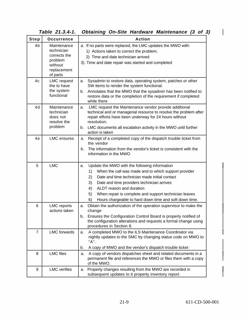
Table 21.3.4-1. Obtaining On-Site Hardware Maintenance (3 of 3) S t e p Occurrence Action
4b Maintenance technician corrects the problem without replacement of parts
a. If no parts were replaced, the LMC updates the MWO with: 1) Actions taken to correct the problem. 2) Time and date technician arrived
3). Time and date repair was started and completed
4c LMC request the to have the system functional
a. Sysadmin to restore data, operating system, patches or other SW items to render the system functional.
b. Annotates that the MWO that the sysadmin has been notified to restore data or the completion of the requirement if completed while there
4d Maintenance technician does not resolve the problem
a. LMC request the Maintenance vendor provide additional technical and or managerial resource to resolve the problem after repair efforts have been underway for 24 hours without resolution.
b. LMC documents all escalation activity in the MWO until further action is taken
4e LMC ensures a. Receipt of a completed copy of the dispatch trouble ticket from the vendor
b. The information from the vendor's ticket is consistent with the information in the MWO
5 LMC a. Update the MWO with the following information 1) When the call was made and to which support provider 2) Date and time technician made initial contact 3) Date and time providers technician arrives 4) ALDT reason and duration 5) When repair is complete and support technician leaves 6) Hours chargeable to hard down time and soft down time.
6 LMC reports actions taken
a. Obtain the authorization of the operation supervisor to make the change
b. Ensures the Configuration Control Board is properly notified of the configuration alterations and requests a formal change using procedures in Section 8.
7 LMC forwards a. A completed MWO to the ILS Maintenance Coordinator via nightly updates to the SMC by changing status code on MWO to "A".
b. A copy of MWO and the vendor's dispatch trouble ticket
8 LMC files a. A copy of vendors dispatches sheet and related documents in a permanent file and references the MWO or files them with a copy of the MWO.
9 LMC verifies a. Property changes resulting from the MWO are recorded in subsequent updates to it property inventory report.
21-9 611-CD-500-001

21.3.5 Return-to-Depot Support
In some cases the OEM does not provide on-site maintenance. Instead, return-to-depot maintenance support is provided whereby an advance replacement LRU is requested from the vendor by the LMC prior to returning the failed repair. If advance replacement is not provided, then the LMC must return the failed item to the appropriate repair center using procedures contained in Section 21.4-2. Work flow process charts C and D located at the end o f this chapter illustrates the flow of Returned to Depot for Service and Equipment Advance Replacement.
Table 21.3.5-1. Procedure for Obtaining Return to Depot Service S t e p Occurrence Action
1 LMC contacts a. The appropriate hardware maintenance provider, using information from the ILS WEB page (reference Section 21.2.1 COTS Hardware Maintenance Contract Database).
2 LMC requests a. Advance replacement LRU from the appropriate hardware maintenance provider with shipping instruction prior to returning the failed repair.
b. Annotate the expected delivery time, RMA #, and carrier information failed item PN, SN EIN's and action as they become available in the MWO
3 LMC receives a. New LRU with RMA authorization.
4 LMC packs a. The failed LRU using the carton containing the new item following instructions received with the advance replacement part.
b. Remove the NASA Property sticker, (silver in color) (also called EIN Tag number) for destruction prior to packing the item for shipment and annotates in MWO.
5 LMC applies a. Address label furnished with advance replacement to the carton
6 LMC enters a. RMA number to the carton containing the part to be returned (if not already entered on the address label) in the MWO.
7. LMC packs a. The box with the failed item and states a brief description of the problem ion the package
8 LMC annotes a. The MWO with RMA# date shipped to vendor and expected receipt or return of item with a description of the problem
b. Update Inventory changes to the hardware in the MWO when the receives and reinstalls the repaired unit
c. Forwards the MWO to the ILS MC by entering status code “A” on the MWO.
d. When he receives the repaired unit and reinstalls the unit with all the date information.
21-10 611-CD-500-001

Table 21.3.5-2. Procedure Equipment Advance Replacement S t e p Occurrence Action
1 LMC request a. The appropriate hardware maintenance provider, using information from the ILS WEB page (reference Section 21.2.1 COTS Hardware Maintenance Contract Database) to provide advance replacement if on-site support is not contracted..
2 LMC assures a. MWO is annotated with failed items part number, serial number EIN action as they become available.
3 LMC obtains a. RMA number and shipping instructions from the repair vendor
4 LMC receives a. New advance replacement with RMA authorization and it is received and installed.
5 LMC packs a. The failed LRU using the carton containing the new item following instructions received with the advance replacement part. Remove the NASA Property sticker, (silver in color) (also called EIN Tag number) for destruction prior to packing the item for shipment.
6 LMC applies a. Address label furnished with advance replacement to the carton
7 LMC enters a. RMA number to the carton containing the part to be returned (if not already entered on the address label , date shipped to vendor and expected receipt or return of item
8 LMC logs a. Update information in the MWO (cite RMA # and return address) date shipped to vendor and expected receipt or return of item.
b. Packs the boxes of the failed items and states a brief description of the problem
9 LMC updates a. The MWO status to "A" for Audit with the new information and when he receives returned unit and reinstalls the repaired unit.
21.4 Maintenance Spares
The maintenance contractor performing the maintenance normally provides replacement LRUs. However replacement LRUs will typically be obtained from within the metropolitan area where the DAAC is located, and will seldom be stocked on the DAAC site.
The ECS ILS Office may procure selected maintenance spares to provide a more rapid return to service for failed critical units and to guarantee their availability. These spares are to be used as a last resort and must be replaced quickly. The ECS ILS Office will also procure selected spares for hardware items that do not have contracted on-site maintenance. Project spares may be centrally stocked at the EDF, stored on-site in the DAAC property room, or reside as installed spares in equipment.
Maintenance spares are procured and replenished by the ECS ILS Office using the process identified in Paragraphs 4.6.3 and 4.6.4 of Release B COTS Maintenance Plan, document 613-CD-003-001; and Section 23, Property Administration of the 611 document. Spares allocated to the DAACS will be managed at the DAAC by the LMC using guidance from the above referenced documents and appropriate local DAAC policies and procedures.
21-11 611-CD-500-001

21.4.1 Use of Maintenance Spares
The LMC will control the use of on-site maintenance spares. Centrally stocked spares can be requested from the ILS Maintenance Coordinator using procedures in Section 21.1. Installation of maintenance spares is performed by the LMC (if qualified) or the COTS hardware maintenance contractor under oversight of the LMC, who ensures procedures in Section 21.3 are followed. Work flow process chart E, located at the end of this chapter illustrates the Centrally Stocked Spares
Table 21.4.1-1. Centrally Stocked Spares S t e p Occurrence Action
1 LMC Opens a. An MWO to request a spare with a reason and description of the problem. In the MWO places an "O" as OPEN and sends an email to ILS MC
2 LMC receives a. An email from the ILS MC authorizing the shipment of the spare from the ILS PA .
3 LMC ensures a. Individuals installing and removing the spare must adhere to Electrostatic standards by standing on and antistatic mat with anti static wrist connection with a common grounding
4 LMC receives a. The spare from the ILS PA and ships the failed LRU to the ILS PA or the repair vendor as directed by ILS PA or ILS MC
5 LMC prepares shipping label
a. On the carton prominently displaying the RMA if required. The shipping address may differ from the maintenance contractor’s main address.
6 LMC removes a. Just prior to packing the failed spare for return to factory repair or ILS PA remove the NASA property sticker (silver in color) (also called the EIN tag) for destruction and so note on the MWO.
7 LMC annotates
a. MWO with repair information such as start, end and delay time, part number, serial number of removed/installed items
8 LMC ensures a. System is return to operational status b. System admin will restore data, operating system, patches or
other SW items to render the system functional c. Maintenance vendor will provide additional technical/and or
managerial resources to resolve the problem after repair efforts have been underway for 24 hours without resolution
d. All escalation activity is annotated in the MWO 9 LMC receives a. The spare from the ILS PA or vendor
10 LMC applies a. The new EIN tag number (New NASA Property sticker)
11 LMC updates a. The MWO with the EIN and replacement component information such as start, end and delay time, part number and serial number of item removed/installed and forwards the MWO by entering status code “A”.
21-12 611-CD-500-001

21.4.2 Return of Failed LRUs
The LMC is responsible for the return of failed LRUs to maintenance contractors providing advanced replacement depot maintenance support (e.g., systems under return-to-depot support). In such agreements the maintenance provider sends to the site a replacement for a failed component under the condition that the site will return the failed component within a reasonable time, usually not greater than 10 days. If the failed component is not returned the contract is charged the full purchase price for the item not returned.
Table 21.4.2-1. Return of Failed LRU S t e p Occurrence Action
1 LMC contacts a. The appropriate hardware maintenance provider using the information on the ILS web page (see Section 2.1.2.1).
2 LMC returns a. Failed LRU using procedures in table 21.3-4 or if advance replacement support is not provided, the LMC requests an RMA # and shipping address from the maintenance provider.
3 LMC attaches a. A brief description of problem to the failed LRU.
4 LMC removes a. Just prior to packing the failed LRU for return to factory repair, remove the NASA property sticker (silver in color) (also called the EIN tag) for destruction and so note on the MWO.
5 LMC will a. Once RMA # is in hand, arrange for the return for the failed LRU to the specified repair facility.
6 LMC packs a. The failed LRU in a manner that minimizes the chance that the item will be damaged in shipment.
7 LMC prepares shipping label
a. The shipping label will be placed on the carton prominently displaying the RMA. The shipping address may differ from the maintenance contractor’s main address.
8 LMC sends a. Package to specified repair facility.
9 LMC receives a. The repaired or replaced item from the vendor
1 0 LMC applies a. The new EIN tag number (New NASA Property sticker)
11 LMC updates a. The MWO with the EIN and replacement component information and forwards the MWO by entering status code “A”.
21.5 Non-standard Hardware Support
Non-standard COTS hardware support consists of maintenance support outside the PPM (support incurring time and materials charges) or escalated support actions by the maintenance support provider. Work flow process chart F located at the end of this chapter illustates the flow of Time and Material Support.
21-13 611-CD-500-001

Table 21.5-1. Procedure for Time and Material Support S t e p Occurrence Action
1 LMC contacts a. The ILS MC to request for Time and Material support.
2 ILS MC determines
a. If the problem is critical enough to justify Time and Material Support and then give the LMC verbal and written approval to use Time and Material support.
b. Approval may contain a dollar limit, time limit and or approval reference number
3 LMC contacts a. The appropriate vendor for Time and Material support and once the service has been rendered.
b. LMC faxes or email the information on the service call. 4 ILS MC
creates a. Quarterly reports of Time and Material support including funding
used and briefs the CCB on the funds status quarterly..
21.5.1 Escalation of COTS Hardware Support Problem
Hardware support providers have escalation policies based on elapsed time from start of the corrective effort. The escalation policies direct increased management attention and/or resources to the problem, which is relatively invisible to the DAACs. Escalation of a hardware support provider’s efforts that may also be requested anytime the corrective effort is not progressing satisfactorily. The LMC may request escalation by calling the maintenance contractor’s technical support center and providing the case number generated when the problem was first reported. The LMC may request assistance from the ILS Maintenance Coordinator in obtaining a satisfactory resolution by using procedures in paragraph 21.1.
21.5.2 Uneconomically Reparable Equipment
Some equipment items are not cost effective to support through maintenance contracts and are also considered not economically reparable. These items include Wyse terminals, keyboards, and mice. Such items, when support by the maintenance vendor is replaced as part of the contract. When not covered under maintenance contract, they will be replaced by the ILS Office through spare replenishment. However, maintenance spares, because they are Government property, will not be disposed of without the direction of the Government. LMCs will request disposition instructions for these items from the ILS Office. They will not be discarded without specific direction from the ILS Office. The disposition request will be made by the LMC following procedures in Section 23 and Property Management Plan for the ECS Project , document 194-602-OPI-001.
21-14 611-CD-500-001

DAAC HARDWARE PROBLEM REPORTING (A)
YES NO
Software or CM Hardware
HW issue
YES NO
System problem discovered by an operator, SA, NA or any other person
Initial troubleshouting/Diagnostics a. Review error message against the applicable
hw/sw operator manual b. Verify that power, network, and interface cables
are properly connected and functioning c. Run internal systems and/or network diagnostics d. Review system logs for evidence of previously
related problems or configuration changes that may be contributing to the problem
e. Attempt to reboot the system
Problem is resolved?
LMC insures the MWO has the following mandatory items: MWO #; status of “OPEN”; system and part (if involved) PN,
SN, ECS and manufacturer; problem priority and problem specifics; and switchover time if appropriate
LMC enters any unique identification # that cross
references this problem to the TT Problem identified as totally
or partially HW issue
TT forwarded to LMC
Complete a TT using procedures in 611 section 8
Determine type of problem (HW, SW or CM)
Submit TT to review board
A-1
User Service Office is notified of problem
DDTS Trouble Ticket (TT) issued to operator, SA, NA or LMC
TT forwarded to SSO
Problem solved? LMC opens a new MWO in ILM database with status code of “O” for “OPEN”
A
Figure 21.5.2-1. DAAC Hardware Problem Reporting (A)
21-15 611-CD-500-001

On-Site Maintenance Support (B)
YES NO
LMC informs the technician that a copy is need of their dispatch trouble ticket with company name, date/time of
arrival and departure, PN & SN of all equipment removed and/or installed, and a narrative of problem and actions taken.
LMC ensures maintenance contractor’s technician places LRU’s on an antistatic mat when working on them.
LRU’s.
LMC ensures technician places anti-static strap on wrist and connects to a common ground when handling LRU’s that can be adversely effected by an electrical charge.
Upon completion of HW repair, LMC ensures the system is returned to
operational status. If needed, LMC arranges with sysadmin to restore data, operating system, patches or
other SW items to render the system functional.
LMC annotates the MWO with repair information such as start, end, delay
times, PN and SN of removed/installed items
LMC requests that the Maintenance vendor provides additional technical
and/or managerial resources to resolve the problem after repair efforts have been underway for 24hrs without resolution.
LMC documents all escalation activity in the MWO
Is the problem resolved?
If a configuration change is required, the LMC/maintenance vendor will first obtain the
authorization of the operation supervisor to make the change and notifies CCB of the change.
Refer to B-1
B
Figure 21.5.2-2. On-Site Maintenance Support (B)
21-16 611-CD-500-001
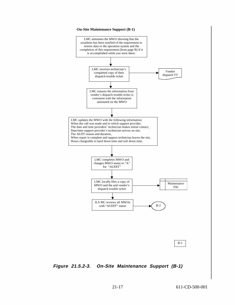
On-Site Maintenance Support (B-1)
LMC ensures the information from vendor’s dispatch trouble ticket is
consistent with the information annotated on the MWO
LMC updates the MWO with the following information: When the call was made and to which support provider, The date and time providers’ technician makes initial contact, Date/time support provider’s technician arrives on site, The ALDT reason and duration, When repair is complete and support technician leaves the site, Hours chargeable to hard down time and soft down time.
ILS MC reviews all MWOs with “AUDIT” status
Vendor dispatch TT
B-2
LMC receives technician’s completed copy of their dispatch trouble ticket
LMC locally files a copy of MWO and the and vendor’s
dispatch trouble ticket
Maintenance File
LMC completes MWO and changes MWO status to “A”
for AUDIT”
LMC annotates the MWO showing that the sysadmin has been notified of the requirement to
restore data or the operation system and the completion of this requirement (from page B) if it
is accomplished while you were there.
“
B-1
Figure 21.5.2-3. On-Site Maintenance Support (B-1)
21-17 611-CD-500-001

On-Site Maintenance Support or Site Depot Support (B-2)
YES NO
YES NO
ILS MC updates the MWO upon receipt of requested information
ILS MC Emails the appropriate LMC requesting
missing information
Is MWO complete and accurate?
ILS MC changes MWO status to “P “ for “PROPERTY”
ILS PA reviews the MWO
ILS PA enters the new part’s information into ILM
Is MWO complete and
accurate?
ILS PA Emails the appropriate LMC requesting
missing information
ILS PA updates the MWO upon receipt of requested information
B-3
ILS PA archives the old part information into ILM
B-2
ILS MC reviews MWO
Figure 21.5.2-4. On-Site Maintenance Support or Site Depot Support (B-2)
21-18 611-CD-500-001

On-Site Maintenance Support or Site Depot Support (B-3)
ECS site’s spare Vendor’s spare
ILS PA changes MWO status to “R” for “RETIRE”
ILS PA assigns the unit dollar to the replacement item and archive
the failed unit at zero dollar.
ILS PA archives the failed part with the same unit dollar value and enters
the new part at its purchase price.
Who provides the replacement?
A completed MWO
ILS PA changes the unit dollar value of the part in the database
B-3
Figure 21.5.2-5. On-site Maintenance Support or Site Depot Support (B-3)
21-19 611-CD-500-001

Equipment Returned to Depot for Service (C)
LMC requests advance replacement LRU with RMA # from repair vendor prior to returning
the failed part
LMC obtains shipping instructions from the repair vendor
LMC annotates MWO with RMA #, date shipped to vendor and expected
receipt or return of item
LMC receives the new LRU with RMA number and packs and boxes of the failed LRU with a brief description of the problem on the package
and MWO
LMC assures MWO is annotated with failed items PN, SN, EIN’s and action
as they become available
LMC removes EIN tag, if appropriate and annotates MWO of this fact
Refer to B-1
LMC completes MWO and changes MWO status to
“A” for “AUDIT”
LMC contacts the hardware maintenance provider , using information from the ILS WEB page performs equipment return
to depot
LMC receives repaired returned unit
LMC reinstalls repaired unit
C
Figure 21.5.2-6. Equipment Returned to Depot for Service (C)
21-20 611-CD-500-001

Equipment Advance Replacement (D)
LMC installs advance replacement part
Advance replacement HW received with RMA# at the AC by LMC
LMC obtains RMA # and shipping instructions from
repair vendor
LMC packs the failed LRU using the carton containing the new item following instructions received from the vendor and after removing EIN
label from the item. Applies the label furnished with the advance replacement to the outside of the carton and annotates the RMA number
on the carton containing the part to be returned. LMC enter on the shipping label the date shipped to vendor, expected receipt of return item
and ships failed item to RMA address
Refer to B-2
LMC updates the MWO with the advance replacement information RMA#, date shipped and expected
receipt date for returned items and then changes MWO status to “A” for
“AUDIT
LMC contacts rhe hardware maintenance provider, using information form ILS WEB page and
requests maintenance vendor to provide advance replacement if on-site support is not contracted
DA
D
Figure 21.5.2-7. Equipment Advance Replacement (D)
21-21 611-CD-500-001

Replacement Item Provided by EDF Centrally Stocked Spares Inventory (E)
YES NO
LMC ensures maintenance vendor’s technician places LRU’s on an antistatic mat when working on them.
LMC ensures technician places anti-static strap on wrist and connects to a common ground when handling LRU’s that can be adversely effected by an electrical charge.
Upon completion of HW repair, LMC ensures the
system is returned to operational status
LMC annotates MWO with repair information such as start, end, and delay times, PN and SN of
removed/installed items and forward the MWO to ILS MC b y entering status code"A"
If needed, LMC arranges with sysadmin to restore data,
operating system, patches or other SW items to render the system
functional
Is the problem resolved?
LMC requests the Maintenance vendor provides additional technical and/or managerial resources to resolve the
problem after repair efforts have been underway for 24hrs without resolution.
LMC documents all escalation activity in the MWO
Refer to B-1
Upon receipt of replacement item, LMC ships failed item to
ILS PA or repair vendor as directed by ILS PA or ILS MC
LMC will receive and EMAIL form the ILS MC authorizing the shipment of the spare
from the ILS PA
LMC annotates MWO with request information and places and "O" for OPEN
and sends an email to ILS MC
LMC open an MWO to request a spare with a reason and description of
problem
Remove the NASA property sticker (silver in color) for destruction and so note on the MWO
E
Figure 21.5.2-8. Replacement Item Provided by EDF Centrally Stocked Spares Inventory (E)
21-22 611-CD-500-001

Time & Material Support (F)
ILS MC determines if problem is critical enough
to justify T&M support
ILS MC receives from LMC a fax or an Email of
services rendered.
Brief the CCB quarterly on T&M
support funds status
LMC provides ILS MC fax or email of service rendered
LMC contacts the appropriate vendor for
T&M support
ILS MC provides LMC with verbal and written approval to use T&M for this specific request. Approval may contain a dollar limit, time limit
and/or approval reference number.
ILS MC creates quarterly reports of T&M support including funding used
ILS MC receives LMC request for T&M support
Refer to B
F
Figure 21.5.2-9. Time & Material Support (F)
21-23 611-CD-500-001

This page intentionally left blank.
21-24 611-CD-500-001

22. COTS Software Maintenance
Software maintenance procedures are current to Drop 5.0 functionality.
22.1 Introduction
The ECS organization provides maintenance and operations for ECS, software, and firmware systems delivered under the ECS contract to the ECS sites. The functions performed by each of the M&O organizations are described in the M&O Management Plan, CDRL 601-CD-001-001. M&O tasks for COTS software support are described in Section 22.1, based on 613-CD-003-001, “Release B COTS Maintenance Plan for the ECS Project” and 194-602-OP1-001, “Property Management Plan for the ECS Project.”
In general, ECS organizations procure, produce, deliver, and document the modifications, and enhancements made to ECS software and firmware. No custom firmware has been identified as part of the ECS program. Commercial off-the-shelf software (COTS SW), firmware, and hardware will be maintained in accordance with the COTS Maintenance Plan, CDRL 613-CD-001001. The Project maintenance philosophy for software is to provide ECS centralized support for developed items and vendor support for COTS SW.
Specific software support procedures are discussed in this section. ECS Project software consists of COTS, custom-developed, and science software. Science software, developed for use on the ECS project, is the responsibility of the science community (see Section 22.1.3). Work f low process chart A illustrates COTS Software License and Maintenance and can be located at the end of this chapter.
COTS software maintenance includes:
• COTS support contract with the software vendor for license to use; telephone assistance in resolving COTS SW problems, as well as obtaining patches and upgrades.
• Services required to produce, deliver, integrate, install, validate and document modifications of existing ECS software and firmware. The maintenance activity includes: software configuration management (CM) including support for change control, configuration status accounting, audit activities, and software quality assurance (QA). Each site is the CM authority over its own resources subject to ESDIS delegation of roles for ECS management.
The site’s LMC, System Administrator (SA) and Network Administrator (NA) will be advised by the ILS Maintenance Coordinator and COTS Software License Administrator on the procedures for handling COTS software upgrades and vendor liaison.
The ECS System Support Office (SSO) provides assistance when COTS software issues exceed the capabilities of the site System Administrator or the Network Administrator to resolve.
22-1 611-CD-500-001

22.1.1 COTS Software Maintenance
Operations personnel at the sites accomplish installation of patches, upgrades and software problem isolation. The COTS software vendors support COTS software procured for the ECS contract. (NB: The term software vendor refers to the company having the legal right to authorize software use and to modify the software code.) COTS software vendor support consists of telephone support for resolution of usage and interface problems, access to an on-line solution database, providing upgrades and patches and resolving COTS software code problems.
The Activity Outline in Table 22.1-1 is an overview of COTS Software Support procedures and the section number where details for performing the tasks can be found. .
Table 22.1-1. COTS Maintenance - Activity Outline Task Section
Assist System Administrator in obtaining COTS SW support
(I) 22
Manage COTS Software Maintenance Contracts (I) 22.1.3
Manage Software Licenses (I) 22.1.4
Interface with CCB (SW License Admin. may go before CCB whenever there is an upgrade in current software version, new patches, or a need to purchase additional software licenses in order to satisfy project requirements. SW License Admin. Should be informed and involved in any overall change to the baseline.)
(I) 22.1.4-22.1.5
Obtain COTS Software Support (P) 22.1.6
22.1.2 Management of COTS Software Maintenance Contracts
The ECS procurement office at the EDF contracts COTS software vendor support. After the first year of warranty support, support is contracted for a period of one or more years and extended or modified as operationally required. Information related to COTS software support contracts is maintained in a database used by the COTS Software License Administrator to monitor the expiration dates and contract terms.
For drop 5A, the COTS SW License Administrator will track software licenses via the Inventory database. As a COTS SW vendor support requirement nears its expiration date, the COTS SW License Administrator determines through consultation with the responsible organization, the need for continued COTS software support. The SW License Administrator will issue a CCR to the CCB organization. When the CCR is approved the SW License Administrator will coordinate with the ECS procurement office for extension/modification of the support contract. Requested changes to COTS SW support contracts should be provided by the site System Administrator to the COTS SW License Administrator. The COTS SW License Administrator may be contacted by email at [email protected] or by dialing 1-800-ECS-DATA, Option #3, then dial extension 5180.
22-2 611-CD-500-001

22.1.3 Management of COTS Software Licenses
Functions of the COTS SW License Administrator include the following:
a. Maintain accountability for all COTS SW licenses procured for the ECS contract. Accountability includes tracking and reporting the as-installed location of all licenses procured. This information will be generated from the findings of the software physical configuration audit. Once the software configuration audit has been performed, the software licenses will be tracked by monitoring the status of COTS SW CCRs as they are implemented and through configuration data maintained in Inventory Database.
b. Assist the SSO organization with the help of the SE/EDS organization in impact analysis of proposed COTS SW upgrades and patches on other COTS SW applications incorporated in the ECS system design. Maintain a database containing license keys of project-purchased COTS SW. The COTS SW installation team (or site) will provide the host identifications to the COTS SW License Administrator, who will then obtain the necessary license keys from vendors for SW installation and populating the COTS SW database.
c. The SSO organization will distribute SW upgrades, with vendor-provided release notes.
d. Keep SSO and all other ECS sites informed by providing them with the vendor maintenance necessary to access vendor patch libraries for use in resolution of software problems.
COTS software licenses vary by the type of software and the software vendors’ policies. COTS software license types include: floating, per site, specific number of concurrent users, unlimited users, and lifetime use without regard to number of users or location. The quantity and type of COTS software licenses initially required are identified to the ECS procurement office by ECS design engineers. COTS software licenses are received and entered into the Inventory Database by the ILS Property Administrator. The ILS Property Administrator maintains the master copy of COTS SW license agreements (hardcopy). The COTS Software License Administrator will update the COTS software license database.
22.1.4 COTS Software Installation and Upgrades
The COTS software upgrades are subject to appropriate CCB approval before they may be loaded on any platform. The SSO Software Librarian, using procedures contained in Section 9, “Configuration Management,” notifies the SSO organization of the upgrades that have been received. The SSO distributes the COTS software upgrades as directed by the CCB. The site System Administrators are responsible for upgrading the software on the host machine and providing follow-up information to the Configuration Management Administrator (CMA), SSO Software Librarian and the COTS SW License Administrator. The site LMC will notify the appropriate personnel when the COTS software is received.
COTS software patches may be provided by the COTS software vendor in response to a DAAC’s call requesting assistance in resolving a COTS software problem. The problem may or may not exist at other locations. When a COTS software patch is received directly from a COTS software vendor (this includes downloading the patch from an on-line source), the DAAC’s CCB shall be informed via CCR prepared by the appropriate site personnel. It is the responsibility of the
22-3 611-CD-500-001

appropriate site personnel to notify the CCB of the patch’s receipt, purpose, and installation status, using procedures contained in Section 9, “Configuration Management,” and to comply with the CCB decisions. The appropriate site personnel will install the COTS SW patches as directed by the CCB. In addition to providing patches to resolve problems at a particular site, the software vendor will periodically provide upgrades of COTS software in order to improve the product. Such upgrades are issued to all licenses covered by a software maintenance contract. Therefore, the COTS software upgrades will be shipped to the ILS PA who receives and enters them into inventory and then forwarded to SSO Software Librarian. The SSO Software Librarian then coordinates with the COTS SW License Administrator to update the software license database once software is installed. When there is a desire to upgrade to a more current version of the software, a CCR must be submitted by the SSO Organization for approval by the appropriate CCB. Once the upgrade is approved and installed, and the CCR closed, the CM Administrator ,ILS PA and COTS SW License Administrator are notified of the configuration change for updating of ECS records. Work Flow process charts B and B-1 illustrate software patches and upgrades and can be located at the end of this chapter
22.1.5 Obtaining COTS Software Support
COTS SW support involves both site capability and contracted support. The site System Administrator (SA), Network Administrator (NA), and site Software Maintenance Engineer provides site capability. The COTS SW vendor provides contracted support. When the appropriate site personnel confirms that a problem is attributed to the COTS SW, the COTS SW vendor’s technical support center is contacted by authorized personnel at the site.
The software vendor’s technical support center will verify contract support authorization and then assist in pinpointing the COTS SW problem to provide a recommended solution. The solution may comprise of a patch, work-around, or include the fix in a future release. If a patch exists to correct the problem, the patch will be identified and provided by the software vendor over the Internet or mailed to the requester. If a patch is required but unavailable, the site and vendor together determine the seriousness of the problem. In cases where the problem is critical, a temporary patch or work-around may be provided. If non-critical, the solution to the software problem may be scheduled by the software vendor to be incorporated in a future update or release. (NB: The DAAC and ESDIS CCBs must authorize the patch to be installed as a permanent installation. This decision may be made after-the-fact. That is, if the patch is needed in order to proceed with operations, notify the appropriate DAAC personnel of the requirement in accordance with Section 9, “Configuration Management.” Applicable requirements of Section 8.1, “Trouble Ticket System Procedures,” must be followed.) LMC at each site will receive the software and log it appropriately in the Software Inventory.
The COTS Software License Administrator obtains the support authorization codes from the vendors and arranges for specified personnel to become an authorized contact person, based upon the limitations imposed by the vendor, and the needs of individual DAACs. The software vendor’s technical support telephone numbers, the names of personnel authorized to contact the vendor, and the authorization codes will be provided to the site’s LMC by the COTS Software License Administrator through the M&O web site entitled “COTS Hardware- Software Maintenance via the following URL"
22-4 611-CD-500-001

http://dmserver.gsfc.nasa.gov/ils/html/maintsw.htm.
Changes to the information in the “COTS Software Support” web site are to be provided to the COTS Software License Administrator as they occur, for updating the web site. Specifically, the need to identify or replace the authorized contact person must be provided by the LMC to the COTS Software License Administrator.
E-mail is the preferred notification method. The site will follow these steps:
a. Send e-mail to [email protected].
b. If e-mail is not available, call 1-800-ECS-DATA, Option 3; then dial extension 0728.
c. Identify the change as either a permanent or temporary change. A temporary change may occur when the authorized contact person is ill, on vacation, in training, or other short-term change of work availability status has occurred or is expected to occur.
d. Provide the COTS Software License Administrator the change information as soon as it is known.
22.1.6 COTS Software Problem Reporting
The first person experiencing or observing a potential COTS SW problem will initiate a trouble ticket according to the procedures found in Section 8.1, “Trouble Ticket System Procedures” then forward it to the assigned site person to review the problem. This person will attempt to isolate the source of the problem to system configuration, hardware, network, COTS SW, custom SW, or science SW.
If it is confirmed to be a COTS SW problem, the authorized contact person should contact the vendor’s technical support center for assistance. Information on contacting the software vendor’s technical support center is in Section 22.1.4.1, “COTS Software Problem Reporting.” The appropriate site personnel must annotate all actions inclusive of dates, time, resolutions, and comments in the Remedy Trouble Ticket as the repair progresses. COTS software corrective action reporting follows the procedures contained in Section 8, “Problem Management” and the configuration control requirements contained in Section 9, “Configuration Management,” when a configuration item is removed and/or replaced with a different version or release.
One method to troubleshooting the COTS SW problem is to scan the software vendor’s web site solutions database to learn of any solutions for similar problems. The software vendor’s web site address can be obtained as stated in Section 22.1.6. Another manner to troubleshooting the COTS SW problem is to exercise any software diagnostic routine embedded or down-loadable that will determine the status of the COTS SW on the equipment by reviewing the troubleshootingdiagnostics and corrective actions taken to date. These troubleshooting, diagnostics, and/or isolation procedures may be contained in the vendor’s operational manuals or in locally devised troubleshooting procedures.
COTS SW problems that cannot be corrected using site and contracted software support may be escalated to the ECS SSO. The SSO is staffed with Senior Systems Engineers knowledgeable on COTS SW that can assist in diagnosing the problem.
22-5 611-CD-500-001

The site Local Maintenance Coordinator may go directly to the software vendor or to the ILS Maintenance Coordinator to obtain an escalation of software vendor support if the software vendor’s efforts have not produced satisfactory results within a reasonable period of time. The escalation may result in increased vendor management review of the problem resolution, the assignment of additional resources to resolve the problem, and/or a more highly qualified technician assigned to resolve the software problem. Work flow process charts D and D1 illustrate Software Problem Reporting and can be located at the end of this chapter.
22.2 Custom Software Maintenance
Multiple baselines may exist throughout the ECS contract. After Version 2, Release 2.0 is operational, the M&O organization may need to modify the configuration as established at each center. The M&O master library was delivered by the release development organization at launch. The Software Change Manager (ClearCase) provides the vehicle to store and maintain the library. The governing policies and minimum developed software component level that may be removed from or reintroduced to (checked-out for maintenance) the master library are defined by the developers’ determination of code modules. This topic is detailed in the description of the Software Change Manager and Baseline Manager (XRP-II) tools, (Sections 9.6 and 9.9 of this document, respectively). Software changes are distributed on the basis of Software Configuration Items to the sites’ copy of the Software Change Manager and recorded in the sites’ copy of Baseline Manager following configuration management procedures defined in the M&O CM Plan (102-CD-001-002) and Section 9 of this document.
Maintenance changes to the ECS baseline may come from any of several sources, e.g.,
• ESDIS CCB directed changes
• Site-level CCB directed changes to Configuration Items (CIs)-- ESDIS will delegate or define which items are to be under site-level control and to what extent those parameters can be changed.
• Developer scheduled modifications or upgrades.
• User or operator initiated Trouble Tickets.
Trouble Tickets (TTs) are written by ECS users, operators, and system administration to address any level of problem they may encounter with a minimum required level of documentation. This topic is addressed in more detail by the ECS Developed SW Maintenance Plan (614-CD-001-002) at section 4.3 and in this document at section 8 “Problem Management.” Most of these problems will be fixed locally with minimum overhead requirements for tracking and analysis. The TT Telecon will be used by the SEO to discuss system-level issues that may
(a) coordinate groups of TTs,
(b) affect more than a single site,
(c) will be referred back to the ESDIS Project Office and the ECS development organization,
22-6 611-CD-500-001

(d) and will be worked-off with the necessary coordination and formality of multi-site change or implementation.
The Software Maintenance Engineer records all actions to resolve a problem on the associated trouble ticket within the TT System tool (Remedy). ClearCase serves as the Software Change Manager, providing utilities to maintain a software master library (the operational baseline) and supporting CM functions for version control. The Software Maintenance Engineer can check-out software components for maintenance and check them in for baselining. The Software Change Manager tracks versions of software used in builds as well as provides a tool to perform builds.
Updates to baselined custom software are submitted with the Version Description Documents (VDD) and go through the CCB review process. The software also goes through M&O testing prior to installation. All changes to the operational baseline are recorded and tracked in the Baseline Manager by the CM Administrator (see Section 9 of this document).
The Activity Checklist table that follows provides an overview of Custom Software Support procedures. Column one (Order) shows the order in which tasks might be accomplished. Column two (Role) lists the Role/Manager/Operator responsible for performing the task. Column three (Task) provides a brief explanation of the task. Column four (Section) provides the Procedure (P) section number or Instruction (I) section number where details for performing the task can be found. Column five (Complete?) is used as a checklist to keep track of which task steps have been completed.
Table 22.2-1. Custom Software Maintenance - Activity Checklist (1 of 2) Order Role Task Section Complete?
1 Software Maintenance Engineer/CMA
Implementation of Modifications (I) 22.2.1
2 SEO Test Plans & Procedures (I) 22.2.2
3 M&O Test Team Custom SW Installation (I) 22.2.3
4 CCB Scheduling the Release (I) 22.2.3.1
5 CMA Operations & User Notification (I) 22.2.3.2
6 SW Maintenance Engineer
Maintenance Changes to the SW Change Manager (ClearCase) Library
(I) 22.2.3.3
7 SW Maintenance Engineer
Creating SW Build Using the SW Change Manager
(I) 22.2.3.4
8 CMA & SW Maintenance Engineer
Promoting SW Using the SW Change Manager
(I) 22.2.3.5
9 SW Maintenance Engineer
Installing the New Release (I) 22.2.3.6
1 0 M&O Team Obtaining SW Support (I) 22.2.4
11 User Services, CMA, Operators
SW Problem Reporting (I) 22.2.4.1
22-7 611-CD-500-001

Table 22.2-1. Custom Software Maintenance - Activity Checklist (2 of 2)Order Role Task Section Complete?
12 Problem Investigator Troubleshooting (I) 22.2.4.2
13 SW Maintenance Engineer
Corrective Action Reporting (I) 22.2.4.3
14 Science SW Team Resolve problems, as required (I) 22.2.5
22.2.1 Implementation of Modifications
Implementation of changes is performed using a controlled build procedure. For each build, each ECS organization selects a responsible engineer (RE). The SEO RE establishes the set of CCRs to be included in the system build. The ECS On-Site, SMC and EOC REs determine which, if any, site-unique extensions are to be applied to the system build. Schedules for implementation, integration, and test at the system and center levels are established. The SEO RE maintains the integrated system and center-specific CCR list and schedule.
The SEO RE maintains the Version Description Document (VDD) that contains:
• The CCRs incorporated into the build and their operational and/or user features
• The build schedule,
• ECS external interfaces affected by the build,
• ECS CIs affected by the build,
• List of ECS documentation (e.g., design documents, procedures, help files, etc.) affected by the build,
• Test program results summary, and
• Test team recommendation.
The initial VDD is provided with Version 2, Release 2.0 by the Independent Acceptance Test Organization. It is then maintained by the Sustaining Engineering Office (SEO) as described in the Developed SW Maintenance Plan, 614-CD-001-003 at Sections 4.3.6 and 4.3.7. It contains not only the as-built documentation, but is supplemented by the as-tested, verified, and accepted documentation as discussed in the Acceptance Testing Management Plan. The document is described in the System Implementation Plan for ECS Turnovers, ECS #301-CD-003-001 which addresses the overall ECS system turnover process (HW, SW, and documents). The SEO RE updates depend on authorized changes.
Appendices are added as necessary to the system level VDD by each center’s RE to describe any center-unique additions/modifications to the build. The VDD is published in draft form well in advance of the build using ECS bulletin boards and electronic distribution. Updates are published as information is gathered. The final VDD is published just prior to installation of the new build into operations.
22-8 611-CD-500-001

For a given CCR, the RE (or designated team) to whom implementation of the CCR is assigned uses the configuration controlled local library to obtain the correct version of the source code/files. Using ECS-provided editors, compilers, and build procedures, the RE implements the change, performs programmer testing, and updates the documentation including design, interface, and procedure documents.
The RE may discover that the approved incorporation schedule cannot be met because of unforeseen complexity, changes in priority, or conflicting assignments. Revised implementations, priorities and schedules are brought to the CCR Telecon for discussion. If necessary, a revised CCR and/or incorporation schedule is forwarded to the ESDIS CCB for impact assessment. Typical CCR discussion topics are outlined in Figure 22.2-1.
CCR Discussion Topics
• Review and prioritize each CCR opened at each center
• Review and re-prioritize older CCRs (as required)
• Review status of open CCRs
• Review distribution of CCRs by organization, status, priority and age
• Recommend new/revised assignments of CCRs to organizations/centers
• Discuss CCR issues with development organizations
Figure 22.2-1. Typical CCR Telecon Agenda
Upon completion of the modification, the revised source files, data bases/ structures, and documentation are impounded and controlled by the Integration and Test organization at the RE’s site using the CM tool. The impounded material is forwarded (if developed at a DAAC, the SMC or EOC) to the SEO for system integration and test. In the case of FOS SW CIs, system integration and test is performed within the EOC.
The golden copy of ECS SW is maintained by the SMC. Required access to the golden copy as well as changes will be guaranteed by logging changes and backing up modifications for later access as required by users, developers, and maintenance personnel under CM guidelines delineated by the ECS CM Plan. SW will also be maintained by local CM at the DAACs.
22.2.2 Test Plans and Procedures
The objective of the test program is to ensure that the CCRs are properly implemented and that defects have not been introduced as a result of the changes. Therefore, both feature (has the CCR been properly implemented) and regression (revalidation of proper operation of the CI and system) testing at both the system and center levels are critical parts of the test program.
The test function exists within each of the M&O organizations. In the larger organizations, individuals may be dedicated to testing of M&O builds. In the smaller organizations, testing may
22-9 611-CD-500-001

be an performed by personnel who have additional assignments. The test team can include maintenance programmers, vendors, users — any personnel who reported the problem that initiated the upgrade or who use the software. Regardless, the guiding principle is that the maintenance programmer who made a change is not allowed to be the only person who revalidates the program or provides feature testing.
The methodology employed in testing includes:
• Inspection — formal verification by examination of the assembled CI and its design documentation.
• Analysis — formal verification by examination and study of the CI/data base/data structure design and coding.
• Demonstration — formal verification by operating the computer program.
• Review of test data — review of test records and data after the execution of the computer program.
These are categories of testing procedures. The specifics cannot and should not be predetermined, but rather should be responsive to the individual requirements determined by the extent/ impact of changes made to the original CI. M&O testing shall consist of recreating in whole or in-part the same scenarios used in the original acceptance testing.
Using the information in the Version Description Document (VDD) described in Section 22.2.1, the system and center test teams develop test plans for the build. The plans describe:
• The CCRs to be tested;
• The CM baseline(s) to be used;
• The requirements and features to be verified;
• The method of verification including identification of test cases/data sets;
• Acceptance criteria;
• Resource requirements; and
• Schedule of testing.
that are to be used for both feature and regression testing. Test procedures provide the detailed scenarios and test cases/data sets, steps, operator/user actions, analyses, etc., that implement the test plan.
Feature testing is performed through either the development of new test cases and data or the modification of existing test cases and data. Regression testing is performed using standard test cases with expected test results. When possible, the same test cases and data as were used when the program was originally developed are used. Test cases developed for prior feature testing are also used as part of the test program.
22-10 611-CD-500-001

When possible, center-specific testing of system-level change builds will be performed in conjunction with the system test. If this is not possible, center-specific testing will precede the system level testing to allow a controlled increase in complexity during the test program. Should center-specific modifications to the system build be required, center level testing will be performed at the center first and then included in either the initial or follow-on system-level testing.
Test results and analyses which are developed by the test organization(s) are provided to the SEO and center REs. Unacceptable performance during the test program may result in delaying of the entire build or removal of a CCR from the build. Because the test team functions as an independent assessment of the build, it provides its recommendation on the quality and performance of the build to the SEO. A summary of the test program and the test team’s recommendation are added to the VDD.
The SEO RE is responsible for review of the test plans and procedures to ensure the adequacy of the test program. Center REs support the SEO RE in this assessment. Status of the test program is also provided to ECS and center management at the weekly status meetings described in Appendix B of the Maintenance and Operations Management Plan.
22.2.3 Custom Software Installation
The Version Description Document (VDD) provides the summary documentation package for each build. The material in the VDD is presented by the ECS M&O test function to the appropriate individual(s) within ESDIS. The VDD material is also presented by the ECS M&O test organization to the appropriate individual(s) within each operational center. If required by ESDIS or the center, results of IV&V or center-unique testing results will be presented by the appropriate organization. Upon review and approval by ESDIS and center management, the build as baselined in the center-specific VDD is authorized for system-wide and center operations.
The following sequence then occurs:
• The VDD undergoes final updates for system and center-specific material identified by ESDIS or the operational centers (e.g., IV&V test results and recommendations, center by center operational installation schedule, etc.).
• The final VDD is published.
• In accordance with the installation schedule, the build is installed at each center along with operational and user documentation updates.
• Controlled Document updates are provided to Document Maintenance and entered into the CM system.
• The CM system is updated to indicate the M&O system and center-specific baselines.
22.2.3.1 Scheduling the Release
Scheduled maintenance should be emphasized as a method of controlling the maintenance function in which the new-release concept already applied to systems is also applied to typical application programs. Emergency fixes are applied as required, but all other repairs or changes are assessed
22-11 611-CD-500-001

for the determination of an appropriate new-release schedule. There are several benefits to this approach:
--By consolidating the changes to be made to a CI, modifications can be performed more efficiently, e.g., documentation is updated only once, minimizes unnecesary disruptions to ops, decreases costs, etc.
--Since users know their changes will not be acted on immediately, they can give more consideration to which changes they actually need.
--Batched changes can be assessed holistically and more thoroughly evaluated.
--Knowing which applications will be maintained during the monthly/yearly cycle enables management to more effectively prioritize maintenance projects
--Positive control of baseline management between the M&O and Development organizations
22.2.3.2 Operations and User Notification
The Version Description Document (VDD) is the vehicle for communicating the contents, status, feature, schedule, and test results to the ECS stake holders. It is supplemented by test plans, test procedures and test results. Draft and final versions of the VDD and test program documentation are published and distributed to interested organizations internal (e.g., the ECS Development Offices, System Management Office, Quality Office, Science Office, etc.) and external (e.g., ESDIS, DAAC, other Customer, external systems, IV&V contractor, SCFs, user groups, etc.) to the ECS Contractor using ECS bulletin boards and electronic distribution.
22.2.3.3 Maintenance Changes to the On-Site SW Change Manager Library
The golden copy of ECS custom software is maintained at the SMC by the SEO CM Administrator. Required access to the golden copy as well as changes will be guaranteed by logging changes and backing up modifications for later access as required by users, developers, and maintenance personnel under CM guidelines delineated by the M&O CM Plan. Custom software will also be maintained by the CMA at the ECS deployment sites.
The Software Maintenance Engineer (SME) will use the Software Change Manager (ClearCase) to maintain the current software baseline. The CMA and SME will maintain the records in Baseline Manager so that they are synchronized with the Software Change Manager maintenance changes.
SMC provides the upgraded or new custom software to the sites. Each site specifies a temporary directory (a ClearCase VOB) that will receive the software. The site CCB must approve the installation of the software into the site's master library.
When notified by the CMA that the source code has been received and baselined, the Software Maintenance Engineer creates branches in the Software Change Manager, which are created for bugfixes, enhancements, and new development that are under CM control. The Software Maintenance Engineer also sets the configuration specification for the operational environment. Lastly, the Software Maintenance Engineer merges the files.
22-12 611-CD-500-001
Refer to the procedures in ECS Work Instruction CM-1-016-1 to manage the branch and merge process.
22.2.3.4 Creating the SW Build Using SW Change Manager (ClearCase)\
Refer to the procedures in ECS Work Instruction CM-1-023-1 to manage creation of the software build using ClearCase.
22.2.3.5 Promoting Software Using SW Change Manager (ClearCase)
Tables of SW states (Table 22.2-2 for ECS SW and Table 22.2-5 for Science SW); valid SW state transitions (Table 22.2-3 for ECS SW and Table 22.2-6 for Science SW); and SW promotion levels (Table 22.2-4 for ECS SW and Table 22.2-7 for Science SW) govern the promotion of ECS custom and science SW from developer or maintenance engineering activities into operational strings. SW Change Manager (ClearCase) scripts execute the transition queries, notification and changes under CM control as explained in Sections 22.2.3.5.1 and 22.2.3.5.2.
22.2.3.5.1 "Change State Script" Description
The Change State script is designed to provide configuration management support of software undergoing change. Software versions will have a state attribute assigned to facilitate the tracking of a version as it proceeds through its lifecycle stages. This script will give its user the capability to change the value of the state attribute of a file version as the version proceeds from one state to another. This script checks the entered state attribute value and allows only valid state values to be processed. It checks the user's identification and allows only designated user(s) to change the state attribute value. It checks to ensure that the entered state value is a valid transition from the file version's current state attribute’s value, informs the user of unexpected transitions, and gives the user the option to proceed with the transition, anyway. It notifies appropriate personnel that the version is ready for system test, acceptance test, or production. It will also assign a state value of ready for supersession and superseded for those versions of files that are being or have been replaced. Valid state values, valid state transitions, personnel authorized to change state values, and personnel to be notified of state changes are stored in files.
22.2.3.5.2 Promotion_level Script Description
The Promotion_level script is designed to provide configuration management support of software undergoing change. Software versions will have a Promotion Level attribute assigned to facilitate the tracking of a version as it proceeds through its lifecycle stages. This script will give its user the capability to change the value of the Promotion Level attribute of a file version as the version proceeds from one promotion level to another. It checks the entered Promotion Level attribute value and allows only valid promotion level values to be processed. Maintenance, system test, acceptance test, and Production are the valid promotion level values. This script also checks the user's identification and allows only designated user(s) to change the promotion level attribute value. It allows the designated user to promote the software version and it sets the initial state
22-13 611-CD-500-001

attribute value for the entered promotion level value. Valid promotion level values and personnel authorized to change these values are stored in files.
Table 22.2-2. ECS Software Oriented Tables State Table State Authority
to Change State
Person to be
Notified
In Promotion
Level
In_Work Developer Maintenance
Ready for Inspection Developer Lead Engineer Maintenance
Inspected Lead Engineer Maintenance
Ready for System Test Lead Engineer Tester Maintenance
In Sys_Testing Tester System_Test
Sys_Tested Tester System_Test
Ready for Acceptance Test Tester Accept. Tester System_Test
In_Accept_Testing Accept. Tester Accept_Test
Accept_Tested Accept. Tester Accept_Test
Ready for Release Accept. Tester
CM_Admin
CM_Admin Accept_Test
Released CM_Admin Accept_Test
Ready for Production CM_Admin Sys_Admin Accept_Test
In_Production Sys_Admin Production
Ready for Supersession CM_Admin, Production
Superseded CM_Admin
22-14 611-CD-500-001

Table 22.2-3. Valid State Transitions
Current State New State
In_Work Ready for Inspection
Ready for Inspection Inspected
Inspected Ready for Sys_Test
Ready for Sys_Test In_Sys_Testing
In_Sys_Testing Sys_Tested
Sys_Tested Ready for Accept_Test
Ready for Acceptance_Test In_Acceptance_Test
In_Acceptance_Test Acceptance_Tested
Accept_Tested Ready for Release
Ready for Release Released
Released Ready for Production
Ready for Production In_Production
In_Production Ready for Superseding
Ready for Superseding Superseded
Superseded (No Transition)
22-15 611-CD-500-001

Table 22.2-4. Valid State Assignment Given Current Promotion LevelPromotion Level State
Maintenance In_Work
Maintenance Ready for Inspection
Maintenance Inspected
Maintenance Ready for System Test
Sys_Test In_Sys_Testing
Sys_Test Sys_Tested
Maintenance
Sys_Test
Ready for Accept_Test
Accept_Test In_Accept_Testing
Accept_Test Accept_Tested
Accept_Test
Sys_Test
Maintenance
Ready for Release
Accept_Test
As_Delivered
Released
As_Delivered
Accept_Test
Sys_Test
Maintenance
Ready for Production
Production In_Production
As_Delivered
Production
Accept_Test
Sys_Test
Maintenance
Ready for Supersession
Production Superseded
22-16 611-CD-500-001

Table 22.2-5. Science Software Oriented State TableState Authority
to Change State
Person to be
Notified
In Promotion Level
in work SDPS/W maintenance
ready for stand-alone test SDPS/W SDPS/W maintenance
in stand-alone testing SDPS/W stand-alone test
stand-alone tested SDPS/W stand-alone test
ready for integrated test SDPS/W SSI&T stand_alone test
in integrated testing SSI&T received by DAAC
integration tested SSI&T received by DAAC
ready for acceptance SSI&T CM_admin received by DAAC
impounded for acceptance CM_admin delivered from SSI&T
ready for production CM_admin delivered from SSI&T
in commissioning CM_admin production
in full production CM_admin production
ready for superseding CM_admin production
superseded CM_admin production
Table 22.2-6. Science Software Oriented Valid State TransitionsCurrent State New State
in work ready for stand-alone test
ready for stand-alone test in stand-alone testing
in stand-alone testing stand-alone tested
stand-alone tested ready for integrated test
ready for integrated test in integrated testing
in integrated testing integration tested
integration tested ready for acceptance
ready for acceptance impounded for acceptance
impounded for acceptance ready for production
ready for production in commissioning
in commissioning in full production
in full production ready for superseding
ready for superseding superseded
superseded (no transition)
22-17 611-CD-500-001

Table 22.2-7. Science Software Oriented Promotion TablePromotion Level Authority to Promote State
from SCF CM_admin or SDPS/W
maintenance SDPS/W (checkout & checkin) in work ready for stand-alone test in stand-alone testing ready for integrated test in integrated testing ready for acceptance ready for production
stand-alone test SDPS/W in stand-alone testing stand-alone tested ready for integrated test ready for acceptance ready for production
received by DAAC SSI&T in integrated testing integration tested ready for acceptance ready for production
delivered from SSI&T CM_admin impounded for acceptance ready for production
production CM_admin in commissioning in full production ready for supersession superseded
22.2.3.6 Installing the New Release
This procedure describes the steps that are executed to perform a SW upgrade on an ECS Host. The personnel involved are Sustaining Engineer (SE), Resource Manager (RM), Production Monitor (PM), and Host Operator (HO). The RM notifies the affected operators that there is an upgrade scheduled and the resources will be coming down for the installation activity. The RM then checks with the production montior to begin unloading the target resources (if Autosys has already scheduled this event, it will happen automatically). The Production Monitor then checks the current load on target resources and informs the RM that the production jobs are complete. The RM then takes the initiative to shut down any processes that may still be running and begins shutdown procedures. Then by monitoring HP OpenView, the RM and SE are notified that the host has gone off-line. The SE uses the install script to install the upgrade, verifies the path and directory structures, and runs all diagnostic tests. The SE then informs the RM that the installation is complete. The RM then initiates the host start-up commands. HP OpenView then indicates that the host is back on line.
The assumptions underlying this procedure are as follows:
(1) The upgrade has been previously scheduled and noted in the resource plan.
22-18 611-CD-500-001
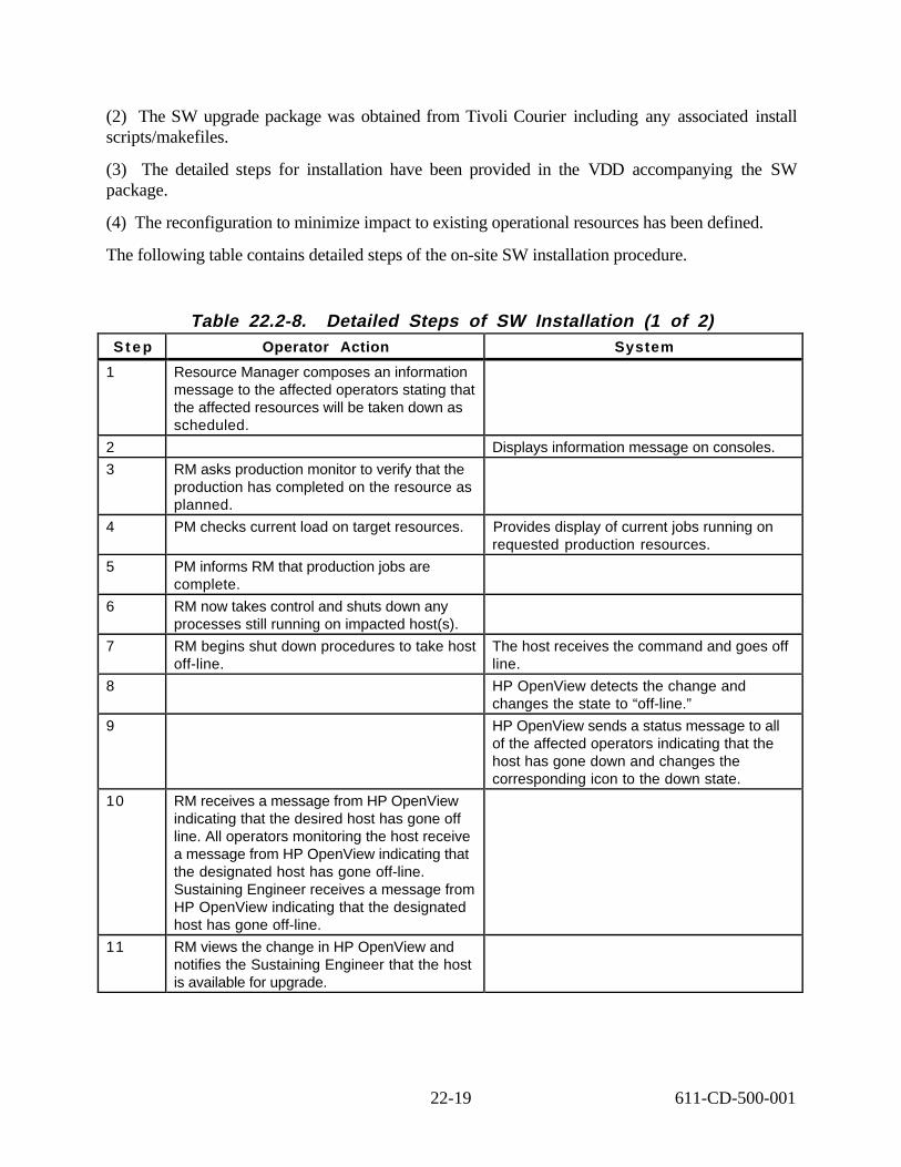
(2) The SW upgrade package was obtained from Tivoli Courier including any associated install scripts/makefiles.
(3) The detailed steps for installation have been provided in the VDD accompanying the SW package.
(4) The reconfiguration to minimize impact to existing operational resources has been defined.
The following table contains detailed steps of the on-site SW installation procedure.
Table 22.2-8. Detailed Steps of SW Installation (1 of 2) S t e p Operator Action System
1 Resource Manager composes an information message to the affected operators stating that the affected resources will be taken down as scheduled.
2 Displays information message on consoles.
3 RM asks production monitor to verify that the production has completed on the resource as planned.
4 PM checks current load on target resources. Provides display of current jobs running on requested production resources.
5 PM informs RM that production jobs are complete.
6 RM now takes control and shuts down any processes still running on impacted host(s).
7 RM begins shut down procedures to take host off-line.
The host receives the command and goes offline.
8 HP OpenView detects the change and changes the state to “off-line.”
9 HP OpenView sends a status message to all of the affected operators indicating that the host has gone down and changes the corresponding icon to the down state.
1 0 RM receives a message from HP OpenView indicating that the desired host has gone offline. All operators monitoring the host receive a message from HP OpenView indicating that the designated host has gone off-line. Sustaining Engineer receives a message from HP OpenView indicating that the designated host has gone off-line.
1 1 RM views the change in HP OpenView and notifies the Sustaining Engineer that the host is available for upgrade.
22-19 611-CD-500-001
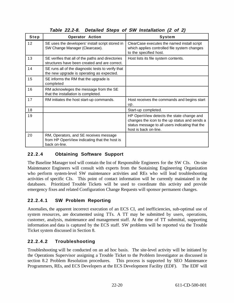
Table 22.2-8. Detailed Steps of SW Installation (2 of 2)S t e p Operator Action System
1 2 SE uses the developers’ install script stored in SW Change Manager (Clearcase).
ClearCase executes the named install script which applies controlled file system changes to the specified host.
1 3 SE verifies that all of the paths and directories structures have been created and are correct.
Host lists its file system contents.
1 4 SE runs all of the diagnostic tests to verify that the new upgrade is operating as expected.
1 5 SE informs the RM that the upgrade is completed
1 6 RM acknowleges the message from the SE that the installation is completed.
1 7 RM initiates the host start-up commands. Host receives the commands and begins startup.
18 Start-up completed.
1 9 HP OpenView detects the state change and changes the icon to the up status and sends a status message to all users indicating that the host is back on-line.
2 0 RM, Operators, and SE receives message from HP OpenView indicating that the host is back on-line.
22.2.4 Obtaining Software Support
The Baseline Manager tool will contain the list of Responsible Engineers for the SW CIs. On-site Maintenance Engineers will consult with experts from the Sustaining Engineering Organization who perform system-level SW maintenance activities and REs who will lead troubleshooting activities of specific CIs. This point of contact information will be currently maintained in the databases. Prioritized Trouble Tickets will be used to coordinate this activity and provide emergency fixes and related Configuration Change Requests will sponsor permanent changes.
22.2.4.1 SW Problem Reporting
Anomalies, the apparent incorrect execution of an ECS CI, and inefficiencies, sub-optimal use of system resources, are documented using TTs. A TT may be submitted by users, operations, customer, analysis, maintenance and management staff. At the time of TT submittal, supporting information and data is captured by the ECS staff. SW problems will be reported via the Trouble Ticket system discussed in Section 8.
22.2.4.2 Troubleshooting
Troubleshooting will be conducted on an ad hoc basis. The site-level activity will be initiated by the Operations Supervisor assigning a Trouble Ticket to the Problem Investigator as discussed in section 8.2 Problem Resolution procedures. This process is supported by SEO Maintenance Programmers, REs, and ECS Developers at the ECS Development Facility (EDF). The EDF will
22-20 611-CD-500-001

have the same SW and computer equipment variants available at the sites. They may be capable of duplicating anomalies experienced in the on-site’s system to derive effective resolutions and/ or work-arounds as required until a permanent resolution is implemented.
At the TT telecon, the TT is prioritized and assigned by the Failure Review Board to an organization for work-off. A Responsible Engineer (RE) is assigned to work-off the TT. Using the captured data, a technical investigation is performed to attempt to isolate the source of the reported anomaly or inefficiency.
If the problem is caused by a non-ECS element (e.g., an interface problem with an external system, poor resource usage by a science algorithm, poor performance by a non-ECS service, etc.), the TT and supporting material is provided to the maintainer of that element. An ECS CCR may also be proposed to protect ECS from potential threats of future problems identical or similar to that documented in the TT. CCRs are discussed in detail at section 9 of this document.
If the TT is properly written against an ECS element, one or more of the following actions are taken:
• Describe the source of the problem and the recommended design/implementation change. Procedure modifications may also be appropriate.
• Modify procedures. Describe the source of the problem and modify procedures to eliminate or reduce the number of occurrences of the documented problem. Modifications may be temporary (i.e., work-arounds) or permanent. If the change is permanent, the TT can be closed and/or a User Recommendations Data Base (URDB) input generated.
• Track. The technical investigation focuses on collection of additional data from new occurrences to support additional analyses into the root of the problem and/or the frequency of occurrence. As a result of tracking, further technical investigations may result in any of the other actions.
• Re-prioritize. Describe the results of the technical investigation and recommend a priority change at the TT Telecon. A lowered priority may result in the TT going into backlog status or being closed. A higher priority may result in additional resources being applied to the technical investigation.
• Close with URDB input. The technical investigation may discover that what is being reported as a problem is actually the proper implementation of the feature based on the requirements baseline. A URDB input documents a recommended requirements change.
• Close TT into existing TT or CCR. If the TT documents a known problem for which no solution has been identified, the new TT can be closed into the existing TT. Supporting material from the new TT is added to that previously collected. The TT may also be closed into a CCR that has been previously written but not yet installed into the operational baseline.
The originator of the TT is kept informed throughout the process via minutes from the TT telecon and voice/ e-mail status reports from the RE.
22-21 611-CD-500-001

22.2.4.3 Corrective Action Reporting
Trouble Tickets will be used to document SW problems as noted in Section 22.2.4.2. The results are tallied against SW Configuration Items to determine critical maintenance concerns related to frequency of occurrence, criticality level, and the volume of problems experienced. The maintainability analysis will guide critical changes, volume and type of support components to be utilized, and focus of further ECS release development.
22.2.5 Science Software
The maintenance of science software and data items provided by the Science Computing Facilities (SCFs) is not the responsibility of the ECS on-site maintenance engineers. Problem resolutions and changes to science software sponsored by the SCFs shall be introduced under the auspices of local DAAC configuration management activities and the Earth Science Data and Information System (ESDIS) (GSFC Code 505) CCB in the same manner as new releases to baselined science software. On-site changes or updates shall be integrated and tested by the Science Software Team. Ongoing CM of ECS integrated science software will be accomplished by the same tool set used for ECS developed software as explained in the Developed SW Maintenance Plan at Section 3.3 Standardization of Support Procedures under local DAAC control.
22-22 611-CD-500-001

COTS Software License and Maintenance
SW Patches/Upgrade License Relocation SW Problem Reporting
Licensing issue identified
Identifier determines type of licensing issue, such as, need for new
licenses, SW upgrade, license movement, or other license
problems.
B Refer to C
Refer to D
A
Figure 22.2.5-1. Licensing
22-23 611-CD-500-001
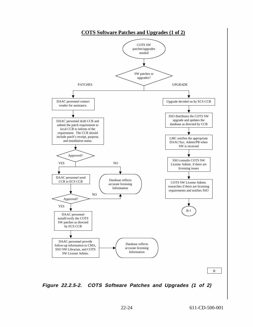
COTS Software Patches and Upgrades (1 of 2)
PATCHES UPGRADE
YES NO
NO
YES
DAAC personnel contact vendor for assistance.
DAAC personnel draft CCR and submit the patch requirement to
local CCB to inform of the requirement. The CCR should
include patch’s receipt, purpose, and installation status.
DAAC personnel install/verify the COTS SW patches as directed
by ECS CCB
LMC notifies the appropriate DAAC/Sys. Admin/PB when
SW is received
Upgrade decided on by ECS CCB
COTS SW patches/upgrades
needed
SW patches or upgrades?
Database reflects accurate licensing
Information
SSO consults COTS SW License Admin. if there are
licensing issues
DAAC personnel provide follow-up information to CMA, SSO SW Librarian, and COTS
SW License Admin.
COTS SW License Admin. researches if there are licensing requirements and notifies SSO
B-1
SSO distributes the COTS SW upgrade and updates the
database as directed by CCB
Approved?
Database reflects accurate licensing
Information
DAAC personnel send CCR to ECS CCB
Approved?
B
Figure 22.2.5-2. COTS Software Patches and Upgrades (1 of 2)
22-24 611-CD-500-001

SSO utilizes the information from the COTS SW License Administrator to revise the CCR
and reviews with the CCB
New license upgrade needed?
SSO Librarian. requests for upgrade media if needed
Approved?
YES
COTS SW License Admin requests from the vendor per the maintenance contract the
upgrade license information and key
YES NO
NO Software hardcopy and Database file reflects accurate information
COTS SW License Admin sends EMAIL to the responsible software engineer with the upgrade license information and key
System Administrator upgrades the SW on the host machine and provides follow-up information to the CMA, SSO SW Librarian, ILS PA and COT SW. License Admin
COTS SW License Administrator updates the software database to reflect new version level
B-1
Figure 22.2.5-3. COTS Software Patches and Upgrades (2 of 2)
22-25 611-CD-500-001

COTS License Relocation/Installation (1 of 2)
License needed
DAAC personnel draft and submit to local CCB a request
for license re-assignment
Approved?
Database reflects accurate licensing
Information
C
DAAC personnel sends CCR to ECS CCB
Approved?
Database reflects accurate licensing
Information
COTS SW License Admin. researches license
requirement
DAAC personnel notify COTS SW License
Admin.
Buy additional licenses?
COTS SW License Admin. purchases additional license and
keys for the SSO to distribute
NO
C-1
YES
NOYES
YES NO
Figure 22.2.5-4. COTS License Relocation/Installation (1 of 2)
22-26 611-CD-500-001

COTS License Relocation/Installation (2 of 2)
Identifier gives information to SW License Admin (machine name, and
host id) license is needed for
License can be moved per an approved CCR from the CCB
COTS SW License Admin contacts vendor for new license assignment
DAAC System Administrator removes license from one host and installs on another, and sends confirmation to SSO, CMA to update the baseline , ILS
PA, to update ILM and COTS SW License Admin to update software hardcopy and database files.
Database reflects accurate licensing
Information
C-1
Figure 22.2.5-5. COTS License Relocation/Installation (2 of 2)
22-27 611-CD-500-001

COTS Software Problem Reporting (1 of 2)
System problem discovered by an operator, SA, NA or any other person
Initial troubleshooting/Diagnostics a. Review error message against the applicable
hw/sw operator manual b. Verify that power, network, and interface cables
are properly connected and functioning c. Run internal systems and/or network diagnostics d. Review system logs for evidence of previously
related problems or configuration changes that may be contributing to the problem
e. Attempt to reboot the system
Problem is resolved?
Complete a TT using procedures in 611 section 8
Determine type of problem (HW, SW or CM)
SSO is notified of problem
DDTS Trouble Ticket (TT) issued to operator, SA, NA or LMC
Person experiencing the problem initiates a TT according to sec. 8 in
611
Refer to Hardware Problem
Reporting Flow Chart
Determine type of SW problem
D-1TT forwarded to SSO
D
YES NO
SOFTWARE OR CM HARDWARE
OTHER SW PROBLEMS COTS SW PROBLEM
Figure 22.2.5-6. COTS Software Problem Reporting (1 of 2)
22-28 611-CD-500-001

COTS Software Problem Reporting (2 of 2)
Problem identified as COTS SW
Site’s authorized personnel contacts COTS SW vendor’s
technical support center
Vendor’s technician provides assistance
The appropriate site personnel must annotate all actions inclusive
of dates, time, resolution, and comments in Remedy TT
Type of resolution
DAAC personnel draft CCR and submit to CCB the requirement. The CCR should include patch’s receipt, purpose, and installation
status.
LMC or DAAC SW Admin. installs the COTS SW patches as directed by the local CCB
Problem fixed?
Database contains accurate
licensing Information
LMC may contact COTS SW License Admin. to obtain
escalation of support effort if the SW vendor’s effort was not satisfactory within a reasonable
period of time LMC or SW Admin. provides follow-up information to CMA, SSO SW Librarian and ILS PA
OTHER RESOLUTION PATCH
YES NO
D-1
Figure 22.2.5-7. COTS Software Problem Reporting (2 of 2)
22-29 611-CD-500-001

This page intentionally left blank.
22-30 611-CD-500-001

23. Property Management
This section describes procedures for the receipt, control, and accountability of ECS property at ECS sites. The “Property Management Plan" 602-CD-001-002 is the base document that addresses the process and policies regarding how ECS property is to be managed. The site Logistics and Maintenance Coordinator (LMC) at each site is the site’s property administrator. LMCs should be thoroughly familiar with and adhere to the contents and policies contained within that document.
The LMCs support the activities of receiving, inspection, storage, issue, inventory recording, accounting, and reporting of ECS property at ECS sites. Generally, LMCs should follow the processes, procedures and policies specified in the Property Management Plan. Locally developed procedures should be forwarded to and reviewed by the ECS ILS Office for consistency with this plan.
23.1 Receipt of Equipment and Software from Vendor
Some equipment, software, consumables, and media will be shipped direct from vendors to the sites. In such cases, the ILS PA will fax a copy of the Purchase Order to the LMC to serve as a due-in notice. Upon receipt of the equipment, the LMC will perform a receiving inspection to verify correctness of delivery, quantity received and to determine if items were damaged during shipment. The LMC will utilize the following tables as guidance for Receipt of Incoming Items.
• Table 23.1-1 for the Receipt of Equipment
• Table 23.1-2 for the Inventory Worksheet
• Table 23.1-3 COTS Non-Conforming Product Report Checklist
• Table 23.1-4 Receiving Process Checklist
The worksheet for documenting inventory as well as the checklists can be located on the Web at http://dmserver.gsfc.nasa.gov/forms/formindex.html under Project forms. Inventory Worksheet form number is Mo05ja99.doc. The Property Checklists form number Mo06ja99.doc, which includes the Loading Dock Checklist, System Verification Checklist and Receiving Process Checklist. The ILS Property Administration (PA) has incorporated these two forms together as one document to reduce paperwork. When all checklists are signed and verified, the LMC will fax or email all forms to the ILS Property Administration for input to the Inventory Database. In addition when a product has a discrepancy or problem the Non-Conforming Product Report (NCR) form located at the same URL with the following form number Mo08ja99.doc can be accessed for use. ). Work flow process charts A, A-1, and A-2 illustrate Receipt o f Hardware/Software, Inventory Worksheet and Non-Conforming Product Reporting and can be located at the end of this chapter.
23-1 611-CD-500-001

Table 23.1-1. Procedure for the Receipt of Equipment
S t e p Action
1. LMC completes the Loading Dock checklist document with the following information: Printed name of receiving individual Signature of receiving individual Date of receipt Name of the carrier Shippers bill of lading or tracking number Customer reference number (when appropriate) Number of boxes received Condition of boxes with a notation of Satisfactory or Damaged
2 Verifies damage, shortage, overage or other discrepancies and annotates these findings on both the carrier’s and site’s copy. An NCR will be completed as listed in Table 23.1-4
3 If damages are noted obtain a signature of the carrier's representative on the shipping carrier's document and notify the ILS PA for further information
4 Begin the process of moving equipment into a controlled storage area and completing the inventory worksheet as described Table 23.1-2
Table 23.1- 2. Procedure for Completion of the Inventory Worksheet S t e p Action
1. LMC removes the equipment from the loading dock to controlled storage area.
2. Verifies the items received against purchase orders and vendor’s packing list. Inspects visual condition of material and documents information on Inventory Worksheet,
3. Documents the serial, model numbers and other appropriate markings on the Inventory Worksheet. Complete visual inspection of product.
4. Assembles equipment for burn-in to be performed for 72 hours and document the burn-in process on the System Verification Checklist.
5. Places silver EIN tags on equipment per the instructions listed in section 23.2
6. Completes the COTS NCR using the procedure in Table 23.1-3.
Table 23.1-3. Procedure for Completion of the Non Conforming Product Report
S t e p Action
1 LMC verifies shipment discrepancies (include shortages, overages, and incorrect items/quantities/models.
2. Completes COTS NCR per instructions on the back of the form
3. Sends the completed COTS NCR to the ILS PA via fax or EMAIL
4. ILS PA sends the NCR form to the appropriate group for vendor notification and resolution.
5. The resolving group will communicate periodic status from the vendor to the ILS PA, who will notify the LMC.
6. The ILS PA will receive the completed NCR from the appropriate group and files in the Property Purchase Order files. The ILS PA will send a copy of the completed NCR via fax or EMAIL to the LMC for their records.
23-2 611-CD-500-001

Table 23.1-4. Receiving Process Checklist S t e p Action
1. Verify that Loading Dock Checklist has been completed with all the appropriate information
2. Annotate Purchase Order number or Returned Material Authorization (RMA) on the Inventory Worksheet.
3. Verify that COTS NCR has been completed and processed, if required as in Table 23.1-3.
4. If the material is partial receipt, verify that it is segregated, labeled, marked and in a controlled storage area
5. If the order has a COTS NCR, verify that it is segregated, labeled and documented in a controlled storage area.
6. Verify the Inventory Worksheet, System Verification, and Receiving Process Checklist have been completed and documented. Fax or Email to the ILS PA
23.2 Receipt of Equipment and Software from the ILS Property Administrator
The LMC will also receive equipment from the ILS PA. Table 23.2-1 defines the process of receiving equipment at the DAACS from the ILS PA and actions required. In addition the ILS PA will be the lead for the COTS NCR. The information listed in Table 23.1-3 explains the process to follow when completing a COTS NCR.
Table 23.2-1. ILS Property Administrator S t e p Action
1. LMC receives shipment with Installation Receipt (IR) report from the ILS PA.
2. LMC inspects and verifies for shipping damage, completeness using the IR report.
3. Notifies the ILS PA immediately of any discrepancies. If discrepancies exist, annotate the IR report accordingly.
4. Sign for the property where indicated and redline location and site specific changes on the top right header information.
5. LMC retains a copy for files and mails the original back to ILS PA
6. The ILS PA enters the redline changes into the ILM Property Database.
7. The original signed redlined IR report and a copy of the Installation Report will be filed in the ECS equipment folder.
8. The site copies of the IR report and installation report will be filed in the site equipment folders
9. The LMC will coordinate installation of the equipment in accordance with approved CCR and DAAC procedures.
23.3 Equipment Tagging
ECS equipment (e.g., contractor-acquired and GFP) that is separately identifiable and meets the criteria for controlled equipment as described in the Property Management Plan 194-602-OP1-001, will be tagged with ECS property tags. Figure 23.2-1 illustrates ECS property tags. The ILS PA prior to shipment will tag ECS equipment reserved at the EDF for staging and subsequent shipment to the sites. Tags will be placed on the equipment so that they are visible and easily accessible by
23-3 611-CD-500-001

bar-code scanners. Vendor-loaned and RSC capital equipment will not be tagged with ECS property tags.
Ce ntrally Re portable Equipme nt Tag
PROPERTY OF NASA/GSFC NAS5-60000
OOOOO126
Equipment Identification Number (EIN)
Figure 23.2-1.
Non-re portable Prope rty Tag
P R
O
PE RT
Y 0F NAS
A/ GS F C
AS5 - 6 0000N
ECS Property Tags (actual size)
Components of major equipment that are not separately identifiable or stocked for use, such as spares/repair parts will not be assigned an EIN. Items not given an EIN sticker will be controlled as inventory items and recorded by manufacturer, description, model/version, serial number (if applicable), location, quantity and with the parent EIN.
Property tags of loaned GFP equipment containing a NASA equipment control number (ECN) will not be removed by the LMC. At the time of receipt of such property, the ILS PA will affix an ECS property tag with EIN next to the government tag. The NASA ECN will be recorded in the property record and cross-referenced to the EIN.
Prior to disposing of ECS equipment, to include transfer to the Government, ECS property tags will be removed. Removed ECS property tags will be retained with the property turn-in document. Turn-in documents will be forwarded to the ILS PA for retention in the property records.
23.4 Property Records and Reporting
The ECS Project will use the Inventory Logistics and Maintenance (ILM) system to support the property management, control and reporting functions for contractor-acquired and GFP equipment. Property records are created and maintained in this system by the ILS PA. LMCs will be able to do queries and prepare reports using the system. Note: Instructions for the use of ILM are in Section 27 of this document.
Property records will contain a line for each item having an EIN (e.g., workstation monitor) and each of its major components (e.g., network interface cards, RAM chips, graphics card). Refer to the IR Report provided at the time of site installation. It is the responsibility of the LMC to notify the ILS PA of inventory, configuration, and location changes so that site property records will be maintained current.
23-4 611-CD-500-001

23.4.1 Maintaining Property Records
LMCs will document inventory and configuration changes in local property records within one business day of the change and appropriately notify the ILS PA.
Support documentation for posting changes to property records include the following:
• Installation Receipt Report -- This report is provided by the installation team at the time equipment is installed and is used to record receipts and changes of equipment at the site. It can be used to update site property records with installed location, date, and name of the person accepting receipts. This report is signed by the LMC to acknowledge receipt of equipment at the site.
• Maintenance Work Orders (MWO) -- Prepared by the site LMC to report equipment changes resulting from maintenance or relocation actions (e.g., serial/model changes, component replacements, and relocation/reconfiguration at the site). MWOs are used by the ILS PA to update the ILM property records.
23.4.2 Reporting Loss, Theft, Damage or Destruction
If ECS or GFP property at the site is lost or stolen, the LMC will notify the site security immediately and the ILS PA within one business day. This initial written report will contain all information related to what was lost/stolen, when, where, how, and the circumstances regarding the loss/theft. The final report, due 30 days later, will contain all information required by the ECS Property Management Plan and will be signed by the DAAC Operations Manager. If a report was prepared by local security personnel/police, a copy of the report should be attached to the report.
If equipment is damaged or destroyed through circumstances that indicate inappropriate use, negligence, or improper care, the LMC will likewise notify the ILS PA of the specifics of the damage/destruction and its circumstances via Internet as soon as known.
The ILS PA will review such incidents and report, as required, to the ECS Contracts Manager, who will immediately notify the Government Property Administrator (e.g., DCMAO).
23.5 Equipment Relocation
This section provides instructions for equipment relocation within a DAAC (intra-site relocation); between ECS sites, and between ECS sites and non-ECS sites (inter-site relocation); to a vendor (off-site relocation); and transfer to outside the contract (external transfer). ). Work f low process charts B, B-1, and B-2 illustrate Equipment Relocation and can be located at the end of this chapter.
23.5.1 Intra-site Relocation
Requirements for equipment reallocations within the facility or between facilities at the same site will be processed through the LMC to maintain control and accountability of equipment inventories. A Maintenance Work Order (MWO) should be used to document and forward the relocation request to the LMC. The LMC reviews the request and schedules the relocation when approved by the local management or configuration control board. When completed, the LMC will
23-5 611-CD-500-001

report the location change in the MWO and forward the MWO to the ILS PA by entering status code “A”.
23.5.2 Inter-site Relocation
Inter-site relocation requests require a CCR approved by the ECS CCB. Such requests will identify by EIN and equipment description what is to be moved, where and when it is to be moved, and the reason for the relocation. The losing site LMC will coordinate the relocation resources and schedule with the gaining site and the ILS PA which will document the action in and MWO. Once completed, the gaining site’s LMC will report completion of the relocation to the ILS PA by recording status code “A” in the MWO. The ILS PA will then update the property record with the new location and date of the action. Any loss or damage to the equipment will be reported using the procedure described in Section 23.3.3 when it occurs or is first discovered. Configuration management authorization is required prior to relocating equipment or software between DAACs.
23.5.3 External Transfers
The ECS Contracting Officer must approve transfers of ECS property outside the contract. Upon receipt of written authorization from the ECS Contracting Officer, transfers of ECS property to the Government or to other contracts will be directed in written instructions to the ILS PA. The ILS PA will complete the necessary documentation authorizing the transfer and provide direction to the site LMCs affected.
23.6 Inventories and Audits
LMCs will complete a 100 percent physical inventory of controlled ECS property and GFP at the site at least annually and not later than July 31. Notification of the scheduled date of the inventory will be provided to the ILS PA 45 days prior to the inventory start date. ECS personnel responsible for maintaining property records will not assist in the conduct of these inventories. Inventories will be designed to achieve the following objectives:
• Verify that accountable equipment is still on hand • Confirm or determine current locations and custodial responsibility for equipment and
material • Identify unrecorded equipment which qualifies for control • Locate or identify missing equipment. • Identify unused or under utilized equipment and equipment or material in need of repair
or rehabilitation.
The LMC will, at the time of completion of the annual inventory, forward a copy of the Inventory Reconciliation Report to the ILS PA. The Inventory Reconciliation Report will be signed by the site’s ECS Manager attesting that a 100 percent inventory was conducted and that all equipment is accounted for except for those indicated as not on hand. All discrepancies will be explained.
23-6 611-CD-500-001

23.7 Storage
Access to equipment and software in storage will be limited to authorized personnel and controlled by the LMC. LMCs will ensure that storage areas are kept in a clean, orderly manner. Material will be stored on shelves, in bins or drawers as appropriate, and its storage location entered into the site property record. Special storage areas or controls will be provided for items subject to corrosion, humidity, and temperature. Such items will be inspected semi-annually by the LMC.
23.7.1 Segregation Requirements
Contractor-owned and vendor-loaned property will be segregated from ECS Government-owned property during storage. Unserviceable equipment will also be segregated from serviceable equipment and will be tagged. Unserviceable/reparable equipment will have a yellow tag affixed to it; unserviceable/non-reparable equipment will have a red tag affixed. Unserviceable equipment tags will indicate reason item is unserviceable, date it became unserviceable, parent EIN it came from, and signature of person declaring the item unserviceable.
23.7.2 Stock Rotation
Material designated as “stock,” such as computer tapes, cleaning tapes, CDs, labels, etc., should be used on a first-in, first-out basis. LMCs will notify the ILS PA of its consumable and media requirements at least 90 days in advance of the need date and will not have in stock greater than a 6-month supply. LMCs will consider space available for storing such material prior to placing its order with the ILS PA. Consumable items are recorded as "C" in the ‘type item’ status field of the ILM system.
23.7.3 Physical Security
ECS property will be stored in secured areas where access will be limited to authorized personnel and controlled by the LMC.
23.8 Packing and Shipping
Prior to shipping centrally reportable equipment to the EDF or other ECS sites, the LMC will notify via Email the receiving LMC of the site’s intent to ship. This will include the expected shipment date, carrier, shipping document number, estimated weight and cube, number of pieces, shipper and ship-to-address. Prior to shipment, a pre-shipment inspection will be performed to verify the following:
• Correct identification of equipment on packing lists and shipping documents including configurations, serial numbers, number of containers, and ship-to address.
• Adherence to packaging and marking standards. • Inclusion of appropriately prepared documents within shipping containers. • LMC will notify the ILS PA via Email or phone when the item shipped has been
received.
23-7 611-CD-500-001

ECS property being shipped from vendors and the EDF will be shipped to the DAAC facility to the attention of the ILS Logistics and Maintenance Coordinator. Local policy at some sites may require delivery to a site central receiving point. In such cases, written procedures will be developed between the LMC and the site’s central receiving office regarding notification of receipts, documentation required, and provisions for local delivery to the DAAC facility. The delivery of ECS equipment to site central receiving points versus direct delivery to the DAAC facility will be determined based on agreements and procedures established between the host facility and the DAAC.
23.9 Electrostatic Discharge (ESD) Program
An Awareness program on Electrostatic Discharge (ESD) and operations and maintenance practices will be followed to eliminate ESD hazards to HW, SW, or people. Procedures for the program will be developed using DOD-HDK-263 and DOD-STD-1686 as guides. Included in the program will be policies and procedures for prevention and safe dissipation of static electricity: Workplace common grounding requirements; and parts handling and protection when in storage, outside the manufacturer's protective packaging, and being readied for installation or removal and packaging for delivery. ESD hazard awareness and prevention will be an appropriate part of the training and certification process of ECS operations and maintenance personnel. All ESD hazard awareness and prevention requirements will be passed through as requirements to all operations or maintenance subcontractors.
23-8 611-CD-500-001

Receipt of Equipment and Software from VendorÄ
YES NO
LMC receives a copy of the purchase order from ILS PA to serve as a due-in notice.
LMC completes the loading dock checklist document with the following information: ⟨ Signature of receiving individual ⟨ Date of receipt ⟨ Name of carrier ⟨ Shippers bill of lading or tracking number ⟨ Customer reference number (when appropriate) ⟨ Number of boxes received ⟨ Condition of boxes with a notation of satisfactory
or damaged
Is there a discrepancy?
A-1 Refer to A-2
A
Figure 23.9-1. Receipt of Equipment and Software from Vendor
23-9 611-CD-500-001

Procedure for Completion of the Inventory Worksheet
LMC removes the equipment from the loading dock to controlled st orage area.
LMC verifies the items received against purchase orders and
vendor‘s packi ng li st.
LMC documents t he SN, model #, and other appropriate markings on the
Inventory Worksheet.
LMC inspects visual condition of material and documents information
on Inventory Worksheet.
ECS Equipment GFP Equipment Spares/Repairs
A-1
LMC assembles equipment for burn-in to be performed for 72 hours and documents
the burn-in process on t he System Verification Checklist.
Do not remove NASA‘s ECN. LMC places the silver EIN t ags
next to the NASA‘s ECN
LMC determines the type of equipment, such as ECS equipment, GFP equipment, or spares/repairs.
C ontrol these inventory items and recorded by manufacture,
description, model/version, SN (if appropriate), location, quanti ty with
parent EIN
Items that are not separately identifiable or stocked for use,
will not be assigned an EIN tag otherwise they are assigned an
EIN Tag
LMC places a silver EIN tag on the new
equipment so that it is visible and easily
accessible by bar code scanners.
Complete t he Inventory Worksheet
A repaired item is assigned a new silver EIN tag
Figure 23.9-2. Procedure for Completion of the Inventory Worksheet
23-10 611-CD-500-001

Procedure for Completion of the Non Conforming Product Report (NCR)
LMC annotates the discrepancies on both the carrier’s and site’s copy
LMC obtains a signature of the carrier’s representative on the shipping document.
LMC completes COTS NCR per instructions on
the back of the form.
LMC sends the completed COTS NCR to the ILS PA via fax or
ILS PA sends the COTS NCR form to procurement for vendor
notification and resolution
ILS PA sends a copy of the completed NCR via fax or email to the LMC for their records.
LMC files the NCR in the appropriate files
A completed COTS NCR
ILS PA notifies LMC periodically of the status until NCR is complete
A-2
Figure 23.9-3. Procedure for Completion of the Non Conforming Product Report (NCR)
23-11 611-CD-500-001

B
Equipment Relocation (1 of 3)
Intra œSite Inter-Site External-Transfer
Equipment relocation requested
Requester determines the type of relocation, such as: an Intra-site relocation, an Inter-site relocation, or an External Transfer (outside
the ECS control
Requester opens a new MWO in the ILM
database to request the relocation to the LMC.
Inter-site relocation requests require a CCR approved by the ECS CCB. The CCR should contain the following information of the item to be relocated: ⟨ EIN, and description ⟨ Where and when it is to be moved ⟨ The reason for the relocation.
Requester obtains approval from the ECS Contracting Officer to transfer ECS property outside the contract.
Requester sends the written Instructions to
the ILS PA.
Requester receives a written authorization from the ECS
Contracting Officer.
Once completed, the gaining site LMC reports the completion of the
relocation by changing the MWO‘s status to —A“ for —Audit“
The losing site LMC will coordinate the relocation resources and schedule
with the gaining site LMC and document the action in the MWO
R equester sends the approved CCR to the LMC.
When completed, LMC will report the location change in the MWO and changes the MWO‘s
status to —A“ for —AUDIT“
LMC reviews the request and schedules the relocation when
approved by local management or configuration control board.
ILS PA will complete the necessary documentation
authorizing the transfer and provides direction to the site
LMCs affected
B-1
Figure 23.9-4. Equipment Relocation (1 of 3)
23-12 611-CD-500-001

B-1
Equipment Relocation (2 of 3)
YES NO
YES NO
ILS MC updates the MWO upon receipt of requested information
ILS MC Emails the appropriate LMC requesting
missing information
ILS MC assures MWO is complete
and accurate?
ILS MC changes MWO status to —P — fpr —PROPERTY“
ILS PA reviews the MWO
ILS PA enters the new part information into ILM
Is MWO complete and
accurate?
ILS PA Emails the appropriate LMC requesting
missing information
ILS PA updates the MWO upon receipt of requested information
B-2
ILS PA archives the old part information into ILM
Figure 23.9-5. Equipment Relocation (2 of 3)
23-13 611-CD-500-001

B-2
Equipment Relocation (3 of 3)
A failed part is replaced A failed part is replaced by an ECS site spare by a vendor spare
ILS PA assigns the unit dollar to the replacement item and archive
the failed unit at zero dollar.
ILS PA archives the failed part with the same unit dollar value and enters
the new part at its purchase price.
Change the unit dollar value of the part in the
database
ILS PA changes MWO status to —R“ for —RETIRE“
A completed MWO
Figure 23.9-6. Equipment Relocation (3 of 3)
23-14 611-CD-500-001

24. Installation Planning
The ECS Facilities Plans (DID 302-CD-003-001 to DID 302-CD-008-001) and the Installation Plans developed for each ECS release are the products of the facility and installation planning process. DAAC Facilities Plans are distributed 30 days after each Release Critical Design Review (CDR). These plans identify space, power, and cooling requirements based on design information available at CDR. The Installation Plans are distributed two months prior to installation of equipment at each ECS Release. As such, the Facilities Plan identifies facility preparation requirements and general installation planning that is based on final design information. The Installation Plans provide the detailed planning required by installation teams and the sites to make final preparation for installing Release equipment. Both documents are provided in draft to the DAACs for review and comment prior to publication.
24.1 Responsibilities
Installation planning and coordination is the responsibility of the ILS Installation Coordinator, who is part of the Integrated Logistics Support (ILS) Office within M&O. Using information obtained during site surveys, the Installation Coordinator prepares the Facility Plans and the Installation Plans and coordinates actions needed to prepare for and conduct the installations. DAAC M&O personnel support the Installation Coordinator by providing information to complete the Site Survey Questionnaire; reviewing the Facility Plan and the Installation Plan. They also ensure that site preparations/coordination are completed on schedule; facilitating receipt and installation of the hardware; and accepting installation of the hardware and software by signing the Installation Receipt Report. Work flow process charts A, A-1, and A-2 illustrate Installation Planning and can be located at the end of this chapter.
24.2 Process Description
DAAC site surveys have been previously conducted to obtain DAAC-specific information needed to begin the installation planning process. This information was documented in a Survey Questionnaire prepared for each DAAC and is used in the preparation of the Facility Plans and the Installation Plans. This information, plus design and equipment specifications, is used to prepare the Facilities Plans, which project facility requirements and provide a preliminary plan for the placement of systems within the DAACs. DAACs review this information and provide requested changes, which are considered in the preparation of the Installation Plans.
Two months prior to the installation of hardware, a detailed Installation Plan is produced to identify the planned placement of hardware in the facility and how the hardware will be configured and networked, and to identify site preparations necessary to support the installation. Installation teams use the Installation Plan to install the systems and networks. After the equipment is installed and tested, the installation team leader obtains the DAAC Manager’s signature on the Installation Receipt Reports, which details the locations and equipment that have been installed and networked. Within three weeks following the installation, the Installations Coordinator will update the facility diagrams and network diagram to reflect the as-installed configuration at the site. These diagrams
24-1 611-CD-500-001

are submitted to the ECS CCB and, when approved, becomes part of the operations baseline for the site and are available for viewing on the web. The baselined diagrams are provided to the site in the “As-Built” document provided to the DAAC shortly after the installation of hardware has been completed. It is the responsibility of the LMC to notify the Installation Coordinator as changes to the baseline documentation occur.
Table 24.1-1. Installation Planning Activity Outline S t e p Responsible Person ACTION
1 Installation Coordinator Receive a copy of installation survey
2 Installation Coordinator Contact vendors, define and arrange load to be delivered to installation site
3 Installation Coordinator Briefing with DAAC SE and coordinate schedule
4 Installation Team Install hardware based on Installation schedule
5. Installation Team Test equipment
6 Installation Coordinator Update Installation plan with revisions
7 Installation Team Test connectivity of all devices by Pinging
8 Installation Coordinator Update information to the plan and create a As-Built document consisting of SCSI Cable Management Schemme, Floor Plan, VCATS Hardware Report, LAN Cable Management Scheme, Network diagram and the Hardware Diagram
9 Installation Coordinator Sends the As-Built document to DAAC Liaison while creating a CCR for the CCB
10 DAAC The DAAC Liaison should provide any changes, deletions or addition to the As-Built document as quickly as possible.
1 1 Installation Coordinator will revise and submit the CCR to the CCB
12 Installation Coordinator Incorporate changes from CCB
13 Installation Coordinator Send publication to Web Document Control Group
24.3 Maintenance of Facility and Hardware Diagrams
Facility and hardware diagrams reflect the as-installed configuration. The baseline version of these diagrams is maintained by the ILS Installations Coordinator. As changes to these diagrams occur (e.g., relocation of equipment within the site, additions/deletions to the LAN), the LMC will inform the ILS Installations Coordinator by redlining the diagrams. The Installations Coordinator will update the Computer Aided Drawing (CAD) system to reflect the change(s) and provide an updated facility drawing to the site’s LMC. The Installation Coordinator will create a CCR and present the changed documents to the CCB for approval to change the baselined document.
24-2 611-CD-500-001

24.4 Maintenance of LAN Cable Management Scheme
Within three weeks of the completed hardware installation, a LAN Cable Management Scheme is supplied to the DAAC LMC by the ILS Installations Coordinator. This matrix will identify the cable number, type, length, decibel loss rating, and location of cables installed; and will identify the IP addresses of the equipment connected by the cables. The LMC will update this matrix as LAN changes occur and send the changes to the Installations Coordinator. The Installation Coordinator will create a CCR and present the changed documents to the CCB for approval to change the baselined documents.
24.5 Maintenance of SCSI Cable Management Scheme
Within three weeks of the completed hardware installation, a SCSI Cable Management Scheme is supplied to the DAAC LMC by the ECS Installations Coordinator. This matrix will identify the cable number, length, location of cables installed; and will identify the equipment connected to the cables. The LMC will update this matrix as LAN changes occur and send the changes to the Installations Coordinator. The Installation Coordinator will create a CCR and present the changed documents to the CCB for approval to change the baselined documents.
24-3 611-CD-500-001

Installation Process (1 of 3)Ä
Daac Liason reviews the documents and schedule for approval or a request to change and sends to ILS Installation
Coordinator.
ILS Installation Coordinator sends the approved documents and
schedule to the Installation Team
ILS nstallation Coordinator incorporates the
and sends to the Daac Liason
A-1
ILS Installation Coordinator uses the information from the Site Survey, plus design and equipment specifications to prepare the Facility and Installation Plans.
ILS Installation Coordinator provides a preliminary plan of the project facility requirements and placement of systems and schedule to the Daac personnel.
Documents and schedule are approved?
YES NO
Daac Liason sends approval back to ILS Installation Coordinator
DAAC personnel assists with a DACC specific Site Survey stionnaire and sends to the ILS Installation Coordinator.
Ichanges/requests
Que
A
Figure 24.5-1. Installation Process (1 of 3)
24-4 611-CD-500-001

Installation Process (2 of 3)Ä
Installation Team installs the systems and networks at the DAAC based on the Installation Plan and schedule
Installation Team tests the installed equipment at the DAAC
Does the installation work?
After the equipment is installed and tested, the Installation Team's Leader obtains the DAAC Manager's signature on the Installation Receipt Reports.
Installation Team informs ECS Installation Coordinator of the discrepancies and revisions needed..
ILS Installation Coordinator updates information to the plan and creates a As-Build document consisting of the following information SCSI Cable Management Floor Plan Hardware Report Cable Management Plan Network Diagram Hardware Diagram
ILS Installation Coordinator updates the Installation Plan with revisions.
ILS Installation coordinator sends the revised Installation Plan and schedule to the Installation Team
Refer to A-1
A-2
A-1
Figure 24.5-2. Installation Process (2 of 3)
24-5 611-CD-500-001

Installation Process (3 of 3)Ä
Installation Coordinator sends the As-Built document to DAAC
Liaison and creates a CCR for the CCB
DAAC Liaison reviews the As-Built document and provides any changes, deletions or addition to the As-Built
document as quickly as possible
DAAC Liaison sends the revised As-Built document to the ILS
Installation Coordinator.
ILS Installation Coordinator revises the As-Built document to board the floor plan,
cable management plan, hardware diagram and SCSI cable management plan to the
CCB
ILS Installation Coordinator incorporates changes from CCB
ILS Installation Coordinator sends publication to Web Document
Control Group
Installation Completed
A-2
Figure 24.5-3. Installation Process (3 of 3)
24-6 611-CD-500-001

25. COTS Training
The procedures to request COTS training have been developed based on these sources: DID 622 ECS Training Plan DID 611-CD-001-005 ECS Mission Operations Procedure, M&O Certification Plan 626-CD-001-005, Section 3, 4 of the ECS M&O Position Description DID 607-CD-001-002. The ECS System Support Office (SSO) Operations Trainer arranges for COTS training by working with the COTS Training Coordinator, the ILS Manager, as well as the potential students.
The Activity Checklist in Table 25.1-1 outlines the role of the COTS Training Coordinator and the section number where details for performing the tasks can be found.
Table 25.1-1. COTS Training - Activity Checklist Task Section
DAAC’s SMC. SSO, ILS, and ECS Development submit requests for COTS Training
25.1
Forward request to ILS Manager 25.2
Arrange for equipment and classroom space 25.2
Ensure that initial registration will be filled or arrange for cancellation without penalty
25.3
Maintain COTS training records 25.4
Monitor DAAC COTS training budget 25.5
25.1 Requesting COTS Training
The COTS Training Coordinator must request training to initiate the following procedures at least 30 days prior to the desired training date. The procedures are accomplished in the following order:
a. The COTS Training Coordinator requests training using COTS Training Request Format via cc:mail to the ECS (SSO) Operations Trainer, the COTS Training Request Format must include the following information:
• Student(s) name and DAAC representation • Training need • COTS course requested • Dates preferred • Price of COTS course • Manager approving purchase of training • Course location • Duration of course
25-1 611-CD-500-001

b. EDS (SSO) Operations Trainer) verifies that the training request meets the following criteria: • Relates to an ECS M&O function • Relates to COTS product in the ECS system design • Is cost effective and within budget constraints
c. COTS Training Coordinator determines the proposed training details, including the following: • Training vendor • Individual or group training, based on cost effectiveness • On-site or off-site class location • Available vendor training dates
d. (All COTS training must be approved by both the ECS (SSO) Operations Trainer and the ILS Manager prior to procurement.) COTS Training Coordinator forwards the training request to the ECS (SSO) Operations Trainer for approval, once approved by the ECS (SSO) Operations Trainer, it is then forwarded to the ILS Manager. The ILS Manager will either approve or deny the request.
e. COTS Training Coordinator maintains record of approval of training purchase.
25.2 Coordinating COTS Training
If the ILS Manager approves the request for COTS training, the COTS Training Coordinator will provide all vendor training details to the COTS Purchasing Manager. The COTS Purchasing Manager produces the purchase order and provides a copy to the COTS Training Coordinator, who will then order the training from the vendor. The procedures to coordinate training are accomplished in the following order:
a. When approved, the COTS Training Coordinator submits all training details to the COTS Purchasing Manager.
b. The COTS Training Coordinator orders training from the vendor.
c. Purchasing Manager processes the purchase order and provides a copy to the COTS Training Coordinator.
d. The COTS Training Coordinator forwards the purchase order to the vendor to reserve training.
e. The COTS Training Coordinator generates a notice to students that includes training vendor, course, date(s), other relevant information.
f. For on-site training, COTS Training Coordinator makes necessary arrangements for classroom space and equipment configuration; coordinates use of any operational equipment required for course, with on-going operations; forwards site location details to vendor instructor.
g. Students attend training.
25-2 611-CD-500-001

h. Prior to Group COTS training, the COTS Training Coordinator provides students with a COTS Training Evaluation Form, which evaluates the effectiveness of the course. In cases when COTS training is found to be substandard or ineffective, the COTS Training Coordinator contacts the ECS (SSO) Operations Trainer, ILS Manager, and the DAAC or site manager, together they come to a consensus as to whether or not to pursue compensation for the training.
i. Depending upon the decision rendered, the COTS Training Coordinator seeks refund, replacement training seat, or training credit from the vendor.
j. The COTS Training Coordinator maintains training records for the DAACs, SMC. SEO, ILS and ECS Development in accordance with DIDs 622 and 525. Required record fields include: price, student name, vendor name, course name and number, course dates, and location.
k. The (COTS Training Coordinator) will forward a copy of the training record to the ECS (SSO) Operations Trainer in format specified by DID 622.
25.3 Canceling/Rescheduling COTS Training
COTS training vendors generally withhold all or part of registration fees for course seats canceled too close to the start date of training. The deadline for cancellation without penalty varies between vendors, but the maximum deadline is three weeks prior to course start date. In order to preserve ECS COTS training funds, any cancellations of COTS training by ECS personnel must be made before three weeks of the start date to avoid these financial penalties.
• If student(s) need to cancel within this three-week deadline, the (DAAC or site manager) will be responsible for substituting an equally qualified individual to attend the course, and for notifying the COTS Training Coordinator to ensure proper record keeping and registration with the vendor.
25.4 Maintenance of COTS Training Records
The (COTS Training Coordinator) will maintain records of all training accomplished as specified in Training Plan DID-622-CD-001-005. COTS training records are maintained by the COTS Training Coordinator which monitors the allocation of funds and reports back to ECS (SSO) Operations Trainer to adjust the budget. The COTS Training Coordinator will submit training record information to the ECS (SSO) Operations Trainer for DID 625-CD-001-001 as specified in the Training Plan DID 622-CD-001-005.
25.5 Contractor COTS Training Funds Accounting
COTS training funds will be allocated to each ECS M&O organization, based upon staffing levels and functions performed at the site. The COTS Training Coordinator maintains the training budget spreadsheets for each of the DAAC’s, SMC, SEO, ILS and ECS M&O Development Facility. The COTS Training Coordinator updates the spreadsheets as training is complete and submits quarterly balance reports to the ECS (SSO) Operations Trainer for planning purposes.
25-3 611-CD-500-001

While the coordination and purchasing responsibilities for COTS training fall primarily with the ECS COTS Training Coordinator, the ECS (SSO) Operations Trainer will be responsible to the M&O organization for spending the allocated COTS training budget judiciously.
Travel funds are not included in the COTS training budget. These must be secured from the organization to which each student belongs.
25-4 611-CD-500-001

26. Earth Science On-Line Directory Administration
The Earth Science On-Line Directory (ESOD) is a combination of HTML web pages and a number of Common Gateway Interface (CGI) programs that are called from the HTML web pages in order to communicate through the Advertising Server to Data Server and Communications subsystems within the ECS. The web pages provide an interface that allows users to:
• Submit new advertisements- Any user can submit advertisements via the ESOD by filling out an HTML generated form and submitting the request through a CGI program to the Advertising Server. New advertisements are not initially visible to other users. The new advertisements must first be approved through a moderator.
• Moderate (approve) advertisements- Certain users, typically an operator at a DAAC, are designated as moderators. Moderators are given the privilege to review submitted advertisements and approve them. Moderation HTML pages are included as part of the ESOD and are accessible to those users who have been given access.
• Search for advertisements- General users can search for Earth Science related data and services through the web interfaces of the ESOD. Searches can be done in a variety of ways that include wild card text searches.
ESOD provides the Advertising Service interface. It is the medium through which scientists can advertise data and services specific to the Earth Science discipline. ESOD receives entries over the Web from non-ECS users and internal entries from the Advertising Server. The Advertising Server is a background process that interacts with the Advertising database for searching, inserting, and updating advertisements. When inserts, updates, and deletes messages are sent from clients to the Advertising Server, they are sent to the Advertising Server running at the DAAC that has been designated as the “master” site. As a consequence, when an update is made to the Advertising database, those changes are replicated out to the other sites in the system by the Sybase Replication Server causing data to be synchronized across sites.
The Advertising Service accepts four types of entries:
1. non-Web service advertisements,
2. installable service advertisements,
3. signature service advertisements
4. Web service advertisements,
Much of the day-to-day support of ESOD comes from reviewing requests from Web users to add new contributions to the directory. Additionally, the ESOD allows Web users to request modifications to entries already in the directory, or deletion of existing entries. The review process involves ensuring the entries adhere to current content standards. To enable more flexible management, ESOD has a “moderation group”. When a contributor requests a new entry, he/she
26-1 611-CD-500-001

specifies which of the available groups it should go into. The group then determines who is notified of the entry and who is allowed to approve it.
ESOD also permits users to query the on-line directory over the World Wide Web. Through a series of easy-to-use HyperText Markup Language (HTML) pages (also referred to as screens), researchers submit requests to create an entry, update an entry, delete an entry, or register as a provider (moderation group). In addition, users can download an installable advertised service directly to their supported Unix workstations.
NOTE: Special care should be taken to guard against computer viruses when accepting installable advertised services.
Moderation Groups are areas of interest to the ECS community; for example, Air-Sea Interaction and Biological Oceanography. The ESOD Administrator (DAAC System Administrator) assigns a Moderator (Data Specialist) to each Moderation Group. The Moderator reviews contributors' requests, ensuring that all required information is included, and taking into consideration any other requirements established for his or her DAAC ESOD and for the Moderation Group. The Moderator will either accept or reject a request, and ESOD will automatically forward an email to the contributor notifying him or her that his/her request is accepted or rejected.
A variety of security features — such as routers, DCE, Netscape — ensure only authorized access to DCE servers and updates to the IOS database. DCE is the software system that enables ECS components, including Common Gateway Interface (CGI), to access the Advertising Service from a variety of computer operating systems located at different sites. DCE also allows more than one user to access the same Moderation Group at the same time. Access is carefully controlled. Moderators are assigned access through DCE. They operate from workstations with IP addresses authorized through the Netscape Enterprise Server via chained query at the IOS server Security Library which is part of the Access Control List database. The Netscape Enterprise Server Administrator is responsible for maintaining ID filtering. Every moderator must be listed on the DCE resource access control lists, which includes the name of the moderator and level of authorized activity; for example, read and write privileges. The ESOD Administrator maintains Moderation Groups and links them through the group resource to the DCE security system.
On-site M&O is responsible for ESOD Administration and Moderation to ensure that ESOD runs smoothly and that users can access the information they want as well as submit requests to be shared throughout the ECS community. Table 26-1 describes the common operator functions performed using ESOD.
26-2 611-CD-500-001
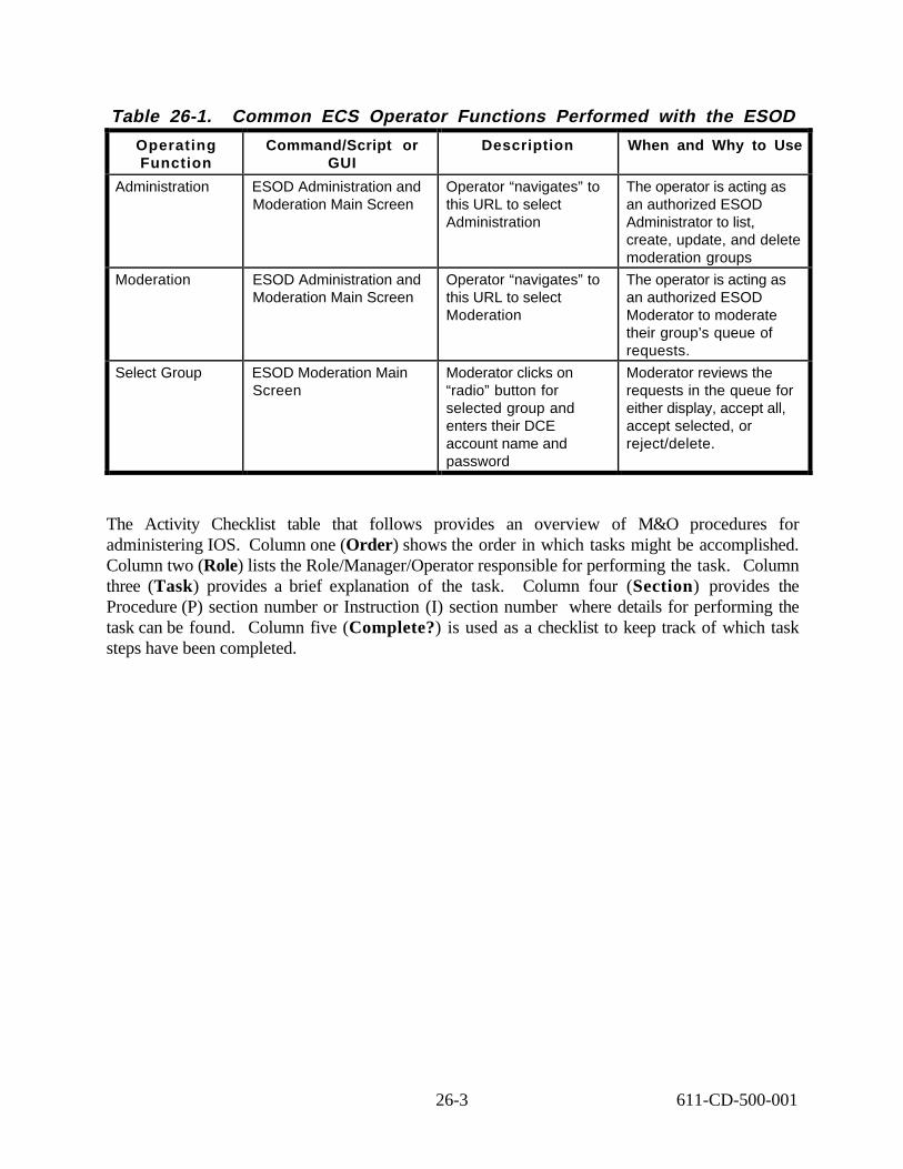
Table 26-1. Common ECS Operator Functions Performed with the ESOD
Operating Function
Command/Script or GUI
Description When and Why to Use
Administration ESOD Administration and Moderation Main Screen
Operator “navigates” to this URL to select Administration
The operator is acting as an authorized ESOD Administrator to list, create, update, and delete moderation groups
Moderation ESOD Administration and Moderation Main Screen
Operator “navigates” to this URL to select Moderation
The operator is acting as an authorized ESOD Moderator to moderate their group’s queue of requests.
Select Group ESOD Moderation Main Screen
Moderator clicks on “radio” button for selected group and enters their DCE account name and password
Moderator reviews the requests in the queue for either display, accept all, accept selected, or reject/delete.
The Activity Checklist table that follows provides an overview of M&O procedures for administering IOS. Column one (Order) shows the order in which tasks might be accomplished. Column two (Role) lists the Role/Manager/Operator responsible for performing the task. Column three (Task) provides a brief explanation of the task. Column four (Section) provides the Procedure (P) section number or Instruction (I) section number where details for performing the task can be found. Column five (Complete?) is used as a checklist to keep track of which task steps have been completed.
26-3 611-CD-500-001

Table 26-2. ESOD Administration - Activity Checklist Order Role Task Section Complete?
1 Moderator (Data Specialist) Approve a Request (P) 26.2
2 Moderator (Data Specialist) Reject a Request (P) 26.2
3 DAAC System Administrator Create Moderation Group (P) 26.3.1
4 DAAC System Administrator Update Moderation Group (P) 26.3.2
5 DAAC System Administrator Delete Moderation Group (P) 26.3.3
26.1 Accessing ESOD
An external user can invoke the Custom Advertising Tool by clicking on the “ESOD icon” from the ECS Desktop or alternatively, via the URL http://<hostname>:<port#>. This will invoke your World Wide Web Browser that supports HTML 3.2 and is Secure Socket Layer (SSL)-enabled, such as Netscape Navigator. The “ESOD Administration and Moderation” Screen will appear.
The moderator can access the moderator page by using the URL http://<host name>:<port #>|IoAdEsodamHome.html.
From most screens, Administration, Moderation, or Help you can return to the ESOD screen by clicking on the appropriate button on the bottom of your screen. Use the navigation bar on the left to go back to ESOD home.
Fields with a red check mark next to them are required fields. Any attempt to perform a function while leaving required fields blank, will result in an error message. The error message will list the fields left blank and request that they be filled in before you can continue.
If you want to return to a previous screen, click on the Back button, at the top left of the screen. Clicking on the Forward button, also at the top left, will take you to the next screen, if you have been there previously.
26.2 ESOD Moderation
An ESOD Moderator reviews each submitted request to create an entry or to modify an existing entry or delete an existing entry. The Moderator will either accept or reject the request. The Moderator can edit the request before he or she accepts it, or leave it in the queue for later action. The Moderator must be on the DCE resource access control list defined for that group. Each action requires that Moderator Verification Information be entered: ECS Username and ECS password. (This is the DCE user name and password.)
To process a request, perform the following:
1 . On the ESOD Administration and Moderation screen, click on “Moderation”.
The Moderation screen appears.
26-4 611-CD-500-001

2 . Click on the button to the left of the Moderation Group whose request list is to be evaluated (moderated). Note that the number of requests to be moderated is provided next to each group name.
3 . Enter Moderator Verification Information:
a. ECS Username
b. ECS Password
4 . Click on Display Requests
5 . If the ECS Username and ECS Password are correct, the “Moderation Queue for “Selected Moderation Group” screen is displayed. These requests are either new submissions for acceptance as entries, or changes to existing entries, or requests to delete entries.
Select the request, and click on Display to review it or use either of “Accept All” or “Accept Selected” or “Reject/ Delete”
The “Moderate … Advertisement” screen appears. The title of the screen includes the type of advertisement displayed.
6 . IF the request is a change to an existing advertisement, you may get the Obsolete screen. This screen lists all other requests which concern the same request that you have selected. Should you accept the selected request, all other requests will be rejected automatically. At this point you can review any of the requests listed and decide whether to continue with your original selection or select one of those listed.
7 . Whether the request is to create a new entry or to modify or delete an existing one, you will access the applicable Moderate screen via the Display.
a. You will see Comments to Moderator, if the Contributor included any; Title; and Description of the entry, if included. You can edit the description field
b. Next, the Moderation Group is identified, having been selected by the Contributor. The field "Valid for another" indicates how long the Contributor has specified that this advertisement will be valid. The Moderator can modify the date. (The system will automatically delete the advertisement on the specified date.) Also on the screen are the Contributor's e-mail address (required) and phone number (optional). The field "Comments to contributor" is the last field to be filled in by the Moderator; for example, to identify cross references to this topic, if any; if rejected, to state that no valid provider exists for this entry; to inform the contributor that this entry is being linked to related entries.
c. At the bottom of the screen, these options are available:
1. Preview request. Moderator can view the request as the user will see it.
2. Save for later review. Save changes and store record for later consideration.
26-5 611-CD-500-001

3. Accept Selected Request. Accept the record and send e-mail to the contributor notifying him or her that the request is accepted; Moderator comments and Advertisement ID are included in the e-mail.
4. Reject/ Delete Request. Delete request and send e-mail to Contributor, notifying him or her that the request is rejected; includes Moderator comments.
5. Reset Form. Cancel changes and store record for later consideration.
d. When the entry is accepted, a screen pops up to notify you that the "Request has been successfully accepted." The Contributor's name and email address are included as well as advertisement ID. A similar screen pops up when you reject the entry.
Table 26-3. ESOD Moderation Quick-Step Procedures S t e p What to Enter or Select Action to Take
1 ECS ESOD icon Click icon
2 Moderation Click folder tab
3 Button for Moderation Group to be evaluated Enter
4 ECS Username Enter
5 ECS Password Click
6 Requested entry Select
7 Display selected request button Click
8 If required, Description field Modify
9 If required, Valid for Another field Modify
1 0 Comments to contributor Enter
1 1 Accept Request button -or- Reject Request button
Click
26.3 ESOD Administration
The DAAC System Administrator as the authorized ESOD administrator can create, update, anddelete moderation groups. The administrator must have a DCE account with write access to theapplicable DCE resource; for example, "ESODAdmin." Each action requires that AdministratorVerification Information be entered: ECS Username and ECS password. (This is the DCE username and password.)
26.3.1 Create a Moderation Group
1 On the ESOD Administration and Moderation screen page, click on Administration.
2 On the Administration screen, click on Create Moderation Group.
3 Fill in the following information:
26-6 611-CD-500-001

a. Name of Moderation group.
b. Description of the group
c. Moderator's name. (The Moderator identified on this screen is the primary moderator. More than one moderator can be identified for the DCE resource access control list. The system is flexible to ensure adequate staff backup.)
d. Moderator's e-mail address (must be current).
e. DCE resource required to moderate the group.
4 Enter Administrator Verification Information:
a. ECS Username
b. ECS Password
5 Click on Submit or Reset Form.
a. Click on Submit to submit the newly created moderation group. A screen will pop up stating that "New moderation group successfully created"; and that the Moderator has been notified, via email, that the group has been created. When the Submit fails, the screen will indicate the reason for failure, such as fields that need information or that such a group already exists.
b. Click on Reset Form to clear the fields.
Table 26-4. Create a Moderation Group Quick-Step Procedures S t e p What to Enter or Select Action to Take
1 ECS ESOD icon Click icon
2 Administration Click folder tab
3 Create Moderation Group Click text
4 Name of Moderation group Enter value
5 Description of Moderation group Enter value
6 Moderator name Enter value
7 Moderator Email address Enter value
8 DCE Resource Enter value
9 ECS Username Enter value
1 0 ECS Password Enter value
1 1 Submit button Click
26.3.2 Update a Moderation Group
1 On the ESOD Administration and Moderation page screen, click on Administration.
26-7 611-CD-500-001

2 On the Administration screen, click on Update Moderation Group.
3 Currently active Moderation Groups are listed.
4 Select the group you want to update and click on the Display Form button. The Update ["Group Name"] screen is accessed.
5 Modify any of the following information:
a. Name of Moderation group.
b. Description of the group
c. Moderator's name.
d. Moderator's e-mail address (must be current).
e. DCE Resource required.
6 Enter Administrator Verification Information:
a. ECS Username
b. ECS Password
7 Click on Submit or Reset Form.
a. Click on Submit to accept the updates. A screen will pop up stating that an e-mail has been sent to inform the Moderator of the changes.
b. Click on Reset Form to cancel the changes.
26-8 611-CD-500-001

Table 26-5. Update a Moderation Group Quick-Step Procedures S t e p What to Enter or Select Action to Take
1 ECS ESOD icon Click icon
2 Administration Click folder tab
3 Update Moderation Group Click text
4 Name of Moderation group Click
5 Display Form button Click
6 Name of Moderation group Enter information
7 Description of subject Enter information
7 Moderator name Enter information
8 Moderator Email address Enter information
9 DCE Resource Enter information
Update the following as required
1 0 ECS Username Enter information
1 1 ECS Password Enter information
1 2 Submit button Click
26.3.3 Delete a Moderation Group
1 On the ESOD Administration and Moderation PAGE screen, click on Administration.
2 On the Administration screen, click on Delete Moderation Group.
3 Currently active Moderation Groups are listed.
4 Select the group you want to delete and click on Display Form.
5 The Delete Modernization Group ["Group Name"] screen is accessed.
NOTE: A warning message tells you the number of entries that will be deleted when you delete the group. Be sure to review the information carefully to be certain you want to delete this group.
6 Enter Administrator Verification Information:
a. ECS Username
b. ECS Password
7 Click on Submit or Reset Form.
a. Click on Submit to delete the group and all associated advertisements and requests. A screen pops up, identifying the record that has been deleted and that a message has been sent to notify the Moderator.
b. Click on Reset Form to cancel the delete.
26-9 611-CD-500-001

1
2
3
4
5
6
NOTE: You will be unable to delete a group if the group has providers in it who are used by other groups. You will have to change the providers (reassign them) and then try to delete the group again.
Table 26-6. Delete a Moderation Group Quick-Step Procedures S t e p What to Enter or Select Action to Take
ECS ESOD icon Click icon
Administration Click folder tab
Delete Moderation Group Click text
ECS Username Enter value
ECS Password Enter value
Submit button Click
26-10 611-CD-500-001

27. Inventory Logistical Management (ILM)
27. 1 XRP-II (Inventory Logistical Management {ILM}) ILM helps the M&O staff at the DAACs, EOC, and SMC to maintain records that describe all inventory components and their assembly structures and interdependencies. The database maintained by this tool, keeps chronological histories (a record of the transactions) of receipt, installation, and relocation of inventory items. ILM limits DAAC staff to accessing only those records, which correspond to equipment at their DAAC.
ILM is a set of automated tools that will assist the Procurement, Property Management, Maintenance, and Logistics teams in managing the tangible property of NASA’s EOSDIS project. ILM is a heavily customized application developed utilizing the commercially available package XRP-II (Product Information and Inventory Management Modules). XRP-II is a manufacturing management system and its customization supports the required capabilities and functions of ILS. The application contains other functions beside the ILM tools. The ECS Management System Main Menu has selections for the Baseline Management tools which is not part of ILM.
XRP-II is a legacy base application. The application consists of a hierarchical menu screen structure and an imbedded COTS database (UNIFY). The hierarchical menu structure is built upon character oriented. Once selected entered or deleted the actions cannot be reversed. In addition XRP/ILM is case sensitive. The vendor has customized the original screens to be ECS specific. The menu screens must be navigated to reach the appropriate ILM function. The lowest level of the structure is a function data screen that displays data and/or accepts data input for the function selected through the menu navigation process. While an operator is logged into the XRP-II program he is engaged in a database session.
Use of the ILM tool involves considerations of the ECS business rules and general logistics concepts as applied on the ECS project. Some basic logistics definitions are provided below.
Each inventory item is identified by a unique Equipment Inventory Number (EIN), and in case of hardware items a physical silver sticker with the EIN is placed on the item. The most significant relationship maintained among inventory items is product structure. Product structure is the XRP-II term for the parent-component pairings that define the ingredients – or bill of material -for an assembly. Product structures have corresponding active and inactive dates that establish the timeframe during which the pairing is in effect. They also facilitate tracking control item changes by a related configuration change request and/or trouble ticket.
27.2 ILM Operator Functions Table 27.1 summarizes the operator functions supported. The sections that follow present how to use the customized features of ILM. Each user/operator is assigned to a work group and the ILM
27-1 611-CD-500-001
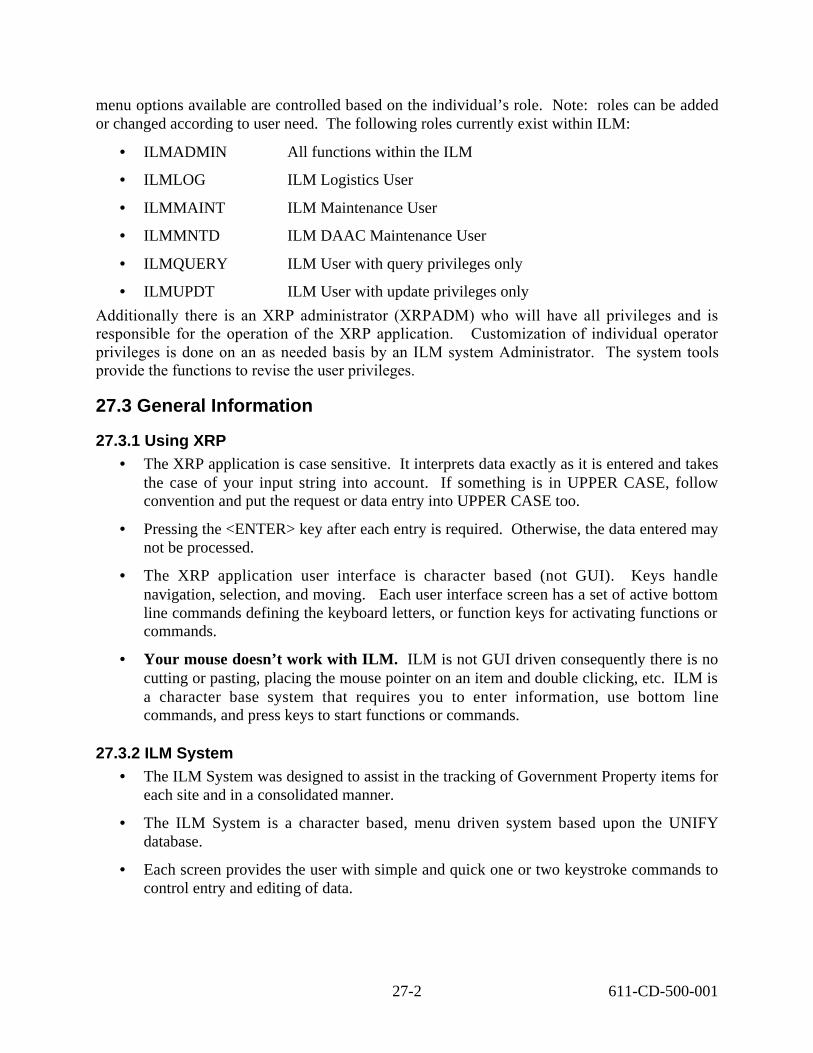
menu options available are controlled based on the individual’s role. Note: roles can be added or changed according to user need. The following roles currently exist within ILM:
• ILMADMIN All functions within the ILM
• ILMLOG ILM Logistics User
• ILMMAINT ILM Maintenance User
• ILMMNTD ILM DAAC Maintenance User
• ILMQUERY ILM User with query privileges only
• ILMUPDT ILM User with update privileges only
Additionally there is an XRP administrator (XRPADM) who will have all privileges and is responsible for the operation of the XRP application. Customization of individual operator privileges is done on an as needed basis by an ILM system Administrator. The system tools provide the functions to revise the user privileges.
27.3 General Information
27.3.1 Using XRP • The XRP application is case sensitive. It interprets data exactly as it is entered and takes
the case of your input string into account. If something is in UPPER CASE, follow convention and put the request or data entry into UPPER CASE too.
• Pressing the <ENTER> key after each entry is required. Otherwise, the data entered may not be processed.
• The XRP application user interface is character based (not GUI). Keys handle navigation, selection, and moving. Each user interface screen has a set of active bottom line commands defining the keyboard letters, or function keys for activating functions or commands.
• Your mouse doesn’t work with ILM. ILM is not GUI driven consequently there is no cutting or pasting, placing the mouse pointer on an item and double clicking, etc. ILM is a character base system that requires you to enter information, use bottom line commands, and press keys to start functions or commands.
27.3.2 ILM System • The ILM System was designed to assist in the tracking of Government Property items for
each site and in a consolidated manner.
• The ILM System is a character based, menu driven system based upon the UNIFY database.
• Each screen provides the user with simple and quick one or two keystroke commands to control entry and editing of data.
27-2 611-CD-500-001

• System administrators have the ability to easily modify screens, menus, and reports to meet changing requirements and individual user needs.
• Included are functions for transferring data between sites and the SMC.
• Reports and screens at the SMC can provide consolidated views of material and requirements.
27.4 Quick Start Using ILM ILM inherited a character-based user interface from the XRP-II application, employs screens for data entry and report generation, and menus for navigating to the screens. Data is entered via the keyboard in fields that are traversed from left to right, row by row. On data entry screens, labels for fields whose values can be modified are displayed in upper case; those that can not be modified have only the first letter capitalized. The database is updated every time a field’s value changes, and a record of that change is written to a transaction log.
Most data entry screens have a form and a table view. Form views offer full screen layouts of a data record’s fields, whereas table views offer rows of records in a window that is panned to see columns of fields. Some screens’ table views, however, contain fewer fields than their corresponding form views. This is caused by system limitations on a table view’s panes.
Numerous functions can be performed on the data entry screens. Commands available to an operator are screen-dependent and are listed near the bottom of each screen (hence their name: bottom-line commands). The more command helps the operator cycle through them. The terminology used can be confusing. “Mode” is used in two different ways: 1) as used in the next paragraph to describe data impact (Add, Insert, or Modify) and 2) the F4-mode of keyboard impact on the selected field in the display.
It is important to note that the UNIFY database management system XRP-II uses does not support rules requiring entries in specific fields. ILM attempts some enforcement via the data entry screens, either by establishing default values where feasible when new records are created, or by blocking an operator from advancing the cursor past a null field when in Add, Insert, or Modify modes. However, database updates can occur in ways that bypass these mechanisms, so operators must ensure required data is entered.
27.4.1 Invoking ILM from the Command Line Interface To invoke the ILM program the operator must be logged in to the appropriate server and beregistered with XRP for the appropriate privileges.To execute ILM from the command line prompt use:
ilmusr
This script solicits the identity of the operator’s workstation. When prompted the operator must provide either the workstation name or its IP address. This information is normally posted on a sticker on the workstation monitor. The script then starts XRP-II, and passes to the operator’s userid it obtained from the system. The screen that is displayed after the XRP-II login is determined by XRP-II based on the user’s ID and password.
27-3 611-CD-500-001

Upon entering a valid userid and password the initial screen for the user will be displayed. The initial screen is associated with a specific userid/password. ILM users will be assigned to Groups according to the role for which their userid/password is valid. ILM privileges are dependent on the Group assignment. ILM privileges include function selections, data modification capability and report selection. The configuration of the initial screen, screen modes, and function selection may result in the display of a data screen that is not exactly as shown in the presentation below.
All ILM menus are similar in appearance and function the same way. Only the titles and selections vary.
Table 27.4.1-1. Procedures to Log into ILM STEP ACTION OCCURRENCE
STEP 1 At the Unix prompt type ‘telnet <XRP server at your site>’
The login prompt will come up.
STEP 2 At the login prompt A. Type in your login name B. Type in your password
STEP 3 A. Type ‘ilm’ and press ‘enter’ B. Type ‘ilmusr’ and press ‘enter’ C. Enter hostname, or IP address of the machine
you are working on, so XRP knows where to display the screen
Depend on the user login the initial screen for the user will be displayed.
Remember to press <ENTER> after each field.
27.5 ECS Management System Main Menu The XRP top-level menu is ECS Management System Main Menu. The userid/password configured initial screen will generally be different for the operator. The ECS Management System Main Menu contains selections that are not ILM functions. Baseline Management is cover in a separate document.
27-4 611-CD-500-001

ECS Management System
[mainm Main Menu 11/07/97 14:2
1. Baseline Management 2. ILM Main Menu
Please enter selection ( 1 -2 or name): ------
F1-help F3-prior menu F5-select F8-exit
Figure 27.5-1. ECS Management System Main Menu
Table 27.5-1. XRP-II menu Function Key bottom commands
F1 Function Key 1 - help Get a description for the highlighted option
F3 Function Key 3 - prior menu Move back to the previous menu
F5 Function Key 5 - select Select the highlighted option
F8 Function Key 8 - exit Exit the tool (XRP-II to the Unix command line)
27-5 611-CD-500-001

ECS Management System
[ilmn ILM Main Menu 11/07/97 14:2
1. EIN Menu 2. ILM Report Menu 3. Maintenance Menu 4. ILM Master Menu
Please enter selection ( 1 -2 or name): ------
F1-help F3-prior menu F5-select F8-exit
Figure 27.5-2. ECS Management System ILM Main Menu
The ILM Main Menu lets the operators navigate to the following submenus:
Table 27.5-2 . ILM Main Menu Functions Menu item Function Section
EIN Menu For adding, modifying, and reviewing the inventory items.
2.1
ILM Report Menu For requesting reports. 2.2
Maintenance Menu For managing the maintenance and work order information.
3.1
ILM Master Menu For managing the ILM parameters and reference information
4.1
27.6 Commands and Functionality The bottom line commands for each menu screen function the same as described for the main menu. Each data screen also has bottom line commands. Generally, the bottom line commands that are invoked with the single letter in bold print. For commands with an “already used” first letter, a slash, “/”, is used as part of the command an example this would be /s command. A period, “.” is used for the third occurrence of a leading letter.
Note that the bottom line commands appearing on any screen are dependent on the user’s attributes. Not all the commands listed for a screen may be appropriate to specific users.
A set of “standard” bottom line commands occurs on nearly all the ILM data screens.
27-6 611-CD-500-001

Other commands may appear on specific screens and are listed in the “Unique Bottom Line Command” section for the function.
While entering data into ILM you may notice that /zoom appears at the bottom of your screen for a given field. This is your indication that a ZOOM list is available to assist you with your data entry selections.
27.6.1 Cursor Motion
The four arrow keys (UP, DOWN, LEFT and RIGHT) are used to move the cursor to various fields of the screen. A number may be entered before depressing an arrow key in order to move to the cursor multiple fields at once. The current number that has been entered is displayed at the bottom left hand corner of the screen. If a DOWN arrow is entered when the cursor is at the bottom of a table view screen, then, assuming there is more data in the file, the screen is redrawn to display the data shifted a half page down. Similarly, the display may be shifted a half page upwards by entering an UP arrow at the top of the screen. Cursor motion via the arrow keys is limited to the current page plus a half-page shift.
27.6.2 Next or Prior
The bottom line “n” (Next) and “p” (Prior), when in the form view (one record on the screen) these commands move the display to the next or prior record. When in the table view (multiple records per screen) these commands move to the next or prior page of records. A number may be entered prior to the command as in “10n” which advances the display 10 records when in the form view or ten pages when in the table view.
27.6.3 View Command
This command toggles the display between the form and table views of the data. The table view shows basic information for several records at once. The form view shows all of the fields of the current record. For records with too many fields to fit across the screen when in the table view, the Left, Right, and justify commands described later may be used to move the display to the left or right.
27.6.4 Find Command
This command is used to find a record based on data entered. Data may be entered at one or more fields of the display and a partial string may be entered. Datalook (is a utility that searches the database for specified information) to clear the screen and allows the user to enter data into one or more fields to find. Pressing “F5” begins the search.
27.6.5 Go Command
The Go command allows the user to go to the First record, Last record, or the specified record number. To use the Go command type ‘g’ for Go. A prompt will come up stating “GO: First, Last, or Record Number, or Quit?” Type in the first letter to specify where to go (i.e. enter ‘f’ for first record). The entry of a number followed by ‘g’ for Go causes the display to shift to the specified record number. For example:
27-7 611-CD-500-001

0g or g or 1g moves to the start of the file 10g moves the cursor to record 10 1000g moves the cursor to record 1000
27.6.6 Select Command
The bottom line ‘s’ (Select) command allows you to select a subset of all the records in order to view, edit, or report on them. Once a set has been selected, the select command may be used again to select a subset of the set.
27.6.7 Selection Criteria
Data may be entered at one or more fields in order to specify the records to be selected. The selection function may be initiated either from the table or form views, but sometimes it is necessary to first switch to the form view if there is insufficient room to enter the desired selection specifications when in the table view.
There are two basic kinds of selection capability:
a . Exact matching, where the user types exactly what the selected records are to contain.
b. Inexact matching, where special characters are entered which are expanded into patterns during the matching process. The inexact matching provisions described below also apply to range fields (i.e. Account Number or Range).
Some examples of inexact matches are numeric and date ranges ( for example, numbers from 1 to 100, dates before 1/1/87, or dates from 3/1/87 to 4/1/87), or substring matching (all the strings that contain the name “Smith”).
27.6.7.1 Exact Matches
To specify an Exact match, simply fill in the field or fields on the screen with the exact data to select for.
27.6.7.2 Inexact matches on String Fields
To specify an inexact match on string fields, use the following special characters.
? The “wild character”. The question mark matches any single character. Thus to find all the Smith’s whether spelled “Smith” or “Smyth”, use the specification “Sm?th”
* The “wild string’. The asterisk matches any string of characters of any length, including zero length strings (also called “null strings”). A * is automatically appended to the end of all string specifications.
[…] The character class framed by the brackets matches any single character that is a member of the class. For example, [apq] matches any of the letters a, p or q. Ranges of characters may be specified by separating 2 characters by a dash (“-“). All upper case letters could be represented by the class [ABCDEFGHIJKL-MNOPQRRSTUVWXYZ] or more
27-8 611-CD-500-001

conveniently as [A-Z]. All letters, upper and lower case together, can be represented as [a-Z]. Other classes can be similarly constructed.
If the string field contains numbers (eg. H0002) and the user wishes to inexact match on a range of these numbers it is important to understand that ranges within strings behave differently than ranges within numeric fields. For example a good range for a numeric field could be 1-9999. This is defined by the system to be all numbers >=1 and <=9999. However, the range of [H00001-H99999] for a string would be defined as all strings starting with the letter H, or the numbers 0 and 9, or characters falling in the range of 1-H. If the user wanted to select all fields of H00001 through H9999, he could use H[09][0-9][0-9][0-9][0-9] if space permits.
27.6.7.3 Inexact Matches on Numeric Fields
Inexact matches on numeric fields, including dates and times, can be constructed by the
Following set of expressions.
>f1 The “greater than” operation. All fields with values greater than the entered value will match.
<f1 The “less than” operation. All fields with values less than the entered value will match. !f1 The logical “not” operation. All fields that do not match the entered value will match. F1-f2 The “range” operation. All field values that match the entered values, or are between the
entered values will match. This is equivalent to >=f1 AND <=f2. !f1-f2 This expression matches all field values that are outside the range of entered values. This
is equivalent to <f1 OR >f2.
Any number of fields on the screen can be filled in as described above. The result is to select from the records of the file those which match all of the entered values. Once a set of records has been selected in this manner, Datalook displays the selected records.
27.6.8 Sort Command
The bottom line “/S” (Sort) command allows the current records to be sorted via any field or fields of the screen. Enter a number (1, 2,…) at each of the fields to be included in the sort, in the order they are to be included. Then press “F5” command to initiate the sort.
If a negative number is entered at a field, that field is sorted in descending order instead of the default ascending order.
27.6.9 Note Command
This command activates a text area for the user to write notes about the displayed screen. The information is retrieve by the same user when in the same screen.
27-9 611-CD-500-001

27.6.10 Add/InsertThese commands are used to add new records. The bottom line “/I” (Insert) command adds anew record or records before the current record while the bottom line “/a” (Add) command addsa new record or records after the current record.
27.6.11 Modify CommandThe bottom line “/m” (Modify) command is used to modify one or more fields of existingrecords. After modifying each field the cursor moves to the next field in the default direction,down in form view, or right in table view. Press “F3” to exit modify mode.
27.6.12 Delete CommandThe bottom line “/d” (Delete) command offers a choice of deleting “line-by-line” or multiplerecords at once. If the “line-by-line” option is selected each entry of a down arrow deletes thecurrent record. If, instead, a number is entered, the logic deletes the specified number of records.
27.6.13 Write, Execute Command
These commands appear only on screens that can drive an executable function. The bottom line “w” (Write) command is used to save the current record of the screen in a file named by the user. This file may then be referenced in a UNIX script that executes the function in BATCH mode. The bottom line “e” (Execute) command is used once the screen data is edited in order to start execution of the underlying function.
27.6.14 Items Command
The bottom line “I” (Items) command appears only on header-line item combination screens, such as are used for Purchase order or Work Order. When on the EIN menu (header record) pressing “I” activates the item screen.
27.6.15 Help Command
The bottom line “h” (Help) command on the main menu provides information concerning the screen, the fields of the screen, or Datalook commands. If the commands option is selected you may enter the letter or prefix plus letter that activates the command to see the help information for that command.
27.6.16 More Command
The “m” (More) command cycles the bottom line prompt through all of the available menuchoices.
27.6.17 Quit CommandThe bottom line “q” (Quit) command exits the screen.
27.6.18 Zoom Command
When the cursor is at a field which is related to data in a different table of the database, the bottom line “/z” (Zoom) command appears at the right of the screen. If the command is
27-10 611-CD-500-001

executed, Datalook opens a window to a different screen which displays the related data. The standard commands (Find, Go, Next, Prior, or arrows) may be used on the data in the window. If the user tags the field (the tag command is described later) and exits the zoom screen, the tagged value is returned to the initial screen. The “/z” (Zoom) option also appears when it is applicable while adding records or modifying fields.
27.6.19 Left, Right, Justify Commands
They allow the data window to be shifted left or right for screens, which have, too may fields to be shown on one page. The bottom line “j” (Justify) command causes the page to start with the current field at the left.
27.6.20 Tag, Untag Command
Tagged fields are used to identify default field values to be used when adding records or copying data into one or more records. If the user enters the “t” (Tag) command when the cursor is at a specified field, the field is tagged. This highlighted field in a manner (such as reverse video, or half intensity, depending on how the screen has been interfaced to the UNIX operating system). Only one field in a specific column of fields may be tagged at a time. A tagged field may be untagged either by entering the “t” (Tag) command again when the cursor is at that field, or by tagging some other field in the same column, or by entering the “u” (Untag) command which untags tagged fields. A tagged field remains tagged whether or not it is on the current screen until it is untagged.
27.6.21 Report Command
The bottom line “/r” (Report) command has a series of submenus which identify the report, its parameters, and the destination of the report. Every database maintenance screen has three builtin reports:
a. a “Table Report” which follows the format of a table view screen, but adds a report header and pagination
b. a “Form Report” which provides a single-page report of the form view for the current record
c. An “ASCII Report” which displays the data in ASCII form without headers and pagination, suitable for loading into a spreadsheet or transmitting to another computer.
27.6.21.1 Selecting Records for Printing
Before printing a Table Report or an ASCII Report, the user may select a subset of records via the Select function. If no preselection has been performed, Datalook displays the numbers of the first and last records in the file and allows the user to accept these as the range of records to be reported on, or to modify them in order to report on a subset of the records. The first page of a table report shows the criteria used to select the records.
27-11 611-CD-500-001

27.6.21.2 Column Selection
On Entering the Report Command, the user has the option of specifying the columns and the order in which they should be printed in a Table Report. If you do not specify the columns, the report starts with the left-most field screen and includes as many columns to the right as specified. The left-most field of the report may be controlled via the Left, Right, and Justify commands.
27.6.21.3 Report Format
The default ASCII Report format consists of data in ASCII form with fields separated by pipe (|) symbols. To generate a formatted report on a subset of the records, execute the select function before executing report.
27.6.21.4 Report Destinations
Once a report has been specified, Datalook offers the user a choice of report destinations. These choices may be 1) screen, 2) file, or 3) local printer.
If the report is not being sent to the screen, the user can specify whether or not it is to be run in background.
Once a report and destination have been chosen, the logic verifies that the width of the report is supported by the destination. If necessary, it retrieves the control characters necessary to put the output device into a mode such that it can support the width. If the report is too wide for the maximum width supported by the output device, the user is cautioned and may alter the destination or choose to proceed regardless.
27.7EIN Menu Options provided on this menu allow the operator to navigate to a set of screens for accessing the inventory information.
ECS Management System [einmainm] EIN Menu 11/07/97 14:04
1. EIN Structure Manger 2. EIN Manager
Please enter selection ( 1 - 2 or name): ------
F1-help F3-prior menu F5-select F8-exit
Figure 27.7-1. EIN Menu
27-12 611-CD-500-001

NNN PP VV FF GG SS //SSS //NNN CC II HH MM QQ
The EIN menu is broken down into the following functions. (Please note) The arrangement of this screen will appear different in ILM but the content within the selections will remain the same.
Table 27.7-1. EIN Menu options Menu item Function Section
EIN Structure Manager This screen is designed to allow the appropriate personnel at each DAAC to view their Inventory
2.1.1
EIN Manager This screen is designed to allow each individual DAAC inventory the configuration of machine and its children
2.1.2
The following pages describe the screens, the data, and the process for reviewing EIN Controlled items data. Each selection item on the EIN menu is discussed, in the order on the menu screen. This discussion includes sub menus, screens, and automatic triggers, if any, associated with the individual screen or field.
27.7.1 EIN Structure Manager
This screen is designed to display structure for a machine and items attached to it. This screen will only be presented to the user in INQUIRY mode. All changes to the database via this screen are reserved to the ILS Property Administrator and will not be active at the DAAC's.
[einstrct] EIN STRUCTURE MANAGER: Last: 2655 Current: 1
PARENT EIN: 00000000 Engineering Change: 00000000
OEM Part: +KTH4P/8OEM Desc: 8 MB RAM for HP Laser jet 5SIECS Name: 10mss01
Installation Report: 1188 Ship Report: 10794
PO NUMBER: OR
VENDOR: Date Entered: **/**/** Operator Id:
ACTIVE DATE: 11/09/98 INACTIVE DATE: **/**/**
Prior V Find G Select / /Note C Items H More QNext P View F Go S /Sort / Copy-dates I Help M Quit /Zoom
Figure 27.7.1-1. EIN Structure Manager Screen
27-13 611-CD-500-001

Table 27.7.1-1. EIN Structure Manager Field Descriptions Field Name Data Type Size Description
PARENT EIN String 14 This field is the Parent EIN for the installation/structure.
Engineering Change
String 8 This field is the change number assigned when the record was added to the database. Database changes are reserved to the ILS Property Administrator
OEM Part String 34 This field is the OEM part number reflected from the EIN record of the child.
OEM Desc String 40 This field is the OEM Description reflected from the EIN Record for the Parent EIN.
ECS Name String 23 Database changes are reserved to the ILS PA
Installation Report Number 4 This field is the installation report number assigned by the system when an installation had occurred. Database changes are reserved to the ILS PA
Ship Report Number 3 This field is the report number assigned to this item as reflected from the Parent EIN record when the item was shipped.
PO NUMBER String 10 Database changes are reserved to the ILS PA.
VENDOR String 6 This field is used to enter the Vendor code whom the item was purchased from Database changes are reserved to the ILS PA
Date Entered Date 8 This field is a system assigned date when the record was added to the database and not modifiable by the user.
Operator Id String 8 This field is the login ID of the user who added this item to the database and is not modifiable by the user.
ACTIVE DATE String 8 Date the item is received and entered into inventory. Database changes are reserved to the ILS PA
INACTIVE DATE Date 8 This field is the date to make the structure ineffective. Database changes are reserved to the ILS PA
27.7.2 Item Page of the Structure Manager
This screen is designed to view children items for the Parent EIN entered on the header page. This screen always comes up in Table view.
[einstrct] EIN STRUCTURE MANAGER: Last: 2655 Current: 1Parent Ein: C0100648 Engineering Change: 00000000Oem Part: 00-735-20Oem Desc: PAL APPLY LIBRARY
Last: 1 Current: 1 EIN CHILD OEM PART QTY PER 0002000 QT-054AA-C8 1.0000
OEM DESC: INTR OSF-1 AXP LP CSL MOD/VER:
ACT DATE: 11/10/98 INACT DATE: **/**/**
Next Prior View Find Go Select /Sort /Note Copy-dates Items Help More Quit /Zoom
Figure 27.7.2-1. EIN Structure Manager Items page screen
27-14 611-CD-500-001

Table 27.7.2-1. Items Page Field Descriptions Field Name Data Type Size Description
EIN CHILD String 14 This field is the child EIN number of the item assigned to the Parent EIN.
OEM PART String 34 This field is the OEM Part Number reflected from the EIN record of the child.
OEM DESC String 40 This field is the OEM Description reflected from the EIN record of the child.
MOD/VER String 24 This field is the Model/Version reflected from the EIN record of the child.
QTY PER Number 3 This field is used more for consumable material application the parent items and reflects the quantity of the item that had been applied to the parent. This field defaults to quantity of one when the record is added. Database changes are reserved to the ILS PA
ACTIVE DATE String 8 Date the item is received and entered into inventory. Database changes are reserved to the ILS PA
INACTIVE DATE Date 8 This field is the date to make the structure ineffective. Database changes are reserved to the ILS PA
27.7.3 Checking the relationship status between Parent and its Children
The EIN Structure Manager enables you to check and verify all the parts associated with a parent equipment. It lets you identify whether a particular part is in use or inactive. It is also a pathway to gaining information about each child.
* Information needed beforehand:
-Parent EIN
Table 27.7.3-1. Procedure to Check relationship between Parent and its Children STEP Action Occurrence
STEP 1 A. Select ILM Main Menu – press ‘enter’ B. Select EIN Menu – press ‘enter’ C. Select EIN Structure Manager – press ‘enter’
This will give you the EIN Structure Manager screen.
STEP 2 Looking for the Parent of interest A. You may do a find – press ‘f’ for find B. Type the Parent EIN that you want to find C. Press ‘F5’ to start the search – The record of the
parent will come up. D. Press ‘I’ to view the Parent’s children E. You can view the children status and verify if the
proper changes were recorded (i.e. fail date, replacement and such)
This will bring you to the item screen.
STEP 3 Press ‘F3’ until ILM takes you out of the Structure Manager.
Remember to press <ENTER> after each field.
27-15 611-CD-500-001
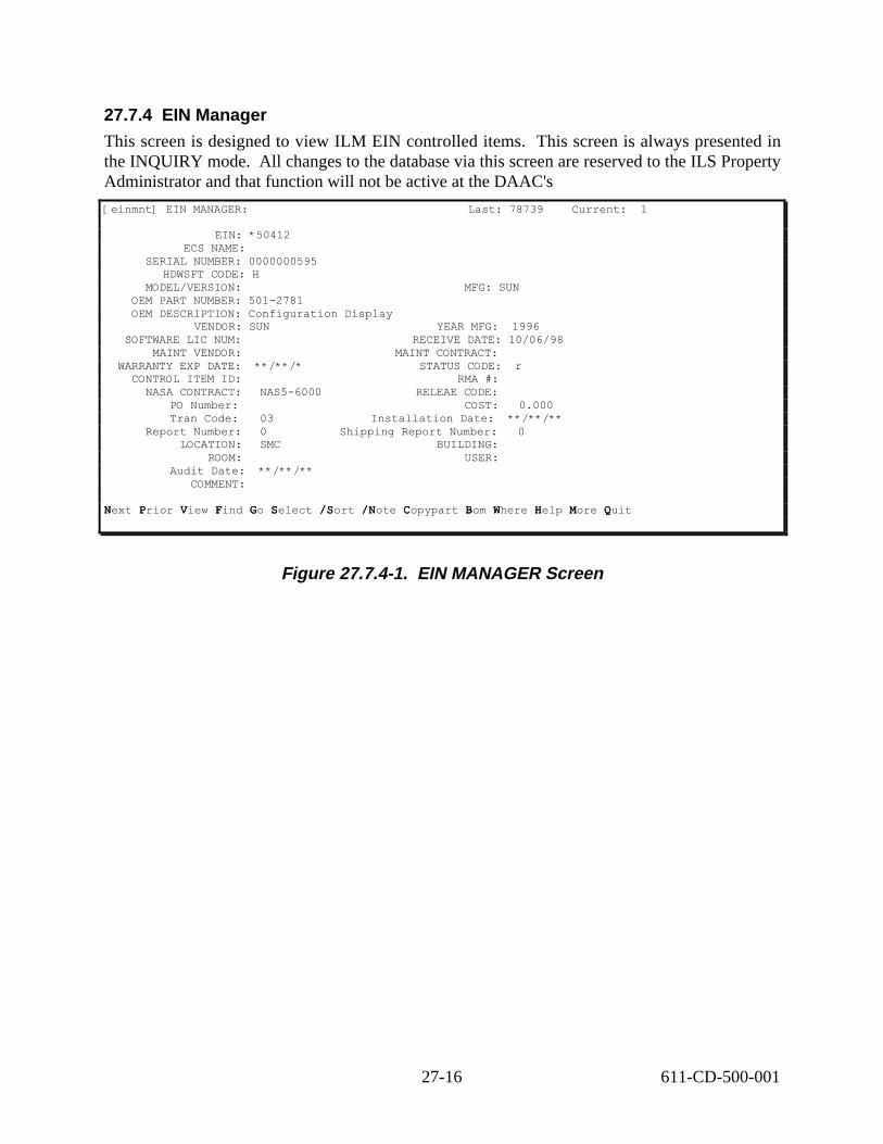
NNN PP VV FF GG SS //SSS //NNN CC BB WW HH MM QQ
27.7.4 EIN Manager
This screen is designed to view ILM EIN controlled items. This screen is always presented in the INQUIRY mode. All changes to the database via this screen are reserved to the ILS Property Administrator and that function will not be active at the DAAC's
[einmnt] EIN MANAGER: Last: 78739 Current: 1
EIN: *50412 ECS NAME:
SERIAL NUMBER: 0000000595 HDWSFT CODE: H
MODEL/VERSION: MFG: SUN OEM PART NUMBER: 501-2781 OEM DESCRIPTION: Configuration Display
VENDOR: SUN YEAR MFG: 1996 SOFTWARE LIC NUM: RECEIVE DATE: 10/06/98
MAINT VENDOR: MAINT CONTRACT: WARRANTY EXP DATE: **/**/* STATUS CODE: r
CONTROL ITEM ID: RMA #: NASA CONTRACT: NAS5-6000 RELEAE CODE:
PO Number: COST: 0.000 Tran Code: 03 Installation Date: **/**/**
Report Number: 0 Shipping Report Number: 0 LOCATION: SMC BUILDING:
ROOM: USER: Audit Date: **/**/**
COMMENT:
Next P View F Go S /Sort / Copypart B Where H More QPrior V Find G Select / /Note C Bom W Help M Quit
Figure 27.7.4-1. EIN MANAGER Screen
27-16 611-CD-500-001

Table 27.7.4-1. EIN Manager Field Description (1 of 2) Field Name Data
Type Size Description
EIN String 14 Database changes are reserved to the ILS PA
ECS NAME String 23 This field provides the name the item will be known by. Database changes are reserved to the ILS PA
SERIAL NUMBER
String 30 This field is the serial number of the product. If the item does not contain a serial number of it’s own; the system will assign an internal number prefixed with the Site abbreviation and contain a sequentially assigned number. Pressing RETURN at the field prompt automatically performs this internal assignment. Database changes are reserved to the ILS PA
HDWSFT CODE String 10 This field provides a code designating the type of item. Database changes are reserved to the ILS PA
MODEL/VERSIO N
String 24 This field is the actual Model and or Version of the item. If the user had chosen a known OEM Part, this field will be written with the information from this file. Database changes are reserved to the ILS PA
MFG String 6 This is the code of the manufacturer.
OEM PART NUMBER
String 34 This field is the Manufacturer or Vendor’s part number. Database changes are reserved to the ILS PA
OEM DESCRIPTION
String 30 This field reflects the description of the OEM PART NUMBER entered in the field above, Database changes are reserved to the ILS PA
VENDOR String 6 This field is the Vendor code whom the item was purchased from.
SOFTWARE LIC NUM
String 10 This field is the license number for a software type license item.
MAINT VENDOR String 6 This field is the code for the vendor who is the maintenance vendor.
WARRANTY EXP DATE
Date 8 This field is the end date for the warranty period. This field default to 365 days from the date of entry.
CONTROL ITEM ID
String 20 This field provides the ability for the user to point to an equivalent item contained within the BASELINE MANAGEMENT system. ILM will enter the BLM Control Item based on the OEM Part Number. Database changes are reserved to the ILS PA
NASA CONTRACT
String 11 This field is used to designate the Contract number used for this item. This information is automatically assigned.
PO Number String 10 Database changes are reserved to the ILS PA.
Tran Code Number 3 This field designates the transaction code. The value will always be set to ‘03’
Report Number Number 4 This field is the installation report number assigned by the system when an installation had occurred.
27-17 611-CD-500-001

Table 27.7.4-2. EIN Manager Field Description (2 of 2) Field Name Data
Type Size Description
LOCATION String 8 This field is used to designate the actual location or site of where the item is.
BUILDING String 6 This field is used to designate the building number within the site where the item is. Database changes are reserved to the ILS PA.
ROOM String 6 This field is used to enter the actual room number of where the item is or will be shipped to. Database changes are reserved to the ILS PA
YEAR MFG String 4 This field is used to enter the actual 4-digit year the item was manufactured. This field defaults to the current year.
RECEIVE DATE String 8 Date item was received from vendor
MAINT CONTRACT String 15 This field is used to enter the Maintenance Contract number for maintenance on this particular item.
STATUS CODE String 1 This field designates the status of the item and is controlled by transactions within the system. The following codes are included : R - Received; S – Shipped; I - Installed; X - Archived;
RMA# String 6 Reliability Maintainability Availability number.
RELEASE CODE String 10 This field is the actual release code for the item.
COST Floatin g
9.2 This field is the purchase cost of the item.
Installation Date Date 8 This date reflects the actual date this item was installed. Database changes are reserved to the ILS PA
Shipping Report Number
Numb er
2 This field is the report number assigned to this item when the item was shipped.
USER String 8 The user code of the person who has the item.
COMMENT String 60 This field is a user comment field.
NOTE String 60 This field is used to enter a 60 character note attached to this item.
Table 27.7.4-3. Procedure to Inquiry for EIN STEP ACTION OCCURRENCE
STEP 1 From the Main Menu A. Select ILM Main Menu – press ‘enter’ B. Select EIN Menu – press ‘enter’ C. Select EIN Manager – press ‘enter’
This will give you the EIN Manager screen.
STEP 2 Look for the EIN of interest A. Press ‘f’ to do a Find or ‘s’ to do a Select B. Enter the EIN number C. Press ‘F5’ to start the search
The EIN information will come up.
STEP 3 Press ‘F3’ to exit the EIN Manager screen when complete.
Remember to press <ENTER> after each field.
27-18 611-CD-500-001

----------------
27.8 ILM Report Menu ILM Report Menu provides access to display and report controlled items in the database. This section of ILM is mainly used for reporting purposes. When the user authorization is more limited, this menu offers fewer options. In this and the following sections, the content of the menus and the screen layouts cover the complete functionality although all of the functions will not be available to every user. The ILM Report menu lets the users navigate to the following screens:
ECS Management System Ilmrepm ILM Report Menu 11/11/98 12:56
1. EIN Structure Reports 2. Install/Receipt Reports 3. Installation Summary Reports
Please enter selection (1-3 or name):
F1-help F3-prior menu F5-select F8-exit
Figure 27.8-1. Report Menu
Table 27.8-1. ILM Reports Menu options Menu item Function Section
EIN Structure reports
This screen retrieves and prints all designated parents and components in a multi-level bill report.
2.2.1
Install/Receipt Report
This screen allows the user to print a report of a parent EIN configuration and send the hard copy to the receiving organization for sign off.
2.2.2
Installation Summary Report
This screen allows the user to print a summary report by range
2.2.3
This menu allows the user to print a series of hard or soft copy reports of various information contained within the system.
27.8.1 EIN Structure Reports
This screen is designed to retrieve and print all designated parents and components in a multilevel bill report.
27-19 611-CD-500-001

[einstrep] EIN STRUCTURE REPORTS: Last: 5 Current: 1
EIN OR RANGE: 00000357
NUMBER OF LEVELS TO EXPLODE: 99
EXPLOSION QUANTITY: 1
DATE OF BILL: 01/01/01 [Enter 1/1/1 for current date]
TYPE OF SORT (SN): [null = part S=sort string N=sort #]
NOTE 1: This is a test! NOTE 2:
NUMBER OF COPIES
EIN MULTI-LEVEL REPORT: 1
Next Prior Find Go Select /Sort /Note Execute Help More Quit /Zoom
Figure 27.8.1-1. EIN Structure Reports Screen
Table 27.8.1-1. EIN Structure Reports Field Descriptions
Field Name Data Type Size Description
EIN or RANGE String 14 Field can accept two 14 character strings. E.g. 00001234- 00003456 for a range
NUMBER OF LEVELS TO EXPLODE
Number 2 Enter number of levels to display for a particular parent structure.
EXPLOSION QUANTITY
Number 2 Enter number of level to be displayed for parent in structure
DATE OF BILL Date 8 Date item was billed
TYPE OF SORT String 1 Null = part, S=Sort string N = Sort number
NOTE 1 String 60 This field is used to enter a 60-character note attached to this report.
NOTE 2 String 60 This field is used to enter a 2nd 60-character note attached to this report.
EIN MULTI- LEVEL REPORT
Number 2 Enter the number of copies of this report to generate.
27-20 611-CD-500-001

Table 27.8.1-2. Procedures to generate EIN structure reports STEP ACTION OCCURRENCE
STEP 1 From the Main Menu A. Select ILM Main Menu – press ‘enter’ B. Select ILM Report Menu – press ‘enter’ C. Select EIN Structure Reports – press ‘enter’
This will give you the EIN Structure Reports screen.
STEP 2 Press ‘/a’ to go into add mode.
STEP 3 Fill in the necessary information A. Enter EIN number you want to report on. You may
zoom to the EIN data file to pick the EIN you want. To do this, press (‘/z’, ‘t’, ‘F3’).
B. Enter Number of levels to explode, explosion quantity, and Date of Bill.
C. Enter the type of sort. -null = part -‘s’ = sort string -‘n’ =sort #
D. Enter any note to appeal on the report header E. Enter the EIN multi-level report
STEP 4 Press 'F3' to exit adds mode. This will bring you back to the EIN Structure screen.
STEP 5 Press ‘e’ to execute the transaction. A Report Destination prompt will come up that allow you to select the location where you want the report to go.
STEP 6 Press ‘F3’ if you do NOT want to print the report. If you want to print it on the screen, choose option 1 and press ‘enter’.
A formatted report will come up. You have several options: Next/Previous/Right/Quit/Hardcopy?
STEP 7 A. Make your selection -Press ‘n’ for Next -Press ‘p’ for Previous -Press ‘r’ for Right -Press ‘q’ for Quit or -Press ‘h’ to print a hardcopy of the report
B. After finished making your selection, press ‘q’ to exit the report screen. A message will come up specifying the number of reports generated, press ‘enter’.
C. Another message will prompt up “Another?” -Press ‘y’ if you want to generate more reports. This will take you back to the EIN Structure Reports screen, or -Press ‘n’ this will take you back to the ILM Report Menu.
Remember to press <ENTER> after each field.
27-21 611-CD-500-001

27.9 Install/Receipt Report This screen is designed to allow the user to print a report of a parent EIN configuration and send the hard copy to the receiving organization for sign off.
[insrep] INSTALL/RECEIPT REPORT:
PARENT EIN: Ecs Name:
OEM Description: Serial Number: Model/Version:
Mfr/dev: OEM Part Number:
Status Code: Control Item ID:
Old Location: Old Building:
Old Room: Old User:
ENTER NUMBER OF COPIES
INSTALL/RECEIPT REPORT:
ADD: F1-help F2-clear F3-exit F4-mode F6-default /Zoom Typeover mode
Figure 27.9-1. Install/Receipt Report Screen
Table 27.9-1. Install/Receipt Report Field DescriptionsField Name Data Type Size Description
PARENT EIN String 14 This field is the Parent EIN for the installation/structure.
Ecs Name through Old User
MULTI- FIELD
These fields reflect according to the Parent EIN you entered.
INSTALL/RECEIPT REPORT
Number 2 Enter number of copies of this report to generate.
27-22 611-CD-500-001

Table 27.9-2. Procedures to generate Install/Receipt reports STEP ACTION OCCURRENCE/NOTE
STEP 1 From the Main Menu A. Select ILM Main Menu – press ‘enter’ B. Select ILM Report Menu - press ‘enter’ C. Select Install/Receipt Reports - press ‘enter’
This will give you the Install/Receipt Reports screen.
STEP 2 Press ‘/a’ to go into add mode.
STEP 3 Fill in the necessary information A. Enter Parent EIN or you may zoom to the EIN
data file to select the EIN of interest. To do this, press (‘/z’, ‘t’, ‘F3”).
B. ECS Name through Old User – these fields are reflected from the Parent EIN you entered above.
C. Enter number of copies for the Install/Receipt Report.
STEP 4 Press ‘F3’ to exit add mode. This will bring you back to the Install/Receipt Report screen.
STEP 5 Press ‘e’ to execute the transaction. A Report Destination prompt will come up that allow you to select the location where you want the report to go.
STEP 6 Press ‘F3’ if you do NOT want to print the report. If you want to print it on the screen, choose option 1 and press ‘enter’.
A formatted report will come up. You have several options: Next/Previous/Right/Quit/Hardcopy ?
STEP 7 A. Make your selection -Press ‘n’ for Next -Press ‘p’ for Previous -Press ‘r’ for Right -Press ‘q’ for Quit or -Press ‘h’ to print a hardcopy of the report
B. After finished making your selection, press ‘q’ to exit the report screen. A message will come up specifying the number of reports generated, press ‘enter’.
C. Another message will prompt up “Another?” -Press ‘y’ if you want to generate more reports. This will take you back to the Install/Receipt Reports screen, or -Press ‘n’, this will take you back to the ILM Report Menu.
Remember to press <ENTER> after each field.
27-23 611-CD-500-001

27.10Installation Summary Reports
This screen is designed to retrieve and print all receipts that have occurred for the designated PO, Vendor, or Date.
[installr] INSTALLATION SUMMARY REPORTS: Last: 4 Current: 1
INSTALLATION DATE or Range: 10/10/98-11/10/98
NOTE 1: Test 1 NOTE 2: Testing
ENTER NUMBER OF COPIES
INSTALLATIN REPORTS: 1
Next Prior Find Go Select /Sort /Note Write Execute Help More Quit
Figure 27.10-1. Installation Summary Reports Screen
Table 27.10-1. Installation Summary Reports Field Descriptions Field Name Data Type Size Description
INSTALLATION DATE or RANGE
MULTI- FIELD
Enter installation date or range of dates to report on as one or two fields.
NOTE 1 String 60 This field is used to enter a 60-character note attached to this item.
NOTE 2 String 60 This field is used to enter a 2nd 60 character note attached to this item.
INSTALLATION REPORTS
Number 4 This field is the installation report number assigned by the system when an installation had occurred and as reflected from the EIN Record for the Parent EIN.
27-24 611-CD-500-001

Table 27.10.-2. Procedures to generate installation summary reports STEP ACTION OCCURRENCE
STEP 1 From the Main Menu A. Select ILM Main Menu – press ‘enter’ B. Select ILM Report Menu - press ‘enter’ C. Select Installation Summary Reports - press
‘enter’
This will give you the Installation Summary Reports screen.
STEP 2 Press ‘/a’ to go into add mode.
STEP 3 A. Enter the Installation date or range (i.e. 10/10/98-11/10/98).
B. Specify number of copies.
STEP 4 Press ‘F3’ to exit the add mode. This will bring you back to the Installation Summary Reports screen.
STEP 5 Press ‘e’ to execute the transaction. A Report Destination prompt will come up that allow you to select the location where you want the report to go.
STEP 6 Press ‘F3’ if you do NOT want to print the report. If you want to print it on the screen, choose option 1 and press ‘enter’.
A formatted report will come up. You have several options: Next/Previous/Right/Quit/Hardcopy?
STEP 7 A. Make your selection -Press ‘n’ for Next -Press ‘p’ for Previous -Press ‘r’ for Right -Press ‘q’ for Quit or -Press ‘h’ to print a hardcopy of the report
B. After finished making your selection, press ‘q’ to exit the report screen. A message will come up specifying the number of reports generated, press ‘enter’.
C. Another message will prompt up “Another?” -Press ‘y’ if you want to generate more reports. This will take you back to the Installation Summary Reports screen. -Press ‘n’, this will take you back to the ILM Report Menu.
Remember to press <ENTER> after each field.
27.11 Maintenance Menu The ILM Maintenance Menu is used to maintain the ILM database of maintenance oriented data, generate and track Work Orders for maintenance actions, and schedule preventative maintenance for appropriate items. (Please note) The arrangement of this screen will appear different in ILM but the content within the selections will remain the same.
27-25 611-CD-500-001

----------------
ECS Management System maintm Maintenance Menu 11/11/98 12:56
1. Work Order Entry 2. Work Order Modification 3. Prevenative Maintenance Items 4. Generate PM order
5. Maintenance Work Order Reports 6. Maintenance Work Order Status 7. Maintenance Codes 8. Maintenance Contacts 9. Authorized Employees
Please enter selection (1-10 or name):
F1-help F3-prior menu F5-select F8-exit
Figure 27.11-1. Maintenance Menu Screen
Table 27.11-1. Maintenance Menu options Menu item Function Section
Work Order Entry Provides the ability enter Work Orders for repairs 3.1.1
Work Order Modification Provides the ability to modify Work Orders for repairs 3.1.2
Preventative Maintenance Items
Provides the ability to designate which items in the EIN file should experience preventative maintenance.
3.1.3
Generate PM Orders Provides the ability to generate Work Orders for an item needing PM
3.1.4
Maintenance Work Order Reports
Provides Work Order Reports for work done on selected machines.
3.1.5
Work Order Status Reports
Provides status reports on selected Work Orders. 3.1.6
Maintenance Codes Provides the failure codes and descriptions for use with repairs and replacements.
3.1.7
Maintenance Contracts Provides the maintenance contract numbers for repair contracts with vendors and suppliers.
3.1.8
Authorized Employees Provides the ability enter and maintain employee codes for employees who have been permitted access to the vendor for repair notification.
3.1.9
27.11.1 Work Order Entry Screens This screen provides the ability to enter Work Orders for repairs. The operator will complete the required fields and upon exit of the screen, the system copies the EIN children to the parent. This screen is always presented in ADD mode.
27-26 611-CD-500-001

[wordent] WORK ORDER ENTRY:
WORK ORDER: PARENT EIN: Serial Number:
Name: OEM Part:OEM Desc:
Mod/Ver:Building:
TROUBLE TICKET #:NOTIFICATION DATE:
PRIORITY:FAILURE DATE:
MFG/DEV:MAINT VENDOR:
VENDOR CALL DATE:VENDOR CONTACT NAME:
VENDOR REFERENCE:TEXT:
CODE: NOTE:
RETURN for next
Location: Room:
NOTIFICATION TIME: SUBMITTER:
FAILURE TIME: VENDOR:
TIME:
ADD: F1-help F2-clear F3-exit F4-mode F6-default Typeover mode
Figure 27.11.1-1. Work Order Entry Screen
27-27 611-CD-500-001

Table 27.11.1-1. Work Order Entry Field Descriptions (1 of 2) Field Name Data
Type Size Description
WORK ORDER String 10 This is the actual Work Order number. The operator should always press RETURN to obtain the next number sequentially assigned by the system.
PARENT EIN String 14 This field is the Parent EIN of the failed component.
SERIAL NUMBER through ROOM
MULTI-FIELD
These fields are all reflected from the EIN file for the Parent as entered.
TROUBLE TICKET #
String 15 Enter the applicable trouble ticket number here
OEM PART# String This field is the OEM part number reflected from the EIN record of the child.
OEM DESC String This field reflects the description of the OEM PART NUMBER entered in the field above, but provides the ability for the user to modify it in the EIN file.
MOD/VER String This field is used to enter the actual Model or Version of the item. If the user had chosen a known OEM Part, this field will be written with the information from this file.
BUILDING String These fields are all reflected from the EIN file for the Parent as entered.
LOCATION String These fields are all reflected from the EIN file for the Parent as entered.
ROOM String These fields are all reflected from the EIN file for the Parent as entered.
NOTIFICATION DATE
Date 8 Notification Date
NOTIFICATION TIME
Time 5 Notification Time
PRIORITY String 1 Enter ‘H’ for high, ‘M’ for medium, and ‘L’ for low.
SUBMITTER String 10 Enter the employee code for the person who submitted the problem and caused the work order to be opened.
FAILURE DATE Date 8 Enter actual failure date.
FAILURE TIME String 5 Enter actual failure time.
MFR/DEV String 6 This field is used to enter the Manufacturer or Developer ID.
VENDOR String 6 This field is used to enter the Vendor code whom the item was purchased from.
MAINT VENDOR
String 6 This field is used to enter the code for the vendor who is the maintenance vendor.
VENDOR CALL DATE
Date 8 Date the vendor was called and informed of the problem.
VENDOR CALL TIME
Time 5 Time the vendor was called and informed of the problem.
27-28 611-CD-500-001

Table 27.11.1-1. Work Order Entry Field Descriptions (2 of 2) Field Name Data
Type Size Description
VENDOR CONTACT NAME
String 30 Vendor point of contact
VENDOR REFERENCE
String 20 User has option to enter any information in reference to the vendor
CODE String 2 This code is reserved for the ILS PA
NOTE String 60 This field is used to enter a 60 characters note attached to this item.
TEXT String 8 Press /Z at this prompt to obtain a free form text window. The operator should enter the failure / repair details in this window. When complete, press F3 to exit the text window.
27.11.2 Item Page for Work Order Entry Screens
The Work Order Entry Item option provides a list of the components of the Parent EIN specified in the Work Order. The Work Order Entry Item option will display the
following screen.
[wordent] WORK ORDER ENTRY: Last: 1 Current: 1
Work Order: 00000000037 Parent Ein: 00001234Serial Number: 01C15104279Name: KIDNAPEDOem Part: P-TERM2Oem Desc: TerminalMod/ver: Location:
Last: 2 Current: 1
COMPONENT EIN: C0012834 OEM Part: X756
OEM Desc: 2.1 GH HD œ Fast Wide Mod/Ver:
SERIAL NUMBER: 9530625228 FAILURE CODE: MAINT CODE:
MAINT CONTRACT: CCW3045 PO NUMBER: CCW0002396 RECEIVE DATE: 09/23/95 MANUFACTURED DATE:
VENDOR: SUN WARRANTY DATE: 12/31/98
REPLACE (R) or NEW (N): REPLACE OR ADD DATE: **/**/**
Next Prior View Find Go Select /Sort /Note Copy-bill Help More Quit /Zoom
Figure 27.11.2-1. Item Page for Work Order Entry Screen
27-29 611-CD-500-001

Table 27.11.2-1. Item Page for Work Order Entry Field Descriptions Field Name Data
Type Size Description
WORK ORDER String 10 This is the actual Work Order number. The operator should always press RETURN to obtain the next number sequentially assigned by the system.
PARENT EIN String 14 This field is the Parent EIN of the failed component.
SERIAL NUMBER through LOCATION
MULTI-FIELD
These fields are all reflected from the EIN file for the Parent as entered.
COMPONENT EIN String 35 This field is the component EIN number of the Parent EIN.
OEM PART String 34 This field is the OEM part number reflected from the EIN record of the child.
OEM DESC (WO) String 40 This field reflects the description of the OEM PART NUMBER entered in the field above, but provides the ability for the user to modify it in the EIN file.
MOD/VER String 24 This field is used to enter the actual Model and or Version of the item. If the user had chosen a known OEM Part, this field will be written with the information from this file.
SERIAL NUMBER String 30 This field is for the entry of the serial number of the product being entered.
FAILURE CODE String 2 Code identifying the failure
MAINT CODE String 3 The user will enter any desired code in this field.
MAINT CONTRACT String 15 This field is used to enter the Maintenance Contract number for maintenance on this particular item.
PO NUMBER String 10 This will be system populated when the item has been tagged.
RECEIVED DATE Date 8 The date the item was received.
MANUFACTURED DATE
Date 8 Date Manufactured
VENDOR String 6 This field is used to enter the Vendor code whom the item was purchased from.
WARRANTY DATE (WO)
Date 8 This field is the end date for the warranty period.
REPLACE (R) or NEW (N)
String 1 Enter an ‘R’ in this field for the Child EIN that had been replaced in the machine. When entering a new item, be sure to place an ‘N’ in this field to designate the record as being new.
REPLACE OR ADD DATE
String 8 Date add or replace occurred.
RECORD EVENTS String 1 Flag of T for Text indicates other events to be recorded.
27-30 611-CD-500-001

Table 27.11.2-2. Procedures to enter new work order(1 of 2) STEP ACTION OCCURRENCE/NOTE
STEP 1 From the Main Menu A. Select ILM Main Menu – press ‘enter’ B. Select Maintenance Menu – press ‘enter’ C. Select Work Order Entry – press ‘enter’
This will give you the Work Order Entry screen.
STEP 2 Fill in the necessary information A. Press ‘enter’ to get the next work order
number. B. Enter Parent EIN number or press ‘/z’, choose
the Parent EIN from the list by pressing ‘t’, then press ‘F3’or "Q' quit
C. Serial Number through Room number – these fields reflected from the Parent EIN you entered above.
D. Enter the applicable trouble ticket number E. Enter the date and time the problem was
notified F. Enter problem priority, 1 being the highest G. Enter the employee code for the person who
submitted the problem – you may press ‘/z’, choose the employee code from the list by pressing ‘t’, then press ‘F3’ or 'q' to quit
H. Enter the actual failure date and time I. Enter the Manufacturer ID or press ‘/z’, choose
the ID from the list by pressing ‘t’, then press ‘F3’ or 'q' to quit.
J. Enter vendor code - press ‘/z’, choose the Vendor code from the list by pressing ‘t’, then press ‘F3’ or 'q' to quit
K. Enter maintenance vendor - press ‘/z’, choose the vendor code from the list by pressing ‘t’, then press ‘F3’ or 'q' to quit
L. Enter date and time vendor was called and informed of the problem
M. Enter vendor contact name N. Enter any reference information to the vendor O. At the Text field - Press ‘/z’ to enter the
failure/repair details and press ‘F3’ when finished.
P. You may enter any farther note in the note field.
STEP 3 Press ‘F3’ to go to the next step You will see the same screen as the previous one with an added bottom line command of ‘I’
27-31 611-CD-500-001

Table 27.11.2-2. Procedures to enter new work order(2 of 2) STEP ACTION OCCURRENCE/NOTE
STEP 4 If you know the actual failed part Press ‘I’ to bring you to the items page where the different components of the parent machine are listed
If you are not sure of the failed part, skip to STEP 7 and choose ‘Y’ to copy in EIN children when exiting.
STEP 5 A. Look for the particular component that failed by pressing ‘n’ for next or ‘p’ for previous
B. Press ‘/m’ to specify the failed component C. Fill in the failure code for the failed component
– press ‘/z’, choose the failure code from the list by pressing ‘t’, then press ‘F3’
D. DO NOT place anything in the line that gives you an option of ‘r’ or ‘n’. If this is filled out, it indicates that the Work Order is closed and therefore may not be modified anymore after leaving the screen.
STEP 6 Press ‘F3’ until ILM takes you out of the Work Order Entry screen
STEP 7 Press 'F3" again and you will be questioned "copy in EIN children say 'y" and "n" to exit. Choose ‘y’ unless you know the failed components and have selected them on the items screen.
This will copy all the children with the Maintenance Work Order. This function is used when not sure which part has failed.
Remember to press <ENTER> after each field.
27.12 Work Order Modification Screens This screen provides the ability to modify Work Orders for repairs. This screen should be used when the repair has been completed and all appropriate information about the repair is known. The operator will enter or modify information in the fields as appropriate then invoke the item page to view the EIN children for the parent. The operator also has the ability with this screen to enter delay times and chargeable times. Press the ‘R’ key to move to the next screen to input delay times and chargeable times.
27-32 611-CD-500-001
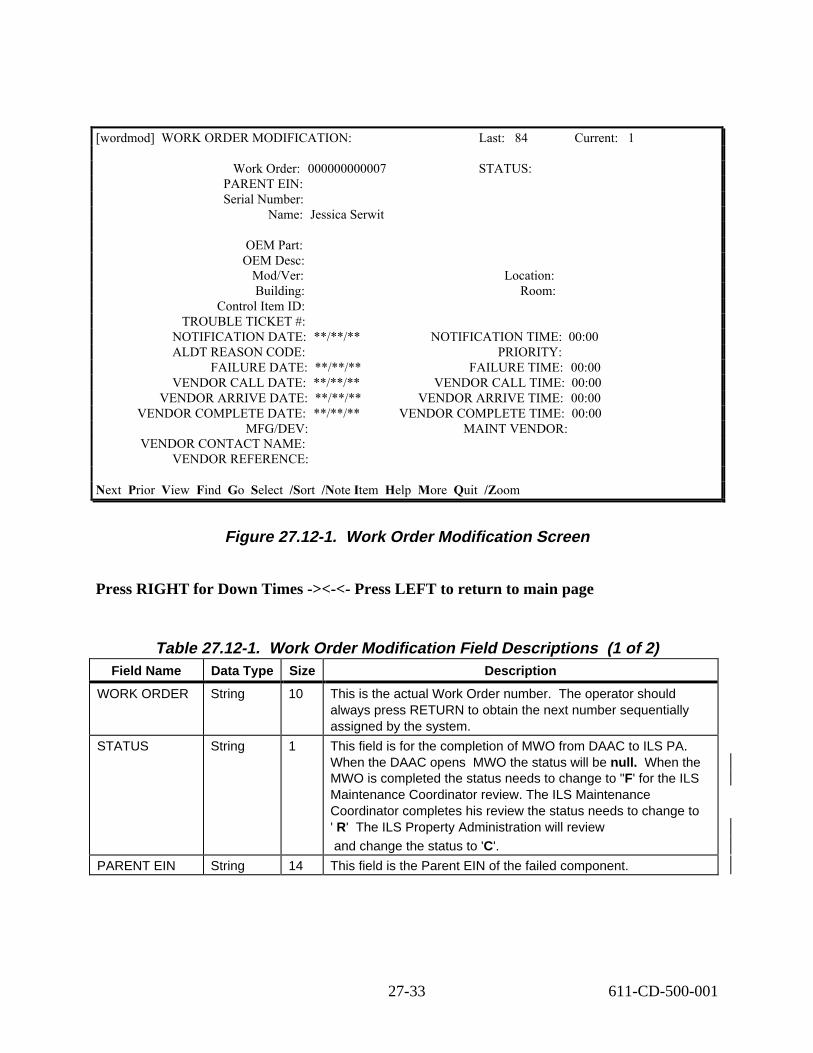
[wordmod] WORK ORDER MODIFICATION:
Work Order: 000000000007 PARENT EIN: Serial Number:
Name: Jessica Serwit
OEM Part: OEM Desc:
Mod/Ver: Building:
Control Item ID: TROUBLE TICKET #:
NOTIFICATION DATE: **/**/** ALDT REASON CODE:
FAILURE DATE: **/**/** VENDOR CALL DATE: **/**/**
VENDOR ARRIVE DATE: **/**/** VENDOR COMPLETE DATE: **/**/**
MFG/DEV: VENDOR CONTACT NAME:
VENDOR REFERENCE:
Last: 84 Current: 1
STATUS:
Location: Room:
NOTIFICATION TIME: 00:00 PRIORITY:
FAILURE TIME: 00:00VENDOR CALL TIME: 00:00
VENDOR ARRIVE TIME: 00:00VENDOR COMPLETE TIME: 00:00
MAINT VENDOR:
Quit /ZoomNext Prior View Find Go Select /Sort /Note Item Help More
Figure 27.12-1. Work Order Modification Screen
Press RIGHT for Down Times -><-<- Press LEFT to return to main page
Table 27.12-1. Work Order Modification Field Descriptions (1 of 2) Field Name Data Type Size Description
WORK ORDER String 10 This is the actual Work Order number. The operator should always press RETURN to obtain the next number sequentially assigned by the system.
STATUS String 1 This field is for the completion of MWO from DAAC to ILS PA. When the DAAC opens MWO the status will be null. When the MWO is completed the status needs to change to "F' for the ILS Maintenance Coordinator review. The ILS Maintenance Coordinator completes his review the status needs to change to ' R' The ILS Property Administration will review and change the status to 'C'.
PARENT EIN String 14 This field is the Parent EIN of the failed component.
27-33 611-CD-500-001

Table 27.12-1. Work Order Modification Field Descriptions (2 of 2) Field Name Data Type Size Description
Serial Number through Control Item Id
MULTI-FIELD
These fields are all reflected from the EIN file for the Parent as entered.
TROUBLE TICKET #
String 15 Enter the applicable trouble ticket number here
NOTIFICATION DATE and TIME
MULTI-FIELD
These fields are initialized with the current date and time and can be modified.
ALDT REASON CODE
String 10 Enter the reason code for the ALDT.
PRIORITY String 1 Enter ‘H’ for high, ‘M’ for medium, and ‘L’ for low.
FAILURE DATE and TIME
MULTI-FIELD
Enter actual failure date and time.
ALDT Floating 9.1 This field is used to enter the known (actual) ALDT time in hours.
VENDOR CALL DATE and TIME
MULTI-FIELD
Enter the date and time the vendor actually arrived to perform the repairs.
VENDOR ARRIVE DATE and TIME
MULTI-FIELD
Enter the date and time the vendor actually arrived to perform the repairs.
VENDOR COMPLETE DATE and TIME
MULTI-FIELD
Enter the actual date and time the vendor completed the repairs.
MFR/DEV String 6 This field is used to enter the Manufacturer or Developer ID.
MAINT VENDOR
String 6 This field is used to enter the code for the vendor who is the maintenance vendor.
VENDOR CONTACT NAME
String 30 Vendor point of contact
VENDOR REFERENCE
String 20 Reference number vendor gives to refer to the case reported.
EVENTS String 30 Enter a detail description of the problem and the solution.
NOTE String 60 This field is used to enter a 60 character note attached to this item.
27.13 Delay Times Page for Work Order Modification Screens This screen provides the ability to maintain delay date and times to be used for downtime calculations.
27-34 611-CD-500-001

[wordmod] WORK ORDER MODIFICATION: Last:______ Current:______
<-<- LEFT to return to main page _ RIGHT for Charge Times ->-> START DATE: __/__/__ END DATE: __/__/__ START TIME: ___:___ END TIME: ___:___
REASON:____________
START DATE: __/__/__ END DATE: __/__/__ START TIME: ___:
___ END TIME: ___:___ REASON:____________
START DATE: __/__/__ END DATE: __/__/__ START TIME: ___:___ END TIME: ___:___
REASON:____________
START DATE: __/__/__ END DATE: __/__/__ START TIME: ___:___ END TIME: ___:___
REASON:____________
Figure 27.13-1. Delay Times Page for Work Order Modification
Table 27.13-1. Delay Time Page for Work Order Modification Field Descriptions Field Name Data Type Size Description
START DATE and END DATE
MULTI-FIELD
These fields are used to enter the beginning and ending dates for known delay times in the repair of a system.
START TIME and END TIME
MULTI-FIELD
These fields are used to enter the beginning and ending times associated with the dates above for known delay times in the repair of a system.
REASON String 4 Enter the appropriate reason code for the delay entered.
27-35 611-CD-500-001
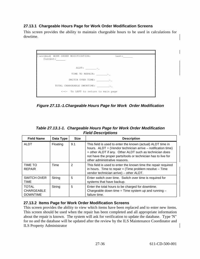
27.13.1 Chargeable Hours Page for Work Order Modification Screens
This screen provides the ability to maintain chargeable hours to be used in calculations for dowtime.
[wordmod] WORK ORDER MODIFICATION: Last:______ Current:______
ALDT: _______._
TIME TO REPAIR: _______._
SWITCH OVER TIME: ________._
TOTAL CHARGEABLE DWONTIME: ________._
<-<- To LEFT to return to main page
Figure 27.13.-1.Chargeable Hours Page for Work Order Modification
Table 27.13.1-1. Chargeable Hours Page for Work Order Modification Field Descriptions
Field Name Data Type Size Description
ALDT Floating 9.1 This field is used to enter the known (actual) ALDT time in hours. ALDT = (Vendor technician arrive – notification time) + other ALDT if any. Other ALDT such as technician does not have the proper parts/tools or technician has to live for other administrative reasons.
TIME TO REPAIR
Time 2 This field is used to enter the known time the repair required in hours. Time to repair = (Time problem resolve – Time vendor technician arrive) – other ALDT.
SWITCH OVER TIME
String 5 Enter switch over time. Switch over time is required for systems that have backup.
TOTAL CHARGEABLE DOWNTIME
String 5 Enter the total hours to be charged for downtime. Chargeable down time = Time system up and running – failure time.
27.13.2 Items Page for Work Order Modification Screens This screen provides the ability to view which items have been replaced and to enter new items. This screen should be used when the repair has been completed and all appropriate information about the repair is known. The system will ask for verification to update the database. Type 'N" for no and the database will be updated after the review by the ILS Maintenance Coordinator and ILS Property Administrator
27-36 611-CD-500-001

Last: ____ Current: _____
COMPONENT EIN: ____________________ OEM Part: __________________________________ OEM Desc: ________________________________________ Mod/Ver: ________________________
SERIAL NUMBER: ______________________________ FAILURE CODE: __________ MAINT CODE: ___
MAINT CONTRACT: _______________ PO NUMBER: __________ RECEIVE DATE: __/__/__ MANUFACTURED DATE: ____
VENDOR: ______ WARRANTY DATE: __/__/__
PLACE (R) or NEW (N): _ REPLACE OR ADD DATE: __/__/__
RECORD EVENTS: _ Next prior View Find Go Select /Sort /Note Copy-bill Help More Quit
Figure 27.13.2-1. Items Page for Work Order Modification
Table 27.13.2-1. Items Page for Work Order Modification Field DescriptionsField Name Data Type Size Description
COMPONENT EIN
String 35 This field is the component EIN number of the Parent EIN.
EOM PART through WARRANTY DATE
MULTI-FIELD
These fields are all copied from the child EIN record and may be modified in this screen as required.
REPLACE (R) or NEW (N)
String 1 Enter an ‘R’ in this field for the Child EIN that had been replaced in the machine. When entering a new item, be sure to place an ‘N’ in this field to designate the record as being new.
TEXT String 8 Press /Z at this prompt to obtain a free form text window. The operator should enter the failure / repair details in this window. When complete, press F3 to exit the text window.
27-37 611-CD-500-001

Table 27.13.2-2. Procedures to Modify Work Order (1 of 2) STEP ACTION OCCURRENCE
STEP 1 From the Main Menu A. Select ILM Main Menu – press ‘enter’ B. Select Maintenance Menu – press ‘enter’ C. Select Work Order Modification – press ‘enter’
This will give you the Work Order Modification screen.
STEP 2 -Press ‘f’ to find a particular work order, type the work order number and then press ‘F5’ , or -You may also look for a particular work order by pressing ‘v’ to bring you to the list mode, find the particular record you want by placing the cursor on the line of the desired record and then pressing ‘v’ again to bring you back to the individual record mode.
This will pull up the Work Order record.
STEP 3 Press ‘/m’ to go into modify mode.
STEP 4 Fill in the necessary information A. Enter vendor arrive date and time – when the
vendor technician arrived on site B. Enter vendor complete date and time – when the
equipment is up and running again.
STEP 5 Press ‘F3’ to go to the next step
STEP 6 A. Press ‘r’ to go to the right of this screen. B. Press ‘/m’ to go into modify mode C. Fill in the delay date, time and the reason for delay.
This will bring you to the Delay Times Page for Work Order Modification screen.
STEP 7 Press ‘F3’ to go to the next step
27-38 611-CD-500-001

Table 27.13.2-2. Procedures to Modify Work Order (2 of 2) STEP ACTION OCCURRENCE
STEP 8 A. Press ‘r’ until ILM takes you to the Chargeable Hours page for Work Order Modification screen.
B. Press ‘/m’ to go into modify mode C. Enter the Administrative Logistic Delay Time
(ALDT). ALDT = (Vendor technician arrive – notification time) + other ALDT if any. Other ALDT such as technician does not have the proper parts/tools or technician has to live for other administrative reasons.
D. Enter the total time to repair. Time to repair = (Time problem resolve – Time vendor technician arrive) – other ALDT.
E. Enter Switch over time, if any F. Enter total chargeable downtime. Chargeable down
time = Time system up and running – failure time.
STEP 9 Press ‘F3’ to go to the next step
STEP 10 Press ‘I’ to bring you to the items page where the different components of the parent machine are listed
STEP 11 A. Look for the failed component by pressing ‘n’ for next or ‘p’ for previous
B. Press ‘/m’ to go into modify mode C. In the record of the failed item, fill in the necessary
information -Enter received date -Enter the status of the item as ‘r’ for replaced or ‘n’ for new item
D. At the Record Events prompt press ‘/z’ – enter the failure/repair detail in this window. Things to enter in Record Events: -Resolution -If a replacement occurred, enter the old and new part number, serial number, and EIN. -State whether the part installed is provided by the vendor or from the site spares. -Other relevant information.
E. When complete, press ‘F3’ to exit the text window.
STEP 12 Press ‘F3’ again, ILM will ask if you want to process changes. Press 'n' for no
This will take you back to the Work Order Modification screen.
STEP 13 Press ‘F3’ to exit Work Order Modification screen.
Remember to press <ENTER> after each field.
27-39 611-CD-500-001

27.14Preventative Maintenance Items Screens The designator of which items in the EIN file has been determined and its frequency entered by the ECS/ILS office. Updates will be based on preventive maintenance 'MWO' submitted by the LMC.
[pmpmo] PREVENTATIVE MAINTENANCE ITEMS: Last: 44224 Current: 1
EIN: *50412
Name: OEM Part: 501-2781-01
OEM Desc: Configuration Display (Sparc Storage Arr Location: SMC Building:
Room:
SET AS PM ITEM (Y/N):
FREQUENCY: LAST DATE:
MAINTENANCE DUE ON:
Next Prior View Find Go Select /Sort /Note Help More Quit
Figure 27.14-1. Preventative Maintenance Items Screen
Table 27.14-1. Preventative Maintenance Items Field Descriptions Field Name Data Type Size Description
EIN through ROOM
MULTI-FIELD
These fields are not modifiable by the operator and represent the actual data from the EIN file.
SET AS PM ITEM (Y/N):
String 1 Enter ‘Y’ in this field if the item should experience a preventative maintenance operation.
FREQUENCY Number 3 Enter number of days between PM.
LAST DATE Date 8 Enter the last date a PM has performed for this item.
MAINTENANCE DUE ON
String 8 Enter the date the next maintenance is due.
27-40 611-CD-500-001

27.14.1 Generate Preventative Maintenance Orders
This screen provides the ability to generate Work Orders for item needing a PM. When executed, orders are created for all items needing a PM prior to the cutoff date entered and prints a summary report of orders created.
[genpm] GENERATE PREVENTATIVE MAINTENACE ORDERS: Last: 5 Current: 1
CUTOF DATE: 11/05/98
NOTE 1: NOTE 2:
NUMBER OF COPIES PM ORDERS: 1
Next Prior Find Go Select /Sort /Note Execute Help More Quit
Figure 27.14.1-1. Generate Preventative Maintenance Orders Screen
Table 27.14.1-1. Generate Maintenance Orders Field Descriptions Field Name Data Type Size Description
CUTOFF DATE String 8 Enter the last date for the system to examine PM items and generate orders.
NOTE 1 and NOTE 2
String 60 Enter any notes to appear on the header of the report.
NUMBER OF COPIES (PM ORDERS)
String 1 Enter any number of copies of the report to print
27-41 611-CD-500-001

Table 27.14.1-2. Procedures to generate PM orders STEP ACTION OCCURRENCE
STEP 1 From the Main Menu A. Select ILM Main Menu – press ‘enter’ B. Select Maintenance Menu – press ‘enter’ C. Select Generate PM Orders – press ‘enter’
This will give generate PM Orders screen.
STEP 2 Press ‘/a’ to go into add mode.
STEP 3 Fill in the necessary information A. Enter the last date for the system to examine
preventative maintenance items. B. Enter any note to appear on the header of the report C. Enter number of copies of the report
STEP 4 Press ‘F3’ to exit the add mode.
STEP 5 Press ‘e’ to execute the transaction. A Report Destination prompt will come up that allow you to select the location where you want the report to go.
STEP 6 Press ‘F3’ if you do NOT want to print the report. If you want to print it on the screen, choose option 1 and press ‘enter’.
A formatted report will come up. You have several options: Next/Previous/Right/Quit/Hardco py?
STEP 7 A. Make your selection -Press ‘n’ for Next -Press ‘p’ for Previous -Press ‘r’ for Right -Press ‘q’ for Quit or -Press ‘h’ to print a hardcopy of the report
B. After finished making your selection, press ‘q’ to exit the report screen.
C. A message will come up specifying the number of reports generated, press ‘enter’.
D. Another message will prompt up “Another?” -Press ‘y’ if you want to generate PM. This will take you back to the Generate PM Orders screen, or -Press ‘n’, this will take you back to the Maintenance Menu.
Remember to press <ENTER> after each field.
27-42 611-CD-500-001

27.15 Maintenance Work Order Reports Screens This screen provides Work Order Reports for work done on selected machines.
[mwo] MAINTENANCE WORK ORDER REPORTS: Last: 2 Current: 1
PARENT EIN: OEM PART:
SERIAL NUMBER:
SITE:
NOTE:
ENTER NUMBER OF COPIES MAINTENANCE WORK ORDER REPORTS: 1
Next Prior Find Go Select /Sort /Note Execute Help More Quit /Zoom
Figure 27.15-1. Maintenance Work Order Reports Screen
Table 27.15-1. Maintenance Work Order Reports Field Descriptions Field Name Data Type Size Description
PARENT EIN String 14 This field is the Parent EIN for the installation/structure.
OEM PART String 34 This field is the OEM part number reflected from the EIN record of the child.
SERIAL NUMBER String 30 This field is for the entry of the serial number of the product being entered. If the item does not contain a serial number of it’s own; the system will assign an internal number prefixed with the Site abbreviation and contain a sequentially assigned number. Pressing RETURN at the field prompt automatically performs this internal assignment
SITE (LOCATION) String 6 This field is used to designate the actual location or site of where the item is
NOTE 1 String 60 This field is used to enter a 60-character note attached to this item.
ENTER NUMBER OF COPIES (Maintenance Work Order Reports)
Number 1 Enter any number of copies of the report to print.
27-43 611-CD-500-001

Table 27.15-2. Procedures to generate Maintenance Work Order Reports STEP ACTION OCCURRENCE
STEP 1 From the Main Menu A. Select ILM Main Menu – press ‘enter’ B. Select Maintenance Menu – press ‘enter’ C. Select Maintenance Work Order Reports
press ‘enter’
This will give you the Maintenance Work Order Reports screen.
STEP 2 Press ‘/a’ to go into add mode.
STEP 3 Fill in the necessary information A. Enter the Parent EIN number, or you may press
‘/z’, choose the EIN from the list by pressing ‘t’, then press ‘F3’.
B. Enter any note to appeal on the header of the report
C. Enter number of copies of the report to print.
STEP 4 Press ‘F3’ to exit the add mode.
STEP 5 Press ‘e’ to execute the transaction. A Report Destination prompt will come up that allow you to select the location where you want the report to go.
STEP 6 Press ‘F3’ if you do NOT want to print the report. you want to print it on the screen, choose option 1 and press ‘enter’.
A formatted report will come up. You have several options: Next/Previous/Right/Quit/Hardcopy?
STEP 7 A. Make your selection -Press ‘n’ for Next -Press ‘p’ for Previous -Press ‘r’ for Right -Press ‘q’ for Quit or -Press ‘h’ to print a hardcopy of the report
B. After finished making your selection, press ‘q’ to exit the report screen.
C. A message will come up specifying the number of reports generated, press ‘enter’.
D. Another message will prompt up “Another?” -Press ‘y’ if you want to print more report. will take you back to the Maintenance Work Order reports screen, or -Press ‘n’, this will take you back to the Maintenance Menu.
–
If
This
Remember to press <ENTER> after each field.
27-44 611-CD-500-001
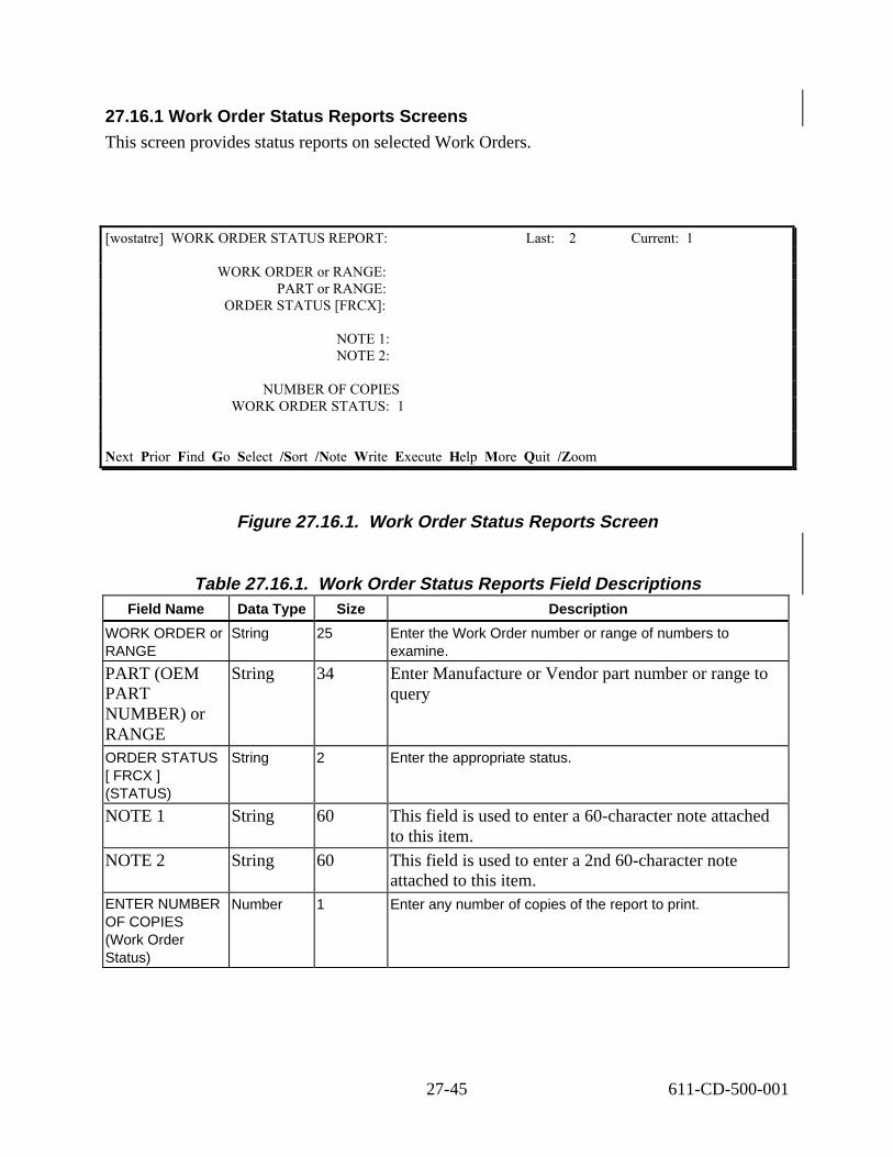
27.16.1 Work Order Status Reports Screens This screen provides status reports on selected Work Orders.
[wostatre] WORK ORDER STATUS REPORT: Last: 2 Current: 1
WORK ORDER or RANGE: PART or RANGE:
ORDER STATUS [FRCX]:
NOTE 1: NOTE 2:
NUMBER OF COPIES WORK ORDER STATUS: 1
Next Prior Find Go Select /Sort /Note Write Execute Help More Quit /Zoom
Figure 27.16.1. Work Order Status Reports Screen
Table 27.16.1. Work Order Status Reports Field Descriptions Field Name Data Type Size Description
WORK ORDER or RANGE
String 25 Enter the Work Order number or range of numbers to examine.
PART (OEM PART NUMBER) or RANGE
String 34 Enter Manufacture or Vendor part number or range to query
ORDER STATUS [ FRCX ] (STATUS)
String 2 Enter the appropriate status.
NOTE 1 String 60 This field is used to enter a 60-character note attached to this item.
NOTE 2 String 60 This field is used to enter a 2nd 60-character note attached to this item.
ENTER NUMBER OF COPIES (Work Order Status)
Number 1 Enter any number of copies of the report to print.
27-45 611-CD-500-001

Table 27.16.2 Procedures to generate Maintenance Work Order Reports (1 of 2)
STEP ACTION OCCURRENCE
STEP 1 From the Main Menu
A. Select ILM Main Menu – press ‘enter’
B. Select Maintenance Menu – press ‘enter’
C. Select Work Order Status Reports – press ‘enter’
This will give you the Work Order Status Reports screen.
STEP 2 Press ‘/a’ to go into add mode.
STEP 3 Fill in the necessary information. This report can be run without filling in any fields except “NUMBER OF COPIES,”
Fill in selection criteria for the other fields as required.
A. Enter the Work order number, or you may press ‘/z’, choose the work order from the list by pressing ‘t’, then press ‘F3’.
B. Enter the child OEM part number - you may press ‘/z’, choose the OEM Part from the list by pressing ‘t’, then press ‘F3’.
C. Enter order status
Null- OPEN – when the order is first entered
‘F’- Firm – when the order is being reviewed by the ILS MC.
‘R’- Release – when the order is being reviewed by the ILS PA.
‘C’ – Closed – when the order is closed.
D. Enter any note to appeal on the header of the report
E. Enter number of copies of the report to print.
STEP 4 Press ‘F3’ to exit the add mode.
STEP 5 Press ‘e’ to execute the transaction. A Report Destination prompt will come up that allow you to select the location where you want the report to go.
STEP 6 Press ‘F3’ if you do NOT want to print the report. If you want to print it on the screen, choose option 1 and press ‘enter’.
A formatted report will come up. You have several options:
Next/Previous/Right/Quit/Hardcopy?
27-46 611-CD-500-001

Table 27.16.2. Procedures to generate Maintenance Work Order Reports (2 of 2)
STEP ACTION OCCURRENCE
STEP 7 A. Make your selection
-Press ‘n’ for Next
-Press ‘p’ for Previous
-Press ‘r’ for Right
-Press ‘q’ for Quit or
-Press ‘h’ to print a hardcopy of the report
B. After finished making your selection, press ‘a’ to exit the report screen.
C. A message will come up specifying the number of reports generated, press ‘enter’.
D. Another message will prompt up “Another?”
-Press ‘y’ if you want to print more report. This will take you back to the Work Order Status reports screen, or
-Press ‘n’, this will take you back to the Maintenance Menu.
Remember to press <ENTER> after each field.
PLEASE NOTE the Maintenance Menu options for the following are reserved for the ILS Maintenance Coordinator and ILS Property Administrators. The view option is available for information only. The ILS Maintenance Coordinator and Property Administrators will maintain the add/modify/deletion for these options.
1. Maintenance Codes
2. Maintenance Contracts
3. Authorized Employees
27-47 611-CD-500-001

27.17 Maintenance Codes Screens This screen provides failure codes and descriptions for use with repairs and replacements.
[mntcode] MAINTENANCE CODES: Last: 10 Current: 1CODE DESCDT Data transmissionDG Display geometryDD Dim displayCON Configuration problemCOL Poor colorCAN Cannot accessBUS Bus errorsBSC Blank screenARC ArcingFCO Field change order
Next Prior View Find Go Select /Sort /Note Help More Quit
Figure 27.17-1. Maintenance Codes Screen
27.17.1 Maintenance Contracts Screens This screen provides contract numbers for repair contracts with vendors and suppliers.
[mntcont] MAINTENANCE CONTRACTS: Last: 10 Current: 1
CONTRACT ID: SILPGM Zoom to related items
VENDOR: SUN
START DATE: 01/10/97
END DATE: 12/31/98
PO NUMBER: TIM1 PIN: SC21534
Next Prior View Find Go Select /Sort /Note Help More Quit /Zoom
Figure 27.17.1-1. Maintenance Contracts Screen
27-48 611-CD-500-001

Table 27.17.1-1. Maintenance Codes Field Descriptions Field Name Data Type Size Description
CODE (maintenance)
String 2 The user will enter any desired code (to be described in DESC) in this field.
DESC (maintenance)
String 30 Enter the description of the (maintenance) code.
Table 27.17.1-2. Maintenance Contracts Field Descriptions Field Name Data Type Size Description
CONTRACT ID String 15 The actual ID as assigned by Purchasing or provided by the vendor.
VENDOR String 6 The Vendor code whom the item was purchased from.
START DATE Date 8 Date the contract is to become effective.
END DATE Date 8 Date the contract will expire.
PO NUMBER String 10 Database changes are reserved to the ILS PA.
PIN String 20 PIN number applicable for authorization for vendor contact.
27.17.2 Authorized Employees Screens
This screen provides employee codes for employees who have been permitted access to the vendor for repair notification.
[mntem] AUTHORIZED EMPLOYEES: Last: 8 Current: 1 EMPL CONTRACT NO VENDOR Last Name 266 SILPGM SUN Roach 266 SYBASE SYB Roach 370 SYBASE SYB Gallagher 370 TEST1 SUN Gallagher 370 Test1 SUN Gallagher 407 457891 AAC Kennedy 407 SILPGM Kennedy 407 SYBASE Kennedy
Next Prior View Find Go Select /Sort /Note Help More Quit /Zoom
Figure 27.17.2-1. Authorized Employees Screen
27-49 611-CD-500-001

Table 27.17.2-1. Authorized Employees Field Descriptions Field Name Data Type Size Description
EMPL String 10 The employee code.
CONTRACT NO String 10 The maintenance contract number.
VENDOR String 6 The Vendor code whom the item was purchased from.
Last Name String 30 The employee last name from the employee master file.
27.18 ILM Master Menu The ILM Master Menu provides the LMC with the ability to verify the accuracy of ILM in reference to employee information, inventory location, hardware and software codes and OEM Part Numbers All additions, deletions or modifications are to be directed to the ILS Property Administrator.
ECS Management System ilmastm ILM Master Menu 11/11/98 12:56
1. Employee Manager 2. Inventory Location Manager 3. Hardware Software Codes 4. OEM Part Number
Please enter selection (1-4 or name): ----------------
F1-help F3-prior menu F5-select F8-exit
Figure 27.18-1. ILM Master Menu
The ILM Master menu is broken down into the following functions:
Table 27.18-1. ILM Master Menu options Menu item Function Section
Employee Manager Provides for the maintenance of employee information. 4.1.1
Inventory Location Manager
Provides for the maintenance of location information used in the inventory and logistics processes.
4.1.2
Hardware/Software Codes
Provides the maintenance of the codes used to identify maintenance cost source information in the inventory and logistics processes.
4.1.3
OEM Part Numbers Provides for the maintenance of OEM Part Numbers information used in the inventory and logistics processes
4.1.4
27-50 611-CD-500-001

27.18.1 Employee Manager Screens This screen provides for the maintenance of employee information.
[sfempmnt] EMPLOYEE MANAGER: Last: 900 Current: 1
EMPLOYEE NUMBER: 00000000001 LAST NAME: Lam FIRST NAME: Tan
STATUS:
WORK CENTER: EDF : ECS Development Facility
PHONE: 301-925-0726 FAX NUMBER: 301-925-0741
E-MAIL: [email protected] PAGER NUMBER:
CC MAIL: Lam, Tan
Next Prior View Find Go Select /Sort /Note Help More Quit
Figure 27.18.1-1. Employee Manager Screen
Table 27.18.1-1. Employee Manager Field Descriptions Field Name Data Type Size Description
EMPLOYEE NUMBER (EMPL)
String 10 Enter the employee code.
LAST NAME (EMPLOYEE)
String 30 Last name of the employee described by the displayed code.
FIRST NAME (EMPLOYEE)
String 30 First name of the employee described by the displayed code.
STATUS (EMPLOYEE)
String 1 Status of the employee described by the displayed code.
WORK CENTER (EMPLOYEE)
String 6 Work Center (normally assigned) of the employee described by the displayed code.
PHONE (EMPLOYEE)
String 18 Telephone number of the employee described by the displayed code.
FAX NUMBER (EMPLOYEE)
String 13 FAX number of the employee described by the displayed code.
E-MAIL (EMPLOYEE)
String 30 Enter employee’s e-mail address.
PAGER NUMBER (EMPLOYEE)
String 13 Pager Number of the employee described by the displayed code.
CC MAIL (EMPLOYEE)
String 30 CC-mail address of the employee described by the displayed code.
27-51 611-CD-500-001

27.18.1.2 Inventory Location Manager Screens
This screen provides for the maintenance of location information used in the inventory and logistics processes.
[imlocns] LOCATION MASTER MANAGER: Last: 13 Current: 1
MATERIAL LOCATION ID: ARC DESCRIPTION: Archive Location
LOCATION TYPE: A [Null or S = Stock R = received N = non-nettable W =work center A = archive]
SITE: EDF
SHIPPING CENTER NUMBER: 0 SHIPPING REPORT ALPHA:
CONSIGNEE NAME: EDF SITE PROPERTY MANAGER ADDRESS 1: 1616A MCCORMICK DRIVE ADDRESS 2:
CITY: Upper Marlboro STATE: MD
ZIP: 20785 PHONE: (301) 925-0702
Next Prior View Find Go Select /Sort /Note Help More Quit
Figure 27.18.1.2-1. Inventory Location Manager Screen
Table 27.18.1.2-1. Inventory Location Manager Field Descriptions (1 of 2) Field Name Data Type Size Description
MATERIAL LOCATION ID
String 6 ID for the location where material can be found.
DESCRIPTION (Material Location)
String 30 Text description of the utility of the site.
LOCATION TYPE (Material Location)
String 1 Specifies the material application at the site: Null or S = stock, R = received, N = non-nettable, W = work center, A = archive.
SITE (LOCATION) String 6 This field is used to designate the actual location or site of where the item is.
SHIPPING REPORT NUMBER
Number 2 This field is the report number assigned to this item when the item was shipped.
SHIPPING REPORT ALPHA
String 2 Shipping report code associating an alpha code to a numeric site code. See Shipment Numbers by Site screen (shipno).
27-52 611-CD-500-001

Table 27.18.1.2-1. Inventory Location Manager Field Descriptions (2 of 2) Field Name Data Type Size Description
CONSIGNEE NAME
String 30 Name of individual/office responsible for material at the site.
ADDRESS 1 (Consignee)
String 30 First part of address
ADDRESS 2 (Consignee)
String 30 Second part of address.
CITY String 20 City part of address
STATE String 2 State 2 character abbreviation of address.
ZIP String 10 Zip code of address.
PHONE String 18 Telephone number of address
27.18.2 Hardware/Software Codes Screens
This screen provides the maintenance of the codes used to identify maintenance cost source information in the inventory and logistics processes.
CODE DESCRIPTIONH HARDWAREHD HARDWARE DOCUMENTATIONHF FIRMWAREHG HARDWARE SUPPORTHU HARDWARE UPDATEMC MSTR MAINTENANCE CONTRACTS SOFTWARESD SOFTWARE DOCUMENTATIONSO OPERATING SYSTEMSU SOFTWARE UPGRADET TRAINING
Next Prior View Find Go Select /Sort /Note Help More Quit
Figure 27.18.2-1. Hardware/Software Codes Screen
Table 27.18.2-1. Hardware/Software Codes Field Descriptions Field Name Data
Type Size Description
CODE (Hardware/Software)
String 10 The user will enter any desired (Hardware/Software) code in this field.
DESCRIPTION (Hardware/Software)
String 30 Enter the description of the (Hardware/Software) code.
27-53 611-CD-500-001

27.18.3 OEM Part Numbers
This screen provides for the maintenance of OEM Part Number information used in the inventory and logistics processes.
[eompart] OEM PART NUMBERS: Last: 3528 Current: 1 OEM PART: +KTH4P/8 OEM MFG: HPC
MODEL/VERSION: OEM DESCRIPTION: 8 MB RAM for HP Laser jet 5SI (1 x 8 SIMM CONTROL ITEM ID: NSIb0000053
VENDOR: HPC COST: 240.00
HW/SW CODE: H YEAR MFG: 1996
MEDIA CODE: MEDIA:
Next Prior View Find Go Select /Sort /Note Help More Quit
Figure 27.18.3-1. OEM Part Numbers Screen
Table 27.18.3-1. OEM Part Numbers Field Descriptions Field Name Data Type Size Description
OEM PART (Part number)
String 34 This is the manufacturer’s part number of the item being cataloged
OEM MFG String 40 This is the name of the manufacturer.
MODEL/ VERSION
String 24 This field is used to enter the actual Model and or Version of the item.
OEM DESCRIPTION
String 30 This field reflects the description of the Oem Part Number entered in the field above.
CONTROL ITEM ID
String 20 Database changes are reserved to the ILS PA.
VENDOR (Part numbers)
String 6 The vendor of the item.
COST Floating 9.2 This field is the purchase cost of the item.
HD/SW CODE String 10 This field provides a code designating the type of item.
YEAR MFG String 4 This field is the actual 4-digit year the item was manufactured. This field defaults to the current year.
MEDIA CODE String 1 Code for Media identification
MEDIA String 2 Media material
27-54 611-CD-500-001

28. Procedure for Removing Archived Files from the PDR Server Staging Areas
28.1Overview
28.1.1 PDR Server MODAPS Area
The MODAPS PDR Server does not automatically perform a file deletion after data is "pulled" from MODAPS for ingest to MODAPS data server.
Auto - Primary Method
MODAPS will generate a e-mail/ftp notification back to GDAAC PDR sever account after successful ingest into MODAPS. After MODAPS notification is received, the cronjob or "<MODAP delete script>" will delete selected files from the PDR partitioned staging area based upon the e-mail/ftp notification.
Manual - Backup Method
Initiate a Tivoli monitor which manages a partition on a "% full" basis. If the partition is more than 80 % full run the following:
<prompt>$ find /MODOPS/GSFC/ -follow -atime +1 -exec \rm -f {} \;which deletes any files not acessed for a day which should free up enough for the currentdays.
28.1.2 PDR Server DAAC Areas Note: Each respective DAAC is responsible for deleting, from the respective PDR
partition/staging area, files that were successfully archived in their respective at the local DAAC.
Auto - Primary Method
The deletion of files from the DAAC area will be done via cron for each DAAC account to run a script every two hours. The script is designed to be run with a directory as an argument i.e. /<path_to_script/PDR_parser <path_to_PAN>.
Manual - Backup Method
Before deleting any files from the PDR Server Partition/Staging area, access the Ingest Subsystem and verify that those files to be deleted are listed in the "InRequestSummaryHeader" table. (See Ingest procedure 16.4.4 - Ingest Archive Verification).
Addendum 1 28-1 611-CD-500-001

28.2PDR Server File Deletion Procedure Step 1 Log on to any workstation using your user identifier and password by typing
YourUserId, and then press Return. A password prompt is displayed
Step 2 Enter Your Password, then press Return. You are authenticated as yourself
Step 3 Enter telnet <hostname>.
Step 4 Enter YourUserID, and then press Return A password prompt is displayed
Step 5 Enter Your Password, then press Return You are authenticated as yourself
Step 6 Set your terminal display environment using the following command: Setenv DISPLAY <hostname>:0.)>
Step 7 Change directory to the directory containing the <"MODAPS delete script>" file: cd/usr/ecs/<mode>/CUSTOM/utilities
Step 8 Enter ls to list the content of the directory:
Step 9 Execute the "<MODAPS delete script>" using the following command: "<MODAPS delete script"> <path name> <number of days>
Addendum 1 28-2 611-CD-500-001

Appendix A. Additional Material
TBS
A-1 611-CD-500-001

This page intentionally left blank.
A-2 611-CD-500-001

Abbreviations and Acronyms
Ao Operational Availability
ACL Access Control List
ADC Affiliated Data Center (NOAA)
ADSERV Advertising Service
AI&T Algorithm Integration and Test
AIT Algorithm Integration Team
AMASS Archival Management and Storage System
ASCII American Standard Code for Information Interchange
BBS Bulletin Board System
CCB Configuration Control Board (NASA Convention)
CCR Configuration Change Request
CCRS Canada Centre for Remote Sensing
C D Compact Disk
CDE Common Desktop Environment
CD-ROM Compact Disk - Read Only Memory
CDR Critical Design Review
CDRL Contract Data Requirements List
CDS Cell Directory Service
CHCI Communications Hardware Configuration Item
CHUI Character User Interface
Configuration Item
CIDM Client Interoperability and Data Management
C M Configuration Management
CMA CM Administrator
CN Change Notice
CO Contracting Officer
AB-1 611-CD-500-001
CI

COTR Contracting Officer’s Technical Representative
COTS Commercial Off-the-Shelf (hardware or software)
CPU Central Processing Unit
CR Change Request
CRM Change Request Manager
CSCI Computer Software Configuration Item
CSMS Communications and Systems Management Segment (ECS)
CSR Consent To Ship Review
CSS Communication Subsystem
DAA Data Availability Acknowledgment
DAAC Distributed Active Archive Center
DADS Data Archive and Distribution System
DAN Data Availability Notice
DAP Delivered Algorithm Package
DAR Data Acquisition Request
DAS Data Availability Schedule
DAT Digital Audio Tape
DB Database
DBA Database Administrator
DBMS Database Management System
DCE Distributed Computing Environment (OSF)
DCF Data Capture Facility
DCN Document Change Notice
DCO Document Change Order
DCR Data Collection Request
DD Data Dictionary
DDA Data Delivery Acknowledgment
DDICT Data Dictionary
DDIST Data Distribution
AB-2 611-CD-500-001

DDN Data Delivery Notice
DDSRV Document Data Server
DDTS Distributed Defect Tracking System
DES Data Encryption Standard
DESKT Desktop Configuration Item
DID Data Item Description
DIF Data Interchange Formant
DIMGR Distributed Information Manager
DME Distributed Management Environment
DMO Data Management Organization
DNS Domain Name Service
DOF Distributed Object Framework
DPR Data Processing Request
DPS Data Processing Subsystem
DR Delivery Record
DS Data Server
DSS Data Server Subsystem
e-mail Electronic Mail
EBNet EOSDIS Backbone Network (combines Ecom and ESN)
ECN Equipment Control Number
ECS EOSDIS Core System
EDC EROS Data Center (DAAC)
EDF ECS Development Facility
EDHS ECS Data Handling System
EGS EOS Ground System
EIN Equipment Identification Number
EMC Enterprise Monitoring and Coordination
EOC EOS Operations Center (ECS)
EOS Earth Observing System
AB-3 611-CD-500-001

EOSDIS Earth Observing System Data and Information System
EP Evaluation Package
EROS Earth Resources Observation System
ESD Electrostatic Discharge
ESDIS Earth Science Data and Information System (GSFC Code 505)
ESDT Earth Science Data Type
ESOD Earth Science On-line Directory
ET Eastern (standard or daylight savings) Time
FDDI Fiber Distributed Data Interface
FORTRAN FORmula TRANslation (computer language)
FOS Flight Operations Segment (ECS)
FOT Flight Operations Team
FTP File Transfer Protocol
FTPD File Transfer Protocol Daemon
GB Gigabyte (109)
Gb Gigabit (109)
GBps Gigabytes per Second
Gbps Gigabits per Second
GCDIS Global Change Data and Information System
GCMD Global Change Master Directory
GFE Government Furnished Equipment
GFP Government Furnished Property
GSFC Goddard Space Flight Center
GUI Graphical User Interface
H/W Hardware
HDF Hierarchical Data Format
HIPPI High Performance Parallel Interface
HPOV HP Open View
HSM Hierarchical Storage Management
AB-4 611-CD-500-001

HTML Hypertext Mark-Up Language
HWCI Hardware Configuration Item
I&AT Integration and Acceptance Test
I&T Integration and Test
I&TT Integration and Test Team
IATO Independent Acceptance Test Organization
ICD Interface Control Document
ICLHW Ingest Client Hardware [configuration item]
ILM Inventory, Logistics, and Maintenance
ILP Integrated Logistics Plan
ILS Integrated Logistics Support
ILSMT ILS Management Team
ILSO ILS Office
INGST Ingest Services
INS Ingest System
IOS Interoperability Subsystem
IP Internet Protocol
IQ Intelligent Query and IQ Access
Ir1 Interim Release 1
ISDN Integrated Services Digital Network
ISS Internetworking Subsystem
ISQL Interactive SQL
IV&V Independent Verification and Validation
JIL Job Information Language
JPL Jet Propulsion Laboratory (DAAC)
KB Kilobyte (103)
Kb Kilobit (103)
KBps Kilobytes per Second
AB-5 611-CD-500-001

Kbps Kilobits per Second
L-7 Landsat-7 (Landsat-7 for EDHS search)
L0 Level 0
L0-L4 Level 0 (zero) through Level 4 (use Level-0 through Level-4 for EDHS search)
LAN Local Area Network
Landsat Land Remote-Sensing Satellite
LaRC Langley Research Center (DAAC)
LDOS Landsat Data and Operations System
LIM Local Information Manager
LIMGR Local Information Manager
LMC Local Maintenance y
Loral Loral Aerosys (ECS Team)
LRU Line Replaceable Unit
M Million, mega (prefix)
M&O Maintenance and Operations
MAN Metropolitan Area Network
MB Megabyte (106)
Mb Megabit (106)
MBps Megabytes per Second
Mbps Megabits per Second
MCF Metadata Configuration File Metadata Control File
MD Master Directory
MDA Management Data Access
MDT Mean Downtime
MHWCI Management Hardware Configuration Item
MHz Megahertz
MIB Management Information Base
MIS Management Information System
AB-6 611-CD-500-001

MM Millimeter
MO&DSD Mission Operations and Data Systems Directorate (GSFC Code 500)
MOU Memorandum of Understanding
MR Malfunction Report
MSEC Millisecond
MSFC Marshall Space Flight Center (DAAC)
MSS Management Systems Subsystem
MTBCM Mean Time Between Corrective Maintenance
MTBF Mean Time Between Failure
MTBM Mean Time Between Maintenance
MTBPM Mean Time Between Preventive Maintenance
MTPE Mission to Planet Earth
MTTR Mean Time to Repair
MTTRes Mean Time to Restore
N/A Not Applicable
NA Network Administrator
NASA National Aeronautics and Space Administration
Nascom NASA Communications
NCC Network Control Center (GSFC) network communication center
NCR Nonconformance Report
NCS Netscape Commerce Server
NCSA National Center for Supercomputer Applications
NMCI Network Management Configuration Item
NNM HPOpenView Network Node Manager
NOAA National Oceanic and Atmospheric Administration
NSI NASA Science Internet
NWCI Networking Configuration Item
OEM Original Equipment Manufacturer
AB-7 611-CD-500-001

OJT On-the-Job Training
OPS Operations
Ops Super Operations Supervisor
ORPA Operations Readiness & Performance Assurance
ORR Operations Readiness Review
OS Operating System
OSF Open Software Foundation
OTS Off the Shelf
OVW HP OpenView Windows
PAIP Performance Assurance Implementation Plan
PB Petabyte (1015 )
PC Personal Computer Process Control
PCF Process Control File
PDL Program Design Language
PDPS Planning and Data Processing System
PGE Product Generation Executive
PGS Product Generation Service
PI Principal Investigator
PIN Password Identification Number
PLANG Production Planning CSCI
PLNHW Planning Hardware [configuration item]
PLS Planning Subsystem
PM Preventative Maintenance
PPM Principal Period of Maintenance
PR Production Request
QA Quality Assurance
QC Quality Control
QRU Query, Retrieve, and Update
AB-8 611-CD-500-001

R&M Reliability and Maintainability
RAID Redundant Array of Inexpensive Disks
RAM Random Access Memory
RE Responsible Engineer
RID Review Item Discrepancy
RMA Return Material Authorization
RMS Resource Management Subsystem
RSM Replication Server Manager
RSSD Replication Server System Database
Spacecraft
S/W Software
S/WCI Software Configuration Item
SA System Administrator
SATAN Security Administrator Tool for Analyzing Networks
SCDO Science and Communications Development Office (ECS)
SCF Science Computing Facility
SCSI Small Computer System Interface
SDP Science Data Processing
SDPF Science Data Processing Facility
SDPS Science Data Processing Segment (ECS)
SDPS/W Science Data Production Software
SDPTK Science Data Processing Toolkit
SDSRV Science Data Server
SE System Engineering
SE&I System Engineering and Integration
SEI&T System Engineering, Integration, and Test
SEO Sustaining Engineering Organization
SEPG Software Engineering Process Group
SGI Silicon Graphics Incorporated
AB-9 611-CD-500-001
S/C

SI&T System Integration and Test
SMC System(s) Monitoring and Coordination Center
SMF Status Message Facility
SMTP Simple Mail Transport Protocol
SNMP Simple Network Management Protocol
SOR System Operations Review
SORR Segment Operational Readiness Review
SPRHW Science Processing Hardware [configuration item]
SQL Structured Query Language
SQR SQL Report Writer
SRR System Requirements Review
SSAP Science Software Archive Package
SSI&T Science Software Integration and Test
SSL Secure Socket Layer
STMGT Storage Management
T&M Time and Materials
TB Terabyte (1012)
TBC To Be Confirmed
TBD To Be Determined
TBR To Be Resolved
TBS To Be Supplied
Tbyte Terabyte
TCP/IP Transmission Control Protocol/Internet Protocol
TEC Tivoli Enterprise Console
telecon Telephone Conference
TELNET Telecommunication Network
TRMM Tropical Rainfall Measurement Mission
TSDIS TRMM Science Data and Information System
AB-10 611-CD-500-001

TT Trouble Ticket
UDP User Datagram Protocol
UR Universal Reference
URDB User Recommendations Database
URL Universal Resource Locator
USO User Support Office
US Rep User Services Representative
UWG User Working Group
VDD Version Description Document
VOB Versioned Object Base (ClearCase)
WAIS Wide Area Information Server
WAN Wide Area Network
WKBCH Workbench
WKSHCI Working Storage Hardware Configuration Item
WWW World Wide Web
AB-11 611-CD-500-001

This page intentionally left blank.
AB-12 611-CD-500-001