12 lead ecg simulator - gaumard - patient simulators for
TRANSCRIPT

HAL® S1020 Instructional Manual
12 Lead ECG Simulator
Contains documentation for HAL S1020 and GIGA™ Module
HAL is an interactive educational system developed to assist a certified instructor. It is not a substitute for a comprehensive understanding of the subject matter
and not intended for clinical decision making.
Manual Version H.11.9.1 Copyright 2004-2011
All Rights Reserved www.Gaumard.com

Instruction Manual GIGA Module/HAL S1020
Contents I. End User License Agreement ................................................................................................... 4 II. Getting Started .................................................................................................................... 6
A. Overview ............................................................................................................................ 7 B. Terminology ........................................................................................................................ 8 C. Equipment Set-up ................................................................................................................ 9
Leg Assembly ................................................................................................................... 9 1. Battery Connection ......................................................................................................... 10 2. Communication Module ................................................................................................... 11 3. Connecting Monitor/Defibrillator Leads ............................................................................. 12 4.
III. Working with GIGA™ Module .............................................................................................. 13 A. Startup ............................................................................................................................. 14 B. Profiles Menu .................................................................................................................... 14 C. Environment ..................................................................................................................... 17
Status ........................................................................................................................... 17 1. Details ........................................................................................................................... 18 2.a) Heart Rate .................................................................................................................. 20 b) Heart Rhythm ............................................................................................................. 20 c) ECG Designer ............................................................................................................. 21 Myocardial Infarction Model ............................................................................................ 25 3. Palette .......................................................................................................................... 31 4. Scenario ........................................................................................................................ 33 5.a) Adding a palette ......................................................................................................... 34 b) Scenario Controls ........................................................................................................ 34 c) Scenario Automatic-Responses ..................................................................................... 36 Right Panel .................................................................................................................... 37 6.a) ECG graph .................................................................................................................. 37 b) Log ............................................................................................................................ 39
D. Bottom Menu .................................................................................................................... 40 Signal ............................................................................................................................ 40 1. Battery .......................................................................................................................... 40 2. Session Time ................................................................................................................. 40 3. Trending time ................................................................................................................ 41 4. Stand-By ....................................................................................................................... 41 5.
E. Top Menu ......................................................................................................................... 42 File ............................................................................................................................... 42 1.a) Profile ........................................................................................................................ 42 b) New Session ............................................................................................................... 43 c) Save Report ................................................................................................................ 43 d) Print Report ................................................................................................................ 44 e) Exit ............................................................................................................................ 44 Set-up ........................................................................................................................... 45 2.a) Options ...................................................................................................................... 45 b) Non-Scenario Auto Responses ...................................................................................... 45 Help .............................................................................................................................. 48 3.a) Diagnostics ................................................................................................................. 48 b) Help ........................................................................................................................... 49 c) About ......................................................................................................................... 49 Shock Panel ................................................................................................................... 50 4.

Instruction Manual GIGA Module/HAL S1020
Evaluation ..................................................................................................................... 50 5.IV. Care and Cautions ............................................................................................................. 54
A. Overall Warnings ............................................................................................................... 55 B. Electrical therapy ............................................................................................................... 55
V. Appendix .............................................................................................................................. 57 A. More about Scenarios ........................................................................................................ 58 B. File Structure .................................................................................................................... 60 C. Troubleshooting ................................................................................................................ 61 D. Warranty .......................................................................................................................... 61 E. Contact Us ........................................................................................................................ 63

Instruction Manual GIGA Module/HAL S1020
4
I. End User License Agreement This is a legal agreement between you, the end user, and Gaumard® Scientific Company, Inc. (“Gaumard”). This software is protected by copyright laws and remains the sole property of Gaumard. By installing the GaumardUI
(the "Software") media, you agree to be bound by the terms of this agreement. If you do not agree to the terms
of this agreement, promptly return the uninstalled media and accompanying items to Gaumard at the address indicated below.
1. Grant of License. Gaumard hereby grants to you (an individual or institution) the right to install and activate
the Software on one computer for use with one Interactive patient simulator system. The software may also be
installed on any number of other computers at the same institution so that students may access the learning resources. One copy of the software may be made for backup purposes. You may not network this Software, or
allow multiple users unless you purchased a multi-user workstation license. Sharing this Software with other individuals or allowing other individuals to view the contents of this Software is in violation of this license.
2. Copyright. The Software is owned by Gaumard and protected by United States copyright laws and international treaty provisions. Therefore, you must treat this Software like any other copyrighted material. You
may not make this Software or copies thereof available in any manner or form or use, copy or transfer the Software, in whole or in part, except as provided herein.
3. Other Restrictions. You may not rent or lease this Software to any other party. You may not alter, merge,
modify, adapt, reverse engineer, decompile or disassemble the software, or disclose the contents of this Software
to any other party.
4. Electronic Transmission of Software. If you received the Software by electronic transmission or by Internet delivery, by installation of the Software, you acknowledge that you have read and understand this license
agreement and agree to be bound by its terms and conditions.
5. Term of Agreement. The term of this Agreement and the license granted to you pursuant hereto shall
commence upon installation of this Software. This Agreement and the license granted herein may otherwise be terminated by Gaumard in the event that you are in breach of any provision of this Agreement. In the event of
termination, you agree to immediately return this Software, accompanying items, and any copies thereof to Gaumard.
6. LIMITED WARRANTY
(A) THE CD-ROM MEDIA (THE "MEDIA") WHICH CONTAINS THIS SOFTWARE IS WARRANTED, FOR A PERIOD
OF 30 DAYS FROM THE DATE OF PURCHASE, TO BE FREE FROM DEFECTS IN MATERIAL AND WORKMANSHIP.
ELECTRONIC TRANSMISSION IS WARRANTED TO BE FREE FROM DEFECTS AT THE MOMENT OF
TRANSMISSION. YOUR SOLE AND EXCLUSIVE REMEDY, AND GAUMARD'S SOLE LIABILITY, IS TO REPLACE THE
DEFECTIVE MEDIA OR TO REPEAT THE ELECTRONIC TRANSMISSION PROVIDED THAT YOU NOTIFY GAUMARD
IN WRITING OF SUCH DEFECT OR DEFECTIVE TRANSMISSION AND RETURN THE DEFECTIVE MEDIA, IF ANY,
DURING THE 30-DAY WARRANTY PERIOD.

Instruction Manual GIGA Module/HAL S1020
5
(B) EXCEPT AND TO THE EXTENT EXPRESSLY PROVIDED IN PARAGRAPH (A), THE SOFTWARE AND
ACCOMPANYING WRITTEN MATERIALS ARE PROVIDED ON AN "AS IS" BASIS, WITHOUT ANY WARRANTIES OF
ANY KIND, INCLUDING, BUT NOT LIMITED TO, ANY IMPLIED WARRANTIES OF MERCHANTABILITY OR FITNESS
FOR ANY PARTICULAR PURPOSE. NO ORAL OR WRITTEN INFORMATION OR ADVICE GIVEN BY GAUMARD, ITS
DEALERS, DISTRIBUTORS, AGENTS OR EMPLOYEES SHALL CREATE A WARRANTY OR IN ANY WAY INCREASE
THE SCOPE OF THIS WARRANTY, AND YOU MAY NOT RELY ON ANY SUCH INFORMATION OR ADVICE.
GAUMARD DOES NOT WARRANT, GUARANTEE, OR MAKE ANY REPRESENTATIONS REGARDING THE USE OR
THE RESULTS OF USE, OF THE SOFTWARE OR WRITTEN MATERIALS IN TERMS OF CORRECTNESS, ACCURACY,
RELIABILITY, CURRENTNESS, OR OTHERWISE, AND THE ENTIRE RISK AS TO THE RESULTS AND
PERFORMANCE OF THE SOFTWARE IS ASSUMED BY YOU. IF THE SOFTWARE OR WRITTEN MATERIALS ARE
DEFECTIVE, YOU AND NOT GAUMARD OR ITS DEALERS, DISTRIBUTORS, AGENTS, OR EMPLOYEES, ASSUME
THE ENTIRE COST OF ALL NECESSARY SERVICING, REPAIR OR CORRECTION OTHER THAN EXPRESSLY
DESCRIBED ABOVE.
(C) NEITHER GAUMARD NOR ANYONE ELSE WHO HAS BEEN INVOLVED IN THE CREATION, PRODUCTION OR
DELIVERY OF THIS PRODUCT SHALL BE LIABLE FOR ANY DIRECT, INDIRECT, CONSEQUENTIAL OR INCIDENTAL
DAMAGES (INCLUDING DAMAGES FOR LOSS OF BUSINESS PROFITS, BUSINESS INTERRUPTION, LOSS OF
BUSINESS INFORMATION, AND THE LIKE) ARISING OUT OF THE USE OR INABILITY TO USE SUCH PRODUCT
OR RELATED TO THIS AGREEMENT EVEN IF GAUMARD HAS BEEN ADVISED OF THE POSSIBILITY OF SUCH
DAMAGES. GAUMARD SHALL NOT BE LIABLE TO YOU FOR ANY INDIRECT, SPECIAL, INCIDENTAL, OR
CONSEQUENTIAL DAMAGES OR LOST PROFITS ARISING OUT OF OR RELATED TO THIS AGREEMENT OR YOUR
USE OF THE SOFTWARE AND/OR THE RELATED DOCUMENTATION, EVEN IF GAUMARD HAS BEEN ADVISED OF
THE POSSIBILITY OF SUCH DAMAGES. IN NO EVENT SHALL GAUMARD'S LIABILITY HERE UNDER, IF ANY,
EXCEED THE PURCHASE PRICE PAID BY YOU FOR THE SOFTWARE.
ALL RIGHTS NOT EXPRESSLY GRANTED IN THIS LICENSE AGREEMENT ARE RESERVED BY GAUMARD.
ACKNOWLEDGMENT
BY INSTALLATION OF THIS SOFTWARE, YOU ACKNOWLEDGE THAT YOU HAVE READ AND
UNDERSTAND THE FOREGOING AND THAT YOU AGREE TO BE BOUND BY ITS TERMS AND
CONDITIONS. YOU ALSO AGREE THAT THIS AGREEMENT IS THE COMPLETE AND EXCLUSIVE
STATEMENT OF AGREEMENT BETWEEN THE PARTIES AND SUPERSEDES ALL PROPOSED OR PRIOR
AGREEMENTS, ORAL OR WRITTEN, AND ANY OTHER COMMUNICATIONS BETWEEN THE PARTIES
RELATING TO THE LICENSE DESCRIBED HEREIN.

Instruction Manual GIGA Module/HAL S1020
6
II. Getting Started
Instruction Manual GIGA Module/HAL S1020
7
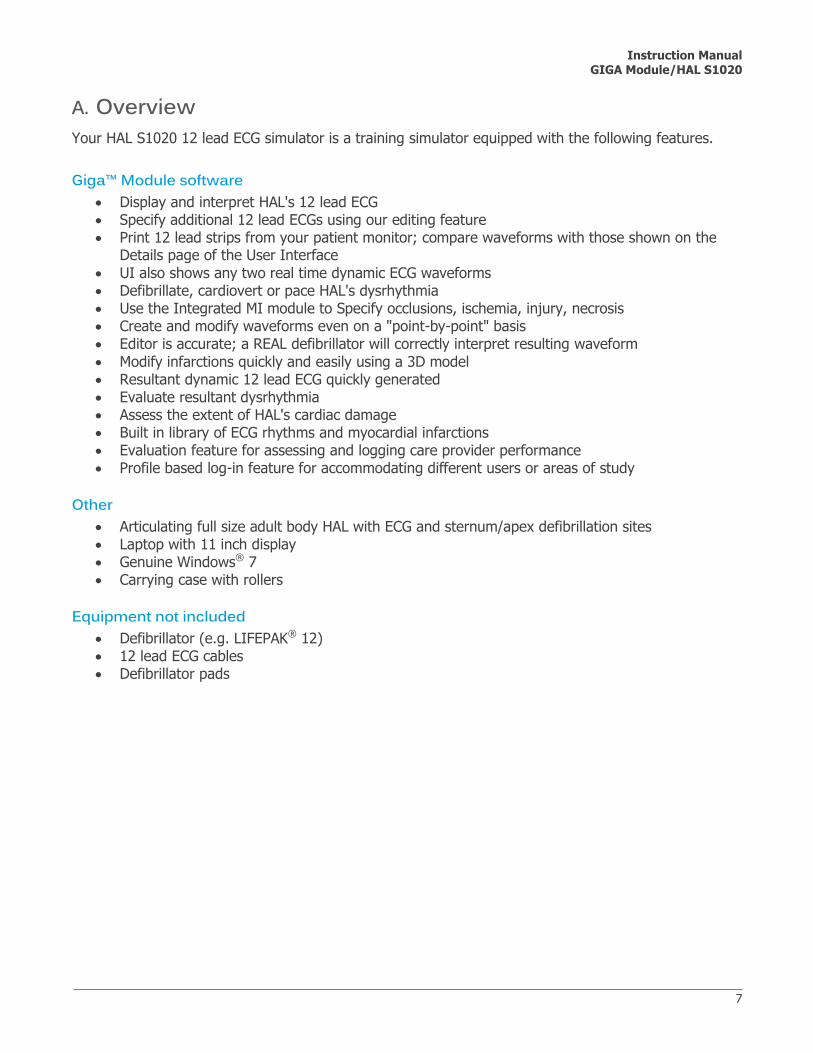
A. Overview Your HAL S1020 12 lead ECG simulator is a training simulator equipped with the following features.
Giga™ Module software
Display and interpret HAL's 12 lead ECG Specify additional 12 lead ECGs using our editing feature Print 12 lead strips from your patient monitor; compare waveforms with those shown on the
Details page of the User Interface
UI also shows any two real time dynamic ECG waveforms Defibrillate, cardiovert or pace HAL's dysrhythmia Use the Integrated MI module to Specify occlusions, ischemia, injury, necrosis Create and modify waveforms even on a "point-by-point" basis Editor is accurate; a REAL defibrillator will correctly interpret resulting waveform
Modify infarctions quickly and easily using a 3D model Resultant dynamic 12 lead ECG quickly generated Evaluate resultant dysrhythmia Assess the extent of HAL's cardiac damage Built in library of ECG rhythms and myocardial infarctions Evaluation feature for assessing and logging care provider performance Profile based log-in feature for accommodating different users or areas of study
Other Articulating full size adult body HAL with ECG and sternum/apex defibrillation sites Laptop with 11 inch display Genuine Windows® 7 Carrying case with rollers
Equipment not included Defibrillator (e.g. LIFEPAK® 12) 12 lead ECG cables Defibrillator pads

Instruction Manual GIGA Module/HAL S1020
8
B. Terminology It is wise to spend a moment familiarizing yourself with some of the terminology that will be used to discuss simulation with the HAL system. Facilitator - the person conducting the simulation; an instructor or lab staff member. GIGA Module - the HAL user interface software application, used to control the manikin and evaluate care providers. Palette Item - any full or partial set of physiological parameters that have been grouped and saved together under a single name. Profile - a unique HALUI configuration, including custom Palette, Scenarios, and options. Each Profile acts as a separate program, in that changes made to one profile have no effect on the others. Provider - a person participating in the simulation as a healthcare provider. Scenario - a saved sequence of physiological states, like a "playlist." Scenarios provide a level of automation that unburdens the facilitator and allows standardized presentation of symptoms. Scenario Item - a Palette Item that is part of a scenario. Scenario Items may also represent a fixed delay period ("Wait") or a pause ("Wait Indefinitely").

Instruction Manual GIGA Module/HAL S1020
9
C. Equipment Set-up Leg Assembly 1.
Remove the fixed bolts from the leg joint.
Position the lower leg and insert the joint bolt. Use the two provided hexagonal wrenches to tighten the knee bolts. Do not over tighten the bolts.

Instruction Manual GIGA Module/HAL S1020
10
Battery Connection 2.Locate the connectors on HAL’s right hand side.
Gently lift the right corner on the chest skin as shown and connect the battery plugs.
Slide battery plugs into the cavity and secure the skin.
Finally, connect the charger to the wall outlet and the manikin.

Instruction Manual GIGA Module/HAL S1020
11
Communication Module 3.Connection HAL is powered on when the GIGA Module software is initialized via hardwire connection. Outlined below are the steps for connecting HAL to the control computer.
Connect the Ethernet cable to the communications port and the power adapter located on HAL’s right side.
Connect the Ethernet cable to the USB communication module
Finally, connect the communication module to an available USB port and power on the laptop. The module' can be connected whether the tablet computer is on or off.
The battery indicator will be visible on the Giga Module’s status panel once the software establishes a connection with the manikin. For more information about the communication and battery indicator, refer to Section III.D.2 Warning
Refer to the laptop’s documentation for important information regarding use, charging and care prior to starting the system.
Never disconnect the communications module while the GUI software is running. Doing so can
seriously damage the module.

Instruction Manual GIGA Module/HAL S1020
12
Connecting Monitor/Defibrillator Leads 4.Defibrillation is only allowed on the large sternum and apex sites, circled RED below. NEVER deliver a shock to ECG electrode targets on the shoulders or waist, marked BLUE below. Doing so will not create a fire hazard, nor is there risk of shock to the provider, but internal damage in HAL may result. This situation is considered improper use and is NOT covered by the HAL warranty. The system will require repair at our facility.
There are inherent dangers in the use of some medical devices. For simulations that incorporate electrical therapy of any kind, always know your equipment, and follow the device manufacturers' safety guidelines.
ECG and electrical therapy checklist and warnings: Only deliver electrical therapy when the simulator is fully assembled, dry, and undamaged.
Make sure the defibrillation patches on the simulator are in good condition, including removing any and all gel residue on
the defibrillation patches from previous use(s). It is a good practice to remove gel residues after every use. Failure to do so will leave behind a film of electrode gel that hardens causing arcing and pitting.
Do not re-use the gel-adhesive pads. Do not leave them on for next day use.
Use hard paddles or wet-gel pads preferably. Avoid using solid-gel pads since they present higher risk of burning the simulator’s skin.
Gel pads have a shelf life. Make sure they are not expired to avoid arcing.
Make sure the simulator is not in contact with any electrically conductive surfaces.
Use the simulator only in a well-ventilated area, free of all flammable gases.
NEVER attempt to service or modify any of the electrical connections, especially those between conductive skin sites and the internal electronics. Discontinue use if any wires are found exposed with damaged insulation.
Real medical products, especially electrodes, sometimes use powerful adhesives that can be difficult to remove. A gentle, degreasing cleanser may be needed. Refer to Care and Cautions for more information.
Electrode gel on the skin between any two electrode targets can become a pathway for electrical current, just as in real life. If this occurs, HAL's skin can be burned.
Do not allow defibrillation pads to overlap ECG sites. Doing so will may damage the simulator and cause arcing.
Should dark traces appear on the conductive patches due to gel residue or previous arcing, use a pencil eraser to remove the traces and then clean with alcohol.
DO NOT SCRATCH the conductive patches with abrasive objects; doing so will cause irreversible damage to the conductive sites and subsequently cause arcing

Instruction Manual GIGA Module/HAL S1020
13
III. Working with GIGA™ Module

Instruction Manual GIGA Module/HAL S1020
14
A. Startup To start the simulator, click on the GIGA Module icon on the computer’s home screen.
Select “12 Lead ECG” from the module selection screen and click start.
To troubleshoot connection issues, navigate to Section V.C
B. Profiles Menu A profile is a unique configuration of customized Palettes, Scenarios, and Options. Each profile functions independently, in that changes made to one profile have no effect on the others. After selecting a profile, click load to enter the main window.
The profiles available are the following:
Default Profile – includes one palette with healthy vital signs. When creating a new profile, it is
often useful to include the Default profile contents and begin customization from that foundation.
Quick Start Profile – contains a series of prebuilt palettes and built in scenarios to aid simulation.

Instruction Manual GIGA Module/HAL S1020
15
Profiles are used to organize and protect software settings. Below are some examples on how to use the profile functionality.
It may be appropriate to assign one profile to each user of the HAL system.
Others may choose to create a profile dedicated to a specific academic course, which might be taught by multiple instructors.
For the most detailed exercises, it is sometimes useful to devote an entire profile to one particular subject area, or even one particular scenario.
New Profile Navigate to the left panel and enter a name for the new profile followed by a description.
Include items from other profiles by making the appropriate selection below and click “Create Profile” to finish.

Instruction Manual GIGA Module/HAL S1020
16
When starting out with HAL, it is recommended to use the Quick Start Scenarios profile, which was created in conjunction with experienced healthcare instructors and working medical professionals. See the Factory Preset Profiles appendix for detailed description of the Quick Start Scenarios profile. The Quick Start profile has applicable Palettes that are useful for simulating common medical emergencies. For many applications, it serves a convenient starting point that can be customized to fit most simulation objectives. To access the Profiles dialog box at any time, select Profiles from the File drop-down menu:
Note: The profile name is displayed atop of the GaumardUI window.

Instruction Manual GIGA Module/HAL S1020
17
C. Environment Status 1.
The Status Panel The Status panel is visible along the left edge of the GUI window at all times. The current heart rhythm, options and myocardial infarction are shown here. Any value undergoing change will blink blue as a notification.
Status The status countdown displays the time left for vitals to reach the state selected on the details page. Depending on the trend time selected on the apply now menu, the countdown timer will display 10 seconds, 30 seconds, 1 minute, 2 minutes or 5 minutes. For more information on the apply menu, navigate to Section III.D.4
Heart Rate The current heart rate is displayed in the status panel. If changes are made to the heart rate the display box will blink blue to inform the facilitator the value is undergoing change.
Heart Rhythm Heart rhythm and detailed options are also shown.
MI View If a myocardial infarction is loaded, the location of the MI is shown on the panel.

Instruction Manual GIGA Module/HAL S1020
18
Details 2.It is best to think of controlling the simulator in terms of three levels of complexity: Firstly Details, then the Palette, and finally Scenarios. The Details page is the first of the tab-pages found in the main area of the user interface window. This is the simplest form of control available to the facilitator. For each item in the Details tab, there is a corresponding display in the Status panel.
Choose the settings you wish to change from the available fields and click one of the “Apply” buttons below. New settings will be applied over the time period indicated by the button's label. Click the “NOW” button to change HAL's condition instantly, or click one of the other “Apply” buttons to create a trend. It is very important to note that those settings that you do not specify will remain unchanged. As transitions are applied, the time remaining in the transition is displayed on the status clock located on the right panel. If there is already an ongoing transition at the moment you click an Apply button, it will stop, and a new transition will begin from the current physiological state. For more information on the trending time control navigate to Section III.D.4

Instruction Manual GIGA Module/HAL S1020
19
The Details page is also used to create Palette Items. A Palette Item is any full or partial set of physiological parameters that have been grouped and saved together under a single name. To create a Palette Item, choose the desired parameters on the Details page and click the “Save as Palette Item” button near the top of the page.
You will be prompted to name the palette, specify a description, and select a color to label it, as show below:
Click “Save” to create the new palette. Once a palette is created, it will be displayed in the palette tab. Different palette items are then used to create scenarios. For more information on scenarios see Section III.C.5

Instruction Manual GIGA Module/HAL S1020
20
a) Heart Rate The heart rate control allows the user to change the heart rate by beat per minute or by percentage change. Values can be entered using the keyboard or using the slider.
b) Heart Rhythm Clicking on the rhythm drop down menu will display the rhythm Selection window. In addition to displaying rhythms from the heart rhythm library, use the heart rhythm drop down to load myocardial infarctions and user created rhythms built using the ECG designer. Navigate between tabs to access and load the desired rhythm. After selecting the heart rhythm click one of the apply controls to make the change and to view the 12 lead reading.
Rhythm library Select a rhythm from the drop down. To customize, adjust the options available on the right panel. The type of rhythm and the options will be shown on the status panel once applied.
Myocardial Infarctions Preloaded and user created myocardial infarctions are listed under the MI tab. Shown below are some of the prebuilt MI options. To create a myocardial infarction, navigate to Section III.C.3

Instruction Manual GIGA Module/HAL S1020
21
Designer Custom rhythms, designed through the ECG Designer are available under the “Designer” tab of the Rhythm Selection window
c) ECG Designer To create or edit a 12 lead rhythm, click on the ECG designer button to display the ECG designer window

Instruction Manual GIGA Module/HAL S1020
22
Editing and Creating 12 Lead Rhythms using the ECG Designer ECG designer starts with a set of flat lines in all waveforms. From this point, new rhythms can be created, or existing rhythms from the GIGA Module library can be edited and saved as new waveforms. Rhythms drawn in the ECG Designer are assumed to be at 60 beats per minute, with any morphology changes as a result of lower or higher rates being automatically handled by the software. To edit an existing rhythm, select it from the Cardiac Rhythms list on the top right hand side of the ECG Designer window. New rhythms can be created by simply adding and manipulating points on the default flat lines of the ECG Designer window. Once a rhythm is loaded, it can be edited by clicking and dragging the dots on waveforms II, III and V1-V6 In the precordial leads the dots lie on a green line which shows the waveform generated at the site, while the waveform detected at the patient monitor is shown as a thin black line.
Note that because waveforms I, aVR, aVl and aVf are dependent on lead II, they cannot be edited directly.
Control Panel
To save a customized rhythm, enter a name in the Save textbox on the right side of the window and click on the Save icon
Dots can be added by right clicking on the waveform line, or on the green line for leads V1 through V6. The Preview button in ECG designer hides the editing dots to provide an uncluttered image of the working rhythm.
Rhythms included as part of GIGA Module’s ECG library cannot be deleted, however, they can be edited so that modified rhythms can be applied directly from the “Designer” tab of the Rhythm Selection window on the Details tab. Changes made to default rhythms can also be rolled back by selecting the desired rhythm and clicking on the Restore button of the ECG Designer window.

Instruction Manual GIGA Module/HAL S1020
23
Editing Controls
Restore/Delete
Zoom In/Out of Lead
Undo/Redo Changes
Link Points Left / Right
Atrial and Ventricular Contraction Efficiency Beep on R Checkbox
The Link Points controls can be used to drag sets of points left or right without modifying an existing drawing. This function can be useful to align waveform features (such as QRS complexes) across several lead waveforms. The Atrial and Ventricular Contraction Efficiency values are used by GIGA Modules’s Automatic Mode to determine parameters such as blood pressure and oxygenation. The Beep on R value informs the Gaumard Virtual Monitors (if available) that an ECG beep should occur at the point designated as the R on the Lead II waveform.

Instruction Manual GIGA Module/HAL S1020
24
Heart Sounds Timing In order to properly time the heart sounds in custom rhythms, it is necessary that the user identify points P, R and T within the Lead II waveform. These points are colored Blue, Red and Purple, respectively.
In order to identify points P, R and T, right click over the desired point and select the appropriate letter.
Variable Segment A variable segment identifies the line between two points that can be extended and reduced as the heart rate decreases and increases. If present, this segment needs to be identified on all lead waveforms.

Instruction Manual GIGA Module/HAL S1020
25
Myocardial Infarction Model 3.The MI Model tab is used to view, create, edit and save myocardial infarctions using the heart viewer. The 12 lead ECG responses from the MI can be then previewed, printed or saved. To access saved myocardial infarctions designed using the MI tab, navigate to the heart rhythm section found on the details page.
Heart Viewer
To rotate the heart, click and hold the right mouse button, then rotate the heart to the desired position. The zoom control and the reset rotation button are located on the left of the heart view window.
MI controls Located on the left panel are the MI controls. These tools are used for creating myocardial ischemia, injury and necrosis.
Load Use the load button to access built in MI models or access previously saved items.
Save After the MI model is created, click save to store the new preset to the system.
Reset The reset MI model button resets all the settings to a healthy state.
Undo/Redo button Move one step backward to undo.
Help Use the help button to access a PDF version of the instruction manual.

Instruction Manual GIGA Module/HAL S1020
26
Add occlusion point Begin by clicking on the add occlusion point button on the menu. To auto generate MI, select any of the following options: Ischemia, injury and necrosis. The size of each MI type can be adjusted by using the slider controls located on the right panel. After the occlusion point properties are set, click the location on the artery where the occlusion point will be generated
To only create an occlusion point without auto generating MI, deselect the MI types from the right menu and select a point on the coronary arteries.
Enable over paint to overwrite occlusions and MI.
Delete occlusion point
Click on the “delete occlusion point” button and select the green occlusion on the heart viewer using the modified cursor. Deleting an occlusion will also remove any MI that was previously generated.

Instruction Manual GIGA Module/HAL S1020
27
MI Paint brush
Click on the Paint Brush button to carefully create MI using the modified brush tool.
Erase Begin by selecting the type of injury that will be erased, then use the modified cursor to delete the injury from the model.
Time Progression
Click on the time progression button to convert the MI or select the secondary control to adjust the age of the infarction. To apply the change, click process.

Instruction Manual GIGA Module/HAL S1020
28
ECG Controls Once the MI is created, the 12 lead ECG can be saved for use within a palette or a scenario. Use the ECG controls to save, print, preview, zoom and magnify.
Save ECG Click the Save ECG button to display the following options.
Save as Rhythm Choose “Save to Library” then enter a name for the new rhythm in the “Save as Rhythm” window and click OK.
The new custom heart rhythm will also be available in the details page. Once the heart rhythm is selected, it can be incorporated into a palette or applied immediately.
Save as Image Choose Save Image to store a snapshot of the ECG. When prompted, select a location to save the image.

Instruction Manual GIGA Module/HAL S1020
29
Print ECG Connect to a local or network printer to print the ECG as shown on the viewer.
Preview ECG Use the preview button to display the 12 lead ECG onscreen with an additional 2 full length leads or a preview with RV + PW.
12 Lead Click on the 12 lead and select two full length leads to display in addition to the 12-leads.
Click ok to display the preview window.
RV + PW Select this option to view the right ventricle and posterior wall leads.

Instruction Manual GIGA Module/HAL S1020
30
Zoom Control Zoom in or out on the ECG
Magnify Enable the magnify button, then click and hold on the area to be magnified.
RVH LVH Enable right or left ventricular hypertrophy

Instruction Manual GIGA Module/HAL S1020
31
Palette 4.Each item on the Palette represents a complete or partial physiological state. The palette tab displays all of the Palette Items in the active profile. Each profile has its own separately customizable Palette. Recall that you can create Palette Items using the Details page.
Apply Palette Items using the buttons at the bottom of the page, exactly as changes to HAL's condition are applied on the Details page. Change HAL's vital signs and symptoms instantly by selecting a Palette Item and clicking the “NOW” button. Or, create a gradual transition in physiological state with one of the other “Apply” buttons. Editing existing Palette Items is simply a matter of selecting the item you wish to modify and clicking the Edit button. You will be automatically be taken to the Details page, and the settings that comprise the selected Palette Item will be displayed. Change them as desired, and click the “Save as Palette Item” button.

Instruction Manual GIGA Module/HAL S1020
32
Palette item controls Select a palette from the list to enable the following options.
Sort by Name – sorts alphabetically by palette name
Sort by Color – sorts by condition – healthy, care required, critical or other
Edit – allows revision of the palette item’s settings on the Details tab. The palette item name will appear where the blank name field is normally displayed. When the edits are completed, click “Save as Palette Item” again; it will ask if the item is to be replaced. Select the appropriate command.
Delete – permanently deletes the selected palette item.
Properties – displays a Status panel-like summary of the palette item settings.

Instruction Manual GIGA Module/HAL S1020
33
Scenario 5.The most advanced method of controlling the HAL system is to build a Scenario, a sequence of Palette Items and delay periods. This is done on the third tab-page in the GUI window. The best way to think of a scenario is like a "playlist" of palette items. Consistent with this analogy, scenario controls at the bottom of the page look and behave just like traditional and software-based media players. Scenarios let the facilitator automate most of the changes to HAL's condition, so that their attention can remain on the providers' actions. The scenario system can also provide standardization of the patient's presentation of symptoms. For fair assessment of providers and any research application, such standardization is key.
Linear Scenarios Linear scenarios consist of palette items added in sequence with specific transition times as shown in the figure below.
Instruction Manual GIGA Module/HAL S1020
34
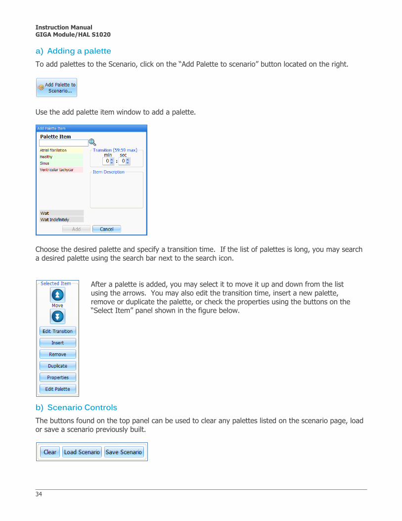
a) Adding a palette To add palettes to the Scenario, click on the “Add Palette to scenario” button located on the right.
Use the add palette item window to add a palette.
Choose the desired palette and specify a transition time. If the list of palettes is long, you may search a desired palette using the search bar next to the search icon.
After a palette is added, you may select it to move it up and down from the list using the arrows. You may also edit the transition time, insert a new palette, remove or duplicate the palette, or check the properties using the buttons on the “Select Item” panel shown in the figure below.
b) Scenario Controls The buttons found on the top panel can be used to clear any palettes listed on the scenario page, load or save a scenario previously built.

Instruction Manual GIGA Module/HAL S1020
35
Scenarios are controlled from the buttons at the bottom of the Scenario page. The same way a music player plays songs, the Scenario plays palette items. Intuitively, the facilitator can play, stop, pause, skip, or repeat items as appropriate. The Scenario Position Indicator points to the current item and shows the current status of the scenario. The following paragraphs describe in detail the behavior of each button and indicator.
The Scenario Position Indicator
The Scenario Buttons
An unfilled triangle means that the scenario is stopped. When the Play button is clicked, the item pointed by the indicator is be played.
A rapidly blinking triangle means that the scenario is playing the item to which the indicator is pointing.
A slowly blinking triangle means that the scenario is paused at the item to which the indicator is pointing.
Plays the item to which the scenario position indicator is pointing. This button has to states: play or pause.
Pauses the scenario. This state of the play button is only active when the scenario is playing. It is disabled when a 'Wait indefinitely' item is playing because in such case the scenario is already paused.
The Stop button has 2 behaviors depending on when it is clicked. When clicked once, the Stop button halts the scenario at the end of the currently playing item. When clicked a second time, the scenario is stopped immediately. For example, if the currently playing item has a transition of 1:00 minute and the Stop button is pressed when it has 0:10 seconds left, the scenario will be halted at the end the transition (i.e., in 10 seconds). If the Stop button is clicked again within those remaining 10 seconds, the scenario stops immediately.
The Next button advances the indicator to the next item on the scenario regardless if the scenario is playing, paused, or stopped. It can also be used to move the indicator to select an item before playing it.
Similar to the Next button, the Previous button returns the indicator to the previous item in the scenario.
The Reset button stops the scenario immediately and returns the indicator to the first item in the scenario.
The Status window displays the name of the current palette being played or the state of the scenario.

Instruction Manual GIGA Module/HAL S1020
36
c) Scenario Automatic-Responses Click on the Scenario Auto- Responses button to configure GIGA Module to advance to the next palette if a shock detected. Scenario automatic responses will respond only while a “wait indefinitely” palette is being played and HAL’s state is a shock-able rhythm.
The three response options are defined below:
Off - The software does not respond to the electric therapy.
Prompt - The software detects the electrical therapy and prompts the user if they would like to advance to the next palette.
Auto – Automatically advance to the next palette.
Navigate to Section III.E.2.b) for information on configuring Non-Scenario Auto Responses

Instruction Manual GIGA Module/HAL S1020
37
Right Panel 6.a) ECG graph The ECG graph displays a real time reading of the ECG lead selected. The virtual monitor is always visible to the facilitator on the right panel.
ECG Options Click on the ECG menu to access the options for the waveform.
Display Properties Click on the display menu to edit the wave form color, amplitude, intensity and scroll direction.
ECG Display Use the color box to change both of the waveforms colors. In addition, the facilitator may modify the amplitude and intensity. These settings apply to both waveforms on the graph.
Traces Scroll Mode Choose the preferred direction of the waveform refresh.
Freeze Click freeze to stop the selected waveform. To unfreeze the selection, click the ECG menu and select Go from the menu.
ECG Beep To enable the ECG beep, select Beep On from the menu. Once the beep is enabled, use the same option to disable.
Time Click on the time option to change the length of the ECG waveform. The options available are 2 seconds, 5 seconds, 7 seconds and 10 seconds.

Instruction Manual GIGA Module/HAL S1020
38
Changing Lead Waveform
To change which lead is displayed on the ECG graph, begin by clicking the ECG icon and selecting close.
Click the waveform menu box and choose the lead that will be displayed.
The new lead information is now displayed.

Instruction Manual GIGA Module/HAL S1020
39
b) Log The Log window allows the facilitator to keep track of every event during a session. It automatically creates a time-stamped entry whenever an event occurs as well as every time there is a change on the patient condition. Also, the facilitator can log observed provider actions with a simple click using the provider evaluation feature. For more information on provider actions logging, navigate to Section III.E.5 Navigate to the right panel and expand the log window by clicking left button.
Every event in a session is recorded as an entry in the Text Log which can be saved at the end of the simulation. The different types of entries are: Actions, Applied Changes, Detected Events, Evaluations, and Notes. Actions Actions refers to those performed by one of the providers in the session. The facilitator can quickly log actions from the Provider Actions section and make the entry more specific using the Team Logging feature. The following is an example of an Action entry: "00:07:24 Action (Assess responsiveness)" Applied Changes An 'Applied' log entry occurs automatically every time there is a change to the physiological condition of the manikin. In other words, every time changes are made from the Details page, Palette page, or from a Scenario a log entry like the following is created: "00:04:01 Applied (00:30): Details: Rhythm Sinus; Cardiac event 0; HR 80;" Detected Events Every time one of the various sensors in the manikin detects a provider action, it is automatically logged as a 'Detected' entry. These actions include electrical therapy (pacing, defibrillation, cardioversion, inappropriate shock). The following example shows an entry after a provider attempts to defibrillate: "00:03:26 Detected (defibrillation): Shock # 2 - 300 Joules." For more information on the individual, team evaluation feature and entering notes, navigate to Section III.E.5

Instruction Manual GIGA Module/HAL S1020
40
D. Bottom Menu The lower panel displays the signal, battery, session time, trending time and power options.
Signal 1.The signal icon is used to monitor the hard wired connection between the laptop and the manikin.
The indicator is clear when no attempts to communicate with the manikin are being made; for example when the module is not connected to the computer or the system is in STAND-BY mode. Full bars indicate excellent communication between the computer and the manikin (i.e., normal operation).
Battery 2.The power status indicator progresses as the internal battery in the manikin is used.
The exclamation mark indicator is shown when there is no communication with the manikin and the program cannot provide the battery information. When the battery is so low that the indicator turns blinking red, the manikin is sent automatically to STAND-BY mode (to protect some of the manikin's internal components) and will not operate until the manikin is reconnected to a power source. Always operate HAL connected to the power outlet supply. The internal battery provides temporary power in the case of outage.
Session Time 3.The session timer allows the facilitator to maintain a time record for individual simulations. The session timer can be reset from the file menu when a new simulation session begins, or by clicking on the session time icon and selecting reset. Please note that log entries are session time dependent.

Instruction Manual GIGA Module/HAL S1020
41
Trending time 4.Trending time controls appear for the Details and Palette tabs, and are hidden when the Scenario tab is chosen. These allow the user to make changes in the manikin’s state and select how long it will be before those changes manifest in HAL’s condition. The range is from immediate change to five minutes in increments.Choose the settings to be changed from the available fields and click one of the “Apply” buttons below. New settings will be applied over the time period indicated by the button's label.
Stand-By 5.It is important to note that HAL uses what is called "soft power," which means that the manikin is activated from the software. It is very important to understand the behavior of the soft power feature, described below. The standby button is located on the bottom right corner of the GIGA Module software.
When the battery is connected, HAL is always in SLEEP mode. HAL will automatically wake up in the ON mode less than 1 minute after starting the software.
The Simulator is currently in Stand-by mode.
The simulator is currently connected and operational.

Instruction Manual GIGA Module/HAL S1020
42
E. Top Menu The GIGA 12 Lead ECG Simulator module has menus which are accessed from the top of the display: File, Setup, and Help. The following sections will explain each menu’s features.
File 1.a) Profile
Opens the Profile dialog box, allowing the user to select between factory-loaded profiles (Default, Quick Start Hal) and user-created profiles. Profiles may be renamed or deleted as well as created from this dialog box. A software restart is not necessary to switch between profiles.
This option allows you to change your current profile. The profile dialog box is displayed:
The profiles dialog box displays the available profiles.

Instruction Manual GIGA Module/HAL S1020
43
b) New Session
Clicking New Session in the file menu will:
Clear any loaded/playing scenario Clear any loaded/playing palette Reset vital signs to normal values Clear out log page Restart the session clock.
The session clock is located at the bottom of the dialog box.
The session time could also be reset by clicking on the timer and selecting reset.
c) Save Report
This option allows you to save all the information recorded in the log page as a text file. Clicking on it brings up the “Save As” dialog box:
Select the desired name and path, and click “Save”.

Instruction Manual GIGA Module/HAL S1020
44
d) Print Report
This option allows you to print a text file containing all the information in the log for the latest session. Clicking on “Print Report” brings up the Print dialog box. The shortcut key for this option is Ctrl + P.
e) Exit
You can exit the software at any time by going to File, Exit or by clicking on the “x” button at the top right corner of the user interface.

Instruction Manual GIGA Module/HAL S1020
45
Set-up 2.a) Options
Module Options only includes one required setting, which is for the manikin’s serial number.
Use the Get Serial Number button to fetch the serial number from the manikin connected.
b) Non-Scenario Auto Responses The GIGA Module software can be configured to respond to electrical therapy by automatically loading a palette when a shock is detected.

Instruction Manual GIGA Module/HAL S1020
46
Auto responses configured from the set-up menu respond to shocks only when a scenario is not in progress. This type of auto response is referred to as a Non-Scenario Automatic Responses.
The three response options are defined below:
Off - The software does not respond to the electric therapy.
Prompt - The software detects the electrical therapy and prompts the user if they would want to change the manikin's vitals to some preset healthy vitals.
Auto - The software automatically detects the electrical therapy and compares it to a threshold selected by the provider, and once this threshold is accomplished the vitals automatically change to a healthy vital state.
Click on the palette button to program a specific palette to be applied after electrical therapy is detected.

Instruction Manual GIGA Module/HAL S1020
47
The “Load Palette Item” dialog box is displayed. Highlight the desired palette and click Load.
The desired palette is now displayed in the “Setting” section.
The Non-scenario automatic response is now configured to automatically load the “Sinus with PJC” palette when a shock of 200 joules or above is detected. You can delete the palette by clicking the “X” button. Deleting the palette defaults the electrical therapy to NSR, 75 bpm, BP 120/80.
Instruction Manual GIGA Module/HAL S1020
48
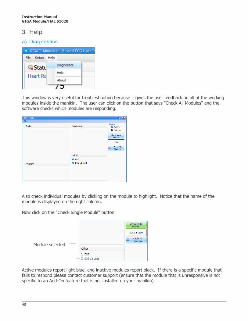
Help 3.a) Diagnostics
This window is very useful for troubleshooting because it gives the user feedback on all of the working modules inside the manikin. The user can click on the button that says "Check All Modules" and the software checks which modules are responding.
Also check individual modules by clicking on the module to highlight. Notice that the name of the module is displayed on the right column. Now click on the "Check Single Module" button:
Module selected
Active modules report light blue, and inactive modules report black. If there is a specific module that fails to respond please contact customer support (ensure that the module that is unresponsive is not specific to an Add-On feature that is not installed on your manikin).
Instruction Manual GIGA Module/HAL S1020
49
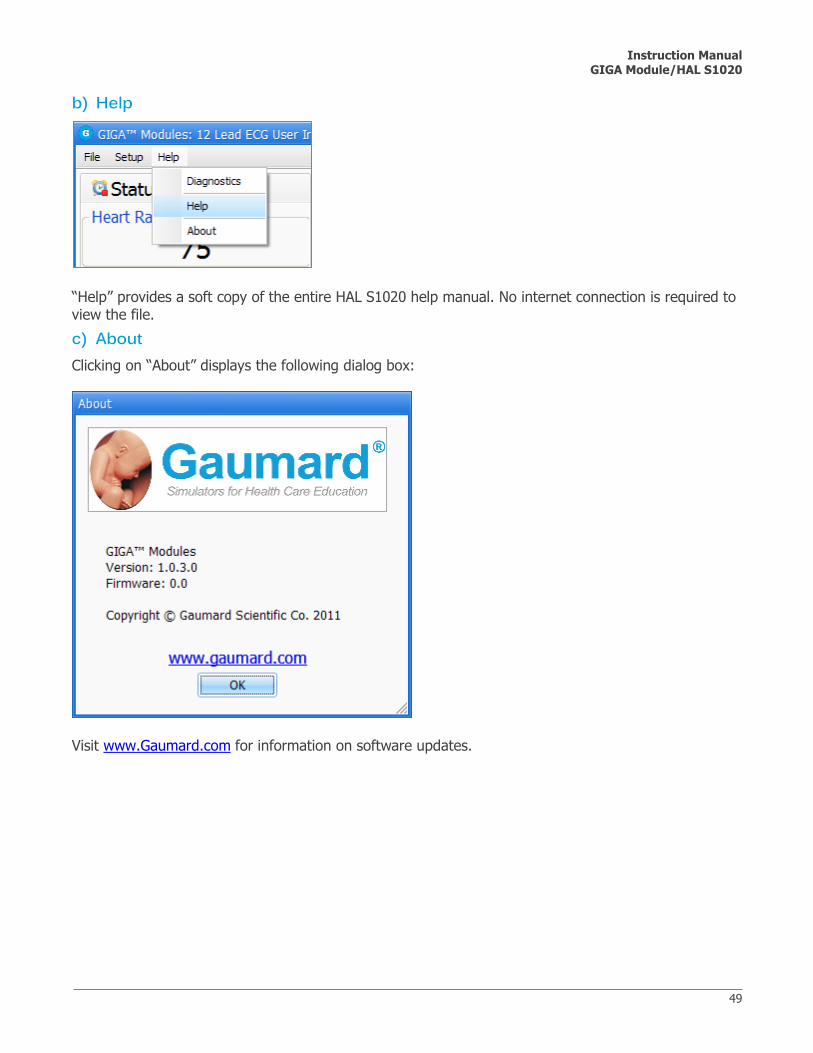
b) Help
“Help” provides a soft copy of the entire HAL S1020 help manual. No internet connection is required to view the file.
c) About Clicking on “About” displays the following dialog box:
Visit www.Gaumard.com for information on software updates.

Instruction Manual GIGA Module/HAL S1020
50
Shock Panel 4.The shock panel is a floating window used for simulating electrical therapy. It can also be used in conjunction with “auto-responses”. To access the shock panel, click on the shock panel button located on the top menu.
Select from a virtual shocks measured in joules or a virtual pacer.
Evaluation 5.The evaluation field is used to track provider actions and rate individual or team performance. All entries made on the evaluation field will be visible in the log panel near the bottom of the page.
Instruction Manual GIGA Module/HAL S1020
51
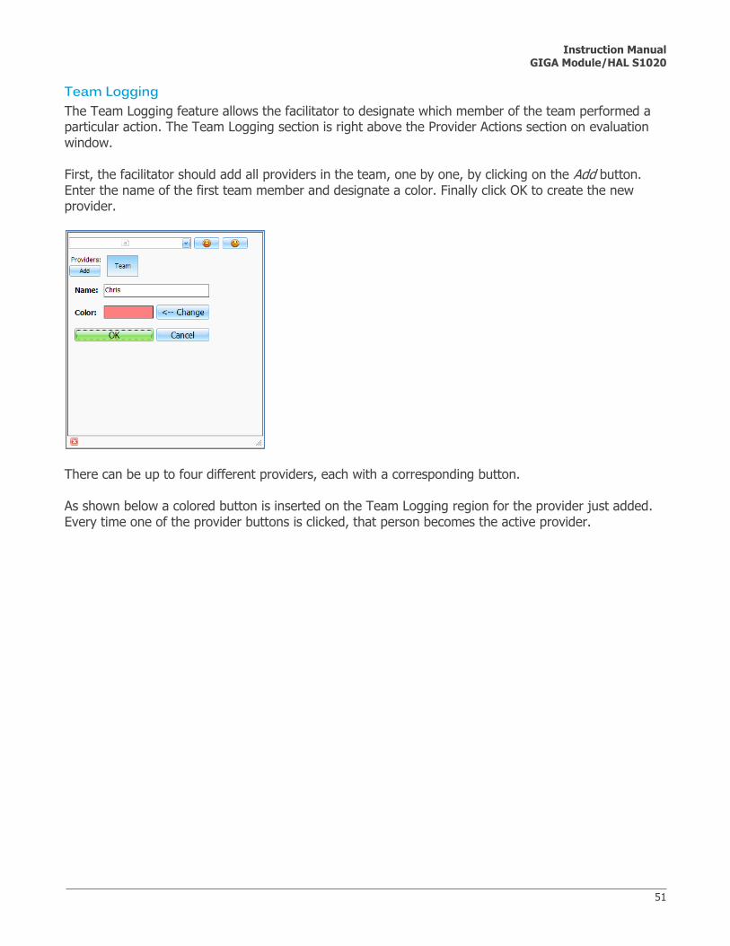
Team Logging The Team Logging feature allows the facilitator to designate which member of the team performed a particular action. The Team Logging section is right above the Provider Actions section on evaluation window. First, the facilitator should add all providers in the team, one by one, by clicking on the Add button. Enter the name of the first team member and designate a color. Finally click OK to create the new provider.
There can be up to four different providers, each with a corresponding button. As shown below a colored button is inserted on the Team Logging region for the provider just added. Every time one of the provider buttons is clicked, that person becomes the active provider.

Instruction Manual GIGA Module/HAL S1020
52
To indicate the active provider, the evaluation bar will display the providers name. While a provider is active, every time a Provider Action is clicked or Evaluation log entry is created it will have the name of the provider prepended to it.
Provider actions The Provider Actions section refers to the collection of buttons in the middle of the window. It allows the facilitator to accurately keep track of provider actions. The buttons are grouped into 3 groups: Basic, , Airway and Breathing. Anytime the facilitator clicks one of the buttons, a time-stamped log entry is generated with that particular action. For example, if the 'Assess responsiveness' button is clicked when the session clock reads 00:07:24, the following entry is automatically generated:
"00:07:24 [Patricia] Action (Assess Responsiveness)" Some provider-action buttons are accompanied by a special option button.The first special button, “ + “, lets the facilitator be a log actions in more detail. For example, if the button “Assess breathing” is clicked, the following entry is created:
"00:01:28 [Patricia] Action (Assess breathing)"

Instruction Manual GIGA Module/HAL S1020
53
On the other hand, if the “ + “ button next to “Assess breathing” is clicked, a list of additional options appears. The facilitator can be more specific and choose, for example, “look, listen, feel”:
...and the following log entry is added:
"00:01:28 [Patricia] Action (Ventilate): look, listen, feel"
Evaluation The Evaluation feature allows the facilitator to insert standard evaluations or arbitrary notes into the log.
Standard evaluations are given context by their position in the log relative to detected and observed provider actions. To add entries for specific providers, select the active provider and type the note in the entry field. After clicking OK, the following entry is shown in the log panel.
"00:07:41 [Patricia] Note: provider took too long to assess patient "
To deactivate, deselect the active provider and return to general logging, click the “Team”.
Grading Each provider can also be graded using the satisfactory and unsatisfactory buttons. The satisfactory entry is show below:
"00:07:41 [Patricia] Evaluation (Care Provided) : Satisfactory” For information on saving the log report, navigate to Section III.E.1.c)

Instruction Manual GIGA Module/HAL S1020
54
IV. Care and Cautions

Instruction Manual GIGA Module/HAL S1020
55
A. Overall Warnings Remember that damage caused by misuse is not covered by your warranty. It is critical to understand and comply with the following guidelines:
Cleaning HAL should be cleaned with a cloth dampened with diluted liquid dishwashing soap. If medical adhesives remain on the skin, clean with alcohol wipes. DO NOT USE “GOO GONE” as the citric acid in the formula will cause pitting of the various materials comprising your manikin.
Storage Store HAL in a cool, dry place. Extended storage above 85 degrees Fahrenheit (29 Celsius) will cause the manikin to soften and slowly warp. It is acceptable to operate HAL at an ambient temperature of 95 degrees Fahrenheit (35 Celsius). HAL is "splash-proof" but not water-proof. Do not submerge or allow a large volume of fluid to enter the interior of the manikin. Do not expose the computer to water or excessive dust.
Set Up When connecting the battery to the manikin, make sure to match the two color-coded connectors to the corresponding color-coded battery terminals. NEVER disconnect the communications module while the HALUI software is running. The software will halt, and the module may be damaged.
B. Electrical therapy Defibrillation is only allowed on the large sternum and apex sites, circled RED below. NEVER deliver a shock to ECG electrode targets on the shoulders or waist, marked BLUE below. Doing so will not create a fire hazard, nor is there risk of shock to the provider, but internal damage in HAL may result. This situation is considered improper use and is NOT covered by the HAL warranty. The system will require repair at our facility.
Instruction Manual GIGA Module/HAL S1020
56
There are inherent dangers in the use of some medical devices. For simulations that incorporate electrical therapy of any kind, always know your equipment, and follow the device manufacturers' safety guidelines. ECG and electrical therapy checklist and warnings:
Only deliver electrical therapy when the simulator is fully assembled, dry, and undamaged. Make sure the defibrillation patches on the simulator are in good condition, including removing
any and all gel residue on the defibrillation patches from previous use(s). It is a good practice to remove gel residues after every use. Failure to do so will leave behind a film of electrode gel that hardens causing arcing and pitting.
Do not re-use the gel-adhesive pads. Do not leave them on for next day use.
Use hard paddles or wet-gel pads preferably. Avoid using solid-gel pads since they present higher risk of burning the simulator’s skin.
Gel pads have a shelf life. Make sure they are not expired to avoid arcing.
Make sure the simulator is not in contact with any electrically conductive surfaces.
Use the simulator only in a well-ventilated area, free of all flammable gases.
NEVER attempt to service or modify any of the electrical connections, especially those between conductive skin sites and the internal electronics. Discontinue use if any wires are found exposed with damaged insulation.
Real medical products, especially electrodes, sometimes use powerful adhesives that can be difficult to remove. A gentle, degreasing cleanser may be needed. Refer to Care and Cautions for more information.
Electrode gel on the skin between any two electrode targets can become a pathway for
electrical current, just as in real life. If this occurs, HAL's skin can be burned.
Do not allow defibrillation pads to overlap ECG sites. Doing so will may damage the simulator and cause arcing.
Should dark traces appear on the conductive patches due to gel residue or previous arcing, use a pencil eraser to remove the traces and then clean with alcohol.
DO NOT SCRATCH the conductive patches with abrasive objects; doing so will cause irreversible damage to the conductive sites and subsequently cause arcing.

Instruction Manual GIGA Module/HAL S1020
57
V. Appendix

Instruction Manual GIGA Module/HAL S1020
58
A. More about Scenarios Tips on Creating Scenarios Thinking in Terms of Palette Items As described previously, Palette items represent complete or partial groups of settings that have been stored as a single item. We learned how applying partial states will hold constant all settings that are left unspecified. Not only does it take time to customize the palette, but a very large palette becomes difficult to navigate. So, it is desirable to minimize the number of Palette Items in each Profile. To accomplish this, an experienced facilitator tries to create items that are as generally applicable as possible and can, thus, be applied to a wide range of scenarios. The key is to only include in your Palette Items the settings that are directly related to the physiological event represented by that Palette Item. Smart Scenarios After reading the Details, Palette, and Scenarios sections of this guide, it should be clear how to build a scenario. You may have already tried building your own or modifying some of the factory presets. The following four guidelines will refine your ability to build the best possible scenarios. 1. How will the scenario begin? The first thing to consider is the initial condition of the patient. Create a Palette Item to describe this condition. Make sure that this first step in the scenario is a complete state. That is, indicate some selection for each and every available setting on the Details page. Remember that only the settings you specify will cause a change in HAL, and all other settings will remain constant. So, by starting with a complete state, HAL's condition will always be the same when the scenario starts, regardless of what he was doing previously. Likewise, the "transition duration" of the first step in the scenario should be zero, indicating that changes are applied immediately. There is one point that can cause confusion and warrants further explanation. It is an extension of the above discussion of partial states. The issue is best illustrated through the following example:
Suppose that you are creating a Palette Item to start your scenario. In this case, you have decided that the patient will be apneic. The question is, "How should the lung sounds be set?" Most people's first inclination is to set the lung sounds to "none." This is incorrect, despite apnea. Obviously, no lung sounds should be heard during apnea, but since you have already set respiratory rate to zero, none will be. (Sounds are synchronized to the breathing cycle.) What you are really setting here when you choose a lung sound is the condition of the lungs, given respiratory drive. That is, if the patient's respiratory rate were changed from zero, what sound would be heard? Assuming that the lungs themselves are normal in this scenario, you would choose "normal" for the lung sound setting.
Instruction Manual GIGA Module/HAL S1020
59
Then, as the scenario progresses, if the patient starts breathing, there will be no need to set the lung sound again. It will already be set. The same principle applies to the heart sound and other settings.
2. Include notes to guide the facilitator during the simulation. It is common for scenario designers, especially those who act as facilitators, to neglect the importance of notes in the scenario. They think that they will remember the learning objectives, patient history, and other details at the time they are ready to conduct the simulation. They usually don't, especially when revisiting a scenario months after creating it. When you add "Wait" and "Wait Indefinitely" steps to a scenario, you have an opportunity to edit the item description. Use this description field to hold notes to the facilitator. Typically, scenario designers write notes in that space to indicate what the provider(s) or facilitator should be doing at that point. Further, when saving the scenario, you may edit the scenario description. This is the best place to put patient history and any other longer notes and instructions. 3. Assume that providers will do the right thing. Usually, you should create a scenario with the assumption that the providers will perform correctly. As long as they do, the scenario can simply be allowed to continue. Naturally, you must be prepared for what might happen to HAL when providers deviate from expecta-tions. The consequences of such deviations can sometimes be included in the scenario, punctuated by "Wait Indefinitely" items. In other cases, the simulation will require more direct control by the facilitator via either the Palette or Details page.

Instruction Manual GIGA Module/HAL S1020
60
B. File Structure Advanced users may find it helpful to understand the GaumardUI directory structure. With direct file manipulation, one can easily move palette items and scenarios between profiles, as well as move entire profiles from one computer to another.
Profiles
In the GUI program folder is the “profiles” sub-folder (e.g. “C:\Program Files\Gaumard Scientific\GIGA Module\profiles”). All user information is saved there, and it is the only folder that should be modified manually. In the example shown, notice that there are two profiles in this installation, “Default Profile”, and “Quick Start Scenarios”.
Palette Items
Saved as “*.plt” files, palette items in each profile are located at the top-level of each profile folder. To copy palette items from one profile to another, simply copy the .plt file found in the source profile folder.
Scenarios
Scenarios are stored as sub-folders within profile directories. Scenarios can also be transferred between profiles by copying the scenario folder and its contents. Never… modify files in the “resources” directory or those at the top-level of the “Gaumard User Interface”
directory.
manipulate files or folders while the GaumardUI software is running. Modify or delete “*.dll”, “*.scn”, or “*.sys” files.

Instruction Manual GIGA Module/HAL S1020
61
C. Troubleshooting General Troubleshooting Guide Use the following table to find causes and solutions to a number of possible problems.
Symptom Possible Cause Solution
Communication never gets established or is
lost (blinking communi-
cation indicator is
consistently red)
Data cable is not connected.
USB Module is not connected.
Verify connection of the Ethernet cable and USB module to the
computers USB port.
D. Warranty EXCLUSIVE ONE-YEAR LIMITED WARRANTY Gaumard warrants that if the accompanying Gaumard product proves to be defective in material or workmanship within one year from the date on which the product is shipped from Gaumard to the customer, Gaumard will, at Gaumard’s option, repair or replace the Gaumard product.
This limited warranty covers all defects in material and workmanship in the Gaumard product, except:
1. Damage resulting from accident, misuse, abuse, neglect, or unintended use of the Gaumard product;
2. Damage resulting from failure to properly maintain the Gaumard product in accordance with Gaumard product instructions, including failure to property clean the Gaumard product; and
3. Damage resulting from a repair or attempted repair of the Gaumard product by anyone other than Gaumard or a Gaumard representative.
This one-year limited warranty is the sole and exclusive warranty provided by Gaumard for the accompanying Gaumard product, and Gaumard hereby explicitly disclaims the implied warranties of merchantability, satisfactory quality, and fitness for a particular purpose. Except for the limited obligations specifically set forth in this one-year limited warranty, Gaumard will not be liable for any direct, indirect, special, incidental, or consequential damages, whether based on contract, tort, or any other legal theory regardless of whether Gaumard has been advised of the possibilities of such damages. Some jurisdictions do not allow disclaimers of implied warranties or the exclusion or limitation of consequential damages, so the above disclaimers and exclusions may not apply and the first purchaser may have other legal rights.
This limited warranty applies only to the first purchaser of the product and is not transferable. Any subsequent purchasers or users of the product acquire the product “as is” and this limited warranty does not apply.

Instruction Manual GIGA Module/HAL S1020
62
This limited warranty applies only to the products manufactured and produced by Gaumard. This limited warranty does not apply to any products provided along with the Gaumard product that are manufactured by third-parties. For example, third-party products such as computers (desktop, laptop, tablet, or handheld) and monitors (standard or touch-screen) are not covered by this limited warranty. Gaumard does not provide any warranty, express or implied, with respect to any third-party products. Defects in third-party products are covered exclusively by the warranty, if any, provided by the third-party.
Any waiver or amendment of this warranty must be in writing and signed by an officer of Gaumard.
In the event of a perceived defect in material or workmanship of the Gaumard product, the first purchaser must:
1. Contact Gaumard and request authorization to return the Gaumard product. Do NOT return the Gaumard product to Gaumard without prior authorization.
2. Upon receiving authorization from Gaumard, send the Gaumard product along with copies of (1) the original bill of sale or receipt and (2) this limited warranty document to Gaumard at 14700 SW 136 Street, Miami, FL, 33196-5691 USA.
3. If the necessary repairs to the Gaumard product are covered by this limited warranty, then the first purchaser will pay only the incidental expenses associated with the repair, including any shipping, handling, and related costs for sending the product to Gaumard and for sending the product back to the first purchaser. However, if the repairs are not covered by this limited warranty, then the first purchaser will be liable for all repair costs in addition to costs of shipping and handling.
Extended Warranty In addition to the standard one year of coverage, the following support plans are available:
Two-Year Extension (covers second and third years) Call for pricing (USA only)

Instruction Manual GIGA Module/HAL S1020
63
E. Contact Us If you have read this user's guide and still require assistance, it's easy to reach us. E-mail Technical Support: [email protected] E-mail Sales and Customer Service: [email protected] Phone: Toll-free in the USA: (800) 882-6655 Worldwide: 01 (305) 971-3790 Note: Before contacting Tech Support you must:
1. Have the manikin’s Serial Number (located in the left leg under the IM site) 2. Be next to the simulator if troubleshooting is needed.
Fax: (305) 667-6085 Post: Gaumard Scientific 14700 SW 136 Street Miami, FL 33196-5691 USA Office hours: Monday-Friday, 8:30am - 4:30pm EST (GMT-5, -4 Summer Time) Gaumard®, HAL® and GIGATM are trademarks of Gaumard Scientific Company, Inc. ©Gaumard Scientific Company, 2011. All rights reserved. Patented; other patents pending