12-bit digital-analog converter - duke electrical and...
TRANSCRIPT

12-bit Digital-Analog Converter
ECE262 Analog Circuit Design
Team MemberTeam MemberTeam MemberTeam Member
Chao ChenChao ChenChao ChenChao ChenJae Jae Jae Jae ShikShikShikShik LimLimLimLim LingzhaoLingzhaoLingzhaoLingzhao XieXieXieXie

Agenda
Abstract
Background
Block Diagram
Module Level Design
System Level Design
Design Review
2

Abstract
Design of a 12-bit Digital-Analog Converter with mixed-signal design
The lower 8 bits of digital-analog conversion are implemented by R-2R Ladder while the upper 4 bits are implemented by Binary-to-Thermometer Decoder
Carefully design the Op-Amp to optimize the performance of the DAC
3

BackgroundBinary-to-Thermometer Decoder
R-2R ladder requires significantly high precision
resistors and is usually limited to a max of 8-bit
resolution.
The implementation of Thermometer Decoderallows for a 12-bit resolution while only needing
the accuracy of a 8-bit DAC
N inputs thermometer decoder has 2n−1 outputs.
Each output corresponds to a base 10 value of the
possible binary inputs.
4

Background Example of 3bits Binary-to-Thermometer Decoder
5
Three bits input and corresponding seven outputs

Background R-2R Ladder with Thermometer Decoder
R Array
R-2R Ladder
4 bits
Thermometer
Decoder
6

OpampAnalogoutputAnalog
Low Pass Filter
Thermometer
Decoder
4-bit
+R-2R
Ladder
15-bit
LSB
MSB
R Array
8-bit
7
Block Diagram

Module Design
8

R-2R Ladder and R Array Module
Opamp
Low Pass Filter
Thermometer
Decoder
R-2R Ladder
R Array
9

10
R-2R Ladder (8bits)
Schematic

11
R-2R Ladder (8bits)
Simulation using Hspice (Inputs)

12
R-2R Ladder (8bits)
Simulation using Hspice (Output)

13
R-2R Ladder and R Array Module
Layout (Both LVS and DRC clean)

4bits Thermometer Decoder Module
Opamp
Low Pass Filter
Thermometer
Decoder
R-2R Ladder
R Array
14

15 bits output to R Array 15
4bits Thermometer Decoder Module Schematic

R Array
R-2R Ladder
Thermometer
Decoder
16
4bits Thermometer Decoder Module Schematic

17
4bits Thermometer Decoder Module Simulation using Eldo (12bits input)
Inputs for the thermometer decoder and R-2R array

18
4bits Thermometer Decoder Module Simulation using Eldo (output)
Output of the thermometer decoder and R-2R array

3.29422
3.29290
Resolution=1.3mV
19
4bits Thermometer Decoder Module Simulation using Eldo (magnified output)

4 input NAND 3 input NAND4 input NOR 3 input NOR
20
4bits Thermometer Decoder Module Layout for MOS Gates

2 input NAND 2 input NOR
21
4bits Thermometer Decoder Module
Layout for MOS Gates

22
4bits Thermometer Decoder Module
Layout (Both DRC and LVS Clean)

OP Amplifier Module
Opamp
Low Pass Filter
Thermometer
Decoder
R-2R Ladder
R Array
23

24
OP Amplifier Module
Schematic

Linear through the whole range Input range: 0.575V ~ 4.807V DC Gain: 72.775 dB Phase Margin: 81.865 degrees Unity Gain Bandwidth: 28 MHz Slew rate: 8.4V/us
25
OP Amplifier Module
Specification

R, R-2R
Output
OPAMP
Output
26
OP Amplifier Module
Simulation using Eldo

1.3mV
27
OP Amplifier Module
Simulation using Eldo

28
OP Amplifier Module
Layout (Both DRC and LVS Clean)

29
OP Amplifier Module
Layout (General View)

Tail bias Out bias30
OP Amplifier Module
Layout (Details)

P Load P Out
31
OP Amplifier Module
Layout (Details)

Common
Centroid
Differential
Pair
32
OP Amplifier Module
Layout (Details)

Low Pass Filter Module
Opamp
Low Pass Filter
Thermometer
Decoder
R-2R Ladder
R Array
33

34
Active Low Pass Filter
Schematic
Second-order unity-gain Tschebyscheff LPF

35
Active Low Pass Filter
Simulation - Hspice
Cut off frequency: 27.24MHz
36
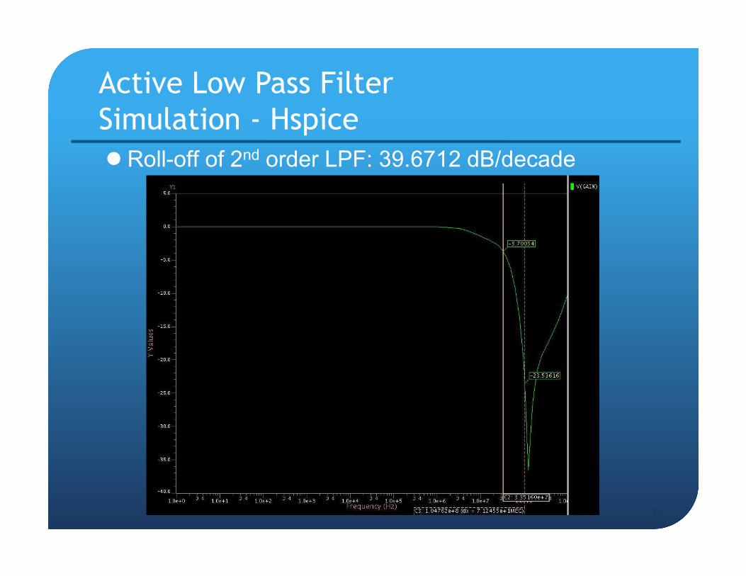
Active Low Pass Filter
Simulation - Hspice
Roll-off of 2nd order LPF: 39.6712 dB/decade

37
Active Low Pass Filter
Layout OPAmp
5k Ω
2ea
22pF
0.3pF

System Design
38

12-bit Digital-Analog Converter Top Level Schematic
39
Thermometer
Decoder +
R Array
Dummy
R and C
Source Follower
ActiveFilter
Analog
VDD
Analog
GND

R, R-2R
Output
OPAMP
Output
LPF
Output
40
12-bit Digital-Analog Converter Top level simulation using Eldo

41
12-bit Digital-Analog Converter Layout (Both DRC and LVS Clean)

42
12-bit Digital-Analog Converter All module layout
Thermometer
Decoder
(Digital)
R Array
(Analog)
OP Amp &
LPF
(Analog)

43
12-bit Digital-Analog Converter Layout – Guard Rings
Digital Logic
Analog Circuit
P+
(GND)
N well, N+
(GND)
P+
(A Gnd)
N well, N+
(A Vdd)

44
12-bit Digital-Analog Converter Simulation using Eldo (Max. at 14MHz)
Stable state exist, operate well at 14MHz
OPAMP
Output
R, R-2R
Output

Input bits: 12-bit
Input voltage: 5V
Output range: 0.58V ~ 4.80V
Resolution: 1.3mV
Bandwidth: 14MHz
45
Design ReviewSpecification

R and R-2R Array9 resistors with resistance 2R (=2*20 kΩ)22 resistors with resistance R (=20 kΩ)
Thermometer Decoder2 Input NAND: 8 ea 3 Input NAND: 3 ea 4 Input NAND: 1 ea2 Input NOR: 8 ea 3 Input NOR: 3 ea 4 Input NOR: 1 eaInverter: 15 ea
OP-AMPNmos: 5, Pmos: 4, C: 5pF*1
2nd order Low Pass Filter
OP-AMP Capacitor: 0.3 pF, 22pF Resistor: 5 kΩ * 2
46
Design ReviewComponent used

Total power consumption (from Eldo)
P_system=1.5647mW
Total Area: 1.4453 mm2
1077um * 1342 um = 1.4453 mm2
47
Design ReviewPower consumption & Area used

In order to improve the non linearity of analog output, we have calibrated the resistor values connected to output of the thermometer decoder
The waveform on the next slide shows that the output of resistor array has almost linear output
48
Design ReviewOutput calibration

49
Design ReviewOutput calibration – simulation (Eldo)