12-5 latest technology advancements in hydraulic systems
TRANSCRIPT

Latest Technology Advancements in Hydraulic Systems for Refuse Vehicle Applications: The Case of an Automated Side Loader
Dr. Gabriele Altare, Dr. Germano Franzoni, Jarmo Harsia, Thomas Hickey Parker Hannifin Corp. – Global Mobile Systems, 850 Arthur Ave, 60007 Elk Grove Village, IL, USA, email: [email protected], [email protected]
Abstract The present paper describes an innovative electro-hydraulic system developed for
automated side loaders. The system is based on Intelligent Flow Control (IFC), a concept
where open circuit electric displacement controlled pumps are coupled with EH directional
control valves. IFC was selected in order to achieve the level of performance required, in
terms of efficiency and productivity (i.e. cycle times), and also to provide the best possible
control of the side loader arm. The paper describes the system layout and the basics of the
controls: from the alghorithms of the arm actuators to the vehicle on board telemetry and
diagnostic. The paper reports the comparison between the IFC system (implemented on the
vehicle) and a more traditional approach based on a Load Sense Flow Sharing concept. The
benefits of the IFC solution are highlighted focusing on the energy efficiency (very important
especially in the case of CNG engines, where the torque available at idle is significantly
lower than diesel engines), but also in terms of controlability and response (due to the lack
of load sensing signal lines).
KEYWORDS: Automated Side Loader, Intelligent Flow Control, Fuel Efficiency,
Productivity, Simplicity, Cost effectiveness
1. Introduction The use of automated side loaders is becoming more and more popular for refuse collection
in most of residential areas of the US. In fact, these machines are capable of loading
garbage cans automatically, without the need of operators on the ground moving or handling
the cans (which happens in the case of rear loaders). The collection of cans happens
through an arm, equipped with a grabber. Once approached the can, the driver extends the
arm until reaching the can, the grabber closes and the can is then lifted and dumped in the
Group 12 - Special Applications | Paper 12-5 351

hopper. Afterwards, the empty can is returned on the ground. The truck hopper is also
equipped with a packer compressing the loaded garbage. The arm and the packer control
are realized through a hydraulic system, which is capable of realizing more than a thousand
cycles per day; in fact an average can pick and dump cycle lasts approx. 10 seconds or less.
From a technical stand point, automated side loaders are very complex vehicles: beside the
electro-hydraulic system, they are for example equipped with cameras, GPS, weight
sensors. The arm design and hydraulic control are the key of the machine, being the element
responsible the effectiveness and performance of the machine. Typical automated side
loader arms have limited degrees of freedom because they are characterized by geometrical
constraints. These can be a horizontal extension, a vertical lift on a rail or a parallel arm
linkage: they make the control of the arm easier, but limits the performance of the arm. For
example, can picks below grade are not possible or also the dump trajectory is fixed, and
cannot be adapted to external obstacles, such as a tree or a power line.
Figure 1: The side loader object of the resent study
The Parker GMS engineering team was challenged to develop an electro-hydraulic system
for a new side loader equipped with an innovative arm concept (Figure 1). This arm is
characterized by no geometrical constrain in the X-Y plane and the function synchronization
and control is purely achieved through the hydraulic system, based on the actuators’ position
feedback.
352 10th International Fluid Power Conference | Dresden 2016

The arm control had to be capable of:
Moving following the trajectory imposed by the operator joystick, as well of achieving
different possible trajectories when executing the can dump.
Automating the dump cycle returning the empty can in the same exact location it was
picked
Achieving cycle times below 7 sec minimizing the shake of the vehicle cab.
Maximizing the energy efficiency, making it possible to run a full cycle even on CNG
powered trucks at low idle.
Estimating the can weight (thus the truck estimated load) and realizing a slower
dump cycle for heavier cans.
Providing real-time system diagnostics broadcasted via an on-board modem.
Being simple and cost effective.
2. System architectures comparison Historically, in the last decades, the development of hydraulic systems has been
characterized by a constantly increasing degree of intelligence and automation. However,
this development has mostly involved the directional elements and the control valves,
leaving the pumps to a lower technology stage. Even in electro-hydraulic load sensing (LS)
systems, which represent the finest current technology, the variable displacement pump is
controlled by a hydro-mechanical compensator, which is controlled by the pressure signals
coming from the valves. Left of Figure 2 represents a simplified layout and operation of a
traditional LS system with a variable pump: when the operator commands a function, the
command first reaches valve spool; the valve shifts accordingly, detecting the load
pressures and communicating the highest load to the pump through the LS line. The pump
control then adjusts the displacement in order to set the pump delivery pressure as:
(1)
where is the load sensing pressure and is the margin pressure. This allows the flow to
reach the actuator, which finally moves. The advantages of the LS system compared to
other predecessor is the controllability intended as the independence of the actuator speed
as a function of the load, at least in most of the condition. Flow-sharing solution came out in
order to solve controllability in event of saturation as described in /1/ and /2/.
Group 12 - Special Applications | Paper 12-5 353
In the past years, the Parker Global Mobile Systems team has focused on the research and
development of new hydraulic systems. These researches culminated with the Intelligent
Flow Control (/3/), an architecture based on open circuit electric displacement controlled
pumps (EDC) and directional control valves.
The IFC system concept allows introducing a new level of intelligence in the system
improving the performance of mobile equipment. The use of the IFC also introduces new
degrees of freedom in the system design and therefore the possibility of simplifying the parts
of the system without penalizing the performance level.
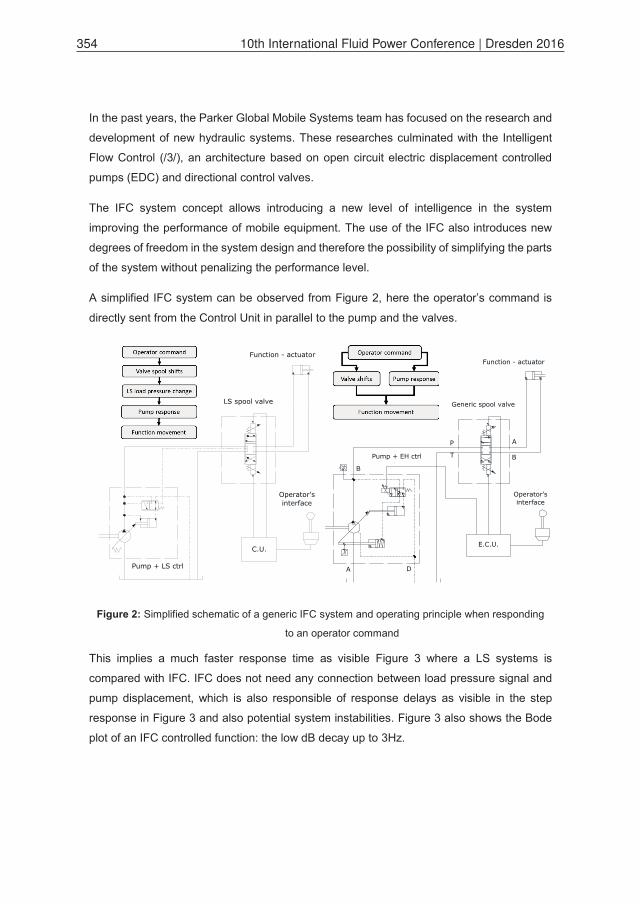
A simplified IFC system can be observed from Figure 2, here the operator’s command is
directly sent from the Control Unit in parallel to the pump and the valves.
Figure 2: Simplified schematic of a generic IFC system and operating principle when responding
to an operator command
This implies a much faster response time as visible Figure 3 where a LS systems is
compared with IFC. IFC does not need any connection between load pressure signal and
pump displacement, which is also responsible of response delays as visible in the step
response in Figure 3 and also potential system instabilities. Figure 3 also shows the Bode
plot of an IFC controlled function: the low dB decay up to 3Hz.
Operator'sinterface
C.U.
Function - actuator
LS spool valve
Pump + LS ctrl
Operator'sinterface
E.C.U.
Pump + EH ctrl
Function - actuator
Generic spool valve
A
B
P
T
x
p B
A D
354 10th International Fluid Power Conference | Dresden 2016

Having a stable and controllable system allows simplifying the spools design and reducing
meter out restrictions that are usually introduced in order to dampen the functions and make
them more stable. Moreover the use of electronics in order to control the pumps allows better
power management. In fact the engine CAN bus information (such as engine load and
engine speed) can be matched with the pump controls in order to maximize the power output
at every engine condition. All these benefits result in significant productivity improvements.
Figure 3: Response comparison between IFC and LS for two fork lift systems (left), Bode
diagram for IFC controlled actuator.
2.1. Hydraulic Schematic With reference to Figure 1 and looking at the arm operation, only three of the functions need
to be controlled simultaneously. In addition, the requirement (by law) of actuator mounted
counterbalance valves implies that the spools may not need to work as meter-out control
elements. By combining these considerations with the IFC design concept, it is possible to
adapt a triple IFC pump and simple ON-OFF valves architecture (Figure 4) for achieving a
very precise control of the arm and eliminating any metering loss. The control of the
function’s flow is managed by the pumps (P1 – grabber/extension, P2 – lift, P3 - rotation),
while the valves are just used for directional control. Between the pumps and the “arm
manifold”, the three flows pass through a “combiner manifold” with three check valves and
an “isolation valve”. When the packer is activated, the flow of all three pumps is combined
to the packer valve. It is also noticeable that the extension function runs in regenerative
mode thanks to the check and pilot-to-close check valves in the counterbalance block. The
body functions are controlled by a 3 section valve. When these are activated, only the flow
of the smaller pump P3 is used, while P1 and P2 are left at standby.
Group 12 - Special Applications | Paper 12-5 355

Figure 4: Schematic of the IFC system for the automated side loader.
356 10th International Fluid Power Conference | Dresden 2016

The body functions are never run simultaneously with the arm. Normally, also the packer
function runs stand alone, but some particular cases might require packing while the arm is
being moved. In these cases the isolation valve in the combiner manifold is actuated, so that
P1 and P2 are used for the arm, while P3 keeps moving the packer at a reduced speed.
3. The Control Concept Electronics is heavily used in this system. In particular, the position feedback information of
the arm functions is the key for meeting the required specifications. The system comprises
of three Parker Intellinders, used for the lift, extension and slide functions. In this particular
case the Intellinder has a unique advantage, allowing the use of small rod and bore
diameters, compared to other traditional solutions (magnetostrictive sensors, which use
would increase cylinder sizes resulting in larger pumps and valves). Figure 5 shows the
control logic of the system that is implemented using IQAN modules. The MD4 and XA2
includes the control logic of the valves, reads the sensors and Intellinders, interfaces with
the operator’s commands and communicates with engine and transmission. The MC2 works
at a higher processing frequency and it is dedicated just to the pumps, implementing both
displacement and pressure control. The MD4 communicates to the MC2 via CANbus the
desired pump displacement for each of the three units and the MC2 drives the pumps
accordingly based on displacement and pressure feedback. Both modules are connected to
a G3 modem for remote diagnostics allowing the operation centre of the fleet management
to understand real-time which are the problems on the truck and therefore send the proper
assistance in case of failure.
The other important part of the system is the control concept implemented in order to achieve
the desired motion of the arm. Figure 6 represents the control concept architecture: the
operator’s input (whether is a coordinated motion or an automated cycle) enters the inverse
kinematics model of the arm. This block translates the inputs into current commands to the
valves and the pumps. As said, the valve command is on/off type, while the metering is
realized in the pumps. The amount of flow delivered by each pump allows following the
desired motion paths.
Group 12 - Special Applications | Paper 12-5 357

Figure 5: Control logic of schematic of the Parker IFC system
The pump commands generated by the inverse kinematics block consist of the Feed
Forward portion (marked as FF in the figure), which is added to the closed loop PID control
output, in order to achieve a high level of precision and compensate for the dynamic motion
effects (e.g. some functions accelerate faster than others). The PID block reads the
difference between the actual position feedback readings and the target position (also
generated by the kinematics model).
Figure 6: Simplified representation of the control concept layout.
358 10th International Fluid Power Conference | Dresden 2016
From the control point of view, the direct control of the pump and the displacement feedback
information allows a very accurate control of the flow delivery. Therefore, known the cylinder
bore and rod sizes, the system can deliver the right amount of oil to move each function to
the desired target in the desired amount of time. Vice-versa, a system that meters the flow
across valve spools cannot have exact information about the flow delivery.
3.1. Inverse kinematics model The inverse kinematic model allows to use of FF control and to maintain a straight trajectory
of the arm during the picking operation. In order to accomplish this objective it is necessary
to correlate the command of the operator to the speed of the actuator and to the flow rate
generated by the pumps.
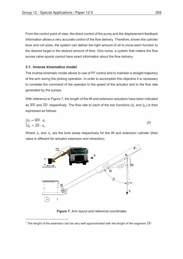
With reference to Figure 7, the length of the lift and extension actuators have been indicated
as and respectively. The flow rate to each of the two functions ( and is then
expressed as follows:
(2)
Where and are the bore areas respectively for the lift and extension cylinder (their
value is different for actuator extension and retraction).
Figure 7: Arm layout and reference coordinates
1 The lenght of the extension can be very well approximated with the lenght of the segment
Group 12 - Special Applications | Paper 12-5 359

Point B is representative of the position of the grabber and can be expressed, as:
(3)
With and . Being the position of the can, the x
and y components of the speed of the can, expressed as a function of cylinder speeds are:
(4)
Keeping in mind that: , and , the horizontal
and vertical speed of point B are:
(5)
By grouping the actuators’ speed is therefore:
(6)
In order to move the arm horizontally, then , therefore:
(7)
If the operator wants to run the arm vertically, then , therefore:
(8)
If the control wants to keep a straight line, then , where is a constant value,
therefore:
(9)
360 10th International Fluid Power Conference | Dresden 2016

It is important to remind that the value of is proportional to the x axis joystick, while is
connected to the y joystick position. In other words Eq. (6,7,8,9) express the relationship
between the pump flow rate, actuator speed and joystick command through the inverse
kinematic model. The same consideration can be done for the retraction and lowering by
considering the rod side area of the actuators.
4. Performance comparison with LS system The IFC system has been compared to an alternative more conventional solution, based on
a single pump Load Sensing flow sharing approach, which schematic is shown in Figure 8.
Figure 8: LS system for side loader
Group 12 - Special Applications | Paper 12-5 361

In order to perform a correct energy analysis, the following duty cycle has been considered:
1. The truck reaches a complete stop; the operator extends the arm following a
horizontal straight line until he reaches the can. An average situation of a 6ft pickup
(distance from the chassis) has been considered.
2. The operator performs the automated cycle: the can is grabbed and lift and extension
are operated following a straight line connecting the grab point to the dump point.
Rotation is activated and the garbage is dumped in the truck. Afterwards, rotation,
lift and extension are run simultaneously and the can is returned to the initial position
following a straight line path. The grabber is opened and the can is released.
3. The arm is then stowed in the transport position using the “auto stowe” function.
This cycle has been performed with the real truck and the system data were acquired
(positions, flows and pressures). By analysing the pumps pressure it is noticeable how the
three functions operate at significantly different pressure levels, in particular during the lift
phase, the extension function is at very high pressure, when the can is dumped, rotation has
the highest pressure and during the return, extension is at high pressure (regen function)
while lift is at very low pressure. The data recorded were used as input for the LS model
within AMESim, where measured pump pressures were used as load pressures (lift, extend,
etc.), while the margin pressure and the compensator losses were calculated by the model.
The losses in the hydraulic units were estimated based on the pump efficiencies lookup
tables. Figure 9 shows a summary of power demand and the energy consumed by the two
systems during a single cycle. From the power curves it is possible to observe how the
instantaneous power consumption of the IFC system is always below the LS system. The
energy chart shows instead how the energy consumption develops along the cycle time. In
particular, it is possible to notice how the IFC system requires (at the engine shaft) 102 kWs
to complete the cycle. Instead the LS system requires 137 kWs to complete the same
operation. Therefore the energy consumed by the IFC system is 26% lower than the LS
system. Figure 9 shows also the contribution of the different losses in the LS system: the
compensator losses and the margin pressure losses. In the cycle 23 kWs are wasted on the
compensators and 12 kWs are wasted due to the margin pressure.
362 10th International Fluid Power Conference | Dresden 2016

Figure 9: Power demand (left) and Energy consumption (right) during the automated cycle for
the IFC and LS system
Side loaders execute between 1000 and 1500 pick-ups per day, the amount of energy saved
per pick-up is 35 kWs, which correspond to 9.7 kWh per day in the case of 1000 operations.
Beside the automated cycle, the IFC system shows energy savings also during the phases
of “reach out” and “auto stowe”, previously mentioned as phases 1 and 3. Those phases
were not considered in the above mentioned simulations; however, the full cycle inclusive
of these phases increases the savings of approx. 20%. Therefore the energy saved per pick-
up is 42 kWs, which correspond to 11.7 kWh per day.
The energy saved can be translated into fuel saving by using a consumption map of a
common diesel engine. In the case of the refuse truck analysed in this paper, the cycle is
operated at engine idle, i.e. 750 r/min and medium load. Assuming an average fuel
consumption of 280 g/kWh, the IFC system saves to the operator approx. 1.1 gallons of fuel
per day. If the truck is used 200 days/yr, the savings to the user are approx. $880/yr,
considering an average diesel price at the pump of $1/liter.
Another advantage of the IFC system is the lower heat rejection. In fact, the LS system
creates additional losses for 42 kWs at each cycle, which turn into heat. Therefore, the LS
system probably needs a cooler in order to keep the oil temperature within the acceptable
limits. On the other hand, the IFC system has been implemented and successfully operated
without any hydraulic cooler. Last but not least, the IFC system has another important
advantage: within the refuse market many end user request the installation of CNG powered
engines on their trucks. These engines have a different torque vs. speed characteristic,
which leads to less available power (approx. 10 hp) at idle than diesel engines. The IFC
system draws less power from the prime mover, and it works effectively also on CNG
Group 12 - Special Applications | Paper 12-5 363
engines. In addition, the use of IFC pumps allows very easily limiting the power demand
using the J1939 engine load feedback (antistall feature). Vice versa, the LS system exceeds
the power at idle on the CNG engines, therefore it needs a power limiting or antistall device
with the result of running the arm at a reduced speed under load.
5. Conclusions In this paper the IFC concept has been analysed from an application-focused point of view.
In particular, the author explained how IFC is not only an opportunity to improve systems
performance, but also a possibility to open up innovative and original system concepts with
smart control strategy.
This is the differentiating key from other system where electronics is not or partially
implemented: smarter pumps can allow using simpler valves and significantly improve the
system efficiency. The less energetic requirement during idle condition permit the use of the
system on new truck with CNG engine that provide less torque in idle conditions. Antistall
feature can be implemented depending on the operating conditions not limiting the use of
the engine. Fuel efficiency is also increased by using a hot-shift PTO that can be disengaged
(detaching the pump from the transmission) when the hydraulic circuit is not used. Real-time
diagnostic is also possible, increasing the reliability of the machine reducing the downtime.
6. References /1/ Zarotti, L. G., Nervegna, N., Saturation Problems in Load Sensing Architectures,
Proceedings of the National Conference on Fluid Power, 43rd Annual Meeting,
Chicago, USA, p. 393-402, (1988).
/2/ Lantto, B., Palmberg, J.-O., Krus, P., Static and Dynamic Performance of Mobile Load
Sensing Systems with Two Different Types of Pressure – Compensated Valves, SAE
Tech. paper No. 901552, (1990).
/3/ Stegemann P., Acharya, B., Enabling Intelligent and Energy Efficient Hydraulic
System with Electric Pump Controls, EEMPC, NFPA Conference, 2011.
/4/ LaFayette, G., Gruettert, S., Gandrud, M., Laudenbach, B., Koenemann, D.,
Integration of Engine & Hydraulic Controls for Best Operation, 52nd National
Conference on Fluid Power, Las Vegas, USA (2011).
364 10th International Fluid Power Conference | Dresden 2016