1/2” & 3/4” thermostatic valve vÁlvula … · iog 2254.88r rev. 2 november 2015 english...
TRANSCRIPT

IOG 2254.88R Rev. 2 November 2015
ENGLISH~
ESPANOL
For easy installation of your GRAFF valveyou will need:● to READ ALL the instructions completely before
beginning,● to READ ALL the warnings, care and maintenance.
To complete the project, you should:● gather tools: wrenches, screwdrivers, hacksaw,
thread sealant and thermometer, ● prepare the mounting area,● mount the stop/volume control valve,●
Para la instalación fácil de su válvula de la GRAFF usted necesitará:● LEER TODAS las instrucciones completamente antes de
comenzar,● LEER TODAS la información sobre las advertencias,
cuidado y mantenimiento.
Para terminar el proyecto, usted debe:● recolectar las herramientas: llaves, destornilladors,
sierra para metal, obturador de la rosca y termómetro,● prepare el área para el montaje,● monte la válvula reguladora de cierre, ●
1
FLOW RATE INFORMATIONDuring the selection of number of shower outlets
thermostatic valves. ● 1/2” thermostatic valve: 9.9 gpm at 45 psi ● 3/4” thermostatic valve: 15.3 gpm at 45 psi
INFORMACIÓN DE INTENSIDAD DE FLUJOEn la selección del número de bocas de salida de la ducha, tenga en cuenta los datos de intensidad de
● La válvula termostática 1/2”: 9.9 gpm con 45 psi ● La válvula termostática 3/4”: 15.3 gpm con 45 psi
your expectations by offering you a wide range of technologically advanced products which directly result from our many years of experience in faucet
Muchas gracias por elegir nuestro producto. Estamos seguros que podemos atisfacer completamente sus expectativas ofreciéndole una amplia variedad de productos tecnológicamente avanzados que resultan directamente de muchos años de experiencia en grifos y su producción apropiada.
Dear Customer Estimado Cliente
For care, use soft towel with soap and water only!Under no circumstances should you use any chemicals.
Para el cuidado, utilice solamente una toalla suavecon jabón y aqua! Bajo ninguna circunstancianouse productos químicos.
ATTENTION! ATENCIÓN!
1. The thermostatic mixing valve does not contain an integral stop/volume control valve (except model 8010). A separate stop/volume control valve (models 8070 & 8075) must be installed downstream of any valve outlet that does not have an integral shut-off valve. Please refer to page 4.
2. The 8010 thermostatic mixing valve contains one stop/
the shower outlet. When plumbing to the valve’s bath outlet, a separate stop/volume control valve must be installed downstream from the bath outlet. Refer to page 4.
1. La válvula termostática mezcladora no llevan integrada la 8010).
Usted tiene que instalar una válvula de cierre/control de 8070 y 8075), abajo de la
salida de cualquier válvula que no tenga integrada la válvula de cierre. Por favor, ver la página 4.
2. La válvula mezcladora termostática 8010 lleva integrada una
agua que pasa a través del cabezal de la ducha. Instalándola
separado, abajo del desagüe de la bañera. Ver la página 4.
PRODUCT SPECIFICATION • ESPECIFICACIÓN DEL PRODUCTO
ESPAÑOL
ESPAÑOL
ESPAÑOL
ENGLISH
ENGLISH
ENGLISH
1/2” & 3/4” THERMOSTATIC VALVEVÁLVULA TERMOSTÁTICA 1/2” Y 3/4”
Installation Instructions Instrucciones de Instalación
IOG 2254.88R 2
1/2” & 3/4” THERMOSTATIC VALVEVÁLVULA TERMOSTÁTICA 1/2” Y 3/4”
Installation Instructions Instrucciones de Instalación
4.
Determine the correct drain size for your installation. If two
volumes of 25 gpm (95 lpm) or more is possible, depending upon water pressure.
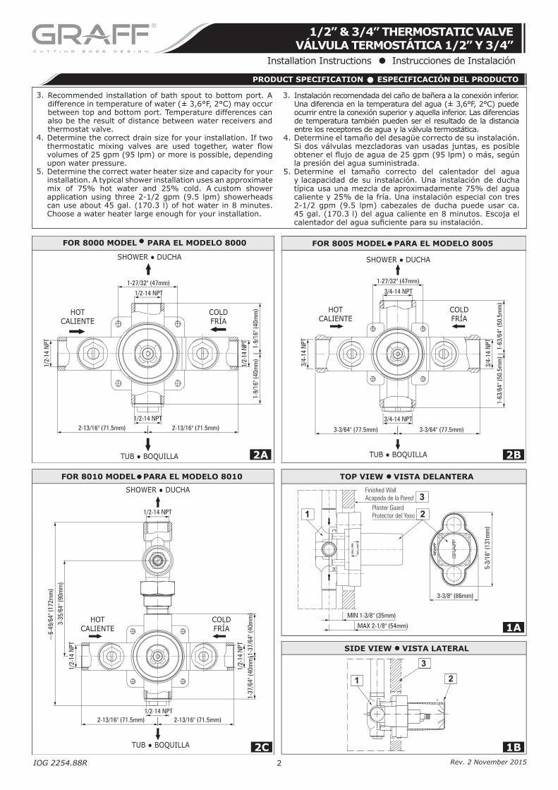
5. Determine the correct water heater size and capacity for your installation. A typical shower installation uses an approximate mix of 75% hot water and 25% cold. A custom shower application using three 2-1/2 gpm (9.5 lpm) showerheads can use about 45 gal. (170.3 l) of hot water in 8 minutes. Choose a water heater large enough for your installation.
4. Determine el tamaño del desagüe correcto de su instalación. Si dos válvulas mezcladoras van usadas juntas, es posible
la presión del agua suministrada.5. Determine el tamaño correcto del calentador del agua
y lacapacidad de su instalación. Una instalación de ducha típica usa una mezcla de aproximadamente 75% del agua caliente y 25% de la fría. Una instalación especial con tres 2-1/2 gpm (9.5 lpm) cabezales de ducha puede usar ca. 45 gal. (170.3 l) del agua caliente en 8 minutos. Escoja el
PRODUCT SPECIFICATION • ESPECIFICACIÓN DEL PRODUCTO
1
3
2
3. Recommended installation of bath spout to bottom port. A difference in temperature of water (± 3,6°F, 2°C) may occur between top and bottom port. Temperature differences can also be the result of distance between water receivers andthermostat valve.
3. Instalación recomendada del caño de bañera a la conexión inferior. Una diferencia en la temperatura del agua (± 3,6°F, 2°C) puede ocurrir entre la conexión superior y aquella inferior. Las diferencias de temperatura también pueden ser el resultado de la distanciaentre los receptores de agua y la válvula termostática.
Rev. 2 November 2015
IOG 2254.88R Rev. 1 June 2010 IOG 2254.88R 3
1/2” & 3/4” THERMOSTATIC VALVEVÁLVULA TERMOSTÁTICA 1/2” Y 3/4”
Installation Instructions Instrucciones de Instalación
• Shut off the main water supply. • Observe all local plumbing codes. • The valve is calibrated to 100°F (38°C) setting. • Factory calibrated inlet conditions are: - Hot and cold water pressure = 43-1/2 psi (3.05 bar). - Hot water supply temperature = 149°F (65°C). - Cold water supply temperature = 59°F (15°C). • If inlet conditions differ from those used during factory
calibration, it may be necessary to re-calibrate the valve after installation. The installer must check the mixed flow temperature after installation and adjust the valve as needed according to the instructions.
• This valve complies with ASME A112.181M, ASSE 1016 and CSA B125.
• Cerrar el suministro principal del agua.• Observar todos los códigos locales de instalación.• La válvula está calibrada para la temperatura de 100°F
(38°C).• Las condiciones de entrada del agua calibradas en la fábrica
son las siguientes: - Presión del agua caliente y fría = 43-1/2 psi (3.05 bar). - Temperatura del agua caliente = 149°F (65°C). - Temperatura del agua fría = 59°F (15°C). • Si sus condiciones son diferentes de las calibradas en la
fábrica, puede resultar necesario recalibrar la válvula después de su instalación. El instalador tiene que controlar la temperatura del flujo mezclado después de la instalación y ajustar la válvula, si es necesario, siguiendo las instrucciones.
• Esta válvula está conforme con ASME A112.181M, ASSE 1016 y CSA B125.
NOTES TO OBSERVE DURING INSTALLATION • ADVERTENCIAS DE OBSERVAR DURANTE LA INSTALACIÓN
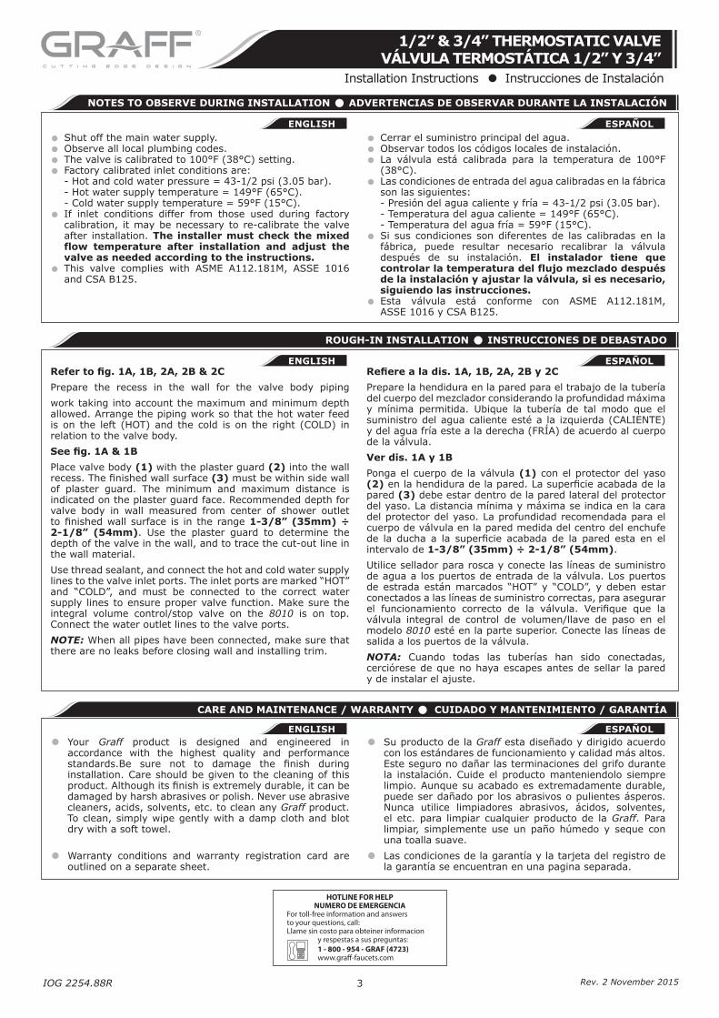
Refer to fig. 1A, 1B, 2A, 2B & 2C
Prepare the recess in the wall for the valve body piping
work taking into account the maximum and minimum depth allowed. Arrange the piping work so that the hot water feed is on the left (HOT) and the cold is on the right (COLD) in relation to the valve body.
See fig. 1A & 1B
Place valve body (1) with the plaster guard (2) into the wall recess. The finished wall surface (3) must be within side wall of plaster guard. The minimum and maximum distance is indicated on the plaster guard face. Recommended depth for valve body in wall measured from center of shower outlet to finished wall surface is in the range 1-3/8” (35mm) ÷ 2-1/8” (54mm). Use the plaster guard to determine the depth of the valve in the wall, and to trace the cut-out line in the wall material.
Use thread sealant, and connect the hot and cold water supply lines to the valve inlet ports. The inlet ports are marked “HOT” and “COLD”, and must be connected to the correct water supply lines to ensure proper valve function. Make sure the integral volume control/stop valve on the 8010 is on top. Connect the water outlet lines to the valve ports.
NOTE: When all pipes have been connected, make sure that there are no leaks before closing wall and installing trim.
Refiere a la dis. 1A, 1B, 2A, 2B y 2C
Prepare la hendidura en la pared para el trabajo de la tubería del cuerpo del mezclador considerando la profundidad máxima y mínima permitida. Ubique la tubería de tal modo que el suministro del agua caliente esté a la izquierda (CALIENTE) y del agua fría este a la derecha (FRÍA) de acuerdo al cuerpo de la válvula.
Ver dis. 1A y 1B
Ponga el cuerpo de la válvula (1) con el protector del yaso (2) en la hendidura de la pared. La superficie acabada de la pared (3) debe estar dentro de la pared lateral del protector del yaso. La distancia mínima y máxima se indica en la cara del protector del yaso. La profundidad recomendada para el cuerpo de válvula en la pared medida del centro del enchufe de la ducha a la superficie acabada de la pared esta en el intervalo de 1-3/8” (35mm) ÷ 2-1/8” (54mm).
Utilice sellador para rosca y conecte las líneas de suministro de agua a los puertos de entrada de la válvula. Los puertos de estrada están marcados “HOT” y “COLD”, y deben estar conectados a las líneas de suministro correctas, para asegurar el funcionamiento correcto de la válvula. Verifique que la válvula integral de control de volumen/llave de paso en el modelo 8010 esté en la parte superior. Conecte las líneas de salida a los puertos de la válvula.
NOTA: Cuando todas las tuberías han sido conectadas, cerciórese de que no haya escapes antes de sellar la pared y de instalar el ajuste.
ROUGH-IN INSTALLATION • INSTRUCCIONES DE DEBASTADO
CARE AND MAINTENANCE / WARRANTY • CUIDADO Y MANTENIMIENTO / GARANTÍA
• Your Graff product is designed and engineered in accordance with the highest quality and performance standards.Be sure not to damage the finish during installation. Care should be given to the cleaning of this product. Although its finish is extremely durable, it can be damaged by harsh abrasives or polish. Never use abrasive cleaners, acids, solvents, etc. to clean any Graff product. To clean, simply wipe gently with a damp cloth and blot dry with a soft towel.
• Warranty conditions and warranty registration card are outlined on a separate sheet.
• Su producto de la Graff esta diseñado y dirigido acuerdo con los estándares de funcionamiento y calidad más altos. Este seguro no dañar las terminaciones del grifo durante la instalación. Cuide el producto manteniendolo siempre limpio. Aunque su acabado es extremadamente durable, puede ser dañado por los abrasivos o pulientes ásperos. Nunca utilice limpiadores abrasivos, ácidos, solventes, el etc. para limpiar cualquier producto de la Graff. Para limpiar, simplemente use un paño húmedo y seque con una toalla suave.
• Las condiciones de la garantía y la tarjeta del registro de la garantía se encuentran en una pagina separada.
HOTLINE FOR HELPNUMERO DE EMERGENCIA
For toll-free information and answersto your questions, call:Llame sin costo para obteiner informacion
y respestas a sus preguntas:1 - 800 - 954 - GRAF (4723)www.graff-faucets.com
ESPAÑOL
ESPAÑOL
ESPAÑOL
ENGLISH
ENGLISH
ENGLISH
Rev. 2 November 2015
IOG 2254.88R 4
CUSTOM SHOWER CONFIGURATION FOR 1/2” THERMOSTATIC VALVECONFIGURACIÓN EJEMPLAR DE DUCHA PARA LA VÁLVULA TERMOSTÁTICA 1/2”
GENERAL GUIDELINES FOR PLANNING SHOWER SYSTEM•INSTRUCCIONES GENERALES PARA PLANEAR EL SISTEMA DE LA DUCHA
CUSTOM SHOWER CONFIGURATION FOR 3/4” THERMOSTATIC VALVECONFIGURACIÓN EJEMPLAR DE DUCHA PARA LA VÁLVULA TERMOSTÁTICA 3/4”
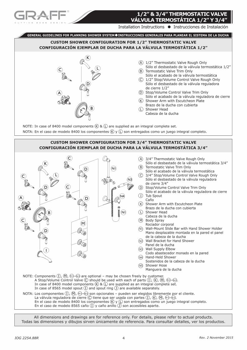
NOTE: Components I , M , N-1–N-5 are optional – may be chosen freely by customer. A Stop/Volume Control Valve C should be used with each of parts I , K , M , N-1–N-5. In case of 8400 model components K & L are supplied as an integral complete set. In case of 8565 model spout I and spout ring J are available separately.
NOTA: Los componentes I , M , N-1–N-5 son opcionales – pueden ser elegidos libremente por el cliente. La válvula reguladora de cierre C tiene que ser usada con partes I , K , M , N-1–N-5. En el caso de modelo 8400 los componentes K y L son entregados como un juego integral completo. En el caso de modelo 8565 caño I y caño anillo J son accesibles aparte.
NOTE: In case of 8400 model components K & L are supplied as an integral complete set.
NOTA: En el caso de modelo 8400 los componentes K y L son entregados como un juego integral completo.
All dimensions and drawings are for reference only. For details, please refer to actual products.Todas las dimensiones y dibujos sirven únicamente de referencia. Para consultar detalles, ver los productos.
A
LC
B
D
K
A
C
B
M
D
D
C
C
C
D
K
L
I
D
N1
N4
N3
N1
A 3/4” Thermostatic Valve Rough Only Sólo el desbastado de la válvula termostática 3/4” B Termostatic Valve Trim Only Sólo el acabado de la válvula termostática C 3/4” Stop/Volume Control Valve Rough Only Sólo el desbastado de la válvula reguladora de cierre 3/4” D Stop/Volume Control Valve Trim Only Sólo el acabado de la válvula reguladora de cierre I Tub Spout Caño K Shower Arm with Escutcheon Plate Brazo de la ducha con cubierta L Shower Head Cabeza de la ducha M Body Spray Rociador corporal N1 Wall-Mount Slide Bar with Hand Shower Holder Mano desplazable montada en la pared el panel de la cabeza de la ducha N2 Wall Bracket for Hand Shower Panel de la ducha N3 Wall Supply Elbow Codo abastecedor monado en la pared N4 Hand-Held Shower Sostenidos de la cabeza de la ducha N5 Shower Hose Manguera de la ducha
A 1/2” Thermostatic Valve Rough Only Sólo el desbastado de la válvula termostática 1/2” B Termostatic Valve Trim Only Sólo el acabado de la válvula termostática C 1/2” Stop/Volume Control Valve Rough Only Sólo el desbastado de la válvula reguladora de cierre 1/2” D Stop/Volume Control Valve Trim Only Sólo el acabado de la válvula reguladora de cierre K Shower Arm with Escutcheon Plate Brazo de la ducha con cubierta L Shower Head Cabeza de la ducha
1/2” & 3/4” THERMOSTATIC VALVEVÁLVULA TERMOSTÁTICA 1/2” Y 3/4”
Installation Instructions Instrucciones de Instalación
Rev. 2 November 2015