³1$12 -refrigerator for eco-friendly and clean environment
TRANSCRIPT

“NANO-REFRIGERATOR FOR ECO-FRIENDLY
AND CLEAN ENVIRONMENT”
PROJECT REPORT
Submitted to
Department of Science,Technology & Environment
Puducherry 605005
Submitted by
D.SENDIL KUMAR
Principal Investigator
Department of Mechanical Engineering
Sri Ganesh College of Engineering and Technology
Puducherry – 607 402

1
CHAPTER 1
INTRODUCTION
1.1. REFRIGERATION
Refrigeration may be defined as the process of achieving and maintaining a
temperature below that of the surroundings, the aim being to cool some product or
space to the required temperature. One of the most important applications of
refrigeration has been the preservation of perishable food products by storing them at
low temperatures. Refrigeration systems are also used extensively for providing
thermal comfort to human beings by means of air conditioning.
1.2 INDIAN SCENARIO
The refrigeration and air conditioning sector in India has long history from the
early years of last century. India is presently producing R134a, R22, R717 and hydro
carbon based refrigeration and air conditioning units in large quantities. The use of
CFC refrigerants in new systems was stopped since the year 2002. The factors that
dictate the adoption of a particular refrigerant apart from its suitability for the specific
application are its availability and cost. The halogenated refrigerants such as R12,
R22, R134a and natural refrigerant like R717 are readily available at low prices. The
Hydrocarbon (HC) and Hydro Fluro Carbon (HFC) mixtures (such as R404a, R407,
and R410A) are not currently manufactured indigenously and hence have to be
imported at a higher cost. This is likely to affect the growth in refrigeration and air
conditioning sector in India and also the total conversion to environmental friendly
alternatives in the near future.
1.3 DOMESTIC REFRIGERATION
The Indian household refrigerator industry is more than 50 years old. Eight
major domestic refrigerator manufactures were catering this market, of which four are
manufacturing hermetic compressors. Domestic refrigerators manufactured in India
range in capacities from 65 to 580 l. Most of the currently produced Indian

2
refrigerators uses R134a as refrigerant. The choice of alternative to R134a is narrowed
down to R152a and hydrocarbon refrigerants. Refrigerators manufactured before 2000
were still running on R12. To full fill the objectives of the Montreal Protocol, R12 has
to be replaced by either hydrocarbon mixtures or R134a/hydrocarbon mixtures without
modification in the existing system.
1.4 COMMERCIAL AND INDUSTRIAL REFRIGERATION
Most of commercial freezers like chest freezers, bottle coolers, visi coolers,
display cabinets, water coolers and walk in coolers are using R134a and R12 as the
refrigerant. Annual production of commercial refrigerated cabins (such as chest
freezers, display cabinets , bottle coolers and visi coolers), water coolers and walk in
coolers in India were estimated to be about 40,000, 27000,and 500 units respectively.
About 80% of these units are manufactured by small and medium enterprises
(Ministry of Environment and Forest, 2005). The choice of suitable alternative to
R134a in commercial applications is R152a and hydrocarbon mixtures. The estimated
population of milk chilling and cold storage in India was about 14,000. Most of the
cold storage and milk chilling plants are working on ammonia and some on R502.
Ammonia will dominate the industrial refrigeration sector due to its favorable
environment properties (zero ODP and GWP). The alternative choice for R502 is 507
and hydrocarbon mixtures for low temperature industrial applications.
1.5 AIR CONDITIONERS, HEAT PUMPS AND CHILLERS
In India it is estimated that one million room air conditioners is being
manufactured with R22 as refrigerant every year, which compromises of window, split
and packaged air conditioning units (Devotta et al., 2005). The capacity of the
windows air conditioners ranges from 0.5 TR to 2 TR. The choice of alternative to
R22 in air conditioning applications is R407 and R410 which are available in the
Indian market. Annually about 4000 central air conditioning chillers were installed,
most of these chillers was based on R22 and R11. Very limited chillers were presently
installed with R123 due to the lack of availability on this refrigerant. The long – term
alternative to R11 and R22 for the chiller applications is R123.

3
1.6 AUTOMOBILE AIR CONDITIONERS
Three manufactures in India are producing about 50,000 units of automobile
air conditioners annually. Most of these units are R134a based system. The choice of
alternative to R134a is R152a and hydrocarbon mixtures. The car air conditioning
units installed before 2000 were still running on R12 only. The choice of alternative to
R12 and R134a is the mixture composed of R134a with hydrocarbon mixture or
hydrocarbon mixtures and R152a.
Table 1.1 Future options in refrigerants
Equipment Application Future options
Refrigerator
Walk in coolers
Chest Freezer
Air conditioners
Chillers
Cold Storage
Household (domestic)
Commercial
Commercial
Residential and
Commercial
Automobile
Industrial
Industrial
HC mixtures, R152a
HC mixtures, R134a/ HC
mixtures, R152a
HC mixtures, R152a
R290, R407C, R410A,
R407C/ HC mixtures,
R152a HC mixtures
R123
Ammonia
The halogenated refrigerants like R22, R134a, R123, R404A, R407C, R410A and
507 will continue to be dominating during the next decade due to its high efficiency,
safety and their current strong position in the Indian market. The Technologies
identified for manufacturing new products in this sector are listed in table 1.1

4
1.7 ENVIRONMENTAL IMPACTS
Green House gas (GHG) emissions from fossil fuel combustion for power
generation and emission of halogenated refrigerants from vapour compression based
refrigeration , air conditioning and heat pump systems contribute significantly to
global warming. A reduction in GHG emissions can only be achieved by using
environment friendly and energy efficient refrigerants. The high environmental
impacts due to halogenated refrigerant emissions lead to identifying a long-term
alternative to meet all the system requirements including system performance,
refrigerant –lubricant interaction, energy efficiency, safety and service. Halogenated
refrigerants are extensively used in the refrigeration and air conditioning industries
over many decades due to their excellent thermodynamic and thermo-physical
properties. As per the Montreal Protocol 1987, developing countries like India, with a
per capita consumption less than 0.3 kg of ozone depletion substance have been
categorized as Article-5 countries. These countries are required to phase out all Chloro
Fluro carbons (CFCs) by 2010 and all hydro Chloro Fluro carbons (HCFCs) by 2040.
HFC refrigerants are considered as one among the six targeted green house gas under
Kyoto protocol of United Nations Framework Convention on Climate Change
(UNFCCC) in 1997.
1.8 OZONE LAYER DEPLETION
The first major environmental impact that struck the refrigeration based
industries is Ozone Depletion Potential (ODP) due to manmade chemicals into the
atmosphere. About 90% of the ozone exists in the stratosphere between 10 and 50 km
above the earth surface. Molena and Rowland (1974) give in detail that chlorine based
refrigerants are stable enough to reach the stratosphere, where the chlorine atoms act
as catalyst to destroy the stratospheric ozone layer which protects the earth surface
from direct ultra violet rays.

5
1.9 GLOBAL WARMING POTENTIAL (GWP)
The second major environmental impact is GWP, which is due to the absorption of
infrared emissions from the earth, causing an increase in global earth surface
temperature. While solar radiation at 5800 K and 1360 W/m2 arrives the earth , more
than 30% is reflected back into space and most of the remaining radiation passes
through the atmosphere and reaches the ground. This solar radiation heats up the earth,
which is approximately as a black body radiating energy with a spectral peak in the
infrared wavelength range. This infrared radiation cannot pass through the atmosphere
because of absorption by GHG including the halogenated refrigerants.
1.10 NANO FLUIDS
Nanofluids are engineered colloids which consist of a base fluid with Nano
sized particles (1-100 nm) suspended within them. Common base fluids include water,
organic liquids (e.g. ethylene, tri-ethylene-glycols, refrigerants, etc.), oils and
lubricants, bio-fluids, polymeric solutions and other common liquids. Materials
commonly used as nanoparticles include chemically stable metals (e.g., gold, copper),
metal oxides (alumina, silica, zirconia, Titania), oxide ceramics (e.g. Al2O3, CuO),
metal carbides (e.g. SiC), metal nitrides (e.g. AIN, SiN), carbon in various forms (e.g.,
diamond, graphite, carbon nano tubes, fullerene) and functionalized nanoparticles. By
suspending nanoparticles in conventional heat transfer fluids, the heat transfer
performance of the fluids can be significantly improved. As a fluid class, Nanofluids
have a unique feature which is quite different from those of conventional solid-liquid
mixtures in which millimetre and/or micrometre-sized particles are added. Such
particles settle rapidly, clog flow channels, erode pipelines and cause severe pressure
drops. All these shortcomings prohibit the application of conventional solid-liquid
mixtures to micro channels while nano fluids instead can be used in micro-scale heat
transfer. Heat transfer performance of the nano fluid is superior to that of the original
pure fluid because the suspended ultrafine particles remarkably increase the thermal
conductivity of the mixture and improve its capability of energy exchange.

6
According to the application, nano fluids are classified as heat transfer nano
fluids, tribological nano fluids, surfactant and coating nano fluids, chemical nano
fluids, process/extraction nano fluids, environmental (pollution cleaning) nano fluids,
bio- and pharmaceutical nano fluids and medical nano fluids (drug delivery, functional
and tissue-cell interaction).
1.11 OBJECTIVES AND SCOPE OF THE PRESENT STUDY
Several investigations have been carried out to tackle the problem of Global
Warming and Ozone layer depletion with the usage of alternative refrigerants in the
refrigeration system. Hence it is felt that a detailed investigation on the possibility of
exploring an new alternative refrigerant and addition of nano additives to the refrigerant
and studying the effect of surfactant would be a worthwhile attempt. Accordingly the
specific objectives of the present research work comprises of which are as follows:
The most commonly used commercial refrigerant R134a and the proven
alternative R152a were blended and the new hybrid refrigerant was prepared and
the corresponding performance was investigated.
Nano additives such as ZnO, CuO and Al2O3 were blended with R152a refrigerant
and their corresponding performance on the same system was investigated. Nano
additives of Al2O3, CuO and ZnO of 0.05%v ,0.1 % v and 0.15%v concentration
with particle size of 40-50 nm and 150 gm of R152a was charged and tests were
conducted. The compressor discharge temperature, discharge pressure and
evaporator temperature, Coefficient of performance (COP), vapour pressure,
volumetric cooling capacity (VCC) were measured. An experimental test rig is
designed and fabricated indigenously in the lab to carry out the investigations.
Nanoparticles with refrigerant mixture were used in HFC R152a refrigeration
system. The system performance with nanoparticles was then investigated.
The effect of surfactant on the system performance was investigated .Two types
of surfactants Sodium dodecyl sulfate (SDS) anionic surfactant and Cetyl tri
methyl ammonium bromide (CTAB) cationic surfactant were added to the

7
compressor oil at their Critical Micelle Concentration (CMC) values and the
system performance was investigated.
The scope of this work is limited based on the following
1. Three types of nano additives namely Al2O3, CuO and ZnO were selected for
study.
2. The blending ratio of R134a and R152a were chosen as 30:70, 50:50, and
70:30 in this study
3. The concentration of nano additives were chosen as 0.05%v, 0.1 % v and
0.15%v in this investigation.
4. Only two surfactants viz. sodium dodecyl sulfate (SDS) an Cetyl tri methyl
ammonium bromide (CTAB) representing anionic and cationic class of
surfactants respectively have been employed in this investigation
1.12 ORGANIZATION OF THESIS
This thesis contains nine chapters with and introduction to the problem in first
chapter followed by objectives and scope of the present study. In chapter 2, a
comprehensive literature review on refrigeration, blending of refrigerants,
addition of Nano additives in refrigeration system and the influence of the
surfactants on the performance of the system are presented. The materials and
methods including the refrigeration system, its types and the lubricant used in the
refrigeration system were presented in chapter 3, chapter 4 presents the details of
a Nanoparticles and the surfactants along with their properties. In chapter 5 the
fabricating of the experimental setup along with synthesis of Nano fluids are
presented. Chapter 6 presents the study on blending of R152a and R134a along
with their results and discussion. In chapter 7 a detailed experimental study on the
performance of nano additives in R152a refrigeration system was carried out. The
effect of surfactants on the system performance was discussed in chapter 8.

8
Conclusions and the scope for future research work are highlighted in chapter 9.
The overall outline of the present research study is presented in Fig. 1.1

9
Fig. 1.1 Outline of research study on nanoadditive and surfactants in refrigeration
Vapour Compression Refrigeration System
Blending of
Refrigerant R134a
and R152a
Synthesis of Nano Refrigerant
R152a + Nano
ZnO
R152a + Nano
CuO
R152a + Nano
Al2O3
Characterization
SEM
Micrograph
EDX Diffractogram
Performance Test
Discharge Pressure &
Temperature
Vapour Pressure
Pressure ratio
Compressor Input Power
Coefficient of performance
Functionalizing of nanoparticles
Effect of
Surfactants
SDS, CTAB

10
CHAPTER 2
LITERATURE REVIEW
2.1 INTRODUCTION
Air conditioners and refrigerator-freezers are major energy users in a
household environment and hence efficiency improvement of these appliances can be
considered as an important step to reduce their energy consumption along with the
environmental pollution prevention. Energy efficiency standards and labels are
commonly used tools to reduce the energy uses for household appliances for many
countries around the world.
The refrigeration sector is the midst of an unprecedented transition crisis
catalysed by environmental concerns with the impact of the refrigerant emissions. As
per the Monteral Protocol, CFC12 is being phased out following a stipulated time
frame. The developed countries have already phased out this substances and the
developing countries are to totally phase out the CFCs by 2010 as per the Montreal
Protocol. Most of the developing countries are drastically reducing their CFC
production and consumption. This demand for a suitable substitute for CFC12 for
possible retrofitting of existing systems as well as for new systems.
The refrigerator production and sales rate in developing countries made
significant leaps only in the last decade and for another 15 years all the refrigerators
sold would one way or other come for service. Due to the reduction in production of
CFCs and non availability and high cost of CFC refrigerants, the existing CFC based
refrigerators ( in India approximately 25 million) may have to be dispensed with as
and when some service problems arise, which the economy of a developing country
would not permit. To retrofit the existing CFC12 refrigerators with eco friendly
technology two matching refrigerants are available, namely, HFC134a and HC blend.
HFC134a systems do have inherent service issues because of the POE oil in the
compressor, as HFC134a is not miscible with conventional mineral oil. On the other
hand, HC blends have the problems of flammability and limitation in the charge

11
quantity due to safety (fire hazard) regulations. Hence, it would be a significant benefit
for the RAC technicians in the service sector if HFC 134a can be made to work with
mineral oil. It has been reported that the oil miscibility problem for HFC134a in
mineral oil could be solved by adding suitable quantity of HC additive. (S. Joseph
Sekhar et al. 2004)
2.2 BLENDING OF REFRIGERANTS
The environmental concerns with the impact of refrigerant emissions lead to
the importance in identifying a long-term alternative to meet all requirements in
respect of system performance and service.
Mao-Gang – He et al. (2005) used a mixture of HFC152a/HFC125 as
refrigerant for domestic refrigerator and the performance was analysed. The results
indicate the HFC152a/HFC125 mixture in the composition of 0.85 mass fraction of
HFC152a as similar performance with the existing refrigerant CFC12. Experimental
research on the main refrigeration performances of domestic refrigerators was
conducted, under the different proportions and charge amounts, when
HFC125a/AFC125 is used to substitute CFC12 as a “drop-in” refrigerant. The
experimental results indicate that the refrigeration performances of the domestic
refrigerator charged with the new refrigerant can meet the requirement of the National
Standard of China, under the appropriate proportion and the optimum charge amount.
The optimum charge amount that determine based on the energy consumption and the
main operating parameters the precision of the charged amount was ±1g. The purity
used in their analyses was not lower than 99.5%. In the mass proportion
HFC152a/HFC125 is 15.13/84.87 wt% and the charge amount is 97g, the energy
consumption is lowest as 1.156 kW/h/per day. They concluded that the mixing
refrigerant HFC152a/HFC125 proposed in their study is a long term alternative to
CFC12.

12
M.S. Kim et al. (1994) conducted a performance evaluation of two azeotropic
refrigerant mixtures of HFC134a with HC290 and HC600a on heat pump and
established that COP of the CFC12 heat pumps improved by 3.5% when they were
retrofitted with a mixture of HFC134a/HC600a (80:20) by weight.
D.Jung et al. (1996) tested the hydrocarbon mixture of HC290/HC600a
mixture at various composition on a domestic refrigerator at various composition and
found that with 0.55-0.6 mass percentage of HC600a yielded 3 - 4% increase in energy
efficiency as compared to CFC12.
Miguel Padilla et al. (2010) studied the energy analysis of the impact of direct
replacement of R12 with the zeotropic mixture R413a on the performance of a
domestic vapour compression refrigeration system. They found that the evaporator
outlet temperature ranged from 150C to -100 C. the overall energy performance of the
system working with R413a is consistently better than that of R12.
Alka Bani Agarwal and Vipin Shrivastava (2010) retrofitted a vapour
compression refrigeration trainer by an eco-friendly refrigerant. After year’s successful
deliberations for tackling the grievous problem of ozone depletion, the United
Nation’s environmental protection agency concluded multinational agreement called
“Monteral Protocol” for controlling the use of gases threatening the ozone layer. The
successful implementation of the “Monteral Protocol” in developed countries is being
appreciated for its significant reduction in emission level of ozone depleting
substances Now it is turn of developing countries to fulfill their obligation of Montreal
Protocol. The dead line for complying with the phase out of Chlorofluro carbon in
developing countries like India is 2010. The refrigeration industry has accepted the
challenge of chloroflourocarbons phase out and new eco-friendly refrigerant like
hydroflurocarbons and hydrocarbons are replacing chloroflurocarbons in all
commercial and industrial application. Vapour compression refrigeration trainer is an
important equipment of thermal engineering lab of mechanical engineering department
which operated using chloroflurocarbon 12. CFC12 is the most important member of
CFC refrigerants which are being targeted for phase out in India by 2010. Performance
valuation of many eco-friendly hydrocarbon refrigerants for replacing CFC12 in the

13
trainer has been done and a suitable drop in alternative refrigerant for retrofitted has
been identified.
Zhijing Liu et al. (2012) tested R290/R600 mixture as a drop-in susbstitute in a
20-cubic feet, single-evaporator, auto defrost, top mount, conventional domestic
refrigerator/freezer. All the hardware remained the same, only the capillary tube was
lengthened to achieve the optimum performance. The best result with an optimized
R290/R600 blend was 6% savings compared to the baseline test with R12. In the
second part of the research, an 18.0 cubic-feet, auto defrost, top mount, domestic
refrigerator was used for experiments. Having tested for the single-evaporator baseline
performance, the unit was converted to a two-evaporator modified Lorenz-Meutzner
cycle. The optimum performance of the modified unit yield 14.6% and 16.7% energy
savings with binary mixtures R290/nc5, and R290/R600, respectively. A ternary
mixture R290/R600/nc5 with 17.3% energy savings proved to be better than the binary
mixtures. The superior transport properties of the hydrocarbon mixture are believed to
be responsible for their better test performance.
A.S. Dalkilic and S. Wongwises (2010) made a performance comparison of
vapour-compression refrigeration system using various alternative refrigerants A
theoretical performance study on a traditional vapour-compression refrigeration
system with refrigerant mixtures based on HFC134a, HFC152a, HFC32, HC290,
HC1270, Hc600, and HC600a was done for various ratios and their results are
compared with CFC12, CFC22 and HFC134a as possible alternative replacements.
Abhishek Tiwari et al. (2011) conducted on experimental study of R404a and
R134a, environment-friendly refrigerants with zero ozone depletion potential (ODP)
and low global warming potential (GWP), to replace R134a in domestic refrigerator. A
refrigerator designed and developed to work with R134a was tested, and its
performance using R404a was evaluated and compared with its performance when
R134a was used. The results obtained showed that the design temperature and pull-
down time set by International Standard Organization (ISO) for small refrigerator were
achieved earlier using refrigerant R-401a than using R-134a. The system consumed

14
less energy when R134a was used. The performance of R404a in the domestic
refrigerator was constantly better than those of R134a throughout all the operating
conditions, which shows that R404a can be used as replacement for R134a in domestic
refrigerator.
M. Mohanraj et al. (2009) conducted an experimental investigation with
hydrocarbon refrigerant mixture (composed of R290 and R600a in the ratio of
45.2:54.8 by weight) as an alternative to R134a in a 2001 single evaporator domestic
refrigerator. Continuous running tests were performed under different ambient
temperatures (24, 28, 32, 38 and 430 C), while cycling running (ON/OFF) tests were
carried out only at 320C ambient temperature. The results showed that the hydrocarbon
mixture has lower values of energy consumption; pull down time and ON time ratio by
about 11.1%, 11.6% and 13.2% respectively with 3.25-3.6% higher coefficient of
performance (COP). The above hydrocarbons refrigerant mixture could be the best
long term alternative to phase out R134a.
B.O. Bolaji et al. (2011) analaysed the performances of the three ozone Hydro
fluorocarbon (HFC) refrigerants (R32, R134a and R512a) in a vapour compression
refrigeration system were investigated experimentally and compared. The results
obtained showed that R32 yielded undesirable characteristics, such as high pressure
and low co-efficient of performance (COP). Comparison among the investigated
refrigerants confirmed that R152a and R134a have approximately the same
performance, but the best performance was obtained from the used of R152a in the
system. As a result, R152a could be used as a drop-in replacement for R134a in vapour
compression refrigerant system. The COP of R152a obtained was higher than those of
R134a and R32 by 2.5% and 14.7% respectively. Also, R152a offers the best desirable
environmental requirements; zero ozone potential and very low global warming
potential.
S. Joseph Sekhar et al. (2004) presented two potential substitutes, namely,
HFC134a and HC blends are available as drop in substitutes for CFC12. HC
(hydrocarbon) refrigerants do have inherent problems in respect flammability.
HFC134a is neither flammable nor toxic. But HFCs (hydro fluorocarbons) are not

15
compatible with mineral oil and the oil change is a major issue while retrofitting. The
above techno-economic feasibility issue to retrofit the existing CFC12 systems with
ozone friendly refrigerant and the energy efficiency of the system are the challenges in
the domestic refrigeration sector. They carried out an experimental analysis in a 165
litre CFC12 household refrigerator retrofitted with eco-friendly refrigerant mixture
HFC134a/HC290/HC600a without changing the mineral oil. Its performance, as well
as energy consumption, is compared with the conventional one. As the system has
been running successfully for more than 12 months consumption by 4 to 11% and
improve the actual COP by 3 to 8% from that of CFC12. The new mixture also
showed 3 to 12% improvement in theoretical COP. The overall performance has
proved that the new mixture could be an eco-friendly substitute to phase out CFC12.
Ching-Song Jwo et al. (2009) investigated to apply the mixture of hydrocarbon
refrigerants, R290 and R-600a with each 50% component ratio, instead of the
refrigerant R134a for home refrigerators. The hydrocarbon refrigerants of R290 and
R600a are friendly for environmental protection and have good refrigerating behavior
in comparison with CFCs, HVFs or HFCs refrigerants. The experiments used a 440
litre capacity home refrigerator as test facility, which officially works with 150g
R134a refrigerant was replaced by varied mass hydrocarbon refrigerant, which was
mixed by R290 and R600a with each 50% component ratio. The results show that
refrigerating effect is improved by using hydrocarbon refrigerant. Moreover, the total
consumed energy is saved 4.4% and applied mass of refrigerant is reduced 40%
2.2.1 Technical difficulties of mixed alternatives
The technical difficulties of the alternative refrigerant mixtures are listed
below:
(a) The major problem of the refrigerant mixtures is the occurrence of pinch points
in the condensers and evaporators during phase change due to non-linear
variation in refrigerant properties, which reduces condenser and evaporation
effectiveness (Venkatarathnam and Srinivasamoorthy, 1999).

16
(b) Non-isothermal behavior of the refrigerant mixtures creates ambiguity in
selecting the components of the refrigeration system from the manufacture‘s
catalogue.
(c) Perfect glide matching can be achieved only in certain heat exchange
geometries such as shell and tube, concentric tubes, counter flow and flat plate
heat exchangers.
(d) Conventional method of heat exchangers design is not fully valid for the case
mixed refrigerants (Rajaoaksha, 2007)
(e) Non-linearity of the mixtures influences to decreasing the temperature
difference at inlet and outlet may lead to increase in heat exchanger area to
achieve the desired capacity.
(f) Composition shift due to leakage of refrigerant of the mixed refrigerants leads
to change in pressure, temperature, capacity and efficiency (Johansson and
Lundqrist, 2001)
(g) Mixed refrigerants require liquid receiver and suction line accumulator due to
composition variation in phase change (Rajapaksha and Suen, 2004)
2.3 NANO FLUIDS
2.3.1 Historical overview
It is well known fact that conventional fluids such as water, ethylene glycol
(EG) and engine oils have low thermal conductivity and the efficiency of heat transfer
with a very small temperature difference is limited. There is a need for energy efficient
working fluids to improve the energy conversion system. However the coefficient of
convective heat transfer depends on thermal conductivity of the fluid. The thermal
conductivity of fluid is improved by adding micrometer or millimeter sized solid
materials to the base fluids. The solid additives improves the thermal conductivity of
the base fluid. The practical applications are limited due to the clogging of flow
channels, sedimentation of large particles and causing pressure drops. The above
drawbacks are overwhelmed by using a new class of fluids called nanofluids. Choi in
Argonne National Laboratory introduced the concept of nanofluids. Nanofluids are a
new class of solid-liquid composite materials consisting of solid nanoparticles (in the

17
range of 1-100 nm) or carbon nano tubes, dispersed in a heat transfer fluid such as
ethylene glycol, water or oil .
2.3.2 Techniques used in synthesis of nanofluids
Several researchers carried out the synthesis of nanofluids using two step and single
step method. In case of two step method, the nanoparticles are produced initially and then
it is added into the working fluid in case of single step method the dispersion of
nanoparticle is done directly into the working fluid.
2.3.3 Synthesis of nanofluids using two step method
The preparation of nanofluids is done by mixing the nanoparticles directly into the
base fluid. The nanoparticles are produced at first step and then it is added into the base
fluid as a second step. Xuan and Li (2000) presented a procedure for preparing a
nanofluid which is a suspension consisting of nano phase powders and a base liquid. Two
different kinds of nanofluids are prepared by varying the base fluid. The first one is the
transformer oil based nanofluid which is prepared by adding Cu nanoparticles by 2 and 5
vol % respectively and the suspension are stabilized with the oleic acid. The second is the
preparation of water based copper nanofluid in which Cu nanoparticles are added by 5
vol% and laurate salt is added to stabilize the suspension.
Patel et al. (2003) measured the thermal conductivity of Au nanopaticles in water
and toluene and the size of the nanoparticles used in this study is of 10-20 nm in diameter
by adding citrate as the stabilization agent.
Putnam et al. (2006) prepared nanofluid which consisted the mixtures of C60–
C70 fullerence in toluene and alkanethiolate stabilized Au nanoparticles in ethanol and
toluene by using two step processes for measuring thermal conductivity.

18
Murshed et al. (2005) prepared two kinds of nanofluids of which one is in
spherical shaped TiO2 nanoparticles of diameter 15 nm and the other one is rod shaped
TiO2 nanoparticles of 10 nm in diameter and 40 nm in length for comparing the thermal
conductivity.
Wang et al. (1999) and Lee et al. (1999) measured the thermal conductivity of
Al2O3 and CuO nanofluid which is prepared by two step method using different base
fluids such as water, vacuum pump fluid, engine oil, and ethylene glycol. Experimental
results show that the thermal conductivities of nanoparticle–fluid mixtures are higher
than that of the base fluids.
Wang et al. (2006) prepared water- based multiwall carbon nanotube dispersed
nanofluids using sodium dodecyl sulfate (SDS) dispersions, since the fibers are entangled
in the aqueous suspension. However, the heat transfer performance of the nanofluids is
affected by the addition of dispersions in fluids, especially at high temperature.
Hong et al. (2005) prepared Fe nanofluids with ethylene glycol using Fe
nanocrystalline powder which is synthesized by a chemical vapour condensation process.
To improve the suspension of the nanoparticles, sonication is carried out with high-
powered pulses to improve the dispersion of nanoparticles in the preparation of
nanofluids. After, sonication nanofluids exhibit an enhancement of thermal conductivity.
Thermal conductivity of a Fe nanofluid is increased nonlinearly up to 18% as the volume
fraction of particles is increased up to 0.55 Vol.%.
Liu et al. (2005) using a two-step method prepared CNT nanofluids using
ethylene glycol and synthetic engine oil for measuring thermal conductivity of the
nanofluids and the volume concentration of CNT–ethylene glycol suspensions is below
1.0 Vol. % and that of CNT–synthetic engine oil suspensions is below 2.0 Vol. %.
Results indicate that the CNT–synthetic engine oil suspension has a much higher
enhanced thermal conductivity ratio than that of the CNT–ethylene glycol suspension.

19
The two-step method for preparing nanofluids is a process by dispersing
nanoparticles into base liquids. This step-by step method isolates the preparation of the
nanofluids from the preparation of nanoparticles. As a result, agglomeration of
nanoparticles may take place in both steps, especially in the process of drying, storage,
and transportation of nanoparticles. The agglomeration will not only result in the
settlement and clogging of microchannels, but also decrease the thermal conductivity.
Simple techniques such as ultrasonic agitation or the addition of surfactants to the fluids
are often used to minimize particle aggregation and improve dispersion behavior. Since
nanopowder synthesis techniques have already been scaled up to industrial production
levels by several companies, there are potential economic advantages in using two-step
synthesis methods that rely on the use of such powders. But an important problem that
needs to be solved is the stabilization of the suspension prepared.
2.3.4 Synthesis of nanofluids using single step method
Eastman and Choi (2001) has used a one-step physical synthesis method to
prepare nanofluids, in which Cu vapor was directly condensed into nanoparticles by
contact with a flowing low vapor pressure liquid (ethylene glycol) and the effective
thermal conductivity of ethylene glycol was shown to be increased up to 40% for a
nanofluid consisting of ethylene glycol containing approximately 0.3 Vol% Cu
nanoparticles of mean diameter, 10 nm.
Liu et al. (2006) used the technique of chemical reduction method for synthesis of
nanofluids containing Cu nanoparticles in water without using surfactant as the
dispersant. Thus the synthesized copper nanofluid shows improved thermal conductivity
when compared to pure fluids.
Hong et al. (2005) employed chemical vapour condensation process to synthesis
Fe nanofluids with ethylene glycol. The thermal conductivity of a Fe nanofluid is
increased nonlinearly up to 18% as the volume fraction of particles is increased up to
0.55 Vol. %.

20
Lo et al. (2005) developed submerged arc nano synthesis system for preparing
Cu-based nanofluids with different morphologies and using various dielectric liquids by
selecting pure copper as an electrode as well as the work piece material. Also the
advantage of this method is that allows the production of uniform and well-dispersed
copper nanoparticles without any aggregation.
Zhu et al. (2004) presented a novel one-step chemical method for preparing
copper nanofluids by reducing CuSO4·5H2O with NaH2PO2·H2O in ethylene glycol under
microwave irradiation. By this method non agglomerated and stably suspended Cu
nanofluids were obtained. This method also found to be a fast and efficient for preparing
Cu nanofluids.
The single-step method is a process of combining the preparation of nanoparticles
with the synthesis of nanofluids, for which the nanoparticles are directly prepared by
physical vapour deposition (PVD) technique or liquid chemical method. In this method
the processes of drying, storage, transportation, and dispersion of nanoparticles are
avoided, so the agglomeration of nanoparticles is minimized and the stability of fluids is
increased. But a disadvantage of this method is that only low vapour pressure fluids are
compatible with the process. This limits the application of the method.
2.3.5 Thermo physical properties of nanofluids
Habib Anifar et al. (2013) studied the Brownian and thermophoresis effects on
natural convection of alumina-water nano fluid and found that heat transfer rate decreases
with an increases in nanoparticle volume fraction.
Jahar Sarkar et al. (2013) studied the thermodynamic analysis and optimization of
a two-stage cascade system with a choice of eight natural refrigerants. Their study
reported two selection charts along with tables one for higher coefficient of performance
and the other for highest volumetric capacity.

21
Aminfar et al. (2011) investigated the laminar flow and convective heat transfer
of water – alumina nanofluid in a rectangular micro channel numerically. The results
indicated that usage of nanofluid enhances convective heat transfer and pressure drop in a
microchannel in comparison with pure water.
Liu et al. (2010) investigation discovered that the thermal performance of a mesh
heat pipe can be evidently strengthened by substituting CuO nanofluids for deionized
water under sub-atmospheric pressures.
Tsai et al. (2004) employed gold nanoparticles in nanofluid as working medium
for conventional circular heat pipe and predicted the thermal resistance of the heat pipes
with nanoparticle solution is lower than that with DI water.
Liu et al. (2011) performed an experimental work on the micro-grooved heat pipe
using aqueous nanofluids as the working fluids and reported that addition of Cu and CuO
nanoparticles in the base fluid can apparently improve the thermal performance of the
heat pipe.
Misheck et al. (2006) studied the performance of heat pipe with coarse and fine
pores wick structure. An improvement of heat pipe performance up to a factor of 2 was
reported with such a type of wick.
Tsai et al. (2004) employed gold nanoparticles in nanofluid as working medium
for conventional circular heat pipe and predicted the thermal resistance of the heat pipes
with nanoparticle solution is lower than that with DI water.
2.3.6 Nano fluids for refrigeration
The nanofluid is a new type of heat transfer fluid by suspending nano-scale
materials in a conventional host fluid and has higher thermal conductivity than the
conventional host fluid. The nano refrigerant is one kind of nanofluid and its host fluid is
a refrigerant. A nanorefrigerant has higher heat transfer coefficient than the host
refrigerant and it can be used to improve the performance of the refrigeration systems.
The heat transfer coefficient of a fluid with lower thermal conductivity is larger than that
of a fluid with lower thermal conductivity if the Nusselt numbers of them are the same.

22
Therefore, researches on improving thermal conductivites of nanorefrigerants are
necessary. There are two methods to improve the thermal conductivity of a nano
refrigerant. The first one is to increase the volume fraction of nano scale materials in the
nanorefrigerants and the second one is to use nano-scale materials with high thermal
conductivity (Jiang et al. 2009).
Jiang et al. (2009) showed that the thermal conductivities of carbon nanotube
(CNT) nanorefrigerants are much higher than those of CNT-water Nanofluids or
spherical-nano particle-R113 nanorefrigerants. Authors reported that the smaller the
diameter of CNT is or the larger the aspect ratio of CNT is the larger the thermal
conductivity enhancement of CNT nano refrigerant.
Elcock (2007) found that TiO2 nanoparticles can be used as additives to enhance
the solubility of the mineral oil with hydro fluorocarbon (HFC) refrigerant. Authors also
reported that refrigeration systems using a mixture of HFC134a and mineral oil with TiO2
nano particles appear to give better performance by returning more lubricant oil to the
compressor with similar performance to systems using HFC134a and POE oil.
Hindawi (2009) carried out an experimental study on the boiling heat transfer
characteristics of R22 refrigerant with Al2O3 nano particles and found that the
nanoparticles enhanced the refrigerant heat transfer characteristics with reduced bubble
sizes.
Eastman et al. (1996) investigated the pool boiling heat transfer characteristics of
R11 refrigerant with TiO2 nano particles and showed that the heat transfer enhancement
reached 20% at a particle loading of 0.01g/L.
Liu et al. (2006) investigated the effects of carbon nano tubes (CNTs) on the
nucleate boiling heat transfer of R123 and HFC134a refrigerants. Authors reported that
CNTs increase the nucleate boiling heat transfer coefficient for these refrigerants.
Authors noticed large enhancements of up to 36.6% at low heat fluxes of less than
30kW/m2. Thus, the use of nano particles in refrigeration systems is a new, innovative
way to enhance the efficiency and reliability in the refrigeration system.

23
Bi et al. (2011) conducted an experimental study on the performance of a
domestic refrigerator using TiO2-R600a nanorefrigerant as working fluid. They showed
that the TiO2-R600a system worked normally and efficiently in the refrigerator and an
energy saving 9.6%. They also reported freezing velocity of anno refrigerating system
was more than that with pure R600a system.
N. Subramani et al. (2011) established that addition of nano particles to the
refrigerant results in improvements in the thermo physical properties and heat transfer
characteristics of the refrigerant, thereby improving the performance of the refrigeration
system. Stable nano lubricant works has been prepared for their study. The experimental
studies indicated that the refrigeration system with nano refrigerant works normally. It is
found that the freezing capacity is higher and the power consumption reduces by 25%
when POE oil is replaced by a mixture of mineral oil and alumina nano particles.
Calculation shows that the enhancement factor in the evaporator is 1.53 when nano
refrigerants are used instead of pure refrigerant.
Eed Abdel-Hafez-Hadi et al. (2011) studied the effect of using nano Cu-R134a in
the vapour compression system on the evaporation heat transfer coefficient is
experimentally investigated. An experimental test rig is designed and constructed here for
this purpose. The test section is a horizontal tube in tube heat exchanger made from
copper. The refrigerant is evaporated inside an inner copper tube and the heat load is
provided from hot water that passing in an annulus surrounding the inner tube.
Measurements were performed for heat flux ranged from 10 to 40 kW/m2, using nano
CuO concentration ranged from 0.05% to 1% and particle size from 15 to 70nm. The
measurements indicated that for certain nano concentration as heat flux or mass flux
increase the evaporating heat transfer coefficient increases. The measurements indicated
also that the evaporating heat transfer coefficient increase with increasing nano CuO
concentrations up to certain value then decreases.
R. Reji Kumar et al. (2013) investigated the het transfer enhancement numerically
on the surface of a refrigerator by using Al2O3 nano-refrigerants. The addition of anno
particles to the refrigerant results in improvements in the thermophysical properties and
heat transfer characteristics of the refrigerant, thereby improving the performance of the

24
refrigeration system. The experimental studies indicate that the refrigeration system with
nano-refrigerant works normally. It is found that the freezing capacity is higher and the
power consumption reduces by 11.5% when POE oil is replaced by a mixture of mineral
oil and Aluminium oxide nano particles. Thus using Aluminium oxide nano-lubricant in
refrigeration system is feasible.
R. Saidur et al. (2011) reviewed the thermal-physical properties of nanoparticles
suspended in refrigerant and lubricating oil of refrigerating systems. Heat transfer
performance of different nanorefrigerants with varying concentrations was reviewed and
review results as presented as well. Pressure drop and pumping power of a refrigeration
system with nanorefrigerants were obtained from different sources and reported in this
review. Along with these, pool boiling heat transfer performance of CNT refrigerant was
reported.
Moreover challenges and future direction of nanofluids/nanorefrigerants have
been reviewed and presented in this paper. Based on result available in the literatures, it
has been found that nanorefrigerants have much higher and strongly temperature-
dependent thermal conductivity at very low particle concentrations than conventional
refrigerant. This can be considered as one of the key parameters for enhanced
performance for refrigeration and air conditioning systems.
The results indicate HFC134a and mineral oil with TiO2 nano particles works
normally and safely in the refrigerator with better performance. The energy consumption
of the HFC134a refrigerant using mineral oil and nano particles mixture as lubricant
saved 26.1% energy with 0.1% mass fraction TiO2 nano particles compared to the
HFC134a and POE oil system. It was identified that fundamental properties (i.e. density,
specific heat capacity, and surface tension) or nano refrigerants were not experimentally
determined yet. It may be noted as well that few barriers and challenges those have been
identified in this review must be addressed carefully before it can be fully implemented in
refrigeration and air conditioning system.

25
2.3.7 Advantages of nano fluids
High specific surface area and therefore more heat transfer surface between
particles and fluids
High dispersion stability with predominant Brownian motion of particles.
Reduced pumping power as compared to pure liquid to achieve equivalent heat
transfer intensification.
Reduced particle clogging as compared to conventional slurries, thus promoting
system miniaturization.
Adjustable properties, including thermal conductivity and surface wettability, by
varying particle concentrations to suit different applications.
2.4 SURFACTANTS
Surfactants are surface active agents that lower the surface tension of a fluid,
allowing spreading and lower the interfacial tension between two fluids. Surfactants are
in organic compounds that are amphiphilic, meaning they contain both hydrophobic (their
“tails”) and hydrophilic (their “heads”). Therefore both are soluble in both organic
solvents and water. Surfactants reduce the surface tension of water by adsorption at the
liquid-gas interface. Many surfactants can also assemble in the bulk solution into
aggregates. Some of these aggregates are known as micelles. The concentration at which
surfactants begin to form micells is known as the critical micelle concentration (CMC). A
surfactant can be classified by the presence of formally charged groups in its head. A
nonionic surfactant has no charge groups in its head. The head of an ionic surfactant
carries a net charge. If the charge is negative, the surfactant is more specifically called
anionic; is positive, it is called cationic (Calbo, 1992).
Liu Yang et al. (2011) prepared two types of nano fluids are obtained by adding
the mixture of carbon black nano particles with emulsifier OP-10, and Al2O3 nano
particles with sodium dodecyl benzene sulfonate SDBs in the ammonia-water solution,
respectively. The dispersion stability of the prepared Nanofluids in different mass
fractions of surfactants is investigated by the light absorbency ratio index methods. The
results show that with the increase of mass fraction of surfactant, the stability of carbon

26
black nanofluid is improved firstly and then is exacerbated, while stability of Al2O3
nanofluid is exacerbated firstly, then is improved, and then is exacerbated again. The
influences of surfactant on the stability of ammonia-water nanofluids abide by the
monolayer adsorption theory or electric double layer adsorption theory. Finally, the
theoretical surfactant mass fractions required in the preparation of ammonia water nano
fluids are calculated by simplifying the dispersion models and the results are in
accordance with experimental results.
Kim et al. (2006) defined binary nano fluid as the binary mixture in which nano
particles were evenly distributed and the effect of binary nano fluid on the ammonia
water bubble absorption performance was studied. It was found that, compared with
ammonia-water, the absorption rate of ammonia- water nano fluid adding nano particles
and the nano fluid adding both nano particles and surfactants was 3.21 times higher and
5.32 time higher respectively.
Michael S. Saterile et al. (2012) studied the power agglomeration and thermal
conductivity in copper-based nanofluids. After careful determination of morphology and
purity, they systematically and rigorously compared all three of the surfactants for the
production of viable copper-based nano fluids during synthesis of copper nano powders
has important consequences on the dispersion of the powders in a base fluid. The oleic-
acid-prepared powders consisted of small particles of ~ 100nm that did not change with
addition of dispersant. The CTAB prepared powders exhibited the best dispersion
characteristics, as they formed small particles of approximately 80nm in the presence of
SDBS. The thermal conductivity enhancement in nano fluids exhibited in linear
relationship with powder loading for an average particle size of ~ 100nm and similar
particle size distributions that range from ~50 to 650 nm, but independent of crystallite
size and with all other factors maintained constant (surface area, surface additives, levels
of oxidation) such that a 0.55 vol% loading results in a thermal conductivity enhancement
of 22% over water and 1.0 vol% loading results in a thermal conductivity enhancement of
48% over water.
Saterlie M. S. et al. (2011) demonstrated that copper based Nanofluids the
increase in thermal conductivity was due to the formation of controlled agglomeration.

27
Powders prepared using oleic acid and cetyl trimethyl ammonium bromide ( CTAB)
exhibited agglomeration when introduced in the base fluid, remained stable over
extended period of time, and possessed enhancements of up to 48% for the case of the 1
vol % nano fluids of the CTAB-prepared powders. Specifically the powders in the base
fluid had average particle size of ~120 and ~80 nm for the oleic acid and CTAB-prepared
powders, respectively, at a particle loading of 0.55 vol %. When increasing the nano
powder loading to 1.0 vol % the nano fluids of oleic acid prepared powders became
heavily agglomerated, increasing the particle size from 120 to 800 nm and resulting in
settling of the powders in the nano fluid. On the other hand, the nanofluids of the CTAB
prepared powders were only slightly more agglomerated at the large powder loading,
with a particle size average of 107 nm.
Hence based on the literature it is apparently clear that addition of different nano
additives in refrigeration system improves the performance of the system. However only
limited investigation has been carried out with nano additives in R152a refrigerant.
Hence it is a worthwhile attempt to hybrid nano additives with R152a refrigerant in
refrigerant system and also it will be useful to study the influence of surfactants on the
performance of refrigeration system.
2.5 SUMMARY
In this chapter a review of the relevant literature on blending of refrigerants,
addition of nanoparticles in refrigerants and the influence of the surfactants on the
performance of the system were discussed. This forms the basis for defining the objective
of the present investigation and also identifying the experimental procedures to be
adopted to understand the role played by the surfactants with specific reference to
dispersion and stability of nano fluids used in the refrigeration process. The detailed
study on the refrigeration system and its types are carried out in the following chapter.

28
CHAPTER 3
REFRIGERATION SYSTEM
3.1 PROBLEM DEFINITION
The Global Warming Potential (GWP) of currently used R134a is high as
1300.The Ozone Depleting Potential (ODP) of R134a is also relatively high. The
Montreal and Kyoto Protocol of United Nations suggests minimizing of Hydro Fluro
carbons (HFCs) to use as refrigerants. Researches show HFC 134a not much miscible
with lubricant oil in the compressor. European countries have already banned R134a.
Blending of R134a with other HFC is a problem. R-22 and R134a will be phased out
due to environmental issues. To overcome the above problem, refrigerant R152a is
proposed in the present study because R152a has Zero Ozone Depleting Potential and a
very less value of 120 as Global Warming Potential (GWP) when compared to other
refrigerants. The atmospheric life span for R152a is 1.4 years .Pure substance R152a
offers excellent thermodynamic properties non toxic and compatibility with the
conventional oil in compressor. R152a has been already approved for use in automobile
applications as an alternative to R134a by US Environmental Protection Agency.
3.2 REFRIGERATION PROCESS
3.2.1. Refrigerants
The working fluid used in the refrigeration system is termed as refrigerants.
The mostly used Refrigerants now-a-days are a group of halogenated hydrocarbons,
marketed under the various proprietary names of freon, genetron, arcton, isotron,
frigen etc. These are either methane based or ethane based, where the hydrogen
carbons are replaced by chlorine or fluorine atoms.

29
3.2.2. Working fluid – refrigerant
The mostly used Refrigerants now-a-days are a group of halogenated
hydrocarbons, marketed under the various proprietary names of Freon, genetron,
arcton, isotron, frigen etc. these are either methane based or ethane based, where the
hydrogen carbons are replaced by chlorine or fluorine atoms.
It was realized in mid-seventies that the CFCs (chloro-fluoro carbons) not only
allow more ultra violet radiation in to the earth’s atmosphere ,but also prevents the
infrared radiation from escaping the earth to outer space ,which contributes to the
greenhouse effect and hence, global warming. As a result, the use of some CFCs is
banned (Montreal Protocol, 1987) and phased out on many countries. Fully
halogenated CFCs (such as R-11, R12and R115) do the most damage to the ozone
depleting potential (ODP) of R-12. CFCs friendly to the ozone layer that protects the
earth from ultraviolet rays and which do not contribute to the greenhouse effect are
being developed. The chlorine free R-134a, a recent finding, is presently replacing
R-12, the most widely used refrigerant, particularly in domestic refrigerators and
freezers and automotive air conditioners.
3.2.3. Types of refrigeration systems
a. Vapour compression refrigeration systems,
i. Domestic refrigeration systems
ii. Air conditioning systems
b. Vapour absorption refrigeration systems
c. Solar energy based refrigeration systems
d. Air cycle refrigeration systems
e. Steam and vapour jet refrigeration systems
f. Thermoelectric refrigeration systems, and
g. Vortex tubes
Among the above most refrigeration system, most commonly used
refrigeration is vapour compression refrigeration system.
30
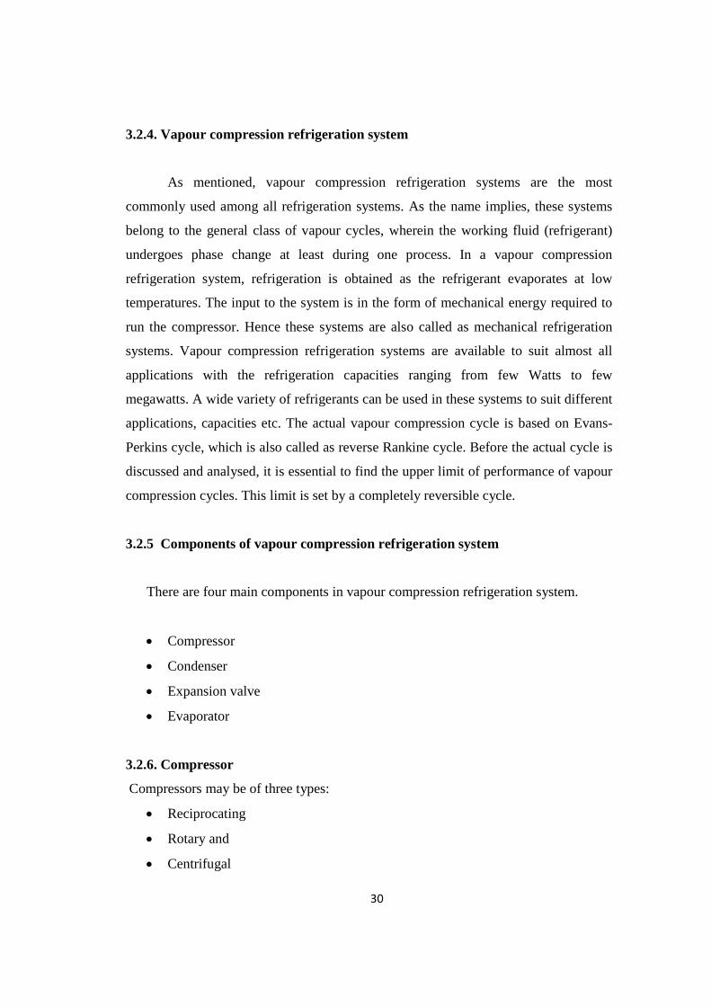
3.2.4. Vapour compression refrigeration system
As mentioned, vapour compression refrigeration systems are the most
commonly used among all refrigeration systems. As the name implies, these systems
belong to the general class of vapour cycles, wherein the working fluid (refrigerant)
undergoes phase change at least during one process. In a vapour compression
refrigeration system, refrigeration is obtained as the refrigerant evaporates at low
temperatures. The input to the system is in the form of mechanical energy required to
run the compressor. Hence these systems are also called as mechanical refrigeration
systems. Vapour compression refrigeration systems are available to suit almost all
applications with the refrigeration capacities ranging from few Watts to few
megawatts. A wide variety of refrigerants can be used in these systems to suit different
applications, capacities etc. The actual vapour compression cycle is based on Evans-
Perkins cycle, which is also called as reverse Rankine cycle. Before the actual cycle is
discussed and analysed, it is essential to find the upper limit of performance of vapour
compression cycles. This limit is set by a completely reversible cycle.
3.2.5 Components of vapour compression refrigeration system
There are four main components in vapour compression refrigeration system.
Compressor
Condenser
Expansion valve
Evaporator
3.2.6. Compressor
Compressors may be of three types:
Reciprocating
Rotary and
Centrifugal

31
When the volume flow rate of the refrigerant is large, centrifugal compressors
are used. Rotary compressors are used for small units. Reciprocating compressors are
used in plants up to 100 tones capacity. For plants of higher capacities, centrifugal
compressors are employed.
In reciprocating compressors, which may be single cylinder or multi cylinder
ones, because of clearance, leakage past the pistons and valves, and throttling effects at
the suction and discharge valves, the actual volume of gas drawn in to the cylinder is
less than the volume displaced in the system.
3.2.7. Condenser
It must de superheat and then condense the compressed refrigerant. Condensers
may be air cooled or water cooled. An air condenser is used in small units. Water
cooled condensers are used in large installations.
3.2.8. Expansion device
It reduces the pressure of the refrigerant, and also regulates the flow of the
refrigerant to the evaporator. Two widely used types of expansion devices are:
capillary tubes and throttle valves (thermostatic expansion valves).Capillary tubes are
only used for small units. Once the size and length are fixed, the evaporator pressure,
etc. gets fixed. No modifications in operating conditions are possible. Throttle valves
are used in larger units. These regulate the flow of the refrigerant according to load on
the evaporator.
3.2.9. Evaporator
A common type of evaporator is a coil brazed on to a plate, called a plate
evaporator. In a flooded evaporator the coil is filled only with a expansion coil, water
or brine may be chilled in the evaporator, and the chilled water or brine may then be
used to cool some other medium.

32
3.3. STANDARD VAPOUR COMPRESSION REFRIGERATION CYCLE
Fig.3.1. Standard vapour compression refrigeration cycle
Fig. 3.1 shows the schematic of a standard, saturated, single stage (SSS)
vapour compression refrigeration system and the operating cycle on a T-S diagram. As
shown in the Fig. the standard single stage, saturated vapour compression refrigeration
system consists of the following four processes:
Process 1-2: Isentropic compression of saturated vapour in compressor
Process 2-3: Isobaric heat rejection in condenser
Process 3-4: Isenthalpic expansion of saturated liquid in expansion device
Process 4-1: Isobaric heat extraction in the evaporator
In an ideal vapour compression refrigeration cycle, the refrigerant enters the
compression at state 1 as saturated vapour and is compressed isentropically to the
condenser pressure. The temperature of the refrigerant during this isentropic
compression process increases well above the temperature of the surrounding medium.

33
The refrigerant then enters the condenser as superheated vapour at state 2 and
leaves as saturated liquid at state3 as a result of heat rejection to the surroundings. The
temperature of the refrigerant at this state is still above the temperature of the
surroundings.
The saturated liquid refrigerant at state 3 is throttled to the evaporator pressure
by passing it through an expansion valve or capillary tube. The temperature of the
refrigerant drops below the temperature of the refrigerated space during the process.
The refrigerant enters the evaporator at state 4 as a low quality saturated mixture, and
it evaporates by absorbing heat from the refrigerated space. The refrigerant leaves the
evaporator as saturated vapour and re-enters the compressor, completing the cycle.
3.4. ANALYSIS OF VAPOUR COMPRESSION REFRIGERATION CYLCE
A simple analysis of standard vapour compression refrigeration can be carried
out by assuming a) steady flow b) negligible kinetic and potential energy changes
across each component and c) no heat transfer in connecting pipelines. The steady
flow energy equation is applied to each of the four components. The p-h diagram of
vapour compression refrigeration was shown in Fig. 3.2.
Fig.3.2. P-H diagram of vapour compression refrigeration cycle

34
Compressor
The isentropic work input to compressor (Wcs, kJ/s) is expressed as:
Wcs = mr (h2-h1) (3.1)
where h2 is the enthalpy of refrigerant at the outlet of compressor (kJ/kg)
The actual compressor work (Wc , kJ/s) is given as
Wcs = Wcs / ηs (3.2)
where ηs is the isentropic efficiency.
Condenser
The heat rejected by the condenser (Qcond , kJ/s) to the atmosphere is given as
Qcond = mr (h2 - h3) (3.3)
where h3 is the enthalpy of refrigerant at the outlet of condenser (kJ/kg)
Capillary Tube
In the capillary tube the enthalpy remains constant (isenthalpy process), therefore,
h3 = h4 (3.4)
Dossat RJ et al. (2002) measured the performance of the refrigeration cycle as coefficient
of performance (COP) and is the refrigerating effect produced per unit of work required.
It is expressed as:
COP = Qevap / Wc (3.5)
Fatouh M and El Kafafy (2006) defined the volumetric cooling capacity (VCC,
kJ/m3) as the refrigerating effect per unit volume flow rate at the inlet to the compressor.
It is expressed as
Qevap / (mr /Vs) (3.6)
where Vs is the specific volume at inlet to the compressor (m3/kg).

35
Compressor pressure ratio (pr) is given as:
pr = p dis / psuc (3.7)
where,
p dis = refrigerant vapour pressure at the compressor discharge (kN/m2)
p suc = refrigerant vapour pressure at the compressor suction (kN/m2).
3.5. REFRIGERANT R 134a
R134a is also known as Tetrafluoroethane (CF3CH2F) from the family of HFC
refrigerant. With the discovery of the damaging effect of CFCs and HCFCs refrigerants
to the ozone layer, the HFC family of refrigerant has been widely used as their
replacement.
It is now being used as a replacement for R-12 CFC refrigerant in the area of
centrifugal, rotary screw, scroll and reciprocating compressors. It is safe for normal
handling as it is non-toxic, non-flammable and non-corrosive.
Currently it is also being widely used in the air conditioning system in newer
automotive vehicles. The manufacturing industry uses it in plastic foam blowing.
Pharmaceuticals industry uses it as a propellant.
It exists in gas form when expose to the environment as the boiling temperature is
-14.9°F or -26.1°C.
This refrigerant is not 100% compatible with the lubricants and mineral-based
refrigerant currently used in R-12. Design changes to the condenser and evaporator need
to be done to use this refrigerant. The use of smaller hoses and 30% increase in control
pressure regulations also have to be done to the system.

36
Table.3.1. Properties of Refrigerant R134a
No Properties R-134a
1 Boiling Point -14.9°F or -26.1°C
2 Auto-Ignition Temperature 1418°F or 770°C
3 Ozone Depletion Level 0
4 Solubility In Water 0.11% by weight at 77°F or 25°C
5 Critical Temperature 252°F or 122°C
6 Cylinder Color Code Light Blue
7 Global Warming Potential (GWP) 1200
3.6. MAIN APPLICATIONS
Tetrafluoroethane (R134a) is a blend component for refrigeration.
It also a propellant for aerosol and a blowing agent for extruded polystyrene foams.
It replaces the CFC R12 (dichlorodifluoromethane) and in few years the HCFC R22
(chlorodifluoromethane).

37
3.7. GAS PROPERTIES
Molecular weight : 102.03 g/mol
Solid phase
Melting point (1.013 bar) : -101 °C
Liquid density (1.013 bar and 25 °C (77 °F)) : 1206 kg/m3
Boiling point (1.013 bar) : -26.55 °C
Latent heat of vaporization (1.013 bar at boiling point) : 215.9 kJ/kg
Vapor pressure (at 20 °C or 68 °F) : 5.7 bar
Vapor pressure (at 5 °C or 41 °F) : 3.5 bar
Vapor pressure (at 15 °C or 59 °F) : 4.9 bar
Vapor pressure (at 50 °C or 122 °F) : 13.2 bar
Critical temperature : 100.95 °C
Critical pressure : 40.6 bar
Critical density : 512 kg/m3
Triple point temperature : -103.3 °C
Gas density (1.013 bar at boiling point) : 5.28 kg/m3
Gas density (1.013 bar and 15 °C (59 °F)) : 4.25 kg/m3
Compressibility Factor (Z) (1.013 bar and 15 °C (59 °F)) : 1
Specific gravity : 3.25
Specific volume (1.013 bar and 15 °C (59 °F)) : 0.235 m3/ kg
Heat capacity at constant pressure (Cp) (1.013 bar and 25 °C (77 °F)) :
0.08754 kJ/(mol.K)
Solubility in water (1.013 bar and 25 °C (77 °F)) : 0.21 vol/vol

38
3.8. REFRIGERANT R152a
1,1-Difluoroethane, also DFE is an organofluorine compound with the chemical
formula C2H4F2. This colorless gas is used as a refrigerant, where it is often listed as R-
152a or HFC-152a. As an alternative to chlorofluorocarbons, it has anozone depletion
potential of zero, a lower global warming potential (120) and a shorter atmospheric
lifetime (1.4 years). It has recently been approved for use in automobile applications as
an alternative to R-134a
R152a is a colorless gas under ordinary temperature and a colorless and
transparent under the pressure of itself, easily soluble in oil but poorly in water. It is
mainly used as the important raw material in refrigerant, aerosol propellants and
synthesis of R142b. as the substitutive refrigerant for CFC-12, it will be a long term one
and have absolutely no bad effects against ozonosphere.
3.9. PROPERTIES AND CHARACTERISTICS OF R 134a AND R152a
Table.3.2. Physical, Safety and Environmental Properties Refrigerant R134a, R152a
Sl.
No.
Refrigerant R134a R152a
1. Chemical Formula CH2FCF3 CH3CHF2
2. Molecular Mass 102.03 66.05
3. Critical Temperature (0 F) 214.00 235.90
4. Critical Pressure (psia) 589.00 656.00
5. Normal Boiling Point (0 F) -15.00 -11.20
6. Lubricant POE/PAG N/A

39
7. Stability Stable Stable
8. OSHA Permissible Exposure Limit (ppm) 1000 1000
9. Lower Flammability (% Volume in Air) None 4.80
10. Heat of Combustion (Btu/lbm) 1806 7481
11. Safety Group A1 A2
12. Auto Ignition Temperature (0 F) 1418 851
13. Atmospheric Life (yr.) 14 2
14. Ozone Depletion Potential 0 0
15. Global Warming Potential (100 yr.) ** 1300 140
POE = Polyolester, PAG = Polyalkylene Glycol, * POE/PAG good candidates for R152a
Safety Group = (A or B) lower and high toxicity respectively, (1, 2, or 3) not flammable,
low and high flammability
** GWP for integrated time horizon, and based on 3500 kg CO2 / kg of R11
3.10. SUMMARY
In this chapter review of the relevant study on the vapour compression system,
the various components of the vapour compression system and its types were
presented. In addition, a detailed study on the refrigerants R134a and R152a along
with its properties and applications were discussed. This form the basis for identifying
the experimental procedures adopted in the present investigation.

40
CHAPTER 4
NANOPARTICLES AND SURFACTANTS
4.1. NANO PARTICLES
Nanoparticles and nano particle-based devices are of interest in numerous
industrial applications due to their unique and often advantageous properties. The high
surface-to-volume ratio together with size effects (quantum effects) of nanoparticles
introduces many size-dependent phenomena such as chemical, electronic, magnetic
and mechanical properties.
In nanotechnology, a particle is defined as a small object that behaves as a
whole unit with respect to its transport and properties. Particles are further classified
according to their diameter. Coarse particles cover a range between 10,000 and
2,500 nanometers. Fine particles are sized between 2,500 and 100 nanometers.
Ultrafine particles or nano particles are sized between 1 and 100 nanometers.
Nanoparticles may or may not exhibit size-related properties that differ significantly
from those observed in fine particles or bulk materials. Although the size of
most molecules would fit into the above outline, individual molecules are usually not
referred to as nanoparticles. Nano powders are agglomerates of ultrafine particles,
nanoparticles, or nano clusters. Nanometer-sized single crystals, or single-domain
ultrafine particles, are often referred to as nano crystals.
4.1.1. Properties of nano particles
Nanostructure materials are single phase or multiphase polycrystalline solids
with a typical average size of a few nanometers (1nm = 10-9m).Basically, the range
from 1-100 nm is taken as nano-range for convention as per National Nanotechnology
Initiative in the US., and the size of hydrogen atom is considered as the lower limit of
nano whereas upper limit is arbitrary. The grain sizes are so small; a significant
volume fraction of the atoms resides in grain boundaries. Material is characterized by
a large number of interfaces in which the atomic arrangements are different from those
of crystal lattice. The basic classification of nonmaterial is done based on the

41
confinement. Bulk structures show no confinement whereas nano-wells and nano
wires can be obtained by 2-D and 1-D confinement respectively. The quantum realm
comes to the picture when there is a 3D confinement and leads to zero dimension
quantum structures that is quantum dot.
4.2. SYNTHESIS METHODS OF NANO PARTICLES
Synthesis of nano material is most commonly done based on three strategies
Liquid-phase synthesis
Gas-phase synthesis
Vapour-phase synthesis
4.2.1. Liquid-phase synthesis
Under liquid phase synthesis the techniques used for synthesis are:
Co-precipitation
Sol-gel Processing
Micro-emulsions
Hydrothermal/Solvo-thermal Synthesis
Microwave Synthesis
Sono-chemical Synthesis
Template Synthesis
4.2.2. Gas-phase synthesis
Super saturation is achieved by vapourizing material into a background gas,
then cooling the gas.
4.2.3. Methods using solid precursors
Inert Gas Condensation
Pulsed Laser Ablation
Spark Discharge Generation
Ion Sputtering

42
4.2.4. Methods using liquid or vapour precursors
Chemical Vapour Synthesis
Spray Pyrolysis
Laser Pyrolysis/ Photochemical Synthesis
Thermal Plasma Synthesis
Flame Synthesis
Flame Spray Pyrolysis
Low-Temperature Reactive Synthesis
Nanostructured materials can have significantly different properties, depending
on the chosen fabrication route. Each method offers some advantages over other
techniques while suffering limitation from the others.
In attrition, macro or micro scale particles are ground in a ball mill, a
planetary ball mill, or other size reducing mechanism. The resulting particles are air
classified to recover nanoparticles. In pyrolysis, a vaporous precursor (liquid or gas) is
forced through an orifice at high pressure and burned. The resulting solid (a version of
soot) is air classified to recover oxide particles from by-product gases. Pyrolysis often
results in aggregates and agglomerates rather than single primary particles.
Thermal plasma can also deliver the energy necessary to cause vaporization of
small micrometer size particles. The thermal plasma temperatures are in the order of
10,000 K, so that solid powder easily evaporates. Nanoparticles are formed upon
cooling while exiting the plasma region. The main types of the thermal plasma torches
used to produce nanoparticles are dc plasma jet, dc arc plasma and Radio Frequency
(RF) induction plasmas. In the arc plasma reactors, the energy necessary for
evaporation and reaction is provided by an electric arc which is formed between the
anode and the cathode. For example, silica sand can be vaporized with arc plasma at
atmospheric pressure. The resulting mixture of plasma gas and silica vapour can be
rapidly cooled by quenching with oxygen, thus ensuring the quality of the fumed silica
produced.

43
In RF induction plasma torches, energy coupling to the plasma is accomplished
through the electromagnetic field generated by the induction coil. The plasma gas does
not come in contact with electrodes, thus eliminating possible sources of
contamination and allowing the operation of such plasma torches with a wide range of
gases including inert, reducing, oxidizing and other corrosive atmospheres. The
working frequency is typically between 200 kHz and 40 MHz. Laboratory units run at
power levels in the order of 30–50 kW while the large scale industrial units have been
tested at power levels up to 1 MW. As the residence time of the injected feed droplets
in the plasma is very short it is important that the droplet sizes are small enough in
order to obtain complete evaporation. The RF plasma method has been used to
synthesize different nanoparticle materials, for example synthesis of various ceramic
nanoparticles such as oxides, carbides and nitrides of Ti and Si.
Inert gas condensation is frequently used to make nanoparticles from metals
with low melting points. The metal is vaporized in a vacuum chamber and then
supercooled with an inert gas stream. The supercooled metal vapor condenses into
nanometer-sized particles, which can be entrained in the inert gas stream and deposited
on a substrate.
Nanoparticles can also be formed using radiation chemistry. Radiolysis from
gamma rays can create strongly active free radicals in solution. This relatively simple
technique uses a minimum number of chemicals. These include water, a soluble
metallic salt, a radical scavenger (often a secondary alcohol), and a surfactant (organic
capping agent). High gamma doses on the order of 104 Gray are required. In this
process, reducing radicals will drop metallic ions down to the zero-valence state. A
scavenger chemical will preferentially interact with oxidizing radicals to prevent the
re-oxidation of the metal. Once in the zero-valence state, metal atoms begin to
coalesce into particles. A chemical surfactant surrounds the particle during formation
and regulates its growth. In sufficient concentrations, the surfactant molecules stay
attached to the particle. This prevents it from dissociating or forming clusters with
other particles. Formation of nanoparticles using the radiolysis method allows for

44
tailoring of particle size and shape by adjusting precursor concentrations and gamma
dose.
4.3. ALUMINUM OXIDE (Al2O3) NANOPARTICLES
Nanoparticles are being used more and more often in research and in industry, due
to their enhanced properties compared to bulk materials. The benefits of nanoparticles
can include increased electrical conductivity, toughness and ductility, and increased
hardness and strength of metals and alloys.
This article discusses the properties and applications of aluminum oxide
nanoparticles. Aluminum is a Block P, Period 3 element, while oxygen is a Block P,
Period 2 element.
The morphology of aluminum oxide nanoparticles is spherical, and they appear as
a white powder. Aluminum oxide nanoparticles (both liquid and solid forms) are graded
as highly flammable and an irritant that can cause serious eye and respiratory irritation
4.3.1. Chemical properties
The chemical properties of aluminum oxide nanoparticles are outlined in the
following table.
Table.4.1. Chemical Properties of Al2O3
Chemical Data
Chemical symbol Al2O3
CAS No. 1344-28-1
Group Aluminum13
Oxygen 16
Electronic configuration Aluminum [Ne]3s23p1
Oxygen [He] 2s2 2p4

45
Table.4.2. Chemical Composition of Al2O3
Chemical Composition
Element Content (%)
Aluminum 52.92
Oxygen 47.04
4.3.2. Physical properties
The physical properties of aluminum oxide nanoparticles are given in the
following table.
Table.4.3. Physical Properties of Al2O3
Properties Metric Imperial
Density 3.9 g/cm3 0.140 lb/in3
Molar mass 101.96 g/mol -
4.3.3. Thermal properties
The thermal properties of aluminum oxide nanoparticles are provided in the table
below.
Table.4.4. Thermal Properties of Al2O3
Properties Metric Imperial
Melting point 2040°C 3704°F
Boiling point 2977°C 5391°F

46
4.3.4. Applications
The key applications of aluminum oxide nanoparticles are listed below:
In integrate circuit base boards
Transparent ceramics, high-pressure sodium lamps, and EP-ROM window
In YAG laser crystals
As cosmetic fillers
Single crystal, ruby, sapphire, sapphire, and yttrium aluminum garnets
High-strength aluminum oxide ceramic and C substrates
Packaging materials, cutting tools, high purity crucible, winding axle, and furnace
tubes
Polishing materials, glass products, metal products, semiconductor materials
Plastic, tape, and grinding belts
Paint, rubber, plastic wear-resistant reinforcement, and advanced waterproof
materials
Catalyst, catalyst carrier, analytical reagents
Aerospace aircraft wing leading edges
Vapor deposition materials, special glass, fluorescent materials, composite
materials and resins
In cases where aluminum oxide nanoparticles are used in the liquid form such as an
aqueous dispersion, the key applications are as follows:
Plastics, rubber, ceramics, refractory products
To improve ceramics density, smoothness, fracture toughness, creep resistance,
thermal fatigue resistance, and polymer products wear resistance
Ideal material of far infrared emission

47
4.4. COPPER OXIDE (CuO) NANOPARTICLES
Nanoparticles research is gaining increasing interest due to their unique
properties, such as increased electrical conductivity, toughness and ductility, increased
hardness and strength of metals and alloys, luminescent efficiency of semiconductors,
formability of ceramics.
This article discusses about the properties and applications of copper oxide
nanoparticles. Copper is a Block D, Period 4 element, while oxygen is a Block P, Period
2 element.
Copper oxide nanoparticles appear as a brownish-black powder. They can be
reduced to metallic copper when exposed to hydrogen or carbon monoxide under high
temperature. They are graded harmful to humans and as dangerous for the environment
with adverse effect on aquatic life.
4.4.1. Chemical properties
The chemical properties of copper oxide nanoparticles are outlined in the
following table.
Table.4.5. Chemical Properties of CuO
Chemical Data
Chemical symbol CuO
CAS No. 1317-38-0
Group Copper11
Oxygen 16
Electronic configuration Copper [Ar] 3d10 4s1
Oxygen [He] 2s2 2p4

48
Table.4.6. Chemical Composition of CuO
Chemical Composition
Element Content (%)
Copper 79.87
Oxygen 20.10
4.4.2. Physical properties
The physical properties of copper oxide nanoparticles are given in the following
table.
Table.4.7. Physical Properties of CuO
Properties Metric Imperial
Density 6.31 g/cm3 0.227 lb/in3
Molar mass 79.55 g/mol
4.4.3. Thermal properties
The thermal properties of copper oxide nanoparticles are provided in the table
below.
Table.4.8. Thermal Properties of CuO
Properties Metric Imperial
Melting point 1201°C 2194°F
Boiling point 2000°C 3632°F

49
4.4.4. Applications
The key applications of copper oxide nanoparticles are as follows:
It is used as burning rate catalyst in rocket propellant. It can greatly improve the
homogeneous propellant burning rate, lower pressure index, and also perform better
as a catalyst for the AP composite propellant
It is applied to the catalyst, superconducting materials, thermoelectric materials,
sensing materials, glass, ceramics and other fields
It is used as ceramic resistors, magnetic storage media, gas sensors, near-infrared
tilters, photoconductive and photo thermal applications
It can be used as semiconductors, solar energy transformation, and high-tech
superconductors.
4.5. ZINC OXIDE (ZnO) NANOPARTICLES
Nanotechnology research has gained momentum in the recent years by providing
innovative solutions in the field of biomedical, materials science, optics and electronics.
Nanoparticles are essentially a varied form of basic elements derived by altering their
atomic and molecular properties of elements. This article elaborates on the properties and
applications of zinc oxide nanoparticles.
Zinc oxide (ZnO) nanopowders are available as powders and dispersions. These
nanoparticles exhibit antibacterial, anti-corrosive, antifungal and UV filtering properties.
Zinc is a Block D, Period 4 element while Oxygen is a Block P, Period 2 element. Some
of the synonyms of zinc oxide nanoparticles are oxydatum, zinci oxicum, permanent
white, ketozinc and oxozinc.

50
4.5.1. Chemical properties
The chemical properties of zinc oxide nanoparticles are as per the table below.
Table.4.9. Chemical Properties of ZnO
Chemical Data
Chemical symbol ZnO
CAS No 1314-13-2
Group Zinc 12
Oxygen 16
Electronic configuration Zinc [Ar] 3d10 4s2
Oxygen [He] 2s2 2p4
Table.4.10. Chemical Composition of ZnO
Chemical Composition
Element Content (%)
Zinc 80.34
Oxygen 19.6

51
4.5.2. Physical properties
The table given below highlights the physical properties of zinc oxide
nanopowders.
Table.4.11. Physical Properties of ZnO
Properties Metric Imperial
Density 5600 kg/m3 0.202 lb/in3
Molar Mass 81.40 g/mol -
4.5.3. Thermal properties
Given below are the thermal properties of zinc oxide nanoparticles.
Table.4.12. Chemical Properties of ZnO
Properties Metric Imperial
Melting point 1975°C 3587°F
Boiling point 2360°C 4280°F
4.5.4. Applications
Some of the applications of zinc oxide nanoparticles are given below.
Zinc oxide is used in the manufacture of rubber and cigarettes (used as a filter).
Popularly known calamine lotion is made out of zinc oxide powder. It is also used
in a host of other creams and ointments that are used to treat skin diseases.
As an additive in the manufacture of concrete.
Ceramic industry has a number of uses for zinc oxide powder.

52
It is also used as an additive in food products such as breakfast cereals.
Various paints use zinc oxide as a coating agent.
4.6. CHARACTERIZATION
Nano particle characterization is necessary to establish understanding and
control of nano particle synthesis and applications. Characterization is done by using a
variety of different techniques, mainly drawn from materials science. The common
techniques are:
Electron microscopy (TEM, SEM)
Atomic force microscopy (AFM)
Dynamic light scattering(DLS)
X-ray photoelectron spectroscopy (XPS)
Powder X-ray diffraction (XRD)
Fourier transforms infrared spectroscopy (FTIR)
Matrix-assisted laser desorption/ionization time-of-flight mass
spectrometry (MALDI-TOF)
Ultraviolet-visible spectroscopy
Dual polarization interferometer
Nuclear magnetic resonance (NMR)
4.7. SURFACTANTS
Surfactant, also called surface-active agent, substance such as a detergent that,
when added to a liquid, reduces its surface tension, thereby increasing its spreading and
wetting properties. In the dyeing of textiles, surfactants help the dye penetrate the fabric
evenly. They are used to disperse aqueous suspensions of insoluble dyes and perfumes.
The surface-active molecule must be partly hydrophilic (water-soluble) and
partly lipophilic (soluble in lipids, or oils). It concentrates at the interfaces between
bodies or droplets of water and those of oil, or lipids, to act as an emulsifying agent, or
foaming agent. Other surfactants that are more lipophilic and less hydrophilic may be
used as defoaming agents, or as demulsifiers. Certain surfactants are

53
germicides, fungicides, and insecticides. Surfactants are used in corrosion inhibition, in
ore flotation, to promote oil flow in porous rocks, and to produce aerosols.
4.7.1. Properties
Surfactants reduce the surface tension of water by adsorbing at the liquid-gas
interface. They also reduce the interfacial tension between oil and water by adsorbing at
the liquid-liquid interface. Many surfactants can also assemble in the
bulk solution into aggregates. Examples of such aggregates are vesicles and micelles. The
concentration at which surfactants begin to form micelle is known as the critical micelle
concentration (CMC). When micelles form in water, their tails form a core that can
encapsulate an oil droplet, and their (ionic/polar) heads form an outer shell that maintains
favorable contact with water. When surfactants assemble in oil, the aggregate is referred
to as a reverse micelle. In a reverse micelle, the heads are in the core and the tails
maintain favorable contact with oil. Surfactants are also often classified into four primary
groups; anionic, cationic, non-ionic, and zwitterionic (dual charge).
4.7.2. Amphiphiles
The word amphiphile was coined by Paul Winsor 50 years ago. It comes from two
Greek roots. First the prefix amphi which means "double", "from both sides", "around",
as in amphitheater or amphibian. Then the root philos which expresses friendship or
affinity, as in "philanthropist" (the friend of man), "hydrophilic" (compatible with water),
or "philosopher" (the friend of wisdom or science).
An amphiphilic substance exhibits a double affinity, which can be defined from
the physico-chemical point of view as a polar-apolar duality. A typical amphiphilic
molecule consists of two parts: on the one hand a polar group which contents heteroatoms
such as O, S, P,or N, included in functional groups such as alcohol, thiol, ether, ester,
acid, sulfate, sulfonate, phosphate, amine, amide etc… On the other hand, an essentially
apolar group which is in general an hydrocarbon chain of the alkyl or alkylbenzene type,
sometimes with halogen atoms and even a few nonionized oxygen atoms.

54
The polar portion exhibits an strong affinity for polar solvents, particularly water,
and it is often called hydrophilic part or hydrophile. The apolar part is called hydrophobe
or lipophile, from Greek roots phobos (fear) and lipos (grease). The following formula
shows an amphiphilic molecule which is commonly used in shapoos (sodium dodecyl
sulfate).
4.7.3. Tension lowering agent versus surfactant
Because of its dual affinity, an amphiphilic molecule does not feel "at ease" in any
solvent, be it polar or non polar, since there is always one of the groups which "does not
like" the solvent environment. This is why amphiphilic molecules exhibit a very strong
tendency to migrate to interfaces or surfaces and to orientate so that the polar group lies
in water and the apolar group is placed out of it, and eventually in oil.
In the following the word surface will be used to designate the limit between a
condensed phase and a gas phase, whereas the term interface will be used for the
boundary between two condensed phases. This distinction is handy though not necessary,
and the two words are often used indifferently particularly in American terminology.
In English the term surfactant (short for surface-active-agent) designates a
substance which exhibits some superficial o interfacial activity. It is worth remarking that
all amhiphiles do not display such activity; in effect, only the amphiphiles with more or
less equilibrated hydrophilic and lipophilic tendencies are likely to migrate to the surface
or interface. It does not happen if the amphiphilic molecule is too hydrophilic or too
hydrophobic, in which case it stays in one of the phases.
Amphiphiles exhibit other properties than tension lowering and this is why they
are often labeled according to their main use such as: soap, detergent, wetting agent,
disperssant, emulsifier, foaming agent, bactericide, corrosion inhibitor, antistatic agent,
etc… In some cases they are konwn from the name of the structure they are able to build,
i.e. membrane, microemulsion, liquid crystal, liposome, vesicle or gel.

55
4.7.4. Classification of surfactants
Surfactants are generally classified as
i) Ionic
a) Anionic
Sodium dodecyl sulfate (SDS)
Sodium laureth sulfate (SLS)
b) Cationic
Cetyl trimethyl ammonium bromide(CTAB)
Cetyl pyridinium chloride(CPC)
c) Zwitterionic
Dodecyl betaine
Cocamido propyl betaine
ii) Non Ionic
Alkyl poly ethylene oxide
Cetyl alcohol
4.7.5. Anionic surfactants
Anionic surfactants contain anionic functional groups at their head, such
as sulfate, sulfonate,phosphate, and carboxylates. Prominent alkyl sulfates
include ammonium lauryl sulfate, sodium lauryl sulfate (SDS, sodium dodecyl sulfate,
another name for the compound) and the related alkyl-ether sulfates sodium laureth
sulfate, also known as sodium lauryl ether sulfate (SLES), and sodium myreth sulfate.

56
4.7.6. Sodium dodecyl sulphate (SDS)
Sodium dodecyl sulfate (SDS or NaDS), sodium laurilsulfate or sodium lauryl
sulfate (SLS) is an organic compound with the formula CH3(CH2)11OSO3Na. It is
an anionic surfactant used in many cleaning and hygiene products. The salt is of
an organosulfate consisting of a 12-carbon tail attached to a sulfate group, giving the
material the amphiphilic properties required of a detergent. Derived from
inexpensive coconut and palm oils, it is a common component of many domestic cleaning
products.
4.7.7. Application and properties of SDS
SDS is mainly used in detergents for laundry with many cleaning
applications. SDS is a highly effective surfactant and is used in any task requiring the
removal of oily stains and residues. For example, it is found in higher concentrations with
industrial products including engine degreasers, floor cleaners, and car wash soaps.
CMC of SDS varies with pH.
Table.4.13. Properties of Sodium Dodecyl Sulphate (SDS)
Properties
Molecular formula NaC12H25SO4
Molar mass 288.372 g/mol
Appearance white or cream-colored solid
Odor odorless
Density 1.01 g/cm³
Melting point 206 °C (403 °F; 479 K)
Refractive index (nD) 1.461

57
4.8. CATIONION SURFACTANTS
Cationic Surfactants are dissociated in water into an amphiphilic cation and an
anion, most often of the halogen type. A very large proportion of this class corresponds to
nitrogen compounds such as fatty amine salts and quaternary ammoniums, with one or
several long chain of the alkyl type, often coming from natural fatty acids. These
surfactants are in general more expensive than anionics, because of a the high pressure
hydrogenation reaction to be carried out during their synthesis. As a consequence, they
are only used in two cases in which there is no cheaper substitute, i.e. (1) as bactericide,
(2) as positively charged substance which is able to adsorb on negatively charged
substrates to produce antistatic and hydrophobant effect, often of great commercial
importance such as in corrosion inhibition.
4.8.1. Cetrimonium bromide(CTAB)
Cetrimonium bromide ((C16H33)N(CH3)3Br, cetyltrimethylammonium bromide,
hexadecyltrimethylammonium bromide, CTAB) is one of the components of the
topical antiseptic cetrimide. The cetrimonium (or hexadecyltrimethylammonium) cation
is an effective antiseptic agent against bacteria and fungi.
It is a cationic surfactant. Its uses include providing a buffer solution for
the extraction of DNA. It has been widely used in synthesis of gold nanoparticles (e.g.,
spheres, rods, bipyramids) and mesoporous silica nanoparticles (e.g., MCM-41). It is also
widely used in hair conditioning products.
As any surfactant, it forms micelles in aqueous solutions. At 303 K (30 °C) it
forms micelles with aggregation number 75-120 (depending on method of determination,
usually average ~95) and degree of ionization α (fractional charge) 0.2–0.1 (from low to
high concentration).
The standard constant of Br- counterion binding to the micelle at 303 K (30 °C)
is K° ≈ 400. This value is calculated from Br- and CTA+ ion selective
electrode measurements and conductometry data by using literature data for micelle size
(r = ~3 nm), extrapolated to the critical micelle concentration of 1 mM. However, it

58
varies with total surfactant concentration so it is extrapolated to the point at which the
concentration of micelles is zero)
The closely related compounds cetrimonium chloride and cetrimonium
stearate are also used as topic antiseptics, and may be found in many household products
such as shampoos and cosmetics, while cetrimonium bromide, due to its high cost, is only
found in select cosmetics.
4.8.2. Properties of CTAB
Table.4.14. Properties of Cetrimonium bromide
Properties
Molecular formula C19H42BrN
Molar mass 364.45 g/mol
Appearance white powder
Melting point 237–243 °C (decomposes)
4.9. ZWITTERIONIC SURFACTANTS
Zwitterionic (amphoteric) surfactants have both cationic and anionic centers
attached to the same molecule. The cationic part is based on primary, secondary, or
tertiary amines or quaternary ammonium cations. The anionic part can be more variable
and include sulfonates.
When a single surfactant molecule exhibit both anionic and cationic dissociations
it is called amphoteric or zwitterionic. This is the case of synthetic products like betaines
or sulfobetaines and natural substances such as aminoacids and phospholipids.

59
4.10. SUMMARY
A detailed study and analysis and nano particles, their properties, synthesis and
techniques were presented in this chapter. Understanding of physical, chemical and
thermal properties enables to choose the suitable nano particles for the present work. In
addition to this a detailed investigation on surfactants and its types with their properties
was also present in this chapter.

60
CHAPTER 5
EXPERIMENTAL SETUP AND PREPARATION OF THE
NANOFLUIDS
5.1. FABRICATION OF EXPERIMENTAL SETUP
The experimental consists of a compressor, fan cooled condenser, expansion
device and an evaporator section. Capillary tube is used as an expansion device. The
evaporator is of serpentine coil type which is loaded with water. Service ports are
provided at the inlet of expansion device and compressor for charging the refrigerant. The
mass flow rate is measured with the help of flow meter fitted in the line between
expansion device and drier unit. The experimental setup was placed on a platform in a
constant room temperature. The ambient temperature was ±1.5°C. The air flow velocity
was found to be less than 0.25m/s.
Fig.5.1. Photograph of the experimental setup

61
5.2. MEASUREMENT OF PARAMETERS
The temperatures at different parts of the experimental setup are measured using
resistance thermocouples. 8 numbers of resistance thermocouples were used for the
experimentation. The pressure at compressor suction, discharge, condenser outlet and at
evaporator outlet are measured with the help of pressure gauges. The power consumption
of the system was measures by a digital Watt-hr meter. A digital wattmeter and flow
meter were also connected with the experimental setup. Table.5.1. summarized the
characteristics of the instrumentation.
Table.5.1. Measurement equipments
Fig.5.2. Schematic representation of the experimental setup
Variable Device Range
Temperature Pt100 PID controller -50 to 199°C
Pressure Pressure Gauge 0-10 bar
Power Digital Watt/Watt-h meter 5-20A

62
5.3. MOUNTING OF THERMOCOUPLES
Refrigeration test rig was developed in order to investigate the performance of
the system. In developing the reliable refrigerator test rig, consideration should be highly
addressed especially the development method and measurement locations of pressure
and temperature. These are very important to ensure that the test rig can produce reliable
data. Pannock, J et al. (1994), Philipp, J et al. (1996), Mc Keller and Tree, D.R (1988)
and Melo, C and Pereira, R. H (1988) discussed the development of refrigerator test rig.
They discussed the locations of temperature and pressure measurement points,
measurement devices and measurement methods. There are eight points of temperature
measurement, four points of pressure measurement and one point of flow rate
measurement.
From the eight points of temperature measurement, six points have been placed in
the refrigeration circuit to measure refrigerant temperature and another two points have
been placed in the evaporator compartment. The same number of points and
locations were adopted by Pannock, J et al. (1994), Philipp, J et al. (1996), Mc keller
and Tree, D.R (1988) and Melo, C and Pereira, R. H (1988) who followed several
standards such as ANSI/AHAM HRF-1988 (AHAM 1988) and European standard for
measuring the energy consumption of electric mains operated on household refrigerators
(DIN EN 153). The thermocouple wire was used to measure the temperature of
refrigerant in the tube (ANSI/ASHRAE Standard, 1986). The technique to measure the
temperature is the same as Philipp et al (1996), where the thermocouple wire was put
inside the refrigerant tube so that the measurement made was exactly the temperature of
the refrigerant. However, the method to construct the sensor was different. Fig 3 shows
the method to construct the temperature measurement point in the refrigerant tube.
By using this method, A suitable length of copper tube with flared end was used
to hold a thermocouple wire which was inserted into the tube and effectively sealed.
The flared tube is fitted securely on to a copper T-junction which was then joined
mechanically to the tube to reconnect every two consecutive components. The
temperature of the refrigerant which now flowed through each T-junction was measured

63
by the hot thermocouple junction or head. Prior to installation each thermocouple was
calibrated using a platinum thermocouple against temperature of freezing point, room
condition and boiling point of water. Table 1 shows the three sets of data with different
conditions of water used during calibration. The thermocouple used was of T-type,
0.3 mm diameter and designed for temperature range between -50°C to 250°C. The
accuracy is about ±2%.
Fig 5.3. Construction method of temperature measurement point

64
Table.5.2: Calibration data of thermocouple points
Thermocouple Temperature MeasurementType / No. Freezing Room Boiling
Platinum 0°C 20.1 °C 99.4 °CNo. 1 -0.3°C 20.1 °C 99.1 °CNo. 2 -0.2°C 19.9 °C 99.3 °CNo. 3 -0.2°C 20.0 °C 99.2 °CNo. 4 -0.2°C 20.1 °C 99.2 °CNo. 5 -0.2°C 20.0 °C 99.1 °CNo. 6 0°C 20.1 °C 99.1 °CNo. 7 -0.1°C 20.0 °C 99.2 °CNo. 8 -0.1°C 20.1 °C 99.1 °C
Besides that, four points of pressure were tapped respectively made on pipes
connecting all main components. Experimental works of Pannock, J et al. (1994),
Philipp, J et al. (1996), and Melo, C and Pereira, R. H (1988) only measured suction and
discharge pressures of compressor while the present works allowed pressure drops
across each component and along connecting pipes to be known (Jones, 2001,
ASHRAE, 2001). Bourdon Tube pressure gauges were used for each pressure
measurement in this test rig (ANSI/ASHRAE Standard, 1989, ARI 1998). A tube with
diameter 2.1 mm was used to connect the refrigerant tube to each pressure gauge as
what was done by Philipp. Fig 4 shows the detail construction of the pressure
measurement points.

65
Fig 5.4. Assembly method of pressure measurement using Bourdon type pressure
Gauge
In this work a metal tube flow meter indicator was used. This flow meter was
manufactured and calibrated by Brooks Instruments. The flow meter was assembled
between condenser and capillary tube to measure the refrigerant flow rate in liquid
form in g/s. A sight glass was installed before the flow meter to observe the liquid
phase of the refrigerant. When there were no bubbles observed the flow was taken as
that of a fully liquid refrigerant (Eugene, 2002, Jones, 2001).
5.4. LEAK PROOF TESTING AND CHARGING OF EXPERIMENTAL SETUP
The fabricated experimental setup was filled with N2 gas at a pressure of 5 to 7
bar and this pressure is maintained for 5 hrs. Thus the system was ensured for no
leakages. The system was evacuated by removing N2 gas. A vacuum pump was
connected to the port provided in the compressor and the system was completely

66
evacuated for the removal of any impurities. This process was carried out for all the
trials. The refrigerant R152a was charged through the charging line to the compressor.
Precision electronic balance with accuracy ±1% was used to charge into the system.
Every time the system was allowed to stabilize for 10 min.
5.5. PREPARATION AND CHARACTERIZATION OF NANO FLUIDS
5.5.1 Equipments used for characterization of nano fluids
The equipments which were used for characterization of nano fluids are SEM, EDXS,
XRD and KD2 Pro thermal analyzer.
5.5.2. Scanning electron microscope (SEM)
A scanning electron microscope (SEM) as shown in Fig 5.5 is a type of electron
microscope that produces the images of a sample by scanning it with a focused beam of
electrons. The electrons interact with electrons in the sample, producing various signals
that can be detected and that contain information about the sample's
surface topography and composition. The electron beam is generally scanned in a raster
scan pattern, and the beam's position is combined with the detected signal to produce an
image. SEM can achieve resolution better than 1 nanometer. Specimens can be observed
in high vacuum, low vacuum and environmental SEM specimens can be observed in wet
conditions.
The types of signals produced by a SEM include secondary electrons (SE), back-
scattered electrons (BSE), characteristic X-rays, light (cathode luminescence) (CL),
specimen current and transmitted electrons. The SEM can produce very high-resolution
images of a sample surface, revealing details less than 1 nm in size. A wide range of
magnifications is possible, from about 10 times (about equivalent to that of a powerful
hand-lens) to more than 500,000 times, about 250 times the magnification limit of the
best light microscopes.

67
In a typical SEM, an electron beam is thermionically emitted from an electron
gun fitted with a tungsten filament cathode. Tungsten is normally used in thermionic
electron guns because it has the highest melting point and lowest vapour pressure of all
metals, thereby allowing it to be heated for electron emission, and because of its low cost.
Other types of electron emitters include lanthanum hexaboride (LaB6) cathodes, which
can be used in a standard tungsten filament SEM if the vacuum system is upgraded and
FEG, which may be of the cold-cathode type using tungsten single crystal emitters or the
thermally assisted Schottky type, using emitters of zirconium oxide.
Fig. 5.5. Scanning electron microscope
The electron beam, which typically has an energy ranging from 0.2 keV to 40 keV, is
focused by one or two condenser lenses to a spot about 0.4 nm to 5 nm in diameter. The
beam passes through pairs of scanning coils or pairs of deflector plates in the electron
column, typically in the final lens, which deflect the beam in the x and y axes so that it
scans in a faster fashion over a rectangular area of the sample surface.
When the primary electron beam interacts with the sample, the electrons lose energy
by repeated random scattering and absorption within a tear drop-shaped volume of the
specimen known as the interaction volume, which extends from less than 100 nm to
around 5 µm into the surface. The SEM used in this study is of Make: Hitachi, Model:
S-3400N, resolution: 3nm@30kV and magnification: 5X to 300,000X.

68
5.6. ENERGY-DISPERSIVE X-RAY SPECTROSCOPY (EDXS)
Energy-dispersive X-ray spectroscopy (EDXS) is an analytical technique which is
used for the elemental analysis or chemical characterization of a sample. It relies on the
investigation of an interaction of some source of X-ray excitation and a sample. The
intensity or area of a peak in an EDX spectrum is proportional to the concentration of the
corresponding element in the specimen. For determining elemental content, the electron-
beam current is assumed to be uniform throughout the specimen and electron channeling
is avoided by avoiding strong diffraction conditions. Energy Dispersive X-ray Analysis
(EDXA) technique is used for performing chemical analysis in conjunction with
Scanning Electron Microscopy (SEM) and Transmission Electron Microscopy (TEM).It
is not a surface science technique. The analytical data is acquired in the form of digitized
spectra, viewed during accumulation on a computer monitor, which displays the number
of X-rays, I, detected as a function of E, the X-ray energy.
An electron beam strikes the surface of conducting sample (SEM) .The energy of the
beam is typically in the range of 10-20 keV. This causes X-rays to be emitted from the
irradiated material. The energy of the X-rays emitted depends on the material under
examination. The X-rays are generated in a region about 2 microns in depth (SEM), and
thus EDX is not a surface science technique. By moving the electron beam across the
material and 2-D (two dimensional) image of each element in the sample can be acquired.
Due to the low X-ray intensity, images usually take a number of hours to be acquired.
Elements of low atomic number are difficult to detect by EDX. A Beryllium window is
often used to protect the SiLi detector in the EDX system. The absorption of the soft X-
rays precludes the detection of elements below an atomic number of 11 (Na). In
windowless EDX systems, elements with as low atomic number as 4 (Be) have been
detected, but the problems involved get progressively worse as the atomic number is
reduced.

69
5.6.1. X-Ray diffractometer
An X-ray diffractometer illuminates a sample of material with X-rays of known
wavelength, moving the sample and detector in order to measure the intensity of the
diffracted radiation as a function of beam and sample orientation. From the resulting
intensity versus angle plot much can be inferred about the structure of the material. A
diffractometer can be used to make a diffraction pattern of any crystalline solid. With a
diffraction pattern an investigator can identify an unknown mineral, or characterize the
atomic-scale structure of an already identified mineral.
Diffraction occurs as waves interact with a regular structure whose repeat distance is
about the same as the wavelength. The phenomenon is common in the natural world, and
occurs across a broad range of scales. For example, light can be diffracted by a grating
having scribed lines spaced on the order of a few thousand angstroms, about the
wavelength of light. It happens that X-rays have wavelengths on the order of a few
angstroms, the same as typical interatomic distances in crystalline solids. That means X-
rays can be diffracted from minerals which, by definition, are crystalline and have
regularly repeating atomic structures.
5.6.2. X-RAY DIFFRACTION TECHNIQUE
Fig.5.6. X-ray Diffraction principle in accordance with Bragg’s Law

70
Until 1895 the study of matter at the atomic level was a difficult task but the
discovery of electromagnetic radiation with 1 Å (10-10 m) wavelength, appearing at
the region between gamma-rays and ultraviolet, makes it possible. As the atomic
distance in matter is comparable with the wavelength of X-ray, the phenomenon of
diffraction find its way through it and gives many promising results related to the
crystalline structure. The unit cell and lattices which are distributed in a regular three-
dimensional way in space forms the base for diffraction pattern to occur. These lattices
form a series of parallel planes with its own specific d-spacing and with different
orientations exist. The reflection of incident monochromatic X-ray from successive
planes of crystal lattices when the difference between the planes is of complete
number n of wavelengths leads to famous Bragg’s law:
n λ = 2dsin θ
Where n is an integer 1, 2, 3….. (Usually equal 1), λ is wavelength in
angstroms (1.54 Å for copper), d is inter atomic spacing in angstroms, and θ is the
diffraction angle in degrees. Plotting the angular positions and intensities of the
resultant diffracted peaks of radiation produces a pattern, which is characteristic of the
sample. The fingerprint characterization of crystalline materials and the determination
of their structure are the two fields where XRD has been mostly used. Unique
characteristic X-ray diffraction pattern of each crystalline solid gives the designation
of “fingerprint technique” to XRD for its identification. XRD may be used to
determine its structure, i.e. how the atoms pack together in the crystalline state and
what the interatomic distance and angle are etc. From these points it can be concluded
that X-ray diffraction has become a very important and powerful tool for the structural
characterization in solid state physics and materials science.

71
.
Fig. 5.7 Analytical X’Pert PRO diffractometer
The crystal size of the particle is calculated using the Debye-Scherrer formula as
shown in equation 5.1.
Where D is the size of the particle, λ is the X-ray wavelength (1.5406), β is the peak
width and theta is the Braggs angle.
5.7. KD2 Pro thermal analyser
The KD2 Pro is a battery-operated, menu-driven device. It consists of a handheld
microcontroller and sensor needles. The KD2’s sensor needle contains both a heating
element and a thermistor. The controller module contains a battery, a 16-bit
microcontroller/AD converter, and power control circuit. The thermal conductivity
measurement assumes: (i) the long heat source can be treated as an infinitely long heat
source (ii) the medium is both homogeneous and isotropic, and at uniform initial
temperature, T0. The sensor needle used is KS-1 which is made of stainless steel having a
length of 60 mm and a diameter of 1.3 mm, and closely approximates the infinite line
heat source which gives least disturbance to the sample during measurements. The sensor

72
needle can be used for measuring thermal conductivity of fluids in the range of 0.2–2
W/mK with an accuracy of ±5%.
Fig 5.8. KD2 Pro thermal analyzer
Each measurement cycle consists of 90s. During the first 30 s, the instrument will
equilibrate which is then followed by heating and cooling of sensor needle for 30 s each.
At the end of the cycle, the controller computes the thermal conductivity using the
change in temperature (∆T) – time data from equation 5.2.
Where q is constant heat rate applied to an infinitely long and small line source, ∆T1 and
∆T2 are the changes in the temperature at times t1 and t2 respectively.
The KD2 analyzer used in our experiments collects data at 1 s intervals during a 30 s
heating time and a 30 s cooling time. The final 20 points during heating and cooling are
used in a simultaneous least squares computation which determines the thermal
conductivity. Temperature is measured by a 16 bit analog to digital converter. All of the
computations are done by an internal 16 bit microcontroller, and the result is displayed.
The calibration of the sensor needle is carried out first by measuring thermal conductivity
of distilled water and glycerine. The measured values for distilled water and glycerin are

73
0.611 and 0.292 W/mK respectively which are in agreement with the literature values of
0.613 and 0.285 W/mK respectively within ±5% accuracy (Hagen 1999, Vargaftik 1975,
Kothandaraman 2007). The calibration of the KD2 Pro sensor needle is carried out at
room temperature (320C) and the uncertainty in measurements is calculated as ±2% on
the basis of 95% confidence level.
5.8. SYNTHESIS OF NANOFLUID
Preparation of nano fluids is the first key step in experimental studies with nano
fluids. Nano fluids are not just dispersion of solid particles in a fluid. The essential
requirements that a nano fluid must fulfill are even and stable suspension, adequate
durability, negligible agglomeration of particles, no chemical change of the particles or
fluid, etc. Nanofluids are produced by dispersing nanometer scale solid particles into base
liquids such as water, ethylene glycol, oil, etc. In the synthesis of nano fluids,
agglomeration is a major problem.
5.8.1. Two step method synthesis of nanofluids
The two-step method is extensively used in the synthesis of nano fluids
considering the available commercial nano-powders supplied by several companies. In
this method, nanoparticles were first produced and then dispersed in the base fluids.
Generally, ultrasonic equipment is used to intensively disperse the particles and reduce
the agglomeration of particles. As compared to the single-step method, the two-step
technique works well for oxide nanoparticles, while it is less successful with metallic
particles. Except for the use of ultrasonic equipment, some other techniques such as
control of pH or addition of surface active agents are also used to attain stability of the
suspension of the nano fluids against sedimentation. These methods change the surface
properties of the suspended particles and thus suppress the tendency to form particle
clusters. In this work two step method was incorporated for the preparation of the
nano-fluids (nano lubricants).

74
5.8.2. Critical issues involved in and after nano fluid synthesis
The inherent difficulties associated with characterizing the particle size and
dispersion characteristics of nano fluids further complicate the study of heat transport
in these suspensions. The nanometer-scale of the particle additions dramatically limits
the options available for sample characterization. Electron microscopy techniques are
by far the most commonly available methods to image nano-size objects. Traditional
electron microscopes, however, require a nano fluid sample to be dried before it can be
imaged in a vacuum. Therefore, additional agglomeration resulting from the drying
process (as well as clumping structures that might be destroyed in the process) would
tend to render the results as non-representative. In addition, the resulting images also
represent a very small snapshot of the fluid, and therefore, many carefully chosen
samples are required to ensure data is representative of the entire sample. Alternative
methods include “wet-cell” electron microscopy where images are taken of samples
that remain in solution, small angle x-ray diffraction scattering (SAXS), and dynamic
light scattering (DLS). The latter two options are particularly attractive because they
can provide full particle size distribution data that is representative of the entire
sample. Although, for SAXS some concerns include an upper cut off on detectable
size and possible interaction effects.
During sonication, bubbles are created and collapsed, and the resulting shock
from this cavitation process breaks up nano particles agglomerates. However, the
process also generates heat and the nano fluid temperature rises, especially in
continuous mode sonication. In order to mitigate evaporation of the base fluid during
sonication, a cooling system should be employed during the continuous mode
sonication.
The lack of nano particle dispersion within nano fluids appears to be a limiting
factor in the effectiveness of their heat transfer. Agglomeration issues must be
overcome in order to obtain the full potential of nano fluid heat transfer.
Agglomeration and size characterization issues are current limitations to the usefulness
and understanding of nano fluids.

75
The preparation of the nano fluid in our project involved three phases. They are as
follows.
5.9. HOMOGENISING OF NANO PARTICLES IN THE LUBRICANT
Three lubricants bottles of Sanden SP-10 lubricant was taken 250 ml in each
beaker. The nano particles CuO of 0.05%v was taken and added to one of the beaker
containing the lubricant. The same procedure was followed for the rest of the two ZnO
and Al2O3 samples. It is manually stirred first and then closed tightly with a cap and
shaken properly to get it mixed well.
Fig.5.9. Mixing of Nano particles of Al2O3, ZnO and CuO
5.9.1. Magnetic stirring
A magnetic stirrer or magnetic mixer is a laboratory device that employs a
rotating magnetic field to cause a stir bar immersed in a liquid to spin very quickly,
thus stirring it. The rotating field may be created either by a rotating magnet or a set of
stationary electromagnets, placed beneath the vessel with the liquid. A stir bar is
the magnetic bar placed within the liquid which provides the stirring action. The stir
bar's motion is driven by another rotating magnet or assembly of electromagnets in the
stirrer device, beneath the vessel containing the liquid.

76
Fig.5.10.Magnetic stirring process of Al2O3, ZnO and CuO nano particles
They are bar shaped and often octagonal in cross-section (sometimes circular),
although a variety of special shapes exist for more efficient stirring. Most stir bars
have a ridge around the center (called a pivot ring) on which they rotate. Magnetic
stirring was done for 6 hours for each sample of the nano fluid sample that was
prepared earlier.
5.9.2. Ultrasonication
Ultrasonication process is done by an ultrasonic bath. An ultrasonic bath is a
high frequency electrical energy that is converted into ultrasound waves by means of
ultrasonic transducers, which are bonded on the base of S.S. water tank. The ultrasonic
bath sonicator are high frequency sound waves that are created in the liquid countless,
microscopic vacuum bubbles, which rapidly expand & collapse. This phenomenon is
cavitation. The bubbles act like miniature high speed brushes, driving the liquid into
all openings and minutes recesses of the object immersed in the liquid.
Fig.5.11. Ultrasonication process of Al2O3, ZnO and CuO Nano particles

77
Ultrasonic baths can be used for cleaning or indirect contact homogenization.
The high frequency sound waves provide the necessary action for the homogenization
and the uniform agglomeration of the nano particles in the lubricant.
Fig.5.12. Synthesized Nano lubricants of Al2O3, ZnO and CuO with no particle
settlement
Nano fluid samples thus prepared are kept for observation and no particle
settlement was observed at the bottom of the flask containing nano fluids even after 24
hours. Thus Nano lubricants with Alumina, Zinc oxide, Copper oxide were
synthesized by Magnetic stirring and Ultrasonication process
5.10. CHARACTERIZATION OF COPPER OXIDE NANOFLUID
The characterization of copper oxide nanoparticles were done by XRD for
structural determination and estimation of crystalline size using the instrument
PAnalytical X’Pert PRO diffractometer and the average size of the nanoparticle were
calculated using Debye-Scherrer equation 5.1 and it was 50 nm and image for XRD is
shown in Fig 5.13
Scanning Electron Microscope and Energy Dispersive X-ray Analysis (EDXA) is
done using the instrument Hitachi, model: S-3400 N for surface morphology and
chemical analysis. The result showed that the copper oxide nanoparticle is spherical in
shape and the presence Cu and O elements are confirmed Fig 5.16 shows the image of

78
dispersed copper oxide nanoparticle in base fluid and the thermal conductivity is
measured using KD2 Pro thermal analyzer, Decagon Devices, Inc., USA. The value is
found to be 0.698 W/mK and showed an increase of 12.4 % when compared to DI Water
(0.613 W/mK).
.
Fig 5.13. X-ray diffractogram for the copper oxide nanoparticles
Fig.5.14.SEM Micrograph (5000X) of CuO nanoparticles

79
Fig.5.15. EDX diffractogram of CuO nanoparticles
Fig 5.16. SEM image for copper oxide nanofluid

80
5.11. CHARACTERIZATION OF ALUMINIUM OXIDE NANOFLUID
The characterization of Aluminium oxide nanoparticles were done by XRD, SEM,
EDXA and KD2 Pro thermal analyzer. Using the instrument PAnalytical X’Pert PRO
diffractometer the structural determination and estimation of crystalline size were carried
out. The average size of the nanoparticle was calculated using Debye-Scherrer equation
5.1 and it was 50 nm. The image for XRD is shown in Fig 5.17.
Scanning electron microscope and energy dispersive X-ray analysis (EDXA) is done
using the instrument Hitachi, model: S-3400 N for surface morphology and chemical
analysis. The result showed that the aluminum oxide nanoparticle is spherical in shape is
shown in Fig 5.19 and the presence of Al and O elements are confirmed. Fig 5.20 shows
the image of dispersed aluminum oxide nanoparticle in base fluid and the thermal
conductivity is measured using KD2 Pro thermal analyzer, Decagon Devices, Inc., USA.
The value is found to be 0.6507W/mK which showed an increase of 5.8 % when
compared to DI Water (0.613 W/mK).
Fig.5.17. X- Ray diffraction pattern of Al2O3

81
Fig.5.18. SEM Micrograph (5000X) of Al2O3 Nanoparticles
Fig.5.19. EDX diffractogram of Al2O3 nanoparticles

82
Fig 5.20. SEM image of Al2O3 nanofluid
5.12. CHARACTERIZATION OF ZINC OXIDE NANOFLUID
The characterization of Zinc oxide nanoparticles were done by XRD, SEM, EDXA
and KD2 Pro thermal analyzer. Using the instrument PAnalytical X’Pert PRO
diffractometer the structural determination and estimation of crystalline size were carried
out. The average size of the nanoparticle was calculated using Debye-Scherrer equation
5.1 and it was 50 nm. The image for XRD is shown in Fig 5.21.
Scanning electron microscope and energy dispersive X-ray analysis (EDXA) is done
using the instrument Hitachi, model: S-3400 N for surface morphology and chemical
analysis. The result showed that the zinc oxide nanoparticle is spherical in shape. The
presence of Zn and O elements are confirmed. The thermal conductivity is measured
using KD2 Pro thermal analyzer, Decagon Devices, Inc., USA. The value is found to be
0.601W/mK which showed an increase of 2.3% when compared to DI Water (0.613
W/mK).

83
Fig.5.21. X- Ray diffraction pattern of ZnO
Fig.5.22. SEM micrograph of (5000X) ZnO nanoparticles

84
Fig.5.23. EDX diffractogram of ZnO nanoparticles
5.13. SUMMARY
In this chapter the fabrication of the experimental setup and mounting of pressure
gauges and thermo couples on the system were present. The preparation methodology
and characterization techniques for nano fluids along with the critical issues were
discussed in detail.

85
CHAPTER 6
BLENDING OF R152a AND R134a
6.1. INTRODUCTION
This chapter deals with the experimental procedure adopted, relevant parameters
during the course of the present investigation. In developing country like India, most of
the vapour compression based refrigeration, air conditioning and heat pump systems
continue to run on halogenated refrigerants due to its excellent thermodynamic and
thermo-physical properties apart from the low cost. However, the halogenated
refrigerants have adverse environmental impacts such as ozone depletion potential (ODP)
and global warming potential (GWP). Hence it is necessary to look for alternatives
refrigerants to full fill the objectives of the international protocols (Montreal and Kyoto)
and to satisfy the growing worldwide demand.
6.2. BLENDING OF R152a AND R134a
The system was charged with the help of charging system and evacuated with the
help of vacuum pump to remove the moisture. After charging each refrigerant, data were
collected and different evaporator temperatures using equation 3.1 to 3.7. The following
parameters were obtained using the above equations. a) vapour pressure b) compressor
input power c) co-efficient of performance d) volumetric cooling capacity and e) pressure
ratio. Initially a performance test is made with the system loaded with pure R134a. The
data is treated as the basis for the comparison with the refrigerant mixtures. The mixture
composed of R152a and R134a was considered as an alternative to R134a. This mixture
is further referred in this work as HCM. Blend mixtures HCM of R152a and R134a by
mass in the proportion of HCM 30:70 (30% weight of R152a and 70% weight of R134a),
HCM 50:50 (50% weight of R152a and 50% weight of R134a) and HCM 70:30 (70%
weight of R152a and 30% weight of R134a) were charged through the charging port in
the compressor and the performance tests were conducted. The results of the performance
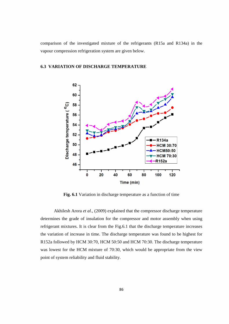
86
comparison of the investigated mixture of the refrigerants (R15a and R134a) in the
vapour compression refrigeration system are given below.
6.3 VARIATION OF DISCHARGE TEMPERATURE
Fig. 6.1 Variation in discharge temperature as a function of time
Akhilesh Arora et al., (2009) explained that the compressor discharge temperature
determines the grade of insulation for the compressor and motor assembly when using
refrigerant mixtures. It is clear from the Fig.6.1 that the discharge temperature increases
the variation of increase in time. The discharge temperature was found to be highest for
R152a followed by HCM 30:70, HCM 50:50 and HCM 70:30. The discharge temperature
was lowest for the HCM mixture of 70:30, which would be appropriate from the view
point of system reliability and fluid stability.

87
6.4. VARIATION OF DISCHARGE PRESSURE
Fig. 6.2 Variation in discharge pressure as a function of time
Fig.6.2 shows that the discharge pressure decreases with the variation in time. The
discharge pressure was recorded to be highest for R152a followed by HCM 70:30, HCM
50:50 and HCM 70:30. The discharge pressure was found to be lowest for pure R134a.

88
6.5. EFFECT OF EVAPORATOR TEMPERATURE ON VAPOUR PRESSURE
OF THE REFRIGERANTS
Fig. 6.3 Variation of vapour pressure with varying evaporator temperature for R152a,
HCM mixtures and R134a
The variation of saturation pressure of a function of evaporator temperature for three
refrigerant mixtures is shown in Fig.6.3. R152a as lowest pressure and R134a recorded
the highest pressure. The HCM 70:30 recorded the lowest pressure among the three
mixtures. Refrigerant with low pressure is desirable in the system because the higher the
pressure the heavier must be the equipment parts and accessories. Usage of R152a owing
to the lowest vapour pressure reduces the heaviness of the various components of the
refrigeration system.

89
6.6. VARIATION OF PRESSURE RATIO
Fig. 6.4 Variation of pressure ratio with varying evaporator temperature for R152a,
HCM mixtures and R134a
Pressure ratio is the ratio between outlet pressure and inlet pressure of the compressor
unit. Fig.6.4 shows the variation of the pressure ratio with varying evaporator
temperature for R152a, HCM mixtures and R134a. It is evident from the Fig. that
pressure ratio decreases with increase in evaporator temperature. The trends are similar
for the three HCM mixtures. The average pressure ratio for HCM 70:30 was lowest
among the three HCM mixtures. The pressure ratio is less the compressor can be a lighter
one. The same compressor can be used for the HCM mixtures.

90
6.7. VARIATION OF COMPRESSOR INPUT POWER
Fig. 6.5 Variation of Compressor input power with varying evaporator temperature for
R152a, HCM mixtures and R134a
The changes of compressor input power with evaporator temperature are illustrated in
Fig.6.5, which reviews that the compressor input power increases as the evaporator
temperature increases. The power consumption the compressor was found to be lesser for
HCM 70:30 among the three HCM mixtures.

91
6.8. DIFFERENCE IN EVAPORATOR TEMPERATURE
Fig. 6.6 Variation of evaporator with varying time
The difference in evaporator temperature was found to be in increasing trend for all the
HCM mixtures with increase in time. Among the mixtures HCM 70:30 shows the highest
difference in temperature which shows the higher removal of heat from the evaporator
unit. The temperature difference was highest for R152a. as shown in Fig. 6.6.

92
6.9. EFFECT OF EVAPORATOR TEMPERATURE ON VCC
Fig. 6.7 Variation of volumetric cooling capacity with varying evaporator temperature
for R152a, HCM mixtures and R134a
Volumetric cooling capacity (VCC) is the refrigerating effect per unit volume
fluoride and the inlet of the compressor (B.O. Bolaji, 2011). Fig.6.7 shows the volumetric
cooling capacity with varying evaporator temperature for the three HCM mixtures. The
VCC increases with increase in evaporator temperature. This is due to increase in cooling
effect and decrease in specific volume, which means that the higher the VCC the smaller
as the size of the compressor required. Out of the three HCM mixtures, HCM 70:30 has
got higher volumetric cooling capacity. Hence a smaller size of compressor is sufficient
for HCM 70:30 when compared to pure R134a.

93
6.10. INFLUENCE OF HCM MIXTURE ON COP
Fig. 6.8 Variation of COP with varying refrigerant composition
By the first law of thermo dynamics, the measure of performance of the refrigeration
cycle is the co-efficient of performance (COP). It is the refrigerating effect produced per
unit of work required (B.O. Bolaji, 2011). Fig.6.8 shows the variation of COP for
various HCM mixtures. Among the three mixtures HCM 70:30 as the highest COP. The
lowest COP among the mixtures was as shown by HCM 30:70.

94
6.11. SUMMARY
In this chapter the performance of three HCM mixtures in the vapour compression
refrigeration system were investigated experimentally and compared. Out of the three
HCM mixtures, HCM 70:30 offers desirable characteristics such as low operating
temperature and pressure, high volumetric cooling capacity and high co-efficient of
performance.

95
CHAPTER 7
NANOADDITIVES IN R152A REFRIGERANT
7.1 INTRODUCTION
The rapid advances in nanotechnology have lead to emerging of new generation
heat transfer fluids called as nanofluids. Suspending nano sized particles (1-100 nm) in
the conventional fluids possess higher thermal conductivity than the base fluid. This
concept is being adopted in the work of suspending nanoparticles in the refrigerant
R152a. R152a refrigerant is a nature friendly used in refrigeration system. The
thermophysical properties and convective heat transfer nature of refrigerant determines
the performance of refrigeration equipments such as domestic refrigerators and air
conditioners. The addition of nanoparticles to the refrigerant results in the improvement
of thermophysical properties and heat transfer characteristics of the refrigerant thereby
the performance of the system could be improved to a large extent (N.Subramani et al.,
2011).
7.2 NANOADDITIVE IN VAPOUR COMPRESSION REFRIGERATION
SYSTEM
Nanoparticles can be used in refrigeration system because of its remarkable
improvement in thermophysical and heat transfer capabilities to enhance the performance
of the refrigeration system. In a vapour compression refrigeration system the
nanoparticles can be added to the lubricant oil in the compressor. When the refrigerant is
circulated through the compressor it carries traces of lubricant and nanoparticles mixture
(nanolubricant) so that the other heat transfer components will have nanolubricant-
refrigerant mixture.
Some investigators have conducted studies on the effect of nanoparticles in the
refrigerant / lubricant on the system performance. Bi et al. (2011) conducted an
experimental study on the performance of a domestic refrigerator using TiO2 – R600a
nanorefrigerant as working fluid. They reported that the system worked safely and

96
efficiently with an energy saving of 9.6%. They also cited that the freezing velocity of
nano-refrigerating system was more than that of pure R600a system.
Bi et al. (2007) conducted studies on the domestic refrigerator using
nanorefrigerant. In their studies they used R134a as the refrigerant. TiO2 nanoparticles
were suspended in the mineral oil of the compressor unit. It was reported that the
refrigeration system worked safely without any system modification and the energy
consumption reduces by 21.2%.
Jwo (2009) conducted studies on a refrigeration system replacing R134a
refrigerant and polyester lubricant with a hydrocarbon refrigerant and mineral refrigerant.
The mineral oil included added Al2O3 nanoparticles to improve the lubrication and heat
transfer performance. Their study explained that 60% R134a and 0.1% wt Al2O3
nanoparticles were optimal. The power consumption was reduced by 2.4% and the
coefficient of performance was increased by 4.4%.
From literature, oxide nanoparticles of concentrations less than 0.5%v have
shown proven enhanced thermal conductivity than the base fluids. Higher concentration
of oxide nanoparticles turns to be more of insulator. Hence the concentration of nano
additives namely ZnO, Al2O3 and CuO in this work was taken in the order of 0.05%v,
0.1%v and 0.15%v .The lubricant oil blended with the three nanoadditives was loaded in
the compressor. The setup was charged with 150 gm of the working fluid R152a and the
performance tests were conducted as per standards (Wong wises et al., 2005). Tests were
conducted with three concentrations of the three nanoadditives in the system. The suction
temperature, discharge temperature, suctions and discharge pressures were noted. The
power consumption was calculated with the help of digital watt-hour meter. The
performance parameters of the system computed are refrigerating effect, compressor
work input, co-efficient of performance, volumetric cooling capacity and pressure ratio.

97
7.3 EFFECT OF CONCENTRATION OF NANOADDITIVES
7.3.1 Influence of nanoadditive concentration on vapour pressure
Fig. 7.1 Variation of vapour pressure with 0.05% concentration of threeNano additives
Fig. 7.2 Variation of vapour pressure with 0.1% concentration of threenanoadditive

98
Fig. 7.3 Variation of vapour pressure with 0.15% concentration of threenano additives
Fig.7.1 to Fig7.3 shows the variation of the saturation pressure as a function of the
evaporator temperature for the three nano additives. Refrigerant with low pressure is
desirable in the system because higher the vapour pressure, the weight of the equipment
parts and accessories increases. Increase in concentration of nano additives reduces the
vapour pressure of the refrigerant. The vapour pressure generally increases with the
increase in the evaporator temperature. The vapour pressure curves of 0.05%
concentration are nearly overlapping with each other. Addition of nano additives shows
a decrease in the vapour pressure when compared to pure R152a. CuO nano additive with
R152a shows a lowest vapour pressure among the other additives. Following CuO nano
additive, Al2O3 and ZnO has higher vapour pressure. The vapour pressure of 0.1% of
CuO with R152a was lowest among all the curves and it could be suggested for lighter
component of the refrigeration system. 0.1% CuO with R152a has the lowest pressure
with the mean pressure of 7.23% lower than that of pure R152a.

99
7.3.2 Influence of nanoadditive concentration on pressure ratio
Fig. 7.4 Variation of pressure ratio with 0.05% concentration of nano additives
Fig. 7.5 Variation of pressure ratio with 0.1% concentration of nano additives

100
Fig. 7.6 Variation of pressure ratio with 0.15% concentration of nano additives
M.Mohanraj et.al.(2009) defined pressure ratio as the ratio of outlet pressure to the inlet
pressure of the compressor. The variation of pressure ratio with evaporator temperature
for the nano additives is shown in Fig.7.4 to Fig.7.6. Usage of nano additives shows a
decreasing trend on the pressure ratio of the system. The pressure ratio decreases for ZnO
followed by Al2O3 and CuO. Among the three nano additives CuO shows the lowest
pressure ratio. The pressure ratio decreases for 0.05% and 0.1% of the nano additives but
there was an increase in the pressure ratio for 0.15% concentration of the nano additives.
Increase in the pressure ratio for 0.15% concentration of nano additives signifies that
power consumed by the compressor unit will be more. Hence 0.05% and 0.1%
concentration of nano additives will consume less power. The average lowest pressure
was 3.6 which is 12.3% lower than the 0.05% concentration of CuO nano additive. More
over the volumetric efficiency for 0.1% concentration is expected to be better because of
relatively low pressure ratio than the other nano additives.

101
7.3.3 Influence of nanoadditive concentration on compressor input power
Fig. 7.7 Variation of compressor input power with 0.05% concentration ofnanoadditive
Fig. 7.8 Variation of compressor input power with 0.1% concentration ofnanoadditive

102
Fig. 7.9 Variation of compressor input power with 0.15% concentration ofNanoadditive
The changes of compressor input power with evaporator temperature for the nano
additives are illustrated in Fig. 7.7 to Fig. 7.9. The average compressor input power for
0.1% nano additive of CuO was 9.5% lower than 0.05% of CuO and 23.7% lesser than
pure R152a refrigerant. Usage of 0.1% concentration of CuO with R152a is suggested for
lower power consumption. There was an increase in power input to the compressor by
2.63% with 0.15% concentration of nano additives.

103
7.3.4 Influence of nanoadditive concentration on volumetric cooling capacity
Fig. 7.10 Variation of volumetric cooling capacity with 0.05% concentration ofnano additives
Fig. 7.11 Variation of volumetric cooling capacity with 0.1% concentration ofnanoadditive

104
Fig. 7.12 Variation of volumetric cooling capacity with 0.15% concentration ofnano additives
B.Bolaji et al. (2011) defined volumetric cooling capacity as the refrigerating
effect per unit volume flow rate at the inlet of the compressor. The volumetric cooling
capacity was found to increase for the addition of nano additives. Fig. 7.10 to Fig. 7.12
represents the variation of VCC with evaporation temperature. The increase in
evaporation temperature causes increase in saturation pressure and decrease in specific
volume at the compressor inlet. Moreover the cooling capacity also increases with
increase in the evaporation temperature. The combined effect of these two factors leads to
increase in VCC for the concentration of nano additives in the refrigerant under
consideration. The VCC for 0.1% CuO was found to be 3.7% higher than that of 0.05%
CuO, which is 22.3% higher than pure R152a. This is due to the low specific volume of
0.1% CuO with R152a which means the size of the compressor requirement would be
smaller in size. At higher VCC the compatibility problem between refrigerant, lubricant
and the material of system and compressor are expected to be lesser which means the
expected life of the compressor for 0.1% CuO shall be higher when compared to pure
R152a.

105
7.3.5 Influence of nanoadditive concentration on COP of the system.
Fig. 7.13 Variation of COP with 0.05% concentration of threeNanoadditive
Fig. 7.14 Variation of COP with 0.1% concentration of nanoadditives

106
Fig. 7.15 Variation of COP with 0.15% concentration ofNano additives
The variation of coefficient of performance (COP) with the varying evaporator
temperature for the three nano additives is specified in Fig. 7.13 to Fig. 7.15. The COP
increases as the evaporator temperature increases because of increase in evaporation
temperature due to increase in cooling capacity in reduction in power consumed by the
compressor. The COP for 0.1% CuO is highest among the other nano additives with COP
of 5.1. The COP increases with the 0.1% CuO nanorefrigerant due to faster brownian
motion of nanoparticles in the lubricant than the other two nanorefrigerant. This motion
along with the nanoparticles along a line enhances the heat transfer coefficient.
Comparison of the three nano additives reveals that ZnO nano additive gives lesser COP
of 4.6, 4.62 and 4.61 with 0.05%, 0.1% and 0.15% concentration. The decreasing order
of nano additives on the basis of COP can be given as CuO, Al2O3 and ZnO.

107
7.4. SUMMARY
In this chapter the influence of three nano additives namely CuO, Al2O3 and ZnO
with 0.05% v, 0.1% v and 0.15%v concentration on the system performance parameters
like vapour pressure, volumetric cooling capacity, compressor input power and COP
were computed and analysed. Out of three nano additives 0.1% v CuO exhibited better
system performance than the other nano additives with other concentrations. No system
modification was required for the usage of nano refrigerant in the system. Good
miscibility and stability of CuO nano fluid was obtained for 0.1%v concentration. From
the present investigation, addition of nano particles in the refrigerant as proved to
improve the system performance and less energy consumption.

108
CHAPTER 8
INFLUENCE OF SURFACTANT ON SYSTEM PERFORMANCE
8.1 INTRODUCTION
Surfactants are organic compounds that lower surface tension between two liquids
or between a liquid and a solid. In an anionic surfactant the hydrophilic (Head) group
bears a negative charge and in a cationic surfactant the hydrophilic (Head) group bears a
positive charge. The critical micelle concentration (CMC) is defined as the concentration
of surfactants above which micelles are formed and all additional surfactants added to the
system go to micelles. Above CMC value the monomers form a flower shaped micelles.
8.2 EFFECT OF AGGREGATION ON THERMAL PROPERTIES OF
NANOFLUIDS
Wu.C et al. (2010) recently reported in their experimental studies that the
formation of local nanoparticles aggregation can play a significant role in the thermal
transport in nano fluids.
Hong TK et al. (2005) demonstrated that Fe nanoparticles in the Nanofluids can
locally assemble into aggregate of micron sized clusters. The aggregation can be
controlled by surface charge and the critical importance of particle surface charge in nano
fluids thermal conductivity was demonstrated by Lee et al. (2006).
Rajesh Kumar Neogy and Arup Kumar Raychaudhuri (2013) investigated the
effect of adding a stabilizer on the dynamic thermal properties of ZnO nano fluid
(containing 5 to 10 nm diameter of ZnO nano crystals measured using a 3ɷ method. They
reported that addition of stabilizer lead to the stabilization of the nanofluid and a
substantial reduction of the enhancement of the thermal properties when compared to
bare ZnO nanofluid was noted. They suggested that the addition of the stabilizer inhibits
the thermodiffusion-assisted local aggregation thus leading to substantial reduction of the
enhancement of thermal properties.

109
In the present work two types of surfactants namely Sodium dodecyl sulfate
(SDS) an anionic surfactant and Cetyltrimethyl ammonium bromide (CTAB) a cationic
surfactant were added to the compressor oil at their CMC values and the COP was
investigated. The CMC values of SDS and CTAB are 1.2 g/L and 1.6 g/L respectively.
The system performance was found to be better with 0.1% concentration of nano
additives than 0.5% and 0.15% from the earlier chapters. Hence at 0.1% concentration of
nano additives, both the surfactant were added at CMC values and their respective COP
of the refrigeration system were investigated.
8.3 INFLUENCE OF CTAB ON COEFFICIENT OF PERFORMANCE.
Fig.8.1 Influence of CTAB on COP with 0.1%v of nano additives.
Addition of CTAB at CMC value of 1.6g/L lowered the COP values with 0.1%
concentration of nano additives. For CuO the COP value dropped from 5.1 to 4.7 (7.8%)
for Al2O3 the value reduced from 4.87 to 4.34 (10%) and for ZnO the value of COP
reduced from 4.76 to 4.21 (11.56%). Hence it is evident that addition of CTAB surfactant
with the nano refrigerant has reduced the performance of the system

110
8.4 INFLUENCE OF SDS ON COEFFICIENT OF PERFORMANCE.
Fig.8.2 Influence of SDS on COP with 0.1%v of nano additives
Addition of SDS at CMC value of 1.2g/L also shows a decreasing trend
of COP with 0.1% concentration of nano additives. For CuO the COP value dropped
from 5.1 to 4.5 (11.76%) for Al2O3 the value reduced from 4.87 to 4.2 (13.7%) and for
ZnO the value of COP reduced from 4.76 to 4.1 (13.8%). Hence it is also evident that
addition of SDS surfactant with the nano refrigerant has also got reducing
characteristic feature on the performance of the system

111
Fig.8.3 Influence of surfactants on COP
The addition of surfactants showed a negative effect on the COP of the system.
It is evident from the Fig.8.3 that addition of surfactant CTAB and SDS has reduced
the COP of the system. On comparison between the two surfactants, SDS (anionic
surfactant) has got higher pulling down effect on the COP of the system than CTAB
(cationic surfactants). From Fig.8.3 it was noted that there is a reduction in COP
between and CTAB and SDS by 4.25%. Hence it is concluded from the investigation
that addition of surfactant with the nano refrigerant reduces the system performance.
8.5 SUMMARY
In this chapter the influence of surfactants namely SDS and CTAB at CMC on
the COP of the system was investigated and presented. The results showed reduction
in COP with the addition of the surfactants. It is also clear from the results that SDS
has more influence than CTAB in the reduction of the COP of the system.

112
CHAPTER 9
CONCLUSIONS AND SCOPE FOR FUTURE WORK
9.1 CONCLUSIONS
An experimental study was conducted in chapter 6 with the blend of R152a and
R134a in vapour compression refrigeration system. Based on the present investigation,
the following specific conclusions could be drawn.
The discharge temperature and the discharge pressure of the compressor were
found to be lowest for HCM 70:30 when compared with other mixtures.
HCM 70:30 recorded the lowest vapour pressure among the mixtures which
reduces the heaviness of the components of the refrigeration system by using this
blend.
The average pressure ratio for HCM 70:30 was lowest with the value of 4.3 which
promises the life extension of the compressor.
The average input power to the compressor for HCM 70:30 was found to be 9.5%
lower than R134a. Usage of this blend reduces the power consumption of the
system.
The heat removal rate was higher for HCM 70:30.
Higher volumetric capacity of 4.9% higher for HCM 70:30 was observed when
compared to other blends of refrigerants. This ensures increasing cooling effect
for the same size of the compressor as used for pure R134a.
Highest COP value of was obtained for HCM mixture 70:30.
The system works safely with the replacement of R152a blend with the
conventionally used R134a.
No system modification was done for the retrofitting process which is a major
advantage of the present research.

113
Based on the experimental results conducted in chapter 7 the following
conclusions have been drawn from the usage of nano refrigerants. For the first time
investigation was made on the influence of nano additives in R152a refrigerant. The
results showed that after adding nano additives to refrigerant the performance of
refrigeration system was significantly improved. The results also reveal that ZnO, Al2O3
and CuO nano refrigerant works normally and safely in the system. The usage of R152a
has zero Ozone Depleting Potential (ODP) and very less GWP and thus provides a Green
and Clean environment. Based on the investigation the following conclusion could be
drawn.
A. On vapour pressure
Addition of nano additives with R152a decreases the vapour pressure of the
refrigerant. Nano refrigerant with low vapour pressure will desirable the system as
it reduces the weight of the components of the system and its accessories. The
vapour pressure of 0.1% CuO was found to be lowest with the mean pressure of
7.23% lower than pure R152a.
B. On pressure ratio
The pressure ratio decreases with the addition of nano additives. The average
lowest pressure was 3.6 for 0.1% CuO which 12.3% lower than 0.5% CuO.
Decrease in pressure ratio improves the life of the compressor.
C. On compressor input power
The compressor vapour pressure was found to decrease on the addition of nano
additives. The average compressor input power for 0.1% CuO was 9.5% lower
than the other concentration and other nano additives. This value is 23.7% lesser
than pure R152a refrigerant.

114
D. On volumetric cooling capacity
The addition of nano additives facilitates the improvement in cooling capacity.
The VCC for 0.1% CuO was found to be 3.7% higher than that of 0.05% CuO
which is 22.3% higher than pure R152a. This is due to low specific volume at
0.1% CuO which reduces the size of the compressor requirement. This higher
value of VCC the compatibility problem between refrigerant, lubricant and
compressor material could be higher.
E. On COP of the System
Increase in evaporation temperature due to the increase in cooling capacity
improves the COP of the system with the reduction in power consumption of the
compressor. The COP of 0.1% of CuO is found to be highest among the other
nano additives. The decreasing order of nano additives on the basis of COP can be
given as CuO, Al2O3 and ZnO. Thus the usage of 0.1% CuO nano additive with
R152a which has low GDP value of 140 and zero ODP ensures safe and clean
environment with less power consumption.
Addition of both surfactants SDS and CTAB shows lowered value of COP than
the addition of nano additives in the refrigerant R152a.
9.2 SCOPE FOR FUTURE WORK
The following are the important future research needs with respect to
environment friendly alternative refrigerants:
(a) Hydro carbon refrigerant will be considered as a long-term alternative for
halogenated refrigerants which are flammable. Hence development for new
refrigeration system with low refrigerant inventory is essential.

115
(b) Very limited pure alternatives are available. Therefore, the new refrigeration
system designs should accommodate the non-linear property variation of
environment friendly mixed refrigerants.
(c) Compatibility of the alternative refrigerants mixtures with lubricants and the
construction materials is required to be studied further.
(d) Inert nature of hydrocarbons with hydro flurocarbon refrigerants needs further
investigation.
(e) An environmental property of new refrigerant mixtures also needs further
investigation.
The heat transfer results show that nano fluids have significant potential for
improving the flow boiling heat transfer of refrigerant/lubricant mixtures.
However, the reasons behind this marked improvement with nano particle
volume fractions at different concentrations are not clearly understood. It is
unclear why a large increase in heat transfer is observed with a insignificant
increase in pressure. Moreover, obvious challenges with particle circulation
and unknown effects on the compressor of an air conditioning or refrigeration
system have not been addressed. Nevertheless, the present findings are
compelling and further research should be undertaken.
Future research is required to investigate the influence of the particle material.
Its shape, size, distribution, and concentration on refrigerant boiling
performance.
Experimental results on the fundamental properties such as specific heat,
density, and viscosity of nano fluids are very limited in the literatures. There
are potentials to explore research to determine these properties
experimentally.
In the present study typical anionic and cationic surfactants were used
improve the performance of the refrigeration system. Other types of
surfactants such as Zwitterionic which contains a head with two oppositely
charged groups positive and negative could be tried out.

116
REFERENCES
1. Abhishek Tiwari, and R.C. Gupta (2011) Experimental study of R404A and
R134A in domestic refrigerator, International Journal of Engineering Science and
Technology, vol. 3 No. 8
2. Andrew Gigiel (2004), Safety testing of domestic refrigerators using flammable
refrigerants, International Journal of Refrigeration 27, 621-628
3. Bani Agarwal and Vipin shrinivastava (2010) Retrofitting of vapour compression
refrigeration trainer by an eco-friendly refrigerant, Indian Journal of Science and
Technology Vol. 4 No.4 ISSN 0974-6846.
4. A.S. Dalkilic., S. Wongwises (2010) A performance comparison of vapour-
compression refrigeration system using various alternatives refrigerants,
International Communications in Heat and mass Transfer 37 1340-1349
5. Bi S, Guo K and Liu Z (2011), Performance of domestic refrigerator using TiO2-
R600a nanorefrigerant as working fluid, Energy Conservation and Management ,
Vol.52,No.1, pp 733-737.
6. Bi S, Shi L and Zhang (2007) Performance study on domestic refrigerator using
R134a/mineral oil/nano TiO2 as working fluid, International Journal of
Refrigeration, Vol 106, pp 184-190.
7. Bolaji, B.O. (2010) Experimental Study of R152a and R32 to replace R134a in a
domestic refrigerator, International Journal of Energy, Vol. 35, pp 3793- 3798.
8. B. O. Bolaji, M.A. Akintunde, T. O. Falade.(2011), Comparative Analysis of
Performance of Three Ozone-Friends HFC Refrigerants in a Vapour Compression
Refrigeration, Journal of Sustainable and Environment,Vol. 2, 61-64.
9. Ching-Song Jwo, Chen-Ching Ting, Wei-Ru Wang (2012) ,Efficiency analysis
of home refrigerators by replacing hydrocarbon refrigerators, International Journal
of Measurement, Vol. 42, 697-701.

117
10. Ching-Song Jwo. (2008) Experimental Study on Thermal Conductivity of
Lubricant containing Nanoparticles, Rev Adv Mater Science, Vol.18, 660-666.
11. Dossat RJ, Horan TJ (2002) Principles of refrigeration, Prenticehall International
Inc. New Jersey, USA, 454pp
12. Eed Abdel-Hafez Abdel-Hadi, Sherif Hady Taher, Abdel Hamid Mohamed.
Torki and Samar Sabry Hamad (2011), Heat Transfer Analysis of vapour
compression system using Nano CuO-R-134a, International conference on
Advanced Materials Engineering, IPCSIT vol. 15.
13. Eastman Ja, Choi Us, Thompson LJ, Lee, S. (1996) Enhanced thermal
conductivity through the development of nano fluids, Mater Res Soc Symp Proc;
457:3-11
14. Fatouh M, EL Kafafy M, (2006) Assessment of propane / commercial butane
mixtures as possible alternatives to R134a in domestic refrigerators, Energy
conversion and Management, 47 2644-2658.
15. Guo-liang Ding, (2007), “Recent developments in simulation techniques for
vapour-compression refrigeration systems,” International Journal of
Refrigeration, Vol. 30, 1119-1133.
16. Habib Aminfar , Mohammad Reza Haghgoo.(2013) Brownian motion and
thermophoresis effects on natural convection of alumina-water nano fluid,
Proceedings of the Institution of Mechanical Engineers Part C: Journal of
Mechanical Engineering Science, vol.227 , No 1, pp100-110
17. H Aminfar, R Maroofiazar (2011). A numerical study of the hydro- thermal
behavior of nano fluids in rectangular micro channels using a mixture model,
Proceedings of the Institution of Mechanical Engineers Part C: Journal of
Mechanical Engineering Science, vol.225, 4 pp 791-798.
18. Havelsky V. (2000), Investigation of refrigerating system with R12 refrigerant
replacements, Application of Thermal Engineering, 20:133-40

118
19. Hong TK, Yang HS , Choi CJ (2005) , Study of the enhanced thermal
conductivity of Fe Nanofluids, Journal of Applied Physics , 97:064311
20. I.M. Mahbubul, S. A. Fadhilah, R. Saidur, K. Y. Leong, M. A. Amalina, (2013)
Thermo physical properties and heat transfer, Performance of Al2O3/R-134a Nano
refrigerants, International Journal of Heat and Mass Transfer, Vol. 57, 100-108.
21. I.M. Mahabubul, R. Saidur and M.A. Amalina (2012), Investigation of Viscosity
of R123-TIO2 Nano refrigerant, International Journal of Mechanical and materials
Engineering, vol. 7. No. 2. 146-151.
22. I.M. Mahabubul, R. Saidur and M.A. Amalina (2011) Pressure Drop
Characteristics of TiO2-R123 Nano Refrigerant in a Circular tube, Engineering e-
transaction (ISSN 1823-6379) vol. 6 No2, December, pp 124-130.
23. Jahar Sarkar , Souvik Bhattacharya , Arjun Lal, (2013) Selection of suitable
natural refrigerants pairs for cascade refrigeration system, Proceedings of the
Institution of Mechanical Engineers Part A: Journal of Power and Energy, vol.
227 no.5 , 612-622.
24. Joseph Sekher. S, (2004) Improved energy efficiency for CFC domestic
refrigerators retrofitted with ozone friendly HFC134a, International Journal of
Thermal Sciences, Vol. 43, 307-314.
25. Jwo (2009) Effect of nanolubricant on the performance of hydrocarbon refrigerant
system, Journal of Vac. Science Technology B, Vol. 27,No.3, pp 1473-1477
26. J.J. Wang, R.T. Zheng, J.W. Gao, G. Chen (2012) Heat conduction mechanisms
in nano fluids and suspensions, Nano Today 7, 124 -136
27. J. Steven Brown, Samuel F. Yana-Motta, Piotr A. Domanski, (2002),
Comparative analysis of an automotive air conditioning systems operating with
CO2 and R134a, International Journal of Refrigeration 25, 19-32

119
28. Jiang w, Ding G, Peng H. (2009) Measurement and model on thermal
conductivities of carbon nano tube nano refrigerants. International Journal of
Thermal Sciences, 48:1108-15
29. Kai-Shing Yang, (2010), An investigation of a Top-mounted domestic refrigerator,
International Journal of Energy Conservation and Management, Vol. 51, 1422-
1427.
30. Kim J K., Jung, J.Y. Kang, Y.T. (2006), the effect of nano particles on the bubble
absorption performance in a binary nano fluid International Journal of
Refrigeration 29(1), 22-29.
31. Kang SW, Wei WC, Tsai SH, Yang SY. (2006) Experimental investigation of
silver nano fluid on heat pipe thermal performance, Applied thermal Engineering;
26:2377-82.
32. Lee D and Kim C(2006),A new parameter to control heat transport in Nanofluids:
surface charge state of the particle suspension , Journal of Physical
Chemistry,110:4323.
33. Liu ZH, Zhu QZ. (2010), Application of aqueous Nano fluids in a horizontal
mesh heat pipe. Energy Conversion and Management; 52: 292-300.
34. Liu Z-H, Yuan-Yang Li, Ran Bao. (2011), Composite effect of nano particle
parameter on thermal performance of cylindrical micro-grooved heat pipe using
nano fluids. International Journal of Thermal Sciences, 50:558–568.
35. Liu Yang, Kai Du, Xiaofeng Niu, Yanjun Li, Yuan Zhang (2011) An
experimental and theoretical study of the influence of surfactant on the
preparation and stability of ammonia-water nano fluids, International Journal of
Refrigeration 34 1741-1748
36. Liu Ms, Lin MCC Huang IT Wang CC, (2006) Enhancement of thermal
conductivity with CuO for Nanofluids, Chemical Engineering Technology , 29(1):
72-77

120
37. L. Syam Sundar, S. Ramanathan, K.V, sharma and P. Sekhar Babu (2007),
Temperature Dependent Flow characteristics of Ai2o3 Nano fluid. International
Journal of Nano technology and Applications, ISSN 0973-631X volume 1
Number 2 (2007) pp. 35-44
38. Miguel Padilla, Remi Revellin, Jocelyn Bonjour, (2010), “Energy analysis of
R413A as replacement of R12 in a domestic refrigeration system,” Energy
Conversion and Management, Vol. 51, 2195-2201.
39. Misheck G, Mwaba, Xiao Huang, Junjie Gu.(2006), Influence of wick
characteristics on heat pipe performance, International Journal of Energy
Research, 30:489–499.
40. Mohanraj.M , S. Jayaraj, C. Muraleedharan, P. Chandrasekar (2009),
Experimental investigation of R290/R600a mixture as an alternative to R134a in a
domestic refrigerator, International Journal of Thermal Sciences, Vol. 48, 1036-
1042.
41. Mohanraj.M , S. Jayaraj, C. Muraleedharan, (2009), Environment friendly
alternatives to halogenated refrigerants – a review, International Journal of Green
house Gas control 3, 108-119.
42. Murat Hozod, (2005) “Performance Comparison of Single-Stage and Cascade
Refrigeration Systems Using R134a as the working Fluid,” Turkish Journal of
Engineering. Environmental Science, Vol. 29, 285-269
43. Mao – Gang He, Tie-Chen Li, Zhi-Gang Liu, Ying Zhang (2005) Testing of the
mixing refrigerants HFC152a/HFC125 in domestic refrigerator, Applied Thermal
Engineering 25 1169-1181
44. Michaeil S. Saterile, Huseyin, Barkan Kavlicoglu, Yanming Liu, and Olivia A.
Graeve (2012) Surfacant effects on dispersion characteristics of copper based nano
fluids: A dynamic Light scattering study, Kazuo Inamori School of Engineering,
Alfered University, Alfered, New york 14802, United States, Advanced Materials
and Devices, Inc, Reno, Nevada 89502, united states.

121
45. M. Janseen,F.Engles, (1995), The use of HFC134a with mineral oil in hermetic
cooling equipment, Report 95403/NO 07. Presented in 19th International Congress
of Refrigeration, The Hague 1995.
46. M. Subramani, M. J. Prakash (2011), Experimental studies on a vapour
compression system using nano refrigerants, International Journal of Engineering,
Science and Technology, vol. 3, No.9, pp. 95-102.
47. Pairsarn Naphon, Dithapong Thongkum, Pichai Assadamongkol (2009), Heat
pipe efficiency enhancement with refrigerant-nano particles mixtures, Journal of
Energy conversion and Management 50, 772-776.
48. Rajesh Kumar Neogy and Arup kumar Raychaudhuri (2013), Effect of
stabilizer on dynamic thermal property of ZnO nanofluid, Nanoscale Research
Letters , 8:125
49. Rotchana Prapainnop, K O Suen. (2012), “Effects of refrigerant properties on
refrigerant performance comparison: A review,” International Journal of
Engineering and Research and Applications, Vol. 2, pp. 486-493.
50. R.Saidur,S.N.Kazi,M.S.Hossain,M.M.Rahman,H.A.Mohamed, (2011), A
review on the performance of nanoparticles suspended with refrigerants and
lubricating oils in refrigeration systems, Renewable and Sustainable Energy
Reviews 15, p 310- 323.
51. Richard R.G. Shankland IR, Flammability of alternatives refrigerants. ASHRAE
J 1192;34:20-4
52. Richardson RN, Butterworth JS. (1995) The performance of propane/isobutene
mixtures in vapour-compression refrigerant system .00 18:58-62
53. Saidur R, (2011) A Review on the performance of nano-particles suspended with
refrigerants and lubricating oils in refrigeration system, International Journal of
Renewable and Sustainable Energy Reviews, Vol. 15,310-323.

122
54. Shengshan Bi, (2011) Performance of a Domestic Refrigerator using TiO2-R600a
nano-refrigerant as working fluid, International Journal of Energy Conservation
and Management, Vol. 52, 733-737
55. S. J. Sekhar, D. M. Lal. (2005) HFC 134a/HC600a/HC290 mixture a retrofit for
CFC12 systems, International Journal of Refrigeration,Vol. 28, 735-743.
56. S. Joseph Sekhar, D. Mohan Lal, S. Renganarayanan. (2004), Improved energy
efficiency for CFC domestic refrigerators retrofitted with ozone-friendly HFC134a/
HC refrigerant Mixture, International Journal of Thermal Sciences 43, 307-314
57. Saterile, M. S., Sahin, H., Kavlicoglu, B., Liu, Y, Graeve, (2011) O.A. Nano
Scale Res. Lett.2011,6, 217.
58. Spaushus HO.(1988), HFC 134a as a substitute refrigerant for CFC 12,
International Journal of Refrigeration, 11:389-92
59. Tsai CY, Chien HT, Ding PP, Chan B, Luh TY, Chen PH.(2004), Effect of
structural character of gold nanoparticles in nano fluid on heat pipe thermal
performance, Materials Letters, 58:1461–1465.
60. T .M. I. Mahlia, R. Saidur (2010), A review on test procedure, energy efficiency
standards and energy labels for room air conditioners and refrigerator-freezers,
Renewable and Sustainable Energy Reviews, Vol. 14, 1888-1900.
61. Weiting Jiang, Guoling Ding, Hao Peng, (2009), Measurement and model on
Thermal conductivities of carbon nano tube nano refrigerant, International
Journal of Thermal Sciences 48, 2009, p 1108-1115.
62. Wongwises S, CHimres N, (2005), Experimental studies of hydrocarbon mixture
to replace HFC134a in a domestic refrigerator, Energy conversion Management, 46
pp 85-100.
63. W.T.Tasi, (2005), An overview of environmental hazards and exposure and
explosive risk of hydroflurocarbon HFCs, Chemosphere 61, pp1539-1547.

123
64. Wu.C,Cho TJ, Xu J,Lee D, Yang B and Zanchariah MR (2010), Effect of
nanoparticles clustering on the effective thermal conductivity of concentrated silica
colloids, Physics Rev E, 82:011406
65. Zhijing Liu, Imam Haider, B.Y. Liu, Reinhard Radermacher. Test result of
hydro carbon mixtures in domestic refrigerators freezers centre Environmental
Energy Engineering, University of Maryland College Park, Maryland, USA.

124
LIST OF PUBLICATIONS BASED ON THIS THESIS
1. INTERNATIONAL JOURNALS
1. D.Sendil Kumar, R.Elansezhian,”ZnO Nanofluid Refrigerant for Clean and Green
Environment”, Frontiers of Mechanical Engineering, 2014 9(1):75-80
2. D.Sendil Kumar, R.Elansezhian,” Experimental study on Al2O3-R152a
Nanorefrigerant in Refrigerant System”,International Journal of Modern Engineering
Research, Vol 2,Issue 5, 2012,pp3927-3929. (ISSN : 2249-6645)
3. D.Sendil Kumar, R.Elansezhian, “Investigation of R152a/R134a mixture in
Refrigeration System”, International Journal of Engineering and Innovative Technology,
Vol 2 , 2012, pp207-209.( ISSN :277-3754)
4. D.Sendil Kumar, R.Elansezhian, “Influence of Refrigerant Charge on the
performance of Nano-Al2O3 – R152a in Refrigeration System”, Journal of Current
Developments in Mechanical Engineering,2013, Volume No.1, Issue No.1,pp 48-
53(ISSN: 2322-0848)
5. D.Sendil Kumar, R.Elansezhian,”Investigation of Nano Additive in Vapour
Compression Refrigeration System for Green Environment”, Journal of Heat and mass
Transfer , Springer Publication ( Under review )
6. D.Sendil Kumar, R.Elansezhian,” Investigation of R152a /R134a mixture in
Refrigeration System”, Alexandria Engineering Journal, Elsevier Publication (Under
Review)
7. D.Sendil Kumar, R.Elansezhian,” Experimental Investigation on Nano – Additives in
R152a Refrigeration System for Green Environment, Alexandria Engineering Journal,
Elsevier Publication ( Under Review)
2. INTERNATIONAL CONFERENCE
1. D.Sendil Kumar, R.Elansezhian,”R152a Nanofluid Refrigeration system for Greenand Clean Environment”, International Conference on Bioenergy, Environment andSustainable Technologies, BEST2013, Jan27-30,2013.
2.D.Sendil Kumar, R.Elansezhian, ”Experimental Study on Nanolubricant in R134aVapour Compression System”, International Conference on New Horizons in GreenEnergy, ICGESCS 2013 , Feb1-2,2013.

125
3.D.Sendil Kumar, R.Elansezhian, “An Innovative nanofluid condenser in therefrigeration system”, International Conference on Green Technology in Engineering andApplied Sciences, ICGTEAS 2013, March29-30, 2013.
4.D.Sendil Kumar, R.Elansezhian,” Influence of Refrigerant Charge on the performance
of Nano-Al2O3 Vapour Compresion Refrigeration System, IEEE Conference on Research
and Development Prospects on Engineering and Technology, IEE-ICRDPET,March 29-
30,2013.
5.D.Sendil Kumar, R.Elansezhian, ”Investigation of nanopartice in RefrigerationSystem for Green Environment”, International Conference on Engineering Materials andProcesses, ICEMAP2013, May23-24, 2013.