11,000 lb capacity two post auto lift - tuxedo … 11,000 lb capacity two post auto lift operation...
TRANSCRIPT

TP11KAC-D3
11,000 lb CapacityTwo Post Auto Lift
Operation Manual
REV A-062013

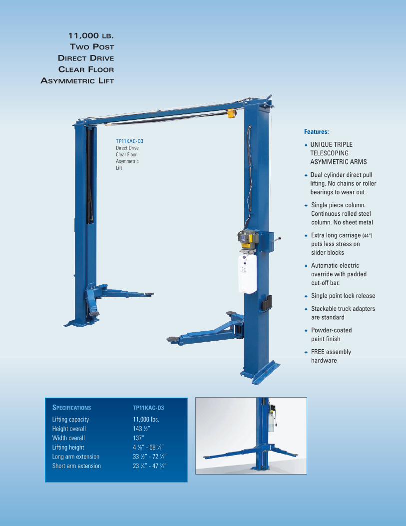
11,000 LB.
TWO POST
DIRECT DRIVE
CLEAR FLOOR
ASYMMETRIC LIFT
Features:
✦ UNIQUE TRIPLE TELESCOPING ASYMMETRIC ARMS
✦ Dual cylinder direct pull lifting. No chains or roller bearings to wear out
✦ Single piece column. Continuous rolled steel column. No sheet metal
✦ Extra long carriage (44”)
puts less stress on slider blocks
✦ Automatic electric override with padded cut-off bar.
✦ Single point lock release
✦ Stackable truck adaptersare standard
✦ Powder-coated paint finish
✦ FREE assembly hardware
TP11KAC-D3Direct DriveClear Floor AsymmetricLift
SPECIFICATIONS TP11KAC-D3
Lifting capacity 11,000 lbs.Height overall 143 1⁄2”Width overall 137”Lifting height 4 3⁄8” - 68 1⁄2”Long arm extension 33 1⁄2” - 72 1⁄2”Short arm extension 23 1⁄4” - 47 1⁄2”

1905 N Main St Suite C, Cleburne, TX 76033 Ph 817-558-9337 Fax 817-558-9740
TUXEDO DISTRIBUTORS LIMITED WARRANTY
Structural Warranty: The following parts and structural components carry a five year warranty:
Columns Top Rail Beam Uprights Arms Swivel Pins Legs Carriages Tracks Overhead Beam Cross Rails
Limited One-Year Warranty: Tuxedo Distributors, LLC (“Tuxedo”) offers a limited one-year warranty to the original purchaser of Tuxedo lifts and Wheel Service in the United States and Canada. Tuxedo will replace, without charge, any part found defective in materials or workmanship under normal use, for a period of one year after purchase. The purchaser is responsible for all shipping charges. This warranty does not apply to equipment that has been improperly installed or altered or that has not been operated or maintained according to specifications.
Other Limitations: This warranty does not cover:
1. Parts needed for normal maintenance2. Wear parts, including but not limited to cables, slider blocks, chains, rubber pads and pulleys3. Replacement of lift and tire changer cylinders after the first 30 days. A seal kit and installation
instructions will be sent for repairs thereafter.4. On-site labor
Upon receipt, the customer must visually inspect the equipment for any potential freight damage before signing clear on the shipping receipt. Freight damage is not considered a warranty issue and therefore must be noted for any potential recovery with the shipping company.
The customer is required to notify Tuxedo of any missing parts within 72 hours. Timely notification must be received to be covered under warranty.
Tuxedo will replace any defective part under warranty at no charge as soon as such parts become available from the manufacturer. No guarantee is given as to the immediate availability of replacement parts.
Tuxedo reserves the right to make improvements and/or design changes to its lifts without any obligation to previously sold, assembled or fabricated equipment.
There is no other express warranty on the Tuxedo lifts and this warranty is exclusive of and in lieu of all other warranties, expressed or implied, including all warranties of merchantability and fitness for a particular purpose.
To the fullest extent allowed by law, Tuxedo shall not be liable for loss of use, cost of cover, lost profits, inconvenience, lost time, commercial loss or other incidental or consequential damages.
This Limited Warranty is granted to the original purchaser only and is not transferable or assignable.
Some states do not allow exclusion or limitation of consequential damages or how long an implied warranty lasts, so the above limitations and exclusions may not apply. This warranty gives you specific legal rights and you may have other rights, which may vary from state to state.
CONTENTS
1. Safety Information 1.1 Note, Caution and Warning 1.2 Important Information 1.3 Safety Instructions
2. Technical Manual
2.1 Product Description 2.2 Technical Data 2.3 Hydraulic Scheme
3. Operation Manual
3.1 Caution and Warning Label 3.2 Operation Instructions 3.3 Emergency Operation Instruction 3.4 Maintenance Instructions 4. Parts List
5. Troubleshooting Guide
-3 - V1.0
1. Safety Information
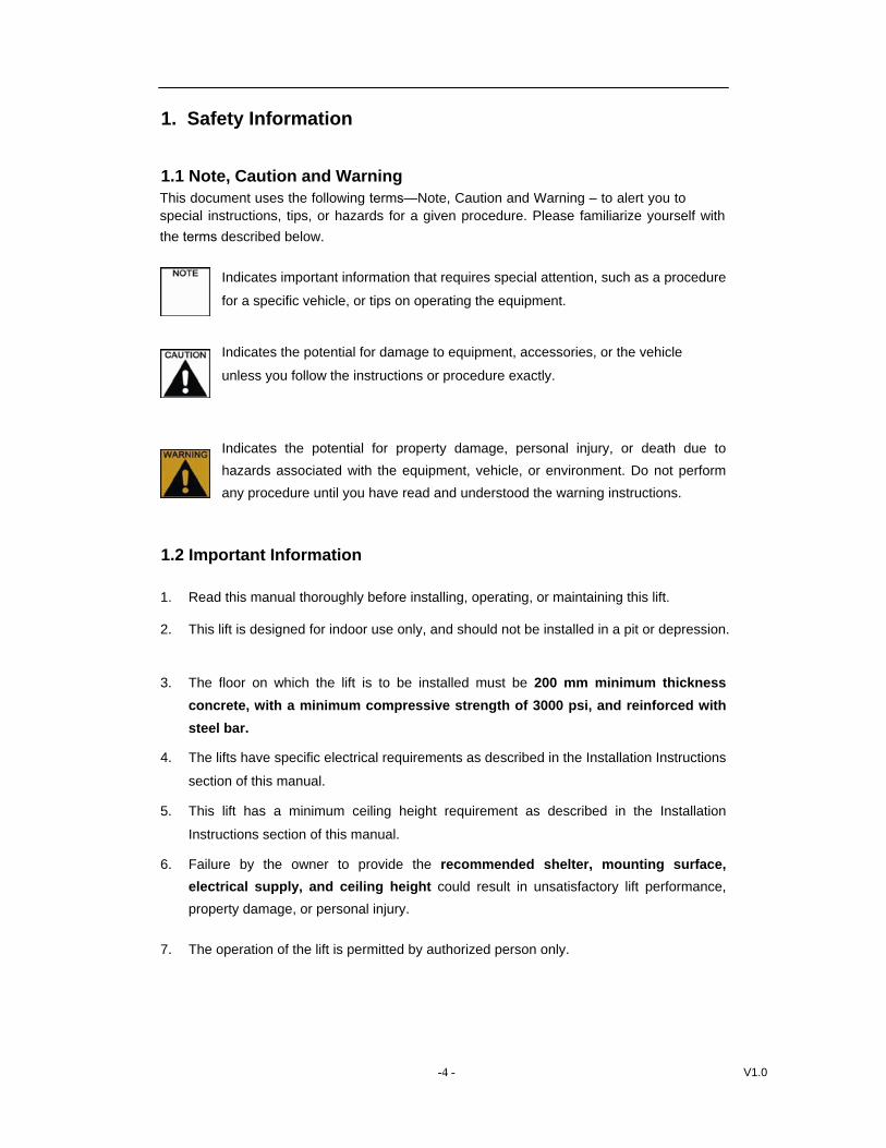
1.1 Note, Caution and Warning This document uses the following terms—Note, Caution and Warning – to alert you to special instructions, tips, or hazards for a given procedure. Please familiarize yourself with the terms described below.
Indicates important information that requires special attention, such as a procedure
for a specific vehicle, or tips on operating the equipment.
Indicates the potential for damage to equipment, accessories, or the vehicle
unless you follow the instructions or procedure exactly.
Indicates the potential for property damage, personal injury, or death due to hazards associated with the equipment, vehicle, or environment. Do not perform any procedure until you have read and understood the warning instructions.
1.2 Important Information
1. Read this manual thoroughly before installing, operating, or maintaining this lift.
2. This lift is designed for indoor use only, and should not be installed in a pit or depression.
3. The floor on which the lift is to be installed must be 200 mm minimum thicknessconcrete, with a minimum compressive strength of 3000 psi, and reinforced withsteel bar.
4. The lifts have specific electrical requirements as described in the Installation Instructions
section of this manual.
5. This lift has a minimum ceiling height requirement as described in the Installation
Instructions section of this manual.
6. Failure by the owner to provide the recommended shelter, mounting surface,electrical supply, and ceiling height could result in unsatisfactory lift performance,property damage, or personal injury.
7. The operation of the lift is permitted by authorized person only.
-4 - V1.0
1.3 Safety Instructions 1. Do not raise a vehicle on the lift until the installation is completed as described in this
manual.
2. Technicians should be trained to use and care for the lift by familiarizing themselves with the
publications listed above. The lift should never be operated by an untrained person.
3. Always position the arms and adapters properly out of the way before pulling the vehicle
into, or out of the bay. Failure to do so could damage the vehicle and/or the lift.
4. Do not overload the lift. The capacity of the lift is shown on cover of this document and
on the lift’s serial number tag
5. Positioning the vehicle is very important. Only trained technicians should position thevehicle on the lift. Never allow anyone to stand in the path of the vehicle as it isbeing positioned and never raise vehicle with passengers inside.
6. Position the arms to the vehicle manufacturer’s recommended pickup points. Raise thelift until contact is made with the vehicle. Make sure that the arms have properlyengaged the vehicle before raising the lift to a working height.
7. Keep everyone clear of the lift when the lift is moving, the locking mechanism is
disengaged, or the vehicle is in danger of falling.
8. Unauthorized personnel should never be in the shop area when the lift is in use.
9. Inspect the lift daily. The lift should never be operated if it has damagedcomponents, or is malfunctioning. Only qualified technicians should service the lift.Replace damaged components with manufacturer’s parts, or equivalent.
10. Keep the area around the lift clear of obstacles.
11. Never override the self-returning lift controls.
12. Use safety stands when removing or installing heavy vehicle components.
13. Avoid excessive rocking of the vehicle when it is on the lift.
14. To reduce the risk of personal injury, keep hair, loose clothing, fingers, and all body parts
away from moving parts.
15. To reduce the risk of electric shock, do not use the lift when wet, do not expose the lift
to rain.
16. To reduce the risk of fire, do not operate equipment in the vicinity of open containers of
flammable liquids (gasoline).
17. Use the lift only as described in this manual, use only manufacturer’s recommended
attachments.
18. Unusual vehicles, such as limousines, RV’s, and long wheelbase vehicles, maynot be suitable for lifting on this equipment. If necessary, consult with themanufacturer or the manufacturer’s representative.
-5 - V1.0
19. The troubleshooting and maintenance procedures described in this manual can be doneby the lift’s owner/employer. Any other procedure should only be performed by trained liftservice personnel. These restricted procedures include, but are not limited to, thefollowing: cylinder replacement, carriage and safety latch replacement, legreplacement, overhead structure replacement.
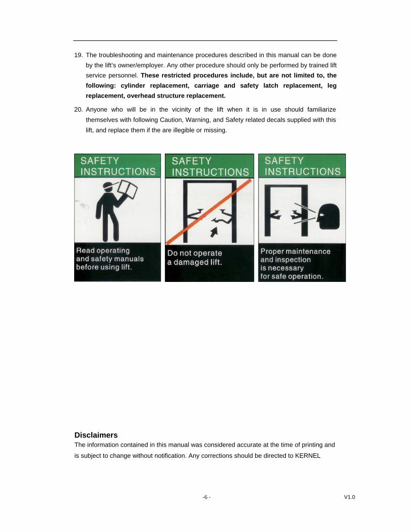
20. Anyone who will be in the vicinity of the lift when it is in use should familiarizethemselves with following Caution, Warning, and Safety related decals supplied with thislift, and replace them if the are illegible or missing.
Disclaimers The information contained in this manual was considered accurate at the time of printing and
is subject to change without notification. Any corrections should be directed to KERNEL
-6 - V1.0

2. Technical Manual
2.1Product Description
The TP11KAC-D3 lift is a surface mounted, frame contact lift incorporating the latest safety
technologies. Designed and manufactured for a lifting capacity of 11,000 lb, it is fully capable for
lifting vehicles, vans and trucks and safely holding them in an elevated position.
The TP11KAC-D3 2-post hydraulic lift consists of a fixed structural unit (base and posts), the mobile unit (carriage and arms), the hydraulic power system and safety
devices.
2.2 Technical Data
Capacity Lifting Height Height Overall Width Overall Front Arm Reach, Max. Front Arm Reach, Min. Rear Arm Reach, Max. Rear Arm Reach, Min. Power Unit Ambient Air Temperature
Ambient Air Humidity Altitude Storage Temperature
5 / 8 " - 7/8"
-
1 4 3
135
99-5/8"
4-3/
8"
137-1/8"
4,990 kg (11,000 lb) 1,740 mm (68-1/2”) 3,648 mm (143-5/8”) 3,484 mm (137-1/8”) 850 mm (33-1/2”) 1,840 mm (72-1/2”) 590 mm (23-1/4”) 1,208 mm (47-1/2”) 400V,
50Hz, 16A, 2.2KW
+5℃ ~ +40℃
30% ~ 95% below 1,000 m above sea level
-25℃ ~ +55℃
108 -1/4"95 -1/4"
"/2
1 -
2
7"
/2 -1
33
5 / 8 " -
1/8"1 3 2
- 69
4 7-1
/2"
7 / 8 " 2 -
3-
1/ 1 2
4
"
116 -7/8"
-7 - V1.0
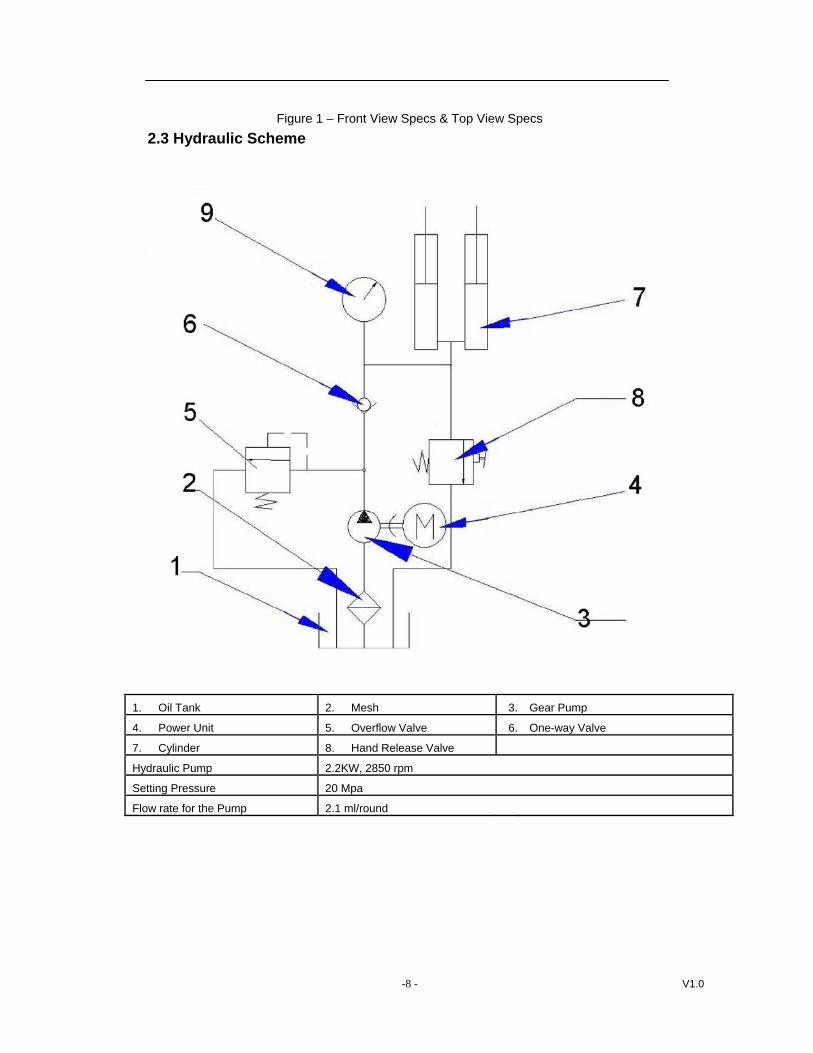
Figure 1 – Front View Specs & Top View Specs 2.3 Hydraulic Scheme
1. Oil Tank 2. Mesh 3. Gear Pump
4. Power Unit 5. Overflow Valve 6. One-way Valve
7. Cylinder 8. Hand Release Valve
Hydraulic Pump 2.2KW, 2850 rpm
Setting Pressure 20 Mpa
Flow rate for the Pump 2.1 ml/round
-8 - V1.0
3. Operation Manual
A
Be sure to read and familiarize yourself with the Safety Instructions at the beginning of manual. Failure to follow Safety Instructions may result in property damage, personal injury B
death.
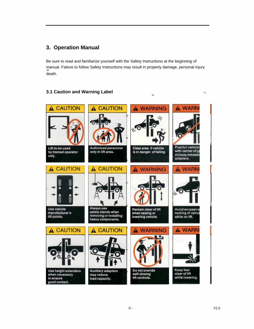
3.1 Caution and Warning Label C
DE
FG
HI
JK
-9 - V1.0
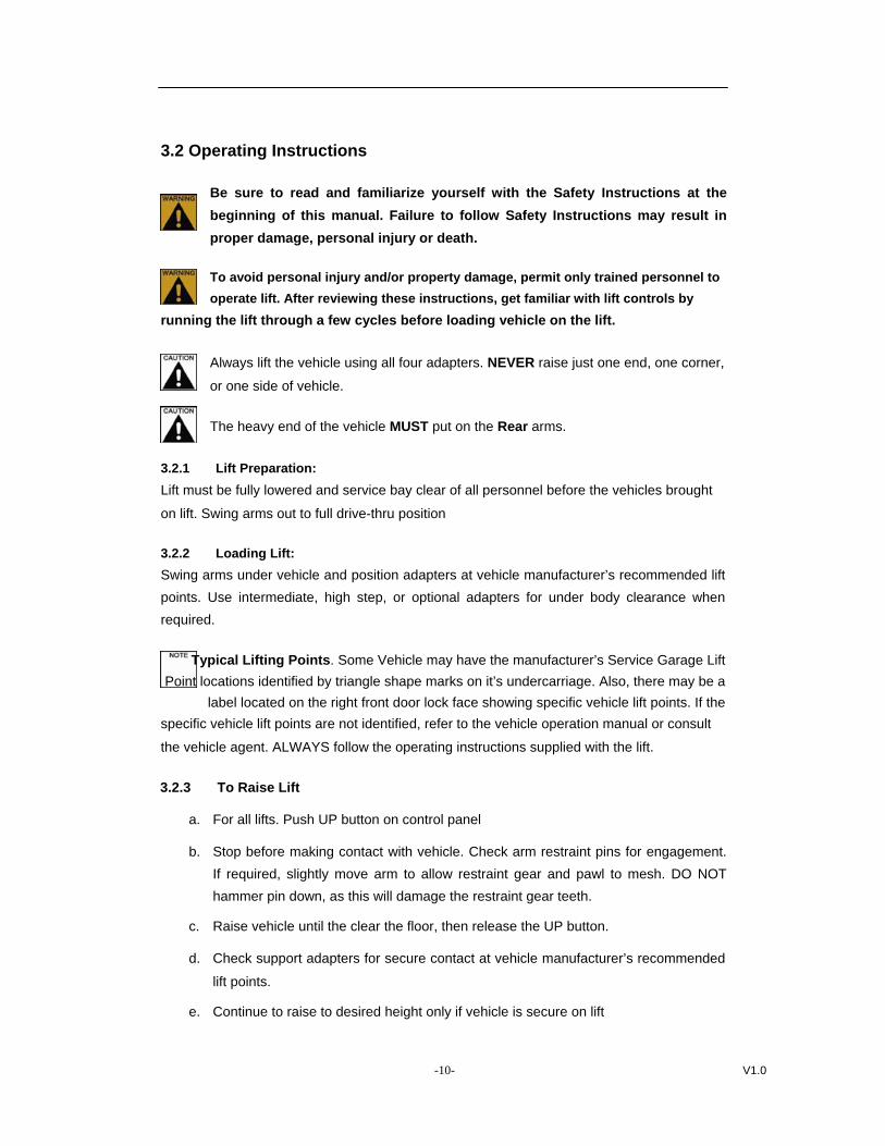
3.2 Operating Instructions
Be sure to read and familiarize yourself with the Safety Instructions at the beginning of this manual. Failure to follow Safety Instructions may result in proper damage, personal injury or death.
To avoid personal injury and/or property damage, permit only trained personnel to operate lift. After reviewing these instructions, get familiar with lift controls by
running the lift through a few cycles before loading vehicle on the lift.
Always lift the vehicle using all four adapters. NEVER raise just one end, one corner,
or one side of vehicle.
The heavy end of the vehicle MUST put on the Rear arms.
3.2.1 Lift Preparation: Lift must be fully lowered and service bay clear of all personnel before the vehicles brought
on lift. Swing arms out to full drive-thru position
3.2.2 Loading Lift: Swing arms under vehicle and position adapters at vehicle manufacturer’s recommended lift points. Use intermediate, high step, or optional adapters for under body clearance when required.
Typical Lifting Points. Some Vehicle may have the manufacturer’s Service Garage Lift Point locations identified by triangle shape marks on it’s undercarriage. Also, there may be a
label located on the right front door lock face showing specific vehicle lift points. If the specific vehicle lift points are not identified, refer to the vehicle operation manual or consult
the vehicle agent. ALWAYS follow the operating instructions supplied with the lift.
3.2.3 To Raise Lift
a. For all lifts. Push UP button on control panel
b. Stop before making contact with vehicle. Check arm restraint pins for engagement.If required, slightly move arm to allow restraint gear and pawl to mesh. DO NOThammer pin down, as this will damage the restraint gear teeth.
c. Raise vehicle until the clear the floor, then release the UP button.
d. Check support adapters for secure contact at vehicle manufacturer’s recommended
lift points.
e. Continue to raise to desired height only if vehicle is secure on lift
-10- V1.0

f. DO NOT go under vehicle if all four adapters are not in secure contact at vehicle
manufacture’s recommended lift point.
g. Repeat complete spotting, loading and raising procedures if required.
h. Push the GROUND button to lower the vehicle to the locking position if locking
latches are not engaged.
DO NOT go under vehicle if locking latches are not engaged.
Before attempting to lift pickup trucks or other truck frame vehicles, be sure that: Vehicle frame is strong enough to support it’s weight and has not
been weakened by modification or corrosion.
Vehicle individual axle weight does not exceed one-half lift capacity.
Adapters are in secure contact with frame at vehicle manufacturers
recommended lift point.
Vehicle is stable on lift
The overhead switch bar will contact the highest point on the vehicle
3.2.5 While Using Lift a. Avoid excessive rocking of vehicle while on lift.
b. Always use safety stands as needed or when removing or installing heavy
components.
c. Always wait until the lift is stable while using the lift.
3.2.5 To Lower Lift a. Remove all tools or other objects from lift area
b. Push DOWN button on control panel
Remain clear of lift when lowering vehicle. Observe pinch point warning decals.
3.2.6 Unloading Lift a. Push GROUND button on control panel, the lift will lower down onto the ground with
beep.
b. Remove adapters from under vehicle and swing arms to full drive-thru position
before moving vehicle
If lift is not operating properly, DO NOT use until adjustment or repairs are made
-11- V1.0
by qualified lift service personnel.
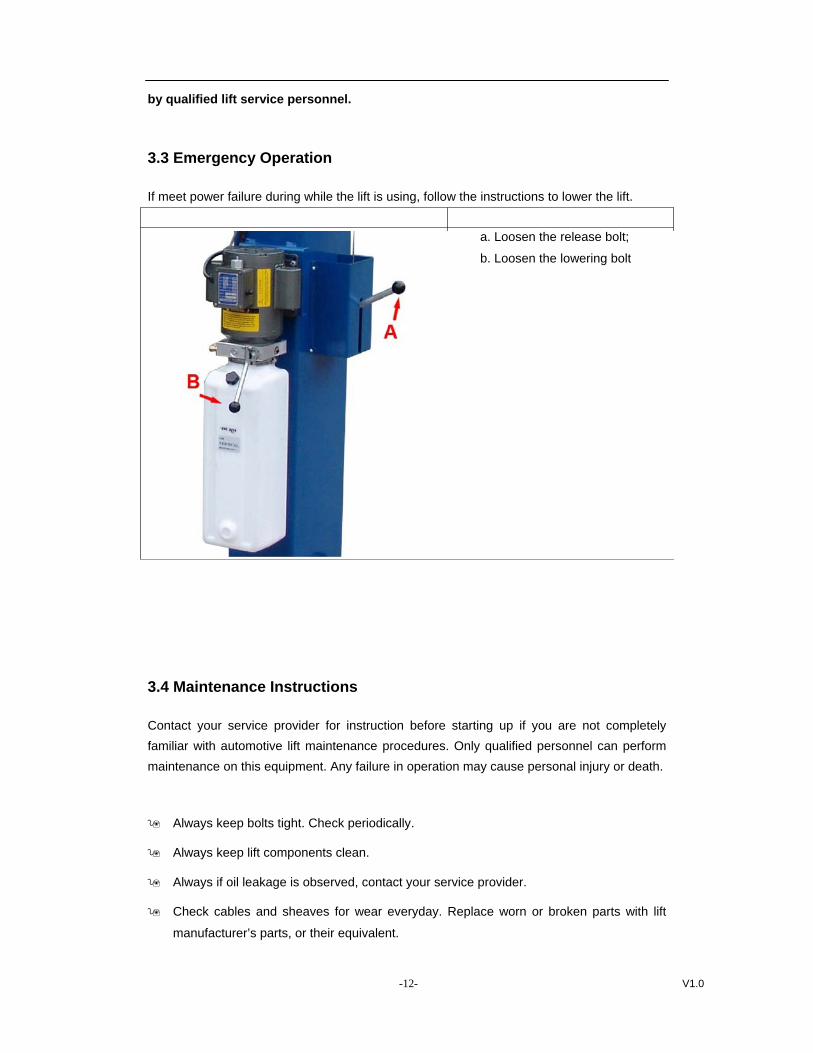
3.3 Emergency Operation
If meet power failure during while the lift is using, follow the instructions to lower the lift.
a. Loosen the release bolt;
b. Loosen the lowering bolt
3.4 Maintenance Instructions
Contact your service provider for instruction before starting up if you are not completely familiar with automotive lift maintenance procedures. Only qualified personnel can perform maintenance on this equipment. Any failure in operation may cause personal injury or death.
Always keep bolts tight. Check periodically.
Always keep lift components clean.
Always if oil leakage is observed, contact your service provider.
Check cables and sheaves for wear everyday. Replace worn or broken parts with lift
manufacturer’s parts, or their equivalent.
-12- V1.0
Every Month
Check equalizer cable tension.
Lubricate locking latch shafts. Push latch handle several times for oil to penetrate joints.
Lubricate the four inside corners of the legs with heavy duty bearing grease.
With lift lowered check the hydraulic fluid level. If necessary add oil as described in the
Installation Instruction section of this manual
Check carriage latch synching: Latches should click at the same time. If necessary adjust
equalization cables as described in the Installation Instruction section of this manual.
Check tightness of all bolts.
Check the nuts for tightness every week for the first month, and every month afterwards.
Every 3 Month
Check anchor bolts for tightness. Anchors should be torque to 122N-m
Check and clean the oil filter
Every 6 Month
Check fluid level of lift power unit and refill if required.
If Lift stops short of full rise or chatters, contact your service provider.
Replace all caution, warning or safety related decals on the lift If unable to read or
missing. Reorder labels from service provider.
-13- V1.0
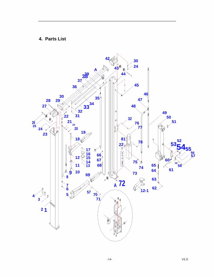
4. Parts List
42 30 24 43 A
39 4437
3845 36
4630 35 47 28 29 34 27 48
32 33
49 3122
50 32
21 51 26 76 2425 77 24 20 19 23
18 81 52 78 22 535455175616 66 5712 15 67 60 14 75 5911 13 68 65 58 74 61 64 10 73 698
963
7 A 7262 6 12-1575 70 4
3 71
2 1
-14- V1.0
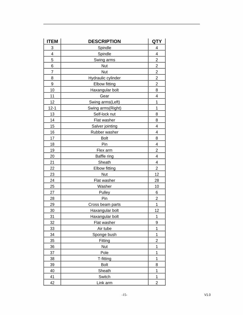
ITEM DESCRIPTION QTY 3 Spindle 4 4 Spindle 4 5 Swing arms 2 6 Nut 2 7 Nut 2 8 Hydraulic cylinder 2 9 Elbow fitting 2 10 Haxangular bolt 8 11 Gear 4 12 Swing arms(Left) 1
12-1 Swing arms(Right) 1 13 Self-lock nut 8 14 Flat washer 8 15 Salver jointing 4 16 Rubber washer 4 17 Bolt 8 18 Pin 4 19 Flex arm 2 20 Baffle ring 4 21 Sheath 4 22 Elbow fitting 2 23 Nut 12 24 Flat washer 28 25 Washer 10 27 Pulley 6 28 Pin 2 29 Cross beam parts 1 30 Haxangular bolt 12 31 Haxangular bolt 1 32 Flat washer 9 33 Air tube 1 34 Sponge bush 1 35 Fitting 2 36 Nut 1 37 Pole 1 38 T-fitting 1 39 Bolt 8 40 Sheath 1 41 Switch 1 42 Link arm 2
-15- V1.0
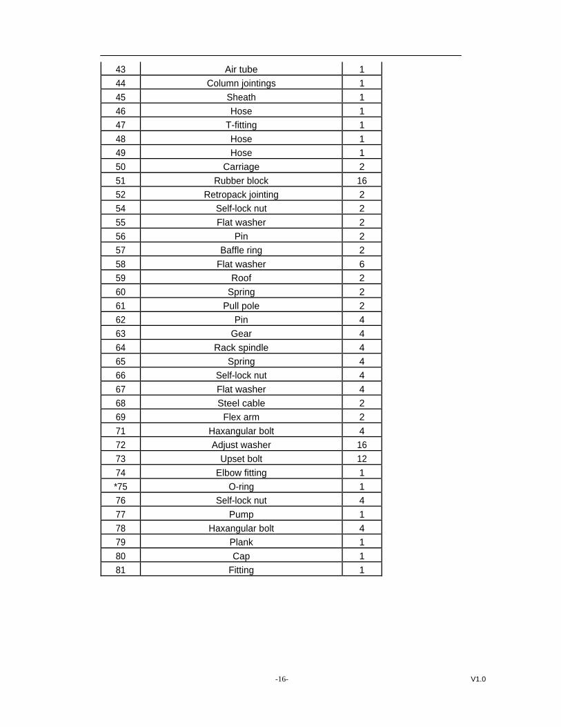
43 Air tube 1 44 Column jointings 1 45 Sheath 1 46 Hose 1 47 T-fitting 1 48 Hose 1 49 Hose 1 50 Carriage 2 51 Rubber block 16 52 Retropack jointing 2 54 Self-lock nut 2 55 Flat washer 2 56 Pin 2 57 Baffle ring 2 58 Flat washer 6 59 Roof 2 60 Spring 2 61 Pull pole 2 62 Pin 4 63 Gear 4 64 Rack spindle 4 65 Spring 4 66 Self-lock nut 4 67 Flat washer 4 68 Steel cable 2 69 Flex arm 2 71 Haxangular bolt 4 72 Adjust washer 16 73 Upset bolt 12 74 Elbow fitting 1 *75 O-ring 1 76 Self-lock nut 4 77 Pump 1 78 Haxangular bolt 4 79 Plank 1 80 Cap 1 81 Fitting 1
-16- V1.0
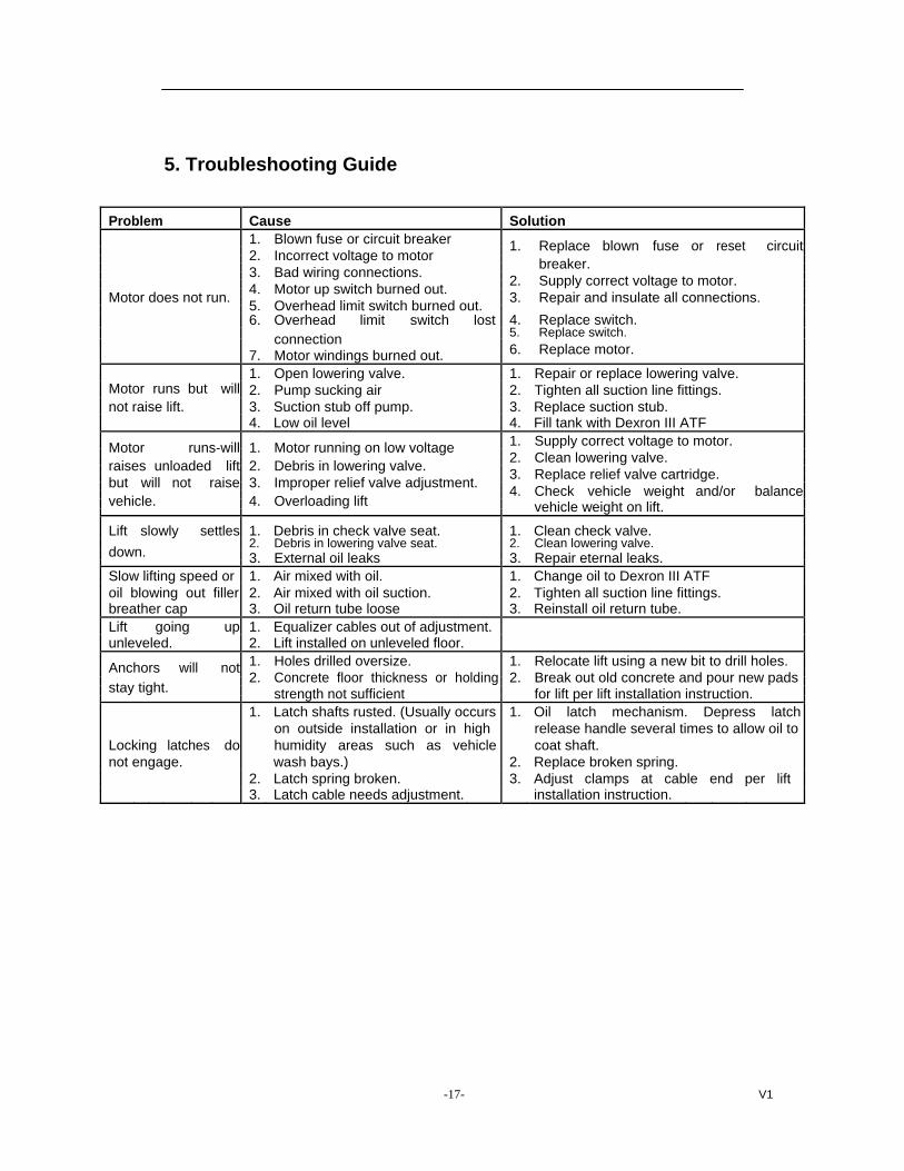
5. Troubleshooting Guide
Problem Cause Solution 1. Blown fuse or circuit breaker 1. Replace blown fuse or reset circuit2. Incorrect voltage to motor breaker.3. Bad wiring connections. 2. Supply correct voltage to motor.4. Motor up switch burned out.Motor does not run. 3. Repair and insulate all connections.5. Overhead limit switch burned out.6. Overhead limit switch lost 4. Replace switch.
5. Replace switch.connection6. Replace motor.7. Motor windings burned out.
1. Open lowering valve. 1. Repair or replace lowering valve.Motor runs but will 2. Pump sucking air 2. Tighten all suction line fittings.not raise lift. 3. Suction stub off pump. 3. Replace suction stub.
4. Low oil level 4. Fill tank with Dexron III ATF 1. Supply correct voltage to motor.Motor runs-will 1. Motor running on low voltage
2. Clean lowering valve.raises unloaded lift 2. Debris in lowering valve. 3. Replace relief valve cartridge.but will not raise 3. Improper relief valve adjustment. 4. Check vehicle weight and/or balancevehicle. 4. Overloading lift vehicle weight on lift.
Lift slowly settles 1. Debris in check valve seat. 1. Clean check valve.2. Debris in lowering valve seat. 2. Clean lowering valve.down. 3. External oil leaks 3. Repair eternal leaks.
Slow lifting speed or 1. Air mixed with oil. 1. Change oil to Dexron III ATFoil blowing out filler 2. Air mixed with oil suction. 2. Tighten all suction line fittings.breather cap 3. Oil return tube loose 3. Reinstall oil return tube.Lift going up 1. Equalizer cables out of adjustment.unleveled. 2. Lift installed on unleveled floor.
1. Holes drilled oversize. 1. Relocate lift using a new bit to drill holes.Anchors will not 2. Concrete floor thickness or holding 2. Break out old concrete and pour new pads
stay tight. strength not sufficient for lift per lift installation instruction.1. Latch shafts rusted. (Usually occurs 1. Oil latch mechanism. Depress latch
on outside installation or in high release handle several times to allow oil toLocking latches do humidity areas such as vehicle coat shaft.not engage. wash bays.) 2. Replace broken spring.
2. Latch spring broken. 3. Adjust clamps at cable end per lift3. Latch cable needs adjustment. installation instruction.
-17- V1

IMPORTANT
POWER UNIT PRIMING PROCEDURE
THE PROBLEM: Power unit runs fine but will not pump any fluid.
Step 1 – Locate the check valve, the flush plug to the left of the lowering valve.
(See drawing below.)
Step 2 – Using an Allen wrench and shop towel – with shop towel in place to catch
fluid – loosen the check valve plug 2 ½ turns to allow it to leak.
Step 3 – Push the START button for one second, then release for three seconds.
Repeat these steps until unit starts pumping fluid.
Step 4 – Tighten the check valve plug.
YOUR POWER UNIT SHOULD BE PRIMED