1100-2184 mvr-sc user manual.rev m jo - bacharach, inc. · 1100-2184 rev 0 5 1 introduction 1.1...
TRANSCRIPT

1100-2184 Rev 0 1

1100-2184 Rev 0 2
WARRANTY POLICY
Bacharach, Inc. warrants to buyer that at the time of delivery this product will be free from defects in material and manufacture and
will conform substantially to Bacharach, Inc.’s applicable specifications. Bacharach’s liability and buyer’s remedy under this warranty
are limited to the repair or replacement, at Bacharach’s option, of this product or parts thereof returned to seller at the factory of
manufacture and shown to Bacharach, Inc.’s reasonable satisfaction to have been defective; provided that written notice of the
defect shall have been given by buyer to Bacharach, Inc. within one (1) year after the date of delivery of this product by Bacharach,
Inc.
Bacharach, Inc. warrants to buyer that it will convey good title to this product. Bacharach’s liability and buyer’s remedy under this
warranty of title are limited to the removal of any title defects or, at the election of Bacharach, to the replacement of this product or
parts thereof that are defective in title.
THE FOREGOING WARRANTIES ARE EXCLUSIVE AND ARE GIVEN AND ACCEPTED IN LIEU OF (I) ANY AND ALL OTHER
WARRANTIES, EXPRESS OR IMPLIED, INCLUDING WITHOUT LIMITATION THE IMPLIED WARRANTIES OF
MERCHANTABILITY AND FITNESS FOR A PARTICULAR PURPOSE: AND (II) ANY OBLIGATION, LIABILITY, RIGHT, CLAIM OR
REMEDY IN CONTRACT OR TORT, WHETHER OR NOT ARISING FROM BACHARACH’S NEGLIGENCE, ACTUAL OR
IMPLIED. The remedies of the buyer shall be limited to those provided herein to the exclusion of any and all other remedies
including, without limitation incidental or consequential damages. No agreement varying or extending the foregoing warranties,
remedies or this limitation will be binding upon Bacharach, Inc. unless in writing,
signed by a duly authorized officer of Bacharach.
Register Your Warranty by Visiting: www.mybacharach.com/warranty-registration/
SERVICE POLICY
Bacharach, Inc. maintains a service facility at the factory. Some Bacharach distributors / agents may also have repair facilities;
however, Bacharach assumes no liability for service performed by anyone other than Bacharach personnel. Repairs are warranted
for 90-days after date of shipment (sensors, pumps, filters and batteries have individual warranties). Should your analyzer require
non-warranty repair, you may contact the distributor from whom it was purchased or you may contact Bacharach directly.
If Bacharach is to do the repair work, send the monitor, prepaid, to the closest service center. Prior to shipping equipment to
Bacharach, visit www.mybacharach.com for a Returned Merchandise Authorization Number (RMA #). All returned goods must be
accompanied by a RMA #. Pack the equipment securely (in its original packing, if possible), as Bacharach cannot be held
responsible for any damage incurred during shipping to our facility. Always include your RMA #, shipping address, telephone
number, contact name, billing information and a description of the defect as you perceive it. You will be contacted with a cost
estimate for expected repairs prior to the performance of any service work. For liability reasons, Bacharach has a policy of
performing all needed repairs to restore the monitor to full operating condition.
NOTICES
Product improvements and enhancements are on-going, therefore the specifications and information contained in this document
may change without notice.
Bacharach, Inc. shall not be liable for errors contained herein or for incidental or consequential damages in connection with the
furnishing, performance, or use of this material.
No part of this document may be photocopied, reproduced, or translated to another language without the prior written consent of
Bacharach, Inc.
Copyright © 2019, Bacharach, Inc., All Rights Reserved.
BACHARACH is a registered trademark of Bacharach, Inc. All other trademarks, trade names, service marks and logos referenced
herein belong to their respective companies.

1100-2184 Rev 0 3
Table of Contents 1 Introduction 5
1.1 About this Manual 5
1.2 Iconography 5
1.3 General Safety Statements 6
2 Product Description 7
2.1 MVR-SC Core Functions 7
2.1.1 Home 7
2.1.2 Navigation Buttons 8
2.1.3 Status Icons 8
2.1.4 Floor List 9
2.1.5 Room/Device list (each floor) 9
2.1.6 Settings 10
2.2 System Components 11
2.2.1 MVR-SC Refrigerant Leak Monitor 11
2.2.2 MVR-300 VRF Refrigerant Leak Detector 11
2.2.3 Ethernet Network Switch 11
2.2.4 Gateway 11
2.2.5 Modbus EZ-Wire Kit 11
2.3 Hardware Overview 12
3 Installation 13
3.1 Network Overview 13
3.2 Floorplan Spreadsheet (CSV) 15
3.3 Gateway IP Address 17
3.4 Hardware Installation 20
3.5 Connecting Relays: Alarm, Fault 21
3.6 Battery for Persistent Memory 21
3.7 Connecting Ethernet Gateways 22
3.8 Connecting MVR-300s 23
3.9 Upload Floorplan Spreadsheet 24

1100-2184 Rev 0 4
3.10 Commissioning 25
3.11 Method 1: Modbus ID Auto-assign 25
3.12 Method 2: Set Modbus ID Manually 29
4 Operation 31
4.1 Overview of Normal Operation 31
4.2 Alarm Detection 31
4.3 Fault Detection 32
4.4 Communication (Comm.) Error 33
4.5 Event History 34
4.6 Service Mode Screen 36
5 Additional Information 37
5.1 Disposing of the Instrument 37
5.2 Service Center Locations 37

1100-2184 Rev 0 5
1 Introduction
1.1 About this Manual
Thank you for investing in a Bacharach MVR-SC Refrigerant Leak Monitor. To ensure operator safety and the proper use of the system, please read the contents of this manual for important information on the operation and maintenance of the instrument.
1.2 Iconography
Alert Icon Description
Danger
An imminently hazardous situation which, if not avoided, will result in death or serious injury.
Warning
A potentially hazardous situation which, if not avoided, could result in death or serious injury.
Warning
Potential electrical shock hazard which, if not avoided, could result in death or serious injury.
Caution
A potentially hazardous situation which, if not avoided, could result in physical injury or damage to the product or environment. It may also be used to alert against unsafe practices.
Important Additional information on how to use the product.

1100-2184 Rev 0 6
1.3 General Safety Statements
DANGER: This product HAS NOT been designed for use in hazardous locations. Failure to comply may result in personal injury or death.
WARNING: NEVER connect the product’s 24V DC inputs directly to AC power supply.
WARNING: DO NOT apply power until all wiring has been completed.
CAUTION: The protection provided by this product may become impaired if it is used in a manner not specified by the manufacturer. Modifications to this instrument, not expressly approved, will void the warranty.
CAUTION: DO NOT continue to use this equipment if there are any symptoms of malfunction or failure. In the case of such occurrence, de-energize the power supply and contact a qualified repair technician or the nearest Bacharach Service Center.
IMPORTANT: Before using this product, carefully read and strictly follow the instructions in the manual. Ensure that all product documentation is retained and available to anyone operating the instrument.
IMPORTANT: The MVR-SC must be installed by a suitably qualified technician who will install this unit in accordance with these instructions and the standards in their industry / country. This document is only intended as a guide, and the manufacturer bears no responsibility for the installation or operation of this unit.
IMPORTANT: Comply with all local and national laws, rules, and regulations associated with this equipment. Operators should be aware of the regulations and standards in their industry / locality for the operation of the MVR-SC.

1100-2184 Rev 0 7
2 Product Description
The MVR-SC Refrigerant Leak Monitor provides centralized monitoring and alarming for multi-
occupant applications utilizing the MVR-300 Refrigerant Leak Detectors. The MVR-SC
continuously monitors all connected devices for alarm and fault conditions and will provide alerts
via the integrated color touchscreen, audible buzzer, and built-in relays.
2.1 MVR-SC Core Functions
Monitor a network of connected MVR-300 refrigerant leak detectors for the following:
• High or low PPM alarm events
• Hardware faults
• Network connectivity
The MVR-SC controller will respond to these events as follows:
• Alarm – activates the alarm relay, flashes the screen to RED, activates the
audible buzzer
• Fault – activates the fault relay, flashes the screen to AMBER, activates the
audible buzzer
• Communication Error – flashes the screen to BLUE, indicates warning on screen
with the specific unit(s)
2.1.1 Home
After inactivity on the touchscreen, the system will always revert to the Home screen. When no alarms or warnings are active, this screen resumes a System Normal state.
Figure 1 - Home Screen

1100-2184 Rev 0 8
2.1.2 Navigation Buttons
Most screens have the following navigation buttons:
2.1.3 Status Icons
Each floor and room will use the following status icons:
Icon Icon Name
Home
Alarm list
Fault list
Comm error
Floor list
Icon Icon Name
Alarm
Fault
Comm error
Normal
Not yet commissioned

1100-2184 Rev 0 9
2.1.4 Floor List
Each floor will designate the highest severity status from all devices on that floor.
2.1.5 Room/Device list (each floor)
Detailed view for each MVR-300 / room in the system grouped on a given floor.
Figure 2 - Floor List
Figure 3 - Room/Device List

1100-2184 Rev 0 10
2.1.6 Settings
Use the settings screen for system configuration changes.
To access the Settings screen, tap the gear icon.
This screen is passcode protected to avoid unintentional changes.
If not already logged in, the Passcode prompt will appear.
Enter the passcode for the MVR-SC controller to unlock and allow changes.
The default system passcode for the MVR-SC is 6388.
Figure 4 - System Settings
Figure 5 - Passcode

1100-2184 Rev 0 11
2.2 System Components
2.2.1 MVR-SC Refrigerant Leak Monitor
The MVR-SC Refrigerant Leak Monitor (MVR-SC) provides centralized alarming and monitoring for all connected MVR-300 Leak Detectors.
2.2.2 MVR-300 VRF Refrigerant Leak Detector
The MVR-300 VRF Refrigerant Leak Detector (MVR-300) provides refrigerant leak detection for occupied rooms in VRF applications.
2.2.3 Ethernet Network Switch
An Ethernet network switch is used to provide connectivity between the MVR-SC Controller and individual gateways.
2.2.4 Gateway
A gateway is used to create small networks of MVR-300 Refrigerant Leak Detectors (up to 15 per gateway) to ease installation and troubleshooting.
2.2.5 Modbus EZ-Wire Kit
Perfectly sized and stripped, pre-bonded wire provides faster, more consistent installation to the MVR-300 Modbus port.

1100-2184 Rev 0 12
2.3 Hardware Overview
MVR-SC Refrigerant Leak Monitor
The MVR-SC provides centralized alarming and monitoring for all connected MVR-300 devices.
Figure 6 - MVR-SC Overview
# Component Description
1 PLC / Touch Screen
2 USB Port
3 Ethernet Port
4 Fault Relay
5 Alarm Relay
6 Modbus Terminal Block
7 Power (24V DC IN)
8 Cable Entries (x4)

1100-2184 Rev 0 13
3 Installation
3.1 Network Overview
IMPORTANT: Prior to installation, download the MVR-SC floorplan spreadsheet
available from MyBacharach.com or on the USB stick supplied with the
controller. This spreadsheet has editable fields for Floor / Room and non-editable
fields for Modbus ID and Gateway IP address. The floor and room fields are to be
completed prior to installation in order to ensure correct wiring and function.
Up to 100 MVR-300 devices can be connected to the MVR-SC. These are to be grouped as Modbus RTU daisy-chain segments of up to 15 devices, terminating at a Gateway. Up to seven gateways can be used in a fully populated network.
Gateways connect via an Ethernet TCP network, through an Ethernet switch, to the MVR-SC. The MVR-SC provides centralized monitoring of all devices in the network, with a 15-second scan rate.
When creating the floorplan, follow these conditions:
• Keep daisy-chain segments of MVR-300 devices as near as possible to the
gateway to which they connect.
• We recommend keeping this distance under 500 ft., if possible, for Modbus
daisy-chain segments. As wire length increases, noise sources can accumulate,
and a greater degree of attention to shielding and grounding is required.
• It is important that the designations in the floorplan spreadsheet “data.csv”
exactly match the actual installed network. Any changes in the physical wiring
must be reflected in the spreadsheet for the system to function.
The following diagram shows an example network using all seven Gateways.
Figure 7 - Connection Diagram

1100-2184 Rev 0 14
Network Creating Notes:
• To mark devices to be on the same floor, those devices must have the same
floor name (capitalization matters). The MVR-SC will display a new “floor” tile for
each unique name appearing in the floorplan spreadsheet, up to 16 distinct
values.
• The floor and room cells can be named with any combination of up to eight digits
of letters and/or numbers.
• It is possible to hardwire up to 15 devices to the controller’s Modbus RTU port.
To indicate these in the floorplan, fill in the cells at the bottom of the spreadsheet
(rows with IP marked “Direct”).
• Each Gateway’s IP Address must be unique. If only one gateway is used, its IP
address should be 192.168.0.1. The IP address for subsequent gateways would
be 192.168.0.2, 192.168.0.3, etc.
• The 7th gateway, if used, has a limit of 10 devices. All other gateways have a
limit of 15 devices.
Figure 8 –Example of a Small Network

1100-2184 Rev 0 15
3.2 Floorplan Spreadsheet (CSV)
When editing the MVR-SC floorplan spreadsheet (data.csv) on a PC, it contains placeholder entries for all possible devices in the network.
Insert the USB stick into a computer that has Excel software installed.
1. Open the flash drive and click the example CSV file titled “data.csv.”
In this file, there are columns labeled: Index, Floor, Room, Gateway, ModbusID, and
IpAddress. Of those six columns ONLY the entries for Floor, Room, and Gateway
should be modified by the user.
.
Figure 10 - Open the data.csv File
Figure 9 - The MVR-SC Floorplan Spreadsheet

1100-2184 Rev 0 16
2. Add the floors and rooms to match the floorplan that has been designed for this specific
building layout.
3. Save the floorplan spreadsheet as a .csv format and upload it onto the USB stick at the
device root folder. The filename must be named as “data.csv” or the MVR-SC will not be
able to find the file when importing.
4. Upload the spreadsheet into the controller from the USB stick using the steps outlined in
Section 3.9 of this manual.
Special Notes:
• There can be multiple gateways on a given floor. Or a single gateway can bridge
across floors. However, pay attention long wire lengths which can be susceptible
to electrical noise.
• The MVR-SC will display floors listed in the order they are encountered in the
spreadsheet rather than alphabetical or numeric order.
• Every assigned room in the “data.csv” file must have a Modbus ID populated. Do
not change these Modbus ID numbers from the defaults.
• The column titled “Gateway” is optional the value from that column will not be
displayed on the MVR-SC.
• Do not add text into any text boxes to the right of Column F and/or below row
114, or the MVR-SC will not be able to read the file.
Figure 11 - Example Layout
1100-2184 Rev 0 17
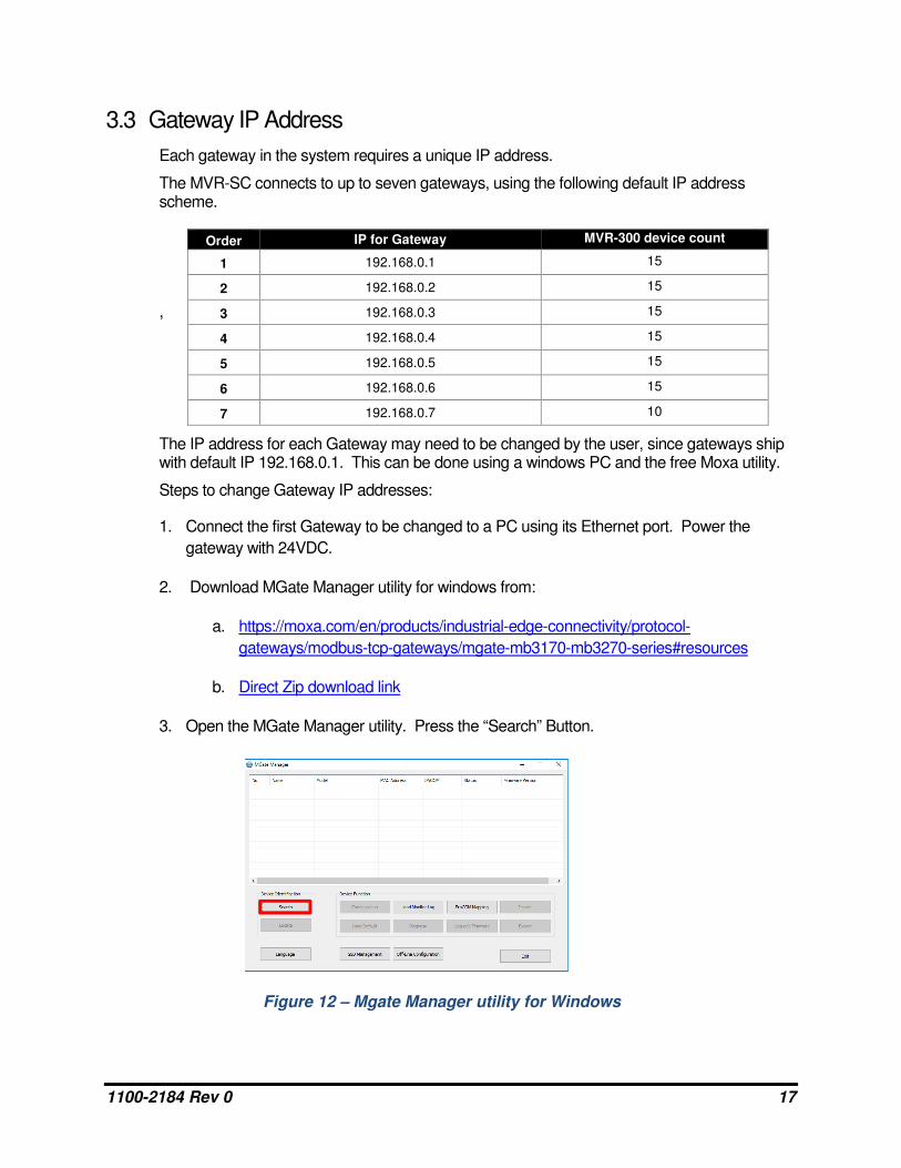
3.3 Gateway IP Address
Each gateway in the system requires a unique IP address.
The MVR-SC connects to up to seven gateways, using the following default IP address scheme.
,
The IP address for each Gateway may need to be changed by the user, since gateways ship with default IP 192.168.0.1. This can be done using a windows PC and the free Moxa utility.
Steps to change Gateway IP addresses:
1. Connect the first Gateway to be changed to a PC using its Ethernet port. Power the
gateway with 24VDC.
2. Download MGate Manager utility for windows from:
a. https://moxa.com/en/products/industrial-edge-connectivity/protocol-
gateways/modbus-tcp-gateways/mgate-mb3170-mb3270-series#resources
b. Direct Zip download link
3. Open the MGate Manager utility. Press the “Search” Button.
Order IP for Gateway MVR-300 device count
1 192.168.0.1 15
2 192.168.0.2 15
3 192.168.0.3 15
4 192.168.0.4 15
5 192.168.0.5 15
6 192.168.0.6 15
7 192.168.0.7 10
Figure 12 – Mgate Manager utility for Windows

1100-2184 Rev 0 18
4. Choose Broadcast Search to search for any connected gateways.
5. When discovered, the Gateway should show up in the table. Select its row and press
Configuration.
a. Note: if this step requires a password it is “moxa”
6. Navigate to the Network tab (the second tab).
Figure 15 - Network tab
7. In the Network tab, the IP can be set to a new value. Change the IP from “192.168.0.1” to
the IP that corresponds with the Gateway index (1 – 7) from the chart above.
Figure 13 – Broadcast Search
Figure 14 – Gateway Configuration

1100-2184 Rev 0 19
8. If this gateway is the first in the network, its IP address is already correct – 192.168.0.1. If
it is the second, change the last digit to be 192.168.0.2, etc.
9. Repeat this process for the remaining gateways in the system.
The gateways contain powerful built-in troubleshooting features. If system troubleshooting is required, please reach out to Bacharach Product Support for relevant documentation and support.
Figure 16 - Network Setting OK screen

1100-2184 Rev 0 20
3.4 Hardware Installation
Mount the MVR-SC in an accessible location for viewing alerts and responding to alarm conditions.
Environment: place the MVR-SC in an indoor setting free from the risk of exposure to water, high humidity or any hazardous conditions.
Accessibility: ensure that the MVR-SC’s touch screen is readily accessible for viewing alerts and responding to alarm conditions.
Connect the controller to a 24VDC supply capable of at least 1 Amp output.
WARNING: Do not apply power until all wiring is in place.
Near to the 24V DC is a terminal block for direct Modbus RTU connections.
This is to be used for troubleshooting or very small direct-connected networks with less than 15 units. A typical large floorplan should be divided into segments connecting via Gateways, as described earlier.
Figure 17 - Modbus Wiring

1100-2184 Rev 0 21
3.5 Connecting Relays: Alarm, Fault
If used, connect the relay output(s) to equipment that will be triggered by each relay.
Note: Take care to ensure proper wiring for intended function: normally open and / or normally closed.
3.6 Battery for Persistent Memory
When 24V DC power is lost to the MVR-SC, a backup battery is used to save the current
state of the system, including the event history and the date and time settings.
This MUST be activated by pulling out the plastic spacer separating the battery from its
contacts. This plastic spacer is labelled with “Pull out to activate battery”.
If this step was skipped, and a system state loss occurs after fully commissioning, re-upload the floorplan from the USB and select Commission All from the settings menu to reconnect all devices.
Figure 18 - Wiring Relays

1100-2184 Rev 0 22
3.7 Connecting Ethernet Gateways
Connect the Ethernet output from the controller to the gateway(s).
Note: If multiple gateways are in use, their Ethernet ports may be daisy chained or an optional Ethernet switch can be used to connect all gateways and the controller onto the same local subnetwork.
Connect the Modbus cable to the gateway output as depicted below.
Each gateway can support a maximum of 15 MVR-300 devices connected in a daisy
chain fashion using the Modbus network cable.
Leave no more than 12 inches (30 cm) for the wire tie-off to each MVR-300.
The shield cable may be left floating or tied to electrical GND at the controller only.
Figure 19 - Wiring Gateways

1100-2184 Rev 0 23
3.8 Connecting MVR-300s
Connect the first MVR-300 device’s Modbus port (3-wire) to the gateway. The unique location on the network for each device will be a combination of its Modbus ID (number 2 through 16), and the unique IP address of the gateway to which they are connected.
Additional resources for the MVR-300 are available online. To download these resources, visit myBacharach.com or use the direct link: http://bit.ly/2wr9eMn.
Wiring Notes:
• The gateway provides the link between the MVR-SC and small groups of MVR-
300 devices, up to 15 per gateway.
• Cable type recommended: Belden 3106, 1.5 twisted-pair/shielded.
• Daisy-chain only, minimizing the total Modbus run length for best performance.
• The best practice is to leave no more than 12-inches (30.5 cm) for the wire tie-off
to each device in order to keep the Modbus wiring as close to a true daisy-chain
as possible.
Figure 20 - Wiring the MVR-300
Tip: An EZ-wire connection is available, and perfectly matched to the Modbus wiring terminal on the MVR-300, which can ensure faster, more consistent wiring.

1100-2184 Rev 0 24
3.9 Upload Floorplan Spreadsheet
1. Power up the MVR-SC. When the System Startup (Home) screen appears, access
System Settings (gear icon).
2. After the System Setting screen appears, insert the USB stick containing the floorplan
spreadsheet into the USB slot of the controller.
Note: Instructions on filling out this spreadsheet are described earlier in this manual in
Sections 3.1 and 3.2.
3. Press Network Config, and then press “Upload CSV” to upload the floorplan
spreadsheet data.csv from the root folder of the USB stick.
A success message will indicate that the upload is complete.
Figure 21 - System Status screen
Figure 22 - System Settings screen

1100-2184 Rev 0 25
3.10 Commissioning
Each MVR-300 ships with default Modbus ID set to 1. These can be set in either of two methods:
1. Modbus ID Auto-assign:
Automatically connect and set IDs using the integrated Magnetic Switch to pair each MVR-
300 to its install location.
2. Set Modbus ID Manually:
Use the RS485 port on the controller to manually set the Modbus IDs, and then install
according to the floorplan, while keeping track of assigned Modbus IDs.
3.11 Method 1: Modbus ID Auto-assign
1. MVR-300 devices can be auto-assigned their Modbus ID using a 2-person verification
technique.
This process gives the added advantage of physically verifying that each connected
device is correctly installed in the assigned room location.
2. Open the Settings Screen (gear icon) and then enter the passcode. (If the passcode has
not been entered, the Device Modbus Pairing Screen will not be accessible).
3. On the MVR-SC touch screen, tap the pin icon in the bottom right of the screen to
advance to the “Floors” screen and then tap the floor that is to be commissioned.
Figure 23 - Floor List screen

1100-2184 Rev 0 26
4. Tap the tile with the first room that is to be commissioned.
This should open the Device Modbus Pairing Screen.
5. At the physical MVR-300 device, have a co-worker tap the Magnetic Switch A (marked
with a single dot “•”) with the magnetic wand for less than a second, and then pull the
magnetic wand away.
This action will put the MVR-300 into Commissioning Mode” and it should beep when the
wand is being pulled away (releasing Magnetic Switch A).
Note: Optionally, the MVR-300 may be taken out of this mode by doing the same tap and
pull-away action on the lower Magnetic Switch B location (marked with a double dot ”••”).
Figure 24 – Tap the tile of room to commission
Figure 25 – The MVR-300

1100-2184 Rev 0 27
6. Back at the MVR-SC touchscreen, after the device has been put into the “Commissioning
Mode”, tap Commission Device. When the device has successfully commissioned, a
“Success” message will appear. If the commission was unsuccessful, an “Unable to
Contact Device” message should appear and the network wiring should be checked.
7. After the commission is successful, tap the “Back” button to go back to the devices screen.
Figure 26 - Device Pairing
Figure 27 - Once commission is successful, tap Back

1100-2184 Rev 0 28
8. On the Devices Screen there should be a green checkmark on the device that was just
commissioned signaling that the commission was successful.
9. Repeat these steps for each room on a floor and each floor in the building until all MVR-
300 devices have been commissioned. When all devices have been commissioned the
green “System Normal” splash will display on the Home Screen.
Figure 28 - Green checkmark appears
Figure 29 - System Normal screen

1100-2184 Rev 0 29
3.12 Method 2: Set Modbus ID Manually
Modbus IDs can be manually assigned to the MVR-300 devices prior to wiring.
Wire a single MVR-300’s Modbus port to the controller’s Modbus terminal block. It is recommended to use the EZ-wire kit available with the MVR-SC controller for ease.
1. From Settings, open the Set Modbus ID screen to select and apply a specific Modbus ID.
2. Tap Search to connect to the device. If the unit does not have factory Modbus ID #1, this
can be restored by doing a factory reset.
In case the MVR-300 has had its Modbus ID changed to some ID other than the default
address 1, do the following to reset to factory settings:
a. Power OFF the MVR-300. Set dipswitch-8 to the ON position.
b. Power ON the MVR-300 (buzzer should sound). Reset dipswitch-8 to the OFF
position (buzzer should turn off).
Figure 30 - Set Modus ID

1100-2184 Rev 0 30
c. Hold the magnet wand to Magnetic Switch A (marked with a single dot “•” on the
MVR-300) for 60 seconds. The device should beep at the end of 60 seconds to
indicate reset.
d. Remove the magnet wand and cycle power. The MVR-300 will have reverted to
default settings including default Modbus ID 1.
e. Specify a unique ID for the MVR-300 – this can a number 2 through 16, inclusive.
f. Tap Set Unit ID to apply this ID.
g. Repeat the above steps for each device. Keep track of the assigned IDs and
install according to the floorplan spreadsheet.
Figure 31 - Set Unit ID

1100-2184 Rev 0 31
4 Operation
4.1 Overview of Normal Operation
The MVR-SC provides centralized monitoring of all segments in the network with a 15-second scan rate.
4.2 Alarm Detection
The MVR-SC controller will provide instantaneous details for any MVR-300 in the network experiencing an alarm condition.
To respond to an alarm event:
1. Tap Mute to silence the alarm. This will mute the buzzer at the controller for 30-minutes.
2. Tap Details to open the Devices in Alarm screen to view the device(s) impacted.
The Devices in Alarm screen will list a single Device/Room tile for each MVR-300 in
active alarm. Each tile will also indicate the severity status and network details for
the MVR-300.
Figure 32 - Alarm Detected screen
Figure 33 - Devices in Alarm screen

1100-2184 Rev 0 32
4.3 Fault Detection
The MVR-SC controller will provide instantaneous details for any MVR-300 in the network experiencing a hardware fault condition.
To respond to a Fault event:
1. Tap Mute to silence the alert. This will mute the buzzer at the controller for 30-minutes.
2. Tap Details to open the Devices in Fault screen to view the device(s) impacted.
The Devices in Fault screen will list the Floor/Room location, status, and
network details for each MVR-300 found to be in fault.
Figure 34 - Fault Detected screen
Figure 35 - Devices in Fault screen

1100-2184 Rev 0 33
4.4 Communication (Comm.) Error
After several unsuccessful attempts to communicate with a commissioned MVR-300 device, the MVR-SC will change the deivce status to Comm. Error and this condition will be indicated with an alert.
To respond to a Comm. Error event:
1. Tap Details to open the Comm. Error screen to view the device(s) impacted.
The Comm. Error screen will list the Floor/Room location, status, and network
details for each affected MVR-300.
Figure 36 – System Status screen
Figure 37 - Comm. Error screen

1100-2184 Rev 0 34
4.5 Event History
The MVR-SC will save new Alarm or Fault events to the Event History. This can be accessed from the Setting screen. The event history is a rolling list of 100 entries. In addition, entries tagged as neither alarm nor fault are created when a device status clears to normal.
Note: The Fault Code is stored as a decimal value and should be converted back to a hex or binary value for easier interpretation of the specific fault codes.
The Time and Date can be set using the UniApps utility.
1. Press and hold the “B” icon in the upper right corner for 3 seconds.
Figure 38 - Event History screen
Figure 39 - Press and hold the "B" icon

1100-2184 Rev 0 35
2. Tap UniApps from the pop-up menu that appears.
3. Select the System tab, and then Time & Date. Choose the date from the calendar tool on
the left side of the screen and the time from the right side of the screen.
4. To return to the home page, press and hold the upper right corner again for 3 seconds.
From the dropdown menu, choose UserApp.
Figure 40 - Tap UniApps
Figure 41 - Choosing the time and date

1100-2184 Rev 0 36
4.6 Service Mode Screen
This utility will disable the audible buzzer and set the relays to their default (normal) position for 30 minutes in order to facilitate maintenance on the network or MVR-300 devices. To access the Service Mode Screen:
1. Open the Settings screen (gear icon in upper right) and tap the Service Mode button.
2. Tap Apply to begin a 30-minute countdown. A timer appears once activated. Tapping
Apply a second time will restart the countdown again to 30 minutes.
Figure 42 - Service Mode screen

1100-2184 Rev 0 37
5 Additional Information
5.1 Disposing of the Instrument
EU-wide regulations governing the disposal of electrical and electronic appliances which have been defined in the EU Directive 2012/19/EU and in national laws have been effective since August 2012 and apply to this device.
Common household appliances can be disposed of using special collecting and recycling facilities. However, this device has not been registered for household usage. Therefore, it must not be disposed of through these channels. The device can be returned to your national Bacharach Sales Organization for disposal. Please do not hesitate to contact Bacharach if you have any further questions on this issue.
5.2 Service Center Locations
Prior to shipping equipment to Bacharach, visit www.mybacharach.com for a Returned Merchandise Authorization Number (RMA #). All returned goods must be accompanied by an RMA #. Pack the equipment securely (in its original packing, if possible), as Bacharach cannot be held responsible for any damage incurred during shipping to our facility.
Location Contact Information Shipping Address
United States
Phone: +1 724 334 5000 Toll Free: +1 800 736 4666 Fax: +1 724 334 5001 Email: [email protected]
Bacharach, Inc. 621 Hunt Valley Circle New Kensington, PA 15068, USA ATTN: Service Department
Europe
Phone: +353 1 284 6388 Fax: +353 1 284 6389 Email: [email protected]
Bacharach, Inc. D13 Santry Business Park, Swords Road, Santry, Dublin 9, D09 KN72, Ireland ATTN: Service Department
Canada
Phone: +1 905 882 8985 Fax: +1 905 882 8963 Email: [email protected]
Bacharach, Inc. 10 West Pearce Street, Unit 4 Richmond Hill, Ontario L4B 1B6, Canada ATTN: Service Department