11. modulation of pulse trains - philips bound... · philips tech. rev. 36,no. 11/12 modulation 329...
TRANSCRIPT

Philips tech. Rev. 36, No. 11/12 MODULATION 329
11. Modulation of pulse trains
Sinusoidal waves are in a way the natural carriers ofinformation, especially in radio communication, forseveral reasons, two of which will be mentioned here.In the first place the system of sinusoidal carriersallows the spectrum to be divided up into an orderlyarrangement of frequency bands; by using a bandfilter one signal can always be selected from the in-numerable number present in the radio spectrum. Inthe second place, the modulated sinusoidal carriergenerally experiences very little distortion during trans-mission because it occupies only a relatively narrowfrequency band. Broadband signals usually do sufferdistortion, because in both cables and radio transmis-sion Fourier components that differ considerably in fre-quency mayalso show considerable differences inattenuation or transit time.In these respects rectangular pulse trains do not
make suitable 'carriers' since they occupy an infinitelybroad spectrum. For this reason they are not used ascarriers for radio transmission. Where informationmodulating a pulse train is to be transmitted by radio,the pulse modulation is always followed by modulationof a sinusoidal carrier, leaving a free choice of fre-quency band. In cable transmission, again, a sine waveis often used as the pulse-train carrier.Why, then, is pulse modulation used?In telecommunication, and especially in telephony,
there is a growing trend towards the large-scale trans-mission of signals both in time-division multiplex(TDM) and in quantized and codedform. Quantizationand coding allow information to be transmitted vir-tually undistorted over large distances. Time-divisionmultiplex, like frequency-division multiplex, allowsmany information signals to be transmitted simulta-neously over a single path. Pulse trains modulated inamplitude are the foundation of these processes.
'Sampling' is the first operation to which an analoginformation signal is subjected when transmitted in
Fig. 43. PAM with short pulses. Each pulse samples the informa-tion signal p(t); the pulse train S(t) forms a series of samples.
TDM, whether or not quantized and coded. The result-ant pulse train, modulated in amplitude by the signal,forms a series of 'samples' of the signal (fig. 43). Theessential question concerning the number of samplesper second that are necessary if no information is to belost is answered by the Nyquist theorem. The samplingof analog signals, incidentally, is a general process thatis widely applied in signal-handling equipment, forexample in CTDs ('charge-transfer devices').
Quantization and coding are the subjects of part Ill.The other subjects just mentioned are based on pulse-amplitude modulation, and will be dealt with shortly.We shall then look at pulse-jl'equency and pulse-duration modulation with reference to the 'VLP'record. First of all we shall look briefly at a number ofbasic concepts.
Some basic concepts
An unmodulated train of rectangular pulses ischaracterized by the amplitude A, the pulse frequencyfe, the phase cp and the duration 'C of the pulses (fig. 44).Modulation of these quantities gives pulse-amplitude.,,modulation (PAM), pulse-frequency modulation(PFM), pulse-phase or pulse-position modulation(PPM) and pulse-duration modulation (PDM). As inthe case of sine waves, variations in phase are accom-panied by variations in frequency, and vice versa. Hereagain we speak of frequency modulation where thefrequency variations are proportional to the informa-tion signal, and of phase modulation where this is thecase with the phase variations (fig.44c and d).As noted earlier, an unmodulated pulse train
(fig. 44a) occupies an infinitely broad spectrum. ltsFourier expansion is:
2 00 1P(t) = (JA+ - A\'- sin nn{Jcos n(Wet + cp). (18)
n L.J nn=l
Here Wc is equal to 2nfe = 2nlT (T being the pulserepetition period), and {J, the 'pulse duty factor' isequal to 'CIT. The phase cp determines the 'position' ofthe pulses, e.g. with respect to the time t = O. (Forcp = 0, t = 0 at the centre of a pulse.)The character of the spectrum is determined by the
value of {J; for example, if {J= t, all even harmonicsare zero. As an examplefig. 45 gives the spectrum for{J= 0.4. This illustrates the important fact that the

330 F. W. DE VRIJER Philips tech. Rev. 36, No. 11/12
PAM
PDM
-f
Fig.44. a) Train of rectangular pulses. A amplitude, T period,T pulse duration. The ratio TIT = {1 is known as the 'pulse dutyfactor'. The pulse frequency fc is equal to liT. The 'pulse position'0, i.e. the distance from the centre of a pulse to the last precedingmoment n'F, is equal to - "'Iwc, where é is the phase (see eq. 18).In PAM (b), PFM (c), PPM (d) and PDM (e), A, T, 0 and Tarefunctions of time. The identical pulse trains c and d are said tobe PF- or PP-modulated, depending on whether the variationsin fe, and hence in liT or those in '" (and hence those in 6) areproportional to the information signal.
amplitude of the nth Fourier component tends to zerowhen 11 increases without limit. This means that thepulse shape in fig. 44a can be reasonably approximatedin a frequency band of finite width; the broader theband the better the approximation. In particular, therise time rr - the time in which the signal valueincreases from 10% to 90% of the peak pulse am-plitude, and which is zero in the ideal case - is shorter
4 6 8 10o 2-n
Fig. 45. Spectrum of an unmodulated pulse train for which thepulse duty factor is 0.4.
the broader the available band B. The relation between'ir and B is
'if R:l 1/2B, (19)
as demonstrated roughly infig. 46.
\\\\\
,,\\\\ I\ I\ I, I, I<:»
1/B
Fig. 46. The Fourier component with the highest frequency of astep signal determines both the rise time Tf of the signal and thebandwidth B of the spectrum. If we assume that this component(dashed) must fit the step (solid line) as shown here, we see thatTf must be about half the period liB of the component.
T T T
Fig.47. Time-division multiplex (TDM). The successive timeintervals ('frames') of duration Teach contain one pulse of eachsignal Sl, S2, Sa, ....
Pulse-amplitude modulation (PAM)
Time-division multiplex (TDM)
The idea of time-division multiplex (TDM) is thatother signals can be transmitted in the intervals be-tween the sampling pulses of a signal (see fig. 43).The time is thus divided into equal intervals of length T,each ofwhich contains one pulse of each signal (fig. 47).On reception the pulses have to be sorted again, whichrequires synchronization of the receiver with the trans-mitter. As we shall presently see, the number of signalswith a given baseband width b that can be transmittedin this way over a transmission channel ofbandwidth Bis equal to B/2b, that is to say just as large as in FDMwith DSB. (In FDM with SSB the number is twice aslarge.) Depending on the application, however, time-division multiplex with PAM can have a great advan-tage over frequency-division multiplex with DSB or

Philips tech. Rev. 36, No. 11/12 MODULATION 331
SSB. This is because frequency division requires theuse of filters, which often take up a lot of space andneed much attention (alignment, stabilization), whereasthe electronic switches required for time division areusually smaller and simpler. This advantage is partic-ularly apparent in telephone exchanges. For this reasonTDM is used in small telephone systems, with the pulsetrains directly sent out after sampling, i.e. uncoded.The application of TDM to coded signals will be dealtwith in part Ill.The maximum number of signals that can be trans-
mitted is equal to the maximum length of the timeinterval T (fig. 47) divided by the minimum width ofthe pulses. This minimum width is twice the rise timeand is therefore equal to I/B, from (19). To determinethe maximum length ofT, we must look at the spectrumof the modulated wave Set).The modulated pulse train Set) in fig. 43 may be
regarded as the product of pet) and an unmodulatedpulse train pet) (eq. 18):
Set) = p(t)P(t) =
2 co 1= (JAp(t) + -- A \' pet) - sin nn{J cos nWet.
n i.....J n11=1
Each harmonic component is thus modulated in am-plitude by the information signal pet) and so has twosidebands (fig. 48). This means that each harmonicoccupies a total bandwidth of 2b. It is now clear that theinformation signal can be recovered from Set) with theaid of a lowpass or bandpass filter, provided the com-ponents do not overlap. This condition gives the maxi-mum value for T, or the minimum value for the pulsefrequency Je (= I/T), which must be at least 2b. Themaximum number of signals that can be transmitted intime-division multiplex, Tmax/(l/B), is thus indeed(I/2b)/(1/B) = B12b. We should note in passing thatthe first step of the filtering operation by means ofwhich the information signal is reconstructed from thepulse train obtained after reception and sorting simplyconsists in holding the sample value until the next onearrives ('sample and hold', fig. 49).
Fig. 48. Spectrum of amplitude-modulated pulse train, schematic.Each Fourier component of the unmodulated pulse train (see forexample fig. 45) gets two sidebands.
Nyquist' s theorem
It could perhaps appear possible that there might bea clever way of recovering the information signal evenwhen the bands in fig. 48 do overlap. In fact, this cannotbe done, since the requirement 'Ic ~ 2b' is a specialform of Nyquist's theorem, which states that to definea signalof bandwidth b at least 2b independent quan-tities per second are necessary. This can be explainedas follows. Let us consider a signal pet) over the timeinterval from 10 to 10 + tI.We expand this as a Fourierseries with components at the frequencies Ill!, 2/l!, ... ,nlt-; The highest frequency in this series is also thebandwidth: nltl = b. Each component is fixed by twoparameters, e.g. the amplitude of the sine phase andthat of the cosine phase. The total of numbers charac-terizing the function is thus 2n = 2btl, and the totalrequired per second is thus 2b.
If we nevertheless sample at a frequency fc smaller than 2b('sub-Nyquist sampling'), then the components at frequenciesbetween fc - band b from the lower sideband of the funda-mental will also be passed by the lowpass filter and cause inter-ference ('aliasing'). A well known instance of this situation isfound in the occurrence of Moiré patterns in superimposed pat-terns of parallel lines (or adjacent sets of railings), with onlyslightly different numbers (kl and k2) of lines or railings permetre. The lower pattern (k2) is effectively sampled in positioninstead ofin time by the spacings in the upper pattern (k1). If k: ismuch greater than ks, a good picture of the lower pattern is ob-tained. If this is not the case, however, and k2 is on the contraryalmost equal to tcs, then the viewer sees mainly Moiré fringes ata spatial frequency of k1 - k2 per metre. In television picturesMoiré fringes can occur between a pattern of horizontal stripesin the subject and the lines that scan the picture. The line scanhere constitutes sampling in the vertical direction.
In television there is no question of horizontal sampling of avideo signal in the ordinary sense. This is however the case wherethe video signal is to be transmitted in digitally coded form (seepart Ill). To keep the sampling rate Je as low as possible in thiscase, sub-Nyquist sampling is applied where the subjective effectsremain below a limit considered to be permissible. The effects (ina stationary picture) consist of stripes with a periodic spacingthat corresponds to the frequency fs = fc - fo of the inter-ference. Here fo is a desired frequency in' the video signal. Witha suitable choice of Ic, for example (11 + t)fL, where /L is theline frequency and 11 an integer, the subjective effect can be
Fig. 49. To recover the information signal from a pulse train S(t)(see fig. 43) it is common practice to hold each sample value untilthe next sample value arrives ('sample and hold'). Most r.f. com-ponents of S(t) have then been filtered out.
332 F. W. DE VRIJER Philips tech. Rev. 36, No. 11/12
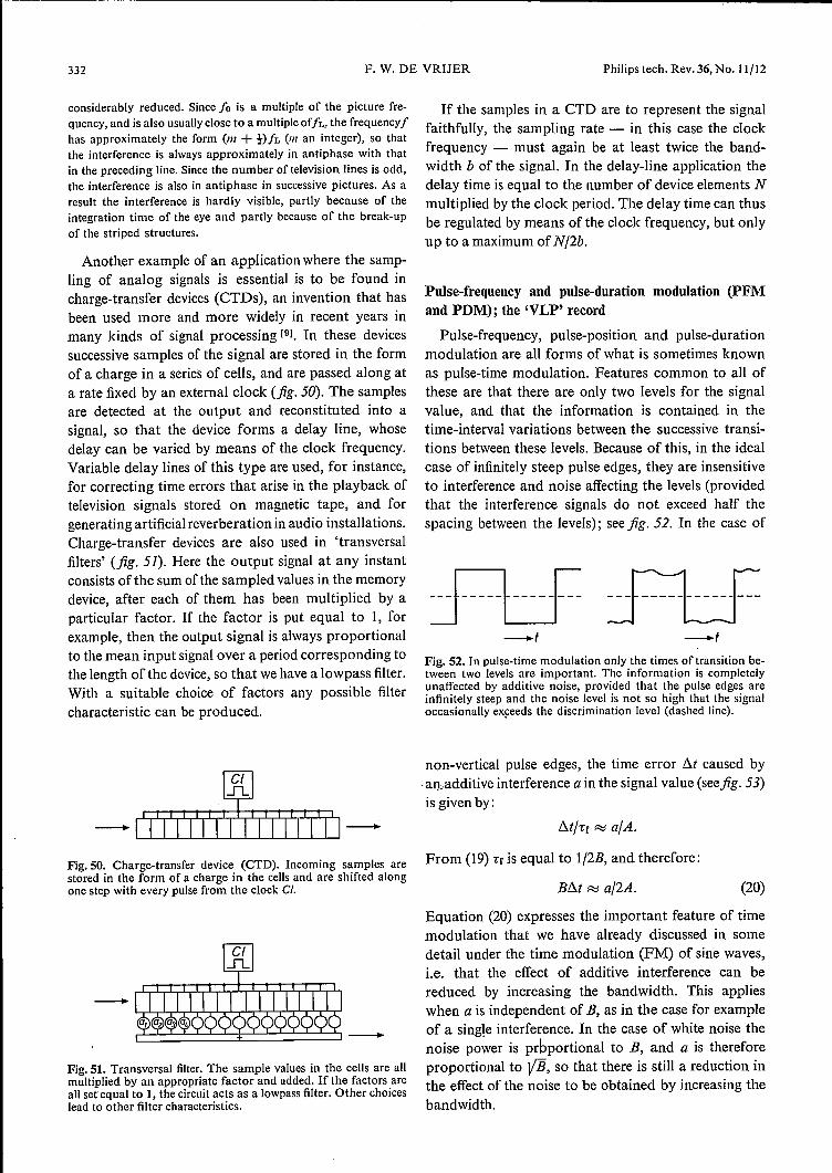
Fig.50. Charge-transfer device (CTD). Incoming samples are From (19) rr is equal to I/2B, and therefore:stored in the form of a charge in the cells and are shifted alongone step with every pulse from the clock Cl. B6.t ~ a/2A. (20)
Equation (20) expresses the important feature of timemodulation that we have already discussed in somedetail under the time modulation (FM) of sine waves,i.e. that the effect of additive interference can bereduced by increasing the bandwidth. This applieswhen a is independent of B, as in the case for exampleof a single interference. In the case of white noise thenoise power is proportional to B, and a is thereforeproportional to VB, so that there is still a reduction inthe effect of the noise to be obtained by increasing thebandwidth.
considerably reduced. Since 10 is a multiple of the picture fre-quency, and is also usually close to a multiple oîfs, the frequency Ihas approximately the form (Ill + !)/L (m an integer), so thatthe interference is always approximately in antiphase with thatin the preceding line. Since the number of television lines is odd,the interference is also in antiphase in successive pictures. As aresult the interference is hardly visible, partly because of theintegration time of the eye and partly because of the break-upof the striped structures.
Another example of an application where the samp-ling of analog signals is essential is to be found incharge-transfer devices (CTDs), an invention that hasbeen used more and more widely in recent years inmany kinds of signal processing [9l. In these devicessuccessive samples of the signal are stored in the formof a charge in a series of cells, and are passed along ata rate fixed by an external clock (jig. 50). The samplesare detected at the output and reconstituted into asignal, so that the device forms a delay line, whosedelay can be varied by means of the clock frequency.Variable delay lines of this type are used, for instance,for correcting time errors that arise in the playback oftelevision signals stored on magnetic tape, and forgenerating artificial reverberation in audio installations.Charge-transfer devices are also used in 'transversalfilters' (fig. 51). Here the output signal at any instantconsists ofthe sum ofthe sampled values in the memorydevice, after each of them has been multiplied by aparticular factor. If the factor is put equal to 1, forexample, then the output signal is always proportionalto the mean input signalover a period corresponding tothe length ofthe device, so that we have a lowpass filter.With a suitable choice of factors any possible filtercharacteristic can be produced.
~
...f1..
I I I I I I !I I I I I-11111111111111-
-Fig. SI. Transversal filter. The sample values in the cells are allmultiplied by an appropriate factor and added. If the factors areall set equal to 1, the circuit acts as a lowpass filter. Other choiceslead to other filter characteristics.
If the samples in a CTD are to represent the signalfaithfully, the sampling rate - in this case the clockfrequency - must again be at least twice the band-width b of the signal. In the delay-line application thedelay time is equal to the number of device elements Nmultiplied by the clock period. The delay time can thusbe regulated by means of the clock frequency, but onlyup to a maximum of N/2b.
Pulse-frequency and pulse-duration modulation (PFMand PDM); the 'VLP' record
Pulse-frequency, pulse-position and pulse-durationmodulation are all forms of what is sometimes knownas pulse-time modulation. Features common to all ofthese are that there are only two levels for the signalvalue, and that the information is contained in thetime-interval variations between the successive transi-tions between these levels. Because of this, in the idealcase of infinitely steep pulse edges, they are insensitiveto interference and noise affecting the levels (providedthat the interference signals do not exceed half thespacing between the levels); seefig. 52. In the case of
-f -fFig. 52. In pulse-time modulation only the times of transition be-tween two levels are important. The information is completelyunaffected by additive noise, provided that the pulse edges areinfinitely steep and the noise level is not so high that the signaloccasionally exceeds the discrimination level (dashed line).
non-vertical pulse edges, the time error 6.t caused by-an.additive interference a in the signal value (seefig. 53)is given by:
6.t/7:f ~ a/A.

Philips tech. Rev. 36, No. 11/12 MODUL~TION 333
The 'VLP' record [lOl is an interesting example of anapplication using a combination of PFM and PDM,and in the rest of this section we shall concentrate onthis application. Played on the appropriate equipment,the 'VLP' record reproduces a television programme ofabout half an hour, complete with colour picture andstereo sound. All the information in the programme iscontained on the record, in a 25-km long spiral trackwith a pitch of 2 (.Lm between circles of diameter 15 and30 cm. The track consists of tiny pits 0.8 (.Lm wide and
a
"Cf
Fig. 53. Pulse edge of finite steepness, without interference (solidline) and with additive interference a (dashed line). The timeerror t1t is alA times the rise time Tr, and therefore the smallerthe steeper the edge.
A
I
Fig. 54. The amplitude of the read-out signal during playback ofa 'VLP' record, as a function of the frequency of the recordedpulse train. At high frequencies the amplitude shows a markeddecrease because the scanning spot is no longer able to discrim-inate between the pits in the disc. Owing to the difference inlinear velocity the critical distance between pits on the track at adiameter of 15 cm corresponds to a lower frequency than on thetrack at a diameter of 30 cm.
0.16 fLmdeep. An optical scanning system and a photo-cell produce trains of electrical pulses from the pits.With a pulse frequency of 6.3 MHz and a disc speed of25 tev]» (1500 rev/ruin) the pit period on the track diam-eter of 30 cm must be about 3.8 fLm(and hence 1.9 fLmon the track diameter of 15 cm). The brightness infor-mation is stored by PFM, i.e. in the variations in thespacings between the centres of the pits. The brightnessat a point of the television picture corresponds to aparticular value of the instantaneous frequency; blackcorresponds to 6 MHz and white to 7 MHz. Theinstantaneous frequency of 5.6 MHz is reserved for theline-synchronization signal ('top sync'). The colour andsound information is stored by PDM, i.e. in variationsin the length of the pits [111.
A two-level system with time modulation is theobvious form of information storage here, because ofthe strongly nonlinear photographic process used fortracing the track and the unavoidable variation in levelduring read-out. The possibility of reducing the effectsof interference by widening the bandwidth is not reallyused. On the contrary, a band of only about 10 MHzis available. This is determined by the size of thelight spot of the scanning system; it is not able todiscriminate between pits that are too short or too closetogether, so that above a particular frequency - whichdepends on the track diameter - the read-out signaldisappears (fig. 54). To accommodate all the informa-tion in the available band the brightness signal is lim-ited in baseband width to 3 MHz. Fig. 55 gives adiagram of the processes applied to the luminance,chrominance and audio signals before they are recordedon the disc. What we are concerned with here is onlythe last step, the PFM and the PDM ofthe track of pits.Pulse-frequency modulation amounts to variation of
the quantity 4> in eq. (18); this will also have the effectof varying the period of the pulses and hence the 'in-stantaneous value' of the pulse frequency (as with sinewaves, variation of the parameter Wc in (18) would bepointless). We thus have frequency modulation of eachFourier component, so that the total spectrum consistsof a superposition of FM spectra in the way illustratedin fig. 27, with the centre frequencies fe, 2fe, 3fe, ....
[9] The 'bucket-brigade delay line' was the first of the storagedevices now grouped under the heading ofCTD. See F. L. J.Sangster, Philips tech. Rev.31, 97 and 266, 1970,and L. J. M.Esser, Electronics Letters 8, 620, 1972.
[10] See the four articles on the video long-play ('VLP') systemin Philips tech. Rev. 33, 178-193, 1973.
[11] These are only numerical examples and are far from defini-tive. It has also been found that it is possible to record the. colour picture signal, including the colour sub carriermodulated by the colour signal, as a single entity in PFMon the disc. (The sound is still applied by POM.)This requiresa larger, bandwidth. It has been decided to do this for theAmerican colour-television signal (NTSC system), but nodecision has been reached on this question in Europe.

334 F. W. DE VRIJER Philips tech. Rev. 36, No. 11/12
The bandwidth B« of the nth spectrum isgiven by therule of thumb (16):
Bn = 2(n6.f +fmax),
wherefmax is the bandwidth ofthe baseband signal andnàf is the frequency deviation of the relevant com-ponent. In the case of the 'VLP' disc, fmax is equal to3 MHz. The value chosen for the frequency deviation!::1f of the fundamental is 0.7 MHz, so that BI is about7.4 MHz and B2 about 8.8 MHz. Overlapping wouldthus occur between the spectrum of the fundamental(6.3 MHz) and that ofthe second harmonic (12.6 MHz)
12.6 18.9MHz-f
o
Fig. 56. Band spectrum of a frequency-modulated pulse train(pulse frequency of unmodulated signal 6.3 MHz, maximum fre-quency of baseband spectrum 3 MHz, frequency deviation of thefundamentalO.7 MHz). Each harmonic produces an FM band.The second harmonic does not appear on the 'VLP' disc, owingto the choice of t for thê pulse duty factor. The bands of thethird and higher harmonics, if still present in the read-out signal,are filtered out.
b..- fr-y U: k._~ lFM
~~o 1..31. 0 5.5/v1Hz
VSB
TV VLP
O_o 3 llLo 0.56 1.68 0 0.25/v1Hz
0.56
Fig. SS. Operations on the luminance signal Y, the chrominance signals R - Y and B - Yand the sound signal S before they are transmitted or recorded on a 'VLP' disc. Chrominanceand sound modulate subcarriers by QAM and FM, respectively. In a television transmissionthese signals, together with the luminance signal, modulate a carrier ofsay 197 MHz in VSB.For recording on the 'VLP' disc the luminance signal is limited in bandwidth, and the chrom-inance and sound carriers are shifted in frequency by mixing. A pilot signal (P) is added forsynchronous detection of the QAM chrominance signal. Finally a pulse train, which has apulse frequency of 6.3 MHz unmodulated, is modulated in frequency by the luminance signaland in pulse duration by chrominance, sound and the pilot signal. The way in which this isdone is explained in fig. 57.
(see fig. 56), if it were not for the fact that the secondharmonic is missing, since the value t has been chosenfor the (mean) duty factor fJ; the spacing between thepits is thus (on average) just as long as the pits them-selves. The spectra of the third and higher harmonicsare completely suppressed. We are only concerned,therefore, with the spectrum of the fundamental. Itshould be noted that, as distinct from the usual situa-
tion in FM radio, the ratio of frequency deviation (6.f)to baseband width (frnax), i.e. the modulation index, isconsiderably smaller than 1, i.e. 0.7/3 or 0.23. Thisagain makes it clear that there is no question of anynoise suppression by band broadening.As stated earlier, the colour and sound information
is stored by PDM, that is by modulation of the quan-tity fJ in (18). As can be seen in eq. (18), and as also

Philips tech. Rev. 36, No. 11/12 MODULATION 335
appears directly from fig. 44e, variation of P impliesvariation of the 'd.c. terms' of the modulated signal.The spectrum of the modulating signal thus enters thespectrum of the modulated signal unchanged. On the'VLP' disc the colour and audio bands, transposed bymixing to relatively low frequencies, fit exactly into thehole left by the clipped brightness band in the spectrum(see fig. 55).Finally, jig. 57 illustrates schematically how the PF-
and PD-modulated signal recorded on the disc is made.
_tFig.57. Method of producing a pulse train of frequency fe that ismodulated in frequency by a signal Yand in pulse duration bya signal B. (In the 'VLP' disc, Ic is equal to 6.3 MHz, Y is theluminance signal and B the combination of modulated chrom-inance subcarrier, modulated sound subcarrier and pilot signal;see fig. 55.) In the figure A stands for a sine wave of frequency Jemodulated in frequency by Y. Addition of A and B and limitingof the sum obtained yields a pulse train that contains the fre-quency variations of A and with pulse durations approximatelyproportional to B. The frequency of B must be appreciably lowerthan the frequency of A, and the amplitude of B must be appreci-ably smaller than the amplitude of A.
Since fJ occurs not only in the d.c. terms but also in all theother components, variation of fJ has other effects as well. Itwillbe shown that in this respect also the value of t is a particularlygood choice for p. For the 'VLP' disc only the constant and thefundamental in (18) are relevant, and we shall confine ourselvesto these. Let us put
p = t + {y + y(t)}/n, (21)
where yIn is a constant deviation of p from the ideal válue t,and yet) is proportional to the modulating signal. We assumethat {y + yet) }/n is much smaller than 1. Substituting (21) in(18) then gives:
pet) = ct + yIn + yln)A + (2/n)A cos(y + y) cos wet """" (t + yIn + yln)A + (2/n)A {I- -!-(y+ y)2} cos wet == (t + yIn + yln)A + (2/n)A(I- -!-y2_ yy- ty2) cos wet.
If y is a sinusoidal signalof frequency fp, we find in the spectrum,in addition to components atfp andlc, interfering components atfe ± fp and fe ± 2fp, deriving from the terms yy cos wet andy2 cos wet respectively. Of these at least the first is missing ify is zero and p thus has on average the ideal value of t; thecomponents at fe ± 2fp are only of the second order in y.It requires considerable mastery of the art of disc-manufacture
to ensure that p remains on average sufficiently close to t. Themost undesirable interfering component is the colour sub carrierat 1.68 MHz (see fig. 55). The first-order interference from thisacts as a sideband at frequency fm ± 1.68 MHz of the FMbrightness signal at the instantaneous frequency fm, and is foundto give a striped pattern with a spatial frequency correspondingto 1.68 MHz. The second-order interference (fm ± 3.36 MHz)falls outside the bandwidth of the PFM signal and is filtered out.The audio and pilot signals are weaker and thereforé less of anuisance.
Finally we should note that, in principle, fJ and rP in (18) areindependent quantities, so that, again in principle, PDM andPFM can be independent of one another and therefore it shouldnot be necessary to separate them in frequency. Frequencyseparation is necessary, however, because the nonlinear signalprocessing and the bandwidth restrietion degrade the isolationand introduce crosstalk.
* **

336 Philips tech. Rev. 36, No. 11/12
A Mariphone transceiver aboard a yacht. The Mariphone service of theNetherlands Post Office allows telephone calls to be made from boats toany subscribers to the public telephone system and is the counterpartof the Mobilophone service available to road users. Sea-going vessels canalso use Mariphone in coastal waters. The system has its own frequencychannels (in the 156-162 MHz band); the modulation is FM.