11 long period fibre gratings
TRANSCRIPT

11
Long Period Fibre Gratings
Alejandro Martinez-Rios, David Monzon-Hernandez, Ismael Torres-Gomez and Guillermo Salceda-Delgado
Centro de Investigaciones en Optica, Leon, Guanajuato Mexico
1. Introduction
In essence, a long period fibre grating (LPFG) is an all-fibre device with wavelength dependent loss. As a band rejection filter, all light in a spectral slice is discarded without affecting the amplitude and phase of neighbouring wavelengths, with the additional advantage of low insertion losses and minimum backreflection (Daxhelet, 2003). LPFGs have been used as band rejection filters, sensors, wavelength selective elements in fibre lasers and amplifiers (Su &Wang, 1999), beam shaping (Mohamed & Gu,2009), etc. In addition, in-series LPFG pairs can be used to form all-fibre Mach-Zender interferometers that are useful as wavelength selective filters for WDM applications; while parallel LPFGs act as wavelength selective couplers or wavelength multiplexers (Chan & Yasumoto, 2007; Shu et. al.,2002). In a common LPFG, the core mode couples to co-propagating cladding modes supported by the cladding-external medium waveguide structure. The specific cladding through which the core mode is coupled is determined by the following resonance condition:
i
eclaeco nn 22
(1)
where econ is the effective index of the fundamental core mode, i
eclan is the effective index
of the ith cladding mode, is the resonance wavelength, i.e. the wavelength where the notch band is formed, and is the period of the grating. As can be clearly seen from this relation the resonance wavelength is determined by the effective refractive indices of the core and cladding modes, so that any geometrical, photo-induced, thermal-induced, or mechanically-induced change (periodic) will modify the position of the resonance wavelength. This property is what makes LPFGs so useful for applications in fields as diverse as optical sensing, biological and chemical sensing, as wavelength dependent loss elements in telecommunication systems and laser and many more. In this chapter we will make a review of the relevant aspects of LPFGs. In section 2.2 we will review the fabrication methods used to write LPFGs in optical fibres; in section 3 we will review the theory behind the operation of LPFGs; in section 4 we will talk about the applications of LPFGs; and, in section 5 we give the conclusions of the present chapter.
2. Fabrication methods of long-period fibre gratings
The inscription of long-period gratings on optical fibre basically consists in the generation of a periodical perturbation of the refractive index in the core, the cladding, or both along the
www.intechopen.com
Fiber Optic Sensors
276
optical fibre (Vengsarkar, 1996). The refractive index perturbation requires a length of 3-5 cm, an amplitude in the range of 10-4 to 10-5 similar to Bragg gratings. In contrast, the
perturbation period in LPFGs is usually larger than 100 m, which is two orders larger than Bragg gratings. In this way, different physical properties of the optical fibre glass or the variation of the optical fibre structure can be used to produce this periodical refractive index perturbation in the fibre, such as; the UV photosensitivity, the residual thermal stress, the photoelasticity and the geometrical modulation of the cladding structure (Hill et. al., 1990; Dianov et. al. 1997; Rao et. al. 2004; Hwang et. al., 1999). In the first case, an ultraviolet light source is used to write the core index modulation in Ge-doped fibres by the photosensitive mechanism, on the other hand, a heating source such as a CO2 laser (Hwang et. al., 1999), or an electric arc system (Bjarklev, 1986), are employed to produce simultaneously the index modulation in the core and the cladding via the residual thermal stress. In a similar way, a mechanical pressure system temporally produces the index modulation in the core and the cladding by the photoelasticity effect (Savin et. al. 2000). Meanwhile, the geometrical modulation of the cladding structure can be done by chemical etching (Vaziri & Chin-Lin, 1997) and other methods. Except the UV photosensitive mechanism, the others one can be used in any type of optical fibre.
In the last 15 years, alternative writing methods of long-period fibre gratings have been
proven after the demonstration of UV radiation method. Some of the most used methods
include; the heating, the mechanical stress and chemical etching between others (Fujimaki
et. al.,2000; Jeong et. al., 2000). The inscription method and the optical fibre type impact in
the physical properties and optical spectral transmission characteristics of the rejection
bands of the LPFGs. Each inscription method produces a particular transversal and
longitudinal refractive index profile. The transversal index profile determines the mode
coupling between the core fundamental mode and the cladding discrete high order modes
involved (Anemogiannis et. al., 2003). Meanwhile, the longitudinal index profile determines
the location and shape of the rejection loss bands (DeLisa et. al., 2000). The combination of
the total index profile and the fibre type define the optical properties of the rejection bands
such as; position of the central resonant wavelength, bandwidth, isolation depth, insertion
loss, induced birefringence, and polarization dependent loss. In the same way, this
combination directly influence in the rejection bands sensitivity to physical variables such
as; temperature, tension, torsion, bending, and external refractive index.
The post-processing of LPFGs is actually used to adjust or stabilize the spectral transmission, as well to improve the sensitivity of the rejection bands in the LPFGs. The sensitivity improve or sensitization of the rejection band to a particular external parameter include, the deposition of some materials over the LPFG (Gu et. al., 2006) and the etching process to reduce the cladding diameter to expose the high cladding modes to the external medium (Chiang et. al., 2001). On other hand, the annealing process is used to tune and stabilize the attenuation bands of the LPFGs (Ng & Chiang, 2002).
2.1 UV long-period fibre gratings
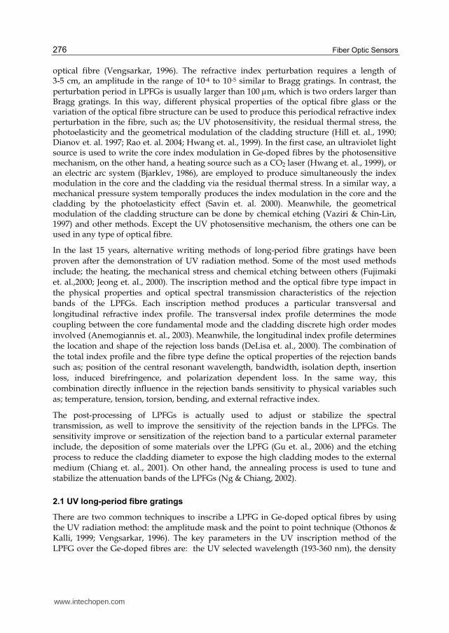
There are two common techniques to inscribe a LPFG in Ge-doped optical fibres by using the UV radiation method: the amplitude mask and the point to point technique (Othonos & Kalli, 1999; Vengsarkar, 1996). The key parameters in the UV inscription method of the LPFG over the Ge-doped fibres are: the UV selected wavelength (193-360 nm), the density
www.intechopen.com

Long Period Fibre Gratings
277
power of the laser, and the exposition time (Othonos & Kalli, 1999). In the first technique, the optical fibre is scanned by the UV beam through an amplitude mask (AM) as is illustrated by Fig. 1(a). The AM contains an array of transparent windows that forms an
illuminated-shadow periodical pattern with a period over the fibre. In case of low UV sensitivity optical fibres, the hydrogenation or the flame brushing process can be used to improve the UV sensitivity in low Ge-doped fibres (Lemaire et. al., 1993; Bilodeau et. al., 1993). Actually, B-Ge codoped optical fibres have been developed to achieve high UV sensitive optical fibre (Williams et. al., 1993). In the point to point technique, the UV beam illuminates a section the optical fibre by a thin slit aperture (S). In this setup, the beam spot
is fixed and the optical fibre moves in the z exes with a period . Both techniques are relative simple to implement; however, the first one is more attractive to mass production, although the point to point technique is more flexible and cheaper than the amplitude mask technique. The main limitation of this technique is that only works in UV photosensitivity fibre.
Fig. 1. LPFG inscription by the UV techniques: a) phase amplitude mask, b) point to point.
The expected z index profile with UV techniques is Gaussian and azimuthally uniform in the transversal plane. In this case, this profile supports the mode coupling between the fundamental mode LP01 in the core and the discrete LP0m in the cladding. The main spectrum transmission characteristics of the rejection bands of UV LPFGs are: wide range wavelength location from visible to infrared, the lowest loss insertion loss < 0.2 dB, the isolation depth is larger than 25 dB and the lowest induced birefringence group. The disadvantages of UV induced LPFGs are temperature limited operation range <250o C and high cost fabrication. The table 1 displays some properties and the sensitivities to some physical parameters. Because the UV LPFG couples modes with azimuthal symmetry the rejection bands are not sensible to twist or bending direction.
2.2 Residual thermal stress long period fibre gratings
The heating and fast cool down of the glass alter the viscosity, it in turns, slightly modified
the refractive index. In this case, the heating process and follow by a fast cool, of the glass
can be use to froze a periodical index modulation across the optical fibre structure (core and
cladding). There are two used methods to generate the periodical index modulation by CO2
radiation (heating absorption) and electrical arc. Both methods can be use in any kind of
fibre. These methods induce a no uniform refractive index profile in the transversal plane,
allowing the coupling to symmetric and asymmetric cladding modes. In the CO2 radiation
www.intechopen.com
Fiber Optic Sensors
278
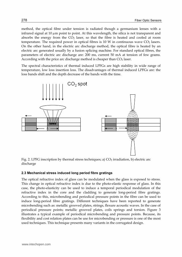
method, the optical fibre under tension is radiated though a germanium lenses with a
infrared signal at 10 m point to point. At this wavelength, the silica is not transparent and
absorbs the energy from the CO2 laser, so that the fibre is heated and cooled at room
temperature. The required power in optical fibres is 10 W in continuous wave CO2 lasers.
On the other hand, in the electric arc discharge method, the optical fibre is heated by an
electric arc generated usually by a fusion splicing machine. For standard optical fibres, the
parameters of electric arc discharge are: 200 ms, current 50 mA at tension of few grams.
According with the price arc discharge method is cheaper than CO2 laser.
The spectral characteristics of thermal induced LPFGs are high stability in wide range of temperature, low loss insertion loss. The disadvantages of thermal induced LPFGs are: the loss bands shift and the depth decrease of the bands with the time.
Fig. 2. LPFG inscription by thermal stress techniques; a) CO2 irradiation, b) electric arc discharge
2.3 Mechanical stress induced long period fibre gratings
The optical refractive index of glass can be modulated when the glass is exposed to stress.
This change in optical refractive index is due to the photo-elastic response of glass. In this
case, the photo-elasticity can be used to induce a temporal periodical modulation of the
refractive index in the core and the cladding to generate long-period fibre gratings.
According to this, microbending and periodical pressure points in the fibre can be used to
induce long-period fibre gratings. Different techniques have been reported to generate
microbending such as: metallic grooved plates, strings, flexure acoustic waves. In the case of
periodical pressure points; metallic grooved plates, coils springs and torsion. Figure 3
illustrates a typical example of periodical microbending and pressure points. Because, its
flexibility and cost relation plates can be use for microbending or pressure is one of the most
used techniques. This technique presents many variants in the corrugated design.
www.intechopen.com

Long Period Fibre Gratings
279
Fig. 3. Stress induced LPFGs, pressure points (a,b) microbending (c,d)
The photoelasticity of the glass allows the inscription of LPFGs practically in any kind of fibre, this include, standard telecommunication fibres, photonic crystal fibres, between others. The amplitude of the refractive index periodical perturbation is the order of 10-4 to 10-5, so the pressure requite is less than 500 gr cm-1, in the microbending case, the amplitude of the perturbation needed is in order of 200- 500 m. The stress induced LPFGs present loss bands with attractive and flexible spectral transmission optical properties. The loss bands are erasable, simple control of the depth (0-20 dB), bandwidth control (10-50 nm) and a large tuning range >250 nm. The drawbacks are high sensitivity to ambient temperature, and insertion loss are in the order of 0.2- 0.3 dB.
2.4 Etching induced long-period fibre gratings
The effective index in the core can be modulated by the geometric modulation of the optical fibre diameter by etching chemical method. The etching induced LPFGs are also known as corrugated LPFGs. This method, consist in locate a photomask over the fibre, and then the optical fibre is immersed in a hydrofluoric acid solution, in this way alternated regions of the fibre are protected of the hydrofluoric solution meanwhile other regions are divested hydrofluoric attack on the silica glass. The diameter in the desvasted regions is controlled by the exposition time, as illustrated in the figure 4. This method is not as popular as UV, thermal or mechanical stress because, their low repeatability and the difficult control of corrugated structured of the fibre. Physically the corrugated LPFGs are fragile to tension or beding stress. The loss bands are high sensitivity to twist because the torsion stress focus in the core diameter.
Fig. 4. Corrugated LPFG
www.intechopen.com

Fiber Optic Sensors
280
Properties UV Residual thermal stress
Mechanical stress
Etching
Length [cm] 2 – 4 2 – 5 3 – 5 2 – 3
Isolation depth [dB] 10 – 30 10 – 25 10 – 20 10 – 15
[nm] > 10 > 10 > 15 > 10
Insertion loss [dB] 0.1 – 0.2 0.1 – 1 0.1 – 0.5 0.1 – 0.3
Modal birefringence 2 (10)-7 1.7(10)-6 7(10)-6 ––
[m] > 100 > 300 > 250 > 500
T [nm /oC] - (0.04– 0.347 ) (0.05 – 0.204) 0.180 – 200 ––
[nm /(rad/cm)] 15 – (6.7 – 25) 6 – 12 -(70 – 100)
[pm/] 0.204 – 1.34 0.1 – 0.4 0.2 – 0.4 1.5 – 2
b [nm/m] 2.5 – 14 -(1.6 – 12) –– -(18 – 25)
ext. index [nm/10-3] -(0.003 – 0.019) -(0.017 – 0.54) 0.22 – 0.5 ––
Range of temperature operation [oC]
< 250 < 1100 < 60 < 1200
Mode order: m = 3rd,4th. Ranges: [=550-650 nm][T:0-200oC], [:0-5 rad/cm], [:0-1000 ], [b:0-5 m-1], [ext. index:1-1.3].
Table 1. Rejection bands properties reported in LPFG with different fabrication methods.
3. Theory of long period gratings
In this section we review the theoretical framework to describe long-period fibre gratings.
We consider the most common case of a step-index fibre with three layers: the central core,
the cladding, and the external medium. We follow the analysis given by Erdogan (Erdogan,
1997) for the calculation of the core and cladding effective refractive indices.
3.1 Characteristic equation for core and cladding modes
The most important parameter for the modelling of long period-fibre gratings are the
effective indices of the core and cladding modes, which determine the coupling wavelength
between co-propagating modes according to the following relation:
( )res efco efclan n (2)
where res is the resonance wavelength, nefco is the effective index of the core mode, assumed
to be single-mode, nefcla is the effective index of a given cladding mode, and L is the period
of the refractive index modulation. Here, for the calculation of the effective index, we
consider that the core mode is not affected by the external medium that surrounds the
cladding, so that the cladding can be considered as an infinitum medium as far as the core
modes concerns. In this particular case, the characteristic equation from which the effective
index of the core fundamental mode can be written as (Erdogan):
1 1
0 0
( 1 ) ( )1
( 1 ) ( )
J V b K V bV b V b
J V b K V b
(3)
www.intechopen.com
Long Period Fibre Gratings
281
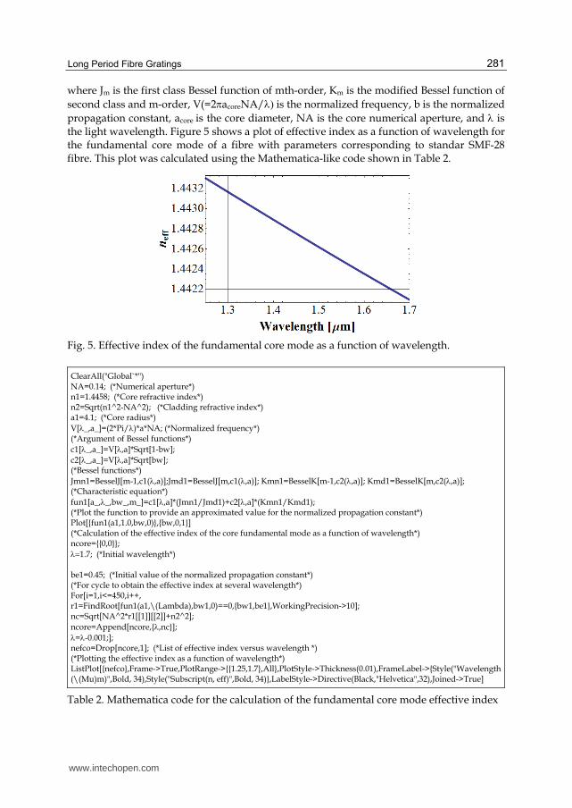
where Jm is the first class Bessel function of mth-order, Km is the modified Bessel function of
second class and m-order, V(=2acoreNA/is the normalized frequency, b is the normalized
propagation constant, acore is the core diameter, NA is the core numerical aperture, and is the light wavelength. Figure 5 shows a plot of effective index as a function of wavelength for the fundamental core mode of a fibre with parameters corresponding to standar SMF-28 fibre. This plot was calculated using the Mathematica-like code shown in Table 2.
Fig. 5. Effective index of the fundamental core mode as a function of wavelength.
ClearAll("Global`*") NA=0.14; (*Numerical aperture*) n1=1.4458; (*Core refractive index*) n2=Sqrt(n1^2-NA^2); (*Cladding refractive index*) a1=4.1; (*Core radius*)
V[_,a_]=(2*Pi/)*a*NA; (*Normalized frequency*) (*Argument of Bessel functions*)
c1[_,a_]=V[,a]*Sqrt[1-bw];
c2[_,a_]=V[,a]*Sqrt[bw]; (*Bessel functions*)
Jmn1=BesselJ[m-1,c1(,a)];Jmd1=BesselJ[m,c1(,a)]; Kmn1=BesselK[m-1,c2(,a)]; Kmd1=BesselK[m,c2(,a)]; (*Characteristic equation*)
fun1[a_,_,bw_,m_]=c1[,a]*(Jmn1/Jmd1)+c2[,a]*(Kmn1/Kmd1); (*Plot the function to provide an approximated value for the normalized propagation constant*) Plot[{fun1(a1,1.0,bw,0)},{bw,0,1}] (*Calculation of the effective index of the core fundamental mode as a function of wavelength*) ncore={{0,0}};
1.7; (*Initial wavelength*) be1=0.45; (*Initial value of the normalized propagation constant*) (*For cycle to obtain the effective index at several wavelength*) For[i=1,i<=450,i++, r1=FindRoot[fun1(a1,\(Lambda),bw1,0)==0,{bw1,be1},WorkingPrecision->10]; nc=Sqrt[NA^2*r1[[1]][[2]]+n2^2];
ncore=Append[ncore,{,nc}];
=-0.001;]; nefco=Drop[ncore,1]; (*List of effective index versus wavelength *) (*Plotting the effective index as a function of wavelength*) ListPlot[{nefco},Frame->True,PlotRange->{{1.25,1.7},All},PlotStyle->Thickness(0.01),FrameLabel->{Style("Wavelength (\(Mu)m)",Bold, 34),Style("Subscript(n, eff)",Bold, 34)},LabelStyle->Directive(Black,"Helvetica",32),Joined->True]
Table 2. Mathematica code for the calculation of the fundamental core mode effective index
www.intechopen.com

Fiber Optic Sensors
282
In the case of the cladding modes the characteristic equation is given as (Erdogan, 1997):
1 2 21 322 2 2 2 22
22 1 2
2 32 3221 212 2 2 22 2 2 2
2 2 1 1 1 2 1 1
232 3 21 32 21
2 2 222 2 12 1
1
1( ) ( ) ( ) ( )
1
( ) ( ) ( )
( ) ( ) (
m m m m
m m m
m m m
u uu J K p a K q a J r a s a
un a a
u uu uu J K p a q a r a
n a n a n a n a
u n u u uu J p a q a r
a a an a
2
2 2 23 1 2 21 32 3 2
2 2 2 2 22 2 2 22 1 1 2 1 1 2
)
( ) ( ) ( ) ( )m m m m
a
n u u n nu J K p a K q a J r a s a
n n a a n n u
(4)
where the parameters in (3) are defined by the following relations {Erdogan, 1997):
1` 2`;efcla efclaim
n im n (5a)
21 322 2 2 22 1 3 2
1 1 1 1;u u
u u w u (5b)
2 2 2 2 2 2
1 1 2 2 3 32 2 2
; ;efcla efcla efclau n n u n n w n n (5c)
1 1 1 1 1 1 1 3 2 1 3 2
1 1 1 3 3 2
( ) ( ) ( ) ( )1 1;
2 ( ) 2 ( )m m m m
m m
J u a J u a K w a K w aJ K
u J u a w K w a (5d)
2 2 1 2 1 2
2 1 2 1 1 2 1 2 1 2 1 1 2 1
2 1 1 2 1 2
1 2 1 2 1 2 1 1 2 1
1 2 1
( ) ( ) ( ) ( ) ( )
1( ) ( ) ( ) ( ) ( ) ( ) ( )
21
( ) ( ) ( ) ( )21
( ) ( ) ( ) ( ) ( )4
( )
m m m m m
m m m m m m m
m m m m
m m m m m
m m
p r J u r Y u a J u a Y u r
q r J u r Y u a Y u a Y u r J u a J u a
r r Y u a Y u r Y u r
s r J u r J u r Y u a Y u a
J u a J
1 2 1 1 2 1 2( ) ( ) ( )m mu a Y u r Y u r
(5e)
where Ym is a Bessel funtion of the the second kind, /0)1/2 is the vacuum impendance,
and m is the azimuthal mode number. Figure 6 shows the calculated effective index
difference between the fundamental core mode and the HE1m (left graph) and HE2m (right
graph) cladding modes assuming a standard single-mode fibre, where we have used Eqs. (3)
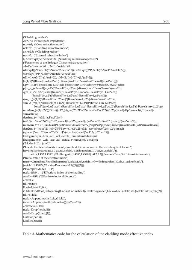
and (4) to find the effective refractive index of the core and cladding, respectively. Table 3
shows the Mathematica-like code used to calculate the effective index of the cladding
modes.
www.intechopen.com
Long Period Fibre Gratings
283
(*Cladding modes*)
Z0=377; (*Free space impedance*)
nco=n1; (*Core refractive index*)
ncl=n2; (*Cladding refractive index*)
acl=62.5; (*Cladding radius*)
next=1; (*External refractive index*)
NAcla=Sqrt(ncl^2-next^2); (*Cladding numerical aperture*)
(*Parameters of the Erdogan Characteristic equation*)
1=I*m*nefcla/Z0; 2=I*m*nefcla*Z0;
u1=Sqrt((2*Pi/ cla)^2*(nco^2-nefcla^2)); u2=Sqrt((2*Pi/cla)^2*(ncl^2-nefcla^2));
w3=Sqrt((2*Pi/cla)^2*(nefcla^2-next^2));
u21=(1/(u2^2))-(1/(u1^2)); u32=(1/(w3^2))+(1/(u2^2));
J=(1/2)*((BesselJ(m-1,u1*aco)+BesselJ(m+1,u1*aco))/(u1*BesselJ(m,u1*aco)));
Kp=(-1/2)*((BesselK(m-1,w3*acl)-BesselK(m+1,w3*acl))/(w3*BesselK(m,w3*acl)));
p(m_,r_)=BesselJ(m,u2*r)*BesselY(m,u2*aco)-BesselJ(m,u2*aco)*BesselY(m,u2*r);
q(m_,r_)=(1/2)*(BesselJ(m,u2*r)*(BesselY(m-1,u2*aco)-BesselY(m+1,u2*aco))
-BesselY(m,u2*r)*(BesselJ(m-1,u2*aco)-BesselJ(m+1,u2*aco)));
r(m_,r_)=(1/2)*(BesselY(m,u2*aco)*(BesselY(m-1,u2*r)-BesselY(m+1,u2*r)));
s(m_,r_)=(1/4)*((BesselJ(m-1,u2*r)-BesselJ(m+1,u2*r))*(BesselY(m-1,u2*aco)-
BesselY(m+1,u2*aco))-(BesselJ(m-1,u2*aco)-BesselJ(m+1,u2*aco))*(BesselY(m-1,u2*r)-BesselY(m+1,u2*r)));
num1(m_)=(1/2)*((J*Kp+((1*\(Sigma)2*u21*u32)/(aco*acl*ncl^2)))*u2*p(m,acl)-Kp*q(m,acl)+J*r(m,acl)-
s(m,acl)/u2);
den1(m_)=-((u32/(acl*ncl^2))*J-
(u21/(aco*nco^2))*Kp)*u2*p(m,acl)+(u32*q(m,acl)/(acl*nco^2))+(u21*r(m,acl)/(aco*nco^2));
num2(m_)= 1*(((u32/acl)*J-(u21*next^2/(aco*ncl^2))*Kp)*u2*p(m,acl)-(u32*q(m,acl)/acl)-(u21*r(m,acl)/aco));
den2(m_)=((next^2/(ncl^2))*J*Kp+(1*2*u21*u32/(aco*acl*nco^2)))*u2*p(m,acl)-
(q(m,acl)*next^2/(nco^2))*Kp+J*r(m,acl)-(s(m,acl)*ncl^2/(u2*nco^2));
Erdoganizq(m_,cla_,aco_,acl_,nefcla_)=num1(m)/den1(m);
Erdogander(m_,cla_,aco_,acl_,nefcla_)=num2(m)/den2(m);
(*Modes HE1n (m=1)*)
(*Locate the desired mode visually and find the initial root at the wavelength of 1.7 um*)
h1=Plot({Erdoganizq(1,1.7,a1,acl,nefcla)/I,Erdogander(1,1.7,a1,acl,nefcla)/I},
{nefcla,1.437,1.43901},PlotRange->{{1.4385,1.43901},{-0.2,0.2}},Frame->True,GridLines->Automatic)
(*Initial value of the effective index*)
nstart=Quiet(FindRoot(Erdoganizq(1,cla,a1,acl,nefcla1)/I==Erdogander(1,(cla,a1,acl,nefcla1)/I,
{nefcla1,1.43895},WorkingPrecision->15)((1))((2)));
(*Example: Mode HE11*)
necla={{0,0}}; (*Effectiuve index of the cladding*)
neff={{0,0}};(*Effectiuve index difference*)
cla=1.7;
n11=nstart;
For(i=1,i<=450,i++,
r11cla=FindRoot(Erdoganizq(1,cla,a1,acl,nefcla1)/I==Erdogander(1,cla,a1,acl,nefcla1)/I,{nefcla1,n11})((1))((2));
n11=r11cla;
necla=Append(necla,{cla,r11cla});
(neff=Append(neff,{cla,nefco((i))((2))-n11});
cla=cla-0.001;);
necla=Drop(necla,{1});
neff=Drop(neff,{1});
ListPlot(necla);
ListPlot(neff);
Table 3. Mathematica code for the calculation of the cladding mode effective index
www.intechopen.com

Fiber Optic Sensors
284
Fig. 6. Effective index difference between the fundamental core mode and HE1m (left graph), and HE2m (right graph) cladding modes.
3.2 Coupled mode equations
In the case of o LPFG, we must consider the coupling between forward propagating modes
obeying the coupled mode equations (Bures,2009), which in the case of one forward
propagating core mode and forward propagating cladding modes can be written as:
( )
( ) ( )com co m
m
dA zi B z C z
dz (6a)
( )( ) ( ) ( )
jco j co m j m
m j
dB ziA z C i B z C z
dz
(6b)
Assuming that the periodic perturbation of the refractive index is much lower that the unperturbed refractive index we can approximate the coupling coefficient by:
*
0
ˆ ˆ( ) ( , ) ( ) ( )2
co mi zco m co m
A
kC n r n r z r r e dA
e e (7a)
where Cm-co=(Cco-m)*, ˆ ( )m re is the normalized electric field, dA is a differential of area, and the integration is over the infinite area.
Here, we consider the uniform refractive index perturbation n(r,z) of a three-layered waveguide written as:
2
1
2
1 2
2
( , )
0
co
cla
i z
co
i z
cla
n e r a
n r z n e a r a
r a
(8)
Then the coupling coefficient can be written as:
www.intechopen.com

Long Period Fibre Gratings
285
0
1 1 2 22
k i z i coC e n n I n n Ico m co m mcla
(9)
where
2
2co mneff
(10)
and
1
2
1
*1
0
*2
ˆ ˆ( ) ( )
ˆ ˆ( ) ( )
a
m co m
a
m co m
a
I r r rdr
I r r rdr
e e
e e
(11)
In writing (9) and (10) we have used 2 ( ) / 2 co mco m eco ecla effn n n , i.e., it is
expressed in terms of the effective refractive index difference between the core and cladding modes. The integrals in (11) can be seen as overlapping factors between the core and cladding modes, which determine the changes in the transmission spectrum when there are changes in fibre dimensions, the external refractive index, temperature and stress, since in all cases the effect is to change the effective refractive index of the core and cladding modes.
In order to find an analytical solution for the amplitudes of the core and cladding modes we
consider only the coupling to one cladding mode, so that, after differentiating Eqs. (6a) and
(6b) and solving the resultant equations we can obtain (Bures, 2009):
2 22 22 2
1 1( ) cos sin2 2
i z i z
co co m co mA z A C z e B C z e
(12a)
2 22 22 2
2 2( ) cos sin2 2
i z i z
m co m co mB z A C z e B C z e
(12b)
Now we consider specific boundary conditions found in LPFGs, where Aco(0)=1 and Bm(z)=0 which results in (Bures, 2009)
22
cos2
2( )2
2sin
22 22 /2
C zco mi z
A z eco
i C zco mCco m
(13a)
www.intechopen.com
Fiber Optic Sensors
286
2
2 222
( ) sin2/ 2
i zco m
m co m
co m
CB z i C z e
C
(13b)
From here we can now write the transmittance at the core as:
22 2/ 22 22 2( ) cos sin222 2/ 2
T z C z C zco co m co mCco m
(14)
This equation is only valid for uniform LPFGs with a step change. For real LPGs, the index change is much more complicated since, for example, in arc induced LPFGs the zone
affected by the electric arc spans >300 m, and is asymmetric in both, the longitudinal and transverse directions. This fact makes the modeling of such gratings a really challenging task. A qualitative analysis of this and other types of gratings can be done only by calculating their effective indices (core and clad) and matching the observed resonance to the calculated dispersion curves of the effective refractive index.4. Applications of long-period fibre gratings in optical sensing
One of the more important applications of LPFGs is as sensing elements. Owing to the well-known advantages over conventional sensors, such as high resolution, low cost, light weight, and multiplexing possibilities, several optical fibre sensors have evolved from laboratory experiments into commercial products. Although many sensor schemes have been proposed, probably the most popular ones are based on evanescent field interactions (Villatoro et. al. , 2005), fibre Bragg gratings (FBGs) (Othonos & Kalli, 1999), and fibre long period gratings (LPGs) (Vengsarkar et. al., 1996; Vengsarkar & Bhatia, 1996). Fibre gratings have attracted considerable attention as ideal detectors since the information of the physical phenomena is encoded in wavelength. Fibre gratings are very sensitive to physical perturbations like temperature, strain, and pressure (Othonos & Kalli, 1999; Vengsarkar & Bhatia, 1996; Kersey et. al., 1997), however, in combination with a suitable transducer can monitor other magnitudes such as humidity (Liu et. al., 2007), or electric fields (Abramov et. al., 1999). The sensitivity of LPGs to ambient refractive index is higher than that observed in fibre Bragg gratings, mainly due to the fact that in the case of cladding modes the guiding structure is formed by the cladding and the external medium in such way that any change in the ambient refractive index modifies the spectral response of the LPGs (Vengsarkar et. al., 1996; Vengsarkar & Bhatia, 1996).
The potential applications of LPG are strongly determined by the sensitivity of these devices to the influence of the surrounding environment. In general, the performance of devices used in communication, it is expected to have low sensitivity to changes of the surrounding media. By contrast, the LPGs fabricated for sensing applications the characteristics of the devices are designed to enhance its intrinsic sensitivity. Thus, a complete analysis of the sensitivity of LPGs to external ambient is necessary prior to practical devices design. The coupling of the fundamental core mode to cladding modes is determined by the period, the effective refractive index of the core and the cladding. These three parameters, and in consequence the LPG resonant wavelength, will be affected by changes in temperature and strain of the fibre. Additionally, since the cladding modes interact with the buffer or any
www.intechopen.com
Long Period Fibre Gratings
287
other material in close contact with the cladding of the fibre, the wavelength response of the LPG is also affected by the changes in the refractive index of the external medium. Shu et al. ( Shu et. al., 2002) have presented a complete investigation of the shift in the center of the wavelength of the resonant peaks of the LPG due to temperature, strain and external refractive index changes, and can be expressed by
res res resres sur
sur
d d dT S n
dT dS dn
(15)
where )/(),(),(surresresres
dndanddSddTd are the temperature, strain and surrounding refractive index sensitivity of the resonant wavelength, respectively. In the following sections a detailed expression for such sensitivities is going to present and discussed.
4.1 Temperature sensing with long-period fibre gratings
For more than three decades investigation over optical fibre thermometers has been
growing. Early fibre-optic temperature sensors were two fibre interferometers in which
temperature was measured by fringe displacements (Hocker, 1979). Later, one-fibre
interferometers were proposed and demonstrated that had practically no cross sensitivity
(Eickhoff, 1981). Recently, a new generation of fibre-optic temperature sensors based on
LPGs has been developed in which temperature is measured in the spectral domain by
resonant wavelength shifts, rather than fringe displacements. The vast majority of fibre
temperature sensors reported so far have been designed to operate in a range from 20 C to
200 C. However, there are a variety of applications in which high-temperature sensing is
important, for example, for monitoring furnace operation or volcanic events, or in fire alarm
systems, etc. (Brambilla et. al., 2002). There exist a variety of materials and techniques to
fabricate optical fibre thermometers for high temperature. Among them, LPG inscribed with
a pulsed CO2 laser (Davis et. al., 1998), or using an electric arc (Kosinski & Vengsarkar, 1998)
have been attracting attention due to their simply fabrication process and their wide range
of measurement. The expression for the temperature sensitivity of a LPG, whether is used to
measure low- or high-temperature, can be expressed as (Shu et. al., 2002),
,
,
effeffco co cl cl mres
res effeffco cl m
n nd
dT n n
(16)
where is the thermal expansion coefficient of the fibre, co and cl are the thermo-optic of
core and cladding materials, respectively and is the waveguide dispersion described as (Shu et. al., 2002):
,
/reseffeff
co cl m
d d
n n
(17)
In general for silica-based fibre the effect of thermal expansion coefficient is lower than of the thermo-optic, represented by the second term in the parenthesis. However, its influence in the analysis of temperature sensitivity cannot be ignored. For standard fibre, the second term in the parenthesis could be higher than zero, whereas for B–Ge co-doped fibre this
www.intechopen.com

Fiber Optic Sensors
288
value is lower than zero, because boron doping can decrease significantly the thermo-optic coefficient of the core (Shu et. al., 2001). Thus, it is to be expected that the thermal responses of LPFGs produced in these two fibre types will exhibit opposite trends. It is also evident from eq. (17) that the temperature sensitivity of a LPG is also dependant on the cladding mode excited and in consequence depends on the technique used to fabricate the LPGs.
4.2 Strain sensing with long-period fibre gratings
Grating-based sensors have redefine the concept of “smart structures” since these devices have been successfully integrated or embedded into the materials to allow monitoring of parameters such as load, strain or vibration from which the health of the structure can be evaluated and tracked in a real-time basis. This success is mainly due to the well-known advantages of the optical fibres for sensing, such as EMI immunity, electric passive operation, low weight, small size, and high sensitivity, but also because these grating-based sensors have the inherent self-referencing capability and are easily multiplexed. The strain response of a long-period fibre grating arise due to the physical elongation of the fibre, changing the grating pitch and the effective refractive index of the core and cladding due to the elastooptic effect. The LPG sensitivity to strain can be expressed as follows (Shu et. al., 2002),
,
,
1
effeffco co cl cl mres
res effeffco cl m
n nd
dS n n
(18)
where co and cl are the elastooptic coefficient of the core and cladding materials, respectively. The strain response of a LPG depends on the cladding mode excited and the elastooptic coefficient of the core and cladding materials. It can be seen form eq. (18) that a LPG is strain-insensitive when the second term in the parenthesis is equal to -1.
4.3 Refractive index sensing with long-period fibre gratings
The refractive index (RI) is a fundamental material property, in a variety of applications, the measurement of the RI is very important since different chemical substances as well as several physical and biological parameters can be detected through measurements of this parameter. In bio-sensing, for example, there is a need to monitor RI changes on the order of 10−4 to 10−7 which may be caused by molecular binding, chemical or biochemical reactions, or by changes suffered by a thin bio-layer measure very small RI changes in small volumes of fluid. Traditional bulk refractometers are not appropriate for such an application; in such cases optical fibre refractometers (OFRs) constitute an alternative. OFRs have some advantages over their bulk counterparts, such as high resolution, low cost, light weight, and multiplexing possibilities. Several OFRs based on side-polished single-mode fibre, core-exposed or tapered multimode fibres, fibre Bragg gratings (FBGs), or long period gratings (LPGs) have been reported so far (Lopez-Higuera & Ed., 2002). In a LPG the guided light interacts with the external medium so there is no need to modify the fibre. The effective index of the excited cladding modes depends on the refractive index of the core, cladding and external medium materials. This dependence is clearly observed in the expression derived for the sensitivity of the LPG to external refractive index (Shu et. al., 2002; Miyagi & Nishida, 1979)
www.intechopen.com
Long Period Fibre Gratings
289
2 3
3/23 2 2
,8
m res extresres
effeffextcl cl co cl extcl m
u nd
dn r n n n n n
(19)
um is the m-th root of the zeroth-order Bessel function of the first kind, rcl and ncl are the radius and refractive index of the fibre cladding, respectively. In this case is more evident that the sensitivity is rather greater for higher order modes and it can be enhanced by reducing the cladding radius (Martínez-Rios, A. et. al. (2010).) since the term in parenthesis is dependent on ( 3
clr ).
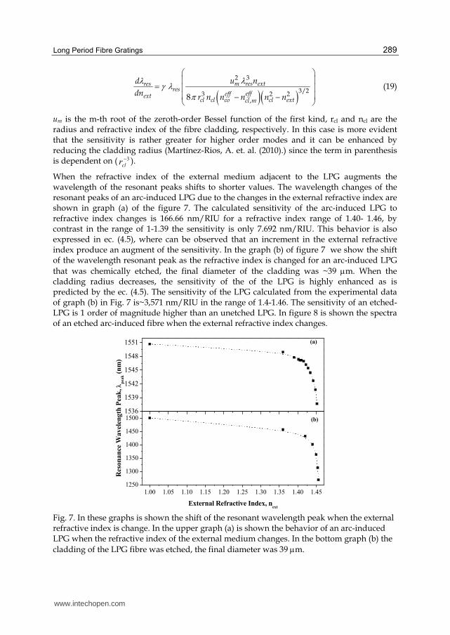
When the refractive index of the external medium adjacent to the LPG augments the wavelength of the resonant peaks shifts to shorter values. The wavelength changes of the resonant peaks of an arc-induced LPG due to the changes in the external refractive index are shown in graph (a) of the figure 7. The calculated sensitivity of the arc-induced LPG to refractive index changes is 166.66 nm/RIU for a refractive index range of 1.40- 1.46, by contrast in the range of 1-1.39 the sensitivity is only 7.692 nm/RIU. This behavior is also expressed in ec. (4.5), where can be observed that an increment in the external refractive index produce an augment of the sensitivity. In the graph (b) of figure 7 we show the shift of the wavelength resonant peak as the refractive index is changed for an arc-induced LPG
that was chemically etched, the final diameter of the cladding was ~39 m. When the cladding radius decreases, the sensitivity of the of the LPG is highly enhanced as is predicted by the ec. (4.5). The sensitivity of the LPG calculated from the experimental data of graph (b) in Fig. 7 is~3,571 nm/RIU in the range of 1.4-1.46. The sensitivity of an etched-LPG is 1 order of magnitude higher than an unetched LPG. In figure 8 is shown the spectra of an etched arc-induced fibre when the external refractive index changes.
1.00 1.05 1.10 1.15 1.20 1.25 1.30 1.35 1.40 1.451250
1300
1350
1400
1450
15001536
1539
1542
1545
1548
1551
(b)
Res
on
an
ce W
av
elen
gth
Pea
k, p
eak (
nm
)
External Refractive Index, next
(a)
Fig. 7. In these graphs is shown the shift of the resonant wavelength peak when the external refractive index is change. In the upper graph (a) is shown the behavior of an arc-induced LPG when the refractive index of the external medium changes. In the bottom graph (b) the
cladding of the LPG fibre was etched, the final diameter was 39 m.
www.intechopen.com
Fiber Optic Sensors
290
1250 1300 1350 1400 1450 1500 1550-25
-20
-15
-10
-5
0
next
=1.454
next
=1.44
next
=1.36
next
=1
Tra
nsm
issi
on
(d
B)
Wavelength (nm)
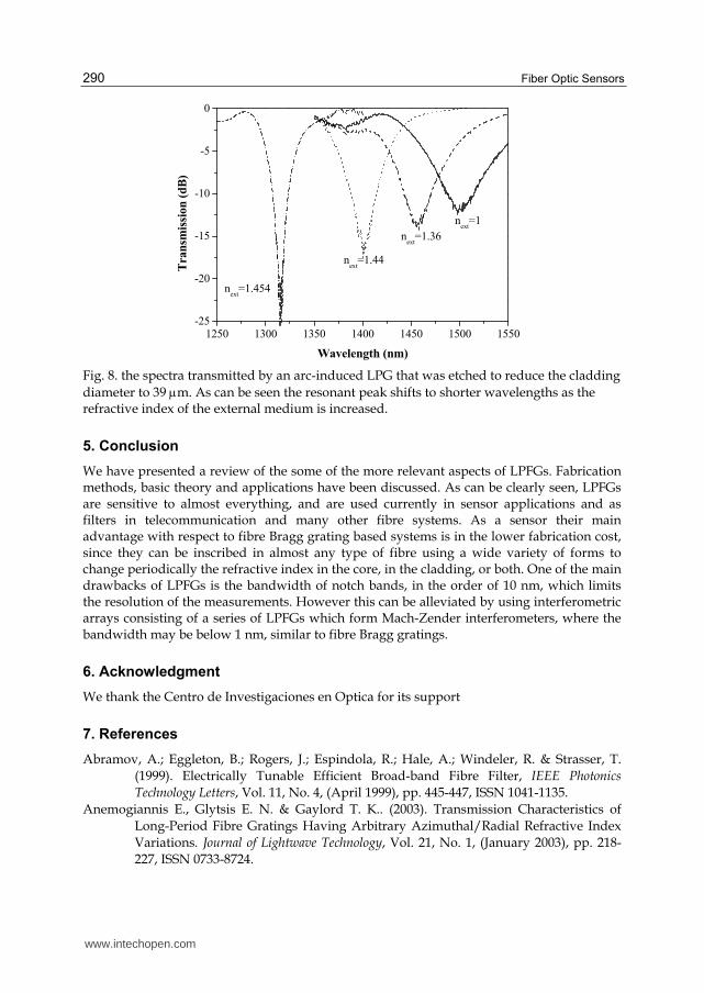
Fig. 8. the spectra transmitted by an arc-induced LPG that was etched to reduce the cladding
diameter to 39 m. As can be seen the resonant peak shifts to shorter wavelengths as the refractive index of the external medium is increased.
5. Conclusion
We have presented a review of the some of the more relevant aspects of LPFGs. Fabrication methods, basic theory and applications have been discussed. As can be clearly seen, LPFGs are sensitive to almost everything, and are used currently in sensor applications and as filters in telecommunication and many other fibre systems. As a sensor their main advantage with respect to fibre Bragg grating based systems is in the lower fabrication cost, since they can be inscribed in almost any type of fibre using a wide variety of forms to change periodically the refractive index in the core, in the cladding, or both. One of the main drawbacks of LPFGs is the bandwidth of notch bands, in the order of 10 nm, which limits the resolution of the measurements. However this can be alleviated by using interferometric arrays consisting of a series of LPFGs which form Mach-Zender interferometers, where the bandwidth may be below 1 nm, similar to fibre Bragg gratings.
6. Acknowledgment
We thank the Centro de Investigaciones en Optica for its support
7. References
Abramov, A.; Eggleton, B.; Rogers, J.; Espindola, R.; Hale, A.; Windeler, R. & Strasser, T.
(1999). Electrically Tunable Efficient Broad-band Fibre Filter, IEEE Photonics
Technology Letters, Vol. 11, No. 4, (April 1999), pp. 445-447, ISSN 1041-1135.
Anemogiannis E., Glytsis E. N. & Gaylord T. K.. (2003). Transmission Characteristics of
Long-Period Fibre Gratings Having Arbitrary Azimuthal/Radial Refractive Index
Variations. Journal of Lightwave Technology, Vol. 21, No. 1, (January 2003), pp. 218-
227, ISSN 0733-8724.
www.intechopen.com
Long Period Fibre Gratings
291
Arai, T. & Kragic, D. (1999). Variability of Wind and Wind Power, In: Wind Power, S.M.
Muyeen, (Ed.), 289-321, Scyio, ISBN 978-953-7619-81-7, Vukovar, Croatia
Bilodeau F., Malo B., Albert J., Johnson D. C., Hill K. O., Hibino Y., Abe M. & Kawachi M.
(1993). Photosensitization of optical fibre and silica-on-silicon/silica waveguides.
Optics Letters, Vol. 18, No. 12, (June 1993), pp. 953-955 , ISSN 0146-9592.
Bjarklev. (1986). Microdeformation losses of single-mode fibres with step- index profiles.
Journal of Lightwave Technology, Vol. 4, No. 3, (March 1986), pp. 341-346, , ISSN 0733-
8724.
Brambilla, G.; Kee, H.; Pruneri, V. & Newson, T. (2002). Optical fibre sensors for earth
science: From the basic concepts to optimizing glass composition for high
temperature applications, Optics and Lasers in Engineering, vol. 37, No. 2–3,
(February-March 2002), pp. 215–232, ISSN 0143-8166.
Bures J. (2009). Guided Optics:Optical Fibers and All-Fiber Components. WYLEY-VCH
(Weinheim, Germany). ISBN 978-3-527-40796-5.
Chan F. Y. & Yasumoto K. (2007). Design of wavelength tunable long-period grating
couplers based on asymmetric nonlinear dual-core fibres. Optics Letters, Vol. 32,
No. 23, (December 2007), pp. 3376-3378, , ISSN 0146-9592.
Chiang K. S.; Liu Y.; Ng M. N.; Dong X. (2000). Analysis of etched long-period fibre grating
and its response to external refractive index. Electonics Letters, Vol. 36, No. 11, (May
2000), pp. 966-967, ISSN 0013-5194.
Chunn-Yenn L., Wang L. A., Gia-Wei C. (1997). Corrugated long-period fibre gratings as
strain, torsion, and bending sensors. Journal of Lightwave Technology. Vol. 19, No. 8,
(August 2001), pp. 1159-1168, ISSN 0733-8724.
Davis, D.; Gaylord, T.; Glytis, E. & Mettler, S. (1998). CO2 laser-induced long-period fibre
gratings: spectral characteristics, cladding modes and polarization independence,
Electronics Letters, Vol. 34, No. 14, (July 1998), pp. 1414-1417, ISSN 00-13-5194.
Daxhelet, X. & Kulishov, M. (2003). Theory and practice of long-period gratings: when a loss
become a gain. Optics Letters, Vol. 28, No. 9,(May 2003), pp. 686-688, ISSN 0146-
9592.
DeLisa M. P., Zhang Z., Shiloach M., Pilevar S., Davis C. C., Sirkis J. S. & Bentley W. E. (2000).
Evanescent Wave Long-Period Fibre Bragg Grating as an Immobilized Antibody
Biosensor. Analytical Chemistry, Vol. 72, No. 13, (June 2000), pp. 2895–2900, ISSN
0003-2700.
Dianov E. M., Stardubov D. S., Vasiliev S. A., Frolov A. A., & Medvedkov O. I. (1997).
Refractive-index gratings written by near-ultraviolet radiation. Optics Letters Vol.
22, No. 4 , (February 1997), pp. 221-223, ISSN 0146-9592.
Eickhoff, W. (1981), Temperature sensing by mode-mode interference in birefringent optical
fibres, Optics Letters, Vol. 6, No. 4, (April 1981), pp. 204-206, ISSN 0146-9592.
Erdogan T. (1997). Cladding-mode resonances in short- and long-period fibre grating filters.
Journal of the Optical Society of America A, Vol. 14, No.8, (August 1997), pp. 1760-
2201, ISSN 0740-3232.
Fujimaki M., Ohki Y., Brebner J. L. & Roorda S. (2000). Fabrication of long-period optical
fibre gratings by use of ion implantation. Optics Letters. Vol. 25, No. 2, (January
2000), pp. 88-89, ISSN 0146-9592.
www.intechopen.com
Fiber Optic Sensors
292
Gu Z., Xu Y. & Gao K. (2006).Optical fibre long-period grating with solgel coating for gas
sensor. Optics Letters, Vol. 31, No. 16, (August 2006), pp. 2405-2407, ISSN 0146-9592.
Hill K. O., Malo B., Vineberg K. A., Bilodeau F., Johnson D. C.& Skinner I. (1990). Efficient
mode conversion in telecommunication fibre using externally written gratings.
Electronics Letters, Vol. 26, No 16, (August 1990), pp. 1270-1272, ISSN 0013-5194.
Hocker, G. (1979). Fibre-optic sensing of pressure and temperature, Applied Optics, Vol. 18,
No.9, (May 1979), pp. 1445-1448, ISSN 003-6935.
Hwang I. K., Yun S. H. & Kim B. Y.. (1999). Long-period fibre gratings based on periodic
microbends. Optics Letters, Vol. 24, No. 18, (September 1999), pp. 1263-1265, ISSN
0146-9592.
J. Lopez-Higuera, J. Ed., (2002). Handbook of Optical Fibre Sensing Technology, ISBN 978-0-471-
82053-6 Wiley, New York, USA
Jeong Y., Yang B., Lee B., Seo H. S., Choi S., Oh K. (2000). Electrically controllable long-
period liquid crystal fibre gratings. Photonics Technology Letters, Vol. 12, No. 519-
521, (May 2000), pp. 519 – 521, ISSN 1041-1135.
Kersey, A.; Davis, M.; Patrick, H.; LeBlanc, M.; Koo, K.; Askins, C.; Putnam, M. & Friebele, E.
(1997). Fibre Grating Sensors, Jorunal of Lightwave Technology, Vol. 15, No. 8, pp.
1442-1462, ISSN 0733-8724.
Kosinski, S., & Vengsarkar, A. (1998). Splicer-based long-period fiber gratings, Optical Fibre
Communication Conference, Vol. 2 of 1998 OSA Technical Digest Series (Optical
Society of America, 1998), ISBN 1557525293, paper ThG3..
Lemaire P. J., Atkins R. M., Mizrahi V. & Reed W. A. (1993). High pressure H2 loading as a
technique for achieving ultrahigh UV photosensitivity and thermal sensitivity in
GeO2 doped optical fibres, Electronics Letters, Vol. 29, No. 13, (June 1993), pp. 1191-
1193, ISSN 0013-5194.
Li, B.; Xu, Y. & Choi, J. (1996). Applying Machine Learning Techniques, Proceedings of ASME
2010 4th International Conference on Energy Sustainability, pp. 14-17, ISBN 842-6508-
23-3, Phoenix, Arizona, USA, May 17-22, 2010
Lima, P.; Bonarini, A. & Mataric, M. (2004). Application of Machine Learning, InTech, ISBN
978-953-7619-34-3, Vienna, Austria
Liu, Y.; Wang, L.; Zhang, M.; Tu, D.; Mao, X. & Lia, L (2007). Long-Period Grating Relative
Humidity Sensor with Hydrogel Coating, IEEE Photonics Technology Letters, Vol. 19,
No. 12,(June 2007), pp.880-882, ISSN 1041-1135.
Martínez-Rios, A.; Monzón-Hernández, D., & Torres-Gomez, I, (2010). Highly sensitive
cladding-etched arc-induced long-period fibre gratings for refractive index
sensing, Optics Communications, Vol. 283, No. 6, (March 2010), pp. 958-962, ISSN
0030-4018.
Miyagi, M. & Nishida, S., (1979). An approximate formula for describing dispersion
properties of optical dielectric slab and fibre waveguides, Journal of the Optical
Society of America Vol 69, No.2, (February 1997), pp. 291-293, ISSN 0030-3941.
Mohamed W. & Gu X. (2009). Long-period grating and its application in laser beam shaping
in the 1.0 m wavelength region, Applied Optics. Vol. 48, No. 12, (April 2009), pp.
2249-2254, ISSN 003-6935.
www.intechopen.com
Long Period Fibre Gratings
293
Ng M. N. & Chiang K. S. (2002). Thermal effects on the transmission spectra of long-period
fibre gratings. Optics Communications, Vol. 208, No. 4-6, (July 2002), pp. 321-327,
ISSN 0030-4018.
Othonos, A & Kalli, K. (1999). Fibre Bragg Gratings: Fundamentals and Applications in
Telecommunications and sensing, Artech House, ISBN 0-89006-344-3, Norwood, MA,
USA
Rao Y.J., Zhu T., Ran Z. L., Wang Y. P., Jiang J. & Hu A. Z. (2004). Novel long-period fibre
gratings written by high-frequency CO2 laser pulses and applications in optical
fibre communication. Optics Communications, Vol. 229, No. 1-6, (January 2004), pp.
209–221, ISSN 0030-4018.
Savin S., Digonnet M. J. F., Kino G. S & H. J. (2000). Tunable mechanically induced long-
period fibre gratings. Optics Letters, Vol. 25, No. 10, (May 2000), pp. 710 – 712, ISSN
0146-9592.
Shu Y., Lu C., Lacquet B. M., Swart P. L. & Spammer S. J. (2002). Wavelength-tunable
add/drop multiplexer for dense wavelength division multiplexing using long-
period gratings and fibre stretchers. Optics Communications, Vol. 208, No. 4-6,
(July 2002), pp. 337-344, ISSN 0030-4018.
Shu, X.; Allsop, T.; Zhang, L. & Bennion, (2001). High-Temperature Sensitivity of Long-
Period Gratings in B–Ge Codoped Fibre, IEEE Photonics Technology Letters, Vol. 13,
No. 8, (August 2001), pp. 818-820, ISSN 1041-1135.
Shu, X.; Zhang, L. & Bennion, I. (2002). Sensitivity Characteristics of Long-Period Fibre
Grating, Journal of Ligthwave Technology, Vol. 20, No.2, pp.255-266, ISSN 0733-8724.
Siegwart, R. (2001). Indirect Manipulation of a Sphere on a Flat Disk Using Force
Information. International Journal of Advanced Robotic Systems, Vol.6, No.4,
(December 2009), pp. 12-16, ISSN 1729-8806
Su C. D. & Wang L. A. (1999). Effect of Adding a Long Period Grating In a Double-Pass
Backward Er-Doped Superfluorescent Fibre Source. Journal of Lightwave Technology.
Vol. 17, No. 10, (October 1999), pp. 1896-1903, ISSN 0733-8724.
Van der Linden, S. (June 2010). Integrating Wind Turbine Generators (WTG’s) with
Energy Storage, In: Wind Power, 17.06.2010.
Vaziri M. & Chin-Lin C.. (1997). An etched two-mode fibre modal coupling element. Journal
of Lightwave Technology. Vol. 15, No. 3, (March 1997), pp. 474-481, ISSN 0733-8724.
Vengsarkar A.N., Lemaire P. J., Judkins J. B., No. Bhatia B., Erdogan T & Sipe J. E. (1996).
Long-period fibre gratings as band-rejection filters, Journal of Lightwave Technology,
Vol. 14, No. 1 , (January 1996), pp. 58-65, ISSN 0733-8724.
Vengsarkar, A. & Bhatia, B. (1996). Optical Fibre Long-Period Fibre Sensors, Optics Letters,
Vol. 21, No. 9, (May 1996), pp. 692-694, ISSN 0146-9592.
Vengsarkar, A.; Lemaire, P.; Judskin J.; Bhatia, B.; Erdogan, T. & Sipe, J. (1996). Long-Period
Fibre Gratings as Band-Rejection Filters, Journal of Lightwave Technology, Vol. 14, No.
1, (January 1996) pp. 58-64, ISSN 0733-8724.
Villatoro, J.; Monzón-Hernández, D. & Mejía, E. (200). Fabrication and modeling of uniform-
waist single-mode tapered optical fibre sensors, Applied Optics, Vol. 42, No. 13,
(May 2003), pp. 2278-2283, ISSN 0003-6935.
www.intechopen.com
Fiber Optic Sensors
294
Williams D. L., Ainslie B. J., Armitage J. R., Kashyap R., Campbell R. (1993). Enhanced UV
photosensitivity in boron codoped germanosilicate fibres. Electronics Letters, Vol.
29, No. 1, (January 1993), pp. 45-47, ISSN 0013-5194.
Zhang L., Liu Y., Everall L., Williams J. A. R. & Bennion I. (1999). Design and realization of
long period grating devices in conventional and high birefringence fibre and their
novel applications as fibre-optic load sensor. IEEE Journal of Selected Topics in
Quantum Electronics, Vol. 5, No. 5, (September/October 1999), pp. 1373-1378, ISSN
1077-260X.
www.intechopen.com
Fiber Optic SensorsEdited by Dr Moh. Yasin
ISBN 978-953-307-922-6Hard cover, 518 pagesPublisher InTechPublished online 22, February, 2012Published in print edition February, 2012
InTech EuropeUniversity Campus STeP Ri Slavka Krautzeka 83/A 51000 Rijeka, Croatia Phone: +385 (51) 770 447 Fax: +385 (51) 686 166www.intechopen.com
InTech ChinaUnit 405, Office Block, Hotel Equatorial Shanghai No.65, Yan An Road (West), Shanghai, 200040, China
Phone: +86-21-62489820 Fax: +86-21-62489821
This book presents a comprehensive account of recent advances and researches in fiber optic sensortechnology. It consists of 21 chapters encompassing the recent progress in the subject, basic principles ofvarious sensor types, their applications in structural health monitoring and the measurement of variousphysical, chemical and biological parameters. It also highlights the development of fiber optic sensors, theirapplications by providing various new methods for sensing and systems, and describing recent developmentsin fiber Bragg grating, tapered optical fiber, polymer optical fiber, long period fiber grating, reflectometry andinterefometry based sensors. Edited by three scientists with a wide knowledge of the field and the community,the book brings together leading academics and practitioners in a comprehensive and incisive treatment of thesubject. This is an essential reference for researchers working and teaching in optical fiber sensor technology,and for industrial users who need to be aware of current developments and new areas in optical fiber sensordevices.
How to referenceIn order to correctly reference this scholarly work, feel free to copy and paste the following:
Alejandro Martinez-Rios, David Monzon-Hernandez, Ismael Torres-Gomez and Guillermo Salceda-Delgado(2012). Long Period Fibre Gratings, Fiber Optic Sensors, Dr Moh. Yasin (Ed.), ISBN: 978-953-307-922-6,InTech, Available from: http://www.intechopen.com/books/fiber-optic-sensors/long-period-fibre-gratings